
Owner's Manual
ICRnFTSMnN,I
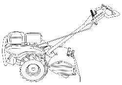
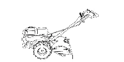
REAR TINE TILLER WITH
DUAL ROTATING TINES
7.0 HP
19 Inch Tine Width
Model No.
917.293493
This product has a low emission engine which operates
[_ differently from previously built engines. Before you start the
engine, read and understand this Owner's Manual.
Important:
Read and follow all Safety
Rules and Instructions before
operating this equipment.
Sears, Roebuck and Co., Hoffman Estates, IL 60179 U.S.A.
Visit our Craftsman website:www.sears.com/craftsman
Warranty ................................................ 2
Safety Rules .......................................... 2
Product Specifications ......................... 4
Assembly ............................................... 5
Operation ............................................... 8
Maintenance Schedule ........................ 14
Maintenance ....................................... 14
Service and Adjustments ..................... 16
Storage ................................................ 20
Troubleshooting ................................... 21
Illustrated Parts List ............................. 44
Sears Service ........................ Back Cover
LIMITED TWO YEAR WARRANTY ON CRAFTSMAN TILLER
For two (2) years from date of purchase, when this Craftsman Tiller is maintained,
lubricated, and tuned up according to the operating and maintenance instructions in the
owner's manual, Sears will repair free of charge any defect in material or workmanship.
This Warranty does not cover:
• Expendable items which become worn during normal use, such as tines, spark plugs,
air cleaners and belts.
• Repairs necessary because of operator abuse or negligence, including bent crank-
shafts and the failure to maintain the equipment according to the instructions con-
tained in the owner's manual.
• If this Craftsman Tiller is used for commercial or rental purposes, this Warranty applies
for only thirty (30) days from the date of purchase.
Warranty service is available by returning the craftsman power mower to the nearest
sears service center/department in the united states. This warranty applies only while
this product is in use in the united states.
This Warranty gives you specific legal rights, and you may also have other rights which
vary from state to state.
SEARS, ROEBUCK AND CO., D/817WA, HOFFMAN ESTATES, IL 60179 U.S.A.
IMPORTANT: This cutting machine is capable of amputating hands and feet and throw-
ing objects. Failure to observe the following safety instructions could result in serious
injury or death.
TRAINING
• Read the Owner's Manual carefully. Be
thoroughly familiar with the controls and
the proper use of the equipment. Know
how to stop the unit and disengage the
controls quickly.
• Never allow children to operate the
equipment. Never allow adults to op-
erate the equipment without proper
instruction.
• Keep the area of operation clear of all
persons, particularly small children, and
pets.
PREPARATION
• Thoroughly inspect the area where the
equipment is to be used and remove all
foreign objects.
• Disengage all clutches and shift into
neutral before starting the engine (mo-
tor).
• Do not operate the equipment without
wearing adequate outer garments. Wear
footwear that will improve footing on
slippery surfaces.
• Handle fuel with care; it is highly flam-
mable.
• Use an approved fuel container.
• Never add fuel to a running engine or
hot engine.
• Fill fuel tank outdoors with extreme care.
Never fill fuel tank indoors.
• Replace gasoline cap securely and
clean up spilled fuel before restarting.
2
• Use extension cords and receptacles
as specified by the manufacturer for all
units with electric drive motors or elec-
tric starting motors.
• Never attempt to make any adjustments
while the engine (motor) is running (ex-
cept where specifically recommended
by manufacturer).
OPERATION
• Do not put hands or feet near or under
rotating parts.
• Exercise extreme caution when operat-
ing on or crossing gravel drives, walks,
or roads. Stay alert for hidden hazards
or traffic. Do not carry passengers.
• After striking a foreign object, stop the
engine (motor), remove the wire from
the spark plug, thoroughly inspect the
tiller for any damage, and repair the
damage before restarting and operating
the tiller.
• Exercise caution to avoid slipping or fall-
ing.
• If the unit should start to vibrate ab-
normally, stop the engine (motor) and
check immediately for the cause. Vibra-
tion is generally a warning of trouble.
• Stop the engine (motor) when leaving
the operating position.
• Take all possible precautions when leav-
ing the machine unattended. Disengage
the tines, shift into neutral, and stop the
engine.
• Before cleaning, repairing, or inspecting,
shut off the engine and make certain all
moving parts have stopped. Disconnect
the spark plug wire, and keep the wire
away from the plug to prevent accidental
starting. Disconnect the cord on electric
motors.
• Do not run the engine indoors; exhaust
fumes are dangerous.
• Never operate the tiller without proper
guards, plates, or other safety protective
devices in place.
• Keep children and pets away.
• Do not overload the machine capacity
by attempting to till too deep at too fast
a rate.
• Never operate the machine at high
speeds on slippery surfaces. Look be-
hind and use care when backing.
• Never allow bystanders near the unit.
• Use only attachments and accessories
approved by the manufacturer of the
tiller.
• Never operate the tiller without good vis-
ibility or light.
• Be careful when tilling in hard ground.
The tines may catch in the ground and
propel the tiller forward. If this occurs,
let go of the handlebars and do not
restrain the machine.
MAINTENANCE AND STORAGE
• Keep machine, attachments, and ac-
cessories in safe working condition.
• Check shear pins, engine mounting
bolts, and other bolts at frequent inter-
vals for proper tightness to be sure the
equipment is in safe working condition.
• Never store the machine with fuel in the
fuel tank inside a building where ignition
sources are present, such as hot water
and space heaters, clothes dryers, and
the like. Allow the engine to cool before
storing in any enclosure.
• Always refer to the operator's guide
instructions for important details if the
tiller is to be stored for an extended
_period.
Look for this symbol to point out
important safety precautions. It means
CAUTION!!! BECOME ALERT!!! YOUR
SAFETY IS INVOLVED.
_CAUTION: Always disconnect spark
plug wire and place wire where it cannot
contact spark plug in order to prevent acci-
dental starting when setting up, transport-
ing, adjusting or making repairs.
_WARNING: Engine exhaust, some of its
constituents, and certain vehicle compo-
nents contain or emit chemicals known to
the State of California to cause cancer and
birth defects or other reproductive harm.
3
PRODUCT SPECIFICATIONS
Gasoline 4 Quarts
Capacity: Unleaded
Regular
Oil (API-SF-SJ): SAE 30 (Above 40°F)
(Capacity: 19 oz.) SAE5w-30/10W-30
(Below 40°F)
Spark Plug : Champion
(Gap: .030") RC12YC
CONGRATULATIONS on your purchase
of a Sears Tiller. It has been designed,
engineered and manufactured to give you
the best possible dependability and per-
formance.
Should you experience any problems you
cannot easily remedy, please contact a
Sears or other qualified Service Center.
We have competent, well-trained techni-
cians and the proper tools to service or
repair this unit.
Please read and retain this manual. The
instructions will enable you to assemble
and maintain your tiller properly. Always
observe the "SAFETY RULES".
Your new tiller has been assembled at the
factory with exception of those parts left
unassembled for shipping purposes. To
ensure safe and proper operation of your
tiller all parts and hardware you assemble
must be tightened securely. Use the cor-
rect tools as necessary to insure proper
tightness.
CUSTOMER RESPONSIBILITIES
• Read and observe the safety rules.
• Follow a regular schedule in main-
taining, caring for and using your tiller.
• Follow the instructions under the "Main-
tenance" and "Storage" sections of this
,j_Owner's Manual.
WARNING: This unit is equipped with
an internal combustion engine and should
not be used on or near any unimproved
forest-covered, brush-covered or grass
covered land unless the engine's exhaust
system is equipped with a spark arrester
meeting applicable local or state laws (if
any). If a spark arrester is used, it should
be maintained in effective working order
by the operator.
In the state of California the above is
required by law (Section 4442 of the
California Public Resources Code). Other
states may have similar laws. Federal
laws apply on federal lands. A spark ar-
rester for the muffler is available through
your nearest Sears service center (See
REPAIR PARTS section of this manual).
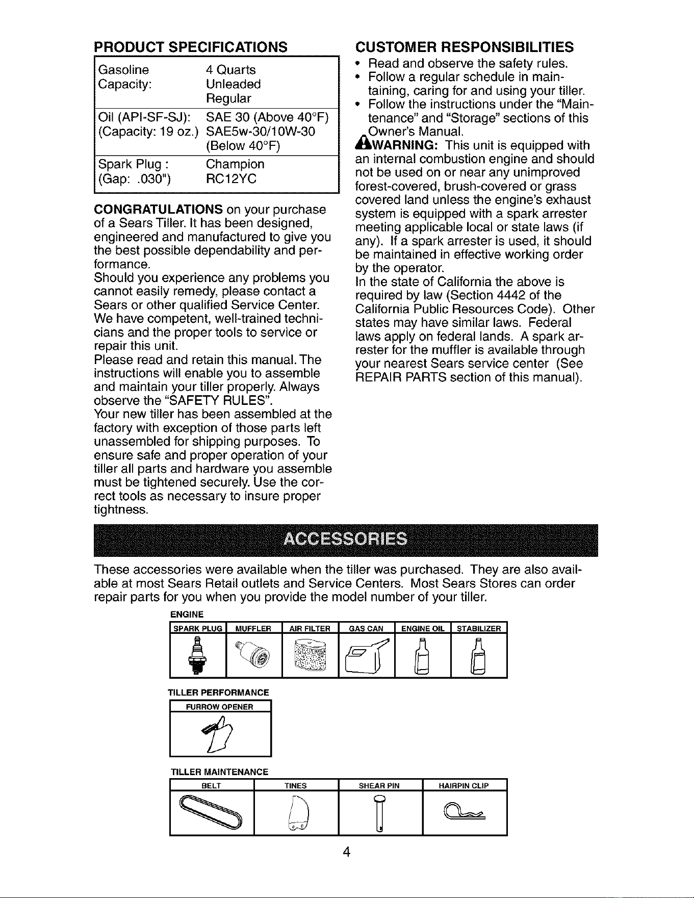
These accessories were available when the tiller was purchased. They are also avail-
able at most Sears Retail outlets and Service Centers. Most Sears Stores can order
repair parts for you when you provide the model number of your tiller.
ENGINE
SPARKPLUG_ MUFFLER AIR,FILTER [_GASCAN ENGINE_OIL STABILIZER
TILLER PERFORMANCE
TILLER MAINTENANCE
BELT TINES SHEAR PiN HAIRPIN CLIP
4
Your new tiller has been assembled at the factory with the exception of those parts left
unassembled for shipping purposes. To ensure safe and proper operation of your tiller
all parts and hardware you assemble must be tightened securely. Use the correct tools
as necessary to insure proper tightness.
TOOLS REQUIRED FOR
ASSEMBLY
A socket wrench set will make assembly
easier. Standard wrench sizes are listed.
(1) Utility knife
(1) Wire cutter
(1) Tire pressure gauge
(1) Screwdriver
(1) Pair of pliers
(1) 9/16" wrench
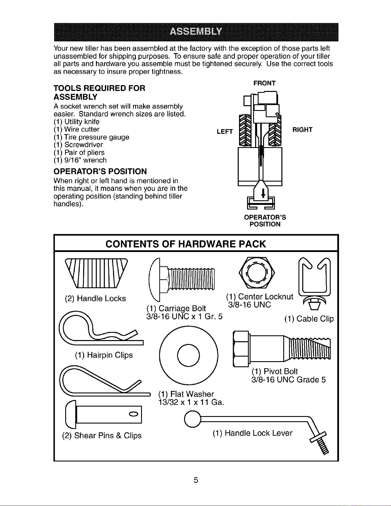
OPERATOR'S POSITION
When right or left hand is mentioned in
this manual, it means when you are in the
operating position (standing behind tiller
handles).
LEFT
FRONT
RIGHT
OPERATOR'S
POSITION
CONTENTS OF HARDWARE PACK
(2) Handle Locks
(1) Carriage Bolt
3/8-16 UNC x 1 Gr. 5
I
(1) Hairpin Clips ( ( ) )
I 13/32 x 1 xll Ca.
o 0
(2) Shear Pins & Clips
4#
(1) Center Locknut
3/8-16 UNC
(1) Cable Clip
(1) Pivot Bolt
3/8-16 UNC Grade 5
(1) Handle Lock Lever
5
UNPACKING CARTON
_CAUTION: Be careful of exposed sta-
ples when handling or disposing of carton-
ing material.
IMPORTANT: When unpacking and as-
sembling tiller, be careful not to stretch or
kink cables.
1. While holding handle assembly, cut
cable ties securing handle assembly to
top frame. Let handle assembly rest
on tiller.
2. Remove top frame of carton.
3. Slowly ease handle assembly up and
place on top of carton.
4. Cut down right hand front and right
hand rear corners of carton. Lay side
carton wall down.
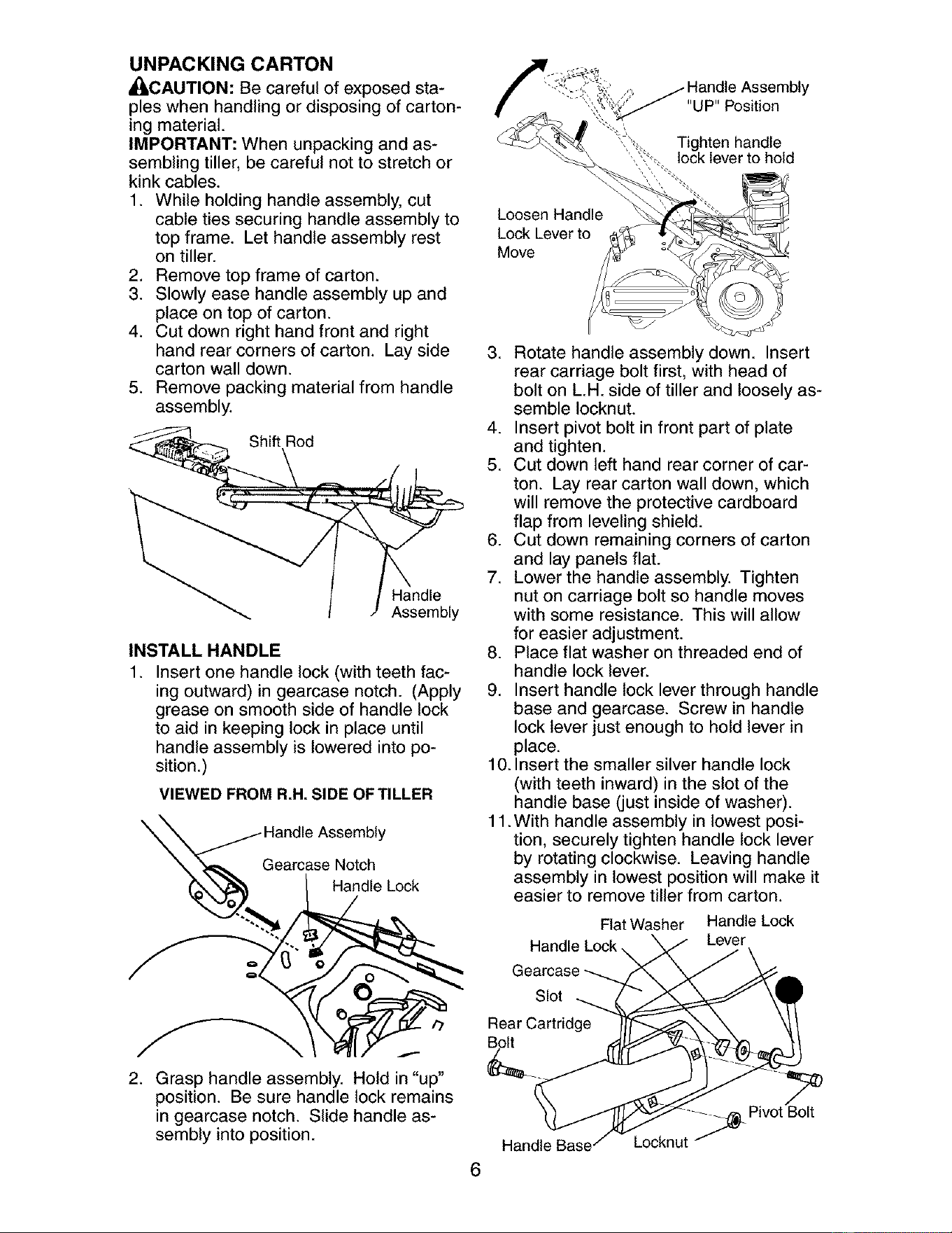
5. Remove packing material from handle
assembly.
Shift Rod
Handle
Assembly
INSTALL HANDLE
1. Insert one handle lock (with teeth fac-
ing outward) in gearcase notch. (Apply
grease on smooth side of handle lock
to aid in keeping lock in place until
handle assembly is lowered into po-
sition.)
VIEWED FROM R.H. SIDE OF TILLER
_. andle Assembly
Gearcase Notch
/ "a d'e oc"
2. Grasp handle assembly. Hold in "up"
position. Be sure handle lock remains
in gearcase notch. Slide handle as-
sembly into position.
"UP" Position
Tighten handle
lock lever to hold
Loosen Handle
Lock Lever to
Move
3. Rotate handle assembly down. Insert
rear carriage bolt first, with head of
bolt on L.H. side of tiller and loosely as-
semble Iocknut.
4. Insert pivot bolt in front part of plate
and tighten.
5. Cut down left hand rear corner of car-
ton. Lay rear carton wall down, which
will remove the protective cardboard
flap from leveling shield.
6. Cut down remaining corners of carton
and lay panels flat.
7. Lower the handle assembly. Tighten
nut on carriage bolt so handle moves
with some resistance. This will allow
for easier adjustment.
8. Place flat washer on threaded end of
handle lock lever.
9. Insert handle lock lever through handle
base and gearcase. Screw in handle
lock lever just enough to hold lever in
place.
10. Insert the smaller silver handle lock
(with teeth inward) in the slot of the
handle base (just inside of washer).
11 .With handle assembly in lowest posi-
tion, securely tighten handle lock lever
by rotating clockwise. Leaving handle
assembly in lowest position will make it
easier to remove tiller from carton.
Flat Washer Handle Lock
Lever
Slot
Rear Cartridge
Bolt
Handle Base
6
Locknut _
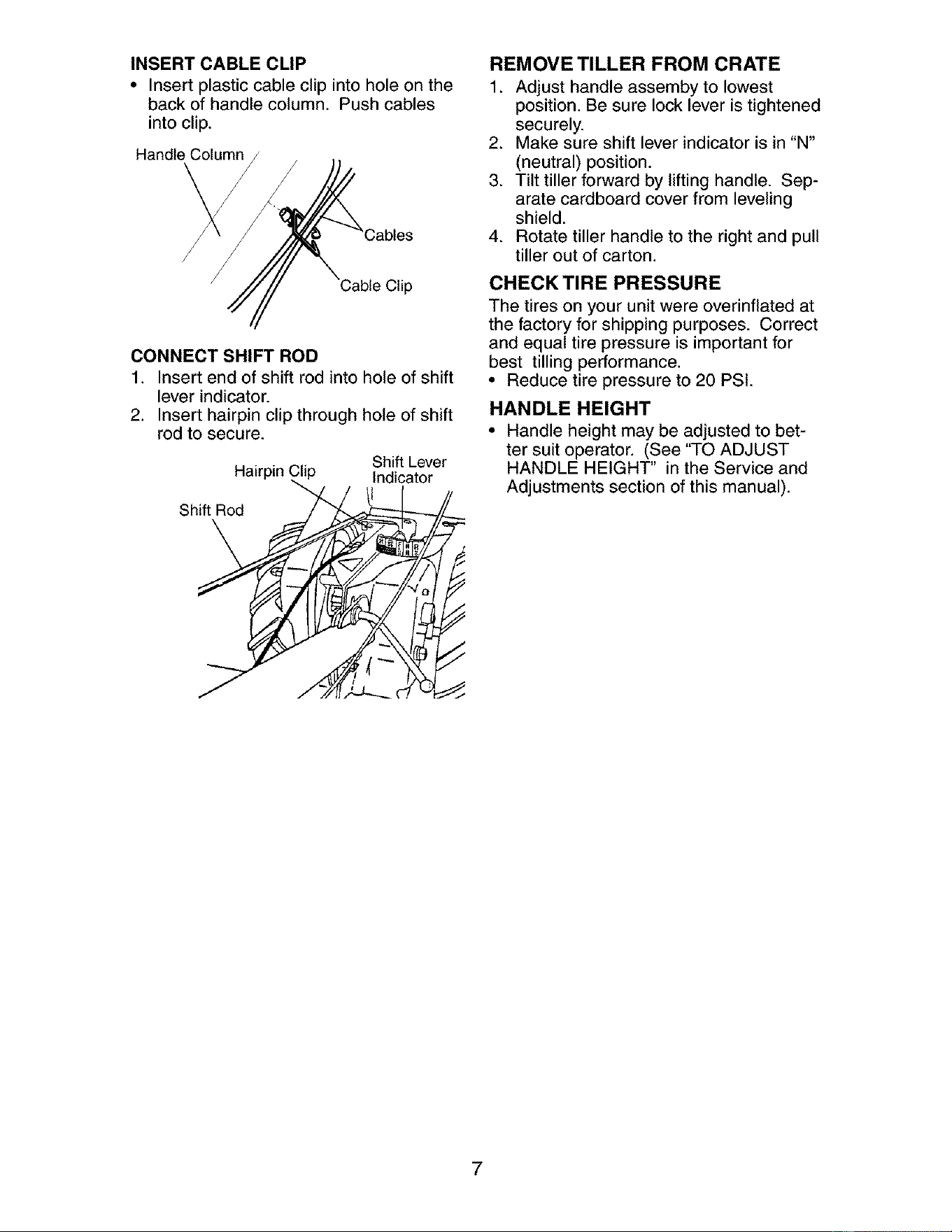
INSERT CABLE CLIP
• Insert plastic cable clip into hole on the
back of handle column. Push cables
into clip.
Handle Column
Cable Clip
CONNECT SHIFT ROD
1. Insert end of shift rod into hole of shift
lever indicator.
2. Insert hairpin clip through hole of shift
rod to secure.
Shift Lever
Hairpin ,_ Indicator
Shift Rod
REMOVE TILLER FROM CRATE
1. Adjust handle assemby to lowest
position. Be sure lock lever is tightened
securely.
2. Make sure shift lever indicator is in "N"
(neutral) position.
3. Tilt tiller forward by lifting handle. Sep-
arate cardboard cover from leveling
shield.
4. Rotate tiller handle to the right and pull
tiller out of carton.
CHECKTIRE PRESSURE
The tires on your unit were overinflated at
the factory for shipping purposes. Correct
and equal tire pressure is important for
best tilling performance.
• Reduce tire pressure to 20 PSI.
HANDLE HEIGHT
• Handle height may be adjusted to bet-
ter suit operator. (See "TO ADJUST
HANDLE HEIGHT" in the Service and
Adjustments section of this manual).
7
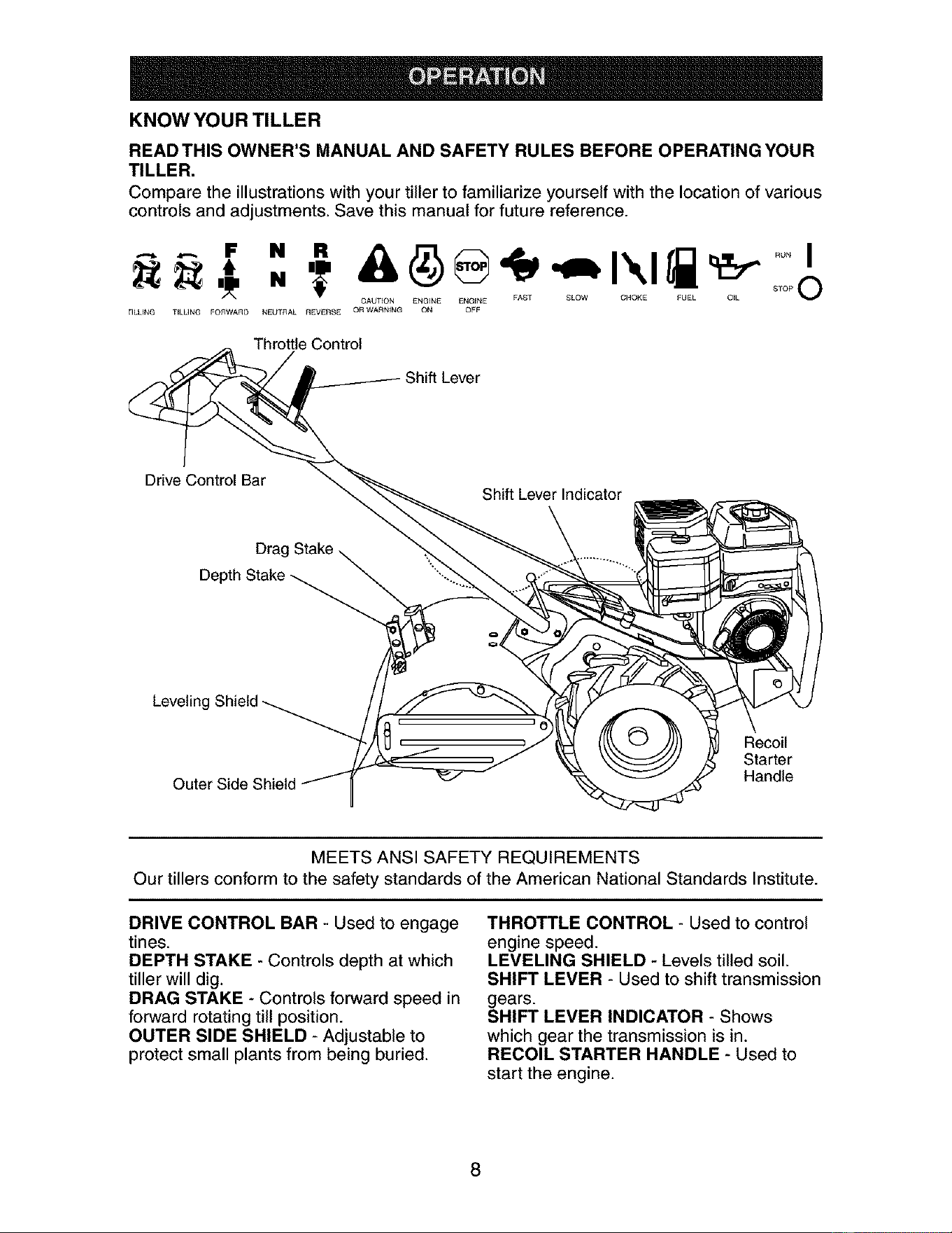
KNOW YOUR TILLER
READ THIS OWNER'S MANUAL AND SAFETY RULES BEFORE OPERATING YOUR
TILLER.
Compare the illustrations with your tiller to familiarize yourself with the location of various
controls and adjustments. Save this manual for future reference.
N O
CALtT_ON ENGINE ENGENE FAST SLOW CHOKE FUEL O_L
_ILUNG TELLING FOrWArD NEUTRAL REVERSE O_ WARNING ON OFF
Throttle Control
Drive Control Bar
Shift Lever Indicator
Drac
Depth Stake _
+
Leveling
Outer Side Shield
(_ Recoil
Starter
Handle
MEETS ANSI SAFETY REQUIREMENTS
Our tillers conform to the safety standards of the American National Standards Institute.
DRIVE CONTROL BAR - Used to engage
tines.
DEPTH STAKE - Controls depth at which
tiller will dig.
DRAG STAKE - Controls forward speed in
forward rotating till position.
OUTER SIDE SHIELD - Adjustable to
protect small plants from being buried.
THROTTLE CONTROL - Used to control
engine speed.
LEVELING SHIELD - Levels tilled soil.
SHIFT LEVER - Used to shift transmission
gears.
SHIFT LEVER INDICATOR - Shows
which gear the transmission is in.
RECOIL STARTER HANDLE - Used to
start the engine.
8
The operation of any tiller can result in foreign objects thrown into the eyes,
which can result in severe eye damage. Always wear safety glasses or eye
shields before starting your tiller and while tilling. We recommend standard
safety glasses or a wide vision safety mask worn over spectacles.
HOW TO USE YOUR TILLER
Know how to operate all controls before
adding fuel and oil or attempting to start
engine.
STOPPING
TINES AND DRIVE
1. Release drive control bar to stop move-
ment.
2. Move shift lever to "N" (neutral) po-
sition.
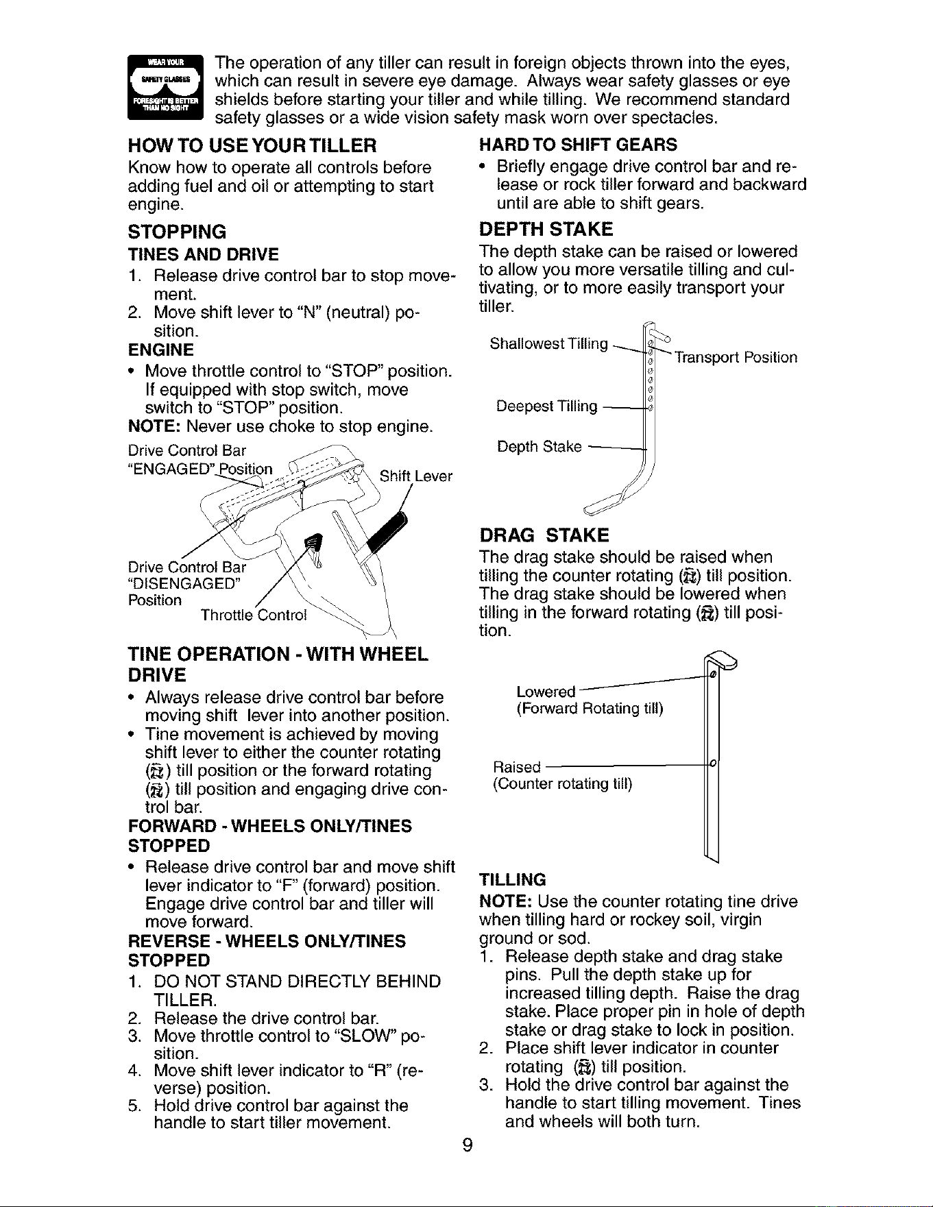
ENGINE
• Move throttle control to "STOP" position.
If equipped with stop switch, move
switch to "STOP" position.
NOTE: Never use choke to stop engine.
Drive Control Bar
"EN( Position
Shift Lever
HARD TO SHIFT GEARS
• Briefly engage drive control bar and re-
lease or rock tiller forward and backward
until are able to shift gears.
DEPTH STAKE
The depth stake can be raised or lowered
to allow you more versatile tilling and cul-
tivating, or to more easily transport your
tiller.
Shallowest Tilling
Deepest Tilling --
Depth Stake
_ Transport Position
Drive Control Bar
"DISENGAGED"
Position rol_
Throttle Cont
TINE OPERATION - WITH WHEEL
DRIVE
• Always release drive control bar before
moving shift lever into another position.
• Tine movement is achieved by moving
shift lever to either the counter rotating
(_;) till position or the forward rotating
(_) till position and engaging drive con-
trol bar.
FORWARD - WHEELS ONLY/TINES
STOPPED
• Release drive control bar and move shift
lever indicator to "F" (forward) position.
Engage drive control bar and tiller will
move forward.
REVERSE - WHEELS ONLY/TINES
STOPPED
1. DO NOT STAND DIRECTLY BEHIND
TILLER.
2. Release the drive control bar.
3. Move throttle control to "SLOW" po-
sition.
4. Move shift lever indicator to "R" (re-
verse) position.
5. Hold drive control bar against the
handle to start tiller movement.
DRAG STAKE
The drag stake should be raised when
tilling the counter rotating (_;) till position.
The drag stake should be lowered when
tilling in the forward rotating (_) till posi-
tion.
Lowered
(Forward Rotating till)
Raised
(Counter rotating till)
TILLING
NOTE: Use the counter rotating tine drive
when tilling hard or rockey soil, virgin
ground or sod.
1. Release depth stake and drag stake
pins. Pull the depth stake up for
increased tilling depth. Raise the drag
stake. Place proper pin in hole of depth
stake or drag stake to lock in position.
2. Place shift lever indicator in counter
rotating (_) till position.
3. Hold the drive control bar against the
handle to start tilling movement. Tines
and wheels will both turn.
9
4. Move throttle control to "FAST" position
for deep tilling.
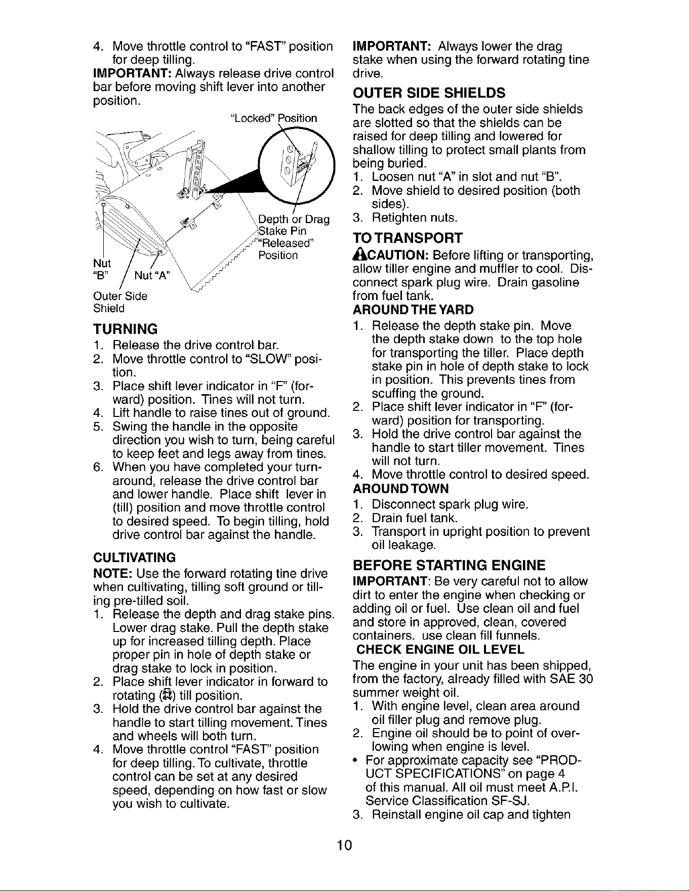
IMPORTANT: Always release drive control
bar before moving shift lever into another
position.
"Locked" Position
Nut
Outer Side
Shield
\Depth or Drag
/)Stake Pin
_S"Released"
Nut"A" _Position
TURNING
1. Release the drive control bar.
2. Move throttle control to "SLOW" posi-
tion.
3. Place shift lever indicator in "F" (for-
ward) position. Tines will not turn.
4. Lift handle to raise tines out of ground.
5. Swing the handle in the opposite
direction you wish to turn, being careful
to keep feet and legs away from tines.
6. When you have completed your turn-
around, release the drive control bar
and lower handle. Place shift lever in
(till) position and move throttle control
to desired speed. To begin tilling, hold
drive control bar against the handle.
CULTIVATING
NOTE: Use the forward rotating tine drive
when cultivating, tilling soft ground or till-
ing pre-tilled soil.
1. Release the depth and drag stake pins.
Lower drag stake. Pull the depth stake
up for increased tilling depth. Place
proper pin in hole of depth stake or
drag stake to lock in position.
2. Place shift lever indicator in forward to
rotating (_;) till position.
3. Hold the drive control bar against the
handle to start tilling movement. Tines
and wheels will both turn.
4. Move throttle control "FAST' position
for deep tilling. To cultivate, throttle
control can be set at any desired
speed, depending on how fast or slow
you wish to cultivate.
IMPORTANT: Always lower the drag
stake when using the forward rotating tine
drive.
OUTER SIDE SHIELDS
The back edges of the outer side shields
are slotted so that the shields can be
raised for deep tilling and lowered for
shallow tilling to protect small plants from
being buried.
1. Loosen nut "A" in slot and nut "B".
2. Move shield to desired position (both
sides).
3. Retighten nuts.
TO TRANSPORT
_CAUTION: Before lifting or transporting,
allow tiller engine and muffler to cool. Dis-
connect spark plug wire. Drain gasoline
from fuel tank.
AROUND THE YARD
1. Release the depth stake pin. Move
the depth stake down to the top hole
for transporting the tiller. Place depth
stake pin in hole of depth stake to lock
in position. This prevents tines from
scuffing the ground.
2. Place shift lever indicator in "F" (for-
ward) position for transporting.
3. Hold the drive control bar against the
handle to start tiller movement. Tines
will not turn.
4. Move throttle control to desired speed.
AROUND TOWN
1. Disconnect spark plug wire.
2. Drain fuel tank.
3. Transport in upright position to prevent
oil leakage.
BEFORE STARTING ENGINE
IMPORTANT: Be very careful not to allow
dirt to enter the engine when checking or
adding oil or fuel. Use clean oil and fuel
and store in approved, clean, covered
containers, use clean fill funnels.
CHECK ENGINE OIL LEVEL
The engine in your unit has been shipped,
from the factory, already filled with SAE 30
summer weight oil.
1. With engine level, clean area around
oil filler plug and remove plug.
2. Engine oil should be to point of over-
lowing when engine is level.
• For approximate capacity see "PROD-
UCT SPECIFICATIONS" on page 4
of this manual. All oil must meet A.P.I.
Service Classification SF-SJ.
3. Reinstall engine oil cap and tighten
10
• For cold weather operation you should
change oil for easier starting (See oil
viscosity chart in the Maintenance sec-
tion of this manual).
• To change engine oil, see the Mainte-
nance section in this manual.
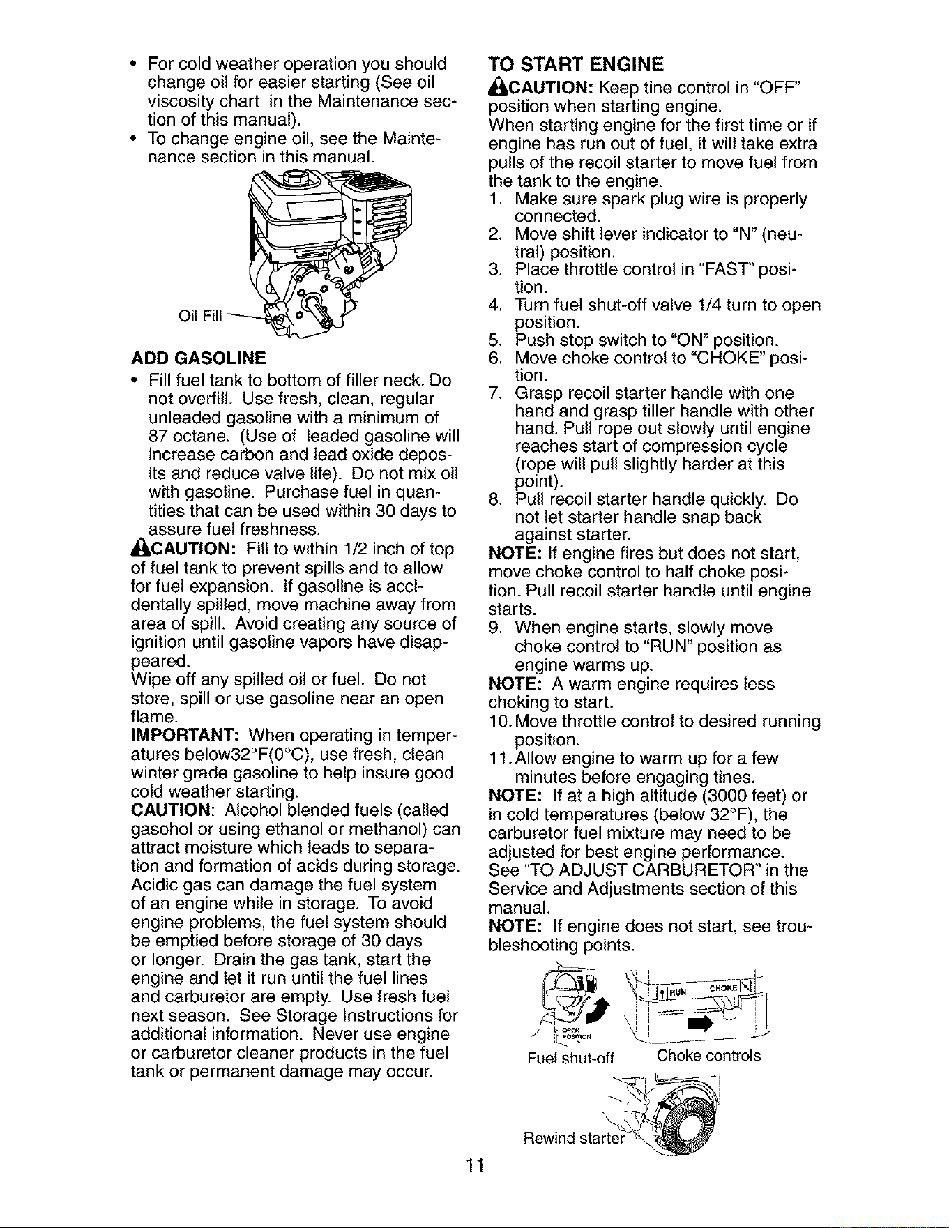
Oil
ADD GASOLINE
• Fill fuel tank to bottom of filler neck. Do
not overfill. Use fresh, clean, regular
unleaded gasoline with a minimum of
87 octane. (Use of leaded gasoline will
increase carbon and lead oxide depos-
its and reduce valve life). Do not mix oil
with gasoline. Purchase fuel in quan-
tities that can be used within 30 days to
assure fuel freshness.
_CAUTION: Fill to within 1/2 inch of top
of fuel tank to prevent spills and to allow
for fuel expansion. If gasoline is acci-
dentally spilled, move machine away from
area of spill. Avoid creating any source of
ignition until gasoline vapors have disap-
peared.
Wipe off any spilled oil or fuel. Do not
store, spill or use gasoline near an open
flame.
IMPORTANT: When operating in temper-
atures below32°F(0°C), use fresh, clean
winter grade gasoline to help insure good
cold weather starting.
CAUTION: Alcohol blended fuels (called
gasohol or using ethanol or methanol) can
attract moisture which leads to separa-
tion and formation of acids during storage.
Acidic gas can damage the fuel system
of an engine while in storage. To avoid
engine problems, the fuel system should
be emptied before storage of 30 days
or longer. Drain the gas tank, start the
engine and let it run until the fuel lines
and carburetor are empty. Use fresh fuel
next season. See Storage Instructions for
additional information. Never use engine
or carburetor cleaner products in the fuel
tank or permanent damage may occur.
11
TO START ENGINE
_CAUTION: Keep tine control in "OFF"
position when starting engine.
When starting engine for the first time or if
engine has run out of fuel, it will take extra
pulls of the recoil starter to move fuel from
the tank to the engine.
1. Make sure spark plug wire is properly
connected.
2. Move shift lever indicator to "N" (neu-
tral) position.
3. Place throttle control in "FAST" posi-
tion.
4. Turn fuel shut-off valve 1/4 turn to open
position.
5. Push stop switch to "ON" position.
6. Move choke control to "CHOKE" posi-
tion.
7. Grasp recoil starter handle with one
hand and grasp tiller handle with other
hand. Pull rope out slowly until engine
reaches start of compression cycle
(rope will pull slightly harder at this
point).
8. Pull recoil starter handle quickly. Do
not let starter handle snap back
against starter.
NOTE: If engine fires but does not start,
move choke control to half choke posi-
tion. Pull recoil starter handle until engine
starts.
9. When engine starts, slowly move
choke control to "RUN" position as
engine warms up.
NOTE: A warm engine requires less
choking to start.
10. Move throttle control to desired running
position.
11 .Allow engine to warm up for a few
minutes before engaging tines.
NOTE: If at a high altitude (3000 feet) or
in cold temperatures (below 32°F), the
carburetor fuel mixture may need to be
adjusted for best engine performance.
See "TO ADJUST CARBURETOR" in the
Service and Adjustments section of this
manual.
NOTE: If engine does not start, see trou-
bleshooting points.
Fuel shut-off Choke controls
,_1 i
Rewind star_'
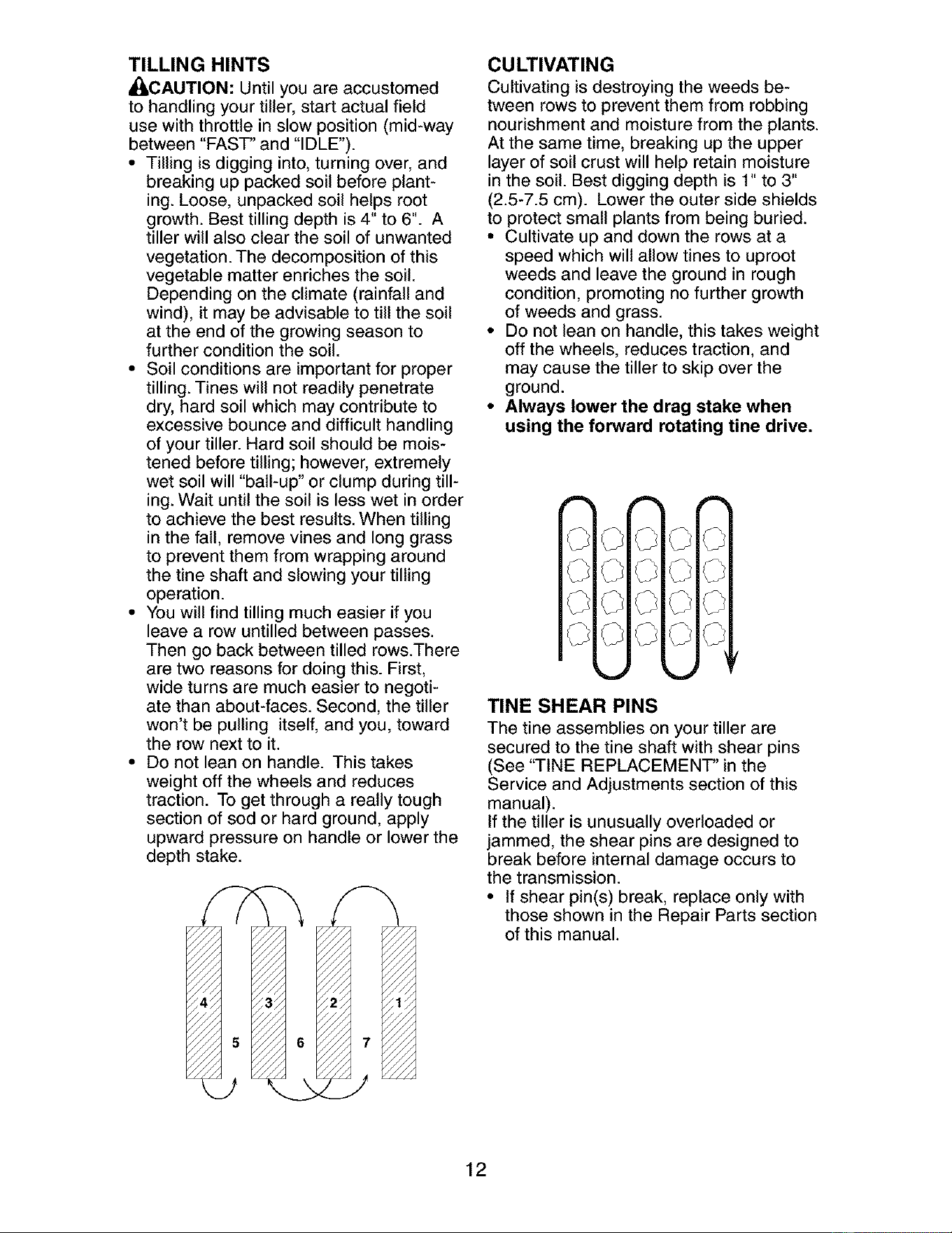
TILLING HINTS
_CAUTION: Until you are accustomed
to handling your tiller, start actual field
use with throttle in slow position (mid-way
between "FAST" and "IDLE").
• Tilling is digging into, turning over, and
breaking up packed soil before plant-
ing. Loose, unpacked soil helps root
growth. Best tilling depth is 4" to 6". A
tiller will also clear the soil of unwanted
vegetation. The decomposition of this
vegetable matter enriches the soil.
Depending on the climate (rainfall and
wind), it may be advisable to till the soil
at the end of the growing season to
further condition the soil.
• Soil conditions are important for proper
tilling. Tines will not readily penetrate
dry, hard soil which may contribute to
excessive bounce and difficult handling
of your tiller. Hard soil should be mois-
tened before tilling; however, extremely
wet soil will "ball-up" or clump during till-
ing. Wait until the soil is less wet in order
to achieve the best results. When tilling
in the fall, remove vines and long grass
to prevent them from wrapping around
the tine shaft and slowing your tilling
operation.
• You will find tilling much easier if you
leave a row untilled between passes.
Then go back between tilled rows.There
are two reasons for doing this. First,
wide turns are much easier to negoti-
ate than about-faces. Second, the tiller
won't be pulling itself, and you, toward
the row next to it.
• Do not lean on handle. This takes
weight off the wheels and reduces
traction. To get through a really tough
section of sod or hard ground, apply
upward pressure on handle or lower the
depth stake.
CULTIVATING
Cultivating is destroying the weeds be-
tween rows to prevent them from robbing
nourishment and moisture from the plants.
At the same time, breaking up the upper
layer of soil crust will help retain moisture
in the soil. Best digging depth is 1" to 3"
(2.5-7.5 cm). Lower the outer side shields
to protect small plants from being buried.
• Cultivate up and down the rows at a
speed which will allow tines to uproot
weeds and leave the ground in rough
condition, promoting no further growth
of weeds and grass.
* Do not lean on handle, this takes weight
off the wheels, reduces traction, and
may cause the tiller to skip over the
ground.
* Always lower the drag stake when
using the forward rotating tine drive.
TINE SHEAR PINS
The tine assemblies on your tiller are
secured to the tine shaft with shear pins
(See "TINE REPLACEMENT" in the
Service and Adjustments section of this
manual).
If the tiller is unusually overloaded or
jammed, the shear pins are designed to
break before internal damage occurs to
the transmission.
• If shear pin(s) break, replace only with
those shown in the Repair Parts section
of this manual.
12
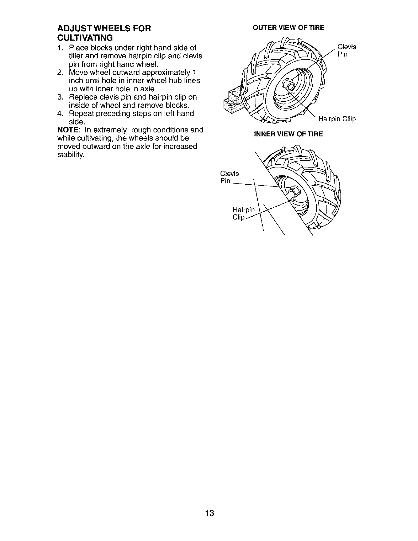
ADJUST WHEELS FOR
CULTIVATING
1. Place blocks under right hand side of
tiller and remove hairpin clip and clevis
pin from right hand wheel.
2. Move wheel outward approximately 1
inch until hole in inner wheel hub lines
up with inner hole in axle.
3. Replace clevis pin and hairpin clip on
inside of wheel and remove blocks.
4. Repeat preceding steps on left hand
side.
NOTE: In extremely rough conditions and
while cultivating, the wheels should be
moved outward on the axle for increased
stability.
OUTER VIEW OF TIRE
Hairpin Cllip
INNER VIEW OF TIRE
Clevis
Pin
Hairpin
13

MAINTENANCE
SCHEDULE
FILL IN DATES
AS YOU COMPLETE
REGULAR SERVICE / y yy SE V,OEO TES
Check Engine Oil Level I1_
Change Engine Oil 11_2
Oil Pivot Points I_
Inspect Spark Arrester / Muffler
Inspect Air Screen
Clean or Replace Air Cleaner Cartridge
Clean Engine Cylinder Fins
Replace Spark Plug
RH Gear Case Grease Fitting (loz,)
1 - Change more often when operatingunder a heavy loador in high ambient temperatures.
2 - Sel_dcemoreoften when operating in dirty or dusty conditions.
GENERAL RECOMMENDATIONS
The warranty on this tiller does not cover
items that have been subjected to op-
erator abuse or negligence. To receive full
value from the warranty, the operator must
maintain tiller as instructed in this manual.
Some adjustments will need to be made
periodically to properly maintain your tiller.
All adjustments in the Service and Adjust-
ments section of this manual should be
checked at least once each season.
• Once a year you should replace the
spark plug, clean or replace air filter,
and check tines and belts for wear. A
new spark plug and clean air filter as-
sure proper air-fuel mixture and help
your engine run better and last longer.
BEFORE EACH USE
1. Check engine oil level.
2. Check tine operation.
3. Check for loose fasteners.
LUBRICATION
Keep unit well lubricated (See "LUBRI-
CATION CHART").
LUBRICATION CHART
OThrottle Control
®RH Gear Case
®Engi_ Grease Fitting
®Depth Stake Pin
®Idler
Bracket ®Wheel Hub
Shield
Hinges
O SAE 30 OR 10W-30 Motor Oil
(3) Refer to Maintenance "ENGINE" section
(3) EP #1 Grease
14
_I:_CAUTION: Disconnect spark plug
wire before performing any maintenance
(except carburetor adjustment) to prevent
accidental starting of engine.
Prevent fires! Keep the engine free of
grass, leaves, spilled oil, or fuel. Remove
fuel from tank before tipping unit for main-
tenance. Clean muffler area of all grass,
dirt, and debris.
Do not touch hot muffler or cylinder fins as
contact may cause burns.
ENGINE
LUBRICATION
Use only high quality detergent oil rated
with API service classification SF-SJ. Se-
lect the oil's SAE viscosity grade accord-
ing to your expected temperature.
SAE VISCOSITY GRADES
F 80
c .3o .G _ G _o 3o
TEMPERATURE RANGE ANTICIPATED BEFORE NEXT OIL CHANGE
ol vi_ _l_atl5 #/drll
NOTE: Although multi-viscosity oils
(5W-30, 10W-30, etc.) improve starting
in cold weather, these multi-viscosity oils
will result in increased oil consumption
when used above 4O°F (4°C). Check your
engine oil level more frequently to avoid
possible engine damage from running low
on oil.
Change the oil after every 50 hours of
operation or at least once a year if the tiller
is not used for 50 hours in one year.
Check the crankcase oil level before
starting the engine and after each five (5)
hours of continuous use. Add SAE 30 mo-
tor oil or equivalent. Tighten oil filler plug
securely each time you check the oil level.
TO CHANGE ENGINE OIL
Determine temperature range expected
before oil change. All oil must meet API
service classification SF-SJ.
• Be sure tiller is on level surface.
• Oil will drain more freely when warm.
• Use a funnel to prevent oil spill on tiller,
and catch oil in a suitable container.
1. Remove drain plug.
For easier removal of plug use 7/16- 12
Pt. socket with extension.
2. Tip tiller forward to drain oil.
3. After oil has drained completely,
replace oil drain plug and tighten se-
curely.
4. Remove oil filler plug. Be careful not to
allow dirt to enter the engine.
15
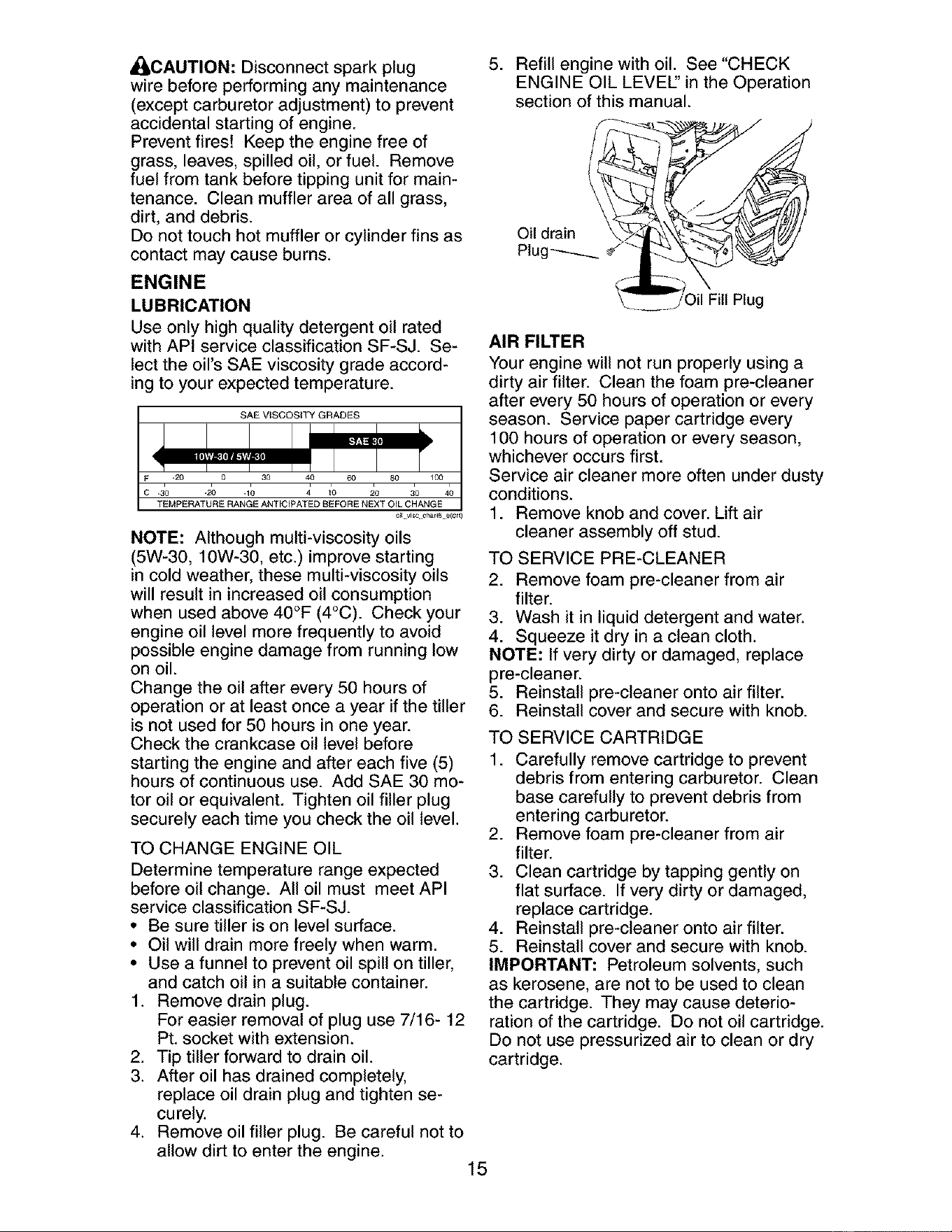
.
Refill engine with oil. See "CHECK
ENGINE OIL LEVEl" in the Operation
section of this manual.
\_ __ _iOil Fill Plug
t
AIR FILTER
Your engine will not run properly using a
dirty air filter. Clean the foam pre-cleaner
after every 50 hours of operation or every
season. Service paper cartridge every
1OOhours of operation or every season,
whichever occurs first.
Service air cleaner more often under dusty
conditions.
1. Remove knob and cover. Lift air
cleaner assembly off stud.
TO SERVICE PRE-CLEANER
2. Remove foam pre-cleaner from air
filter.
3. Wash it in liquid detergent and water.
4. Squeeze it dry in a clean cloth.
NOTE: If very dirty or damaged, replace
pre-cleaner.
5. Reinstall pre-cleaner onto air filter.
6. Reinstall cover and secure with knob.
TO SERVICE CARTRIDGE
1. Carefully remove cartridge to prevent
debris from entering carburetor. Clean
base carefully to prevent debris from
entering carburetor.
2. Remove foam pre-cleaner from air
filter.
3. Clean cartridge by tapping gently on
flat surface. If very dirty or damaged,
replace cartridge.
4. Reinstall pre-cleaner onto air filter.
5. Reinstall cover and secure with knob.
IMPORTANT: Petroleum solvents, such
as kerosene, are not to be used to clean
the cartridge. They may cause deterio-
ration of the cartridge. Do not oil cartridge.
Do not use pressurized air to clean or dry
cartridge.
__---_---- Cover Knob
Prlciilrni _ Cartridge
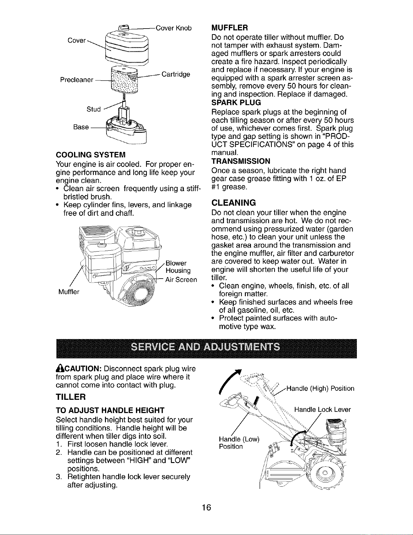
COOLING SYSTEM
Your engine is air cooled. For proper en-
gine performance and long life keep your
engine clean.
• Clean air screen frequently using a stiff-
bristled brush.
• Keep cylinder fins, levers, and linkage
free of dirt and chaff.
Muffler
•Blower
Housing
Air Screen
MUFFLER
Do not operate tiller without muffler. Do
not tamper with exhaust system. Dam-
aged mufflers or spark arresters could
create a fire hazard. Inspect periodically
and replace if necessary. If your engine is
equipped with a spark arrester screen as-
sembly, remove every 50 hours for clean-
ing and inspection. Replace if damaged.
SPARK PLUG
Replace spark plugs at the beginning of
each tilling season or after every 50 hours
of use, whichever comes first. Spark plug
type and gap setting is shown in "PROD-
UCT SPECIFICATIONS" on page 4 of this
manual.
TRANSMISSION
Once a season, lubricate the right hand
gear case grease fitting with 1 oz. of EP
#1 grease.
CLEANING
Do not clean your tiller when the engine
and transmission are hot. We do not rec-
ommend using pressurized water (garden
hose, etc.) to clean your unit unless the
gasket area around the transmission and
the engine muffler, air filter and carburetor
are covered to keep water out. Water in
engine will shorten the useful life of your
tiller.
• Clean engine, wheels, finish, etc. of all
foreign matter.
• Keep finished surfaces and wheels free
of all gasoline, oil, etc.
• Protect painted surfaces with auto-
motive type wax.
,_CAUTION: Disconnect spark plug wire
from spark plug and place wire where it
cannot come into contact with plug.
TILLER
TO ADJUST HANDLE HEIGHT
Select handle height best suited for your
tilling conditions. Handle height will be
different when tiller digs into soil.
1. First loosen handle lock lever.
2. Handle can be positioned at different
settings between "HIGH" and "LOW"
positions.
3. Retighten handle lock lever securely
after adjusting.
Handle (Low)
Position
.Handle (High) Position
",,'i,_. Handle Lock Lever
16
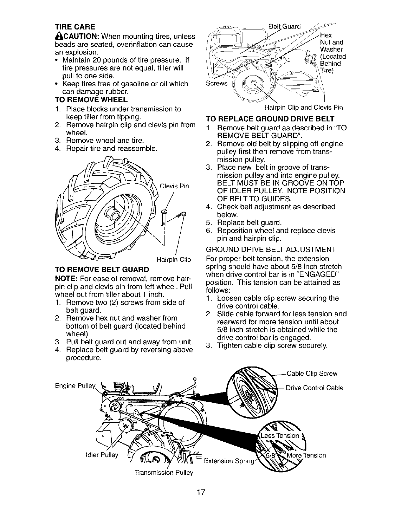
TIRE CARE
_CAUTION: When mounting tires, unless
beads are seated, overinflation can cause
an explosion.
• Maintain 20 pounds of tire pressure. If
tire pressures are not equal, tiller will
pull to one side.
• Keep tires free of gasoline or oil which
can damage rubber.
TO REMOVE WHEEL
1. Place blocks under transmission to
keep tiller from tipping.
2. Remove hairpin clip and clevis pin from
wheel.
3. Remove wheel and tire.
4. Repair tire and reassemble.
_ Clevis Pin
I
Hairpin Clip
TO REMOVE BELT GUARD
NOTE: For ease of removal, remove hair-
pin clip and clevis pin from left wheel. Pull
wheel out from tiller about 1 inch.
1. Remove two (2) screws from side of
belt guard.
2. Remove hex nut and washer from
bottom of belt guard (located behind
wheel).
3. Pull belt guard out and away from unit.
4. Replace belt guard by reversing above
procedure.
Engine Pulley,
Guard
• Hex
Nut and
Washer
(Located
Behind
Screws
Hairpin Clip and Clevis Pin
TO REPLACE GROUND DRIVE BELT
1. Remove belt guard as described in "TO
REMOVE BELT GUARD".
2. Remove old belt by slipping off engine
pulley first then remove from trans-
mission pulley.
3. Place new belt in groove of trans-
mission pulley and into engine pulley.
BELT MUST BE IN GROOVE ON TOP
OF IDLER PULLEY. NOTE POSITION
OF BELT TO GUIDES.
4. Check belt adjustment as described
below.
5. Replace belt guard.
6. Reposition wheel and replace clevis
pin and hairpin clip.
GROUND DRIVE BELT ADJUSTMENT
For proper belt tension, the extension
spring should have about 5/8 inch stretch
when drive control bar is in "ENGAGED"
position. This tension can be attained as
follows:
1. Loosen cable clip screw securing the
drive control cable.
2. Slide cable forward for less tension and
rearward for more tension until about
5/8 inch stretch is obtained while the
drive control bar is engaged.
3. Tighten cable clip screw securely.
Clip Screw
Cable
Idler Pulley
Extension Sprin_
Transmission Pulley
More Tension
17
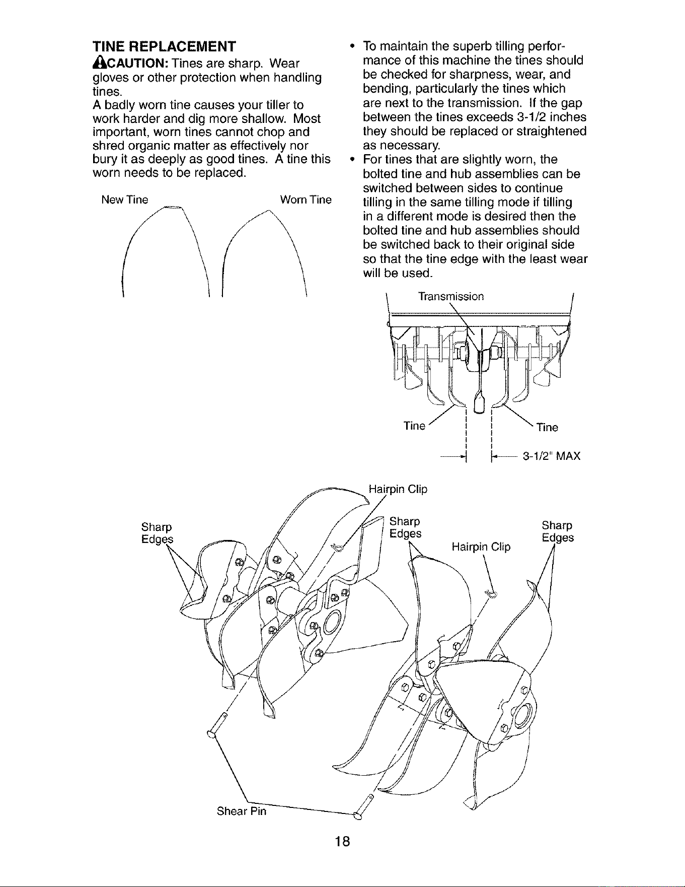
TINE REPLACEMENT •
_CAUTION: Tines are sharp. Wear
gloves or other protection when handling
tines.
A badly worn tine causes your tiller to
work harder and dig more shallow. Most
important, worn tines cannot chop and
shred organic matter as effectively nor
bury it as deeply as good tines. A tine this •
worn needs to be replaced.
New Tine
&
Worn Tine
To maintain the superb tilling perfor-
mance of this machine the tines should
be checked for sharpness, wear, and
bending, particularly the tines which
are next to the transmission. If the gap
between the tines exceeds 3-1/2 inches
they should be replaced or straightened
as necessary.
For tines that are slightly worn, the
bolted tine and hub assemblies can be
switched between sides to continue
tilling in the same tilling mode if tilling
in a different mode is desired then the
bolted tine and hub assemblies should
be switched back to their original side
so that the tine edge with the least wear
will be used.
I I
I I
I I
--_ _ 3-1/2" MAX
Sharp
P
Hairpin Clip
Sharp
18
ENGINE
Maintenance, repair, or replacement of
the emission control devices and systems,
which are being done at the customers ex-
pense, may be performed by any non-road
engine repair establishment or individual.
Warranty repairs must be performed by an
authorized engine manufacturer's service
outlet.
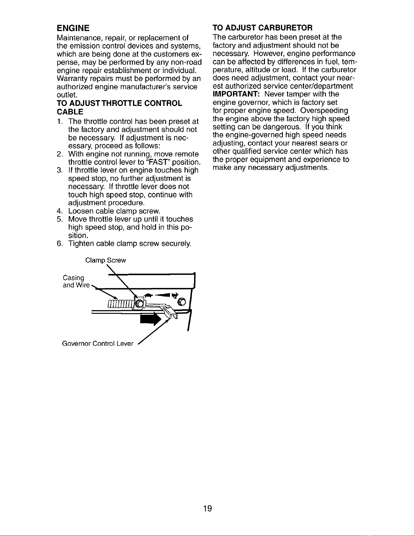
TO ADJUST THROTTLE CONTROL
CABLE
1. The throttle control has been preset at
the factory and adjustment should not
be necessary. If adjustment is nec-
essary, proceed as follows:
2. With engine not running, move remote
throttle control lever to "FAST" position.
3. If throttle lever on engine touches high
speed stop, no further adjustment is
necessary. If throttle lever does not
touch high speed stop, continue with
adjustment procedure.
4. Loosen cable clamp screw.
5. Move throttle lever up until it touches
high speed stop, and hold in this po-
sition.
6. Tighten cable clamp screw securely.
Clamp Screw
\
aCn_c_i_/gre _, "X_
Governor Control Lever
TO ADJUST CARBURETOR
The carburetor has been preset at the
factory and adjustment should not be
necessary. However, engine performance
can be affected by differences in fuel, tem-
perature, altitude or load. If the carburetor
does need adjustment, contact your near-
est authorized service center/department
IMPORTANT: Never tamper with the
engine governor, which is factory set
for proper engine speed. Overspeeding
the engine above the factory high speed
setting can be dangerous. If you think
the engine-governed high speed needs
adjusting, contact your nearest sears or
other qualified service center which has
the proper equipment and experience to
make any necessary adjustments.
19
Immediately prepare your tiller for storage
at the end of the season or if the unit will
not be used for 30 days or more.
A(_WARNING: Never store the tiller with
gasoline in the tank inside a building
where fumes may reach an open flame
or spark. Allow the engine to cool before
storing in any enclosure.
TILLER
1. Clean entire tiller (See "CLEANING" in
the Maintenance section of this man-
ual).
2. Inspect and replace belts, if necessary
(See belt replacement instructions in
the Service and Adjustments section of
this manual).
3. Lubricate as shown in the Maintenance
section of this manual.
4. Be sure that all nuts, bolts and screws
are securely fastened. Inspect moving
parts for damage, breakage and wear.
Replace if necessary.
5. Touch up all rusted or chipped paint
surfaces; sand lightly before painting.
ENGINE
FUEL SYSTEM
IMPORTANT: It is important to prevent
gum deposits from forming in essential
fuel system parts such as the carburetor,
fuel filter, fuel hose, or tank during storage.
Also, alcohol blended fuels (called gasohol
or using ethanol or methanol) can attract
moisture which leads to separation and
formation of acids during storage. Acidic
gas can damage the fuel system of an
engine while in storage.
1. Drain the fuel tank.
2. Start the engine and let it run until the
fuel lines and carburetor are empty.
• Never use engine or carburetor cleaner
products in the fuel tank or permanent
damage may occur.
• Use fresh fuel next season.
NOTE: Fuel stabilizer is an acceptable
alternative in minimizing the formation of
fuel gum deposits during storage. Add
stabilizer to gasoline in fuel tank or stor-
age container. Always follow the mix ratio
found on stabilizer container. Run engine
at least 10 minutes after adding stabilizer
to allow the stabilizer to reach the carbu-
retor. Do not drain the gas tank and carbu-
retor if using fuel stabilizer.
ENGINE OIL
Drain oil (with engine warm) and replace
with clean oil. (See "ENGINE" in the Main-
tenance section of this manual).
CYLINDER
1. Remove spark plug.
2. Pour 1 ounce (29 ml) of oil through
spark plug hole into cylinder.
3. Pull starter handle slowly several times
to distribute oil.
4. Replace with new spark plug.
OTHER
• Do not store gasoline from one season
to another.
• Replace your gasoline can if your can
starts to rust. Rust and/or dirt in your
gasoline will cause problems.
• If possible, store your unit indoors and
cover it to give protection from dust and
dirt.
• Cover your unit with a suitable protective
cover that does not retain moisture. Do
not use plastic. Plastic cannot breathe
which allows condensation to form and
will cause your unit to rust.
IMPORTANT: Never cover tiller while en-
gine and exhaust areas are still warm.
20
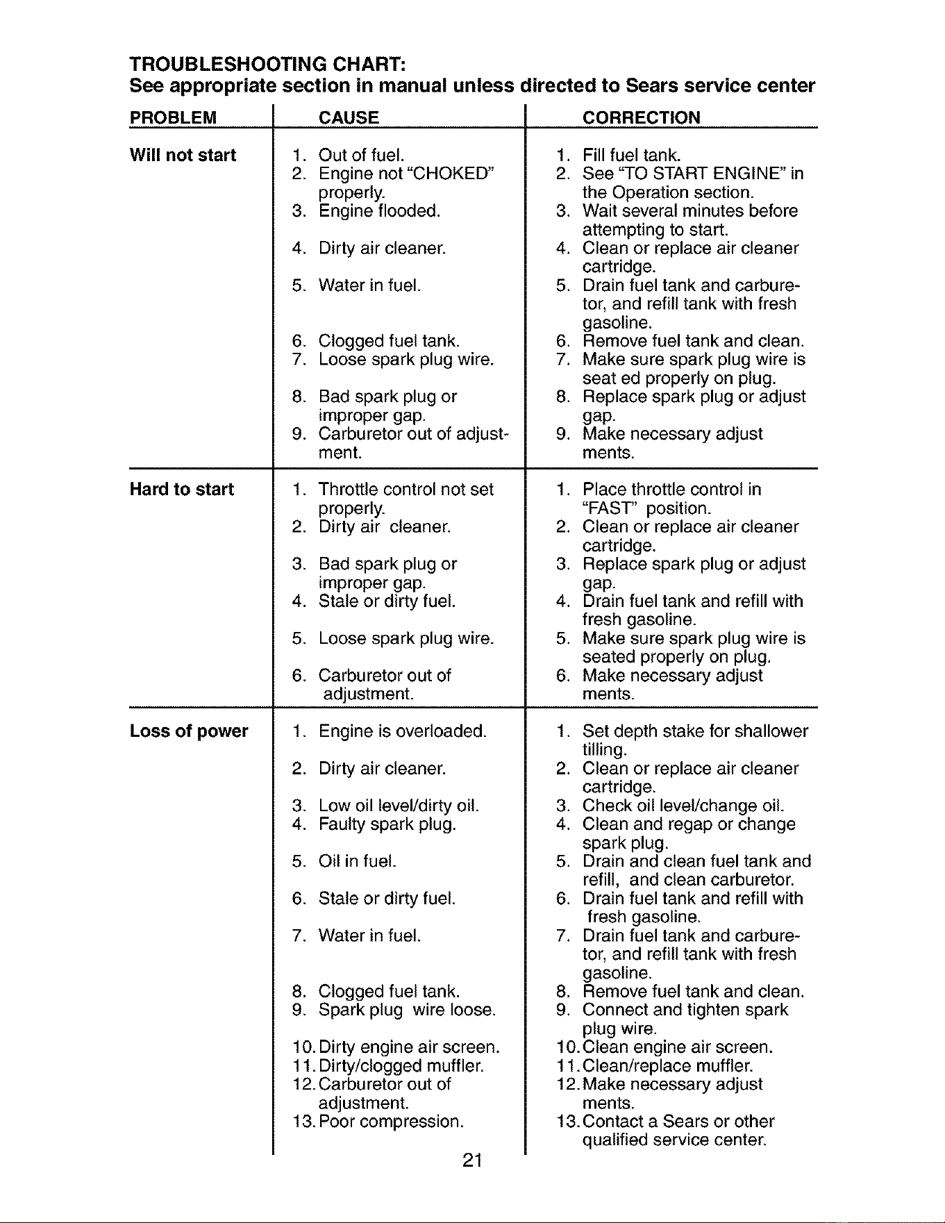
TROUBLESHOOTING CHART:
See appropriate section in manual unless directed to Sears service center
PROBLEM
Will not start
Hard to start
Loss of power
CAUSE
1. Out of fuel.
2. Engine not "CHOKED"
properly.
3. Engine flooded.
4. Dirty air cleaner.
5. Water in fuel.
6. Clogged fuel tank.
7. Loose spark plug wire.
8. Bad spark plug or
improper gap.
9. Carburetor out of adjust-
ment.
1. Throttle control not set
properly.
2. Dirty air cleaner.
3. Bad spark plug or
improper gap.
4. Stale or dirty fuel.
5. Loose spark plug wire.
6. Carburetor out of
adjustment.
1. Engine is overloaded.
2. Dirty air cleaner.
3. Low oil level/dirty oil.
4. Faulty spark plug.
5. Oil in fuel.
6. Stale or dirty fuel.
7. Water in fuel.
8. Clogged fuel tank.
9. Spark plug wire loose.
10. Dirty engine air screen.
11. Dirty/clogged muffler.
12. Carburetor out of
adjustment.
13. Poor compression.
21
CORRECTION
1. Fill fuel tank.
2. See "TO START ENGINE" in
the Operation section.
3. Wait several minutes before
attempting to start.
4. Clean or replace air cleaner
cartridge.
5. Drain fuel tank and carbure-
tor, and refill tank with fresh
gasoline.
6. Remove fuel tank and clean.
7. Make sure spark plug wire is
seat ed properly on plug.
8. Replace spark plug or adjust
gap.
9. Make necessary adjust
ments.
1. Place throttle control in
"FAST' position.
2. Clean or replace air cleaner
cartridge.
3. Replace spark plug or adjust
gap.
4. Drain fuel tank and refill with
fresh gasoline.
5. Make sure spark plug wire is
seated properly on plug.
6. Make necessary adjust
ments.
1. Set depth stake for shallower
tilling.
2. Clean or replace air cleaner
cartridge.
3. Check oil level/change oil.
4. Clean and regap or change
spark plug.
5. Drain and clean fuel tank and
refill, and clean carburetor.
6. Drain fuel tank and refill with
fresh gasoline.
7. Drain fuel tank and carbure-
tor, and refill tank with fresh
gasoline.
8. Remove fuel tank and clean.
9. Connect and tighten spark
plug wire.
10.Clean engine air screen.
11. Clean/replace muffler.
12. Make necessary adjust
ments.
13. Contact a Sears or other
qualified service center.
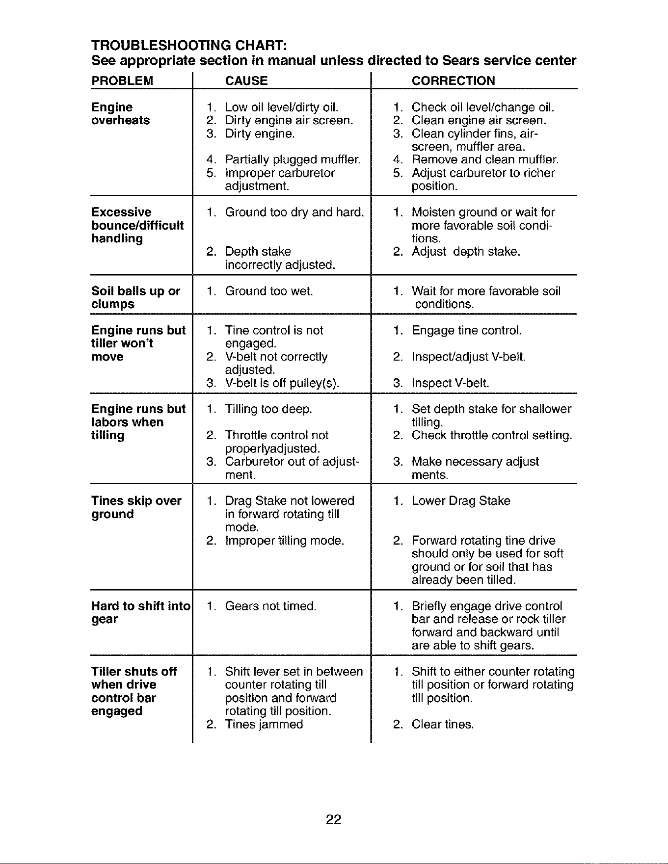
TROUBLESHOOTING CHART:
See appropriate section in manual unless directed to Sears service center
PROBLEM
Engine
overheats
Excessive
bounce/difficult
handling
Soil balls up or
clumps
Engine runs but
tiller won't
move
Engine runs but
labors when
tilling
Tines skip over
ground
CAUSE
1. Low oil level/dirty oil.
2. Dirty engine air screen.
3. Dirty engine.
Hard to shift into
gear
Tiller shuts off
when drive
control bar
engaged
4. Partially plugged muffler.
5. Improper carburetor
adjustment.
1. Ground too dry and hard.
2. Depth stake
incorrectly adjusted.
1. Ground too wet.
.
2.
3.
1.
2.
3.
Tine control is not
engaged.
V-belt not correctly
adjusted.
V-belt is off pulley(s).
Tilling too deep.
Throttle control not
properlyadjusted.
Carburetor out of adjust-
ment.
1. Drag Stake not lowered
in forward rotating till
mode.
2. Improper tilling mode.
1. Gears not timed.
1. Shift lever set in between
counter rotating till
position and forward
rotating till position.
2. Tines jammed
CORRECTION
1. Check oil level/change oil.
2. Clean engine air screen.
3. Clean cylinder fins, air-
screen, muffler area.
4. Remove and clean muffler.
5. Adjust carburetor to richer
position.
1. Moisten ground or wait for
more favorable soil condi-
tions.
2. Adjust depth stake.
1. Wait for more favorable soil
conditions.
1. Engage tine control.
2. Inspect/adjust V-belt.
3. Inspect V-belt.
1. Set depth stake for shallower
tilling.
2. Check throttle control setting.
3. Make necessary adjust
ments.
1. Lower Drag Stake
.
Forward rotating tine drive
should only be used for soft
ground or for soil that has
already been tilled.
.
Briefly engage drive control
bar and release or rock tiller
forward and backward until
are able to shift gears.
1. Shift to either counter rotating
till position or forward rotating
till position.
2. Clear tines.
22
Garantia ....................................................... 23
Reglas de Seguridad ................................... 23
Especificaciones del producto ..................... 25
Montaje ........................................................ 26
Operaci6n .................................................... 29
Programa de Mantenimiento ....................... 35
Mantenimiento ............................................. 35
Servicio y Ajustes ....................................... 37
Almacenamiento .......................................... 41
Identificaci6n de Problemas ........................ 42
Vea el Manual Ingles ............ Ingl6s del DueSo
GARANTIA LIMITADA DE DOS AI_IOS PARA LA CULTIVADORA CRAFTSMAN
Por dos (2) aSos, a partir de la fecha de compra, cuando esta Cultivadora Craftsman se mantenga,
lubrique y afine segSn las instrucciones para la operaci6n y el mantenimiento en el manual del
dueSo, Sears repararA, gratis, todo defecto en el material y la mano de obra.
Esta Garantia no cubre:
• Articulos que se desgastan durante el uso normal tales como los brazos, las bujfas, los filtros de
aire y las correas.
• Reparaciones necesarias debido al abuse o a la negligencia del operador, incluy_ndose a los
cigeeSales doblados y a la falta de mantenimiento del equipo seg=3n las instrucciones que se
incluyen en el manual del dueSo.
• Si la Cultivadora Craftsman se usa para fines de arriendo, esta garantia se aplica solamente por
treinta (30) treintadfas a partir de la fecha de compra.
El Servicio de Garantia esta disponible at devolver la cultivadora Craftsman al centro/departamento
de servicio Sears mAs cercano en los estados unidos.
Esta Garantia se aplica solamente mientras el producto este en uso en los estados unidos. Esta
Garanfia le otorga derechos legales especfficos, y puede que tambi6n tenga otros derechos que
varfan de estado a estado.
SEARS, ROEBUCK AND CO., D/817WA, HOFFMAN ESTATES, IL 60179 U.S.A.
IMPORTANTE: Esta Maquina cortadora es capaz de amputar las manosy los pies y de lanzar
objetos, si no se observan las instrucciones de seguridad siguientes se pueden producir lesiones
graves o la muerte.
ENTRENAMIENTO
• Lea el Manual del Dueff_ocuidadosamente.
Familiarfcese completamente con los
controles y con el uso adecuado del equipo.
Sepa c6mo parar la unidad y desenganchar
los controles rApidamente.
• Nunca permita que los niSos operen el equi-
po. Nunca permita que los adultos operen el
equipo sin los conocimientos adecuados.
• Mantenga el Area de operaci6n despejada de
personas, especialmente niSos pequeSos y
animales dom_sticos.
PREPARACION
• Inspeccione cuidadosamente el Area en
donde se va usar el equipo y remueva los
objetos extrai_os.
• Desenganche todos los embragues y cambie
a neutro antes de hacer arrancar el motor.
• No opere el equipo sin usar ropa exterior
adecuada. Use zapatos que mejoren el equi-
librio en superficies resbalosas.
• Maneje el combustible con cuidado pues es
muy inflamable.
• Use un envase de combustible aprobado.
• Nunca aSada combustible a un motor en
funcionamiento o caliente.
• Llene el estanque de combustible afuera con
mucho cuidado. Nunca llene et estanque de
combustible en un recinto cerrado.
• Vuelva a colocar la tapa det dep6sito de gas-
olina en forma segura y limpie el combustible
derramado antes de volver a arrancar.
• Use cordones de extensi6n y receptAculos,
segtJn las especificaciones del fabricante,
para todas tas unidades con motores de im-
pulsi6n o con motores de arranque el6ctrico.
• Nunca trate de hacer ning_n ajuste mientras
que el motor est6 funcionando (excepto en
los casos especfficamente recomendados
per el fabricante).
OPERACION
• No ponga ni las manos ni los pies cerca o
debajo de las piezas rotatorias.
• Tenga mucho cuidado cuando opere o cruce
entradas para autom6viles de ripio, senderos
o caminos. Est6 aterta en 1oque se refiere a
los peligros escondidos o al trAfico. No lleve
pasajeros.
23
• Despu_s de pegarle a un objeto extra5o,
pare el motor, remueva el atambre de la
bujfa, inspeccione la cultivadora cuidadosa-
mente, para verificar si hay da_os, y repare
el da_o antes de volver a arrancar y operar la
cultivadora.
• Tenga cuidado para evitar resbalarse o
caerse.
• Si la unidad empieza a vibrar anormalmente,
pare et motor y revisela inmediatamente para
verificar la causa. La vibraciSn normalmente
es un aviso de problemas.
• Pare el motor cuando abandone la posici6n
de operaciSn.
• Tome todas tas precauciones posibles cu-
ando deje la mAquina desatendida. Desen-
ganche los brazos, cambie a neutro y pare el
motor.
• Antes de limpiar, reparar e inspeccionar,
apague el motor y asegSrese que todas
las partes en movimiento se han detenido.
Desconecte et alambre de la bujfa, y mant6n-
galo alejado de 6sta para evitar el arranque
por accidente. Desconecte el cord6n en los
motores el_ctricos.
• No haga funcionar el motor en recintos cer-
rados; los gases de escape son peligrosos.
• Nunca opere la cultivadora sin las protec-
clones, y las planchas adecuadas y sin los
demAs dispositivos de seguridad en su lugar.
• Mantenga a los ni_os y a los animates do-
m_sticos alejados.
• No sobrecargue la capacidad de la m&quina,
tratando de cultivar a mucha profundidad,
muy r&pido.
• Nunca opere la m&quina a altas velocidades
en superficies resbalosas. Mire hacia atrAs y
tenga cuidado cuando retroceda.
• Nunca permita la presencia de espectadores
cerca de la unidad.
• Use solamente accesorios y aditamentos
para la cultivadora aprobados por el fabri-
oante.
• Nunca opere la cultivadora sin buena visibili-
dad o luz.
• Tenga cuidado al cultivar en terreno duro.
Los brazos pueden quedarse agarrados en
el suelo e impulsar a la cultivadora hacia
adelante. Si esto sucede, suelte los mangos
y no restrinja la mAquina.
MANTENIMIENTO Y ALMACENAMIEN-
TO
• Mantenga los accesorios y aditamentos de
la mAquina en buenas condiciones para el
funcionamiento.
• Revise las clavijas de seguro, los pernos
de montaje del motor y otros pernos, a
intervatos frecuentes, para verificar si est&n
apretados en forma segura y asegurarse que
el equipo est6 en buenas condiciones de
funcionamiento.
• Nunca guarde la m&quina con combustible
en et estanque de combustible dentro de un
edificio en donde hay fuentes de ignici6n
presentes, tales como calentadores de agua
o del ambiente, secadoras de ropa u otros
artefactos parecidos. Permita que se enfrfe
el motor antes de guardarlo en algt]n lugar
cerrado.
• Siempre refi6rase a las instrucciones en la
gufa del operador para ver los detalles de im-
portancia si la cultivadora va a ser guardada
por un perfodo de tiempo largo.
_,Busque este sfmbolo que sefiala las precau-
clones de seguridad de importancia. Quiere
decir-iiiATENCION!!! iiiESTE ALERTO!!! SU
SEGURIDAD ESTA COMPROMETIDA.
_PRECAUCI(_N: Siempre desconecte el
alambre de la bujia y p6ngalo donde no pueda
entrar en contacto con la bujia, para evitar el
arranque pot accidente, durante la preparaciSn,
el transporte, el ajuste o cuando se hacen
reparaciones.
_ADVERTENCIA: El tubo de escape del
motor, algunos de sus constituyentes y algunos
componentes del vehfculo contienen o despren-
den productos quimicos conocidos en el Estado
de California como causa de c&ncer y defectos
al nacimiento u otros dafios reproductivos.
24
ESPECIFICACIONES DEL PRODUCTO
Capacidad de 4 Cuartos
gasolina: Sin plomo, regular
Aceite(API-SF-SJ): SAE 30 (Sobre 40°F)
(Capacidad: 19oz.) SAE 5w-30 SAE 10w-30
(Debajo 40°F)
Bujia : Champion RC12YC
(Abertura: 0,030")
FELIClTAClONES por la compra de su Culti-
vadora Sears. Ha side diseSada, planificada y
fabricada para darle la mejor confiabilidad y el
mejor rendimiento posible.
En el caso de que se encuentre con cualquier
problema que no pueda solucionar f&cilmente,
haga el favor de ponerse en contacto con un
centro de servicio Sears o con un otro centro
de servicio cualificado. Cuenta con t_cnicos
bien capacitados y competentes con herra-
mientas adecuadas para darle servicio 0 para
reparar su unidad.
Haga el favor de leer y de guardar este manual.
Estas instrucciones le permitir&n montar y man-
tener su cultivadora en forma adecuada. Siem-
pre observe las "REGLAS DE SEGURIDAD?
RESPONSABILIDADES DEL CLIENTE
• Lea y observe las reglas de seguridad.
• Siga un programa regular de mantenimiento,
cuidado y uso de su cultivadora.
• Siga las instrucciones descdtas en las sec-
ciones "Mantenimiento" y "Almacenamiento"
de este Manual del DueSo.
_bADVERTENCIA: Esta unidad viene equipa-
da con un motor de combustiSn interno y no se
debe usar sobre, o cerca, de un terreno no de-
sarrollado cubierto de bosques, de arbustos o
de c6sped, a menos que el sistema de escape
del motor venga equipado con un amortiguador
de chispas que cumpla con las leyes locales 0
estatales (si existen). Si se usa un amortigua-
dor de chispas, el operador debe mantenerlo
en condiciones de trabajo eficientes.
En el estado de California, la ley exige I0 an-
terior (Secci6n 4442 del "California Public Re-
sources Code" [Decreto de Recursos PQblicos
de California]). Otros estados pueden contar
con otras leyes parecidas. Las leyes federales
se aplican en las tierras federales. Su centre
de Servicio m&s cercano tiene disponible amor-
tiguadores de chispas para el silenciador. (Vea
la secciSn de Partes de Repuesto en el manual
Ingl6s del dueiSo.)
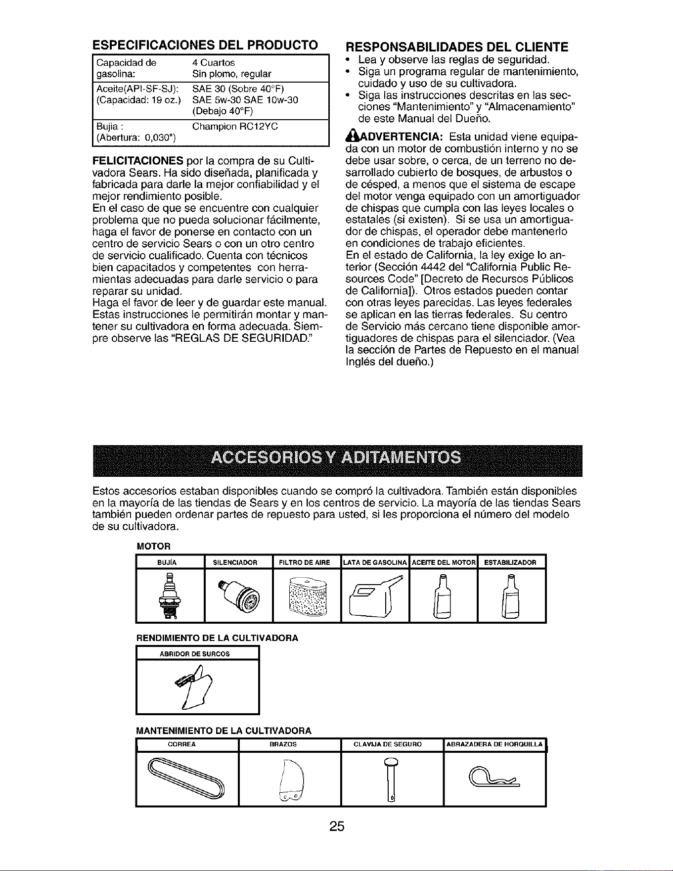
Estos accesorios estaban disponibles cuando se compr6 la cultivadora. Tambi6n est#,n disponibles
en la mayoria de las tiendas de Sears y en los centros de servicio. La mayoria de las tiendas Sears
tambi6n pueden ordenar partes de repuesto para usted, si les proporciona el nt]mero del modelo
de su cultivadora.
MOTOR
BU31A SILENClADOR FILTRO DE AIRE LATA DE GASOLIN/_ ACErFE DEL MOTOR ESTABILIZADOR
RENDIMIENTO DE LA CULTIVADORA
ABRIDOR DE SURCOS
MANTEN|MIENTO DE LA CULT|VADORA
CORREA BRAZES CLAVIJA DE SEGURO ABRAZADERA DE HORQtJlLLA
c
25
Su cultivadora nueva ha sido montada en la f&brica, con la excepci6n de aquellas partes que se
dejaron sin montar per razones de envio. Para asegurarse que la cultivadora operar& en forma
segura y adecuada, todas las partes y los art[culos de ferreteria que monte tienen que estar apre-
tados en forma segura. Use las herramientas correctas, segen sea necesario, para asegurarse de
que queden apretadas en forma segura.
HERRAMIENTAS NECESARIAS PARA
EL MONTAJE
Se le facilitarA el montaje si cuenta con un
juego de llaves de tubo. Se han enumerado los
tama_os est#,ndar de las Ilaves.
(1) Cuchillo para todo uso
(1) Cortador de alambres
(1) Destornillador
(1) Medidor de presi6n de las llantas
(1) Par de alicates
(1) Llave de 9/16"
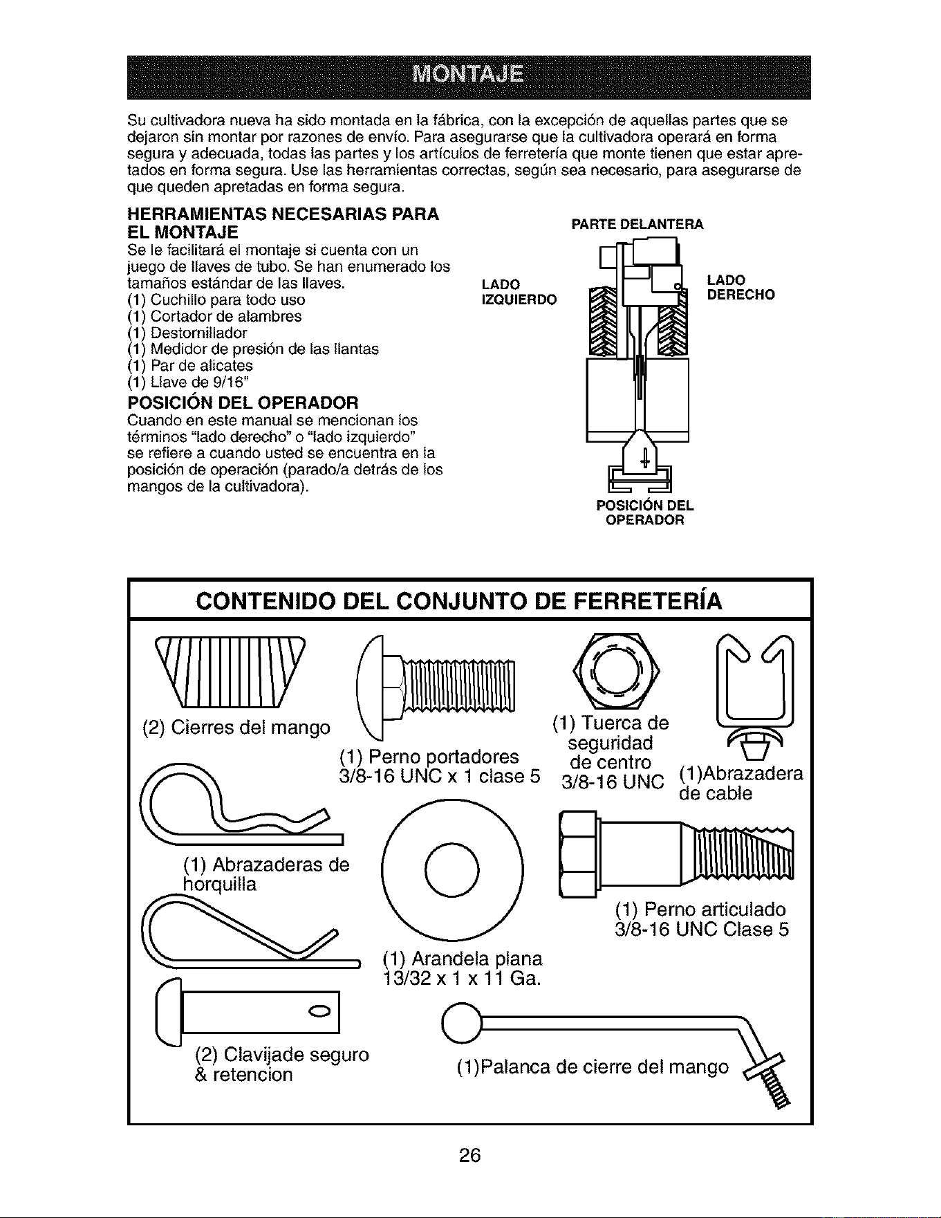
POSICION DEL OPERADOR
Cuando en este manual se mencionan los
t6rminos "lade derecho" o "lado izquierdo°
se refiere a cuando usted se encuentra en la
posici6n de operaci6n (parado/a detrAs de los
mangos de la cultivadora).
LADO
IZQUIERDO
PARTE DELANTERA
LADO
DERECHO
POSICION DEL
OPERADOR
CONTENIDO DEL CONJUNTO DE FERRETERiA
(2) Cierres del mango
(1) Pemo portadores
_ 3/8-16 UNC x 1 clase 5
I
(1) Abrazaderas de / (" "_ /
_ horquilla
, (1) Arandela plana
°l
(2) Clavijade seguro
& retencion
13/32 x 1 x 11 Ga.
43
(1) Tuerca de
seguridad
de centro
3/8-16 UNC
(1)Abrazadera
de cable
D
(1) Perno articulado
3/8-16 UNC Clase 5
0
(1)Palanca de cierre del mango
26
DESEMPAQUE DE LA CAJA DE
CARTON
_PRECAUCI(_N: Tenga cuidado con las
grapas expuestas cuando maneje o deseche
los materiales de la caja de cart6n.
IMPORTANTE: Cuando desempaque y monte
la cultivadora, tenga cuidado de no estirar o
enredar los cables.
1. AI mismo tiempo que se sujeta el conjunto
del mange, corte las ligaduras del cable que
aseguran el conjunto del mango al bastidor
superior y a la estaca de profundidad. Per-
mita que el conjunto del mango descanse
en la cultivadora.
2. Remueva el bastidor superior de la caja de
cart6n.
3. Lentamente, saque el conjunto del mango
hacia arriba y p6ngalo en la parte superior
de la caja de cart6n.
4. Corte ta esquina det lado derecho delantera
y la trasera de la caja de cart6n. Tienda
en el suelo la pared lateral de la caja de
cart6n.
5. Remueva el material de empaque del con-
junto del mango.
Varilla de Cambio
I Conjunto del
I Mango
d
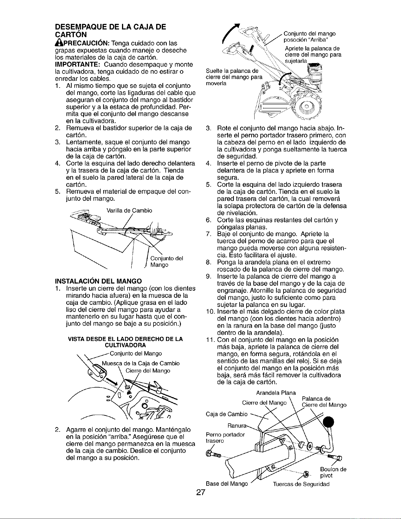
INSTALACI()N DEL MANGO
1. Inserte un cierre del mango (con los dientes
mirando hacia afuera) en la muesca de la
caja de cambio. (Aplique grasa en el lado
liso del cierre del mango para ayudar a
mantenerlo en su lugar hasta que el con-
junto del mango se baje a su posici6n.)
VISTA DESDE EL LADO DERECHO DE LA
CULTIVADORA
. ,_Conjunto del Mango
esca de la Caja de Cambio
Cierre del Mango
Suelte la
cierre del mango para
moverla
unto del mango
posoci6n "Arriba"
Apriete la palanca de
cierre del mango para
3. Rote el conjunto del mango hacia abajo. In-
serte el perno portador trasero primero, con
la cabeza del perno en el lado izquierdo de
la cultivadora y ponga sueltamente la tuerca
de seguridad.
4. Inserte el perno de pivote de la parte
delantera de la placa y apriete en forma
segura.
5. Corte la esquina del lado izquierdo trasera
de la caja de cart6n. Tienda en el suelo la
pared trasera del cart6n, la cual remover#,
la solapa protectora de cart6n de la defensa
de nivelaci6n.
6. Corte las esquinas restantes del cart6n y
p6ngalas planas.
7. Baje el conjunto de mango. Apriete la
tuerca del perno de acarreo para que el
mango pueda moverse con alguna resisten-
cia. Esto facilitara el ajuste.
8. Ponga la arandeta plana en el extremo
roscado de la palanca de cierre det mango.
9. Inserte la palanca de cierre del mango a
trav_s de la base del mango y de la caja de
engranaje. Atornille la palanca de seguridad
del mango, justo Io suficiente como para
sujetar la palanca en su lugar.
10. Inserte el m_s delgado cierre de color plata
del mango (con los dientes hacia adentro)
en la ranura en la base del mango Gusto
dentro de la arandeta).
11. Con el conjunto del mango en ta posici6n
mAs baja, apriete la palanca de cierre del
mango, en forma segura, rot&ndola en el
sentido de las manillas del reloj. Si se deja
el conjunto del mango en la posici6n m&s
baja, ser& m&s f_,cil remover la cultivadora
de la caja de cart6n.
Arandela Plana
Palanca de
Cierre del Mango Cierre del Mango
Caja de Cambio
2.
Agarre el conjunto del mango. Mant6ngalo
en la posici6n "arriba." Aseg0rese que el Perno portador
trasero
cierre del mango permanezca en la muesca /
de la caja de cambio. Destice el conjunto
del mango a su posici6n.
Base del Mango
27
Boulonde
pivot
Tuercas de Seguridad
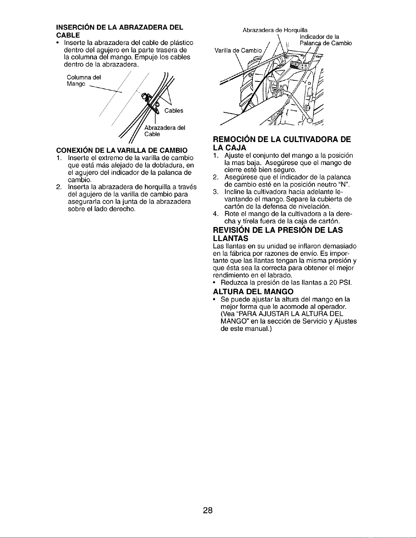
INSERCI(_N DE LA ABRAZADERA DEL
CABLE
• Inserte la abrazadera del cable de plastico
dentro del agujero en la parte trasera de
la columna det mango. Empuje los cables
dentro de la abrazadera.
Columna del
Mango
Abrazadera de Horquilla
lndicador de la
de Cambio
Varilla de Cambio
Cables
Abrazadera del
Cable
CONEXI(_N DE LA VARILLA DE CAMBIO
1. Inserte el extremo de la vadlla de cambio
que est& m&s alejado de la dobladura, en
el agujero del indicador de la palanca de
cambio.
2. Inserta la abrazadera de horquilla a trav6s
del agujero de la varilla de cambio para
asegurarla con la junta de la abrazadera
sobre el lado derecho.
REMOClON DE LA CULTIVADORA DE
LA CAJA
1. Ajuste el conjunto del mango a la posici6n
lamas baja. AsegSrese que el mango de
cierre est6 bien seguro.
2. Asegt]rese que el indicador de la palanca
de cambio est6 en la posici6n neutro "N'.
3. Incline la cultivadora hacia adelante le-
vantando el mango. Separe la cubierta de
cart6n de la defensa de nivelaci6n.
4. Rote el mango de la cultivadora a la dere-
cha y tirela fuera de la caja de cart6n.
REVISION DE LA PRESION DE LAS
LLANTAS
Las llantas en su unidad se inflaron demasiado
en la fAbrica per razones de envio. Es impor-
tante que tas Ilantas tengan la misma presi6n y
que 6sta sea la correcta para obtener el meier
rendimiento en el labrado.
• Reduzca la presi6n de las llantas a 20 PSI.
ALTURA DEL MANGO
• Se puede ajustar la altura del mango en la
mejor forma que le acomode al operador.
(Vea "PARA AJUSTAR LA ALTURA DEL
MANGO" en la secci6n de Servicio y Ajustes
de este manual.)
28
CONOZCA SU CULTIVADORA
LEA ESTE MANUAL DEL DUEI_IO Y LAS REGLAS DE SEGURIDAD ANTES DE OPERAR SU
CULTIVADORA
Compare las ilustraciones con su cultivadora para familiarizarse con la ubicaci6n de los diversos
controles y ajustes. Guarde este manual para futura referencia.
LABOREO LABOREO
II/_ N A_ENCJOt40 MOTOR ESTRA_GU COM_
MARCHA N£UTRO REV_S AOVERT£NCiA £NCENDIDO APAGADO £ACK_N £UST_BLE
HACEA
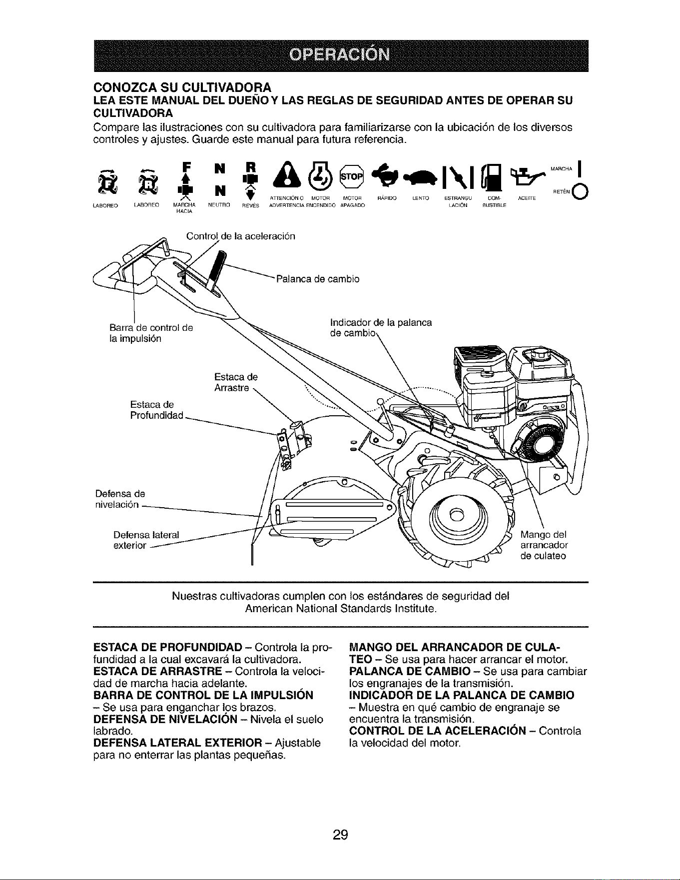
Control de la aceleraci6n
Palanca de cambio
Barra de control de
la impulsi6n
Indicador de la palanca
Estaca de
Arrastre
Estaca de
Defensa de
Defensa lateral
exterior
Mango del
arrancador
de culateo
Nuestras cultivadoras cumplen con los estAndares de seguridad del
American National Standards Institute.
ESTACA DE PROFUNDIDAD - Controla la pro-
fundidad a la cual excavar& la cultivadora.
ESTACA DE ARRASTRE - Controla la veloci-
dad de marcha hacia adelante.
BARRA DE CONTROL DE LA IMPULSION
- Se usa para enganchar los brazos.
DEFENSA DE NIVELACION - Nivela el suelo
labrado.
DEFENSA LATERAL EXTERIOR - Ajustable
para no enterrar las plantas pequeSas.
MANGO DEL ARRANCADOR DE CULA-
TEO - Se usa para hacer arrancar el motor.
PALANCA DE CAMBIO - Se usa para cambiar
los engranajes de la transmisi6n.
INDICADOR DE LA PALANCA DE CAMBIO
- Muestra en qu6 cambio de engranaje se
encuentra la transmisi6n.
CONTROL DE LA ACELERACI(_N - Controla
la velocidad del motor.
29
La operaci6n de cualquier cultivadora puede hacer que salten objetos extrafios den-
tro de sus ojos, 1oque puede producir dafios graves en 6stos. Siempre use anteojos
de seguridad o protecciones para los ojos antes de hacer arrancar su cultivadora o
mientras est6 labrando con _lla. Recomendamos gafas de seguridad o una mAs-
cara de visi6n amplia de seguridad usada sobre las gafas.
COMO USAR SU CULTIVADORA
Sepa c6mo operar todos los controles antes de
agregar combustible y aceite o antes de tratar
de hacer arrancar el motor.
PARADA
BRAZOSY LA IMPULSI(_N
1. Suelte la barra de control de la impulsi6n
para parar el movimiento.
2. Mueva la palanca de cambio a la posici6n
de neutro ("N').
MOTOR
• Mueva el control de la aceleraci6n a la
posici6n de "PARADA" (STOP). Si equipado
con un interruptor de parada, mueva el inter-
ruptor a la posici6n de "PARADA" (STOP).
AMISO: Nunca use la estrangulaci6n para parar
el motor.
5. Sujete la barra de control de la impulsi6n en
contra del mango para hacer arrancar en
movimiento a la cultivadora.
ES DIF|CIL CAMBIAR LAS MARCHAS
• Enganche lentamente la barra de control de
la transmisi6n y suelte o bascule la cultiva-
dora hacia adelante y hacia atr&s hasta que
sea posible cambiar las marchas.
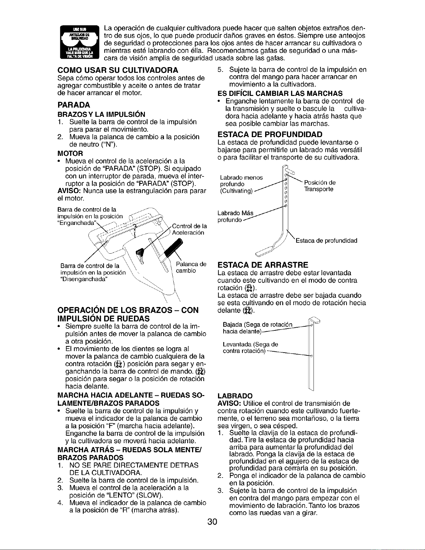
ESTACA DE PROFUNDIDAD
La estaca de profundidad puede levantarse o
bajarse para permitirle un labrado mAs versatil
o para facilitar el transporte de su cultivadora.
Labrado menos
profundo
(Cultivating)
Transporte
Barra de control de la
impulsi6n en la posici6n
"Enganchada",
,Control de la
Aceleraci6n
Labrado MAS
profundo
profundidad
Palanca deBarra de control de la \ cambio
impulsi6n en la posici6n \
"Disenganchada"
OPERACION DE LOS BRAZOS - CON
IMPULSION DE RUEDAS
• Siempre suelte la barra de control de la im-
pulsi6n antes de mover la palanca de cambio
a otra posici6n.
• El movimiento de los dientes se togra al
mover la palanca de cambio cuatquiera de la
contra rotaci6n (_) posici6n para segar y en-
ganchando la barra de control de mando. (_;)
posici6n para segar o la posici6n de rotaci6n
hacia delante.
MARCHA HACIA ADELANTE - RUEDAS SO-
LAMENTE/BRAZOS PARADOS
• Suelte la barra de control de ta impulsi6n y
mueva el indicador de la palanca de cambio
a la posici6n "F" (marcha hacia adelante).
Enganche la barra de control de la impulsi6n
y la cultivadora se mover_ hacia adelante.
MARCHA ATRAS - RUEDAS SOLA MENTE/
BRAZOS PARADOS
1. NO SE PARE DIRECTAMENTE DETRAS
DE LA CULTIVADORA.
2. Suelte la barra de control de la impulsi6n.
3. Mueva el control de la aceleraci6n a la
posici6n de "LENTO" (SLOW).
4. Mueva et indicador de la palanca de cambio
a la posici6n de "R" (marcha atrAs).
ESTACA DE ARRASTRE
La estaca de arrastre debe estar tevantada
cuando este cultivando en el modo de contra
rotaci6n (_).
La estaca de arrastre debe ser bajada cuando
se esta cultivando en el modo de rotaci6n hecia
delante (_).
Bajada (Sega de rotaciS_._._._._
hacia delante)--------
Levantada(Sega de
contra rotaci6n)
30
LABRADO
AVISO: Utilice el control de transmisi6n de
contra rotaci6n cuando este cultivando fuerte-
mente, o el terreno sea montafioso, o la tierra
sea virgen, o sea c_sped.
1. Suelte la clavija de la estaca de profundi-
dad. Tire la estaca de profundidad hacia
arriba para aumentar la profundidad del
labrado. Ponga la clavija de la estaca de
profundidad en el agujero de la estaca de
profundidad para cerrarla en su posici6n.
2. Ponga el indicador de la palanca de cambio
en la posici6n.
3. Sujete la barra de control de la impulsi6n
en contra del mango para empezar con el
movimiento de labraci6n. Tanto los brazos
como las ruedas van a girar.
4. Muevaelcontroldelaaceleraci6nala
posici6nde"R,_,PIDO"(FAST)paraun
tabradoprofundo.
IMPORTANTE:Siempresueltelabarradecon-
troldelaimpulsi6nantesdemoverlapalanca
decambioaotraposici6n.
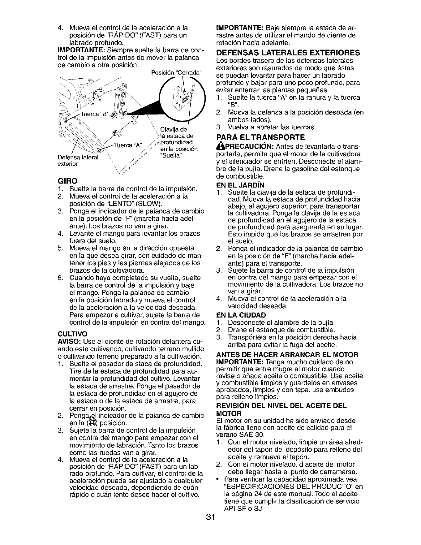
Posici6n"Cerrada"
\
Clavija de
\\ la estaca de
Defensa lateral
exterior
en la posici6n
"Suelta"
GIRO
1. Suelte la barra de control de la impulsi6n.
2. Mueva el control de la aceleraci6n a la
posici6n de "LENTO" (SLOW).
3. Ponga el indicador de la palanca de cambio
en la posici6n de "F" (marcha hacia adel-
ante). Los brazos no van a girar.
4. Levante el mango para levantar los brazos
fuera del suelo.
5. Mueva el mango en la direcci6n opuesta
en la que desea girar, con cuidado de man-
tener los pies y las piernas atejados de los
brazos de la cultivadora.
6. Cuando haya completado su vuelta, suelte
la barra de control de la impulsi6n y baje
el mango. Ponga la palanca de cambio
en la posici6n labrado y mueva el control
de la aceleraci6n a la velocidad deseada.
Para empezar a cultivar, sujete la barra de
control de la impulsi6n en contra del mango.
CULTIVO
AVISO: Use el diente de rotaci6n delantera cu-
ando este cultivando, cultivando terreno mullido
o cultivando terreno preparado a la cultivaci6n.
1. Suelte el pasador de staca de profundidad.
Tire de la estaca de profundidad para au-
mentar la profundidad del cultivo. Levantar
la estaca de arrastre. Ponga el pasador de
la estaca de profundidad en el agujero de
la estaca o de la estaca de arrastre, para
cerrar en posici6n.
2. Pongatel indicador de la palanca de cambio
en la (;_q;)posici6n.
3. Sujete la barra de control de la impulsi6n
en contra del mango para empezar con et
movimiento de labraci6n. Tanto los brazos
como las ruedas van a girar.
4. Mueva el contrgl de la aceleraci6n a la
posici6n de "RAPIDO" (FAST) para un lab-
rado profundo. Para cultivar, el control de la
aceleraci6n puede ser ajustado a cualquier
velocidad deseada, dependiendo de cu&n
r&pido o cu&n lento desee hacer el cultivo.
31
IMPORTANTE: Baje siempre la estaca de ar-
rastre antes de utilizar el mando de diente de
rotaci6n hacia adelante.
DEFENSAS LATERALES EXTERIORES
Los bordes trasero de las defensas laterates
exteriores son rasurados de modo que _stas
se puedan levantar para hacer un labrado
profundo y bajar para uno poco profundo, para
evitar enterrar las plantas pequefias.
1. Suelte la tuerca "A" en la ranura y la tuerca
"B'.
2. Mueva la defensa a la posici6n deseada (en
ambos lados).
3. Vuelva a apretar las tuercas.
PARA EL TRANSPORTE
_I_PRECAUOI(_N: Antes de levantarla o trans-
portarla, permita que el motor de la cultivadora
y el silenciador se enfrfen. Desconecte el alam-
bre de la bujia. Drene la gasolina del estanque
de combustible.
EN EL JARD[N
1. Suelte la clavija de ta estaca de profundi-
dad. Mueva la estaca de profundidad hacia
abajo, al agujero superior, para transportar
la cultivadora. Ponga la clavija de la estaca
de profundidad en el agujero de la estaca
de profundidad para asegurarla en su lugar.
Esto impide que los brazos se arrastren por
el suelo.
2. Ponga el indicador de la palanca de cambio
en la posici6n de "F" (marcha hacia adel-
ante) para el transporte.
3. Sujete la barra de control de la impulsi6n
en contra del mango para empezar con el
movimiento de la cultivadora. Los brazos no
van a girar.
4. Mueva el control de la aceleraci6n a la
velocidad deseada.
EN LA ClUDAD
1. Desconecte el alambre de la bujfa.
2. Drene el estanque de combustible.
3. Transp6rtela en la posici6n derecha hacia
arriba para evitar la fuga del aceite.
ANTES DE HACER ARRANCAR EL MOTOR
IMPORTANTE: Tenga mucho cuidado de no
permitir que entre mugre al motor cuando
revise o afiada aceite o combustible. Use aceite
y combustible limpios y guardelos en envases
aprobados, limpios y con tapa. use embudos
para relleno limpios.
REVISI(_N DEL NIVEL DEL ACEITE DEL
MOTOR
El motor en su unidad ha sido enviado desde
la f_,brica lleno con aceite de calidad para el
verano SAE 30.
1. Con el motor nivelado, limpie un &rea aired-
edor del tap6n del dep6sito para relleno del
aceite y remueva et tap6n.
2. Con el motor nivelado, d aceite del motor
debe Ilegar hasta el punto de derramarse.
• Para verificar la capacidad aproximada yea
"ESPECIFICACIONES DEL PRODUCTO" en
la p&gina 24 de este manual. Todo el aceite
tiene que cumplir la clasificaci6n de servicio
API SF o SJ.
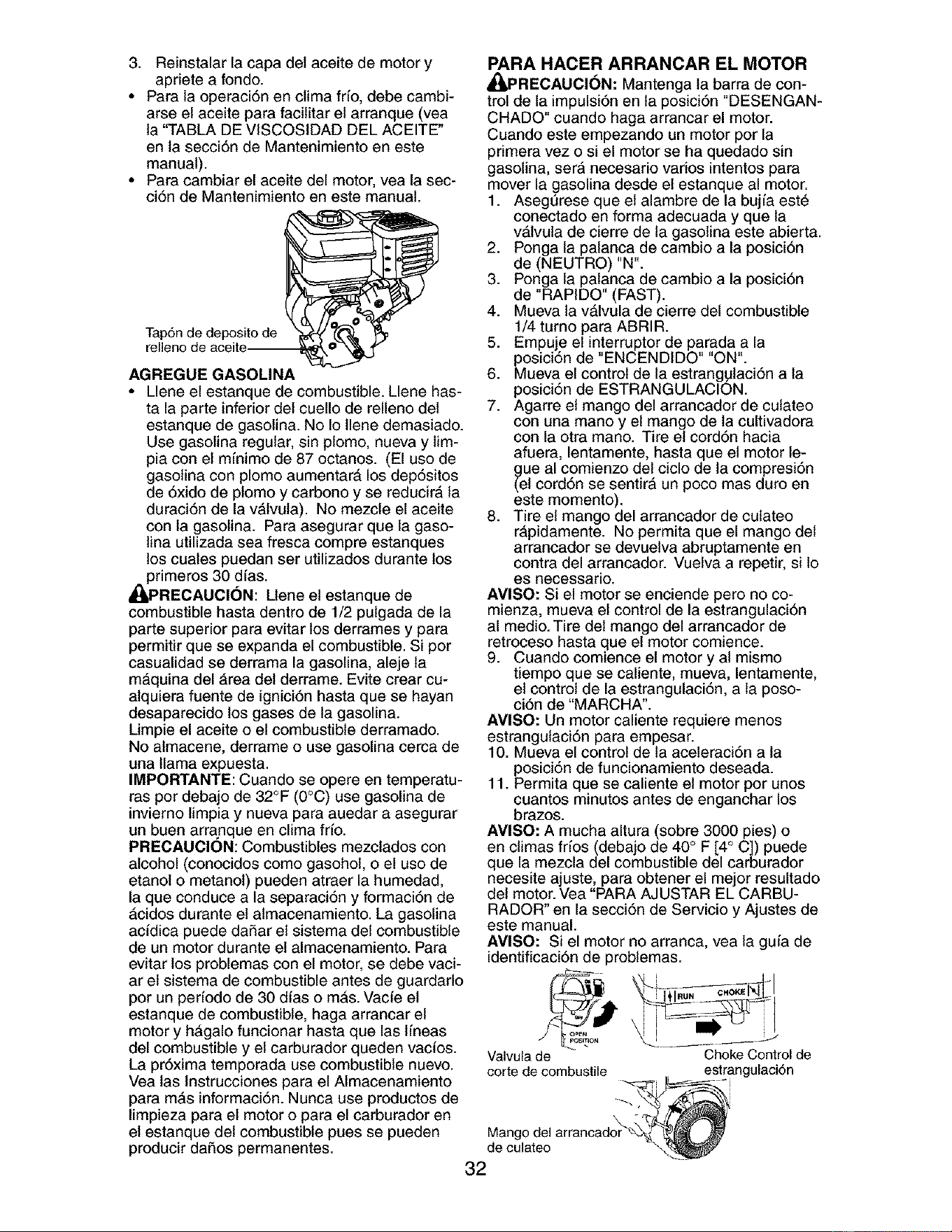
3. Reinstalarlacapadelaceitedemotory
aprietea fondo.
• Paralaoperaci6nenclimafifo,debecambi-
arseelaceiteparafacilitarelarranque(vea
la"TABLADEVISCOSIDADDELACEITE"
entasecci6ndeMantenimientoeneste
manual).
• Paracambiarelaceitedelmotor,yealasec-
ci6ndeMantenimientoenestemanual.
Tap6n de deposito de
relleno de aceite--
AGREGUE GASOLINA
• Llene el estanque de combustible. Llene has-
ta la parte inferior del cuello de relleno del
estanque de gasolina. No Io llene demasiado.
Use gasolina regular, sin plomo, nueva y lim-
pia con el mfnimo de 87 octanos. (El uso de
gasolina con plomo aumentar& los dep6sitos
de 6xido de plomo y carbono y se reducirA la
duraci6n de la vAtvula). No mezcle el aceite
con la gasolina. Para asegurar que la gaso-
lina utilizada sea fresca compre estanques
los cuates puedan ser utilizados durante los
primeros 30 dfas.
A(_PREOAUCION: Llene et estanque de
combustible hasta dentro de 1/2 pulgada de la
parte superior para evitar los derrames y para
permitir que se expanda el combustible. Si por
casualidad se derrama la gasolina, aleje ta
m_quina del Area del derrame. Evite crear cu-
alquiera fuente de ignici6n hasta que se hayan
desaparecido los gases de la gasolina.
Umpie el aceite o el combustible derramado.
No almacene, derrame o use gasolina cerca de
una llama expuesta.
IMPORTANTE: Cuando se opere en temperatu-
ras por debajo de 32°F (0°C) use gasolina de
invierno limpia y nueva para auedar a asegurar
un buen arranque en clima fifo.
PRECAUCION: Combustibles mezclados con
alcohol (conocidos como gasohol, o el uso de
etanol o metanol) pueden atraer la humedad,
la que conduce a la separaci6n y formaci6n de
_cidos durante el almacenamiento. La gasolina
acidica puede daSar el sistema det combustible
de un motor durante el almacenamiento. Para
evitar los problemas con el motor, se debe vaci-
ar el sistema de combustible antes de guardarlo
per un perfodo de 30 dias o mAs. Vacie el
estanque de combustible, haga arrancar el
motor y hAgalo funcionar hasta que las lfneas
del combustible y el carburador queden vacios.
La pr6xima temporada use combustible nuevo.
Vea tas Instrucciones para el Almacenamiento
para mAs informaci6n. Nunca use productos de
limpieza para el motor o para el carburador en
el estanque det combustible pues se pueden
producir daSos permanentes.
PARA HACER ARRANCAR EL MOTOR
_PRECAUCI6N: Mantenga la barra de con-
trol de la impulsi6n en ta posici6n "DESENGAN-
CHADO" cuando haga arrancar el motor.
Cuando este empezando un motor pot la
primera vez o si el motor se ha quedado sin
gasolina, serA necesario vados intentos para
mover la gasolina desde el estanque al motor.
1. Asegt]rese que el alambre de la bujfa est6
conectado en forma adecuada y que la
v_,lvula de cierre de la gasolina este abierta.
2. Ponga la palanca de cambio a la posici6n
de (NEUTRO) "N".
3. Ponga la palanca de cambio a la posici6n
de "RAPIDO" (FAST).
4. Mueva la v&lvula de cierre del combustible
1/4 turno para ABRIR.
5. Empuje el interrupter de parada a la
posici6n de "ENCENDIDO" "ON".
6. Mueva el control de la estrang#laci6n a la
posici6n de ESTRANGULACION.
7. Agarre el mango del arrancador de culateo
con una mano y el mango de la cultivadora
con la otra mano. Tire el cord6n hacia
afuera, lentamente, hasta que el motor le-
gue al comienzo del ciclo de la compresi6n
(el cord6n se sentirA un poco mas duro en
este momento).
8. Tire el mango del arrancador de culateo
rApidamente. No permita que el mango del
arrancador se devuelva abruptamente en
contra del arrancador. Vuelva a repetir, si 1o
es necessario.
AMISO: Si el motor se enciende pero no co-
mienza, mueva el control de la estrangulaci6n
al medio. Tire del mango del arrancador de
retroceso hasta que el motor comience.
9. Cuando comience el motor y al mismo
tiempo que se caliente, mueva, lentamente,
el control de la estrangulaci6n, a la poso-
ci6n de "MARCHA'.
AMISO: Un motor caliente requiere menos
estrangulaci6n para empesar.
10. Mueva el control de la aceleraci6n a ta
posici6n de funcionamiento deseada.
11. Permita que se caliente el motor por unos
cuantos minutes antes de enganchar los
brazos.
AVlSO: A mucha altura (sobre 3000 pies) o
en climas fr[os (debajo de 40° F [4 ° C]) puede
que la mezcla del combustible del carburador
necesite ajuste, para obtener el meier resultado
del motor. Vea "PARA AJUSTAR EL CARBU-
RADOR" en la secci6n de Servicio y Ajustes de
este manual.
AVlSO: Si el motor no arranca, vea la guia de
identificaci6n de problemas.
open
Valvula de
corte de combustile
Choke Control de
estrangulaci6n
Mango del arrancad_'
de culateo
32
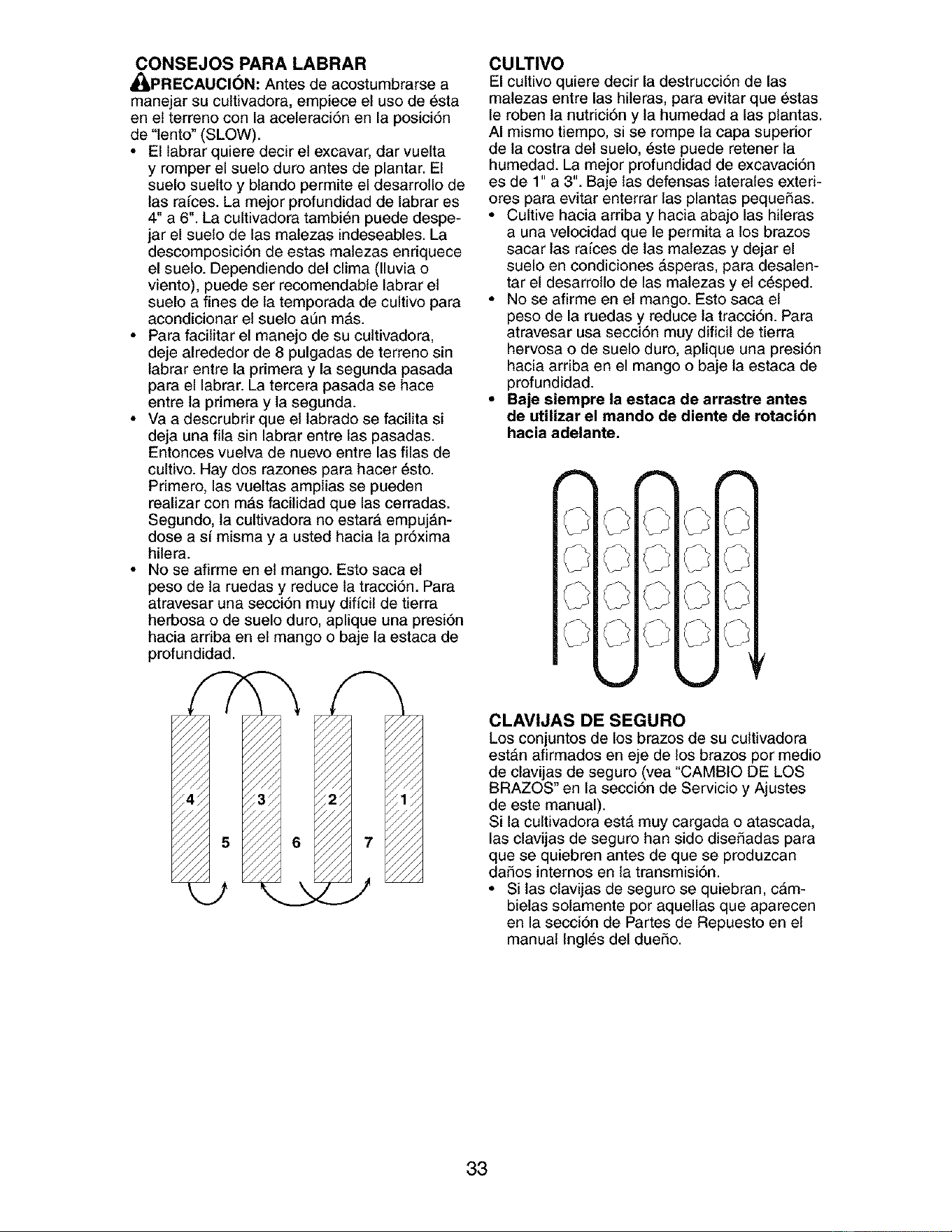
CONSEJOS PARA LABRAR
_PRECAUCI(_N: Antes de acostumbrarse a
manejar su cultivadora, empiece el use de _sta
en et terreno con la aceleraci6n en la posici6n
de "lento" (SLOW).
• El labrar quiere decir el excavar, dar vuelta
y romper el suelo duro antes de plantar. El
suelo suelto y blando permite el desarrollo de
las rafces. La meier profundidad de labrar es
4" a 6". La cultivadora tambi_n puede despe-
jar el suelo de las malezas indeseables. La
descomposici6n de estas matezas enriquece
el sueto. Dependiendo del clima (lluvia o
viento), puede ser recomendable labrar el
suelo a fines de la temporada de cultivo para
acondicionar el suelo a_n m#,s.
• Para facilitar el manejo de su cultivadora,
deje alrededor de 8 pulgadas de terreno sin
labrar entre la primera y la segunda pasada
para el labrar. La tercera pasada se hace
entre la primera y la segunda.
• Va a descrubrir que el labrado se facilita si
deja una ilia sin labrar entre las pasadas.
Entonces vuelva de nuevo entre las filas de
cultivo. Hay dos razones para hacer _sto.
Primero, las vueltas amplias se pueden
realizar con m_,s facilidad que las cerradas.
Segundo, la cultivadora no estar_, empuj#,n-
dose a sf misma y a usted hacia la pr6xima
hilera.
• No se afirme en el mango. Esto saca el
peso de ta ruedas y reduce la tracci6n. Para
atravesar una secci6n muy diffcil de tierra
herbosa o de suelo duro, aplique una presi6n
hacia ardba en el mango o baje la estaca de
profundidad.
7
CULTIVO
El cultivo quiere decir la destrucci6n de las
malezas entre las hileras, para evitar que _stas
le roben la nutrici6n y la humedad alas plantas.
AI mismo tiempo, si se rompe la capa superior
de la costra det suelo, 6ste puede retener la
humedad. La mejor profundidad de excavaci6n
es de 1" a 3". Baje las defensas laterales exteri-
ores para evitar enterrar las plantas pequeSas.
• Cultive hacia arriba y hacia abajo las hileras
a una velocidad que le permita a los brazos
sacar las rafces de las malezas y dejar el
suelo en condiciones &speras, para desaten-
tar el desarrollo de las malezas y el c_sped.
• No se afirme en et mango. Esto saca el
peso de la ruedas y reduce la tracci6n. Para
atravesar usa secci6n muy dificil de tierra
hervosa o de suelo duro, aplique una presi6n
hacia arriba en el mango o baje la estaca de
profundidad.
• Baje siempre la estaca de arrastre antes
de utilizar el mando de diente de rotacion
hacia adelante.
CLAVIJAS DE SEGURO
Los conjuntos de los brazes de su cultivadora
est&n afirmados en eje de los brazes per medio
de ctavijas de seguro (vea "CAMBIO DE LOS
BRAZOS" en la secci6n de Servicio y Ajustes
de este manual).
Si la cultivadora est& muy cargada o atascada,
las clavijas de seguro han side dise_adas para
que se quiebren antes de que se produzcan
da_os internos en la transmisi6n.
• Si las clavijas de seguro se quiebran, c&m-
bielas solamente per aquellas que aparecen
en la secci6n de Partes de Repuesto en el
manual Ingles del dueSo.
33
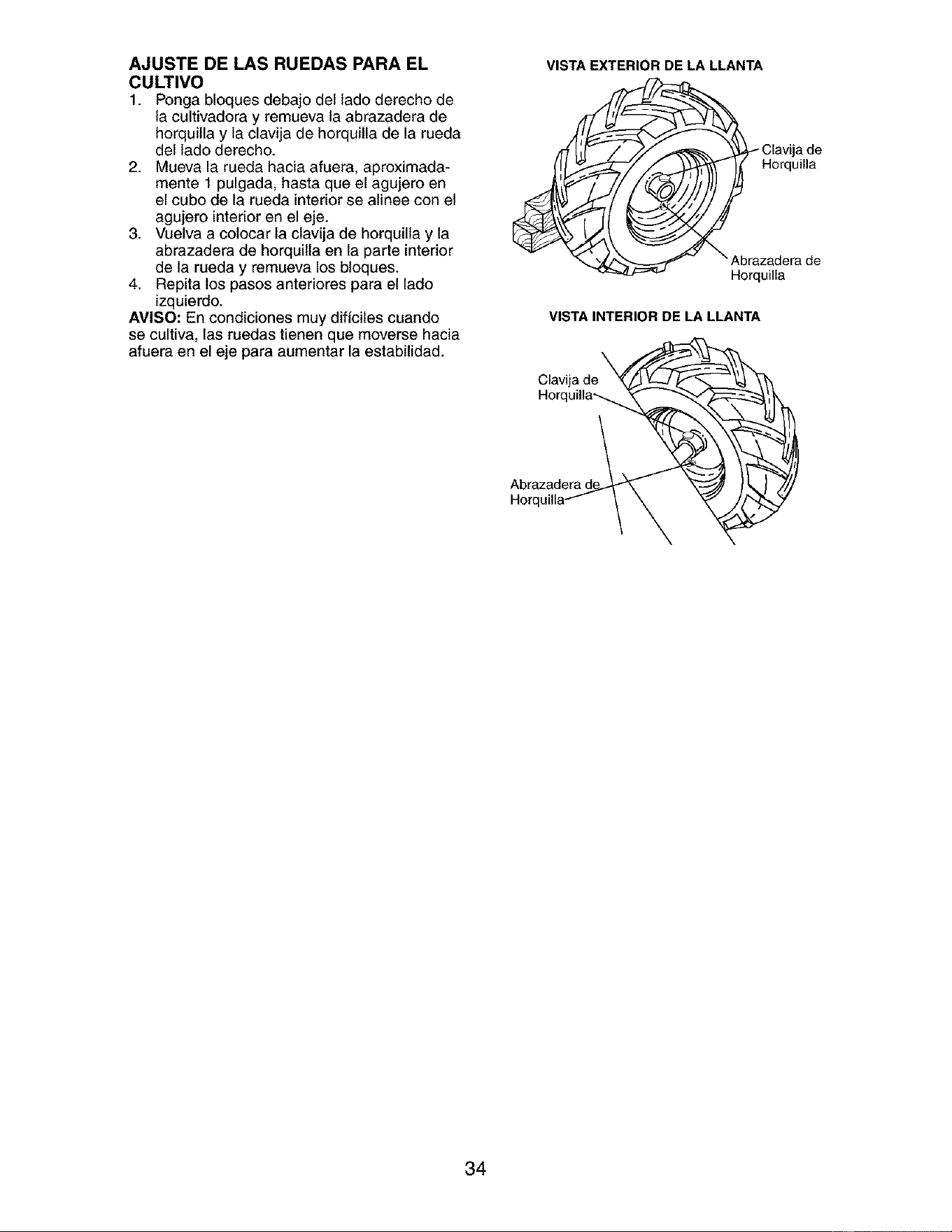
AJUSTE DE LAS RUEDAS PARA EL
CULTIVO
1. Ponga bloques debajo del lado derecho de
la cultivadora y remueva la abrazadera de
horquilla y la clavija de horquilla de la rueda
del lade derecho.
2. Mueva la rueda hacia afuera, aproximada-
mente 1 pulgada, hasta que el agujero en
el cubo de la rueda interior se atinee con el
agujero interior en el eje.
3. Vuelva a colocar la clavija de horquilla y la
abrazadera de horquilla en la parte interior
de la rueda y remueva los bloques.
4. Repita los pasos anteriores para el lado
izquierdo.
AMISO: En condiciones muy dificiles cuando
se cultiva, las ruedas tienen que moverse hacia
afuera en el eje para aumentar la estabilidad.
VISTAEXTERIOR DE LA LLANTA
_ lavija de
Horquilla
VISTA INTERIOR DE LA LLANTA
Clavija de
Horquilla_
Abrazadera d
Horql
34
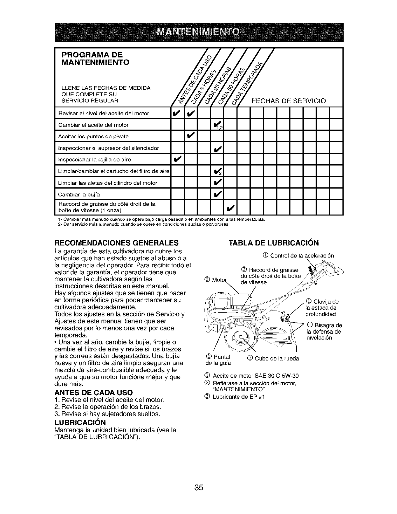
PROGRAMA DE
MANTENIMIENTO
LLENE LAS FECHAS DE MEDIDA
QUE COMPLETE SU
SERVICtO REGULAR
Revisar el nivel del aceite del motor _ Ill
Cambiar el aceite del motor 11_T2
Aceitar los puntos de pivote
lnspeccionar el supresor del silenciador I_
lnspeccionar la rejilla de aire I_
Y
FECHAS DE SERVICIO
Limpiar/cambiar el cartucho del flltro de aire 1_2
Limpiar las aletas del cilindro del motor II S
Cambiar la bujfa ll_
Raccord de graisse du c6t6 droit de la
bo_'te de vitesse (1 onza) I_
1- Cambi_r mas menudo cu_ndo se opere bajo carga pesada o en ambientes con altas temperaturas.
2- Dar sefvicio mas a menudo ouando se opere en condiciones sucias o potvorosas
RECOMENDACIONES GENERALES
La garant/a de esta cultivadora no cubre los
artfculos que han estado sujetos at abuso o a
la negligencia del operador. Para recibir todo el
valor de la garantfa, el operador tiene que
mantener la cultivadora seg[Tn las
instrucciones descritas en este manual.
Hay algunos ajustes que se tienen que hacer
en forma peri6dica para poder mantener su
cultivadora adecuadamente.
Todos los ajustes en la secciSn de Servicio y
Ajustes de este manual tienen que ser
revisados por 1omenos una vez por cada
temporada.
• Una vez at aSo, cambie la bujfa, limpie o
cambie el filtro de aire y revise si los brazos
y las correas est&n desgastadas. Una buj/a
nueva y un filtro de aire limpio aseguran una
mezcla de aire-combustible adecuada y le
ayuda a que su motor funcione mejor y que
dure m&s.
ANTES DE CADA USO
1. Revise el nivel del aceite del motor.
2. Revise la operaci6n de los brazes.
3. Revise si hay sujetadores sueltos.
LUBRICACION
Mantenga la unidad bien,lubricada (yea la
"TABLA DE LUBRICACION").
TABLA DE LUBRICACION
O Control de la aceleraci6n
(_) Raccord de graisse
du c5t6 droit de la bofte
de vitesse
de
la estaca de
profundidad
(D Bisagra de
la defensa de
nivelaci6n
(D Puntal
de la guia
0 Cubo de la rueda
O Aceite de motor SAE 30 O 5W-30
(_) Refi6rase a la secciSn del motor,
"MANTENIMIENTO"
(_) Lubricante de EP #1
35
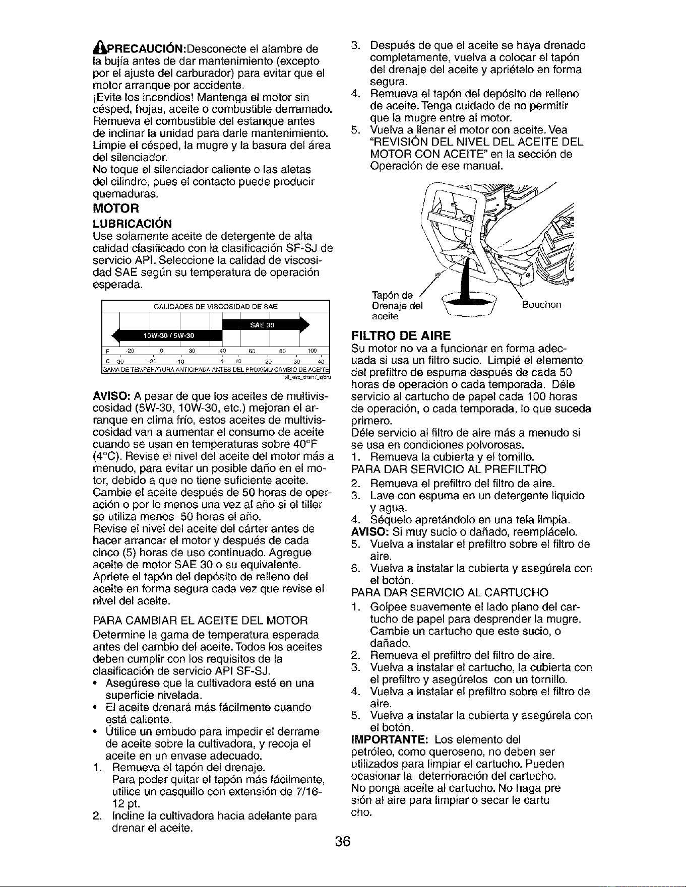
A[_PRECAUCI(_N:Desconecte el alambre de
la bujfa antes de dar mantenimiento (excepto
por el ajuste del carburador) para evitar que el
motor arranque por accidente.
iEvite los incendios! Mantenga el motor sin
c_sped, hojas, aceite o combustible derramado.
Remueva el combustible del estanque antes
de inclinar la unidad para darle mantenimiento.
Limpie el c6sped, la mugre y la basura del Area
del silenciador.
No toque et silenciador caliente o las atetas
del cilindro, pues el contacto puede producir
quemaduras.
MOTOR
LUBRICACION
Use solamente aceite de detergente de alta
calidad clasificado con la clasificaci6n SF-SJ de
servicio API. Seleccione la calidad de viscosi-
dad SAE segt]n su temperatura de operaci6n
esperada.
CALIDADES DE VISCOSIDAD DE SAE
AVISO: A pesar de que los aceites de multivis-
cosidad (5W-30, 10W-30, etc.) mejoran el ar-
ranque en clima frfo, estos aceites de multivis-
cosidad van a aumentar el consumo de aceite
cuando se usan en temperaturas sobre 40°F
(4°C). Revise el nivel del aceite del motor m&s a
menudo, para evitar un posible daSo en el mo-
tor, debido a que no tiene suficiente aceite.
Cambie el aceite despu6s de 50 horas de oper-
aci6n o por Io menos una vez al aSo si el tiller
se utiliza menos 50 horas el aSo.
Revise el nivel del aceite del carter antes de
hacer arrancar el motor y despu_s de cada
cinco (5) horas de uso continuado. Agregue
aceite de motor SAE 30 o su equivalente.
Apriete el tap6n del dep6sito de relleno det
aceite en forma segura cada vez que revise el
nivel del aceite.
PARA CAMBIAR EL ACEITE DEL MOTOR
Determine la gama de temperatura esperada
antes del cambio del aceite. Todos los aceites
{:leben cumplir con los requisitos de la
clasificaci6n de servicio API SF-SJ.
• Aseg_rese que la cultivadora est6 en una
superficie nivelada.
• El aceite drenar& m&s f&cilmente cuando
est#, caliente.
• 0tilice un embudo para impedir el derrame
de aceite sobre la cultivadora, y recoja el
aceite en un envase adecuado.
1. Remueva el tap6n del drenaje.
Para poder quitar el tap6n m&s fAcilmente,
utilice un casquillo con extensi6n de 7/16-
12 pt.
2. Incline la cultivadora hacia adelante para
drenar el aceite.
3. Despu6s de que el aceite se haya drenado
completamente, vuelva a colocar et tap6n
del drenaje del aceite y apri6telo en forma
segura.
4. Remueva el tap6n del dep6sito de relleno
de aceite. Tenga cuidado de no permitir
que la mugre entre al motor.
5. Vuelva a llenar el motor con aceite. Vea
"REVISION DEL NIVEL DEL ACEITE DEL
MOTOR CON ACEITE" en la secci6n de
Operaci6n de ese manual.
Tap6n de
Drenaje del
aceite
Bouchon
FILTRO DE AIRE
Su motor no va a funcionar en forma adec-
uada si usa un filtro sucio. Limpi6 el elemento
del prefiltro de espuma despu6s de cada 50
horas de operaci6n o cada temporada. D_le
servicio al cartucho de papel cada 100 horas
de operaci6n, o cada temporada, 1oque suceda
primero.
D61e servicio al filtro de aire mAs a menudo si
se usa en condiciones polvorosas.
1. Remueva la cubierta y el tornillo.
PARA DAR SERVICIO AL PREFILTRO
2. Remueva el prefiltro del filtro de aire.
3. Lave con espuma en un detergente liquido
y agua.
4. S6quelo apret#,ndolo en una tela timpia.
AMISO: Si muy sucio o dai_ado, reemplAcelo.
5. Vuelva a instalar el prefiltro sobre el filtro de
aire.
6. Vuelva a instatar la cubierta y asegSrela con
el bot6n.
PARA DAR SERVICIO AL CARTUCHO
1. Golpee suavemente el lade piano del car-
tucho de papel para desprender la mugre.
Cambie un cartucho que este sucio, o
daSado.
2. Remueva el prefiltro del filtro de aire.
3. Vuelva a instatar el cartucho, la cubierta con
el prefiltro y asegt]relos con un tornillo.
4. Vuelva a instalar el prefiltro sobre el filtro de
aire.
5. Vuelva a instatar la cubierta y asegSrela con
el bot6n.
IMPORTANTE: Los elemento del
petr61eo, como queroseno, no deben ser
utilizados para limpiar el cartucho. Pueden
ocasionar la deterrioraci6n del cartucho.
No ponga aceite al cartucho. No haga pre
si6n al aire para limpiar o secar le cartu
cho.
36
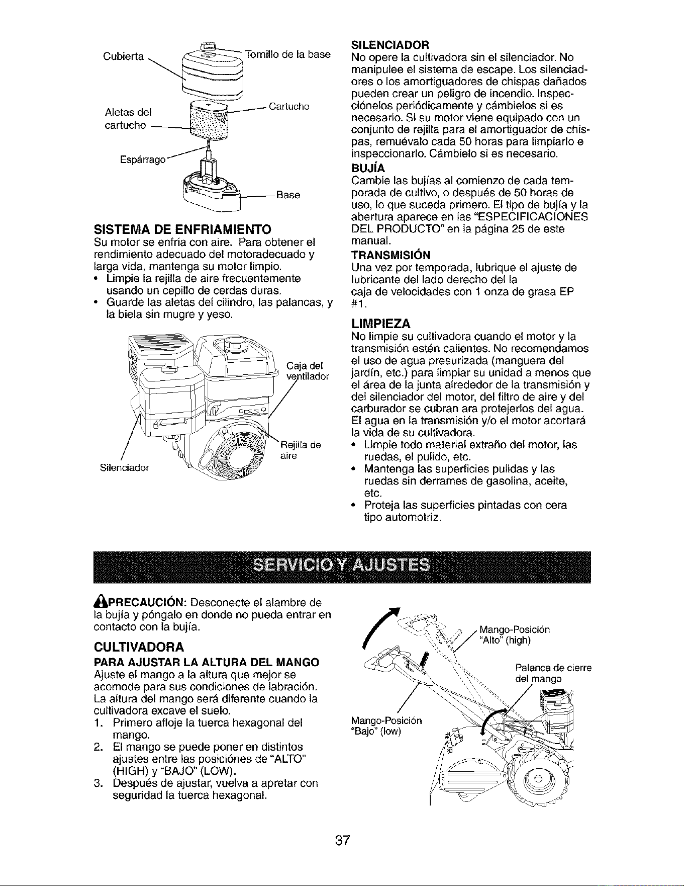
Cubierta _.
Tornillo de la base
Aletas del
SISTEMA DE ENFRIAMIENTO
Su motor se enfria con aire. Para obtener el
rendimiento adecuado del motoradecuado y
larga vida, mantenga su motor limpio.
• Limpie la rejilla de aire frecuentemente
usando un cepillo de cerdas duras.
• Guarde las atetas del cilindro, las palancas, y
la biela sin mugre y yeso.
Silenciador
Caja del
ilia de
aire
SILENCIADOR
No opere la cultivadora sin el silenciador. No
manipulee et sistema de escape. Los silenciad-
ores o los amortiguadores de chispas daSados
pueden crear un peligro de incendio. Inspec-
ci6nelos peri6dicamente y c&mbielos si es
necesario. Si su motor viene equipado con un
conjunto de rejilla para el amortiguador de chis-
pas, remu_vato cada 50 horas para limpiarlo e
inspeccionarlo. C&mbielo si es necesario.
BUJ|A
Cambie las bujfas al comienzo de cada tem-
porada de cultivo, o despu6s de 50 horas de
uso, Io que suceda primero. El tipo de bujfa y la
abertura aparece en las "ESPECIFICACIONES
DEL PRODUCTO" en la p&gina 25 de este
manual.
TRANSMISI(_N
Una vez por temporada, lubrique el ajuste de
lubricante del lado derecho della
caja de velocidades con 1 onza de grasa EP
#1.
LIMPIEZA
No limpie su cultivadora cuando el motor y la
transmisi6n est6n calientes. No recomendamos
el uso de agua presurizada (manguera del
jardfn, etc.) para limpiar su unidad a menos que
el Area de la junta alrededor de la transmisi6n y
del silenciador del motor, del filtro de aire y del
carburador se cubran ara protejerlos del agua.
El agua en la transmisi6n y/o el motor acortar&
la vida de su cultivadora.
• Limpie todo material extraSo del motor, las
ruedas, el pulido, etc.
• Mantenga las superficies pulidas y las
ruedas sin derrames de gasolina, aceite,
etc.
• Proteja las superficies pintadas con cera
tipo automotriz.
,_PRECAUCI(_N: Desconecte el alambre de
la bujia y p6ngalo en donde no pueda entrar en
contacto con la bujfa.
CULTIVADORA
PARA AJUSTAR LA ALTURA DEL MANGO
Ajuste el mango a la altura que mejor se
acomode para sus condiciones de labraci6n.
La attura del mango serA diferente cuando la
cultivadora excave el suelo.
1. Primero afloje la tuerca hexagonal del
mango.
2. El mango se puede poner en distintos
ajustes entre las posici6nes de "ALTO"
(HIGH) y "BAJO" (LOW).
3. Despu6s de ajustar, vuelva a apretar con
seguridad la tuerca hexagonal.
Mango-Posici6n
"Bajo" (low)
"Alto" (high)
Palanca de cierre
del mango
37
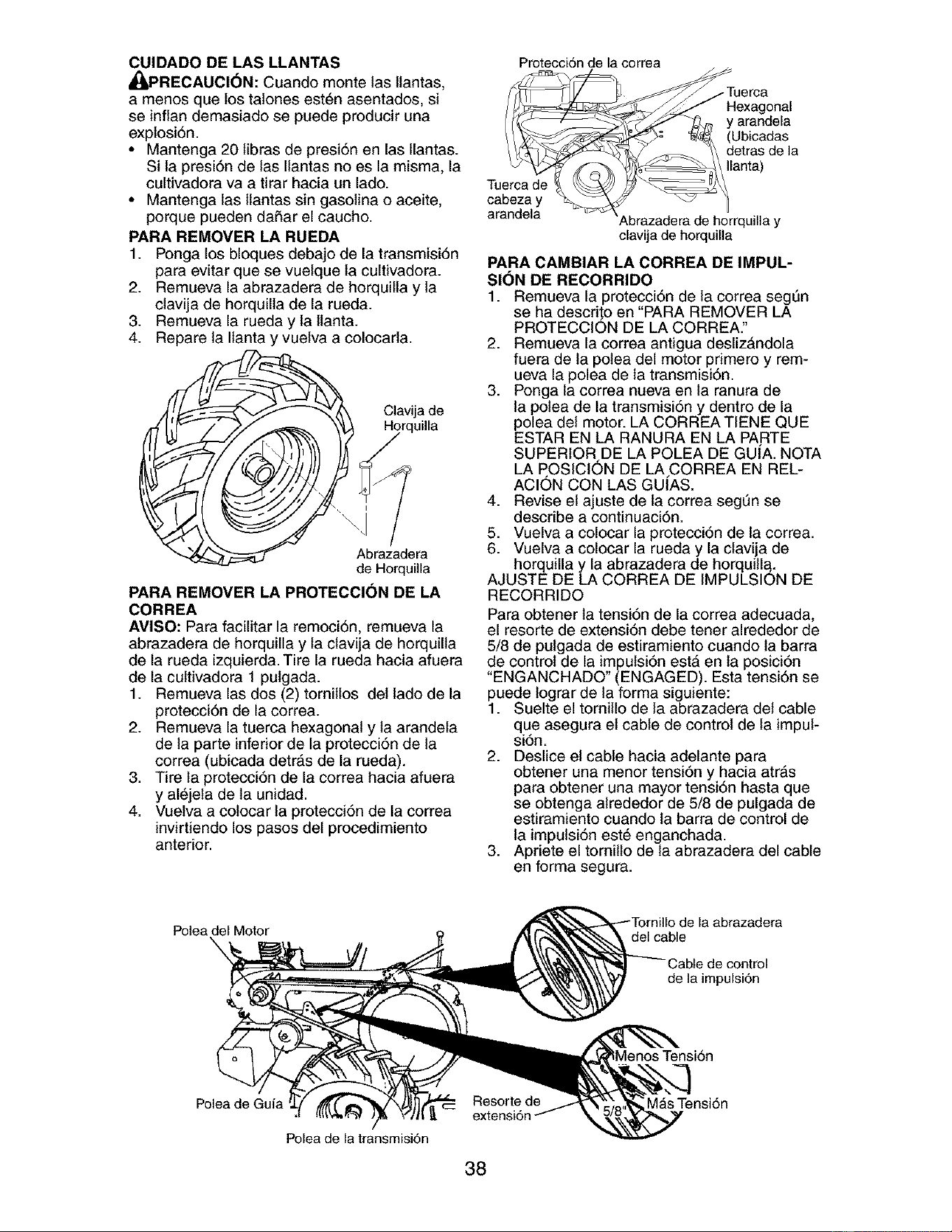
CUIDADO DE LAS LLANTAS
,_PRECAUCI(_N: Cuando monte las llantas,
a menos que los tatones est_n asentados, si
se inflan demasiado se puede producir una
explosi6n.
• Mantenga 20 libras de presi6n en las llantas.
Si la presi6n de las Ilantas no es la misma, la
cultivadora va a tirar hacia un lado.
• Mantenga las llantas sin gasolina o aceite,
porque pueden dafiar el caucho.
PARA REMOVER LA RUEDA
1. Ponga los bloques debajo de la transmisi6n
para evitar que se vuelque la cultivadora.
2. Remueva la abrazadera de horquilla y la
clavija de horquilla de la rueda.
3. Remueva la rueda y la llanta.
4. Repare la Ilanta y vuelva a colocada.
i ! Clavija de
Abrazadera
de Horquilla
PARA REMOVER LA PROTECCI(_N DE LA
CORREA
AVISO: Para facilitar la remoci6n, remueva la
abrazadera de horquilla y la clavija de horquilla
de la rueda izquierda. Tire la rueda hacia afuera
de la cultivadora 1 pulgada.
1. Remueva las dos (2) tornillos del lado de la
protecci6n de la correa.
2. Remueva la tuerca hexagonal y la arandela
de la parte inferior de la protecci6n de la
correa (ubicada detr&s de la rueda).
3. Tire la protecci6n de la correa hacia afuera
y al_jela de la unidad.
4. Vuelva a colocar la protecci6n de la correa
invirtiendo los pasos del procedimiento
anterior.
Protecci6n de la correa
Tuerca de
cabeza y
arandela
--Tuerca
Hexagonal
y arandela
(Ubicadas
detras de la
Ilanta)
clavija de horquilla
PARA CAMBIAR LA CORREA DE IMPUL-
SION DE RECORRIDO
1. Remueva la protecci6n de la correa segSn
se ha descri_o en "PARA REMOVER LA
PROTECClON DE LA CORREA."
2. Remueva la correa antigua desliz&ndola
fuera de la polea del motor primero y rem-
ueva la polea de la transmisi6n.
3. Ponga la correa nueva en la ranura de
la polea de la transmisi6n y dentro de la
polea del motor. LA CORREA TIENE QUE
ESTAR EN LA RANURA EN LA PARTE
SUPERIOR DE LA POLEA DE GU[A. NOTA
LA POSICION DE LA CORREA EN REL-
ACION CON LAS GUIAS.
4. Revise el ajuste de la correa segQn se
describe a continuaci6n.
5. Vuelva a colocar la protecci6n de la correa.
6. Vuelva a colocar la rueda y la clavija de
horquilla y la abrazadera de horquill_.
AJUSTE DE LA CORREA DE IMPULSION DE
RECORRIDO
Para obtener la tensi6n de la correa adecuada,
el resorte de extensi6n debe tener alrededor de
5/8 de pulgada de estiramiento cuando ta barra
de control de la impulsi6n est& en la posici6n
"ENGANCHADO" (ENGAGED). Esta tensi6n se
puede lograr de la forma siguiente:
1. Suelte el tornillo de la abrazadera del cable
que asegura el cable de control de la impul-
si6n.
2. Deslice el cable hacia adelante para
obtener una menor tensi6n y hacia atr&s
para obtener una mayor tensi6n hasta que
se obtenga atrededor de 5/8 de pulgada de
estiramiento cuando la barra de control de
la impulsi6n est6 enganchada.
3. Apriete el tornillo de la abrazadera del cable
en forma segura.
Poleadel Motor
\
la abrazadera
del cable
de la impulsi6n
MenosTensi6n
Polea de Guia
Polea de la transmisi6n
Resorte de M_s Tensi6n
extensi6
38
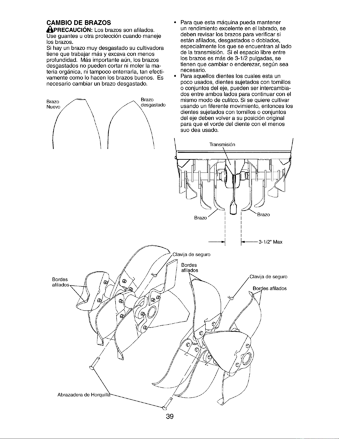
CAMBIO DE BRAZOS °
_PRECAUCI6N: Los brazes son afilados.
Use guantes u otra protecci6n cuando maneje
los brazes.
Si hay un brazo muy desgastado su cultivadora
tiene que trabajar m&s y excava con menos
profundidad. M&s importante at]n, los brazos
desgastados no pueden cortar ni moler la ma-
teria org&nica, ni tampoco enterrarla, tan efecti-
vamente como Io hacen los brazes buenos. Es *
necesario cambiar un brazo desgastado.
Brazo
Brazo
Bordes
Para que esta mAquina pueda mantener
un rendimiento excelente en el labrado, se
deben revisar los brazos para verificar si
est&n afilados, desgastados o doblados,
especialmente los que se encuentran al lado
de la transmisi6n. Si el espacio libre entre
los brazos es m&s de 3-1/2 pulgadas, se
tienen que cambiar o enderezar, segt]n sea
necesario.
Para aquetlos dientes los cuales esta un
poco usados, dientes sujetados con tornilios
o conjuntos del eje, pueden ser intercambia-
dos entre ambos lados para continuar con el
mismo mode de culitco. Si se quiere cultivar
usando un fiferente movimiento, entonces los
dientes sujetados con tornillos o conjuntos
del eje deben voiver a su posici6n original
para que el verde del diente con el menos
sue dea usado.
Bordes
afilados
guro
Clavija de seguro
/
Abrazadera de
39
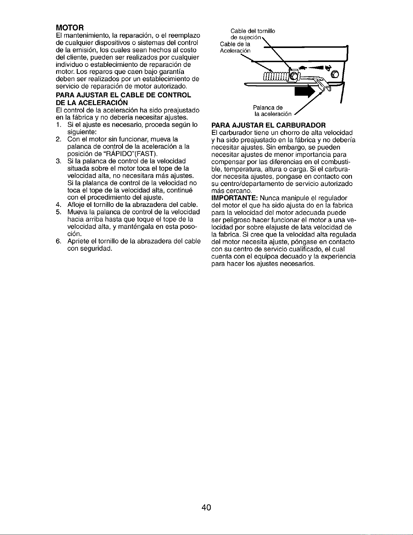
MOTOR
El mantenimiento, la reparaci6n, o el reemplazo
de cualquier dispositivos o sistemas del control
de la emisi6n, los cuates sean hechos al costo
del cliente, pueden ser realizados por cualquier
individuo o establecimiento de reparaci6n de
motor. Los reparos que caen bajo garant[a
deben set realizados por un establecimiento de
servicio de reparaci6n de motor autorizado.
PARA AJUSTAR EL CABLE DE CONTROL
DE LA ACELERACI(_N
El control de la aceleraci6n ha sido preajustado
en la f&brica y no deberfa necesitar ajustes.
1. Si el ajuste es necesario, proceda segSn 1o
siguiente:
2. Con el motor sin funcionar, mueva la
palanca de control de la aceleraci6n a la
posici6n de "RAPIDO'(FAST).
3. Si la palanca de control de la velocidad
situada sobre el motor toca el tope de la
velocidad alta, no necesitara m_s ajustes.
Si la plalanca de control de la velocidad no
toca el tope de la velocidad alta, continu6
con el procedimiento del ajuste.
4. Afloje el tornillo de la abrazadera del cable.
5. Mueva la palanca de control de la velocidad
hacia ardba hasta que toque el tope de la
velocidad alta, y mant6ngata en esta poso-
ci6n.
6. Apriete el tornillo de la abrazadera del cable
con seguridad.
Cable del tornillo
de sujeci6n\
Cable de la
Acelera_,_ _ ]
PARA AJUSTAR EL CARBURADOR
El carburador tiene un chorro de alta velocidad
y ha sido preajustado en ta f&brica y no deber[a
necesitar ajustes. Sin embargo, se pueden
necesitar ajustes de menor importancia para
compensar por las diferencias en el combusti-
ble, temperatura, altura o carga. Si el carbura-
dor necesita ajustes, pongase en contacto con
su centro/departamento de servicio autorizado
m&s cercano.
IMPORTANTE: Nunca manipule el regulador
det motor el que ha sido ajusta do en ta fabrica
para la velocidad del motor adecuada puede
ser peligroso hacer funcionar el motor a una ve-
Iocidad por sobre elajuste de lata velocidad de
la fabrica. Si cree que la velocidad alta regulada
det motor necesita ajuste, p6ngase en contacto
con su centro de servicio cualificado, el cual
cuenta con el equipoa decuado y la experiencia
para hacer los ajustes necesarios.
40
Inmediatamente prepare su cultivadora para el
atmacenamiento al final de la temporada o si la
unidad no se va a usar per 30 dias o m&s.
_ADVERTENClA: Nunca almacene la culti-
vadora con gasolina en el estanque dentro de
un edificio en donde los gases pueden alcanzar
una llama expuesta o una chispa. Permita que
el motor se enfrie antes de almacenarlo en
cualquier recinto privado.
CULTIVADORA
1. Limpie toda ta cultivadora (yea "LIMPIEZA"
en ta secci6n de Mantenimiento en este
manual).
2. Inspeccione y cambie las correas, si es
necesario (vea las instrucciones para et
cambio de la correa en la secci6n de Servi-
cioy Ajustes de este manual).
3. Lubriquela segSn se muestra en ta secci6n
de Mantenimiento en este manual.
4. AsegSrese que todas las tuercas, pernos y
tornillos est6n apretados en forma segura.
Inspeccione las partes movibles para verifi-
car si est&n dai_adas, rotas o desgastadas.
C&mbielas si es necesario.
5. Retoque todas las superficies pintadas
que est_n oxidadas o picadas; use una lija
suavemente antes de pintar.
MOTOR
SISTEMA DE COMBUSTIBLE
IMPORTANTE: Es importante evitar que se
formen dep6sitos de goma en partes funda-
mentales del sistema de combustible tales
como el carburador, et filtro del combustible,
la manguera del combustible o en el estanque
durante et almacenamiento. La experiencia
tambi6n indica que los combustibles mezclados
con alcohol (conocido como gasohol o que
tienen etanol o metanol) pueden atraer hume-
dad, lo que conduce a la separaci6n de &cidos
durante el almacenamiento. La gasolina &cidica
puede daSar el sistema de combustible de un
motor durante el periodo de almacenamiento.
1. Drene el estanque de combustible.
2. Haga arrancar el motor y d_jelo funcionar
hasta que las t[neas del combustible y el
carburador est_n vac[os.
• Nunca use los productos para limpieza del
carburador odel motor en el estanque de
combustible pues se pueden producir daiSos
permanentes.
• Use combustible nuevo la pr6xima tempo-
rada.
AVISO: El estabilizador de combustible es una
altemativa aceptable para reducir a un minimo
la formaci6n de dep6sitos de goma en et com-
bustible durante el perbdo de almacenamiento.
Agregue estabilizador a la gasolina en el
estanque de combustible o en el envase para
el almacenamiento. Siempre siga la proporci6n
de mezcla que se encuentra en el envase
del estabilizador. Haga funcionar el motor por
Io menos 10 minutos despu6s de agregar el
estabilizador, para permitir que _ste llegue al
carburador. No drene la gasolina del estanque
de gasolina y el carburador si se est& usando
estabilizador de combustible.
ACEITE DEL MOTOR
Drene el aceite (con el motor caliente) y
c_,mbielo con aceite de motor limpio. (Vea "MO-
TOR" en la secci6n de Mantenimiento de este
manual.)
CILINDRO(S)
1. Remueva la bujfa.
2. Vacie una onza de aceite a trav6s del agu-
jero de la buj[a en el cilindro.
3. Tire et mango det arrancador, lentamente,
varias veces para distribuir el aceite.
4. Cambie por una bujia nueva.
OTROS
• No guarde la gasolina de una temporada a la
otra.
• Cambie el envase de la gasolina si se emp-
ieza a oxidar. La oxidaci6n y/o la mugre en
su gasolina producir&n problemas.
• Si es posible, guarde su unidad en un recinto
cerrado y c_brala para protegerla contra el
polvo y la mugre.
• Cubra su unidad con un forro protector
adecuado que no retenga la humedad. No
use pl_,stico. El pl_,stico no puede respirar, Io
que permite la formaci6n de condensaci6n,
lo que producir#, la oxidaci6n de su unidad.
IMPORTANTE: Nunca cubra la cultivadora
mientras el motor y las areas de escape toda-
via estan calientes.
41
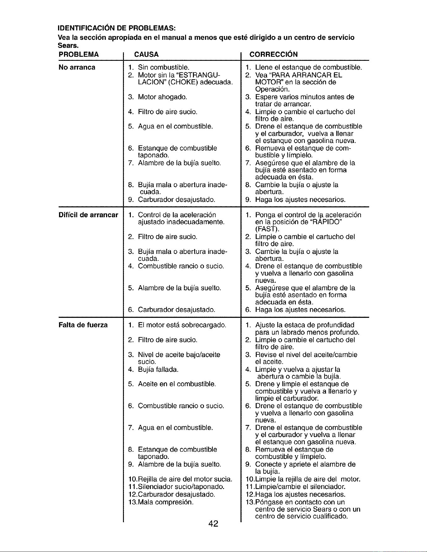
IDENTIFICACI(_N DE PROBLEMAS:
Vea la seccibn apropiada en el manual a menos que estd dirigido a un centro de servicio
Sears.
PROBLEMA CORRECCI()N
No arranca
Dificil de arrancar
Falta de fuerza
CAUSA
1. Sin combustible.
2. Motor sin la"ESTRANGU-
LACION" (CHOKE) adecuada.
3. Motor ahogado.
4. Filtro de aire sucio.
5. Agua en el combustible.
6. Estanque de combustible
taponado.
7. Alambre de la bujfa suelto.
8. Buj[a mata o abertura inade-
cuada.
9. Carburador desajustado.
1. Control de la aceleraci6n
ajustado inadecuadamente.
2. Filtro de aire sucio.
3. Buj[a mata o abertura inade-
cuada.
4. Combustible rancio o sucio.
5. Alambre de la bujfa suelto.
6. Carburador desajustado.
1. El motor estA sobrecargado.
2. Filtro de aire sucio.
3. Nivel de aceite bajo/aceite
sucio.
4. Bujfa fallada.
5. Aceite en el combustible.
6. Combustible rancio o sucio.
7. Agua en el combustible.
8. Estanque de combustible
taponado.
9. Alambre de la bujfa suelto.
10. Rejilla de aire del motor sucia.
11.Silenciador sucio/taponado.
12.Carburador desajustado.
13.Mala compresi6n.
42
1. Llene el estanque de combustible.
2. Vea "PARA ARRANCAR EL
MOTOR" en la secci6n de
Operaci6n.
3. Espere varies minutos antes de
tratar de arrancar.
4. Limpie o cambie el cartucho del
filtro de aire.
5. Drene el estanque de combustible
y el carburador, vuelva a llenar
el estanque con gasolina nueva.
6. Remueva el estanque de com-
bustible y Iimpielo.
7. Aseg_rese que et alambre de la
bujia est_ asentado en forma
adecuada en _sta.
8. Cambie la bujfa o ajuste la
abertura.
9. Haga los ajustes necesarios.
1. Ponga el control de 1_aceleraci6n
en la posici6n de "RAPIDO"
(FAST).
2. Limpie o cambie el cartucho del
filtro de aire.
3. Cambie la buj[a o ajuste la
abertura.
4. Drene el estanque de combustible
y vuelva a llenarlo con gasolina
nueva.
5. Aseg_rese que et alambre de la
bujia est6 asentado en forma
adecuada en _sta.
6. Haga los ajustes necesarios.
1. Ajuste la estaca de profundidad
para un labrado menos profundo.
2. Limpie o cambie el cartucho del
filtro de aire.
3. Revise el nivel del aceite/cambie
el aceite.
4. Limpie y vuelva a ajustar la
abertura o cambie la bujia.
5. Drene y limpie el estanque de
combustible y vuelva a llenarlo y
limpie el carburador.
6. Drene el estanque de combustible
y vuelva a llenarlo con gasolina
nueva.
7. Drene el estanque de combustible
y el carburador y vuelva a Ilenar
el estanque con gasolina nueva.
8. Remueva el estanque de
combustible y limpielo.
9. Conecte y apriete el alambre de
la bujia.
10.Limpie la rejilla de aire del motor.
11.Limpie/cambie el silenciador.
12.Haga los ajustes necesarios.
13.P6ngase en contacto con un
centro de servicio Sears o con un
centro de servicio cualificado.
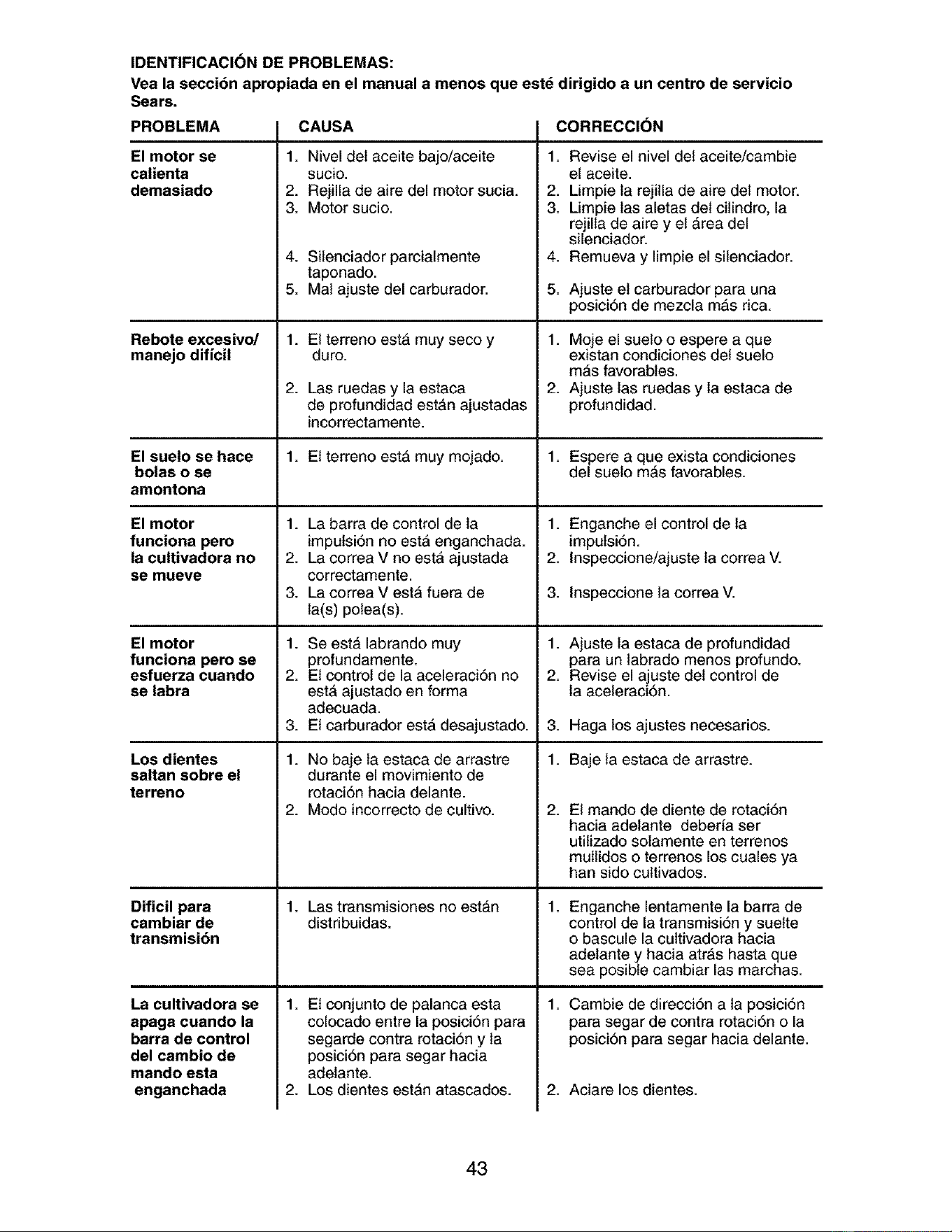
IDENTIFICACION DE PROBLEMAS:
Vea la seccibn apropiada en el manual a menos que estd dirigido a un centro de servicio
Sears.
PROBLEMA CAUSA CORRECClON
El motor se
calienta
demasiado
Rebote excesivo/
manejo diffcil
El suelo se hace
bolas o se
amontona
El motor
funciona pero
la cultivadora no
se mueve
El motor
funciona pero se
esfuerza cuando
se labra
Los dientes
saltan sobre el
terreno
Dificil para
cambiar de
transmisibn
La cultivadora se
apaga cuando la
barra de control
del cambio de
mando esta
enganchada
1. Nivel del aceite bajo/aceite
sucio.
2. Rejilla de aire del motor sucia.
3. Motor sucio.
4. Silenciador parcialmente
taponado.
5. Mat ajuste del carburador.
1. El terreno estA muy seco y
duro.
2. Las ruedas y la estaca
de profundidad estAn ajustadas
incorrectamente.
1. El terreno estA muy mojado.
1. La barra de control de la
impulsi6n no estA enganchada.
2. La correa V no estA ajustada
correctamente.
3. La correa V esta fuera de
la(s) polea(s).
1. Se estA labrando muy
profundamente.
2. El control de la aceleraci6n no
estA ajustado en forma
adecuada.
3. El carburador esta desajustado.
1. No baje la estaca de arrastre
durante el movimiento de
rotaci6n hacia delante.
2. Modo incorrecto de cultivo.
1. Las transmisiones no estAn
distribuidas.
1. El conjunto de palanca esta
colocado entre la posici6n para
segarde contra rotaci6n y la
posici6n para segar hacia
adetante.
2. Los dientes estan atascados.
1. Revise el nivel del aceite/cambie
el aceite.
2. Limpie la rejilla de aire del motor.
3. Limpie las aletas del cilindro, la
rejilla de aire y el Area del
silenciador.
4. Remueva y limpie el silenciador.
.
1.
2.
1.
1.
2.
3.
Ajuste el carburador para una
posici6n de mezcla mas rica.
Moje el suelo o espere a que
existan condiciones del suelo
mAs favorables.
Ajuste las ruedas y la estaca de
profundidad.
Espere a que exista condiciones
del suelo mAs favorables.
Enganche el control de la
impulsi6n.
Inspeccione/ajuste la correa V.
Inspeccione la correa V.
1. Ajuste la estaca de profundidad
para un labrado menos profundo.
2. Revise el ajuste del control de
la aceleraci6n.
.
1.
2.
1.
1.
Haga los ajustes necesarios.
Baje la estaca de arrastre.
El mando de diente de rotaci6n
hacia adelante deberfa ser
utilizado solamente en terrenos
mullidos o terrenos los cuales ya
han side cultivados.
Enganche lentamente la barra de
control de la transmisi6n y suelte
o bascule la cultivadora hacia
adelante y hacia atras hasta que
sea posible cambiar las marchas.
Cambie de direcci6n a ta posici6n
para segar de contra rotaci6n o la
posici6n para segar hacia delante.
2. Aciare los dientes.
43
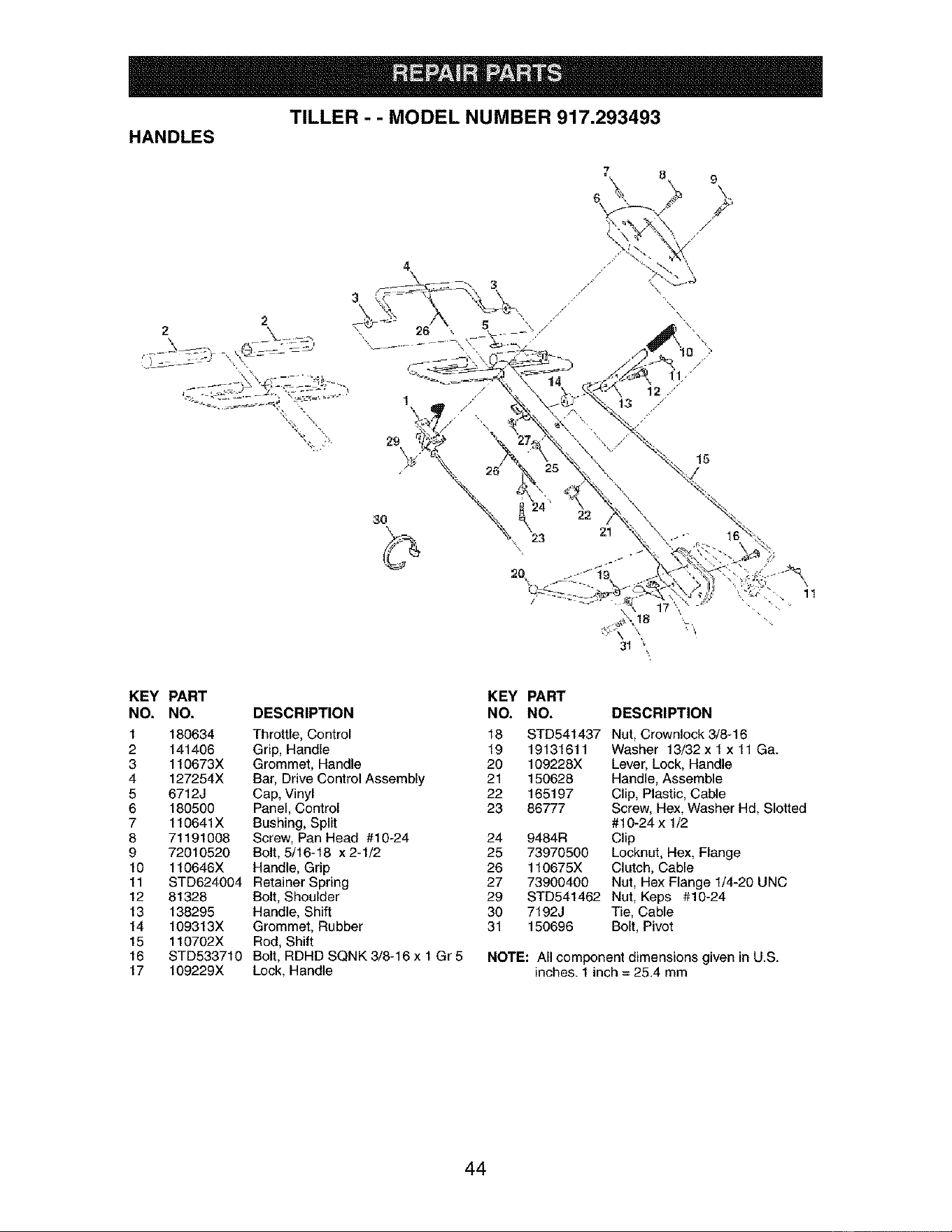
TILLER - - MODEL NUMBER 917.293493
HANDLES
2
23
/
15
KEY PART
NO. NO.
1 180634
2 141406
3 110673X
4 127254X
5 6712J
6 180500
7 110641X
8 71191008
9 72010520
10 110646X
11 STD624004
12 81328
13 138295
14 109313X
15 110702X
16 STD533710
17 109229X
KEY
DESCRIPTION NO.
Throttle, Control 18
Grip, Handle 19
Grommet, Handle 20
Bar, Drive Control Assembly 21
Cap, Vinyl 22
Panel, Control 23
Bushing, Split
Screw, Pan Head #10-24 24
Bolt, 5/16-18 x 2-1/2 25
Handle, Grip 26
Retainer Spring 27
Bolt, Shoulder 29
Handle, Shift 30
Grommet, Rubber 31
Rod, Shift
Bolt, RDHD SQNK 3/8-16 x 1 Gr 5
Lock, Handle
PART
NO. DESCRIPTION
STD541437 Nut, Crownlock 3/8-16
19131611 Washer 13/32 x 1 x 11 Ga.
109228X Lever, Lock, Handle
150628 Handle, Assemble
165197 Clip, Plastic, Cable
86777 Screw, Hex, Washer Hd, Slotted
#10-24xl/2
9484R Clip
73970500 Locknut, Hex, Flange
110675X Clutch, Cable
73900400 Nut, Hex Flange 1/4-20 UNC
STD541462 Nut, Keps #10-24
7192J Tie, Cable
150696 Bolt, Pivot
NOTE: All component dimensions given in U.S.
inches. 1 inch = 25.4 mm
44
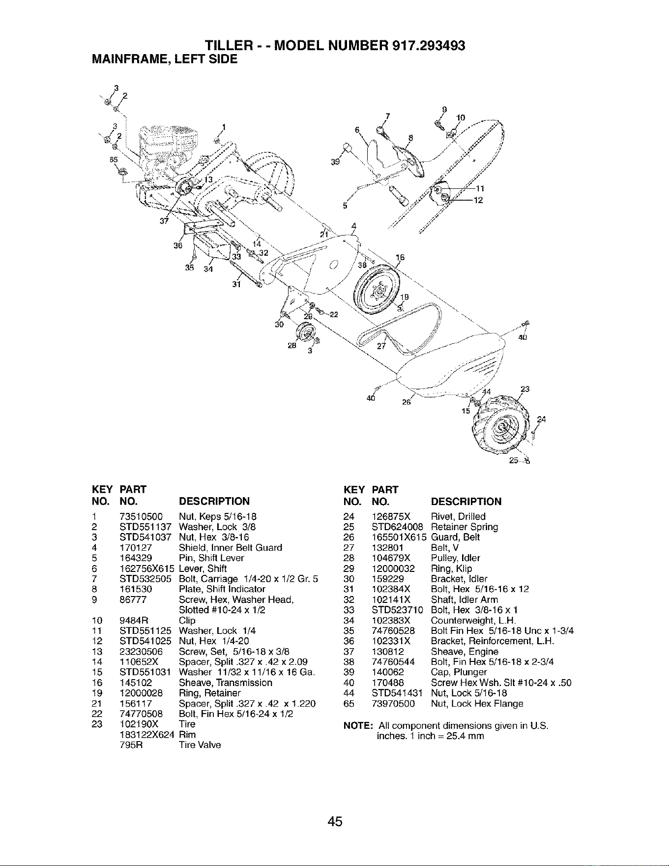
TILLER - - MODEL NUMBER 917.293493
MAINFRAME, LEFT SIDE
37
31
3O
28
3
/
5
4O
!1
15
23
2.4
KEY PART
NO. NO. DESCRIPTION
1
2
3
4
5
6
7
8
9
10
11
12
13
14
15
16
19
21
22
23
73510500 Nut, Keps 5/16-18
STD551137 Washer, Lock 3/8
STD541037 Nut, Hex 3/8-16
170127 Shield, Inner Belt Guard
164329 Pin, Shift Lever
162756X615 Lever, Shift
STD532505 Bolt, Carriage 1/4-20 x 1/2 Gr. 5
161530
86777
9484R
STD551125
STD541025
2323O5O6
110652X
STD551031
145102
12000028
156117
74770508
102190X
183122X624
Plate, Shift Indicator
Screw, Hex, Washer Head,
Slotted #10-24 x 1/2
Clip
Washer, Lock 1/4
Nut, Hex 1/4-20
Screw, Set, 5/16-18 x 3/8
Spacer, Split .327 x .42 x 2.09
Washer 11/32 x 11/16 x 16 Ga.
Sheave, Transmission
Ring, Retainer
Spacer, Split .327 x .42 x 1.220
Bolt, Fin Hex 5/16-24 x 1/2
Tire
Rim
795R Tire Valve
KEY
NO.
24
25
26
27
28
29
30
31
32
33
34
35
36
37
38
39
40
44
65
PART
NO. DESCRIPTION
126875X Rivet, Drilled
STD624008 Retainer Spring
165501X615 Guard, Belt
132801 Belt, V
104679X Pulley, Idler
12000032 Ring, Klip
159229 Bracket, Idler
102384X Bolt, Hex 5/16-16 x 12
102141X Shaft, Idler Arm
STD523710 Bolt, Hex 3/8-16 x 1
102383X
74760528
102331X
130812
74760544
140062
170488
STD541431
73970500
Counterweight, L.H.
Bolt Fin Hex 5/16-18 Unc x 1-3/4
Bracket, Reinforcement, L.H.
Sheave, Engine
Bolt, Fin Hex 5/16-18 x 2-3/4
Cap, Plunger
Screw Hex Wsh. Sit #10-24 x .50
Nut, Lock 5/16-18
Nut, Lock Hex Flange
NOTE: All component dimensions given in U.S.
inches. 1 inch = 25.4 mm
45
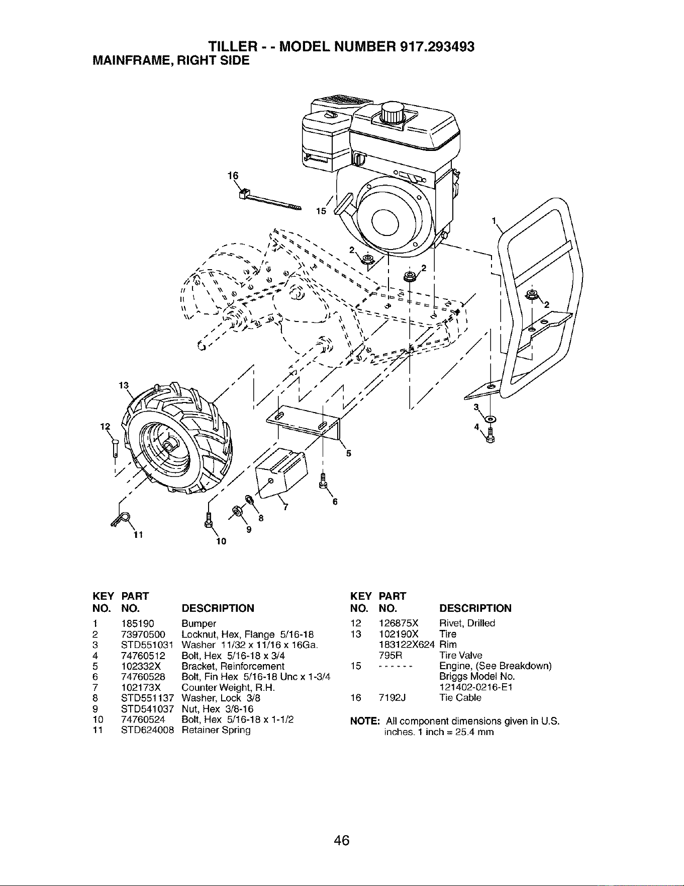
TILLER - - MODEL NUMBER 917.293493
MAINFRAME, RIGHT SIDE
16
13
12
,/
11
8
9
10
5
6
4\
KEY PART
NO. NO.
1 185190
2 73970500
3 STD551031
4 74760512
5 102332X
6 74760528
7 102173X
8 STD551137
9 STD541037
10 74760524
11 STD624008
DESCRIPTION
Bumper
Locknut, Hex, Flange 5/16-18
Washer 11/32 x 11/16 x 16Ga.
Bolt, Hex 5/16-18 x 3/4
Bracket, Reinforcement
Bolt, Fin Hex 5/16-18 Uncx 1-3/4
Counter Weight, R.H.
Washer, Lock 3/8
Nut, Hex 3/8-16
Bolt, Hex 5/16-18 x 1-1/2
Retainer Spring
KEY PART
NO. NO. DESCRIPTION
12 126875X Rivet, Drilled
13 102190X Tire
183122X624 Rim
795R Tire Valve
15 Engine, (See Breakdown)
Briggs Model No.
121402-0216-E1
16 7192J Tie Cable
NOTE: All component dimensions given in U.S.
inches. 1 inch = 25.4 mm
46
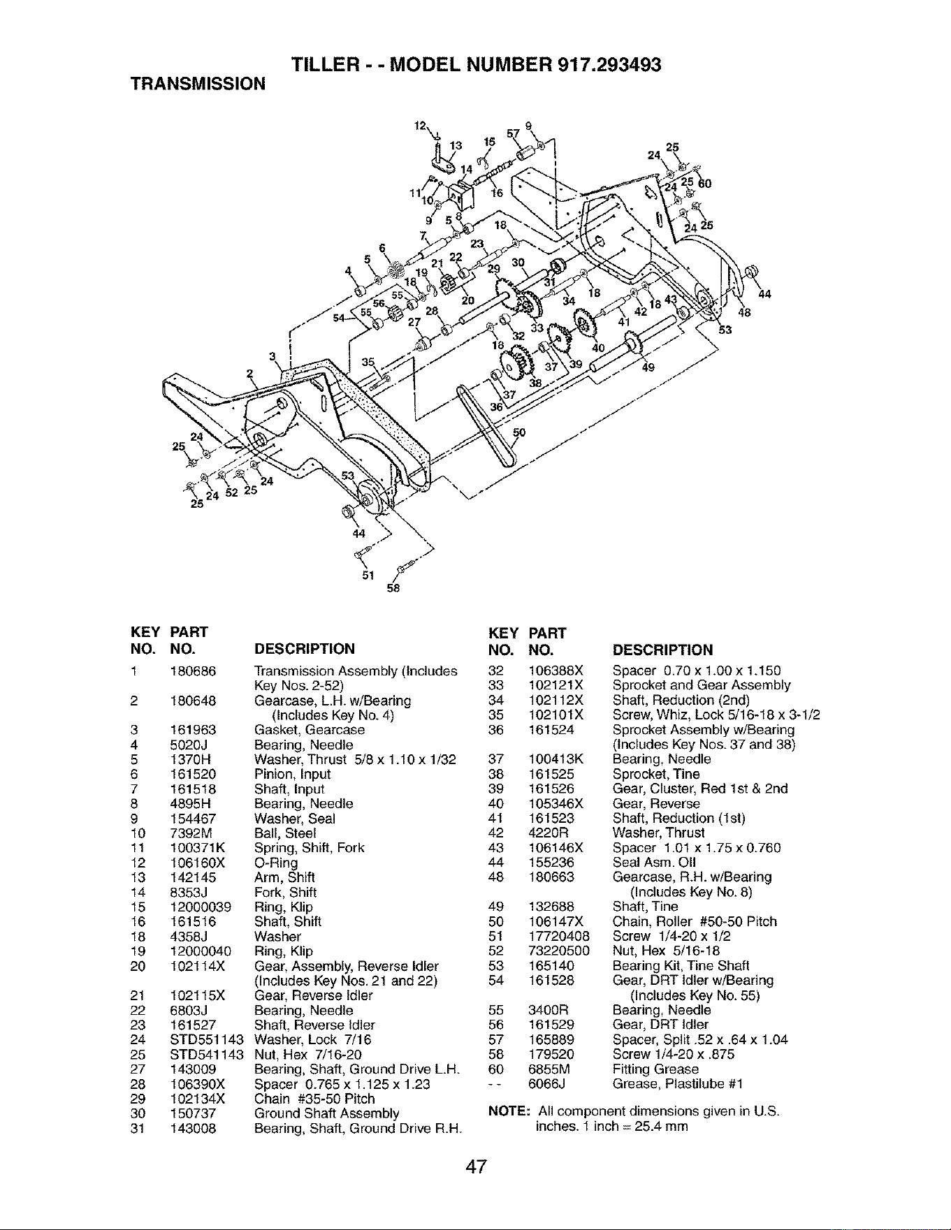
TILLER - - MODEL NUMBER 917.293493
TRANSMISSION
11
24
25
44
51
58
53
48
KEY PART
NO. NO.
1 180686
2 180648
3 161963
4 5O2OJ
5 1370H
6 161520
7 161518
8 4895H
9 154467
10 7392M
11 100371K
12 106160X
13 142145
14 8353J
15 12000039
16 161516
18 4358J
19 12000040
20 102114X
21 102115X
22 6803J
23 161527
24 STD551143
25 STD541143
27 143009
28 106390X
29 102134X
30 150737
31 143008
DESCRIPTION
KEY PART
NO. NO.
Transmission Assembly (Includes 32 106388X
Key Nos. 2-52) 33 102121X
Gearcase, L.H. w/Bearing 34 102112X
(Includes Key No. 4) 35 102101X
Gasket, Gearcase 36 161524
Bearing, Needle
Washer, Thrust 5/8 x 1.10 x 1/32 37 100413K
Pinion, Input 38 161525
Shaft, Input 39 161526
Bearing, Needle 40 105346X
Washer, Seal 41 161523
Ball, Steel 42 4220R
Spring, Shift, Fork 43 106146X
O-Ring 44 155236
Arm, Shift 48 180663
Fork, Shift
Ring, Klip 49 132688
Shaft, Shift 50 106147X
Washer 51 17720408
Ring, Klip 52 73220500
Gear, Assembly, Reverse Idler 53 165140
(Includes Key Nos. 21 and 22) 54 161528
Gear, Reverse Idler
Bearing, Needle 55 3400R
Shaft, Reverse Idler 56 161529
Washer, Lock 7/16 57 165889
Nut, Hex 7/16-20 58 179520
Bearing, Shaft, Ground Drive L.H. 60 6855M
Spacer 0.765 x 1.125 x 1.23 - - 6066J
Chain #35-50 Pitch
Ground Shaft Assembly
Bearing, Shaft, Ground Drive R.H.
DESCRIPTION
Spacer 0.70x 1.OOx 1.150
Sprocket and Gear Assembly
Shaft, Reduction (2nd)
Screw, Whiz, Lock 5/16-18 x 3-1/2
Sprocket Assembly w/Bearing
(Includes Key Nos. 37 and 38)
Bearing, Needle
Sprocket, Tine
Gear, Cluster, Red 1st & 2nd
Gear, Reverse
Shaft, Reduction (1st)
Washer, Thrust
Spacer 1.01 x 1.75 x 0.760
Seal Asm. OII
Gearcase, R.H. w/Bearing
(Includes Key No. 8)
Shaft, Tine
Chain, Roller #50-50 Pitch
Screw 1/4-20 x 1/2
Nut, Hex 5/16-18
Bearing Kit, Tine Shaft
Gear, DRT Idler w/Bearing
(Includes Key No. 55)
Bearing, Needle
Gear, DRT Idler
Spacer, Split .52 x .64 x 1.04
Screw 1/4-20 x .875
Fitting Grease
Grease, Plastilube #1
NOTE: All component dimensions given in U.S.
inches. 1 inch = 25.4 mm
47
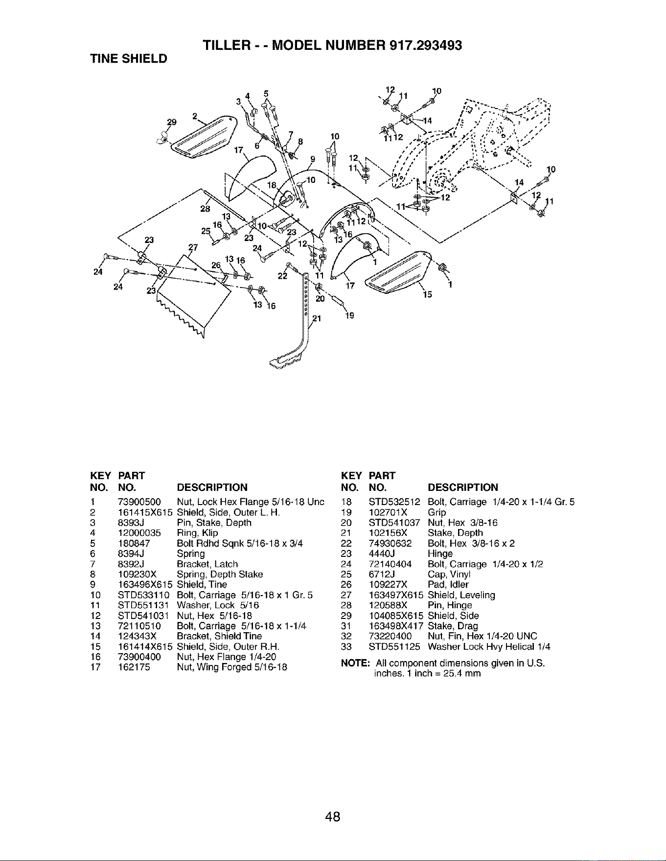
TILLER - - MODEL NUMBER 917.293493
TINE SHIELD
29
10
12
24
24 17
21 19
15
KEY PART
NO. NO.
1 73900500
2 161415X615
3 8393J
4 12000035
5 180847
6 8394J
7 8392J
8 109230X
9 163496X615
10 STD533110
11 STD551131
12 STD541031
13 72110510
14 124343X
15 161414X615
16 73900400
17 162175
DESCRIPTION
Nut, Lock Hex Flange 5/16-16 Unc
Shield, Side, Outer L. H.
Pin, Stake, Depth
Ring, Klip
Bolt Rdhd Sqnk 5/16-18 x 3/4
Spring
Bracket, Latch
Spring, Depth Stake
Shield, Tine
Bolt, Carriage 5/16-18 x 1 Gr. 5
Washer, Lock 5/16
Nut, Hex 5/16-18
Bolt, Carriage 5/16-18x 1-1/4
Bracket, Shield Tine
Shield, Side, Outer R.H.
Nut, Hex Flange 1/4-20
Nut, Wing Forged 5/16-18
KEY PART
NO. NO. DESCRIPTION
18 STD532512 Belt, Carriage 1/4-20 x 1-1/4 Gr. 5
19 102701X Grip
20 STD541037 Nut, Hex 3/8-16
21 102156X Stake, Depth
22 74930632 Bolt, Hex 3/8-16 x 2
23 4440J Hinge
24 72140404 Bolt, Carriage 1/4-20 x 1/2
25 6712J Cap, Vinyl
26 109227X Pad, Idler
27 163497X615 Shield, Leveling
28 120588X Pin, Hinge
29 104085X615 Shield, Side
31 163498X417 Stake, Drag
32 73220400 Nut, Fin, Hex 1/4-20 UNC
33 STD551125 Washer Lock Hvy Helical 1/4
NOTE: All component dimensions given in U.S.
inches. 1 inch = 25.4 mm
48
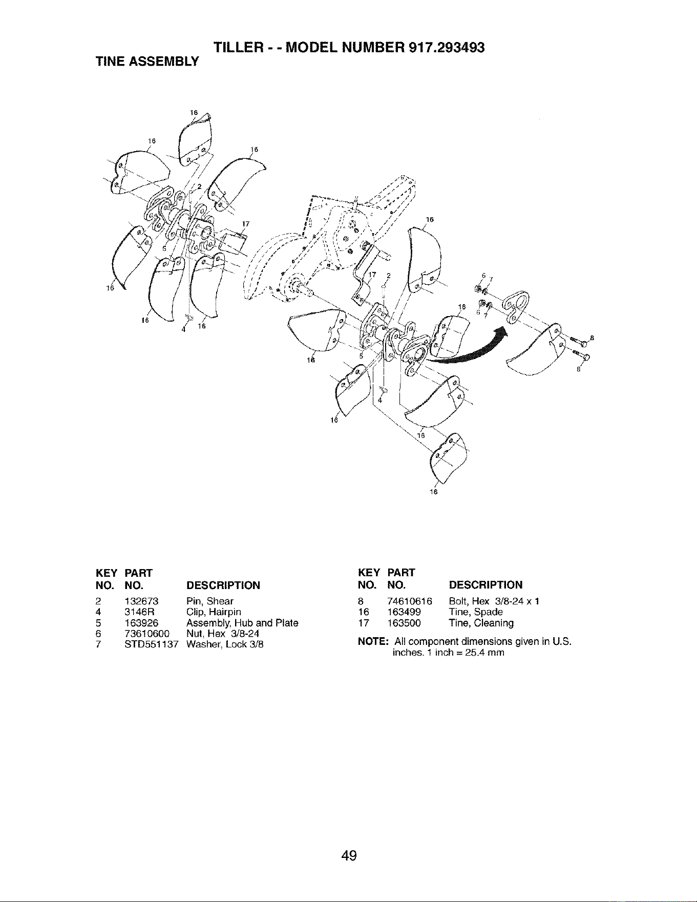
TILLER - - MODEL NUMBER 917.293493
TINE ASSEMBLY
16
16
4_ 16
16
\
8
8
KEY PART
NO. NO. DESCRIPTION
2
4
5
6
7
132673 Pin, Shear
3146R Clip, Hairpin
163926 Assembly, Hub and Plate
73610600 Nut, Hex 3/8-24
STD551137 Washer, Lock 3/8
KEY PART
NO. NO. DESCRIPTION
8 74610616 Bolt, Hex 3/8-24 x 1
16 163499 Tine, Spade
17 163500 Tine, Cleaning
NOTE: All component dimensions given in U.S.
inches. 1 inch = 25.4 mm
49
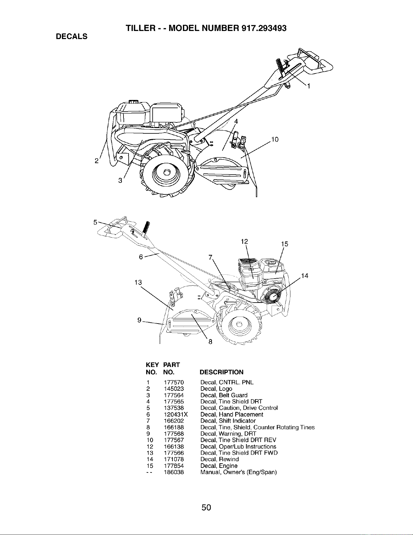
TILLER - - MODEL NUMBER 917.293493
DECALS
12 15
13
8
KEY
NO.
1
2
3
4
5
6
7
8
9
10
12
13
14
15
PART
NO.
177570
145023
177564
177565
137538
120431X
166202
166188
177568
177567
166138
177566
171078
177854
186038
DESCRIPTION
Decal, CNTRL. PNL
Decal, Logo
Decal, Belt Guard
Decal, Tine Shield DRT
Decal, Caution, Drive Control
Decal, Hand Placement
Decal, Shift Indicator
Decal, Tine, Shield, Counter Rotating Tines
Decal, Warning, DRT
Decal, Tine Shield DRT REV
Decal, Oper/Lub Instructions
Decal, Tine Shield DRT FWD
Decal, Rewind
Decal, Engine
Manual, Owner's (Eng/Span)
50
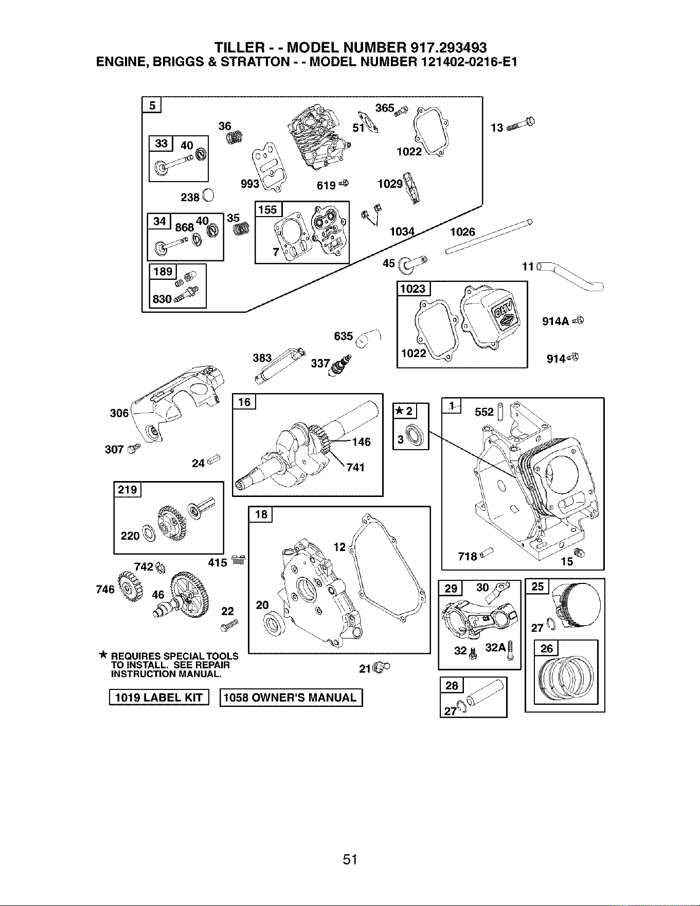
TILLER - - MODEL NUMBER 917.293493
ENGINE, BRIGGS & STRATTON - - MODEL NUMBER 121402-0216-E1
238
830
REQUIRES SPECIAL TOOLS
TO INSTALL. SEE REPAIR
INSTRUCTION MANUAL.
I 1019 LABEL KIT I 11058 OWNER'S MANUAL I
718 _
32 _ 32A_
51
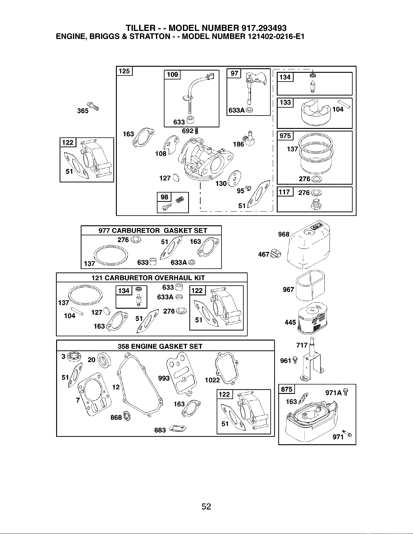
TILLER - - MODEL NUMBER 917.293493
ENGINE, BRIGGS & STRATTON - - MODEL NUMBER 121402-0216-E1
365_
633
692
127
51
137_
276_
__J276_
977 CARBURETOR GASKET SET
276
13; 633_ 633A_
121 CARBURETOR OVERHAUL KIT
6a3@
633A
127 _ 276
163_
358 ENGINE GASKET SET
868_
883_
961_
_75J _ 971A_
52

TILLER - - MODEL NUMBER 917.293493
ENGINE, BRIGGS & STRATTON - - MODEL NUMBER 121402-0216-E1
209A
188_
_6_ 615_
18_1N
281
334_
958
19o_
851
836A_
676
836_
883
53
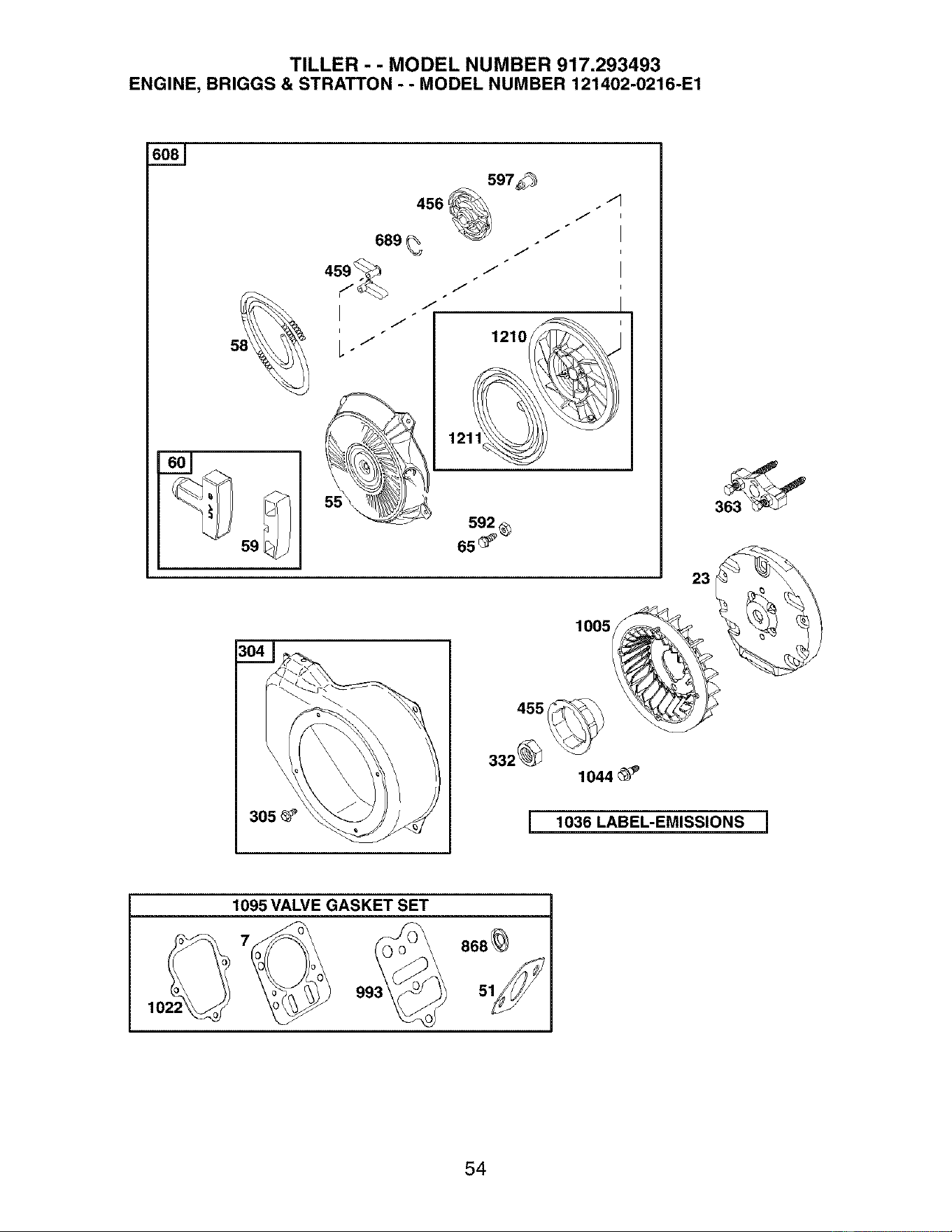
TILLER - - MODEL NUMBER 917.293493
ENGINE, BRIGGS & STRATTON - - MODEL NUMBER 121402-0216-E1
597_
456 .4
689
459 ._
7"
L _j
J
J
J
J
J
1210_
12111_
592
65 _
23
1005
1044_ P
[ 1036 LABEL-EMISSIONS J
1095VALVE GASKET SET
1022_ 993_ 868_
54

TILLER - - MODEL NUMBER 917.293493
ENGINE, BRIGGS & STRATTON - - MODEL NUMBER 121402-0216-E1
KEY PART KEY PART
NO. NO. DESCRIPTION NO. NO. DESCRIPTION
1 690045 Cylinder Assembly 98 398185 Kit-Idle Speed
2 399269 Kit-Bushing/Seal 104 691242 Q Pin-Float Hinge
3 299819 • Seal-Oil (Magneto Side) 108 691182 Plate-Choke
5 693643 Head-Cylinder 109 693628 Shaft-Choke
7 695166 °+ Gasket-CylinderHead 117 690048 Jet-Main
11 693647 Tube-Breather 121 695157 Kit-Carburetor Overhaul
12 692549 • Gasket-Crankcase 122 693749 °Q Spacer-Carburetor
13 691137 Screw (Cylinder Head) 125 693518 Carburetor
15 691686 Plug-Oil Drain 127 691739 _ Plug-Welch
16 693887 Crankshaft 130 691181 Valve-Throttle
18 694466 Cover-Crankcase 133 398187 Float-Carburetor
20 692550 • Seal-Oil (PTO Side) 134 398188 Q Valve-Needle/Seat
21 281658 Cap-Oil Fill 137 693981 Q:I: Gasket-Float Bowl
22 692551 Screw (Crankcase Cover) 146 690979 Key-Timing
23 692987 Flywheel 155 695168 Plate-Cylinder Head
24 222698 Key-Flywheel 163 693458 "Q:I: Gasket-Air Cleaner
25 499627 Piston Assembly (Standard) 186 692317 Connector-Hose
692788 Piston Assembly (.010" O.S.) 187 691050 Line-Fuel (Cut to Required
692789 Piston Assembly (.020" O.S.) Length)
692790 Piston Assembly (.030 O.S.) 187A 692601 Line-Fuel (Molded)
26 499631 Ring Set-Piston (Standard) 188 690877 Screw (Control Bracket)
692785 Ring Set-Piston (.010',' O.S.) 189 694543 Bali-Rocker Arm
692786 Ring Set-Piston (.020 O.S.) 190 692127 Screw (Fuel Tank)
692787 Ring Set-Piston (.030" O.S.) 209 692571 Spring-Governor
27 691866 Lock-Piston Pin 209A 691278 Spring-Governor
28 499423 Pin-Piston 219 693578 Gear-Governor
29 690124 Rod-Connecting 220 691724 Washer-Thrust
30 692562 Dipper-Connecting Rod 222 694253 Bracket-Control
32 691664 Screw (Connecting Rod) 227 692573 Control Lever-Governor
32A 695759 Screw (Connecting Rod) 238 691300 Cap-Valve
33 499642 Valve-Exhaust 265 691024 Clamp-Casing
34 499641 Valve-Intake 267 692577 Screw (Casing Clamp)
35 691304 Spring-Valve (Intake) 271 694256 Lever-Control
36 691304 Spring-Valve (Exhaust) 276 271716 Q:I: Washer-Sealing
40 692194 Retainer-Valve 281 694252 Panel-Control
45 690977 Tappet-Valve 300 693593 Muffler
46 693404 Camshaft 304 693621 Housing-Blower
48 693779 Short Block (Replacement 305 690960 Screw (Blower Housing)
Engine 123432-0036-E1) RPM Settings: Low Speed: 1900-2100
51 692555° Q:l:+Gasket-lntake (Two Required) High Speed: 3000-3200
55 691422 Housing-Rewind Starter
58 693389 Rope-Starter (Cut to Required • Included in Engine Gasket Set, Key. No.
Length) 358
59 805957 Insert-Grip O Included in Carburetor Overhaul Kit, Key.
60 715257 Grip-Starter Rope No. 121
65 690837 Screw (Rewind Starter) :I: Included in Carburetor Gasket Set, Key.
95 691636 Screw (Throttle Valve) No. 977
97 690024 Shaft-Throttle + Included in Valve Gasket Set, Key. No.
1095
NOTE: All component dimensions given in U.S.
inches1 inch = 25.4 mm
55
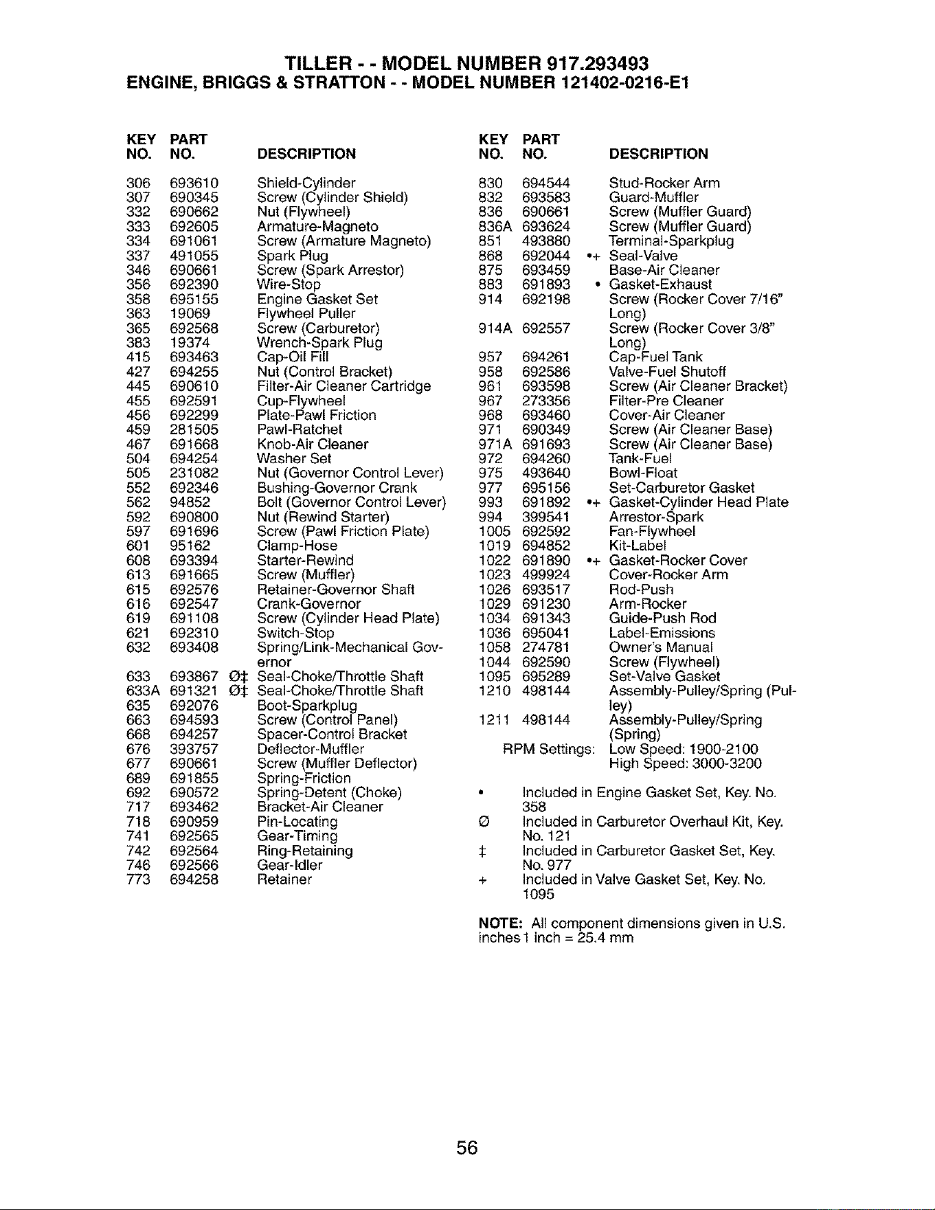
TILLER - - MODEL NUMBER 917.293493
ENGINE, BRIGGS & STRATTON - - MODEL NUMBER 121402-0216-E1
KEY PART KEY PART
NO. NO. DESCRIPTION NO. NO. DESCRIPTION
306 693610 Shield-Cylinder 830 694544 Stud-RockerArm
307 690345 Screw (Cylinder Shield) 832 693583 Guard-Muffler
332 690662 Nut (Flywheel) 836 690661 Screw (Muffler Guard)
333 692605 Armature-Magneto 836A 693624 Screw (Muffler Guard)
334 691061 Screw (Armature Magneto) 851 493880 TerminaI-Sparkplug
337 491055 Spark Plug 868 692044 ,+ Seal-Valve
346 690661 Screw (Spark Arrestor) 875 693459 Base-Air Cleaner
356 692390 Wire-Stop 883 691893 ° Gasket-Exhaust
358 695155 Engine Gasket Set 914 692198 Screw (Rocker Cover 7/16"
363 19069 Flywheel Puller Long)
365 692568 Screw(Carburetor) 914A 692557 Screw (Rocker Cover 3/8"
383 19374 Wrench-Spark Plug Long)
415 693463 Cap-Oil Fill 957 694261 Cap-Fuel Tank
427 694255 Nut (Control Bracket) 958 692586 Valve-Fuel Shutoff
445 690610 Filter-Air Cleaner Cartridge 961 693598 Screw (Air Cleaner Bracket)
455 692591 Cup-Flywheel 967 273356 Filter-Pre Cleaner
456 692299 Plate-Pawl Friction 968 693460 Cover-Air Cleaner
459 281505 PawI-Ratchet 971 690349 Screw (Air Cleaner Base)
467 691668 Knob-AirCleaner 971A 691693 Screw (Air Cleaner Base)
504 694254 Washer Set 972 694260 Tank-Fuel
505 231082 Nut (Governor Control Lever) 975 493640 Bowl-Float
552 692346 Bushing-Governor Crank 977 695156 Set-Carburetor Gasket
562 94852 Bolt (Governor Control Lever) 993 691892 ,+ Gasket-Cylinder Head Plate
592 690800 Nut (Rewind Starter) 994 399541 Arrestor-Spark
597 691696 Screw (Pawl Friction Plate) 1005 692592 Fan-Flywheel
601 95162 Clamp-Hose 1019 694852 Kit-Label
608 693394 Starter-Rewind 1022 691890 ,+ Gasket-Rocker Cover
613 691665 Screw(Muffler) 1023 499924 Cover-RockerArm
615 692576 Retainer-Governor Shaft 1026 693517 Rod-Push
616 692547 Crank-Governor 1029 691230 Arm-Rocker
619 691108 Screw (Cylinder Head Plate) 1034 691343 Guide-Push Rod
621 692310 Switch-Stop 1036 695041 Label-Emissions
632 693408 Spring/Link-Mechanical Gov- 1058 274781 Owner's Manual
ernor 1044 692590 Screw (Flywheel)
633 693867 Q:I: Seal-Choke/Throttle Shaft 1095 695289 Set-Valve Gasket
633A 691321 Q:I: Seal-Choke/Throttle Shaft 1210 498144 Assembly-Pulley/Spring (Pul-
635 692076 Boot-Sparkplug ley)
663 694593 Screw (Control Panel) 1211 498144 Assembly-Pulley/Spring
668 694257 Spacer-Control Bracket (Spring)
676 393757 Deflector-Muffler RPM Settings: Low Speed: 1900-2100
677 690661 Screw (Muffler Deflector) High Speed: 3000-3200
689 691855 Spring-Friction
692 690572 Spring-Detent (Choke) • Included in Engine Gasket Set, Key.No.
717 693462 Bracket-Air Cleaner 358
718 690959 Pin-Locating O Included in Carburetor Overhaul Kit, Key.
741 692565 Gear-Timing No. 121
742 692564 Ring-Retaining :I: Included in Carburetor Gasket Set, Key.
746 692566 Gear-Idler No. 977
773 694258 Retainer + Included in Valve Gasket Set, Key.No.
1095
NOTE: All component dimensions given in U.S.
inches1 inch = 25.4 mm
56

57

58

59

Get it fixed, at your home or ourst
Your Home
For repatr- in your home - of all major brand apphances,
lawn and garden equtpment, or heahng and coohng systems,
no matter who made it, no matter who sold it!
For the replacement parts, accessones and
owner's manuals that you need to do-it-yourself.
For Sears professional _nstallahon of home apphances
and _tems hke garage door openers and water heaters.
1-800-4-MY-HOME _ Anytime, day or night
(1-800-469-4663) (U S A and Canada)
www.sears.com www.sears.ca
Our Home
For repair of carry-m products hke vacuums, lawn equtpment,
and electronics, call or go on-hne for the nearest
Sears Parts and Repair Center.
1-800-488-1222 Anytime, day or night (U.S.A. only)
www.sears.com
To purchase a protection agreement (U.S.A.)
or maintenance agreement (Canada) on a product serviced by Sears:
1-800-827-6655 (u S _) 1-800-361-6665 (Canada)
Para pedtr ser_cio de reparaciSn
a dom_ciho,y para ordenar p=ezas:
1-888-SU-HOGAR sM
(1-888-784-6427)
Au Canada pour service en franq.als:
1-800-LE-FOYER Mc
(1-800-533-6937)
www sears ca
SEARS
© Sears,Roebuckand Co
®Regtstered Trademark / TMTrademark / st1Service Mark of Sears, Roebuck and Co
® Marca Regtstrada / TMMarca de Fabnca / sr,_Marca de Servtcto de Sears, Roebuck and Co
MCMarque de commerce / rid Marque d#posee de Sears, Roebuck and Co
186038 Rev. 1 05.12.03 TR Printed in U.S.A.