Operator's
Manual
HP50
Pellet Stove
WWW.COMFORTBILT.NET

TABLE OF CONTENTS
Safety Precautions...........................3-6
Introduction and Pellets......................7
Safety and Other Features..................8
Specifications.......................................9
Installation and Placement................10
Floor Protection Requirements........10
Clearances to Combustibles.............11
Stove Venting................................12-14
Outside Air Connection.....................15
Mobile Home Installation...................15
Stove Venting Examples..............16-21
Controller Operations...................22-23
Pre-Operation.....................................24
Startup and Operation Modes...........25
Setting Data on Controller...........26-28
Diagnostics.........................................29
Maintenance and Care..................30-32
Troubleshooting & Warranty............33
WARNING
Please read this entire manual before
installation or use of this pellet fuel-
burning room heater. Failure to follow
these instructions may result in property
damage, bodily injury, or even death.
Do not store or use gasoline or other
flammable vapors and liquids in the
vicinity of this or any other appliance
Do not overheat - If any external
component starts to glow, the stove is
overheating. Reduce the feed rate as
over-firing will void the warranty
Comply with all minimum clearances to
combustibles as specified. Failure to
comply may cause a house fire.
WARNING
HOT! Do not touch. Severe burns
and/or the ignition of clothing may
occur. Glass and other surfaces are hot
during operation and cool down.
Keep children away
Carefully supervise children in
same room as appliance.
Do not operate without
protective barriers in place.
Keep clothing, furniture,
draperies, and other flammable
materials away.
CAUTION
Check building codes prior to installation. Contact
the regulating authority prior to installation to
determine the need for a permit.
Installation must comply with local, regional,
state, and national codes and regulations.
Consult local building or fire officials about
restrictions or inspection requirements in your
area.
Important operating and maintenance
instructions included.
Read, understand, and follow these
instructions for safe installation and
operation.
This manual is to be left with the party
responsible for use and operation.
CAUTION
DO NOT DISCARD!
3

OWNER'S RESPONSIBILTY
Proper assembly, safety, and use of the
stove is the owner's responsibility.
Read and follow all safety instructions.
Carefully follow all assembly instructions.
Maintain the stove according to the directions
and schedule provided within this operator's
manual.
Ensure that anyone who operates the stove is
familiar with all controls and safety
precautions.
SPECIAL MESSAGES
This Manual contains special messages to bring
attention to potential safety and product
damaging concerns, as well as helpful operating
and servicing information. Please read all of the
information carefully to avoid potential injury and
stove damage.
NOTE: General information is given
throughout the manual that may aid in the
operation or service of the stove.
IMPORTANT SAFETY PRECAUTIONS
Please read this section carefully.
Operate the stove according to the safety
instructions and recommendations outlined here
and inserted throughout the text. Anyone who
uses this stove must read the instructions and be
familiar with the controls
This symbol points out important
safety instructions which, if not
followed, could endanger your
personal safety. Read and follow all
instructions in this manual before
attempting to operate this
equipment.
4
You must read, understand, and comply with all
safety and operating instructions in this manual
before attempting to setup and operate your stove.
Failure to comply with all safety and operating
instructions can result in serious personal injury to
you and/or bystanders, and/or property damage.
DANGER
Indicates a serious injury or fatality WILL result if
the safety instructions that follow this signal word
are not obeyed.
WARNING
Indicates a serious injury or fatality COULD result
if the safety instructions that follow this signal
word are not obeyed.
CAUTION
IMPORTANT
Indicates minor or moderate injury to you or your
property COULD result if the safety instructions
that follow this signal word are not obeyed.
Indicates helpful information for proper assembly,
operation, or maintenance of your equipment.
WARNINGS AND SAFETY
PRECAUTIONS

Read this entire manual before you install and
use your new pellet stove. Failure to follow
instructions may result in property damage,
bodily injury, or even death.
Children and adults should be alerted to the
hazards of high surface temperatures and
should avoid contact to skin and/or clothing.
Young children should be carefully supervised
when they are in the same room as the stove
Clothing and other flammable materials should
not be placed on or near this unit
Flammable or explosive liquids such as gasoline,
naphtha, alcohol, or engine oil must NEVER be
used in or around stove. These liquids must be
stored in a separate room as the open flame in
the fire box could ignite the fumes of such
liquids.
WARNING
Proper installation of this stove is necessary for
safe and efficient operation. Installing this product
improperly may result in a house fire and/or
personal injury.
All applicable building codes for your location must
be followed. In areas where building codes require
additional steps to the installation of this product not
included in this manual, the building codes will take
precedence and must be followed. Contact your
local building inspector to obtain any necessary
permits or inspection guidelines before installing the
product.
WARNING
CAUTION
Tested and approved for pellet fuel. Burning
any other type of fuel voids warranty.
5
WARNING
If the electrical power fails at any time when
the stove is hot, keep all stove doors closed.
The automatic safety features must not be
bypassed.
CAUTION
Burning wood pellets according to recommendations
will assure longer stove life and less fuel related
problems. The use of grates or other methods of
supporting the fuel in this stove is prohibited and will
void all warranties.
DO NOT
Burn garbage in this unit. The burning of
other solid fuels such as cord wood or wood
chips in this stove is not permitted. Any
fuels not certified which are burned in this
stove will void the warranty
Route power cord in high traffic areas. A
power surge protector plugged into a
grounded 230 volt power source is required.
Install a flue damper in the exhaust venting
system of this unit.
Connect this unit to a chimney flue servicing
another appliance
Install in a sleeping room.
Connect to any air distribution duct or
system.
Connect directly to a masonry chimney
Terminate vent in any enclosed or semi-
enclosed area, such as; carports, garage,
attic, crawl space, under a sun deck or
porch, narrow walkway or closed area, or
any location that can build up a
concentration of fumes such as a stairwell,
covered breezeway etc
NEVER touch door latches or heat tube
scraper while stove is in operation; they get
extremely hot.
WARNING

6
All applicable building codes for your location
must be followed. In areas where building codes
require additional steps to the installation of this
product that are not included in this manual, the
building codes will take precedence and must be
followed. Contact your local building inspector to
obtain any necessary permits or inspection
guidelines before installing the product.
Contact local building or fire officials about
restrictions and installation inspection
requirements in your area
Contact your local authority (such as municipal
building department, fire department, fire
prevention bureau, etc.) to determine the need
for a permit
This pellet stove is designed to burn pellet fuel
only
A working smoke detector is required and must
be installed in the same room as the stove.
This stove is not intended for use in
commercial applications
Door and ash pan must be closed and latched
during operation
Notify your insurance company of pellet stove
installation
This installation must conform with local codes.
In the absence of local codes you must comply
with EN 14785.
The structural integrity of the manufactured
home floor, wall, and ceiling/roof must be
maintained.
Keep combustible materials (such as grass,
leaves, etc.) at least three feet away from the
flue outlet on the outside of the building.
This stove should not be used as the only
source of heat in the house. Power outages
and periodic maintenance will result in a total
loss of heat.
Do not leave hopper door open while
unattended.
CAUTION CAUTION
Installation and repair of this pellet stove
should be done by a qualified service person.
The appliance should be inspected before
use and at least once per year by a qualified
service person. It is imperative that the control
compartments, fire box, and circulating air
passageways of the stove are kept clean.
The operation of exhaust fans such as
bathroom fans, attic fans, etc... might starve
the pellet stove of combustible air, creating a
negative pressure in the room. Provide
adequate ventilation of the room the stove is
installed in, otherwise the pressure switch may
shut off operation of the pellet stove.
The moving parts of this stove are propelled
by high torque electric motors. These parts
can cause severe damage to body parts that
get near them. Keep all body parts away from
auger and fans while the stove is plugged into
an electrical outlet. Moving parts are subject
to begin moving while power is supplied.
The venting surfaces can become hot enough
to cause burns if touched. Non combustible
shielding or guards may be required.
Install all venting at the clearances specified
by the vent manufacturer. All venting joints,
whether vertical or horizontal, should be made
gas-tight with recommended sealants
specified by vent manufacturer.
According to HUD (Housing & Urban
Development) requirements, when installing
within a mobile home, this stove must be
grounded directly to the steel chassis of the
mobile home, and bolted to the floor. Direct air
access must be provided by way of a fresh air
intake kit.
For use in the United States and Canada.
Approved for installation in mobile homes.
Producer of this appliance reserves the right to
alter its products, specifications, and/or price
without notice.

INTRODUCTION
Congratulations on your investment in quality. We
have worked hard to ensure that this pellet stove
meets the highest standards for usability and
durability. With proper care, your stove will provide
many years of dependable service. Please read
entire manual before installation and use.
Complies with the ASTM E1509, (UM) 84-HUD,
ULC/ORD-C-1482.
U.S. Environmental Protection Agency Certified to
comply with 2020 particulate emission standards
using pellet fuel.
BURNING PELLET FUEL
Ashes need to be removed from the stove
periodically. See Normal Care & Maintenance
section for cleaning procedures.
Due to the nature of pellet fuels, this stove will
require attention periodically. Regular cleaning is
an important part of burning pellet fuel.
PELLETS
This pellet stove is designed and approved to
burn wood pellets, that comply with pellet fuels
industry standards. Minimum of 40 lbs. density
per cubic foot, 1/4" to 5/16" in diameter, with a
maximum length of 1" to 1/2", and less than 1%
ash.
The performance of your pellet stove is greatly
affected by the type and quality of the wood
pellets you use. As the heat output of various
quality wood pellets differ, so too will the
performance and heat output of the pellet stove.
Wood pellets are generally produced out of
wood waste such as sawdust and shavings.
The raw material is dried, mechanically
fractioned to size and extruded into pellets
under high pressure. Wood pellets need to be
protected from direct exposure to moisture.
Water, from sources such as condensation and
humidity, causes pellets to expand and break
down into unusable fuel. Keep fuel dry.
It is important to select and use only pellets that
are dry and free from dirt and debris. Dirty fuel
will adversely affect the operation and
performance of the unit, and will void the
warranty. The Pellet Fuel Institue (PFI) has
established standards for wood pellet
manufactuerers. Only use pellets that meet or
exceed PFI standards for premium fuels.
7
CLINKERS
Impurities, such as silica (clinkers), will need to be
regularly cleaned and removed from the pellet
stove. Clinkers will form a hard mass and block
airflow through the pot liner. High quality fuels will
usually result in fewer clinkers.
Pellet fuel quality can greatlly fluctuate. The unit
was tested with premium grade pellets. You
cannot use a lesser grade, but higher grades can
be used.
Do Not Burn:
Garbage
Lawn clippings or yard waste.
Materials containing rubber, including tires.
Materials containg plastic.
Waste petroleum products, paints or paint
thinners, or asphalt products.
Materials containing asbestos.
Construction or demolition debris.
Railroad ties, or pressure-treated wood.
Manure or animal remains
Paper products, cardboard, plywood, or
particleboard. The prohibition against using
these materials does not prohibit the use of fire
starters made from paper, cardboard, saw dust,
wax and similar substances for the purpose of
starting a fire in an affected wood heater.
Burning these materials may result in the release of
toxic fumes or render the heater ineffective and
cause smoke.
1.
2.
3.
4.
5.
6.
7.
8.
9.
10.
AUTOMATIC SAFETY FEATURES
During a power outage, the stove will shut down
safely. Do not open the main door or ash pan
door. During a power failure, the exhaust fan will
not run. Keeping the doors sealed will allow the
exhaust vent to draft out naturally. When the
power is restored, the stove will not restart. If the
exhaust temperature is still 120 degrees
Fahrenheit when power is restored, the exhaust
and convection fans will continue to run until the
stove cools. See lighting instructions to restart
stove.
POWER OUTAGE
OVERHEATING
Over Fire Protection: If the stove is being over
fired or burning too hot, the high limit switches will
automatically shut down the stove to avoid
damage to other components. If the temperature
on the hopper reaches 200 degrees Fahrenheit,
the auger will automatically stop and the stove will
shut down. The exhaust fan will continue to run
until the proof of fire switch cools. Allow the stove
to cool before attempting to re-ignite. See Start-
Up.
UNDERSTANDING YOUR STOVE
Your stove utilizes a vertical auger fuel feed system
that is operated by a microprocessor controlled
digital circuit board. The digital circuit board allows
the vertical auger fuel system to run in a timer
based, non-continuous cycle. This cycling allows
the auger to run for a predetermined amount of
time. The auger pushes pellets up a chute located
in the hopper. The pellets will then turn and fall
through another chute into the burn pot. Your stove
is equipped with an automatic ignition system that
should ignite the fuel within 3-5 minutes of pressing
the On/Off button. As pellets fill the burn pot and
ignite, outside air is drawn across the fuel and
heated during the combustion process with is then
pulled across the heat exchange tubes by the
exhaust motor. As the stove reaches operating
temperature, the room air is then circulated around
the heat exchange tubes by a room air blower,
distributing warm air into the room. The amount of
heat that is produced by the stove is proportional to
the rate of fuel that is burned. Because a forced
draft pressure is required for the combustion
process inside the stove, it is extremely important
that the exhaust system be properly installed and
maintained. Also, the doors must remain closed
while in operation and the seals on the doors must
be properly maintained.
Install at least one smoke detector on each floor
of your home to ensure your safety. They should
be located away from the stove, and close to the
sleeping areas.
You should have separate CO monitors for areas
near the stove
8
OTHER STOVE FEATURES
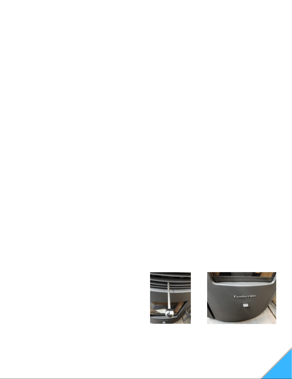
Exchange Tube Scraper: Scrapes the carbon
buildup that can accumulate on the heat-transfer
tubes. Never touch while stove is Hot.
See Figure A
Glass Air Wash System: Allows the stove to
draw in air, through the lined up slots, to gently
wash against the interior of the glass to help
keep it free of soot buildup. To the right is open,
to the left is closed. See Figure B
Figure A: Scraper Figure B: Glass Airwash
9
SPECIFICATIONS
GLASS SPECIFICATIONS
This stove is equipped with 1 pane of ceramic glass.
Replace glass only with Qualified ceramic glass.
Model Number
BTU/Hour Output (1)
Heating Capacity (2)
Particulate Emissions
Efficiency
Power Consumption
Power Consumption
Fuel Storage Capacity
Exhaust Size
Width
Height
Depth
Weight
Exhaust center to floor
Exhaust center to side
Room Blower CFM
HP50
16,000 - 42,000
Up to 2,200 sq. ft.
1.93 g/hr
81%
450 Watte Startup
150 Watts Operation
47 lbs
3" Standard
20.5"
34"
23.5"
237 lbs
11"
4"
127 CFM
WARNING
If you see black smoke at the end of the
exhaust/chimney, these are not normal emissions.
Check for clinkers or blockages in the burn pot.
Check for leakages around the stove, such as
glass door or ash pan.
Check for potential blockages in the exhaust
channels.
Check that the exhaust voltages are correctly set.
1.
2.
3.
4.
WARNING
(1) Heat output will vary depending on the brand,
type and quality of fuel, and the moisture content.
Consult your dealer for best results.
(2) Based on post 1982 home construction,
requiring 35 BTU/Hr. per Sq. Ft.
Emissions will vary, depending on the feed
level, burning time, and fuel. Consult your
dealer for best results.
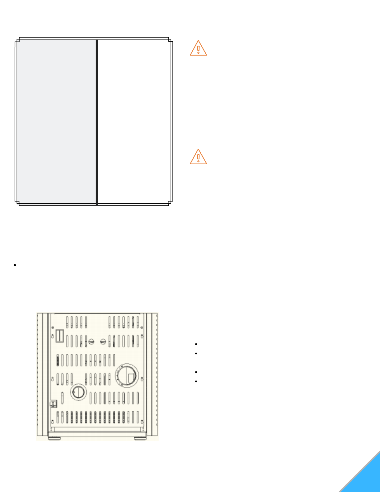
Figure 1: Intake and exhaust positions
UNPACKING
Your stove will come fully assembled.
Remove all packing material and tape from the inside
of the firebox.
Remove any tape on the outside of the glass.
Open hopper, and remove all packing material and
power cord.
Note: Make sure the hopper is free of all forign matter
before filling with fuel. Forign material will cause auger
jams and will void stove warranty.
This stove has a manufacturer set minimum low
burn rate that must not be altered. It is against
federal regulations to alter this setting or otherwise
operate this stove in a manner inconsistent with the
operating instructions within this manual. If the unit
is modified, it will no longer be compliant with the
EPA regulations.
10
INSTALLATION
It is recommended that the stove be installed and
serviced by an authorized professional.
Proper installation of this stove is necessary for safe
and efficient operation. Installing this product improperly
may result in a house fire and/or personal injury.
STOVE PLACEMENT
Sketch out a plan for installing the stove, including
dimensions, before permanent placement. When
determining the location for the stove, wall stud location
is critical. You may need to adjust the location of the
stove to avoid encountering a wall stud. Before placing
the pellet stove, connect the vent to allow for minimum
clearance to combustable walls.
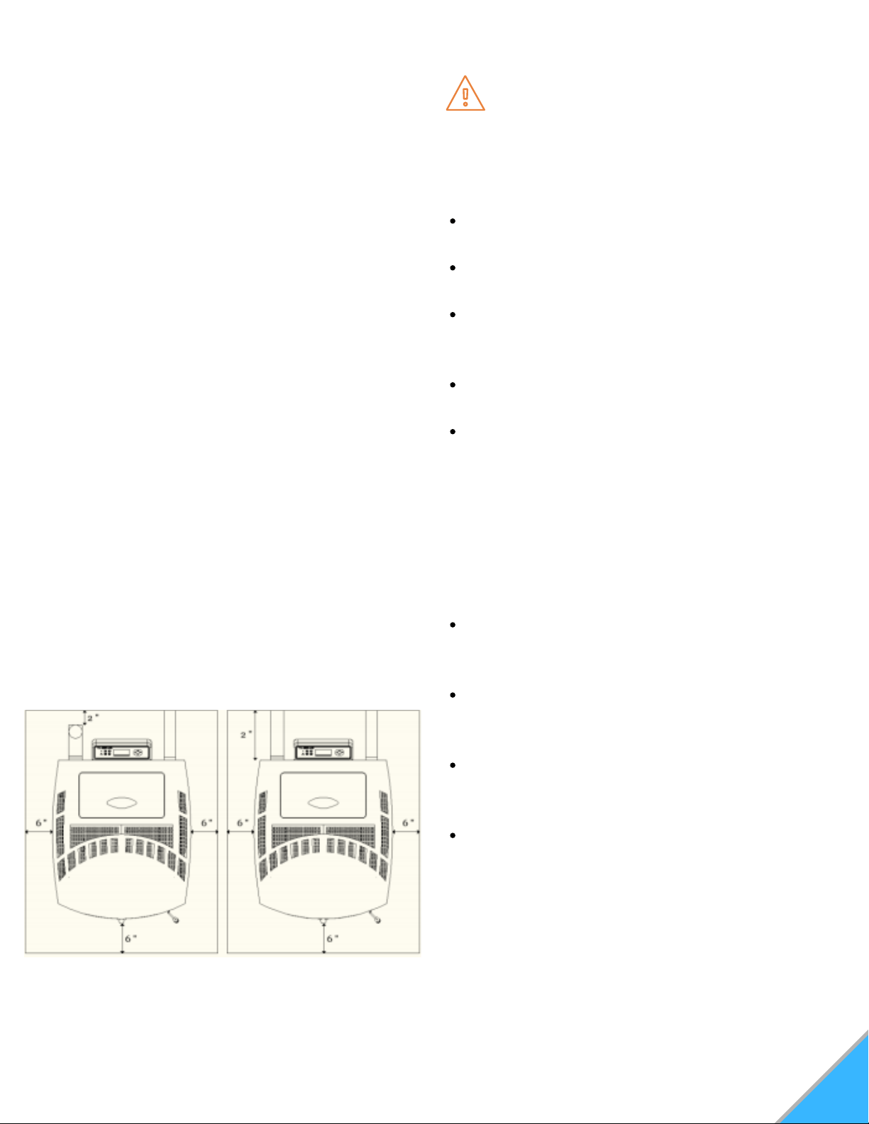
FLOOR PROTECTION REQUIREMENTS
The stove must be installed on a noncombustible floor,
with proper floor protection, or on a masonry hearth.
When a clean out T-vent is installed on the inside of a
home, the floor protector must extend 2" beyond the rear
of the T-vent. See Figure 2
When stove is vented straight through the wall and the
clean out T-vent is on the exterior of the home, the
minimum clearance is 2" from the back of the stove to
the wall. See Figure 3
Figure 2 Figure 3
Figures 2 and 3: Pellet stove floor pad clearances
WARNING
Read this entire manual before you install and use
this stove. Failure to follow the instructions may
result in property damage, bodily injury, or even
death.
Do not install a flue damper in the exhaust
venting system of this unit.
Do not connect this unit to a chimney flue that
services another appliance.
Children and adults should be aware of the
hazards of high surface temperatures and should
stay away to avoid burns to skin and/or clothing.
Young children should be carefully supervised
when they are in the same room as the stove.
Clothing and other flammable materials should
not be placed on or near this unit.
CAUTION
This stove should not be used as the only source of
heat in the home. Power outages and periodic
maintenance will result in a total loss of heat.
Contact local building or fire officials regarding
restrictions and installation inspection
requirements for your area.
Contact your local authority (Municipal building
department, Fire department, Fire prevention
bureau, etc...) to determine the need for a permit.
Keep combustible materials (such as grass,
leaves, etc...) at least 3 feet away from the flue
outlet on the outside of the building.
Installation and repair of this pellet stove should
be done by a qualified service person. The
appliance should be inspected before use, and at
least annually by a qualified service person. It is
imperative that the control compartments, fire
box, and circulating air passageways of the stove
be kept clean.
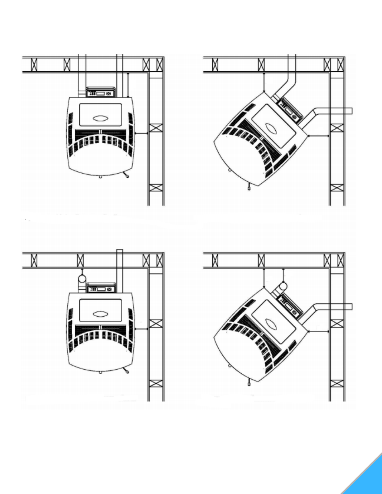
CLEARANCES TO COMBUSTIBLES
NOTE: These are minimum clearances to combustible walls.
3"
3"
3"
3"
2"
2"
6"
6"
Figure 5: Corner Insallation through wallFigure 4: Straight Insallation through wall
Figure 6: Straight Insallation interior vertical vents Figure 7: Corner Insallation interior vertical vents
NOTE: When Interior Vent is installed vertically, the clearance to the back wall is determined by the vent size
used. Install vent at clearance specified by the vent manufacturer. Take into consideration any upward turning
elbows or tees.
11
2"

VENTING
Before venting, consult vent manufacturer's
specifications and recommendations for all
venting installations.
The following installation guidelines must be
followed to ensure conformity with both the safety
listing of this stove and to local building codes.
TYPE OF VENT
The pellet venting pipe (also known as L vent) is
constructed of two layers with air space between
the layers. This air space acts as an insulator and
reduces the outside surface temperature of pipe to
allow a clearance to combustibles. A cap must be
used at the termination of type L vent chimneys.
For elevations above 5,000 feet above sea level, 4"
venting is required.
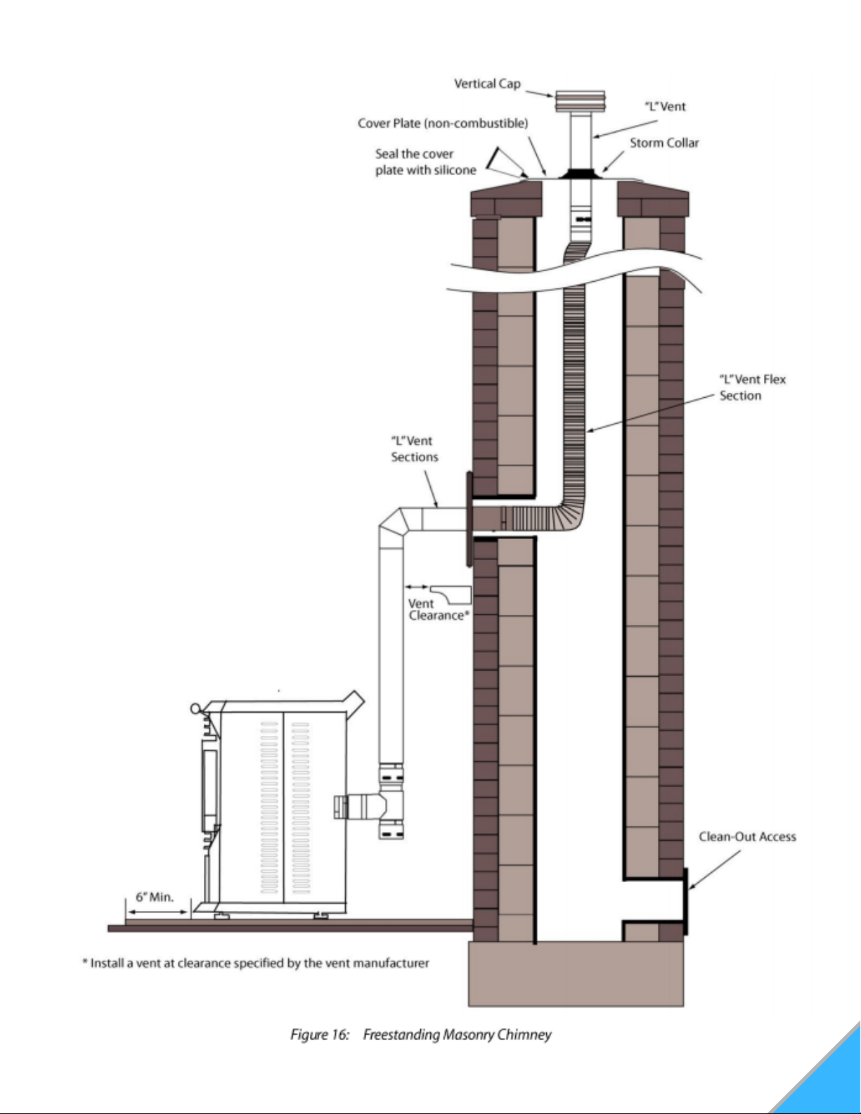
PELLET VENT INSTALLATION
Vent termination MUST exhaust above the
elevation of the air inlet. It is recommended to
install at least 3 feet of vertical pellet vent pipe.
This vertical pipe will create some natural draft to
reduce the possibility of smoke or odor during
appliance shutdown, and will keep exhaust from
causing a nuisance or hazard from exposure to
high temperatures.
The installation must include a clean out tee to
enable the collection of fly ash and to permit
periodic cleaning of the exhaust system. Total
length of horizontal vent must not exceed 10 feet.
The maximum recommended vertical venting
height is 18 feet.
All joints for pellet vent are required to be
fastened with at least three screws and
all connections (including adapters,
elbows, etc...) should be sealed airtight
by injecting 500° F RTV silicone into the
gap between sections.
The area where the vent pipe goes
through to the exterior of the home must
be sealed with silicone or other means to
maintain the vapor barrier between the
exterior and the interior of the home.
12
WARNING
Do Not connect this unit to a chimney flue that
services another appliance.
Do Not install a flue damper in the exhaust
venting system of this unit.
Do Not connect directly to a masonry chimney.
Do Not terminate vent in any enclosed or semi-
enclosed area, such as; Carport, garage, attic,
crawl space, under a sun deck or porch, narrow
walkway, or any location that can build up a
concentration of fumes such as a stairwell,
covered breezeway, etc...
CAUTION
Vent surfaces can get hot enough to cause burns if
touched. Non-combustible shielding or guards may
be required.
Pellet vent must maintain minimum clearances
to combustibles specified by vent manufacturer.
Install vent at clearances specified by the vent
manufacturer.
All venting joints, whether vertical or horizontal,
should be made gas tight with recommended
sealants.
WARNING
Never shut the stove down by unplugging it from
the power source.
Never shut the stove down from by switching off
the main power switch on the rear of the stove.
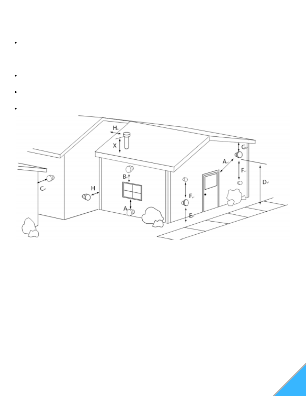
PELLET VENT TERMINATION CLEARANCE
The stove vent must terminate on the outside of the building. Horizontal terminations must extend a
minimum of 12" from the wall. Vertical terminations must protrude a minimum of 24" from the roof
surface.
In addition, all clearances listed below must be met. SEE FIGURE 8
Must have an approved cap (to prevent water from entering) or a 45 degree downturn with rodent
screen.
If the termination is located on a windy side of the house, we suggest using an approved house shield
to prevent soot from building up on the side of the house.
A vent must not be located where it may become plugged by snow or other material.
Figure 8: Vent Termination
A: Minimum 48" clearance below or beside any door or window that opens. (This clearance may be
reduced to 18" if using outside air). We recommend the door or window be kept closed during operation.
Minimum 12" clearance below or beside any window that does not open.
B: Minimum 12" clearance above any door or window that opens.
C: Minimum 24" clearance from any adjacent building.
D: Minimum 7' clearance above any grade, when adjacent to public walkways.
E: Minimum 24" clearance above any grass, plants, or other combustible materials.
F: Minimum 36" clearance from any forced air intake of another appliance.
G: Minimum 24" clearance below eaves or overhangs.
H: Minimum 12" clearance horizontally from combustible wall.
X: Must be a minimum of 24" above the roof.
NOTE: May not vent into covered walkway or breezeway.
13
14
VENTING THE PELLET STOVE
Do not install flue damper in the exhaust
venting system of this unit.
Use an approved wall thimble when
passing the vent through walls. Use a
ceiling support/fire stop spacer when
passing the vent through ceilings. (Make
sure to maintain minimum clearances to
combustibles)
If using more than one T-vent or exceed
180° of elbows, you must use 4" venting
pipe.
NOTE: In order to achieve optimum
performance, it is recommended that you keep
the vent as short as possible, especially in
regards to the horizontal run.
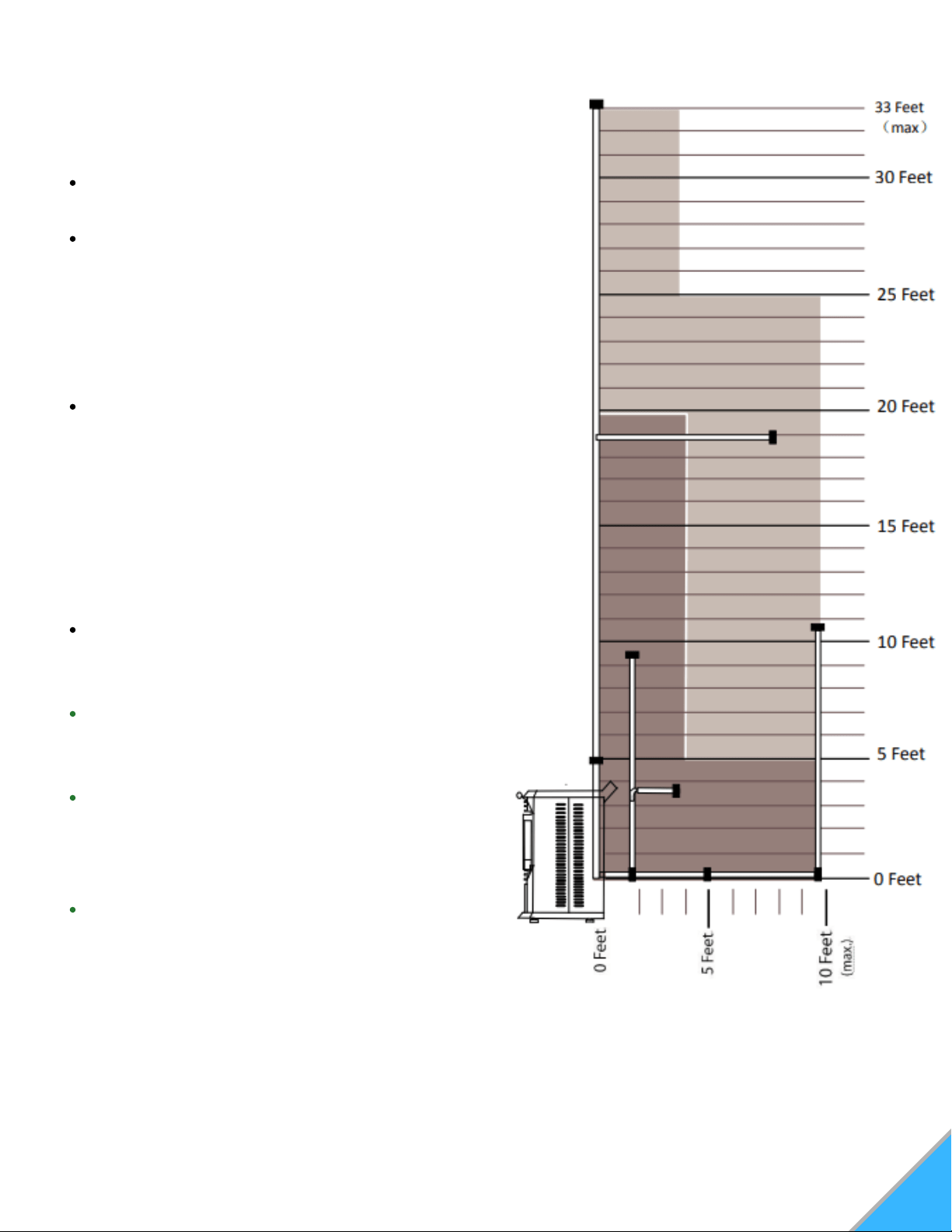
The vent must have a support bracket
every 5' of pellet vent when on the exterior
of the structure.
The vent height and run must not exceed
the distance as illustrated in diagram
Figure 9.
Venting into the lighter shaded area may
require combustion motor voltage
adjustments and/or inlet air adjustments
(intake).
See Figure 9
Figure 9: Venting and combustion motor
voltage adjustment chart

OUTSIDE AIR CONNECTION
Connection from the intake pipe (2" diameter
pipe in rear of stove) to the outside of the house
is REQUIRED for mobile home installation. It is
recommended in tightly sealed homes with
exhaust fans such as kitchen or bathroom fans,
or in basement installations. This will eliminate
poor performance due to negative pressure.
Only noncombustible pipe 2" (or greater) in
diameter is approved for outside air connections
(Straight of flexible). PVC pipe is NOT approved
and should NEVER be connected to the stove.
If the air inlet is connected to the outside, it
MUST be terminated with a vertical 90° bend
down, or with a wind hood. Failure to do so
could result in a burn-back if high winds blow
directly up the air inlet during a power outage.
Blockage, excessive length (more than 6-8 ft),
or extra bends in the air intake could lead to
starvation of combustible air to the stove.
15
MOBILE HOME
Installation in a mobile home should be in
accordance with the manufactured home and
safety standard (HUD), CFR 3280, Part 24. This
stove must be vented to the outside. In addition to
the standard installation instructions, the following
requirements are mandatory for installation in a
mobile home:
The stove must be permanently attached to the
floor.
Stove must have an outside air source.
Stove must be electrically grounded to the steel
chassis of the mobile home, unless 3-prong or
GFCI power outlets are provided.
All vertical chimney vents must have wall
supports.
All exhaust systems must have a spark arrestor.
Check with local building officials to see if other
codes may apply.
Structural integrity of the floor, wall and
ceiling/roof must be maintained.
1.
2.
3.
4.
5.
6.
7.
WARNING
Do not connect to any air distribution duct or
system.
Do not install in a sleeping room.
CAUTION
The operation of exhaust fans, such as bathroom
and attic fans, could create a negative pressure in
the room, causing the stove to be starved of
combustible air. Be sure to provide adequate
ventilation in the room the pellet stove is located. If
not, the pressure (vacuum) switch may shut off the
operation of the pellet stove.
The efficiency of ComfortBilt pellet stoves can be
impacted by the temperature of the air supplied to
the burn pot, and the temperature of the air that is
drawn past the heat exchange tubes to heat the
room. When exterior air supplied to the burn pot is
extremely cold, slightly more energy is required to
burn pellets at optimum temperatures. A
disadvantage of supplying interior room air to the
burn pot is that the room air used by the burn pot
(and sent out to the exhaust pipe) must be
replaced by air drawn through windows, doors,
and cracks. Using interior air is not recommended
in newer houses that are tightly sealed. Air drawn
in by the room blower is always interior room air
and should be the coolest air in the living space.
Stoves typically work best when placed on the
lower level of the home, and located so that all the
air in the space is freely available to the stove's
heat exchanger.
16
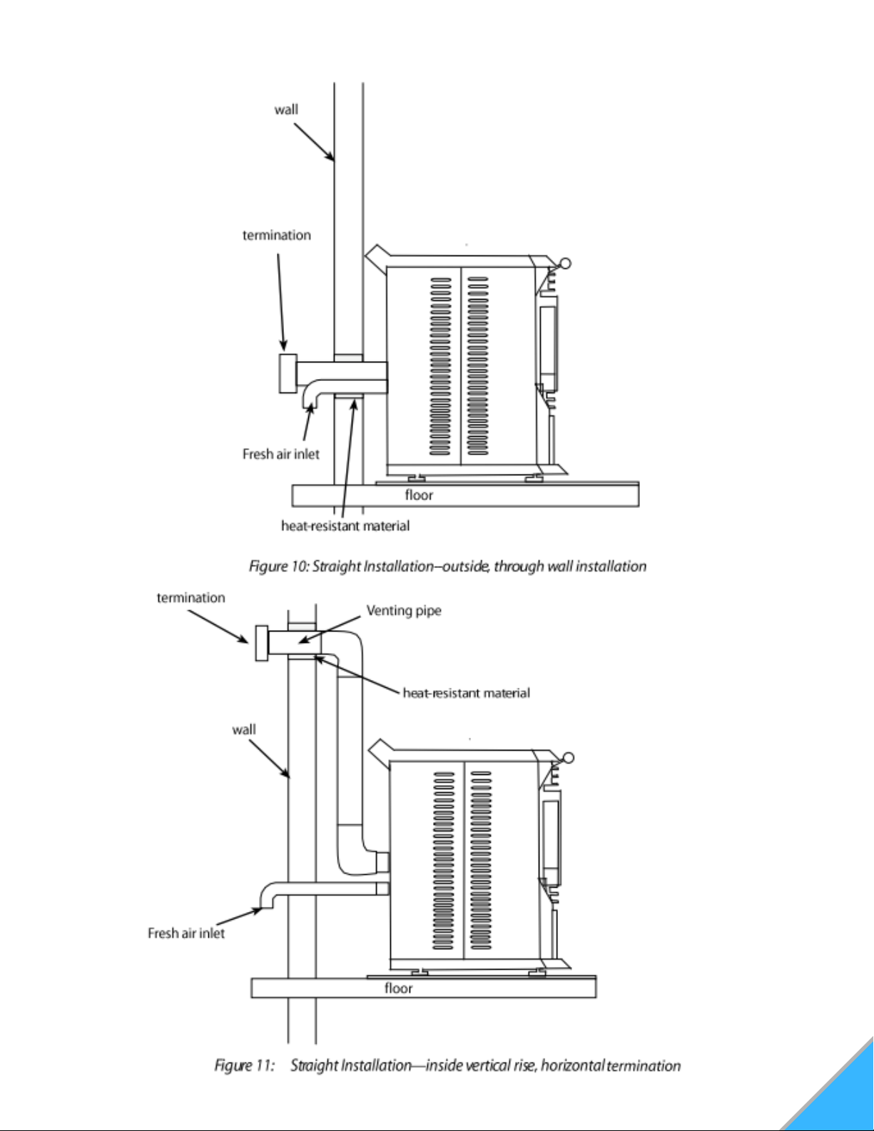
SIMPLE STOVE VENTILATION EXAMPLES
COMPLEX STOVE VENTILATION EXAMPLES
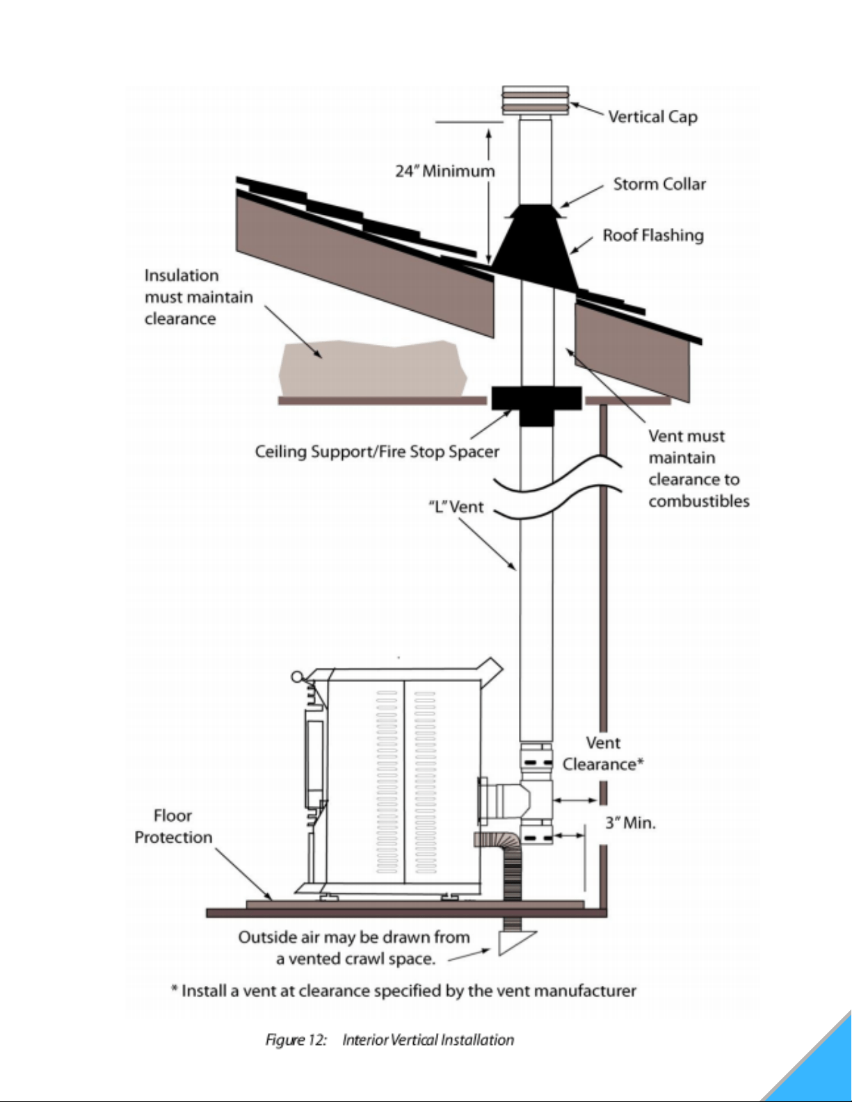
INTERIOR VERTICAL INSTALLATION
17
18
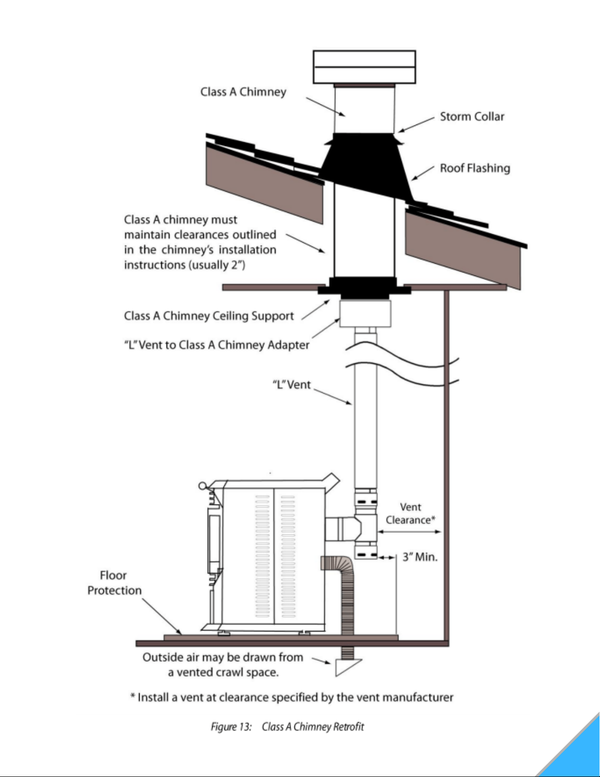
CLASS A CHIMNEY RETROFIT

19
MASONRY FIREPLACE HEARTH STOVE
20
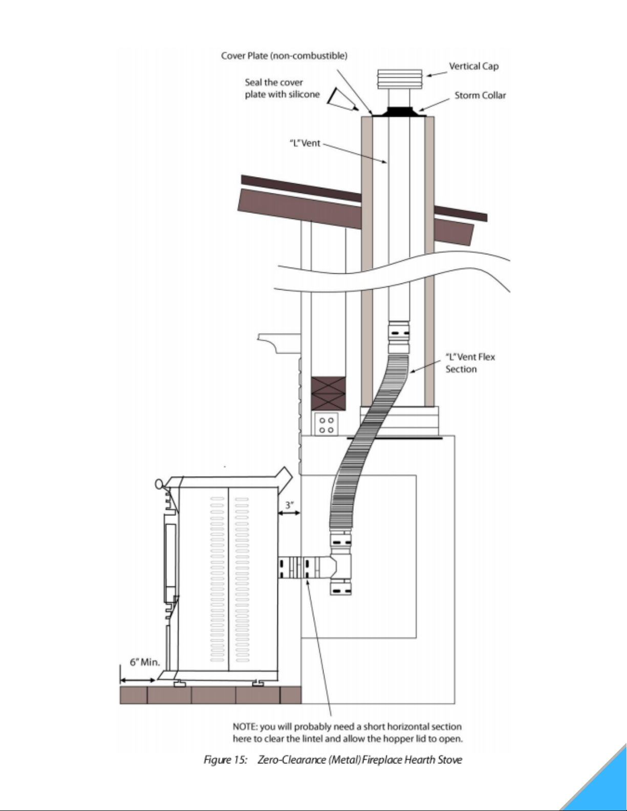
ZERO-CLEARANCE (METAL) FIREPLACE
HEARTH STOVE
21
FREESTANDING MASONRY CHIMNEY
22
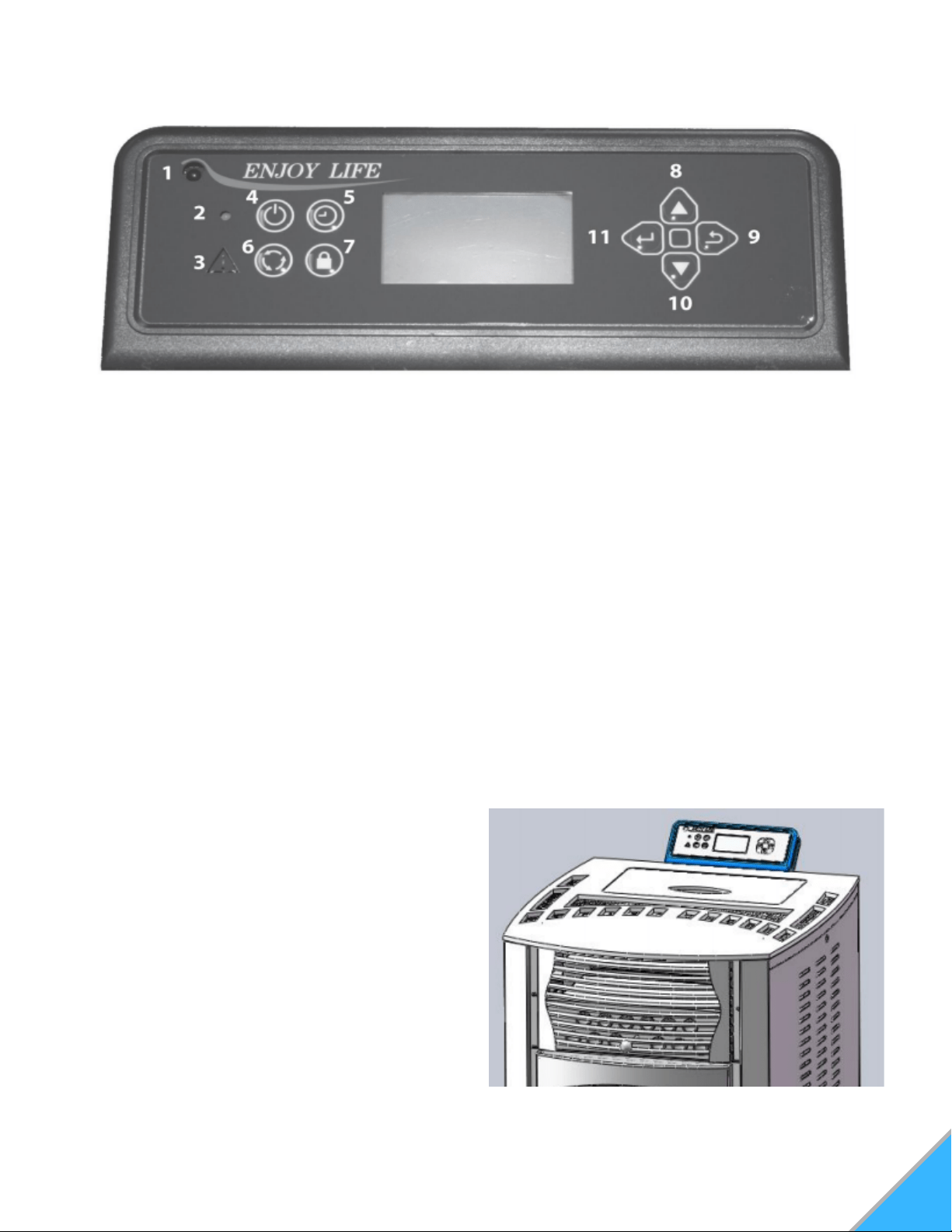
BECOMING FAMILIAR WITH YOUR CONTROLLER
Figure 18: Control pad location
Figure 17: Control keypad
CONTROLLER BUTTONS
Infrared Receiver: Receives signal from
remote control. (Available separately)
Power Indicator: Illuminates when main
power is switched on.
Alarm Light: Illuminates if stove is not
operating correctly.
On/Off Button: Starts and stops operation of
stove.
Timer Button: Allows you to choose the start
or shutdown time of the stove.
Mode Transfer Button: Allows you to set the
unit to one of three main mode settings:
Manual, Temp, and Weekly.
Hold Button: Pressing the "Hold" button in
weekly mode after raising the "call to
temperature" will maintain that temperature
until the button is pressed again or stove is
shut down.
Scroll up Button: Allows you to scroll up to
choose items in the menu.
Exit Button: Take you out of current
selection and returns to previous option
and/or screen. When entering data, pressing
the EXIT button will delete your entries.
Scroll Down Button: Allows you to scroll
down to choose items in the menu.
1.
2.
3.
4.
5.
6.
7.
8.
9.
10.
MOUNTING YOUR CONTROLLER
Mount the controller and the controller bracket to
top and back of your stove using the hardware
that accompanied the controller.
See Figure 18
11. Enter Button: Pressing "Enter" button allows
you to adjust and select data on the screen.
Pressing the "Enter" button for 3 seconds will take
you the a main menu screen in which you will
have the ability to change the time, date,
temperature display, weekly operation schedule
(for Weekly Mode only) and combustion motor
and voltage settings. See Figure 17
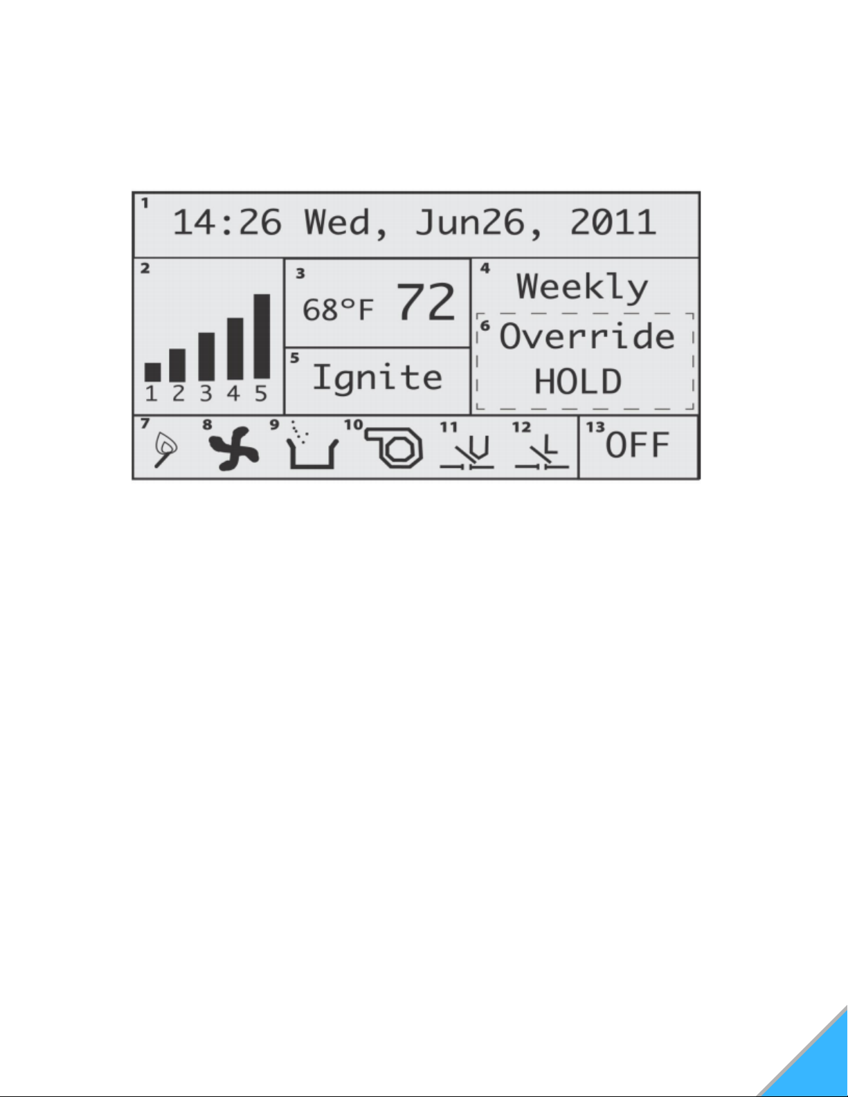
MAIN OPERATION CONTROLLER
SCREEN DISPLAY
Date and Time: Displays time and
date.
Heating Power Level: Indicates the
level of power at which the stove is
currently heating.
Current Room Temperature/Call To
Temperature: Displays current room
temperature and, in the Temp mode,
the call to temperature.
Main Mode: Displays Operation mode
- Weekly, Temp, and Manual.
Work Stage: Displays operational
stage in which the stove is currently
operating (i.e. Ignite, Heating)
Additional Control Mode: Displays
additional mode info such as holds
and overrides.
1.
2.
3.
4.
5.
6.
7. Igniter Indicator: Indicates when the
igniter is being fired.
8. Combustion Blower Indicator:
Indicates when the exhaust/combustion fan
is running.
9. Auger Indicator: Indicates when the
auger is feeding pellets.
10. Convection Blower Indicator:
Indicates convection/room blower fan is
running.
11. Vacuum Switch Indicator: Indicates
there is vacuum pressure in the stove.
12. Hopper Lid Open Indicator: Indicates
the hopper lid is closed. When lid is open,
"L" will disappear.
13. On/Off Mode Indicator: Indicates
when the stove is either on or off.
23
Figure 19: Display Screen
24
PRE-OPERATION
Once the stove has been properly installed and
plugged into a grounded surge protector, you are
ready to begin operation.
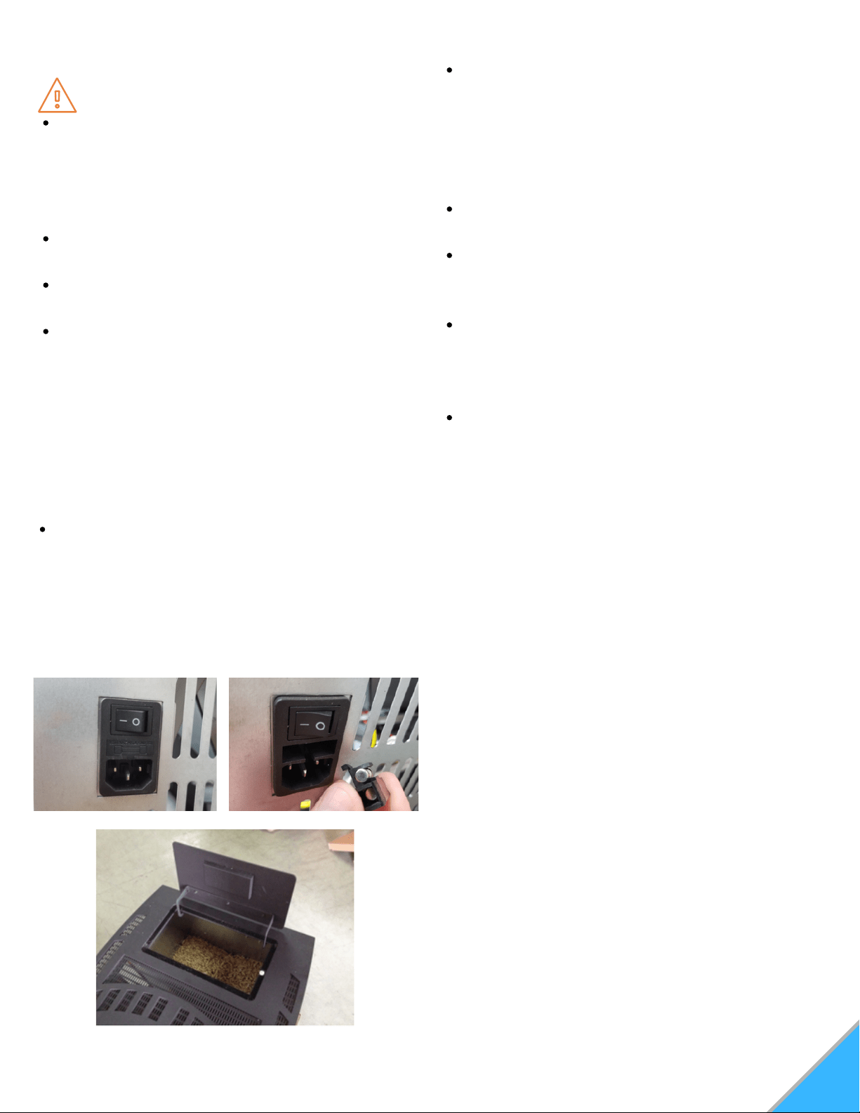
PRIOR TO STARTING
Turn on the main power switch located on the
back of the stove. See Figure 20A
NOTE: If for some reason the stove does not
appear to be powering on, there is a fuse
located just below the power switch that can be
checked. A spare fuse is located inside the
fuse holder if needed. See Figure 20B
Make sure the hopper is clean and free of
foreign matter, including pellet fines and dust.
Fill the hopper with wood pellets, making sure
that NO parts of the bag or any foreign objects
enter the hopper, as this may cause harm to
the auger feed system. See Figure 21
Also take care to ensure there is no pellet
material in the hopper lid seating surfaces.
Close the lid. This stove has a safety switch
that will not allow pellets to feed with the
hopper door open.
Ensure the main glass door is closed. This
stove has a safety switch that will not allow
pellets to feed unless there is a negative
pressure detected inside the stove.
Before actually starting your stove, you will
need to determine which operating mode you
would prefer the stove to run in. This stove can
operate in one of three modes.
Manual: In this mode, you can personally adjust
and set the heating power level to control the
heat level.
Thermostat Control (Temp): In this mode, you
can set the room temperature and the stove will
automatically adjust the heating power level to
maintain the desired temperature.
Weekly: In this mode, the stove will work
automatically during days and times you
predesignate. You can have a program for
each of the 7 days of the week, and up to 4
periods during the day.
You must select your mode before turning on the
stove.
Selecting a mode while the stove is burning may
cause the stove to shut down and may force a 30-
minute delay in restarting. You do not need to start
operation of the stove to select your mode. To
choose the mode, locate the mode transfer button
on the controller. (#6 in Figure 17)
Pressing the mode button once selects Temp
mode, pressing twice will select the Weekly mode,
pressing a third time will return you back to
Manual mode.
1.
2.
3.
WARNING
Never use flammable liquids such as gasoline,
gasoline-type lighter fuel, charcoal, lighter
fluid, or fire starting gels in or around the
stove. Keep all such liquids well away from
the stove when it is in use.
Never open the side panels or main door when
stove is in operation.
Never touch door latches while in operation,
they can get extremely hot.
Never open glass door while stove is operating
or while stove is hot.
Figure 20A: Power Switch Figure 20B: Spare Fuse
Figure 21: Pellet Load Hopper Lid

OPERATION
After you have chosen the desired operation
mode for your stove, press the ON/OFF button
to start the stove ignite cycle.
25
START-UP
When the stove turns on, the ignition indicator
and the combustion blower indicator will appear
on the screen (#7 & 8 in Figure 19) "Ignite" will
also appear in the work stage box on the screen.
After approximately four seconds, the vacuum
switch indicator will appear. Also note that the
hopper lid open indicator "L" will appear anytime
the hopper lid is properly shut and sealed.
The auger indicator will flash on the screen,
indicating that the auger is feeding pellets. Within
5-8 minutes, a fire should ignite. Once the fire is
lit, and the stove achieves operating
temperature, the work stage box on the screen
will read "Heating", and the room blower fan will
engage.
WORKING IN THE DIFFERENT
OPERATION MODES
MANUAL MODE
The manual mode is the default mode setting if
no other mode is chosen before the stove is
turned on. In the manual mode, you have the
ability to change the heat levels, which will
increase or decrease the amount of heat that the
stove puts out.
To change the power level in manual mode, use
the "Scroll Up" or "Scroll Down" buttons on the
control pad. (See #'s 8 and 10 on Figure 17).
Pressing either of these buttons once will move
the power level up or down one level.
NOTE: This mode does not allow you to directly
adjust specific temperatures. The manual mode
simply allows you to dictate the level of heat the
stove is outputting.
TEMPERATURE CONTROL MODE
The Thermostat Mode allows you to set the
temperature of the room. The stove will increase or
decrease the level of heat it outputs automatically
to keep the room at the set temperature. To
increase or decrease the "Call to" temperature, use
the "Scroll Up" or "Scroll Down" button. The current
room temperature will be displayed in the
temperature display box on the screen, as will the
"Call to" temperature.
If the room temperature falls below the "call to"
temperature, the stove's heat power level indicator
will automatically rise to five. When the temperature
has been reached, and maintained for about a
minute, the heat power level will return to one and it
will stay there until more heat is needed.
NOTE: In thermostat mode, the stove will not shut
off or go into standby. It will simply idle and continue
to produce a fire until the room temperature falls
below the "call to" temperature. When idling, the
heat power level will read at level one in the power
level box on the display screen.
WEEKLY MODE
The Weekly Mode allows a user to control and
schedule the stove operation during set times and
days throughout the week. You can select four
different operation times for each of the seven days
of the week.
IMPORTANT: Remember to set your weekly
schedule in Weekly Mode before igniting a fire. If
you attempt to set a weekly schedule while the
stove is running in Manual or Temp modes, the
weekly schedule will not set, and the screen will
prompt you to wait until you have turned the stove
off and it has cooled down before allowing you to
retry.
26
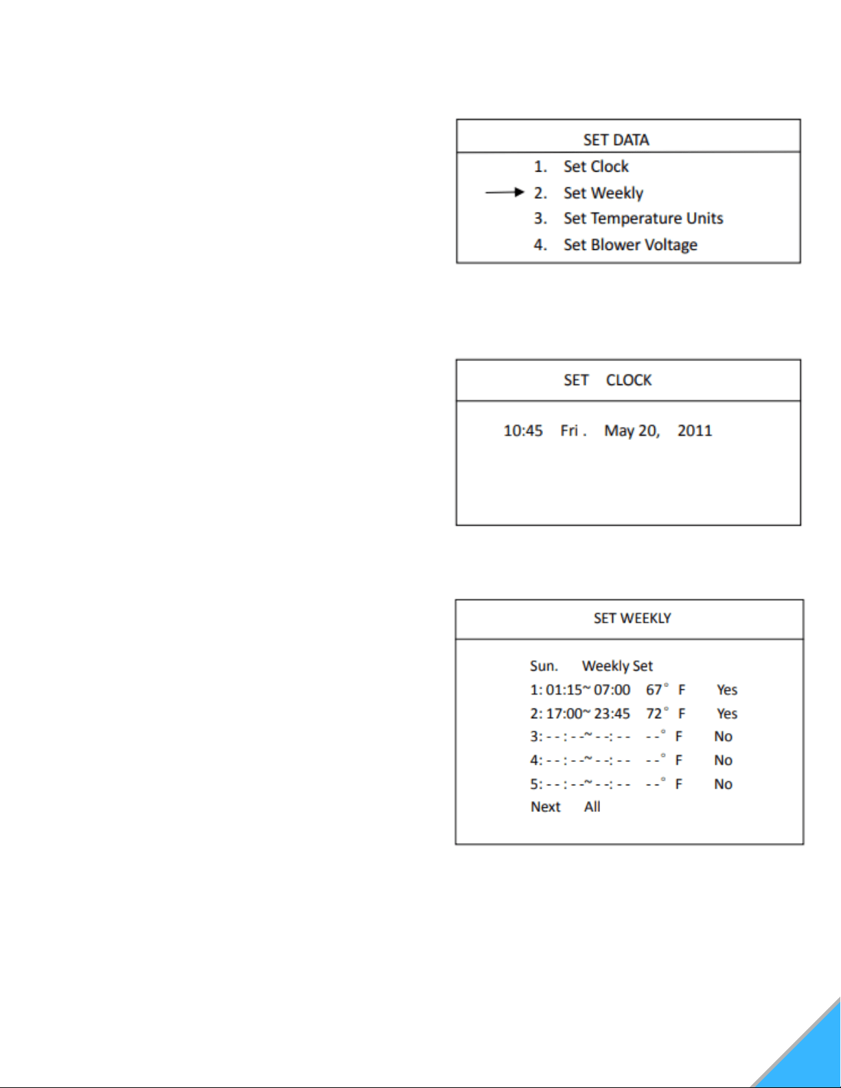
Press and hold the "Enter" button until the "set
data" menu appears on the screen. Using the
"Scroll Down" button, select "Set Weekly" and
press "Enter" This will take you into the weekly
schedule screen. See Figure 22
In the "Weekly Schedule" screen, you can begin
with setting the operation times for Sunday.
Press "Enter" to highlight the hour and use the
"Scroll Up and "Scroll Down" buttons until you
reach your desired hour of start time. Press
"Enter" again to highlight the minutes and use
the "Scroll Up" and "Scroll Down" until you
reach the desired minute of start. See Figure
24.
Pressing "Enter" again will allow you to set the
stop time of your stove. Use the same
procedure for setting your stove's start time for
selecting a stop time. Once you've selected the
stop time, press "Enter"
Next you will have the opportunity to set the
desired temperature. Use the "Scroll Up" or
"Scroll Down" keys until you've reached the
appropriate temperature for the times you have
selected. Press "Enter".
1.
2.
3.
4.
Figure 22: Set Data Menu
Figure 24: Set Weekly Menu
SETTING DATA ON YOUR CONTROLLER
SETTING THE TIME AND DATE
Press and hold the "Enter" button. This will take
you to the "Set Data" screen. See Figure 22
Press "Enter" again to enter the "Set Clock"
screen. See Figure 23
To change the hour, press "Enter". This will
highlight the hour block. Using "Scroll Up" and
"Scroll Down" select the correct time. Press
"Enter to select the correct hour, and then press
"Enter" a second time to begin setting the
minutes.
Continue this process for selecting and setting
the Day, Month, Date, and Year.
1.
2.
3.
4.
Figure 23: Set Clock Menu
SETTING WEEKLY SCHEDULE
NOTE: Your stove controller uses 24 hour
military time to set your weekly schedule.
27
7. Once you have set all times for the first day
(Sunday), "Scroll Down" to "Next" and press
"Enter" once. This will highlight "Next". Pressing
"Enter" again will progress to the following day.
Proceed with setting a schedule for the rest of
the week using the preceding instructions.
NOTE: Along with the "Next" option on the
screen, there is also an "All" option. After you
have set a particular time for a day, if you wish to
set that time for every day of the week, "Scroll
Down" to "Next" and press "Enter". Press "Scroll
Down" key to select and highlight "All". Press
"Enter" to select that scheduled time and apply it
to each day of the week.
8. Once you've finished setting your schedule,
without any of the options highlighted, press the
"Exit" button. This will save your schedule.
9. With a schedule set, make sure that the main
display screen on the controller reads "Weekly"
(for operating in the Weekly Mode) and that the
unit is turned on. The schedule will not take
effect unless the unit is turn ON and in the
Weekly Mode. (See #13 in Figure 19)
5. "Yes" will be highlighted. Pressing "Enter" will
confirm your selection and will take you out of
your first set time.
If you wish to erase a scheduled time, use the
"Enter" key to highlight "Yes" on the screen for
that scheduled time. Select "No" using the
"Scroll Up" or "Scroll Down" keys. While "No" is
highlighted, press "Enter" to erase the data.
6. To set another time for that particular day,
press "Scroll Down" and continue by repeating
steps 2-5 as desired.
NOTE: You must set your times in chronological
order. The first schedule slot of one day MUST
be earlier in the day than the second schedule
slot on your weekly schedule list, and so on.
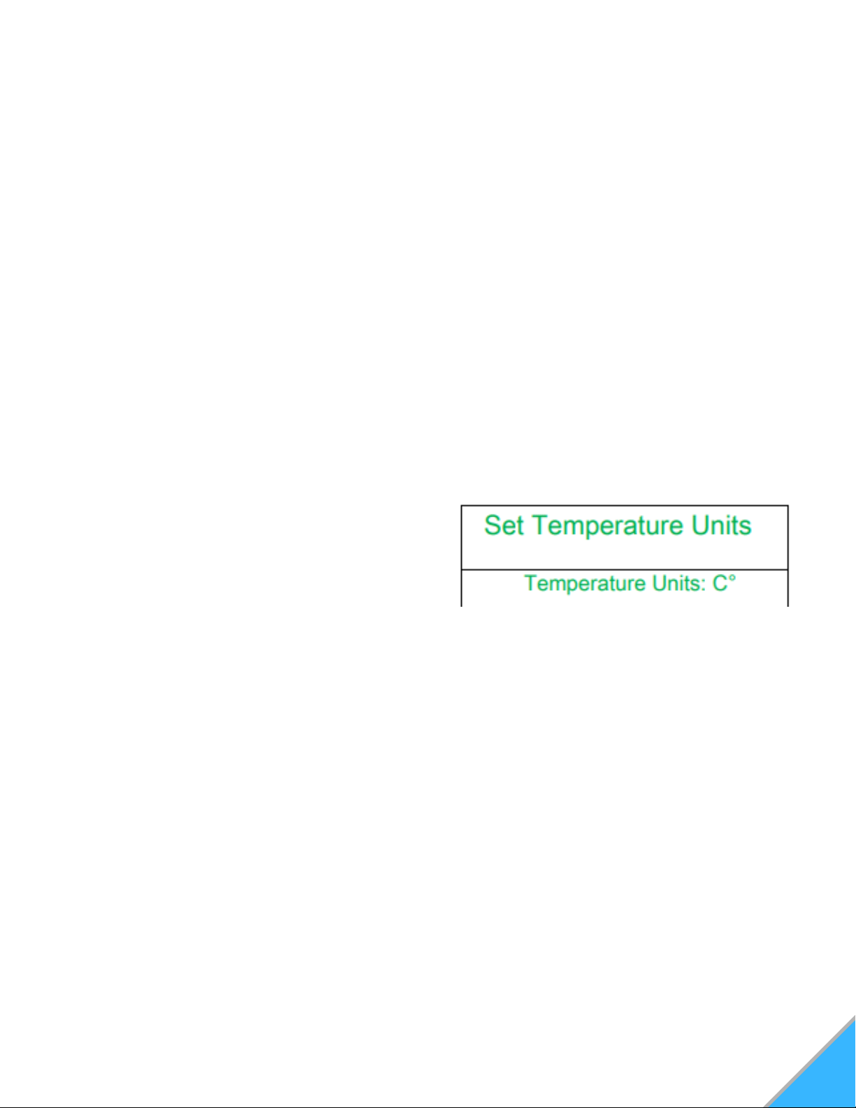
SETTING TEMPERATURE UNITS
Press and hold the "Enter" button. This will take
you to the "Set Data" screen.
Using the "Scroll Down" key, move down to
Option 3 "Set Temperature Units" and press
"Enter". This will take you into the "Set
Temperature Units" screen. See Figure 25
In the "Set Temperature Units" menu, press the
"Enter" key to highlight the units. Use "Scroll
Up" or "Scroll Down" to select either Celsius
(C°) or Fahrenheit (F°).
When finished, press "Enter". With nothing
highlighted on the screen, press the "Exit"
button.
1.
2.
3.
4.
Figure 25: Set Temperature Units Menu
TIP: If at any point, you need to leave the
weekly schedule screen or once you have
finished setting all of your times, select the
"Exit" button to return to the previous menu.
SETTING BLOWER VOLTAGE
The blower voltage (controlling the room blower or
convection fan) can be turned up or down for each
power level to regulate the amount of heat
circulated into the room during operation. Some
fuels radiate heat better than others. You have the
ability to speed up or slow down the room fan to
extract the optimum amount of heat without blowing
cold air. Increasing the blower voltage causes the
convection motor to run faster, extracting more heat
from the unit.
Decreasing the blower voltage allows you to slow
the exchange of heat from the stove so it blows
warmer air.
NOTE: If the stove is giving the over-temp alarm in
any setting, increasing the blower voltage may help.
28
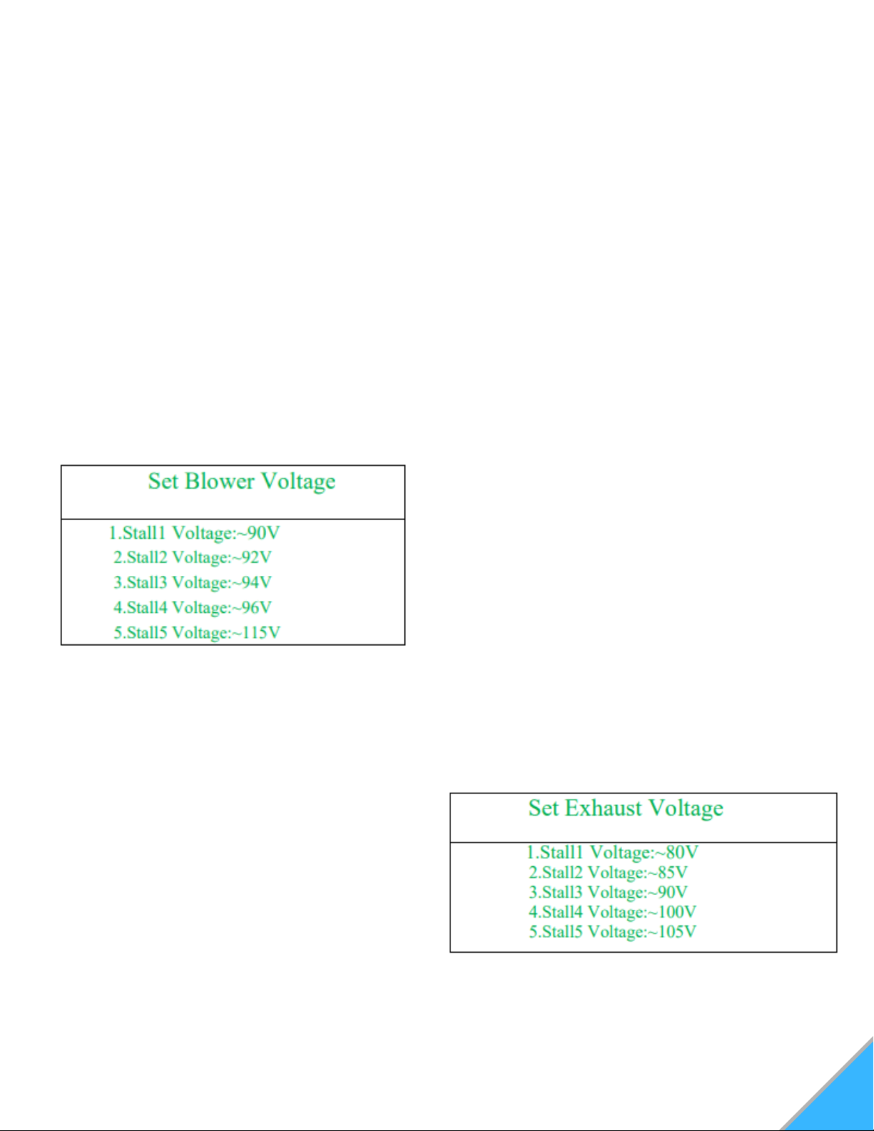
To Set Blower Voltage:
Press and hold the "Enter" button. This will take
you to the "Set Data" screen.
Using the "Scroll Down" key, move down to
option 4, "Set Blower Voltage". Press "Enter"
again to move into the "Set Blower Voltage"
screen. See Figure 26
Select the stall (or heating power level) for the
voltage you'd like to change by scrolling up or
down and pressing "Enter" The voltage amount
will automatically be highlighted.
Using the "Scroll Up" or "Scroll Down" keys,
select the appropriate voltage.
Press "Enter" to finalize your changes. Repeat
steps 2-4 for the other stalls that you wish to
change.
1.
2.
3.
4.
5.
Figure 26: Set Blower Voltage Menu
The exhaust voltage (controlling the combustion
motor) allows you to adjust the stove for the fuel
you are burning or compensate for
inadequate ventilation situations. In less than
optimal venting situations, you can increase the
exhaust speed for additional air circulation through
the stove.
SETTING EXHAUST VOLTAGE
To Set Exhaust Voltage:
Press and hold the "Enter" button. This will take
you to the "Set Data" screen.
Using the "Scroll Down" key, move down to
option 5, "Set Exhaust Voltage". Press "Enter"
again to move into the "Set Exhaust Voltage"
screen. See Figure 27
Select the stall (or heating power level) for the
voltage you'd like to change by scrolling up or
down and pressing "Enter" The voltage amount
will automatically be highlighted.
Using the "Scroll Up" or "Scroll Down" keys,
select the appropriate voltage.
Press "Enter" to finalize your changes. Repeat
steps 2-4 for the other stalls that you wish to
change.
1.
2.
3.
4.
5.
Figure 27: Set Exhaust Voltage Menu
IMPORTANT: Changing the exhaust voltage does
NOT change the feed rate. Therefore, on high heat
power levels, where the feed rate is faster, a low
voltage level will not push out enough air and the
stove may overheat and/or pellets may back up into
the burn pot. Decreasing exhaust voltages will
increase the amount of heat coming into the room.
Do not adjust the exhaust voltage too low, as it can
cause pellets to back up in the burn pot.
Increasing the exhaust voltage, and thereby
increasing the amount of airflow through the burn
pot, will also assist in burning lower quality fuels
that may otherwise cause unwanted buildup.
NOTE: Be sure to visually watch the burn rate if the
exhaust voltage is decreased, as to not cause pot
overloading. Exhaust voltage should ONLY be
adjusted to get the optimum performance out of the
fuel you are using.

29
DIAGNOSTICS
Your stove's controller comes equipped with an
on-board diagnostics option that will let you test
some components of the stove.
NOTE: You will only be able to enter the
diagnostic screen when the stove is turned
OFF.
To get into the diagnostic screen:
Press and hold the "Enter" button. This will
take you to the "Set Data" screen.
Using the "Scroll Down" key, move to option 6
"Diagnostics". Press "Enter" to access the
"Diagnostics Screen" See Figure 28
1.
2.
Figure 28: Diagnostics Menu
NOTE: The shaded circles indicate when a
component is in the "Engaged" or ON
position.
When stove is OFF and cool, the only circle
that will appear shaded is the "Limit" (Hopper
Lid Indicator)
In the diagnostics mode, you will have the ability
to test certain components of the stove to ensure
they are working as intended.
In order to test a specific component:
Move the cursor arrow to the desired
component keyword using the "Scroll Up" or
"Scroll Down" keys, and press "Enter"
The selected component keyword will
highlight. Press the "Scroll Up" or "Scroll
Down" key once to shade the selected circle.
This will turn on, or "Engage" this component.
The only components that you are able to
manually Engage are "Fire", "Blower", "Exhaust",
and "Feeding"
1.
2.
Component Keywords:
Stalls: Changing the stall # will allow you to test
the components in the various heating power
levels.
Fire: Tests whether the igniter is working
properly.
Exhaust: Tests whether the combustion motor
and exhaust system is working properly.
Limit: Will indicate whether the hopper lid is
properly shut.
Blower: Tests whether the room blower fan is
working properly.
Feeding: Tests whether the auger is properly
feeding pellets.
Vacuum: Will indicate whether there is sufficient
negative pressure in the stove. (Should shade
when "Exhaust" is engaged).
NTC1: Proof of Fire indicator. (Will only be
shaded when stove is still hot enough to engage
the P.O.F. switch.
NTC2: Will indicate temperature being read by
the overheat sensor. (Temperature is in Celsius)
1.
2.
3.
4.
5.
6.
7.
8.
9.
Option 9 "Restore Default Settings" should never
need to be used, as the correct baseline settings
are programmed into the controller during the
inspection process.
NOTE: Restoring default settings will erase the
changes that were made during the inspection
process and could affect the performance of your
stove.
RESTORING DEFAULT SETTINGS
Press the "On/Off" button on the control pad to
initiate the shut down mode. The On/Off indicator on
the screen will now read "Off".
The auger will stop feeding pellets, but the exhaust
fan and room blower fans will continue to operate for
a time. Once the stove has cooled, the screen light
will turn off.
NOTE: Stove shut down times can vary.
SHUT DOWN PROCEDURE
30
NORMAL CARE AND MAINTENANCE
A majority of all problems with pellet stoves are
either directly or indirectly related to general
maintenance and cleaning issues. Regularly
cleaning your stove will allow it to function
properly and extends the life of most of the stove’s
components.
Due to differences in fuel quality, stove cleaning
intervals can vary wildly. However, the cleaner the
stove is, the more efficiently it will burn.
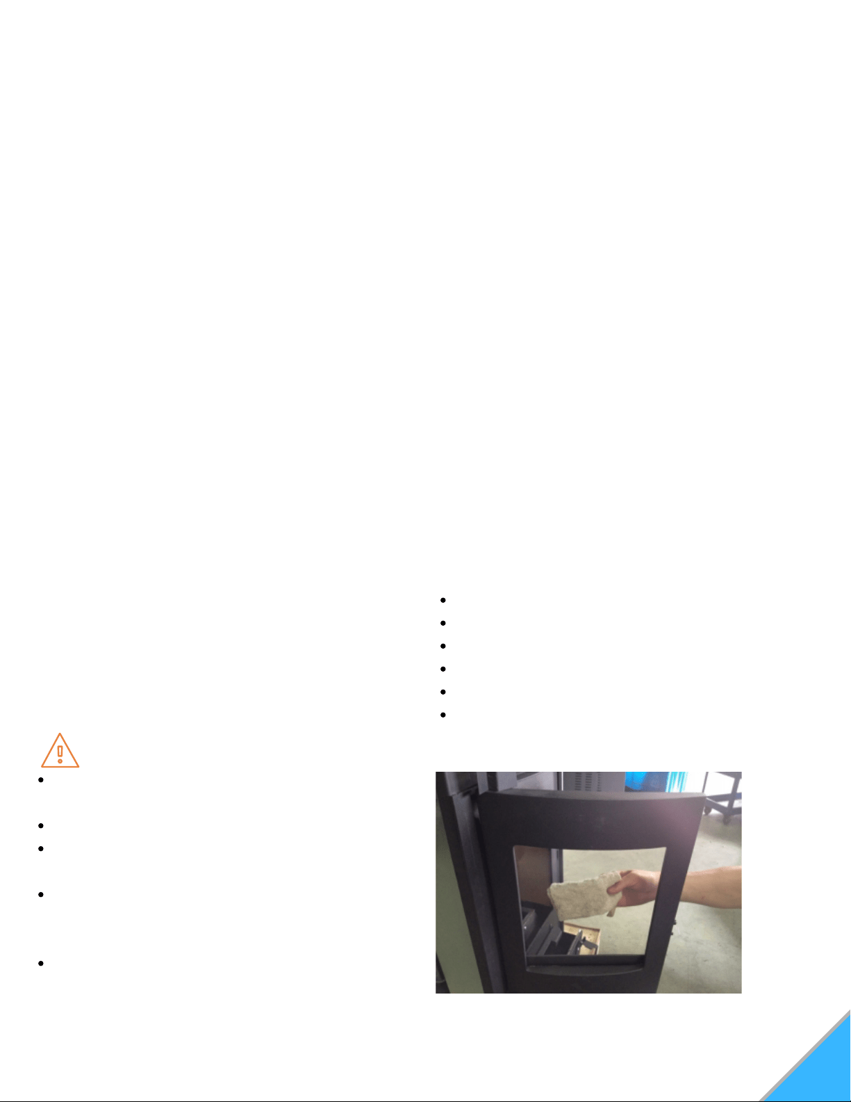
GLASS FRONT DOOR
Only clean the glass when the glass is cool. Wipe
the glass clean with a dry or damp rag. If this
does not remove all build-up, use of any non-
abrasive cleaner is approved. Using ceramic
stove top cleaner can be helpful in removing soot
build-up from the glass. See Figure 29
Inspect the gaskets around the door periodically
and replace any worn, frayed or compacted
gaskets.
NOTE: Only replace broken glass with high
temperature ceramic glass.
Figure 29: Front Door Glass
MAINTENANCE
SOOT AND FLY ASH
The products of combustion will contain small
particles of fly ash. The fly ash will collect in the
exhaust venting system and restrict the flow of the
flue gasses. Incomplete combustion, which
occurs during startup and shutdown, or incorrect
operation of the stove, will lead to some soot
formation collecting in the exhaust venting
system. The exhaust venting system should be
inspected regularly to determine if cleaning is
necessary. If cleaning is necessary, disassemble
the exhaust vent and clean the individual parts.
When cleaning ash, use an approved ash
vacuum.
Clean out T-vents regularly to determine the
required cleaning interval. Use a 3" or 4" chimney
brush to clean exhaust venting. Plugged venting
will effect the quality of the fire. Make sure to
clean any screens in the venting regularly as a
plugged screen can restrict combustion air and
cause the fire to burn poorly.
WARNING
Never perform cleaning or maintenance on a
hot stove.
Allow unit to cool for a minimum of two hours.
Never perform service with power supplied to
the unit.
Interior components may still be hot, even
when stove surfaces are cool to the touch. A
protective glove is recommended.
Clinkers may remain hot for several minutes
after they are pulled from the burn pot.
CAUTION
Do Not operate stove with broken glass
Do Not slam doors shut.
Do Not strike the glass.
Do Not use abrasive cleaners.
Do Not clean hot glass.
Replace ceramic glass with factory authorized
replacement parts only.
31
DAILY MAINTENANCE
BURN POT
Remove and clean the burn pot daily. Make sure all
of the airflow holes in the burn pot are
unobstructed. Using a small metal pick or drill bit
can aid you if these get plugged through general
use. Every time the hopper is filled with fuel, the
burn pot should be emptied.
In order to empty the burn pot, lift it out of the cradle and
dump it directly into the ash pan. Be sure any build-up is
removed when clearing the airflow holes. See Figure 30
ASH PAN
Empty the ash pan regularly. Ashes should be
contained in a metal container with a tight fitting lid.
The container of ashes should be placed on
a noncombustible floor or, well away from any
combustible materials. If ashes are disposed of by
burial, or otherwise dispersed, they should remain
inside the enclosed container until all cinders have
cooled. The frequency in which the ash pan will
need emptied will vary depending on the amount of
fuel burned. See Figure 31
INTERIOR CHAMBER
In addition to the daily maintenance tasks, clean
the interior chamber with an ash vacuum. (Ash
vacuums have a metal canister that is specially
designed to contain soot).
Remove the burn pot from the cradle and vacuum
beneath. Be sure to remove any ash buildup in and
around the igniter tube. See Figure 32
NOTE: When cleaning/vacuuming out the
igniter tube, ensure that the igniter rod does not
get pushed out of position.
Figure 31: Ash Pan
Figure 30: Burn Pot
WEEKLY MAINTENANCE
Figure 32: Burn Pot Cradle/Igniter Tube
32
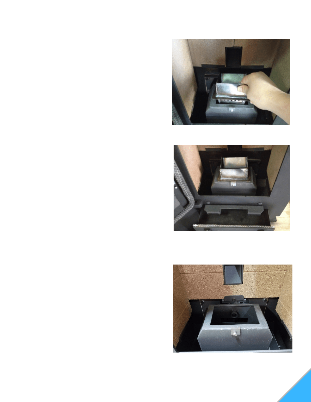
CONTINUING MAINTENANCE
In addition to daily and weekly maintenance tasks, the
exhaust chamber covers should be removed and the
entire chamber vacuumed thoroughly once every 1.5
tons of pellets burned.
First, you will need to locate the cover plates to the
rear exhaust chambers. These chamber covers are
small, rectangular, metal plates that are affixed with 2
wing nuts.There are two total chamber covers, one on
each side of the firebox near the bottom, accessed
vie the removeable side panels.
See Figure 33A and 33B
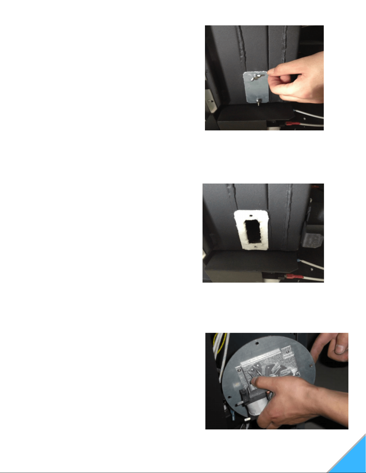
Once you have located the chamber covers, you will
then remove them by unscrewing the wing nuts and
pulling the plate back. There is a gasket behind the
plate to help make an airtight seal so the stove does
not draw in air through these panels. It is ok to cut
through the center of the gasket to access the
chamber behind it. As long as there is adequate
gasket material around the perimeter, it will provide a
proper seal. Using a slender hose attachment on your
ash vac, thoroughly vacuum out these chambers top
to bottom. These chambers extend all the way up to
the heat exchange tubes near the top of the stove, so
it is imperative that the entire chamber is cleaned, top
to bottom. Using a cross-hatching/sweeping motion
will ensure that no area is neglected and as much of
the ash and debris is removed as possible.
REAR AIRFLOW/EXHAUST CHAMBER
Figure 33A: Exhaust Chamber Cover Plate.
Figure 33B: Exhaust Chamber Cover Plate.
removed.
EXHAUST & COMBUSTION ASSEMBLY
In addition to the daily and weekly maintenance
tasks, the exhaust venting, and combustion motor,
housing, and impellers should be inspected and
cleaned once per year. See Figure 34
There is a combustion motor gasket, which allows
you to remove the motor from the housing, for
inspection and cleaning, without having to remove
the entire exhaust fan. However, if you must remove
or replace the entire exhaust fan, a new blower
flange gasket should be added between the blower
flange and the steel plate.
Figure 34: Combustion Motor Assembly

TROUBLESHOOTING & REPAIR
We build quality and durability into the design of our products; but no amount of careful design by us,
and careful maintenance by you, can guarantee a repair free life for your stove. Most repairs will be
minor, and easily fixed by following the suggestions in the troubleshooting guides on our website. The
guides will help you pinpoint the causes of common problems and identify remedies. For more
complicated repairs, you may want to rely on your retailer. Troubleshooting & Component Guides can
be found on our website, as well as YouTube videos. We will always be glad to answer any questions
you may have, or help you find suitable assistance.
WARRANTY
This warranty is non-transferable and is made to the original retail purchaser only, provided that the
purchase was made through an authorized ComfortBilt dealer. It must be installed and operated in
accordance with the Installation and Operating Instructions furnished with this product, as well as any
applicable local and national codes. Any alteration, willful abuse, accident, or misuse of the product
shall nullify this warranty.
SMG Hearth and Home LLC, a Manufacturing Company warrants this HP22 to be free from defects in
the material or workmanship for a period of one year. During that one-year period, SMG will, at their
discretion, furnish parts and labor to correct any defect caust by the faulty material or workmanship.
For other warranty repairs, please read the One-Year Warranty listed below.
ONE-YEAR WARRANTY
All electrical components such as, but not limited to, blowers, wiring, safety switches, controllers,
igniters, and circuit boards are covered under SMG Hearth and Home LLC's One-Year Warranty.
Burn pots, and labor are also covered under the One-Year Warranty.
This warranty is limited to defective parts repair and/or replacement at SMG hearth and Home LLC's
option, and excludes any incidental and consequential damages connected therein.
The warranty is not transferable and supersedes all other warranties either expressed or implied, and
all other obligations to liabilities on our part. SMG Heath and Home LLC does not assume, and does
not authorize any other person to assume for us, any liability in connection with the sale of our
products. The warranty applies only to products which have not been subjected to negligent use,
misuse, alteration, accident, or repairs made by anyone not certified by SMG Hearth and Home LLC.
This guarantee is void unless the warranty card is properly filled out and returned to SMG Hearth and
Home LLC, or completed online, at the time of purchase.
SMG Hearth and Home LLC
9241 Globe Center Dr. Suite 120
Morrisville, NC 27560
919-973-4092
www.comfortbilt.net
*Technical service calls are answered
Monday thru Friday, 9am-5pm eastern time.
33