
THANK YOU for purchasing this high-quality product. If you should experience a problem not covered in TROUBLESHOOTING or
PROBLEM SOLVER, please visit our website at www.whirlpool.com for additional information. If you still need assistance, call us
at 1-800-253-1301. In Canada, visit our website at www.whirlpool.ca or call us at 1-800-807-6777.
You will need your model and serial number, located on the inside wall of the refrigerator compartment.
Table of Contents / Índice / Table des matières
REFRIGERATOR SAFETY ................................2
Proper Disposal of Your Old Refrigerator......3
REFRIGERATOR USE.......................................3
Install Air Filter ................................................3
Install Produce Preserver ...............................4
Using the Controls..........................................5
Convertible Drawer Temperature Control......6
Crisper Humidity Control................................6
Chilled Door Bin..............................................6
Water and Ice Dispensers ..............................6
Ice Maker and Storage Bin.............................8
Water Filtration System ..................................9
REFRIGERATOR CARE....................................9
Cleaning..........................................................9
Lights ............................................................10
Vacation and Moving Care...........................10
PROBLEM SOLVER........................................11
ACCESSORIES................................................15
WATER FILTER CERTIFICATIONS................15
PERFORMANCE DATA SHEET .....................16
WARRANTY.....................................................17
SEGURIDAD DEL REFRIGERADOR..............19
Cómo deshacerse adecuadamente
de su refrigerador viejo.................................20
USO DE SU REFRIGERADOR........................20
Instalación del filtro de aire ..........................20
Instalación del preservador
de alimentos frescos ....................................21
Uso de los controles.....................................22
Control de temperatura
del cajón convertible ....................................23
Control de humedad del
cajón para verduras......................................24
Depósito enfriador de la puerta....................24
Despachadores de agua y hielo...................24
Fábrica de hielo y depósito..........................25
Sistema de filtración de agua.......................27
CUIDADO DE SU REFRIGERADOR ..............27
Limpieza........................................................27
Luces ............................................................28
Cuidado durante las
vacaciones y mudanzas...............................28
SOLUCIÓN DE PROBLEMAS ........................29
ACCESORIOS..................................................34
HOJA DE DATOS DEL RENDIMIENTO.........35
GARANTÍA .......................................................36
SÉCURITÉ DU RÉFRIGÉRATEUR.................38
Mise au rebut appropriée
de votre vieux réfrigérateur ..........................39
UTILISATION DU RÉFRIGÉRATEUR.............39
Installation du filtre à air................................39
Installation du sachet de conservation
pour produits frais ........................................40
Utilisation des commandes..........................41
Commande de température dans
le tiroir convertible ........................................43
Réglage de l'humidité
dans le bac à légumes .................................43
Compartiment fraîcheur dans la porte.........43
Distributeurs d’eau et de glaçons ................43
Machine à glaçons et bac d'entreposage....45
Système de filtration de l'eau.......................46
ENTRETIEN DU RÉFRIGÉRATEUR...............46
Nettoyage .....................................................46
Lampes.........................................................47
Entretien avant les vacances ou
lors d’un déménagement .............................47
RÉSOLUTION DE PROBLÈMES....................48
ACCESSOIRES................................................53
FEUILLE DE DONNÉES
SUR LA PERFORMANCE...............................54
GARANTIE .......................................................55
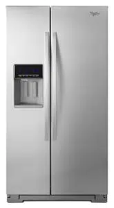
REFRIGERATOR
USER INSTRUCTIONS
W10571759A
2
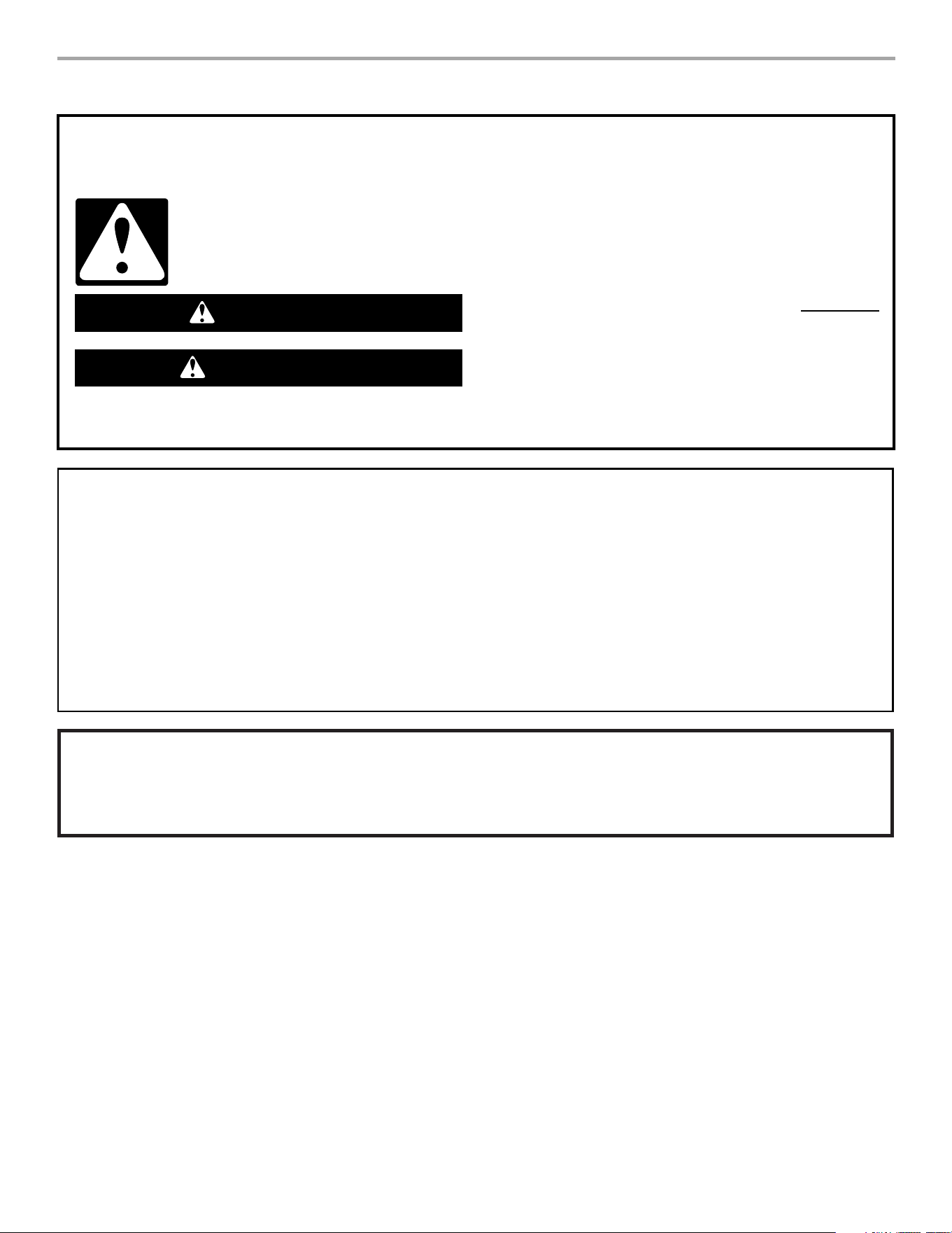
REFRIGERATOR SAFETY
You can be killed or seriously injured if you don't immediately
You
can be killed or seriously injured if you don't
follow
All safety messages will tell you what the potential hazard is, tell you how to reduce the chance of injury, and tell you what can
happen if the instructions are not followed.
Your safety and the safety of others are very important.
We have provided many important safety messages in this manual and on your appliance. Always read and obey all safety
messages.
This is the safety alert symbol.
This symbol alerts you to potential hazards that can kill or hurt you and others.
All safety messages will follow the safety alert symbol and either the word “DANGER” or “WARNING.”
These words mean:
follow instructions.
instructions.
DANGER
WARNING
IMPORTANT SAFETY INSTRUCTIONS
WARNING:
To reduce the risk of fire, electric shock, or injury when using your refrigerator, follow these basic precautions:
SAVE THESE INSTRUCTIONS
■ Plug into a grounded 3 prong outlet.
■ Do not remove ground prong.
■ Do not use an adapter.
■ Do not use an extension cord.
■ Disconnect power before servicing.
■ Replace all parts and panels before operating.
■ Remove doors from your old refrigerator.
■ Use nonflammable cleaner.
■ Keep flammable materials and vapors, such as gasoline,
away from refrigerator.
■ Use two or more people to move and install refrigerator.
■ Disconnect power before installing ice maker (on ice maker
kit ready models only).
■ Use a sturdy glass when dispensing ice (on some models).
■ Do not hit the refrigerator glass doors (on some models).
State of California Proposition 65 Warnings:
WARNING: This product contains one or more chemicals known to the State of California to cause cancer.
WARNING: This product contains one or more chemicals known to the State of California to cause birth defects or other
reproductive harm.
3
Proper Disposal of
Your Old Refrigerator
IMPORTANT: Child entrapment and suffocation are not problems
of the past. Junked or abandoned refrigerators are still dangerous,
even if they will sit for “just a few days.” If you are getting rid of
your old refrigerator, please follow these instructions to help
prevent accidents.
Before You Throw Away Your Old Refrigerator or Freezer:
■ Take off the doors.
■ Leave the shelves in place so that children may not easily
climb inside.
REFRIGERATOR USE
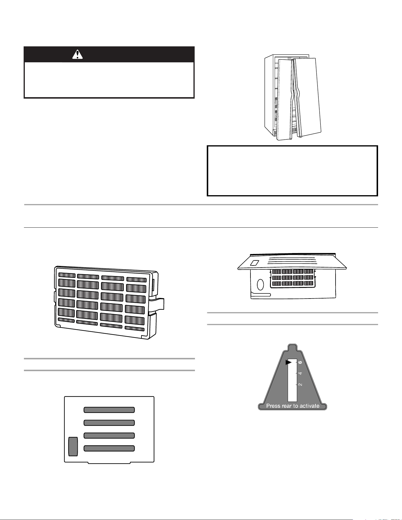
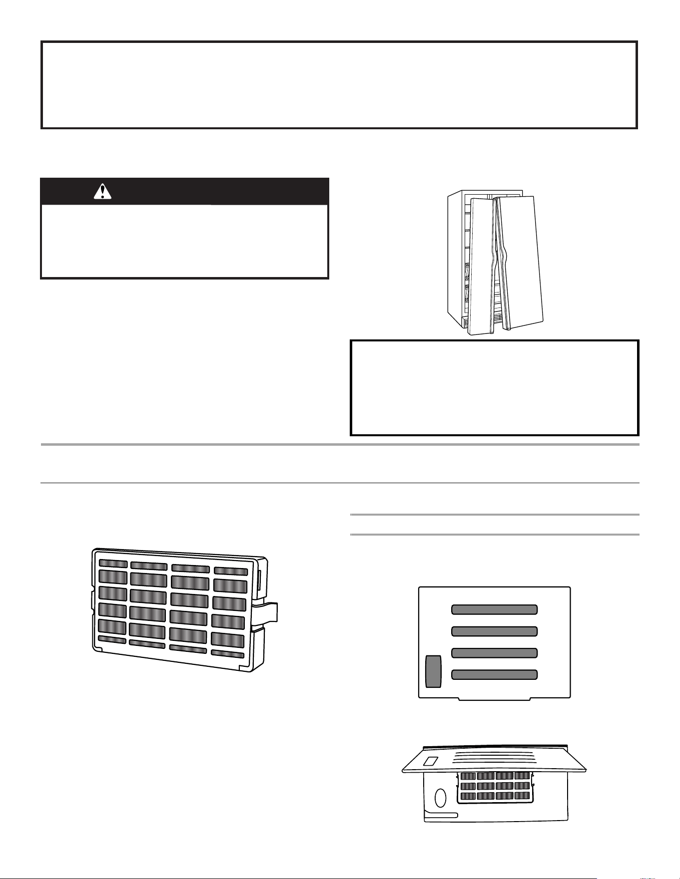
Install Air Filter (on some models)
On some models, your refrigerator's accessory packet includes
an air filter, which must be installed prior to use. On some models,
the air filter is already installed at the factory.
The air filter reduces the buildup of odors. This helps to maintain a
cleaner environment inside the refrigerator.
Installing the Air Filter (on some models)
The filter should be installed behind the vented door, which is
located (depending on your model) along either the rear or left
interior wall near the top of the refrigerator compartment.
1. Remove the air filter from its packaging.
2. Lift open the vented door.
3. Snap the filter into place.
4. Close the vented door.
Installing the Filter Status Indicator (on some models)
The filter comes with a status indicator, which should be activated
and installed at the same time the air filter is installed.
1. Place the indicator face-down on a firm, flat surface.
2. Apply pressure to the bubble on the back of the indicator, until
the bubble pops to activate the indicator.
3. Lift open the vented air filter door. On some models, there are
notches behind the door.
4. On models with notches:
■ Slide the indicator down into the notches, facing outward.
NOTE: The indicator will not easily slide into the notches
if the rear bubble has not been popped.
■ Close the air filter door, and check that the indicator is
visible through the rectangular hole in the door.
WARNING
Suffocation Hazard
Remove doors from your old refrigerator.
Failure to do so can result in death or brain damage.
Important information to know about disposal of
refrigerants:
Dispose of refrigerator in accordance with Federal and Local
regulations. Refrigerants must be evacuated by a licensed,
EPA certified refrigerant technician in accordance with
established procedures.
MONTHS
REPLACE
4
On models without notches:
■ Store the indicator in a visible place you will easily
remember - either inside the refrigerator, or elsewhere in
your kitchen or home.
Replacing the Air Filter
The disposable air filter should be replaced every 6 months, when
the status indicator has completely changed from white to red.
To order a replacement air filter, see “Accessories.”
1. Remove the old air filter by squeezing in on the side tabs.
2. Remove the old status indicator.
3. Install the new air filter and status indicator using the
instructions in the previous sections.
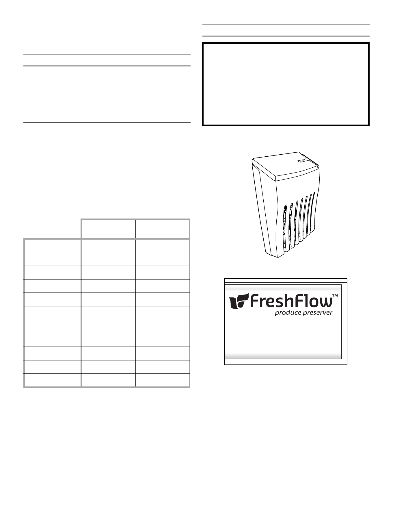
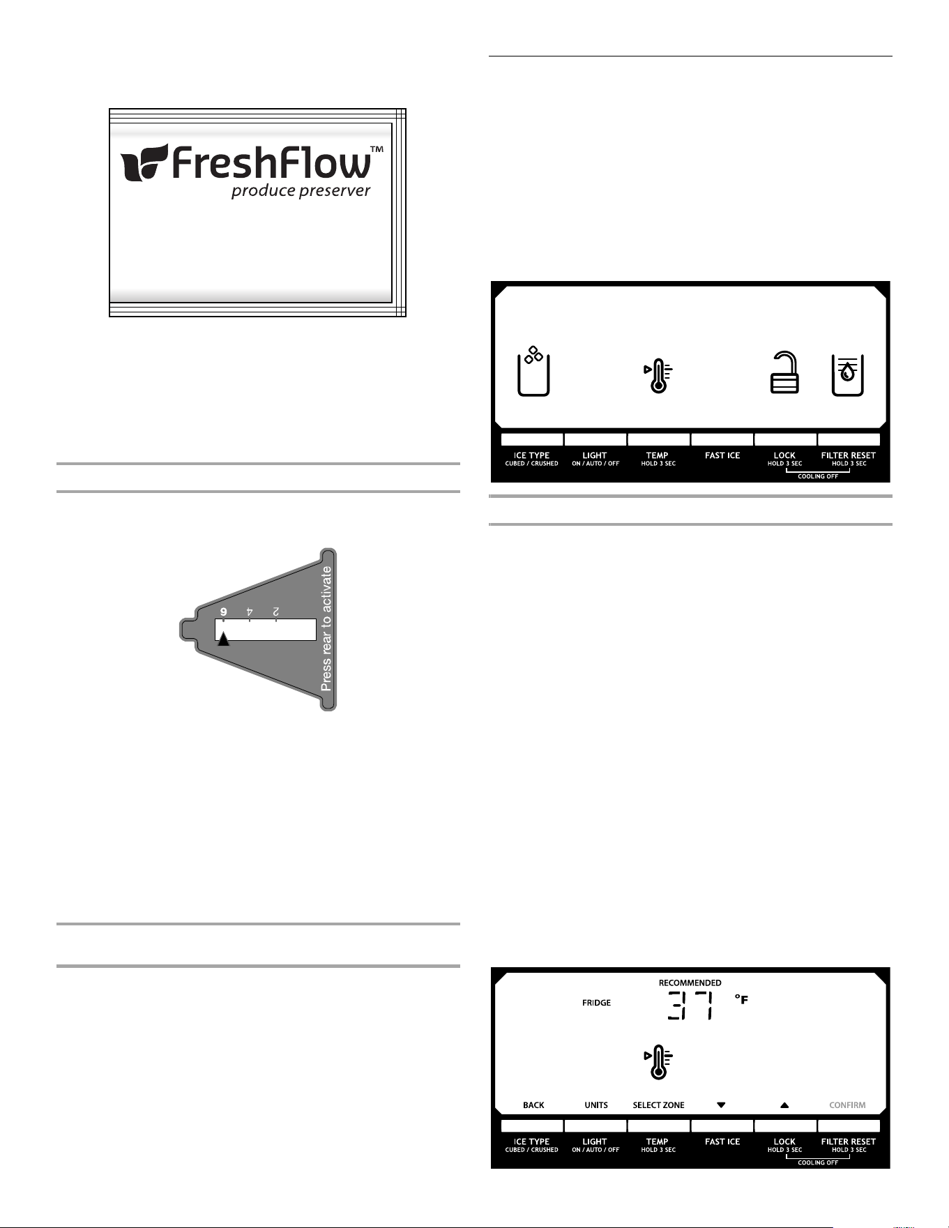
Install Produce Preserver
(on some models)
On some models, your refrigerator's accessory packet includes a
Produce Preserver, which should be installed prior to use. On
some models, the Produce Preserver is already installed at the
factory.
The Produce Preserver absorbs ethylene, allowing the ripening
process of many produce items to slow down. As a result, certain
produce items will stay fresh longer.
Ethylene production and sensitivity varies depending on the type
of fruit or vegetable. To preserve freshness, it is best to separate
produce with sensitivity to ethylene from fruits that produce
moderate to high amounts of ethylene.
Installing the Produce Preserver (on some models)
The Produce Preserver pouches should be installed in their
housing, which is located along an interior side wall of the crisper
or convertible drawer.
NOTE: For best performance, always use two pouches.
1. Remove the Produce Preserver pouches from their packaging.
2. Lift up on the housing in order to remove it from its mounting
tab along the wall.
3. Open the housing by pulling up and out on the back of the top
of the housing.
4. Place both pouches inside the housing, then snap the housing
back together.
5. Place the housing back on the mounting tab along the wall.
Sensitivity to
Ethylene
Ethylene
Production
Apples High Very High
Asparagus Med. Very Low
Berries Low Low
Broccoli High Very Low
Cantaloupe Med. High
Carrots Low Very Low
Citrus Fruit Med. Very Low
Grapes Low Very Low
Lettuce High Very Low
Pears High Very High
Spinach High Very Low
CAUTION: IRRITANT
MAY IRRITATE EYES AND SKIN. DANGEROUS FUMES
FORM WHEN MIXED WITH OTHER PRODUCTS.
Do not mix with cleaning products containing ammonia,
bleach or acids. Do not get in eyes, on skin or clothing. Do
not breathe dust. Keep out of reach of children.
FIRST AID TREATMENT: Contains potassium
permanganate. If swallowed, call a Poison Control Center or
doctor immediately. Do not induce vomiting. If in eyes, rinse
with water for 15 minutes. If on skin, rinse with water.
CAUTION
IR
R
ITA
N
T
Read cautions on back.
ATTENTION
IR
R
ITA
N
T
Lisez des prudences sur le revers.
CAUTION
IRRITANT
Read cautions on back.
ATTENTION
IRRITANT
Lire les mises en garde au dos.
Whirlpool Corporation, Benton Harbor MI 49022
5
Installing the Status Indicator (on some models)
The Produce Preserver comes with a status indicator, which
should be activated and installed at the same time the pouch is
installed.
1. Place the indicator face-down on a firm, flat surface.
2. Apply pressure to the bubble on the back of the indicator, until
the bubble pops to activate the indicator.
3. Slide open the cap on the Produce Preserver housing.
4. Place the indicator in the top of the housing, facing outward.
5. Slide the cap closed, and check that the indicator is visible
through the rectangular hole in the cap.
NOTE: The cap will not easily close if the indicator’s rear
bubble has not been popped.
Replacing the Produce Preserver (on some models)
The disposable pouches should be replaced every 6 months,
when the status indicator has completely changed from white to
red.
To order replacements, see “Accessories.”
1. Remove the old pouches from the Produce Preserver housing.
2. Remove the old status indicator.
3. Install the new pouches and status indicator using the
instructions in the previous sections.
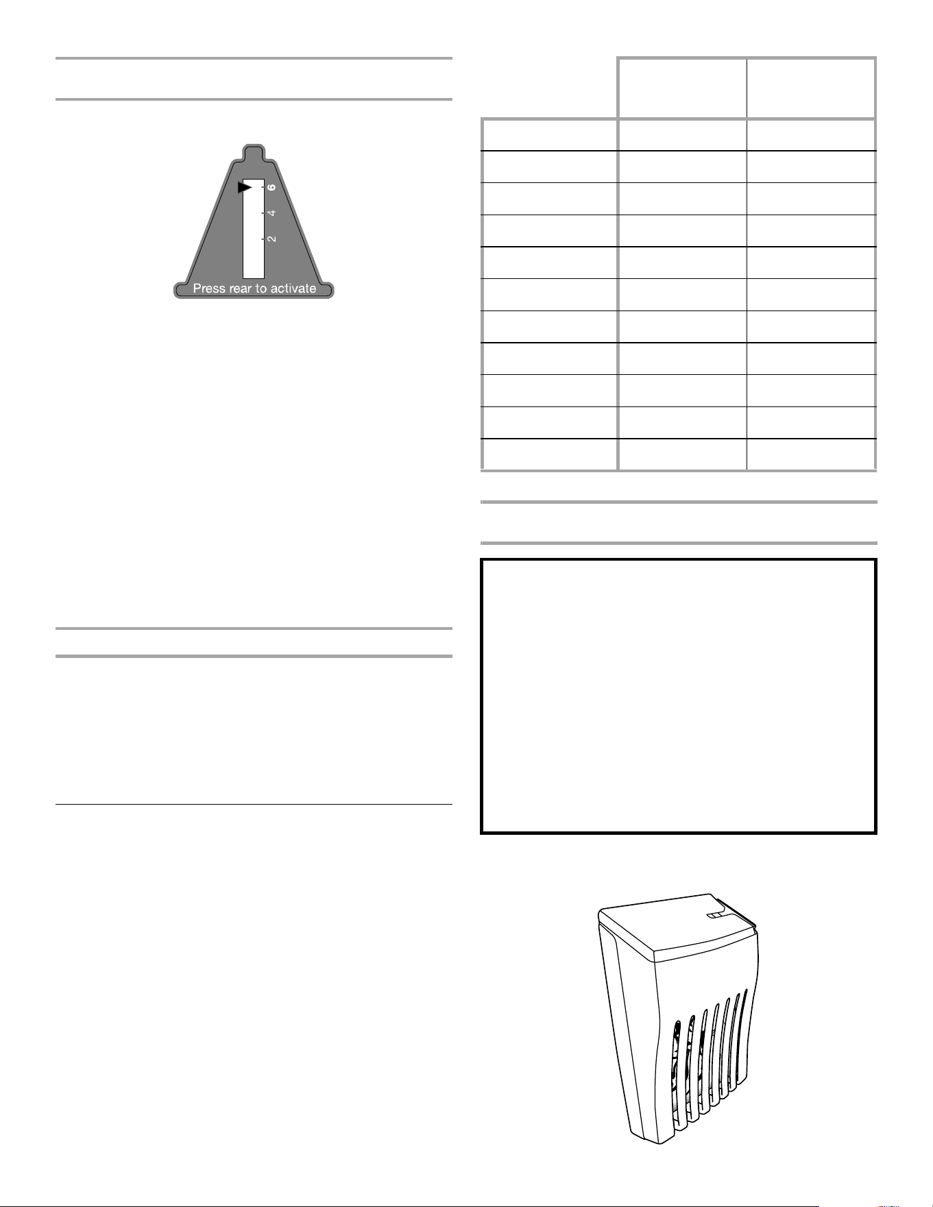
Using the Controls
The refrigerator and freezer controls are located on the dispenser
panel.
IMPORTANT: The display screen on the dispenser control panel
will turn off automatically and enter “sleep” mode when the
control buttons and dispenser pads have not been used for
2 minutes or more. While in “sleep” mode, the first press of a
control button will only reactivate the display screen, without
changing any settings.
■ Touch any control button on the dispenser panel to activate
the display screen. The home screen will appear as shown.
Adjusting the Controls
For your convenience, your refrigerator and freezer controls are
preset at the factory. When you first install your refrigerator, make
sure that the controls are still set to the “mid-settings.” The factory
recommended set points are 37°F (3°C) for the refrigerator and
0°F (-18°C) for the freezer.
IMPORTANT:
■ Wait 24 hours before you put food into the refrigerator. If you
add food before the refrigerator has cooled completely, your
food may spoil.
NOTE: Adjusting the set points to a colder than
recommended setting will not cool the compartments any
faster.
■ If the temperature is too warm or too cold in the refrigerator or
freezer, first check the air vents to be sure they are not
blocked before adjusting the controls.
■ The preset settings should be correct for normal household
usage. The controls are set correctly when milk or juice is as
cold as you like and when ice cream is firm.
■ Wait at least 24 hours between adjustments. Recheck the
temperatures before other adjustments are made.
To view and adjust the set points, press and hold the TEMP
button for 3 seconds. When adjust mode is activated, adjusting
information will appear on the display screen.
NOTE: To view Celsius temperatures, press the LIGHT button
when adjust mode is activated. To return the display setting to
Fahrenheit, press LIGHT again.
■ When adjust mode is activated, the display screen shows the
refrigerator set point and “FRIDGE” appears.
■ Press LOCK to raise the set point, or press FAST ICE to lower
the set point.
■ When you have finished viewing (and adjusting if desired) the
refrigerator set point, press TEMP to change the display to
show the freezer set point. When the zone has been changed,
“FREEZER” appears on the display screen.
■ Press LOCK to raise the set point, or press FAST ICE to lower
the set point.
■ When you have finished viewing (and adjusting if desired) both
the refrigerator and freezer set points, press FILTER to save
the settings.
NOTE: To exit without saving changes, press ICE TYPE at any
time while in adjust mode, or allow about 60 seconds of
inactivity and adjust mode will turn off automatically.
When adjusting temperature set points, use the following chart as
a guide.
The set point range for the refrigerator is 33°F to 45°F (0°C to
7°C). The set point range for the freezer is -5°F to 5°F (-21°C to
-15°C).
MONTHS
REPLACE
CONDITION: TEMPERATURE
ADJUSTMENT:
REFRIGERATOR too cold REFRIGERATOR Setting
1° higher
REFRIGERATOR too warm REFRIGERATOR Setting
1° lower
FREEZER too cold FREEZER Setting 1° higher
FREEZER too warm /
Too little ice
FREEZER Setting 1° lower
6
Cooling On/Off
Your refrigerator and freezer will not cool when cooling is
turned off.
■ To turn cooling off, press and hold the LOCK and FILTER
buttons at the same time for 3 seconds.
IMPORTANT: To avoid unintentionally locking the dispenser
or changing other settings, be sure to press both buttons at
exactly the same time.
When cooling is off, “COOLING OFF” will appear on the
display screen.
■ Press and hold LOCK and FILTER for 3 seconds again to turn
cooling back on.
Additional Features
Fast Ice
The Fast Ice feature assists with temporary periods of heavy ice
use by increasing ice production over a 24-hour period.
IMPORTANT: This feature only works if the ice maker is turned
on. See “Ice Maker and Storage Bin.”
■ Press FAST ICE to turn on the Fast Ice feature. When the
feature is on, the Fast Ice icon will appear on the dispenser
display screen. The Fast Ice setting will remain on for 24 hours
unless manually turned off.
■ To manually turn off the Fast Ice feature, press FAST ICE again
or adjust the freezer temperature set point. The Fast Ice icon
will disappear when the feature is off.
NOTE: If increased ice production is desired at all times, change
the freezer set point to a lower setting. Setting the freezer to a
colder temperature may make some foods, such as ice cream,
harder.
Door Ajar Alarm
The Door Ajar Alarm feature sounds an alarm when the refrigerator
or freezer door is open for 5 minutes and the product cooling is
turned on. The alarm will repeat every 2 minutes. Close both
doors to turn it off. The feature then resets and will reactivate
when either door is left open again for 5 minutes.
NOTE: To mute the audible alarm while keeping the doors open,
such as while cleaning the inside of the refrigerator, press any
button on the control panel. The alarm sound will be temporarily
turned off, but the Door Ajar icon will still be displayed on the
dispenser control panel.
Dual Evaporator (on some models)
Some models come equipped with a dual sequential evaporation
system, which includes two separate evaporators for the
refrigerator and freezer compartments.
Dual evaporation results in higher humidity, which helps keep
foods in the refrigerator from spoiling as quickly and improves
food quality and freshness in the freezer due to decreased freezer
burn. In addition, the dual evaporation system helps keep food
smells in the refrigerator from transferring to ice in the freezer.
NOTE: The dual evaporation system is always activated when
your refrigerator is operating. You do not need to press any
buttons to turn it on.
Convertible Drawer
Temperature Control
(on some models)
The control can be adjusted to properly chill meats or vegetables.
The air inside the pan is cooled to avoid “spot” freezing and can
be set to keep meats at the National Livestock and Meat Board
recommended storage temperatures of 28° to 32°F (-2° to 0°C).
To store meat:
Set the control to one of the three MEAT settings to store meat at
its optimal storage temperature.
To store vegetables:
Set the control to VEG to store vegetables at their optimal storage
temperatures.
NOTE: If food starts to freeze, move the control to the right (less
cold), toward the VEG setting. Remember to wait 24 hours
between adjustments.
Crisper Humidity Control
(on some models)
You can control the amount of humidity in the moisture-sealed
crisper. Adjust the control to any setting between LOW and HIGH.
LOW (open) for best storage of fruits and vegetables with skins.
HIGH (closed) for best storage of fresh, leafy vegetables.
Chilled Door Bin
(on some models)
Cool air from the freezer is directed to the refrigerator door bin
directly beneath the vents.
NOTE: The dairy compartment and can rack are not associated
with the Chilled Door Bin feature.
Chilled Door Bin Control
The chilled door bin control is located on the left-hand side of the
refrigerator compartment.
■ Slide the door chill control to the left to reduce the flow of cold
air to the bin and make it less cold.
■ Slide the door chill control to the right to increase the flow of
cold air to the bin and make it colder.
Water and Ice Dispensers
NOTES:
■ The dispensing system will not operate when either door
(refrigerator or freezer) is open.
■ Allow 24 hours for the refrigerator to cool down and chill
water.
■ Allow 24 hours to produce the first batch of ice. Discard the
first three batches of ice produced. Wait 72 hours for full ice
production.
A. Chilled door bin control
A
7
■ The display screen on the dispenser control panel will turn off
automatically and enter “sleep” mode when the control
buttons and dispenser pads have not been used for 2 minutes
or more. While in “sleep” mode, the first press of a control
button will only reactivate the display screen, without
changing any settings.
Flush the Water System
Air in the water dispensing system can cause the water dispenser
to drip. After connecting the refrigerator to a water source or
replacing the water filter, flush the water system. Flushing the
water dispensing system forces air from the water line and filter,
and prepares the water filter for use.
NOTE: As air is cleared from the system, water may spurt out of
the dispenser.
1. Using a sturdy container, depress and hold the water
dispenser pad for 5 seconds, then release it for 5 seconds.
2. Repeat Step 1 until water begins to flow.
3. Once water begins to flow, continue depressing and releasing
the dispenser pad (5 seconds on, 5 seconds off) until a total of
3 gal. (12 L) has been dispensed.
Additional flushing may be required in some households.
The Water Dispenser
IMPORTANT:
■ Dispense at least 1 qt (1 L) of water every week to maintain a
fresh supply.
■ If the flow of water from the dispenser decreases, it could be
caused by low water pressure.
■ With the water filter removed, dispense 1 cup (237 mL) of
water. If 1 cup of water is dispensed in 8 seconds or less,
the water pressure to the refrigerator meets the minimum
requirement.
■ If it takes longer than 8 seconds to dispense 1 cup of
water, the water pressure to the refrigerator is lower than
recommended. See “Water Supply Requirements” or
“Troubleshooting” or “Problem Solver” for suggestions.
To Dispense Water:
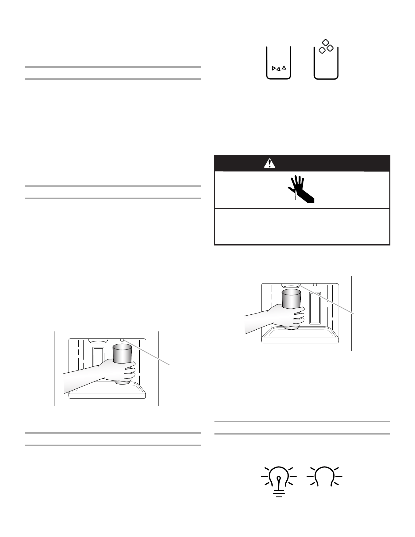
1. Press a sturdy glass against the water dispenser pad. Hold
the glass close to the water dispenser spout to ensure that the
water dispenses into the glass.
2. Remove the glass to stop dispensing.
The Ice Dispenser
Ice dispenses from the ice maker storage bin in the freezer when
the dispenser pad is pressed. To turn off the ice maker, see “Ice
Maker and Storage Bin.”
Your ice maker can produce both crushed and cubed ice. Before
dispensing ice, select which type of ice you prefer by pressing the
ICE TYPE button.
The display screen indicates which type of ice is selected.
For crushed ice, cubes are crushed before being dispensed. This
may cause a slight delay when dispensing crushed ice. Noise
from the ice crusher is normal, and pieces of ice may vary in size.
When changing from crushed to cubed, a few ounces of crushed
ice will be dispensed along with the first cubes.
To Dispense Ice:
1. Make sure the desired type of ice is selected. To switch
between cubed and crushed, press ICE TYPE.
2. Press a sturdy glass against the ice dispenser pad. Hold the
glass close to the ice guide to ensure that the ice dispenses
into the glass.
IMPORTANT: You do not need to apply a lot of pressure to the
pad in order to activate the ice dispenser. Pressing hard will
not make the ice dispense faster or in greater quantities.
3. Remove the glass to stop dispensing.
NOTE: Ice may continue to dispense for several seconds after
removing the glass from the pad. The dispenser may continue
to make noise for a few seconds after dispensing.
The Dispenser Light
When you use the dispenser, the light will automatically turn on.
If you want the light to be on continuously, you may choose either
ON or DIM. The display screen indicates which mode is selected.
A. Water dispenser spout
A
CRUSHED CUBED
A. Ice guide
ON DIM
Cut Hazard
Use a sturdy glass when dispensing ice.
Failure to do so can result in cuts.
WARNING
A
8
ON: Press LIGHT to turn the dispenser light on.
DIM: Press LIGHT a second time to select DIM mode. The
dispenser light will remain on, but at a lower intensity.
OFF: Press LIGHT a third time to turn the dispenser light off.
The dispenser lights are LEDs that cannot be changed. If it
appears that your dispenser lights are not working, see
“Troubleshooting” or “Problem Solver” for more information.
The Dispenser Lock
The dispenser can be turned off for easy cleaning or to avoid
unintentional dispensing by small children and pets.
NOTE: The lock feature does not shut off power to the refrigerator,
to the ice maker, or to the dispenser light. It simply deactivates the
controls and dispenser pads. To turn off the ice maker, see “Ice
Maker and Storage Bin.”
■ Press and hold LOCK for 3 seconds to lock the dispenser.
■ Press and hold LOCK a second time to unlock the dispenser.
The display screen indicates when the dispenser is locked.
Ice Maker and Storage Bin
■ Allow 24 hours to produce the first batch of ice. Discard the
first three batches of ice produced.
■ The quality of your ice will be only as good as the quality of the
water supplied to your ice maker. Avoid connecting the ice
maker to a softened water supply. Water softener chemicals
(such as salt) can damage parts of the ice maker and lead to
poor quality ice. If a softened water supply cannot be avoided,
make sure the water softener is operating properly and is well
maintained.
■ Do not use anything sharp to break up the ice in the storage
bin. This can cause damage to the ice container and the
dispenser mechanism.
■ Do not store anything on top of or in the ice maker or
storage bin.
Style 1
Turning the Ice Maker On/Off:
The On/Off switch can only be accessed when the ice storage bin
has been removed. The switch is located on the freezer door, on
the left side of the wall that surrounds the ice storage bin. See the
following section for bin removal instructions.
■ To turn on the ice maker, slide the control to the ON (left)
position.
■ To manually turn off the ice maker, slide the control to the
OFF (right) position.
NOTE: The ice maker has an automatic shutoff to keep the
storage bin from overfilling during normal operation. The ice
maker sensors will automatically stop ice production, but the
control will remain in the ON (left) position.
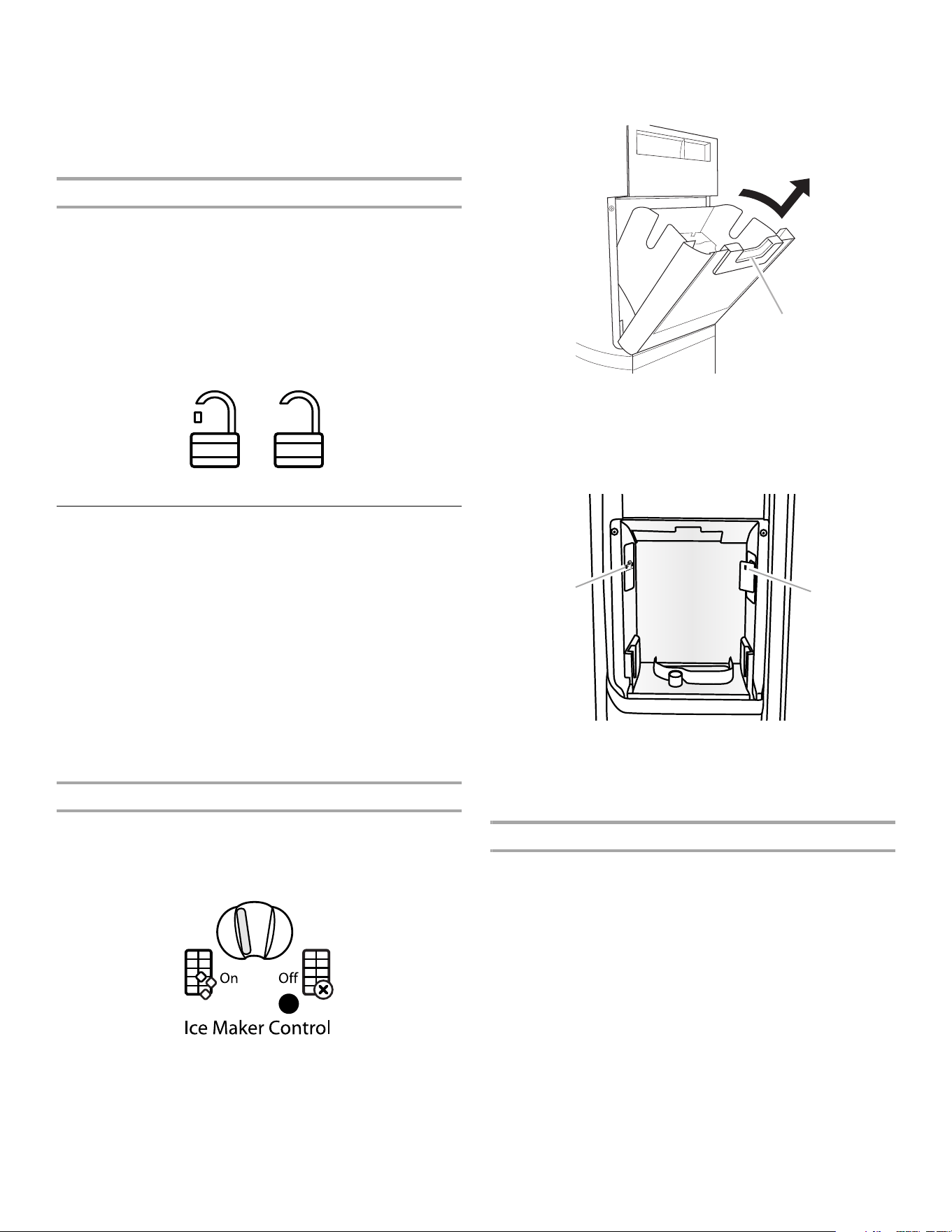
Removing and Replacing the Ice Storage Bin:
1. Press down the release lever and tilt the bucket outward. Use
both hands to hold the base of the storage bin, then lift it up
and out.
NOTE: It is not necessary to turn the ice maker control to the
OFF (right) position when removing the storage bin. The
sensor cover (“flipper door”), located on the right wall of the
freezer door, stops the ice maker from producing ice if the
door is open or the storage bin is removed.
2. Replace the bin by sliding it onto the door, then tilting it back
into an upright position. The release lever will click when the
bin is securely in place.
Style 2
Turning the Ice Maker On/Off:
■ To turn ON the ice maker, simply lower the wire shutoff arm.
■ To manually turn off the ice maker, lift the wire shutoff arm to
the OFF (arm up) position and listen for the click. Ice can still
be dispensed, but no more can be made.
NOTE: The ice maker has an automatic shutoff to keep the
storage bin from overfilling during normal operation. As ice is
made, the ice cubes will fill the ice storage bin, and the ice cubes
will raise the wire shutoff arm to the OFF (arm up) position. Do not
force the wire shutoff arm up or down.
LOCKED UNLOCKED
A. Release lever
A. On/Off switch
B. Sensor cover
A
B
A
9
Removing and Replacing the Ice Storage Bin:
1. Pull the covering panel up from the bottom.
2. Lift the wire shutoff arm so it clicks into the OFF (up) position.
3. Lift up the front of the storage bin and pull it out.
4. Replace the bin by pushing it in all the way or the dispenser
will not work.
5. To restart ice production, push the wire shutoff arm down to
the ON position. Make sure the door is closed tightly.
Water Filtration System
Water Filter Status Light
The water filter status light will help you know when to change
your water filter.
■ When the dispenser control panel’s water filter status display
changes to “ORDER,” this tells you that it is almost time to
change the water filter cartridge.
■ Replace the water filter cartridge when the water filter status
display changes to “REPLACE.”
NOTE: If water flow to your water dispenser or ice maker
decreases noticeably, change the filter sooner. The filter
should be replaced at least every 6 months, depending on
your water quality and usage.
Resetting the Filter Status
■ After changing the water filter, reset the status light by
pressing and holding the FILTER button for 3 seconds.
When the system is reset, the “ORDER” and “REPLACE”
icons will disappear from the display screen.
Changing the Water Filter
1. Locate the water filter in the top-right corner of the refrigerator
compartment.
2. Lift open the filter cover door. The filter will be released and
then be ejected as the door is opened.
3. When the door is completely open, pull the filter straight out.
NOTE: There may be some water in the filter. Some spilling
may occur. Use a towel to wipe up any spills.
4. Take the new filter out of its packaging and remove the covers
from the O-rings. Be sure the O-rings are still in place after the
covers are removed.
5. With the arrow pointing up, align the new filter with the filter
housing and slide it into place. The filter cover door will
automatically begin to close as the new filter is inserted.
6. Close the filter cover door completely in order to snap the filter
into place. You may need to press hard.
7. Flush the water system. See “Water and Ice Dispensers.”
REFRIGERATOR CARE
Cleaning
Both the refrigerator and freezer sections defrost automatically.
However, clean both sections about once a month to avoid
buildup of odors. Wipe up spills immediately.
IMPORTANT: Because air circulates between both sections, any
odors formed in one section will transfer to the other. You must
thoroughly clean both sections to eliminate odors. To avoid odor
transfer and drying out of food, wrap or cover foods tightly.
To Clean Your Refrigerator:
NOTE: Do not use abrasive or harsh cleaners such as window
sprays, scouring cleansers, flammable fluids, cleaning waxes,
concentrated detergents, bleaches or cleansers containing
petroleum products on plastic parts, interior and door liners or
gaskets. Do not use paper towels, scouring pads, or other harsh
cleaning tools.
1. Unplug refrigerator or disconnect power.
2. Hand wash, rinse, and dry removable parts and interior
surfaces thoroughly. Use a clean sponge or soft cloth and a
mild detergent in warm water.
3. Wash stainless steel and painted metal exteriors with a clean
sponge or soft cloth and a mild detergent in warm water.
4. There is no need for routine condenser cleaning in normal
home operating environments. If the environment is
particularly greasy or dusty, or there is significant pet traffic in
the home, the condenser should be cleaned every 2 to
3 months to ensure maximum efficiency.
If you need to clean the condenser:
■ Remove the base grille. See the “Door Removal”
instructions, either in the User Instructions or the
Installation Instructions and Owner’s Manual, or in the
separate instruction sheet provided with your refrigerator.
■ Use a vacuum cleaner with a soft brush to clean the grille,
the open areas behind the grille and the front surface area
of the condenser.
■ Replace the base grille when finished.
5. Plug in refrigerator or reconnect power.
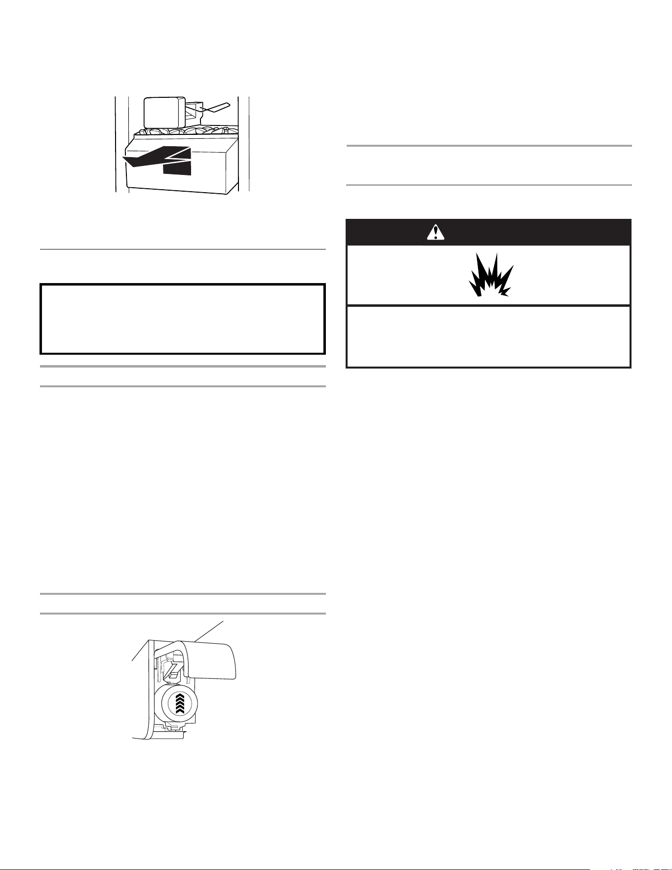
Do not use with water that is microbiologically unsafe or
of unknown quality without adequate disinfection before
or after the system. Systems certified for cyst reduction
may be used on disinfected waters that may contain
filterable cysts.
WARNING
Explosion Hazard
Use nonflammable cleaner.
Failure to do so can result in death, explosion, or fire.

10
Lights
The interior and dispenser lights are LEDs that cannot be
changed.
■ If the dispenser lights do not appear to be working as
described in “Water and Ice Dispensers” (in the User
Instructions, User Guide, or Use & Care Guide) or if the interior
lights do not illuminate when either door is opened, call for
assistance or service. See either the front cover or the
Warranty for contact information.
Vacation and Moving Care
Vacations
If You Choose to Leave Refrigerator On While You Are Away:
1. Use up any perishables and freeze other items.
2. If your refrigerator has an automatic ice maker and is
connected to the household water supply, turn off the water
supply to the refrigerator. Property damage can occur if the
water supply is not turned off.
3. If you have an automatic ice maker, turn off the ice maker.
NOTE: Depending on your model, raise the wire shutoff arm to
OFF (up) position or press the switch to OFF (right).
4. Empty the ice bin.
If You Choose to Turn Refrigerator Off Before You Leave:
1. Remove all food from the refrigerator.
2. If your refrigerator has an automatic ice maker:
■ Turn off the water supply to the ice maker at least one day
ahead of time.
■ When the last load of ice drops, raise the wire shutoff arm
to the OFF (up) position or move the switch to the OFF
(right) setting.
3. Depending on the model, turn the Refrigerator Control to OFF
or turn cooling off. See “Using the Controls” in the User
Instructions, User Guide, or Use & Care Guide.
4. Clean refrigerator, wipe it, and dry well.
5. Tape rubber or wood blocks to the tops of both doors to prop
them open far enough for air to get in. This stops odor and
mold from building up.
Moving
When you are moving your refrigerator to a new home, follow
these steps to prepare it for the move.
1. If your refrigerator has an automatic ice maker:
■ Turn off the water supply to the ice maker at least one day
ahead of time.
■ Disconnect the water line from the back of the refrigerator.
■ When the last load of ice drops, raise the wire shutoff arm
to the OFF (up) position or move the switch to the OFF
(right) setting.
2. Remove all food from the refrigerator and pack all frozen food
in dry ice.
3. Empty the ice bin.
4. Depending on the model, turn the Refrigerator Control to OFF
or turn cooling off. See “Using the Controls” in the User
Instructions, User Guide, or Use & Care Guide.
5. Unplug refrigerator.
6. Clean, wipe, and dry thoroughly.
7. Take out all removable parts, wrap them well, and tape them
together so they don’t shift and rattle during the move.
8. Depending on the model, raise the front of the refrigerator so it
rolls more easily OR screw in the leveling legs so they don't
scrape the floor. See “Adjust the Doors” or “Door Removal,
Leveling and Alignment.”
9. Tape the doors closed and tape the power cord to the back of
the refrigerator.
When you get to your new home, put everything back and refer to
the Installation Instructions for preparation instructions. Also, if
your refrigerator has an automatic ice maker, remember to
reconnect the water supply to the refrigerator.
11
PROBLEM SOLVER
First try the solutions suggested here or visit our website and reference FAQs (Frequently Asked Questions)
to possibly avoid the cost of a service call.
In the U.S.A., www.whirlpool.com In Canada, www.whirlpool.ca
GENERAL OPERATION Possible Causes and/or Recommended Solutions
Refrigerator
will not operate
■ Not connected to an electrical supply - Plug the power cord into a grounded 3 prong outlet.
Do not use an extension cord.
■ No power to the electrical outlet - Plug in a lamp to see if the outlet is working.
■ Household fuse has blown or circuit breaker has tripped - Replace the fuse or reset the circuit
breaker. If the problem continues, contact a licensed electrician.
■ Control or cooling is not turned on - Turn on the refrigerator control, or turn cooling on.
See “Using the Controls.”
■ New installation - Following installation, allow 24 hours for the refrigerator and freezer to cool
completely.
NOTE: Adjusting the temperature control(s) to the coldest setting will not cool either
compartment (refrigerator or freezer) more quickly.
Motor seems to
run too much
■ Your new refrigerator has an energy-efficient motor - The refrigerator may run longer than
you’re used to, because the compressor and fans operate at lower speeds that are more
energy-efficient. This is normal.
NOTE: Your refrigerator may run even longer if the room is warm, a large load of food is added,
the doors are opened often, or if a door has been left open.
Refrigerator seems noisy The compressor in your new refrigerator regulates temperature more efficiently and uses less energy
than older models. During various stages of operation, you may hear normal operating sounds that
are unfamiliar.
The following noises are normal:
■ Buzzing/Clicking - Heard when the water valve opens and closes to dispense water or fill the ice
maker. If the refrigerator is connected to a water line, this is normal. If the refrigerator is not
connected to a water line, turn off the ice maker.
■ Cracking/Crashing - Heard when ice is ejected from the ice maker mold.
■ Popping - Heard when the inside walls contract/expand, especially during initial cooldown.
■ Pulsating/Whirring - Heard when the fans/compressor adjust to optimize performance during
normal operation.
■ Rattling - Heard when water passes through the water line, or due to the flow of refrigerant.
Rattling may also come from items placed on top of the refrigerator.
■ Water running or gurgling - Heard when ice melts during the defrost cycle and water runs into
the drain pan.
■ Sizzling - Heard when water drips onto the heater during the defrost cycle.
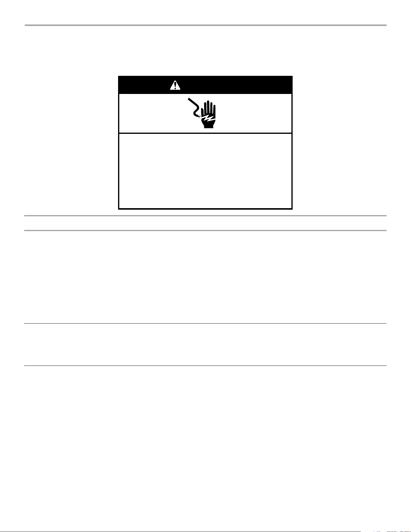
Electrical Shock Hazard
Plug into a grounded 3 prong outlet.
Do not remove ground prong.
Do not use an adapter.
Do not use an extension cord.
Failure to follow these instructions can result in death,
fire, or electrical shock.
WARNING
12
Temperature is too warm ■ New installation - Following installation, allow 24 hours for the refrigerator and freezer to cool
completely.
NOTE: Adjusting the temperature control(s) to the coldest setting will not cool either
compartment (refrigerator or freezer) more quickly.
■ Doors are opened often or not closed completely - This allows warm air to enter the
refrigerator. Minimize door openings, keep the doors fully closed, and make sure both doors are
properly sealed.
■ Air vents are blocked - Remove items that are immediately in front of the vents.
■ Large amount of warm food recently added - Allow several hours for the refrigerator to return
to its normal temperature.
■ Controls are not set correctly for the surrounding conditions - Adjust the controls to a colder
setting. Check the temperature again in 24 hours.
Temperature is too cold ■ Controls are not set correctly for the surrounding conditions - Adjust the controls to a
warmer setting. Check the temperature again in 24 hours.
■ Top refrigerator shelf is colder than lower shelves - On some models, air from the freezer
enters the refrigerator compartment through vents near the top refrigerator shelf. As a result, the
top shelf can be slightly colder than lower shelves.
■ Air vents are blocked - Remove items that are immediately in front of the vents.
Interior moisture buildup NOTE: Some moisture buildup is normal. Clean with a soft dry cloth.
■ Room is humid - A humid environment contributes to moisture buildup. Use the refrigerator only
in an indoor location, with as little humidity as possible.
■ Doors are opened often or not closed completely - This allows humid air to enter the
refrigerator. Minimize door openings, keep the doors fully closed, and make sure both doors are
properly sealed.
Interior lights do not work
■ Doors have been open for an extended period of time - Close the doors to reset the lights.
■ Light bulb is loose in the socket or has burned out - On models with incandescent interior
light bulbs, tighten or replace the bulb. See “Lights.”
NOTE: On models with LED lights, call for assistance or service if the interior lights do not illuminate
when either door is opened. See either the front cover or the Warranty for contact information.
Dispenser lights
do not work
(on some models)
■ Dispenser light is turned off - On some models, if the dispenser light is set to OFF, the light will
turn on only when a dispenser pad/lever is pressed. If you want the dispenser light to stay on
continuously, select a different setting. See “Water and Ice Dispensers.”
■ Dispenser light is set to AUTO or NIGHT LIGHT - On some models, if the dispenser light is set
to AUTO or NIGHT LIGHT, make sure the dispenser light sensor is not blocked. See “Water and
Ice Dispensers.”
NOTE: On models with LED lights, call for assistance or service if the dispenser lights do not operate
correctly. See either the front cover or the Warranty for contact information.
DOORS AND LEVELING Possible Causes and/or Recommended Solutions
Doors are difficult to open ■ Gaskets are dirty or sticky - Clean the gaskets and contact surfaces with mild soap and warm
water. Rinse and dry with a soft cloth.
GENERAL OPERATION Possible Causes and/or Recommended Solutions
WARNING
Explosion Hazard
Use nonflammable cleaner.
Failure to do so can result in death, explosion, or fire.
13
Doors will not
close completely
■ Door is blocked open - Move food packages away from the door. Make sure all bins and
shelves are in their correct positions. Make sure all packaging materials have been removed.
Doors appear to be uneven
■ Doors need to be aligned, or refrigerator needs to be leveled - See the leveling and door
alignment instructions.
Refrigerator rocks
and is not stable
■ Refrigerator is not level - To stabilize the refrigerator, remove the base grille and lower the
leveling feet until they touch the floor. See the leveling and door alignment instructions.
ICE AND WATER Possible Causes and/or Recommended Solutions
Ice maker is not
producing ice,
not producing
enough ice,
or producing
small/hollow ice
■ Refrigerator is not connected to a water supply, or the water supply shutoff valve is not fully
turned on - Connect the refrigerator to a water supply and make sure the water shutoff valve is
fully open.
■ Kink in the water source line - A kink in the water line can reduce water flow, resulting in decreased ice
production, small ice cubes, and/or hollow or irregularly-shaped ice. Straighten the water line.
■ Ice maker is not turned on - Turn on the ice maker. See “Ice Maker and Storage Bin.”
■ New installation - After connecting the refrigerator to a water source, flush the water system.
(See “Water and Ice Dispensers.”) Wait 24 hours for ice production to begin. Wait 72 hours for full ice
production. Discard the first three batches of ice produced.
■ Large amount of ice was recently removed - Allow sufficient time for the ice maker to produce
more ice.
■ Ice is jammed in the ice maker ejector arm - Remove ice from the ejector arm using a plastic utensil.
■ Inadequate water pressure - Verify that the household has adequate water pressure. See “Water
Supply Requirements.”
■ Water filter is installed incorrectly - Make sure the filter is properly installed. See “Water Filtration
System.”
■ A reverse osmosis water filtration system is connected to your cold water supply - This can
decrease water pressure. See “Water Supply Requirements.”
NOTE: If questions remain regarding water pressure, contact a licensed, qualified plumber.
DOORS AND LEVELING Possible Causes and/or Recommended Solutions
Cut Hazard
Use a sturdy glass when dispensing ice.
Failure to do so can result in cuts.
WARNING

14
Ice dispenser
will not operate
properly
■ Doors not closed completely - Make sure both doors are firmly closed. (On some models, only the
freezer door must be closed in order to operate the dispenser.)
■ New installation - After connecting the refrigerator to a water source, flush the water system.
(See “Water and Ice Dispensers.”) Wait 24 hours for ice production to begin. Wait 72 hours for full ice
production. Discard the first three batches of ice produced.
■ Ice maker is not turned on, or ice bin is not installed correctly - Turn on the ice maker and make sure
the ice storage bin is firmly in position. See “Ice Maker and Storage Bin.”
■ Ice is clogged or frozen together in the ice storage bin, or ice is blocking the ice delivery
chute - Remove or separate the clogged ice, using a plastic utensil if necessary. Clean the ice delivery
chute and the bottom of the ice storage bin using a warm damp cloth, then dry both thoroughly. To avoid
clogging and to maintain a fresh supply of ice, empty the storage bin and clean both the storage bin and
the delivery chute every 2 weeks.
■ Wrong ice has been added to the storage bin - Use only ice cubes produced by the current ice maker.
■ Dispenser is locked - Unlock the dispenser. See “Water and Ice Dispensers.”
■ Ice dispenser jams while dispensing crushed ice - For models with the ice storage bin on the door,
temporarily switch from crushed ice to cubed ice to clear the jam.
■ Dispenser pad/lever has been pressed too long - Ice will automatically stop dispensing. Wait a few
minutes for the dispenser to reset, then resume dispensing. Take large amounts of ice directly from the
ice bin, not through the dispenser.
■ Water pressure to the home is not at or above 30 psi (207 kPa) - The water pressure to the home
affects the flow from the dispenser. See “Water Supply Requirements.”
■ Water filter is clogged or incorrectly installed - Replace filter or reinstall it correctly. See “Water
Filtration System.”
Ice or water has an
off-taste, odor,
or gray color
■ New plumbing connections - New plumbing connections can result in off-flavored or discolored ice or
water. This problem should go away over time.
■ Ice has been stored too long - Discard the ice and wash the ice bin. Allow 24 hours for the ice maker to
produce new ice.
■ Odor has transferred from food - Use airtight moisture-proof packaging to store food.
■ Use of non-recommended water supply line - Odors and tastes can transfer from certain materials
used in non-recommended water supply lines. Use only a recommended water supply line. See “Water
Supply Requirements.”
■ There are minerals (such as sulfur) in the water - A water filter may need to be installed in order to
remove the minerals.
■ Water filter was recently installed or replaced - Gray or dark discoloration in ice or water indicates
that the water filtration system needs additional flushing. See “Water and Ice Dispensers.”
Water dispenser
will not operate
properly
■ Doors not closed completely - Make sure both doors are firmly closed. (On some models, only the
freezer door must be closed in order to operate the dispenser.)
■ Refrigerator is not connected to a water supply, or the water supply shutoff valve is not
turned on - Connect the refrigerator to a water supply and make sure the water shutoff valve is
fully open.
■ Kink in the water source line - A kink in the water line can reduce water flow to the dispenser.
Straighten the water line.
■ Water pressure to the home is not at or above 30 psi (207 kPa) - The water pressure to the home
affects the flow from the dispenser. See “Water Supply Requirements.”
■ New installation - After connecting the refrigerator to a water source, flush the water system.
See “Water and Ice Dispensers.”
■ Dispenser is locked - Unlock the dispenser. See “Water and Ice Dispensers.”
■ Water filter is clogged or incorrectly installed - Replace filter or reinstall it correctly. See “Water
Filtration System.”
■ A reverse osmosis water filtration system is connected to your cold water supply - This can
decrease water pressure. See “Water Supply Requirements.”
NOTE: If questions remain regarding water pressure, contact a licensed, qualified plumber.
ICE AND WATER Possible Causes and/or Recommended Solutions
15
ACCESSORIES
The following accessories are available for your refrigerator.
To order an accessory, call 1-800-442-9991 and ask for the part
number listed below or contact your authorized Whirlpool dealer.
In Canada, call 1-800-807-6777.
affresh
®
Stainless Steel Cleaner:
Order Part #W10355016
In Canada, order Part #W10355016B
affresh
®
Stainless Steel Wipes:
Order Part #W10355049
In Canada, order Part #W10355049B
affresh
®
Kitchen & Appliance Cleaner:
Order Part #W10355010
In Canada, order Part #W10355010B
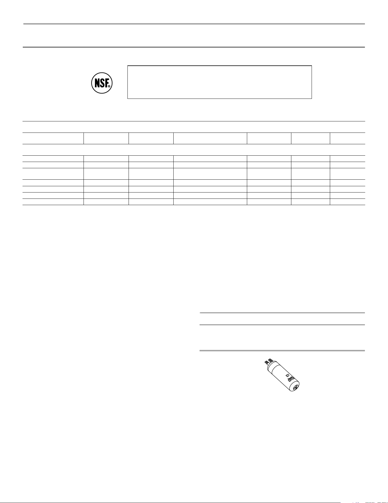
Water Filter:
Order Part #W10295370A (P4RFWB)
Air Filter:
Order Part #W10311524
Produce Preserver:
Order Part #W10346771
WATER FILTER
CERTIFICATIONS
Water is leaking or
dripping from the
dispenser
NOTE: After dispensing, a few additional drops of water are normal.
■ Glass was not held under the dispenser long enough - Hold the glass under the dispenser for
2 to 3 seconds after releasing the dispenser pad/lever.
■ New installation, or water filter was recently installed or replaced - Air in the water lines causes the
water dispenser to drip. Flush the water system to remove the air in the water lines. See “Water and Ice
Dispensers.”
■ Residual ice in the dispenser chute is melting - Make sure the ice chute is free of ice shavings or
pieces.
Water is leaking
from the back of the
refrigerator
■ Water line connections are not fully tightened - Make sure all connections are firmly tightened. See
“Connect Water Supply.”
Water from the
dispenser is
not cool enough
(on some models)
NOTE: Water from the dispenser is chilled to 50°F (10°C).
■ New installation - Allow 24 hours after installation for the water supply to cool completely.
■ Recently dispensed a large amount of water - Allow 24 hours for the new water supply to cool
completely.
■ Water has not been recently dispensed - The first glass of water may not be cool. Discard the first
glass of water dispensed.
■ Refrigerator is not connected to a cold water pipe - Make sure the refrigerator is connected to a cold
water pipe. See “Water Supply Requirements.”
ICE AND WATER Possible Causes and/or Recommended Solutions
16
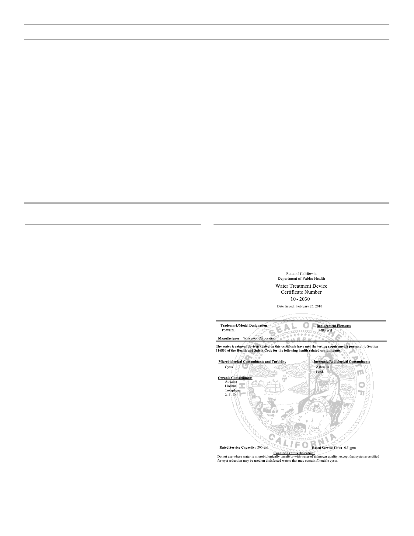
PERFORMANCE DATA SHEET
Water Filtration System
Model P5WB2L/P4RFWB Capacity 200 Gallons (757 Liters)
This system has been tested according to NSF/ANSI Standards 42 and 53 for the reduction of the substances listed below.
The concentration of the indicated substances in water entering the system was reduced to a concentration less than or equal to
the permissible limit for water leaving the system, as specified in NSF/ANSI Standards 42 and 53.
Test Parameters: pH = 7.5 ± 0.5 unless otherwise noted. Flow = 0.5 gpm (1.9 Lpm). Pressure = 60 psig (413.7 kPa).
Temp. = 68°F to 71.6°F (20°C to 22°C). Rated service capacity = 200 gallons (757 liters).
■ It is important that operational, maintenance, and filter
replacement requirements be carried out for the product to
perform as advertised. Property damage can occur if all
instructions are not followed.
■ Use replacement filter P4RFWB, part #W10295370A.
2013 suggested retail price of $39.99 U.S.A./$49.99 Canada.
Prices are subject to change without notice.
Style 1 – When the water filter status display changes from
“GOOD” to “ORDER,” order a new filter. When the filter
indicator reads “REPLACE,” it is recommended that you
replace the filter.
Style 2 – When the filter indicator changes from green to
yellow, order a new filter. When the indicator changes from
yellow to red, it is recommended that you replace the filter.
Style 3 – When the filter indicator reads 10%, order a new
filter. When the indicator reads 0%, it is recommended that
you replace the filter.
Style 4 – Press FILTER to check the status of your water filter.
If the filter indicator light is yellow, order a new filter. If the filter
indicator light is red, it is recommended that you replace the
filter.
■ After changing the water filter, flush the water system. See
“Water and Ice Dispensers” or “Water Dispenser” in the User
Instructions or User Guide.
■ These contaminants are not necessarily in your water supply.
While testing was performed under standard laboratory
conditions, actual performance may vary.
■ The product is for cold water use only.
■ The water system must be installed in compliance with state
and local laws and regulations.
■ Do not use with water that is microbiologically unsafe or of
unknown quality without adequate disinfection before or after
the system. Systems certified for cyst reduction may be used
on disinfected waters that may contain filterable cysts.
■ Refer to the “Warranty” section (in the User Instructions or
User Guide) for the Manufacturer’s name, address and
telephone number.
■ Refer to the “Warranty” section (in the User Instructions or
User Guide) for the Manufacturer’s limited warranty.
Application Guidelines/Water Supply Parameters
System tested and certified by NSF International against NSF/ANSI
Standard 42 for the reduction of Chlorine Taste and Odor, and Particulate
Class I*; and against NSF/ANSI Standard 53 for the reduction of Live
Cysts, Asbestos, Lead, Lindane, Toxaphene, Atrazine, and 2,4 - D.
Substance Reduction
Aesthetic Effects
NSF Reduction
Requirements
Average
Influent
Influent Challenge
Concentration
Maximum
Effluent
Minimum %
Reduction
Average %
Reduction
Chlorine Taste/Odor
Particulate Class I
*
50% reduction
85% reduction
2.0 mg/L
7,300,000 #/mL
2.0 mg/L ± 10%
At least 10,000 particles/mL
0.20 mg/L
75,000 #/mL
**
97
99
97.2
99.4
Contaminant
Reduction
NSF Reduction
Requirements
Average
Influent
Influent Challenge
Concentration
Maximum
Effluent
Minimum %
Reduction
Average %
Reduction
Live Cysts
†
99.95% 160,000/L 50,000/L min. 54/L
†
99.97 99.99
Asbestos 99% 87 MFL 10
7
to 10
8
fibers/L
††
0.17 MFL 99 99
Lead: @ pH 6.5
Lead: @ pH 8.5
0.010 mg/L
0.010 mg/L
0.160 mg/L
0.140 mg/L
0.15 mg/L ± 10%
0.15 mg/L ± 10%
0.001 mg/L
0.005 mg/L
99.4
98.6
99.4
98.6
Lindane 0.0002 mg/L 0.0019 mg/L 0.002 mg/L ± 10% 0.00002 mg/L 98.9 99
Toxaphene 0.003 mg/L 0.014 mg/L 0.015 mg/L ± 10% 0.001 mg/L 93 93
Atrazine 0.003 mg/L 0.0094 mg/L 0.009 mg/L ± 10% 0.0005 mg/L 94.5 94.7
2,4 - D 0.07 mg/L 0.220 mg/L 0.210 mg/L ± 10% 0.028 mg/L 87.5 96.1
Water Supply
Water Pressure
Water Temperature
Service Flow Rate
City or Well
30 - 120 psi (207 - 827 kPa)
33° - 100°F (0.6° - 37.8°C)
0.5 gpm (1.9 Lpm) @ 60 psi
*
**
†
††
Class I particle size: >0.5 to <1 um
Test requirement is at least 100,000 particles/mL of AC Fine Test Dust.
Based on the use of Cryptosporidium parvum oocysts
Fibers greater than 10 um in length
® NSF is a registered trademark of NSF International.

17
WHIRLPOOL CORPORATION MAJOR APPLIANCE
WARRANTY
LIMITED WARRANTY
For one year from the date of purchase, when this major appliance is operated and maintained according to instructions attached to or
furnished with the product, Whirlpool Corporation or Whirlpool Canada LP (hereafter “Whirlpool”) will pay for Factory Specified Parts
and repair labor to correct defects in materials or workmanship that existed when this major appliance was purchased. Service must be
provided by a Whirlpool designated service company. YOUR SOLE AND EXCLUSIVE REMEDY UNDER THIS LIMITED WARRANTY
SHALL BE PRODUCT REPAIR AS PROVIDED HEREIN. This limited warranty is valid only in the United States or Canada and applies
only when the major appliance is used in the country in which it was purchased. Proof of original purchase date is required to obtain
service under this limited warranty.
ITEMS EXCLUDED FROM WARRANTY
This limited warranty does not cover:
1. Replacement parts or repair labor if this major appliance is used for other than normal, single-family household use or when it is
used in a manner that is inconsistent to published user or operator instructions and/or installation instructions.
2. Service calls to correct the installation of your major appliance, to instruct you on how to use your major appliance, to replace or
repair house fuses, or to correct house wiring or plumbing.
3. Service calls to repair or replace appliance light bulbs, air filters or water filters. Consumable parts are excluded from warranty
coverage.
4. Damage resulting from accident, alteration, misuse, abuse, fire, flood, acts of God, improper installation, installation not in
accordance with electrical or plumbing codes, or use of products not approved by Whirlpool.
5. Cosmetic damage, including scratches, dents, chips or other damage to the finish of your major appliance, unless such damage
results from defects in materials or workmanship and is reported to Whirlpool within 30 days from the date of purchase.
6. Any food or medicine loss due to refrigerator or freezer product failures.
7. Pickup and delivery. This major appliance is intended to be repaired in your home.
8. Repairs to parts or systems resulting from unauthorized modifications made to the appliance.
9. Expenses for travel and transportation for product service if your major appliance is located in a remote area where service by an
authorized Whirlpool servicer is not available.
10. The removal and reinstallation of your major appliance if it is installed in an inaccessible location or is not installed in accordance
with Whirlpool's published installation instructions.
11. Replacement parts or repair labor on major appliances with original model/serial numbers that have been removed, altered or
cannot be easily determined.
12. Discoloration, rust, or oxidation of stainless steel surfaces.
The cost of repair or replacement under these excluded circumstances shall be borne by the customer.
DISCLAIMER OF IMPLIED WARRANTIES
IMPLIED WARRANTIES, INCLUDING ANY IMPLIED WARRANTY OF MERCHANTABILITY OR IMPLIED WARRANTY OF FITNESS FOR
A PARTICULAR PURPOSE, ARE LIMITED TO ONE YEAR OR THE SHORTEST PERIOD ALLOWED BY LAW. Some states and provinces
do not allow limitations on the duration of implied warranties of merchantability or fitness, so this limitation may not apply to you. This
warranty gives you specific legal rights, and you also may have other rights that vary from state to state or province to province.
LIMITATION OF REMEDIES; EXCLUSION OF INCIDENTAL AND CONSEQUENTIAL DAMAGES
YOUR SOLE AND EXCLUSIVE REMEDY UNDER THIS LIMITED WARRANTY SHALL BE PRODUCT REPAIR AS PROVIDED HEREIN.
WHIRLPOOL SHALL NOT BE LIABLE FOR INCIDENTAL OR CONSEQUENTIAL DAMAGES. Some states and provinces do not allow
the exclusion or limitation of incidental or consequential damages, so these limitations and exclusions may not apply to you. This
warranty gives you specific legal rights, and you also may have other rights that vary from state to state or province to province.
If outside the 50 United States and Canada, contact your authorized Whirlpool dealer to determine if another warranty applies. 7/12
For additional product information, in the U.S.A., visit www.whirlpool.com.
In Canada, visit www.whirlpool.ca.
If you do not have access to the Internet and you need assistance using your product or you would like to schedule service, you may
contact Whirlpool at the number below.
Have your complete model number ready. You can find your model number and serial number on the label, located on the inside wall of
the refrigerator compartment.
For assistance or service in the U.S.A., call 1-800-253-1301. In Canada, call 1-800-807-6777.
If you need further assistance, you can write to Whirlpool with any questions or concerns at the address below:
In the U.S.A.:
Whirlpool Brand Home Appliances
Customer eXperience Center
553 Benson Road
Benton Harbor, MI 49022-2692
In Canada:
Whirlpool Brand Home Appliances
Customer eXperience Centre
200 – 6750 Century Ave.
Mississauga, Ontario L5N 0B7
Please include a daytime phone number in your correspondence.
Please keep all provided instructions and your model number information for future reference.

18
Notes
19
LE AGRADECEMOS la compra de este producto de alta calidad. Si usted experimenta un problema que no se haya cubierto en
SOLUCIÓN DE PROBLEMAS, visite nuestro sitio de internet en www.whirlpool.com para obtener información adicional. Si
considera que aún necesita ayuda, llámenos al 1-800-253-1301. En Canadá, visite nuestro sitio de internet en www.whirlpool.ca
o llámenos al 1-800-807-6777.
Necesitará tener a mano su número de modelo y de serie ubicados
en la pared interior del compartimiento del refrigerador.
SEGURIDAD DEL REFRIGERADOR
INSTRUCCIONES PARA
EL USUARIO DEL REFRIGERADOR
Si no sigue las instrucciones de inmediato, usted puede
morir o sufrir una lesión grave.
Si no sigue las instrucciones, usted puede morir o sufrir
una lesión grave.
Todos los mensajes de seguridad le dirán el peligro potencial, le dirán cómo reducir las posibilidades de sufrir una lesión y lo que
puede suceder si no se siguen las instrucciones.
Su seguridad y la seguridad de los demás es muy importante.
Hemos incluido muchos mensajes importantes de seguridad en este manual y en su electrodoméstico. Lea y obedezca siempre
todos los mensajes de seguridad.
ADVERTENCIA
PELIGRO
Este es el símbolo de advertencia de seguridad.
Este símbolo le llama la atención sobre peligros potenciales que pueden ocasionar la muerte o una lesión a
usted y a los demás.
Todos los mensajes de seguridad irán a continuación del símbolo de advertencia de seguridad y de la palabra
“PELIGRO” o “ADVERTENCIA”. Estas palabras significan:
Para reducir el riesgo de incendio, choque eléctrico, o lesiones personales al usar su refrigerador siga
estas precauciones básicas:
ADVERTENCIA:
INSTRUCCIONES IMPORTANTES DE SEGURIDAD
CONSERVAR ESTAS INSTRUCCIONES
■ Conecte a un contacto de pared de conexión a tierra de
3 terminales.
■ No use un adaptador.
■ No quite la terminal de conexión a tierra.
■ No use un cable eléctrico de extensión.
■ Desconecte el suministro de energía antes de darle servicio.
■ Vuelva a colocar todos los componentes y paneles antes de
hacerlo funcionar.
■ Remueva las puertas de su refrigerador viejo.
■ Use un limpiador no inflamable.
■ Mantenga los materiales y vapores inflamables, tales como
gasolina, alejados del refrigerador.
■ Use dos o más personas para mover e instalar el
refrigerador.
■ Desconecte el suministro de energía antes de instalar la
fábrica de hielo (en aquellos modelos que incluyen el juego
de instalación de la fábrica de hielo).
■ Use un vaso resistente para recibir hielo del despachador
(en algunos modelos).
■ No golpee las puertas de vidrio del refrigerador (en algunos
modelos).
20
Cómo deshacerse adecuadamente de
su refrigerador viejo
IMPORTANTE: El atrapamiento y asfixia de niños no es un
problema del pasado. Los refrigeradores tirados y abandonados
son un peligro, aún si van a quedar ahí “por unos pocos días”.
Si Ud. está por deshacerse de su refrigerador viejo, por favor siga
las instrucciones que se dan a continuación para prevenir
accidentes.
Antes de tirar su viejo refrigerador o congelador:
■ Saque las puertas.
■ Deje los estantes en su lugar para que los niños no puedan
meterse con facilidad.
USO DE SU REFRIGERADOR
Instalación del filtro de aire (en algunos modelos)
En algunos modelos, el paquete de accesorios de su refrigerador
incluye un filtro de aire, el cual debe instalarse antes del uso. En
algunos modelos, el filtro de aire ya está instalado de fábrica.
El filtro de aire reduce la acumulación de olores. Esto ayuda a
mantener un ambiente más limpio dentro del refrigerador.
Cómo instalar el filtro de aire (en algunos modelos)
El filtro se debe instalar detrás de la puerta con orificios de
ventilación, la cual está ubicada (según su modelo), a lo largo de
la pared interior posterior o del lado izquierdo, cerca de la parte
superior del compartimiento del refrigerador.
1. Saque el filtro de aire del paquete.
2. Levante la puerta con orificios de ventilación para abrirla.
3. Encaje el filtro en su lugar.
4. Cierre la puerta con orificios de ventilación.
Advertencias de la Proposición 65 del estado de California:
ADVERTENCIA: Este producto contiene una o más sustancias químicas identificadas por el estado de California como
causantes de cáncer.
ADVERTENCIA: Este producto contiene una o más sustancias químicas identificadas por el estado de California como
causantes de defectos congénitos o algún otro tipo de daños en la función reproductora.
ADVERTENCIA
Peligro de Asfixia
Remueva las puertas de su refrigerador viejo.
No seguir esta instrucción puede ocasionar la muerte
o daño al cerebro.
Información importante para saber acerca del desecho
de refrigerantes:
Deshágase del refrigerador siguiendo los reglamentos
federales y locales. Los refrigerantes deberán ser evacuados
por un técnico certificado en refrigeración por EPA (Agencia
de protección del medioambiente) según los procedimientos
establecidos.
21
Cómo instalar el indicador de estado del filtro
(en algunos modelos)
El filtro viene con un indicador de estado, el cual se debe activar e
instalar en el mismo momento que se instala el filtro de aire.
1. Coloque el indicador boca abajo sobre una superficie firme y
plana.
2. Aplique presión sobre la burbuja en la parte posterior del
indicador, hasta que se reviente la misma para activar el
indicador.
3. Levante la puerta con orificios de ventilación del filtro de aire
para abrirla. En algunos modelos hay muescas detrás de la
puerta.
4. En los modelos con muescas:
■ Deslice el indicador hacia abajo, dentro de las muescas,
mirando hacia afuera.
NOTA: El indicador no se deslizará fácilmente dentro de
las muescas si no se ha reventado la burbuja posterior.
■ Cierre la puerta del filtro de aire y revise que el indicador
esté visible a través del orificio rectangular en la puerta.
En los modelos sin muescas:
■ Guarde el indicador en un lugar visible que pueda recordar
fácilmente; dentro del refrigerador o en otro lugar de la
cocina o del hogar.
Reemplazo del filtro de aire
El filtro de aire desechable deberá reemplazarse cada 6 meses,
cuando el indicador de estado haya cambiado de blanco a rojo
completamente.
Para pedir un filtro de aire de repuesto, vea “Accesorios”.
1. Quite el filtro viejo apretando las lengüetas laterales.
2. Quite el indicador de estado viejo.
3. Instale el nuevo filtro de aire y el nuevo indicador de estado
utilizando las instrucciones en las secciones anteriores.
Instalación del preservador de
alimentos frescos
(en algunos modelos)
En algunos modelos, el paquete de accesorios de su refrigerador
incluye un preservador de alimentos frescos, el cual debe
instalarse antes del uso. En algunos modelos, el preservador de
alimentos frescos ya está instalado de fábrica.
El preservador de alimentos frescos absorbe el etileno,
permitiendo que se enlentezca el proceso de maduración de
varios alimentos frescos. A consecuencia de esto, ciertos
productos permanecerán frescos por más tiempo.
La producción de etileno y el grado de sensibilidad dependen del
tipo de fruta o vegetal. Para mantener la frescura, es mejor
separar los alimentos frescos con sensibilidad al etileno, como las
frutas, ya que producen cantidades de etileno moderadas a altas.
Instalación del preservador de alimentos frescos
(en algunos modelos)
Las bolsas del preservador de alimentos frescos deberán
instalarse en su alojamiento, el cual está ubicado a lo largo de una
pared interior del cajón para verduras o el cajón convertible.
MONTHS
REPLACE
Sensibilidad
al etileno
Ritmo
de producción
de etileno
Manzanas Alta Muy alto
Espárragos Media Muy bajo
Bayas Baja Bajo
Brócoli Alta Muy bajo
Cantalupo Media Alto
Zanahorias Baja Muy bajo
Frutos cítricos Media Muy bajo
Uvas Baja Muy bajo
Lechuga Alta Muy bajo
Peras Alta Muy alto
Espinaca Alta Muy bajo
CUIDADO: PRODUCTO IRRITANTE
PUEDE IRRITAR LOS OJOS Y LA PIEL. SE FORMAN
GASES PELIGROSOS CUANDO SE MEZCLA CON
OTROS PRODUCTOS.
No lo mezcle con productos de limpieza que contengan
amoníaco, blanqueador o ácidos. No deje que entre en
contacto con los ojos, la piel o la ropa. No respire el polvo.
Manténgalo fuera del alcance de los niños.
TRATAMIENTO DE PRIMEROS AUXILIOS: Contiene
permanganato de potasio. Si se ingiere el producto, llame
inmediatamente al Poison Control Center (Servicio de
toxicología) o a un médico. No induzca al vómito. Si el
producto se introduce en los ojos, enjuague con agua
durante 15 minutos. Si entra en contacto con la piel,
enjuague con agua.
CAUTION
IR
R
ITA
N
T
Read cautions on back.
ATTENTION
IR
R
ITA
N
T
Lisez des prudences sur le revers.
22
NOTA: Para el mejor desempeño, use siempre dos bolsas.
1. Saque las bolsas del preservador de alimentos frescos de su
empaque.
2. Levante el alojamiento para quitarlo de la lengüeta de montaje
que está a lo largo de la pared.
3. Abra el alojamiento jalando hacia arriba y hacia fuera sobre la
parte posterior de la parte superior del alojamiento.
4. Coloque ambas bolsas dentro del alojamiento y cierre el
alojamiento a presión.
5. Coloque el alojamiento nuevamente sobre la lengüeta de
montaje, a lo largo de la pared.
Instalación del indicador de estado (en algunos modelos)
El preservador de alimentos frescos viene con un indicador de
estado que se debe activar e instalar en el mismo momento que
se instala la bolsa.
1. Coloque el indicador boca abajo sobre una superficie firme y
plana.
2. Aplique presión sobre la burbuja en la parte posterior del
indicador, hasta que ésta se reviente para activar el indicador.
3. Deslice la tapa que está en el alojamiento del preservador de
alimentos frescos para abrirlo.
4. Coloque el indicador en la parte superior del alojamiento,
mirando hacia fuera.
5. Cierre la tapa deslizándola y revise que el indicador esté
visible a través del orificio rectangular en la tapa.
NOTA: La tapa no se cerrará con facilidad si no se ha
reventado la burbuja posterior del indicador.
Cómo reemplazar el preservador de alimentos frescos
(en algunos modelos)
Las bolsas desechables deberán reemplazarse cada 6 meses,
cuando el indicador de estado haya cambiado de blanco a rojo
completamente.
Para pedir repuestos, vea “Accesorios”.
1. Quite las bolsas viejas del alojamiento del preservador de
alimentos frescos.
2. Quite el indicador de estado viejo.
3. Instale las nuevas bolsas y el nuevo indicador de estado
siguiendo las instrucciones en las secciones anteriores.
Uso de los controles
Los controles del refrigerador y del congelador están ubicados
sobre el panel del despachador.
IMPORTANTE: La pantalla en el panel de control del
despachador se apagará automáticamente, e ingresará al modo
de “dormir” cuando los botones del control y las almohadillas del
despachador no se hayan utilizado por 2 minutos o más. Mientras
esté en el modo de “dormir”, al presionar por primera vez un
botón de control solamente se reactivará la pantalla, sin cambiar
ningún ajuste.
■ Toque cualquier botón del control en el panel del
despachador para activar la pantalla. La pantalla principal
aparecerá como se muestra.
Cómo ajustar los controles
Para su comodidad, los controles de su refrigerador y congelador
vienen prefijados de fábrica. Al instalar su refrigerador por primera
vez, cerciórese de que los controles aún estén fijados en los
“ajustes medios”. Los puntos de ajuste recomendados de fábrica
son 37ºF (3ºC) para el refrigerador y 0ºF (-18ºC) para el
congelador.
IMPORTANTE:
■ Espere 24 horas antes de colocar alimentos en el refrigerador.
Si agrega alimentos antes de que el refrigerador se haya
enfriado por completo, sus alimentos podrían echarse a
perder.
NOTA: El ajustar los puntos fijos a un ajuste más frío que el
ajuste recomendado no hará que los compartimientos se
enfríen más rápido.
■ Si la temperatura está demasiado caliente o demasiado fría en
el refrigerador o en el congelador, antes de regular los
controles, revise primero los conductos de ventilación para
cerciorarse de que no estén obstruidos.
■ Los ajustes prefijados deben ser los correctos para un uso
doméstico normal. Los controles están ajustados
correctamente cuando la leche o los jugos están tan fríos
como Ud. desea y cuando el helado tiene consistencia firme.
■ Espere por lo menos 24 horas entre ajustes. Vuelva a verificar
las temperaturas antes de realizar otros ajustes.
Para ver y ajustar los puntos fijos, presione y sostenga el botón de
TEMP (Temperatura) por 3 segundos. Cuando el modo de ajuste
se activa, la información de ajuste aparecerá en la pantalla.
CAUTION
IRRITANT
Read cautions on back.
ATTENTION
IRRITANT
Lire les mises en garde au dos.
Whirlpool Corporation, Benton Harbor MI 49022
MONTHS
REPLACE
23
NOTA: Para ver la temperatura en grados centígrados, oprima el
botón de LIGHT (Luz) cuando el modo de ajuste se activa. Para
volver a fijar el ajuste de la pantalla a grados Fahrenheit, presione
LIGHT (Luz) nuevamente.
■ Cuando se activa el modo de ajuste, la pantalla muestra el
punto de ajuste del refrigerador y aparece “FRIDGE”
(Refrigerador).
■ Presione LOCK (Bloquear) para aumentar el punto de ajuste, o
presione FAST ICE (Hielo rápido) para bajarlo.
■ Cuando haya terminado de ver (y ajustar si lo desea) el punto
de ajuste del refrigerador, presione TEMP (Temperatura) para
que se muestre el punto de ajuste del congelador en la
pantalla. Cuando el área se haya cambiado, aparecerá
“FREEZER” (Congelador) en la pantalla.
■ Presione LOCK (Bloquear) para aumentar el punto de ajuste, o
presione FAST ICE (Hielo rápido) para bajarlo.
■ Cuando haya terminado de ver (y ajustar si lo desea) los
puntos de ajuste del refrigerador y del congelador, presione
FILTER (Filtro) para guardar los ajustes.
NOTA: Para salir sin guardar los cambios, presione ICE TYPE
(Tipo de hielo) en cualquier momento mientras se encuentre
en el modo de ajuste, o espere aproximadamente
60 segundos de inactividad y el modo de ajuste se apagará
automáticamente.
Cuando regule los puntos de ajuste de la temperatura, utilice el
siguiente cuadro como guía.
El rango de punto de ajuste para el refrigerador es de 33°F a 45°F
(0°C a 7°C). El rango de punto de ajuste para el congelador es de
-5°F a 5°F (-21°C a -15°C).
Encendido/Apagado del enfriamiento
Su refrigerador y congelador no se enfriarán cuando el
enfriamiento esté apagado.
■ Para apagar el enfriamiento, presione y sostenga los botones
de LOCK (Bloquear) y FILTER (Filtro) al mismo tiempo, por
3segundos.
IMPORTANTE: Para evitar bloquear involuntariamente el
despachador o cambiar otros ajustes, asegúrese de presionar
ambos botones exactamente al mismo tiempo.
Cuando esté apagado el enfriamiento, aparecerá
“COOLING OFF” (Enfriamiento apagado).
■ Presione y sostenga nuevamente LOCK (Bloquear) y FILTER
(Filtro) por 3 segundos para volver a encender el enfriamiento.
Características adicionales
Fast Ice (Hielo rápido)
La característica Fast Ice (Hielo rápido) ayuda en los períodos
temporarios de alto consumo de hielo al aumentar la producción
de hielo en un período de 24 horas.
IMPORTANTE: Esta característica funciona solamente si está
encendida la fábrica de hielo. Vea “Fábrica de hielo y depósito”.
■ Presione FAST ICE (Hielo rápido) para encender la
característica de Hielo rápido. Cuando la característica está
encendida, el ícono de Fast Ice (Hielo rápido) aparecerá en la
pantalla del despachador. El ajuste de Hielo rápido
permanecerá encendido durante 24 horas a menos que se
apague manualmente.
■ Para apagar manualmente la característica Fast Ice (Hielo
rápido), presione FAST ICE nuevamente para regular el punto
de ajuste del congelador. El ícono de Fast Ice (Hielo rápido)
desaparecerá cuando se apague la característica.
NOTA: Si desea en todo momento un aumento en la producción
del hielo, cambie el punto de ajuste del congelador a un ajuste
más bajo. El fijar el congelador en una temperatura más fría
puede endurecer más algunos alimentos como el helado.
Alarma de puerta entreabierta
La característica de la alarma de puerta entreabierta hace sonar
una alarma cuando la puerta del refrigerador o del congelador
esté abierta durante 5 minutos y esté funcionando el enfriamiento
del producto. La alarma se repetirá cada 2 minutos. Cierre ambas
puertas para apagarla. La característica luego se vuelve a fijar y
se reactivará cuando se deje nuevamente cualquier puerta abierta
durante 5 minutos.
NOTA: Para silenciar la alarma audible mientras que mantiene las
puertas abiertas, como por ejemplo al limpiar el interior del
refrigerador, presione cualquier botón en el panel de control.
El sonido de la alarma estará apagado temporalmente, pero el
ícono de Door Ajar (Puerta entreabierta) seguirá apareciendo en la
pantalla del panel de control del despachador.
Evaporador dual (en algunos modelos)
Algunos modelos están provistos de un sistema de dos
evaporadores secuenciales, el cual consiste en dos evaporadores
separados para los compartimientos del refrigerador y del
congelador.
Al tener una evaporación dual, se ocasionará una mayor
humedad, lo que ayuda a que los alimentos en el refrigerador no
se echen a perder tan rápido y mejora la calidad y la frescura de
los alimentos en el congelador, debido a que los alimentos se
secan menos en el mismo. Además, el sistema de evaporación
dual evita que el olor de los alimentos se transfiera al hielo en el
congelador.
NOTA: El sistema de evaporación dual siempre se activa cuando
su refrigerador está funcionando. Usted no necesita presionar
ningún botón para encenderlo.
Control de temperatura del
cajón convertible
(en algunos modelos)
Puede ajustarse el control para que enfríe de manera apropiada
las carnes o los vegetales. El aire dentro de la charola se enfría
para evitar que partes de los alimentos se congelen y puede
ajustarse para mantener la carne a las temperaturas de
almacenaje recomendadas por el National Livestock and Meat
Board (Consejo Nacional de Ganado y Carnes) de 28° a 32°F
(-2° a 0°C).
Para guardar la carne:
Fije el control en uno de los tres ajustes para MEAT (Carne), para
guardar la carne en su temperatura ideal de almacenaje.
Para guardar verduras:
Fije el control en VEG (Verduras) para guardar las verduras en sus
temperaturas óptimas de almacenaje.
NOTA: Si los alimentos se empiezan a congelar, mueva el control
hacia la derecha (menos frío), hacia el ajuste de VEG (Verduras).
Recuerde que debe esperar 24 horas entre ajustes.
CONDICIÓN: REGULACIÓN DE LA
TEMPERATURA:
REFRIGERADOR
demasiado frío
Ajuste del REFRIGERADOR
1º más alto
REFRIGERADOR
demasiado caliente
Ajuste del REFRIGERADOR
1º más bajo
CONGELADOR
demasiado frío
Ajuste del CONGELADOR
1º más alto
CONGELADOR
demasiado caliente /
Muy poco hielo
Ajuste del CONGELADOR
1º más bajo
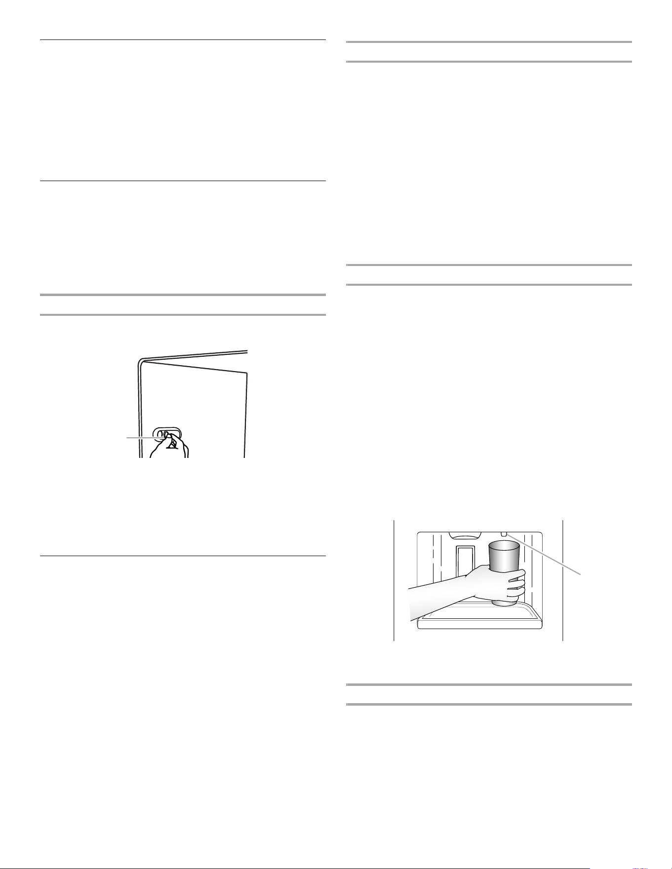
24
Control de humedad del cajón
para verduras
(en algunos modelos)
Usted puede controlar el nivel de humedad en el cajón hermético
para verduras. Regule el control a cualquier ajuste entre LOW
(Bajo) y HIGH (Alto).
LOW (Bajo - posición abierta) para el mejor almacenamiento de
frutas y verduras con cáscaras.
HIGH (Alto - posición cerrada) para el mejor almacenamiento de
vegetales de hoja frescos.
Depósito enfriador de la puerta
(en algunos modelos)
El aire frío del congelador es dirigido hacia el depósito de la
puerta del refrigerador directamente por debajo de los orificios de
ventilación.
NOTA: El compartimiento para productos lácteos y el portalatas
no están asociados con la característica del depósito enfriador de
la puerta.
Control del depósito enfriador de la puerta
El control del depósito enfriador de la puerta está situado del lado
izquierdo del compartimiento del refrigerador.
■ Deslice el control del depósito enfriador de la puerta hacia la
izquierda para reducir el flujo de aire frío hacia el depósito y
hacerlo menos frío.
■ Deslice el control del depósito enfriador de la puerta hacia la
derecha para incrementar el flujo de aire frío hacia el depósito
y hacerlo más frío.
Despachadores de agua y hielo
NOTAS:
■ El sistema de distribución no funcionará cuando cualquiera de
las puertas (la del refrigerador o la del congelador) esté
abierta.
■ Deje transcurrir 24 horas para que el refrigerador se enfríe y
pueda enfriar el agua.
■ Deje transcurrir 24 horas para la producción del primer lote de
hielo. Deshágase de los tres primeros lotes de hielo
producidos. Deje transcurrir 72 horas para la producción total
de hielo.
■ La pantalla en el panel de control del despachador se apagará
automáticamente, e ingresará al modo de “dormir” cuando los
botones del control y las almohadillas del despachador no se
hayan utilizado por 2 minutos o más. Mientras esté en el
modo de “dormir”, al presionar por primera vez un botón de
control solamente se reactivará la pantalla, sin cambiar ningún
ajuste.
Enjuague el sistema de agua
El aire en el sistema de despachado de agua puede hacer que
gotee agua del despachador. Después de haber conectado el
refrigerador a un suministro de agua o de haber reemplazado el
filtro de agua, enjuague el sistema de agua. Al enjuagar el sistema
de despachado de agua, sacará el aire de la línea de agua y del
filtro, y preparará el filtro de agua para ser usado.
NOTA: A medida que sale aire del sistema, es posible que salgan
chorros de agua repentinos del despachador.
1. Con un recipiente resistente, presione y sostenga la
almohadilla del despachador por 5 segundos, luego suéltela
por 5 segundos.
2. Repita el paso 1 hasta que el agua comience a correr.
3. Una vez que el agua haya comenzado a correr, continúe
presionando y soltando la almohadilla del despachador
(5 segundos activado, 5 segundos desactivado) hasta
despachar un total de 3 gal. (12 L).
En algunas casas se podrá requerir enjuague adicional.
El despachador de agua
IMPORTANTE:
■ Despache por lo menos 1 qt (1 L) de agua cada semana para
mantener un suministro fresco.
■ Si disminuye el flujo de agua desde el despachador, puede ser
debido a una presión de agua baja.
■ Quite el filtro de agua y despache 1 taza (237 mL) de
agua. Si 1 taza de agua se despacha en 8 segundos o
menos, la presión de agua al refrigerador satisface el
requisito mínimo.
■ Si demora más de 8 segundos en despachar 1 taza de
agua, esto significa que la presión de agua al refrigerador
es más baja de la recomendada. Vea “Requisitos del
suministro de agua” o “Solución de problemas” para
posibles soluciones.
Para despachar agua:
1. Oprima un vaso resistente contra la almohadilla del
despachador de agua. Sostenga el vaso cerca del pico del
despachador de agua, para asegurarse de que ésta se
despache dentro del vaso.
2. Retire el vaso para detener la salida del agua.
El despachador de hielo
El hielo se distribuye del depósito de la fábrica de hielo en el
congelador cuando se presiona la almohadilla del despachador.
Para apagar la fábrica de hielo, vea “Fábrica de hielo y depósito”.
Su fábrica de hielo produce hielo picado y en cubos. Antes de
sacar hielo, seleccione el tipo de hielo que desea, presionando el
botón de ICE TYPE (Tipo de hielo).
A. Control del depósito enfriador de la puerta
A
A. Pico del despachador de agua
A
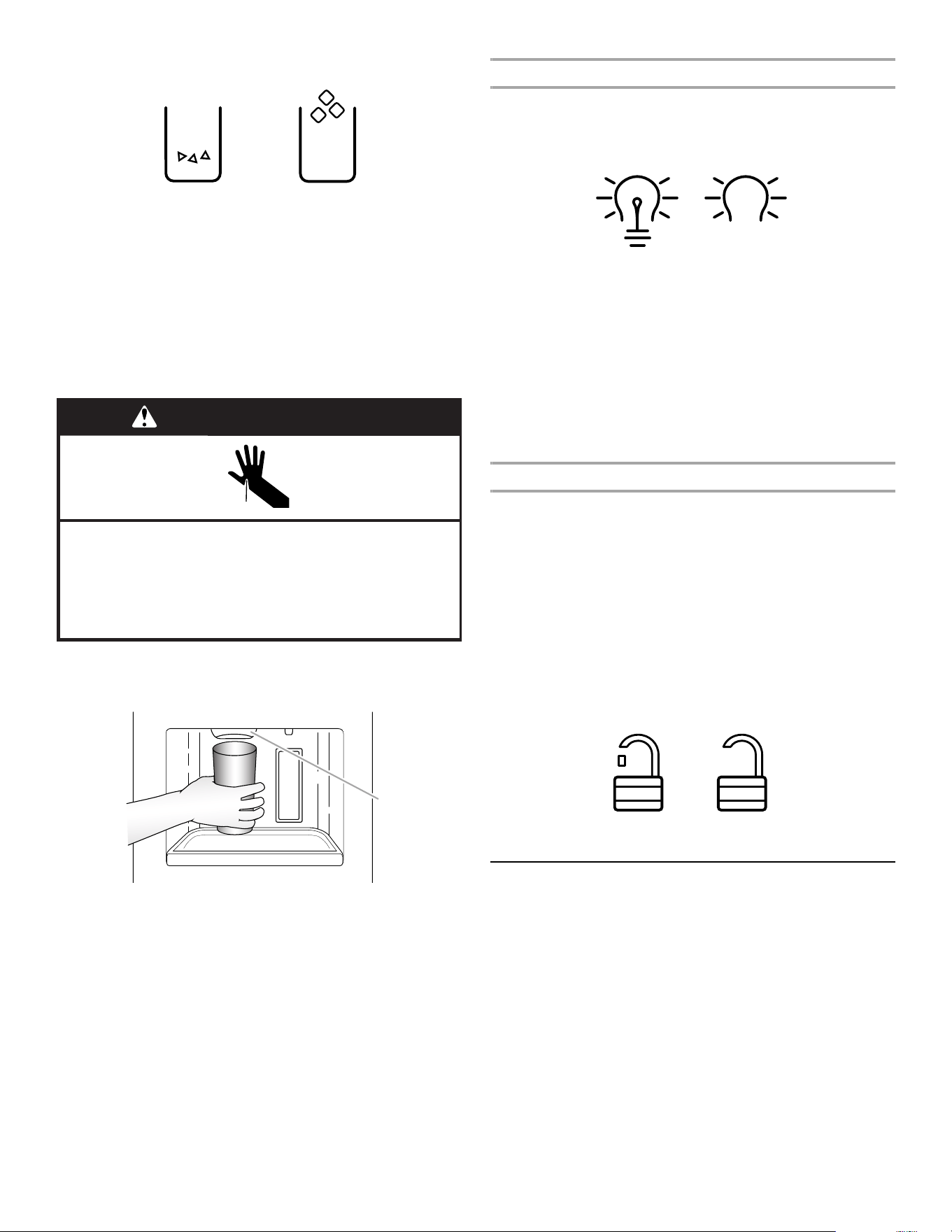
25
La pantalla indica qué tipo de hielo se ha seleccionado.
Para obtener hielo picado, el hielo es triturado antes de ser
despachado. Esto puede retrasar un poco la distribución del hielo
picado. El ruido proveniente del triturador de hielo es normal y los
trozos de hielo pueden variar en tamaño. Cuando cambie de la
posición de hielo picado a cubos, caen unas onzas de hielo
picado junto con los primeros cubos.
Para despachar hielo:
1. Asegúrese de seleccionar el tipo de hielo deseado. Para
cambiar de hielo en cubos a picado y viceversa, presione
ICE TYPE (Tipo de hielo).
2. Oprima con un vaso resistente la almohadilla del despachador
de hielo. Sostenga el vaso cerca de la guía para el hielo, para
asegurarse de que el hielo se despache dentro del vaso.
IMPORTANTE: No necesita aplicar mucha presión a la
almohadilla para activar el despachador de hielo. Oprimir
fuerte no hará que el despachador funcione con más rapidez
o produzca mayor cantidad de hielo.
3. Retire el vaso para detener la salida de hielo.
NOTA: El hielo puede continuar saliendo por varios segundos
después de haber retirado el vaso de la almohadilla. El
despachador puede continuar haciendo ruido por algunos
segundos después de haber despachado.
La luz del despachador
Cuando usted utilice el despachador, la luz se encenderá
automáticamente. Si usted desea que la luz esté encendida
continuamente, puede elegir ON (Encendido) o DIM (Tenue). La
pantalla indica qué modo está seleccionado.
ON (Encendido): Presione LIGHT (Luz) para encender la luz del
despachador.
DIM (Tenue): Presione LIGHT por segunda vez para seleccionar
el modo DIM. La luz del despachador permanecerá encendida,
pero con una intensidad más baja.
OFF (Apagado): Presione LIGHT por tercera vez para apagar la
luz del despachador.
Las luces del despachador son del tipo LED y no se pueden
cambiar. Si le parece que las luces del despachador no funcionan,
vea “Solución de problemas” para obtener más información.
El bloqueo del despachador
El despachador puede apagarse para facilitar la limpieza o para
evitar que sea activado involuntariamente por niños pequeños o
animales domésticos.
NOTA: La función de cierre no interrumpe el flujo eléctrico al
refrigerador, a la fábrica de hielo o a la luz del despachador.
Únicamente desactiva los controles y las almohadillas del
despachador. Para apagar la fábrica de hielo, vea “Fábrica de
hielo y depósito”.
■ Presione y sostenga LOCK (Bloqueo) por 3 segundos para
bloquear el despachador.
■ Presione y sostenga LOCK por segunda vez para desbloquear
el despachador.
La pantalla indica cuándo el despachador está bloqueado.
Fábrica de hielo y depósito
■ Deje transcurrir 24 horas para la producción del primer lote
de hielo. Deshágase de los tres primeros lotes de hielo
producidos.
■ La calidad del hielo dependerá de la calidad del agua que
suministre a su fábrica de hielo. Evite la conexión de su
fábrica de hielo a un suministro de agua blanda. Los químicos
para ablandar el agua (como la sal) pueden dañar ciertos
componentes de la fábrica de hielo y producir un hielo de muy
baja calidad. Si no se puede evitar el uso de un suministro de
agua blanda, asegúrese de que el ablandador de agua esté
funcionando correctamente y que goce de un buen
mantenimiento.
■ No use instrumentos afilados para romper el hielo en el
depósito. Esto puede dañar el recipiente de hielo y el
mecanismo de despachado.
■ No guarde nada encima ni dentro de la fábrica de hielo, ni en
el depósito.
CRUSHED
(Hielo picado)
CUBED
(Hielo en cubos)
A. Guía para el hielo
Peligro de Cortaduras
Use un vaso resistente para recibir hielo del
despachador.
No seguir esta instrucción puede ocasionar
cortaduras.
ADVERTENCIA
A
ON
(Encendido)
DIM
(Tenue)
LOCKED
(Bloqueado)
UNLOCKED
(Desbloqueado)
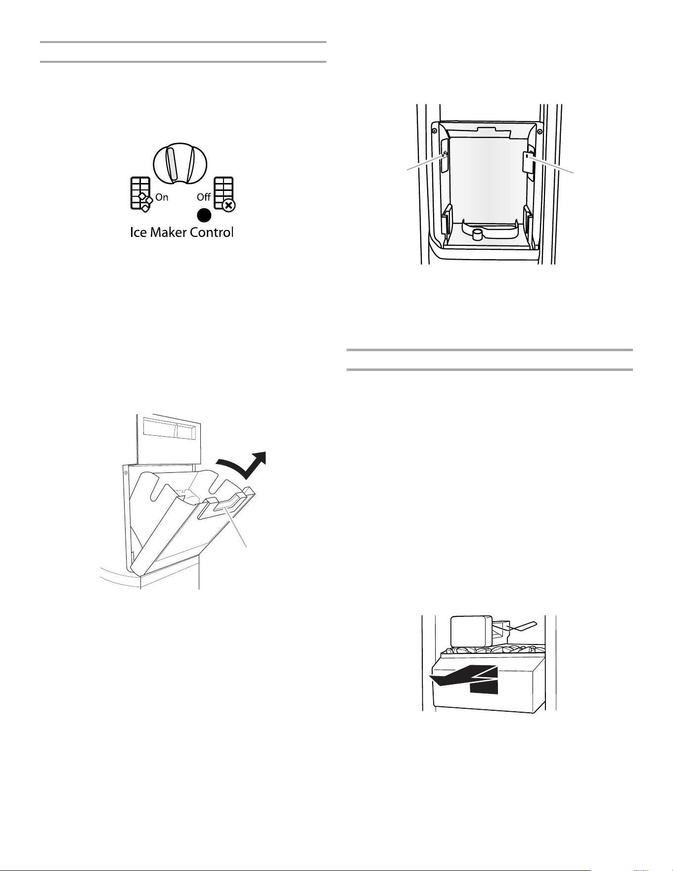
26
Estilo 1
Para encender y apagar la fábrica de hielo:
El interruptor de On/Off (Encendido/Apagado) es accesible sólo
cuando se ha quitado el depósito de hielo. El interruptor está
ubicado en la puerta del congelador, en el lado izquierdo de la
pared alrededor del depósito de hielo. Vea la siguiente sección
para obtener instrucciones para quitarlo.
■ Para poner a funcionar la fábrica de hielo, deslice el control a
la posición de ON (Encendido - hacia la izquierda).
■ Para apagar la fábrica de hielo manualmente, deslice el
control a la posición de OFF (Apagado - hacia la derecha).
NOTA: La fábrica de hielo tiene un apagado automático para
evitar que el depósito se sobrellene durante el funcionamiento
normal. Los sensores de la fábrica de hielo detendrán
automáticamente la producción de hielo, pero el control
permanecerá en la posición de ON (Encendido - hacia la
izquierda).
Cómo quitar y volver a colocar el depósito de hielo:
1. Presione hacia abajo para liberar la palanca e inclinar la
cubeta hacia fuera. Use ambas manos para sujetar la base
del depósito, luego levántelo y sáquelo.
NOTA: No es necesario girar el control de la fábrica de hielo a
la posición de OFF (Apagado - hacia la derecha) cuando quite
el depósito. La cubierta con sensor (“puerta abatible”),
ubicada en la pared derecha de la puerta del congelador, hace
que la fábrica de hielo deje de producir hielo si la puerta está
abierta o se ha quitado el depósito.
2. Vuelva a colocar el recipiente deslizándolo en la puerta e
inclinándolo nuevamente hasta quedar en posición vertical.
La palanca de liberación hará un chasquido cuando el
recipiente esté asegurado en su lugar.
Estilo 2
Para encender y apagar la fábrica de hielo:
■ Para ENCENDER la fábrica de hielo, sencillamente baje el
brazo de control de alambre.
■ Para apagar la fábrica de hielo manualmente, levante el brazo
de control de alambre a la posición OFF (Apagado - brazo
elevado) y escuche el chasquido. Aún se puede sacar hielo
del despachador pero no se puede hacer más.
NOTA: La fábrica de hielo tiene un apagado automático para
evitar que el depósito se sobrellene durante el funcionamiento
normal. A medida que se produce el hielo, los cubitos de hielo
llenarán el depósito para hielo y éstos levantarán el brazo de
control de alambre a la posición de OFF (Apagado - brazo
elevado). No fuerce el brazo de control de alambre hacia arriba o
hacia abajo.
Cómo quitar y volver a colocar el depósito de hielo:
1. Levante desde abajo el panel que cubre el depósito.
2. Eleve el brazo de control de alambre hasta que enganche en
la posición OFF (Apagado - brazo elevado).
3. Levante y jale de la parte delantera del depósito de hielo para
sacarlo.
4. Vuelva a colocar el depósito empujándolo hasta el fondo, o de
lo contrario el despachador de hielo no funcionará.
5. Para reiniciar la producción de hielo, empuje el brazo de
control de alambre hacia abajo a la posición ON (Encendido).
Cerciórese de que la puerta esté bien cerrada.
A. Palanca de liberación
A
A. Interruptor de On/Off (Encendido/Apagado)
B. Cubierta con sensor
B
A
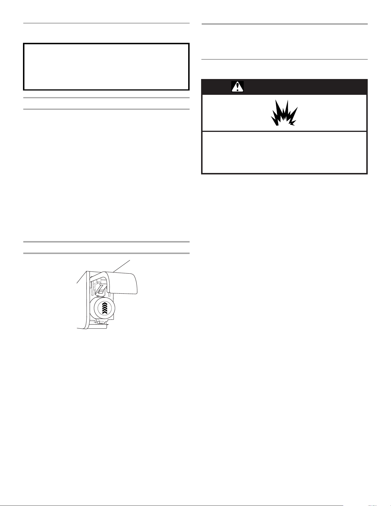
27
Sistema de filtración de agua
Luz de estado del filtro de agua
La luz del estado del filtro de agua le indicará cuándo cambiar el
filtro de agua.
■ Cuando la pantalla de estado del filtro de agua del panel de
control del despachador cambie a “ORDER” (Pedir), esto le
dirá que es casi tiempo de cambiar el cartucho del filtro
de agua.
■ Reemplace el cartucho del filtro de agua cuando la pantalla de
estado del filtro de agua cambie a “REPLACE” (Reemplazar).
NOTA: Si el flujo de agua a su despachador de agua o fábrica
de hielo disminuye notoriamente, cambie el filtro más pronto.
Se debe reemplazar el filtro al menos una vez cada 6 meses
según la calidad del agua y el uso.
Cómo fijar el estado del filtro
■ Después de cambiar el filtro de agua, reajuste la luz de estado
al presionar y sostener FILTER (Filtro) por 3 segundos.
Cuando se haya reajustado el sistema, los íconos de
“ORDER” (Pedir) y “REPLACE” (Reemplazar) desaparecerán
de la pantalla.
Cómo cambiar el filtro de agua
1. Ubique el filtro de agua que está ubicado en la esquina
superior derecha del compartimiento del refrigerador.
2. Levante la puerta de protección del filtro para abrirla. El filtro
se liberará y saldrá al mismo tiempo que se abre la puerta.
3. Cuando la puerta se haya abierto por completo, jale el filtro
hacia fuera.
NOTA: Es posible que quede agua en el filtro. Es posible que
se derrame un poco de esa agua. Use una toalla para secar
cualquier derrame.
4. Saque el filtro nuevo de su empaque y quite las cubiertas de
los anillos en O. Asegúrese de que los anillos en O sigan en su
lugar después de que se quitaron las tapas.
5. Con la flecha mirando hacia arriba, alinee el nuevo filtro con el
alojamiento del filtro y deslícelo en su lugar. La puerta de
protección del filtro comenzará a cerrarse automáticamente a
medida que se inserta el nuevo filtro.
6. Cierre por completo la puerta de protección del filtro para que
el mismo encaje en su lugar. Tal vez necesite presionar con
fuerza.
7. Enjuague el sistema de agua. Vea “Despachadores de agua y
hielo”.
CUIDADO DE SU
REFRIGERADOR
Limpieza
Tanto la sección del refrigerador como la del congelador se
descongelan automáticamente. No obstante, limpie ambas
secciones más o menos una vez al mes para evitar la
acumulación de olores. Limpie los derrames de inmediato.
IMPORTANTE: Debido a que el aire circula entre ambas
secciones, los olores que se formen en una sección pasarán a la
otra. Para eliminar los olores, limpie completamente ambas
secciones. Para evitar la transferencia de olores y la
deshidratación de los alimentos, envuelva o tape bien los
alimentos.
Para limpiar su refrigerador:
NOTA: No use productos de limpieza abrasivos o ásperos, como
aerosoles para ventanas, productos de limpieza para fregar,
líquidos inflamables, ceras para limpieza, detergentes
concentrados, blanqueadores o productos de limpieza que
contengan productos derivados del petróleo en las partes de
plástico, en el interior y en los revestimientos o juntas de la
puerta. No use toallas de papel, estropajos para fregar u otros
utensilios de limpieza ásperos.
1. Desenchufe el refrigerador o desconecte el suministro de
energía.
2. Lave a mano, enjuague y seque todas las partes
desmontables y las superficies interiores meticulosamente.
Use una esponja limpia o un paño liso y un detergente suave
en agua tibia.
3. Lave las superficies externas metálicas pintadas y de acero
inoxidable con una esponja limpia o un paño liso y detergente
suave con agua tibia.
4. No es necesaria una limpieza rutinaria del condensador en
ambientes de funcionamiento normal en el hogar. Si el
ambiente es particularmente grasoso o polvoriento, o si hay
bastante tránsito de mascotas en el hogar, el condensador
deberá limpiarse cada dos o tres meses para asegurar la
máxima eficiencia.
Si necesita limpiar el condensador:
■ Quite la rejilla de la base. Vea las instrucciones en “Cómo
quitar la puerta”, ya sea en las Instrucciones para el
usuario o en la hoja separada de instrucciones provista
con el refrigerador.
■ Use una aspiradora con un cepillo suave para limpiar la
rejilla, las áreas abiertas detrás de la rejilla y el área de la
superficie frontal del condensador.
■ Vuelva a colocar la rejilla de la base cuando termine.
5. Enchufe el refrigerador o reconecte el suministro de energía.
No use con agua que no sea microbiológicamente segura
o que sea de calidad desconocida sin desinfectarla
adecuadamente antes o después del sistema. Pueden
usarse sistemas certificados para la reducción de quistes
en aguas desinfectadas que puedan contener quistes
filtrables.
ADVERTENCIA
Peligro de Explosión
Use un limpiador no inflamable.
No seguir esta instrucción puede ocasionar la muerte,
explosión o incendio.

28
Luces
Las luces del interior y del despachador son LEDs y no se pueden
cambiar.
■ Si le parece que las luces del despachador no funcionan
como se ha descrito en “Despachadores de agua y hielo”
o las luces interiores no se encienden cuando se abre
cualquiera de las puertas, llame para solicitar ayuda o servicio
técnico. Consulte la portada o la garantía para obtener la
información de contacto.
Cuidado durante las vacaciones
ymudanzas
Vacaciones
Si Ud. decide dejar el refrigerador funcionando
mientras está ausente:
1. Use todos los artículos perecederos y congele el resto.
2. Si su refrigerador tiene una fábrica de hielo automática y está
conectada al suministro de agua de la casa, cierre el
suministro de agua al refrigerador. Si no se cierra el suministro
de agua, pueden ocurrir daños a la propiedad.
3. Si usted tiene una fábrica de hielo automática, apáguela.
NOTA: Según el modelo, levante el brazo de control de
alambre a la posición de OFF (Apagado - hacia arriba) o
presione el interruptor hacia OFF (Apagado - hacia la
derecha).
4. Vacíe el depósito de hielo.
Si Ud. decide apagar el refrigerador antes de irse:
1. Saque toda la comida del refrigerador.
2. Si su refrigerador tiene fábrica de hielo automática:
■ Cierre el suministro de agua a la fábrica de hielo por lo
menos un día antes.
■ Cuando el último lote de hielo caiga, levante el brazo de
control de alambre a la posición de OFF (Apagado - hacia
arriba) o mueva el interruptor a la posición de OFF
(Apagado - hacia la derecha).
3. Dependiendo del modelo, gire el control del refrigerador hacia
OFF (Apagado) o apague el enfriamiento. Vea “Uso de los
controles”.
4. Limpie el refrigerador, pásele un paño y séquelo bien.
5. Fije bloques de goma o de madera con cinta adhesiva a la
parte superior de ambas puertas para que queden abiertas y
el aire circule. Esto evita que se formen olores y que crezcan
hongos.
Mudanza
Si Ud. muda su refrigerador a una casa nueva, siga los pasos a
continuación para prepararse para la mudanza.
1. Si su refrigerador tiene fábrica de hielo automática:
■ Cierre el suministro de agua a la fábrica de hielo por lo
menos un día antes.
■ Desconecte la tubería de agua que está atrás del
refrigerador.
■ Cuando el último lote de hielo caiga, levante el brazo de
control de alambre a la posición de OFF (Apagado - hacia
arriba) o mueva el interruptor a la posición de OFF
(Apagado - hacia la derecha).
2. Saque toda la comida del refrigerador y empaque todos los
alimentos congelados en hielo seco.
3. Vacíe el depósito de hielo.
4. Dependiendo del modelo, gire el control del refrigerador hacia
OFF (Apagado) o apague el enfriamiento. Vea “Uso de los
controles”.
5. Desenchufe el refrigerador.
6. Limpie, pásele un paño y seque bien.
7. Saque todas las partes desmontables, envuélvalas bien y
asegúrelas con cinta adhesiva para que no se muevan ni se
sacudan durante la mudanza.
8. Según el modelo, levante la parte delantera del refrigerador
para que ruede con facilidad O BIEN atornille las patas
niveladoras para no rayar el piso. Vea “Ajuste las puertas” o
“Remoción, nivelación y alineamiento de las puertas”.
9. Sostenga las puertas cerradas y el cable a la parte posterior
del refrigerador con cinta adhesiva.
Cuando llegue a la casa nueva, ponga todo de nuevo en su lugar
y lea las Instrucciones de instalación para obtener instrucciones
de preparación. Además, si su refrigerador tiene fábrica de hielo
automática, recuerde volver a conectar el suministro de agua al
refrigerador.
29
SOLUCIÓN DE PROBLEMAS
Pruebe primero las soluciones sugeridas aquí o visite nuestro sitio de internet y consulte
“Preguntas que se hacen con frecuencia”, para evitar posiblemente el costo de una visita de servicio técnico.
En EE.UU., www.whirlpool.com En Canadá, www.whirlpool.ca
FUNCIONAMIENTO
EN GENERAL
Causas posibles y/o soluciones recomendadas
El refrigerador
no funciona
■ No está conectado a un suministro eléctrico - Enchufe el cable eléctrico en un contacto de
3 terminales con conexión a tierra. No use un cable eléctrico de extensión.
■ No hay electricidad en el contacto eléctrico - Enchufe una lámpara para ver si funciona el contacto.
■ Hay un fusible de la casa fundido o se disparó el cortacircuitos - Reemplace el fusible o reconecte
el cortacircuitos. Si el problema continúa, contacte a un electricista autorizado.
■ No está encendido el control o el enfriamiento - Encienda el control del refrigerador o el
enfriamiento. Vea “Uso de los controles”.
■ Nueva instalación - Luego de la instalación, deje que transcurran 24 horas para que el refrigerador y
el congelador se enfríen por completo.
NOTA: El ajustar el (los) control(es) de temperatura hacia la posición más fría no hará que el
compartimiento (ya sea el refrigerador o el congelador) enfríe más rápido.
El motor parece
funcionar
excesivamente
■ Su nuevo refrigerador tiene un motor con ahorro de energía - Es posible que el refrigerador
funcione por más tiempo de lo que usted está acostumbrado, ya que el compresor y los ventiladores
funcionan a velocidades más bajas que ahorran más energía. Esto es normal.
NOTA: Es posible que el refrigerador funcione por más tiempo si la habitación está caliente, si se ha
agregado una gran cantidad de alimentos, si se abren las puertas con frecuencia o si se ha dejado una
puerta abierta.
ADVERTENCIA
Peligro de Choque Eléctrico
Conecte a un contacto de pared de conexión a tierra de
3 terminales.
No quite la terminal de conexión a tierra.
No use un adaptador.
No use un cable eléctrico de extensión.
No seguir estas instrucciones puede ocasionar
la muerte, incendio o choque eléctrico.

30
El refrigerador
parece ruidoso
El compresor de su nuevo refrigerador regula la temperatura con más eficacia, y usa menos energía que
los modelos anteriores. Durante varias etapas del funcionamiento, es posible que escuche sonidos de
funcionamiento normal que no le son familiares.
Los ruidos que se indican a continuación son normales:
■ Zumbido/Chasquido - Se escucha cuando la válvula de agua se abre y se cierra para despachar
agua o llenar la fábrica de hielo. Si el refrigerador está conectado a una tubería de agua, esto es
normal. Si el refrigerador no está conectado a una tubería de agua, apague la fábrica de hielo.
■ Crujidos/Estrépitos - Se escuchan cuando el hielo es expulsado del molde de la fábrica de hielo.
■ Estallido - Se escucha cuando las paredes interiores se contraen y se expanden, especialmente
durante el enfriamiento inicial.
■ Pulsaciones/Runruneos - Se escuchan cuando los ventiladores/el compresor se ajustan para
mejorar el rendimiento durante el funcionamiento normal.
■ Vibraciones - Se escuchan cuando el agua pasa a través de la línea de agua o debido al flujo de
refrigerante. Las vibraciones también pueden ser ocasionadas por los artículos colocados sobre el
refrigerador.
■ Agua corriendo o gorgoteo - Se escucha cuando el hielo se derrite durante el ciclo de
descongelación y el agua corre hacia la bandeja recolectora.
■ Chisporroteos - Se escuchan cuando el agua gotea sobre el calentador durante el ciclo de
descongelación.
La temperatura está
demasiado elevada
■ Nueva instalación - Luego de la instalación, deje que transcurran 24 horas para que el refrigerador y
el congelador se enfríen por completo.
NOTA: El ajustar el (los) control(es) de temperatura hacia la posición más fría no hará que el
compartimiento (ya sea el refrigerador o el congelador) enfríe más rápido.
■ Se abren las puertas a menudo o no se cierran por completo - Esto hace que entre aire tibio al
refrigerador. Reduzca al mínimo las veces que abre la puerta, mantenga las puertas cerradas por
completo y cerciórese de que ambas puertas estén bien cerradas.
■ Están bloqueados los orificios de ventilación - Quite los artículos que están justo frente a los
orificios de ventilación.
■ Se ha agregado recientemente una gran cantidad de alimentos calientes - Deje que transcurran
varias horas para que el refrigerador vuelva a la temperatura normal.
■ No se han ajustado los controles correctamente de acuerdo con las condiciones
circundantes - Regule los controles un ajuste más frío. Fíjese nuevamente en la temperatura en
24 horas.
La temperatura está
demasiado baja
■ No se han ajustado los controles correctamente de acuerdo con las condiciones
circundantes - Regule los controles un ajuste más elevado. Fíjese nuevamente en la temperatura en
24 horas.
■ El estante superior del refrigerador está más frío que los estantes inferiores - En algunos
modelos, el aire del congelador entra en el compartimiento del refrigerador a través de los orificios de
ventilación, que se encuentran cerca del estante superior del refrigerador. A consecuencia de esto, el
estante superior puede estar ligeramente más frío que los estantes inferiores.
■ Están bloqueados los orificios de ventilación - Quite los artículos que están justo frente a los
orificios de ventilación.
Hay acumulación
de humedad en
el interior
NOTA: Cierta acumulación de humedad es normal. Seque con un paño suave.
■ Está húmeda la habitación - Un ambiente húmedo contribuye a que se acumule la humedad. Use el
refrigerador solamente en el interior del hogar, con el mínimo posible de humedad.
■ Se abren las puertas a menudo o no se cierran por completo - Esto hace que entre aire húmedo al
refrigerador. Reduzca al mínimo las veces que abre la puerta, mantenga las puertas cerradas por
completo y cerciórese de que ambas puertas estén bien cerradas.
Las luces interiores
no funcionan
■ Las puertas han estado abiertas por un tiempo prolongado - Cierre las puertas para volver a fijar
las luces.
■ Hay un foco flojo o quemado - En los modelos con focos interiores incandescentes, apriete el foco o
reemplácelo. Vea “Luces”.
NOTA: En los modelos con luces LED, llame para solicitar ayuda o servicio técnico si las luces interiores
no se encienden cuando se abre alguna puerta. Consulte la portada o la garantía para obtener la
información de contacto.
FUNCIONAMIENTO
EN GENERAL
Causas posibles y/o soluciones recomendadas
31
Las luces del
despachador
no funcionan
(en algunos modelos)
■ Se ha apagado la luz del despachador - En algunos modelos, si la luz del despachador se ha fijado
en OFF (Apagado), se encenderá solamente cuando se presione la paleta/palanca del despachador.
Si usted desea que la luz del despachador esté encendida continuamente, seleccione un ajuste
diferente. Vea “Despachadores de agua y hielo”.
■ Se ha fijado la luz del despachador en AUTO (Automático) o NIGHT LIGHT (Luz nocturna) - En
algunos modelos, si la luz del despachador se ha fijado en AUTO (Automático) o NIGHT LIGHT (Luz
nocturna), cerciórese de que no esté bloqueado el sensor de luz. Vea “Despachadores de agua y
hielo”.
NOTA: En los modelos con luces LED, llame para solicitar ayuda o servicio técnico si las luces del
despachador no funcionan correctamente. Consulte la portada o la garantía para obtener la información
de contacto.
PUERTAS Y NIVELACIÓN Causas posibles y/o soluciones recomendadas
Es difícil abrir las puertas ■ Las juntas están sucias o pegajosas - Limpie las juntas y las superficies de contacto con
jabón suave y agua tibia. Enjuague y seque con un paño suave.
Las puertas no cierran
completamente
■ La puerta queda abierta debido a un bloqueo - Aleje los paquetes de alimentos de la
puerta. Cerciórese de que todos los recipientes y estantes estén en su posición correcta.
Asegúrese de que se hayan quitado todos los materiales de empaque.
Las puertas parecen
estar desparejas
■ Las puertas necesitan ser alineadas o el refrigerador necesita ser nivelado - Vea las
instrucciones de nivelación y alineamiento de las puertas.
El refrigerador se tambalea
y no está estable
■ El refrigerador no está nivelado - Para estabilizar el refrigerador, quite la rejilla de la base y
baje las patas niveladoras hasta que toquen el piso. Vea las instrucciones de nivelación y
alineamiento de las puertas.
FUNCIONAMIENTO
EN GENERAL
Causas posibles y/o soluciones recomendadas
ADVERTENCIA
Peligro de Explosión
Use un limpiador no inflamable.
No seguir esta instrucción puede ocasionar la muerte,
explosión o incendio.
32
HIELO Y AGUA Causas posibles y/o soluciones recomendadas
La fábrica de hielo
no produce hielo,
no produce suficiente
hielo o produce
un hielo pequeño
o hueco
■ El refrigerador no está conectado a un suministro de agua o la válvula de cierre de suministro de
agua no está abierta por completo - Conecte el refrigerador a un suministro de agua y cerciórese de
que la válvula de cierre de agua esté completamente abierta.
■ Hay un estrechamiento en la tubería de suministro de agua - Un estrechamiento en la tubería de
agua puede reducir el flujo de agua, ocasionando una disminución de la producción de hielo, cubos de
hielo pequeños y/o huecos, o de forma irregular. Enderece la tubería de agua.
■ No se ha encendido la fábrica de hielo - Encienda la fábrica de hielo. Vea “Fábrica de hielo y
depósito”.
■ Nueva instalación - Después de haber conectado el refrigerador a un suministro de agua, enjuague el
sistema de agua. (Vea “Despachadores de agua y hielo”.) Deje transcurrir 24 horas para que la fábrica
de hielo comience a producir hielo. Deje transcurrir 72 horas para la producción total de hielo.
Deshágase de los tres primeros lotes de hielo producidos.
■ Se acaba de sacar una gran cantidad de hielo - Deje transcurrir suficiente tiempo para que la
fábrica de hielo produzca más hielo.
■ Se trabó el hielo en el brazo eyector de la fábrica de hielo - Saque el hielo del brazo eyector con un
utensilio de plástico.
■ Presión inadecuada de agua - Verifique que la casa tenga una presión de agua adecuada. Vea
“Requisitos del suministro de agua”.
■ Filtro de agua instalado de modo incorrecto - Cerciórese de que el filtro esté instalado
correctamente. Vea “Sistema de filtración de agua”.
■ Se ha conectado un sistema de filtración de agua de ósmosis inversa al suministro de agua
fría - Esto puede hacer que disminuya la presión de agua. Vea “Requisitos del suministro de agua”.
NOTA: Si aún tiene preguntas acerca de la presión de agua, llame a un plomero competente autorizado.
Peligro de Cortaduras
Use un vaso resistente para recibir hielo del
despachador.
No seguir esta instrucción puede ocasionar
cortaduras.
ADVERTENCIA

33
El despachador de
hielo no funciona
debidamente
■ Las puertas no se cierran por completo - Cerciórese de que ambas puertas estén firmemente
cerradas. (En algunos modelos, deberá cerrarse solamente la puerta del congelador para poner en
marcha el despachador.)
■ Nueva instalación - Después de haber conectado el refrigerador a un suministro de agua, enjuague el
sistema de agua. (Vea “Despachadores de agua y hielo”.) Deje transcurrir 24 horas para que la fábrica
de hielo comience a producir hielo. Deje transcurrir 72 horas para la producción total de hielo.
Deshágase de los tres primeros lotes de hielo producidos.
■ No está encendida la fábrica de hielo, o no se ha instalado correctamente el depósito de
hielo - Encienda la fábrica de hielo y cerciórese de que el depósito de hielo esté firme en su lugar.
Vea “Fábrica de hielo y depósito”.
■ Se ha atascado o congelado junto el hielo en el depósito de hielo o el mismo está bloqueando el
conducto de salida de hielo - Saque o separe el hielo que está atascado utilizando un utensilio de
plástico, si es necesario. Limpie el conducto de salida de hielo y la base del depósito de hielo con un
paño humedecido con agua tibia; luego seque ambos meticulosamente. Para evitar que se atasquen y
mantener un suministro fresco de hielo, vacíe el depósito y limpie el depósito y el conducto de salida
cada 2 semanas.
■ Se ha agregado hielo incorrecto en el depósito - Use únicamente el hielo producido por su fábrica
de hielo actual.
■ El despachador está bloqueado - Desbloquee el despachador. Vea “Despachadores de agua y
hielo”.
■ El despachador de hielo se atasca mientras vierte el hielo picado - Para los modelos con depósito
de hielo en la puerta, cambie temporalmente de hielo triturado a hielo en cubos para despejar el
depósito de hielo.
■ Se ha presionado la paleta/palanca del despachador por demasiado tiempo - El hielo dejará de
despacharse automáticamente. Espere unos minutos para que el despachador se restablezca y vuelva
a usarlo. Saque grandes cantidades de hielo directamente del depósito de hielo, y no a través del
despachador.
■ La presión de agua a la casa no está por encima de 30 lb/pulg² (207 kPa) - La presión de agua a la
casa afectará el flujo del despachador. Vea “Requisitos del suministro de agua”.
■ El filtro de agua está obstruido o instalado incorrectamente - Reemplace el filtro o vuelva a
instalarlo correctamente. Vea “Sistema de filtración de agua”.
El hielo o agua tiene
mal sabor, mal olor
o un color grisáceo
■ Son nuevas las conexiones de plomería - Las conexiones nuevas de plomería pueden producir hielo
o agua descolorido o de mal sabor. Este problema desaparecerá con el correr del tiempo.
■ Se ha guardado el hielo por demasiado tiempo - Deseche el hielo y lave el depósito de hielo. Deje
transcurrir 24 horas para que la fábrica de hielo produzca hielo nuevo.
■ Se ha transferido al hielo el olor de los alimentos - Use recipientes herméticos contra humedad
para almacenar alimentos.
■ Uso de una tubería de suministro de agua no recomendada - Es posible que se transfiera olor y
gusto de ciertos materiales usados en tuberías de suministro de agua no recomendadas. Use
solamente una tubería recomendada de suministro de agua. Vea “Requisitos del suministro de agua”.
■ El agua contiene minerales (como el azufre) - Podría ser necesario instalar un filtro de agua para
eliminar los minerales.
■ Se ha instalado o reemplazado recientemente el filtro de agua - Un descoloramiento o un color
gris del hielo o agua indican que el sistema de filtración de agua necesita enjuagarse más. Vea
“Despachadores de agua y hielo”.
HIELO Y AGUA Causas posibles y/o soluciones recomendadas

34
ACCESORIOS
Los siguientes accesorios están disponibles para su refrigerador.
Para hacer un pedido, llame al 1-800-442-9991 y solicite el
número de pieza que se detalla a continuación o póngase en
contacto con su distribuidor autorizado de Whirlpool. En Canadá,
llame al 1-800-807-6777.
Limpiador de acero inoxidable affresh
®
:
Pida la pieza No. W10355016
En Canadá, pida la pieza No. W10355016B
Toallitas húmedas para acero inoxidable affresh
®
:
Pida la pieza No. W10355049
En Canadá, pida la pieza No. W10355049B
Limpiador para cocina y electrodomésticos affresh
®
:
Pida la pieza No. W10355010
En Canadá, pida la pieza No. W10355010B
Filtro de agua:
Pida la pieza No. W10295370A (P4RFWB)
Filtro de aire:
Pida la pieza No. W10311524
Preservador de alimentos frescos:
Pida la pieza No. W10346771
El despachador de
agua no funciona
debidamente
■ Las puertas no se cierran por completo - Cerciórese de que ambas puertas estén firmemente
cerradas. (En algunos modelos, deberá cerrarse solamente la puerta del congelador para poner en
marcha el despachador.)
■ El refrigerador no está conectado a un suministro de agua o la válvula de cierre de suministro de
agua no está abierta - Conecte el refrigerador a un suministro de agua y cerciórese de que la válvula
de cierre de agua esté completamente abierta.
■ Hay un estrechamiento en la tubería de suministro de agua - Un estrechamiento en la tubería
puede reducir el flujo de agua al despachador. Enderece la tubería de agua.
■ La presión de agua a la casa no está por encima de 30 lb/pulg² (207 kPa) - La presión de agua a la
casa afectará el flujo del despachador. Vea “Requisitos del suministro de agua”.
■ Nueva instalación - Después de haber conectado el refrigerador a un suministro de agua, enjuague el
sistema de agua. Vea “Despachadores de agua y hielo”.
■ El despachador está bloqueado - Desbloquee el despachador. Vea “Despachadores de agua y
hielo”.
■ El filtro de agua está obstruido o instalado incorrectamente - Reemplace el filtro o vuelva a
instalarlo correctamente. Vea “Sistema de filtración de agua”.
■ Se ha conectado un sistema de filtración de agua de ósmosis inversa al suministro de agua
fría - Esto puede hacer que disminuya la presión de agua. Vea “Requisitos del suministro de agua”.
NOTA: Si aún tiene preguntas acerca de la presión de agua, llame a un plomero competente autorizado.
Hay fugas de agua
o goteos en el
despachador
NOTA: Es normal que haya algunas gotas de agua después de despachar agua.
■ No se ha puesto el vaso debajo del despachador el tiempo suficiente - Sostenga el vaso debajo
del despachador durante 2 a 3 segundos después de soltar la paleta/palanca del despachador.
■ Es nueva la instalación o se ha instalado o reemplazado recientemente el filtro de agua - El aire
en las líneas de agua hará que gotee agua del despachador. Enjuague el sistema de agua para quitar
el aire que se encuentra en las líneas de agua. Vea “Despachadores de agua y hielo”.
■ Se están derritiendo los restos de hielo en el conducto del depósito - Cerciórese de que el
conducto de hielo esté libre de escarcha o pedazos de hielo.
Hay fugas de agua
de la parte trasera
del refrigerador
■ Las conexiones de la línea de agua no están ajustadas por completo - Cerciórese de que todas
las conexiones estén firmemente ajustadas. Vea “Conexión del suministro de agua”.
El agua del
despachador
no está lo
suficientemente fría
(en algunos modelos)
NOTA: El agua del despachador se enfría a 50°F (10°C).
■ Nueva instalación - Deje transcurrir 24 horas después de la instalación para que el suministro de
agua se enfríe completamente.
■ Se ha despachado una gran cantidad de agua recientemente - Deje transcurrir 24 horas para que
el nuevo suministro de agua se enfríe por completo.
■ No se ha usado el despachador de agua recientemente - Puede ser que el primer vaso de agua no
esté frío. Descarte el agua del primer vaso.
■ El refrigerador no está conectado a una tubería de agua fría - Asegúrese de que el refrigerador
esté conectado a una tubería de agua fría. Vea “Requisitos del suministro de agua”.
HIELO Y AGUA Causas posibles y/o soluciones recomendadas
35
HOJA DE DATOS DEL RENDIMIENTO
Sistema de filtración de agua
Modelo P5WB2L/P4RFWB Capacidad de 200 galones (757 litros)
Este sistema ha sido comprobado según las normas 42 y 53 NSF/ANSI para la reducción de las sustancias citadas a continuación.
La concentración de las sustancias indicadas en agua entrando al sistema fue reducida a una concentración menor o igual al límite
permitido para agua saliendo del sistema, tal como se especifica en las normas 42 y 53 NSF/ANSI.
Parámetros de la prueba: pH = 7,5 ± 0,5 si no se indica lo contrario. Flujo = 0,5 gpm (1,9 Lpm). Presión = 60 lbs/pulg² (413,7 kPa).
Temp. = 68°F a 71,6°F (20°C a 22°C). Capacidad nominal de servicio = 200 galones (757 litros).
■ Es importante que los requerimientos de operación,
mantenimiento y reemplazo del filtro se lleven a cabo para que
el producto se desempeñe tal como se ofrece en la
publicidad. Pueden ocurrir daños a la propiedad si no se
siguen todas las instrucciones.
■ Use el filtro de repuesto P4RFWB, pieza N° W10295370A.
El precio sugerido de venta al por menor durante el año 2013
es de $39,99 en EE.UU./$49,99 en Canadá. Los precios están
sujetos a cambio sin previo aviso.
Estilo 1 – Cuando la pantalla de estado del filtro de agua
cambie de “GOOD” (Bueno) a “ORDER” (Pedir), pida un
nuevo filtro. Cuando el indicador del filtro muestre “REPLACE”
(Reemplazar), se recomienda que reemplace el filtro.
Estilo 2 – Cuando el indicador del filtro cambie de verde a
amarillo, pida un nuevo filtro. Cuando el indicador cambie de
amarillo a rojo, se recomienda que reemplace el filtro.
Estilo 3 – Cuando el indicador del filtro muestre 10%, pida un
nuevo filtro. Cuando el indicador muestre 0%, se recomienda
que reemplace el filtro.
Estilo 4 – Presione FILTER (Filtro) para controlar el estado de
su filtro de agua. Si la luz indicadora del filtro está amarilla,
pida un nuevo filtro. Si la luz indicadora está roja, se
recomienda que reemplace el filtro.
■ Después de cambiar el filtro de agua, enjuague el sistema de
agua. Vea “Despachadores de agua y hielo” o “Despachador
de agua”.
■ Estos contaminantes no se encuentran necesariamente en su
suministro de agua. Si bien se realizaron las pruebas bajo
condiciones de laboratorio estándares, el desempeño real
puede variar.
■ El producto es para uso con agua fría únicamente.
■ El sistema de agua deberá instalarse conforme a las leyes y
normas estatales y locales.
■ No use con agua que no sea microbiológicamente segura o
que sea de calidad desconocida sin desinfectarla
adecuadamente antes o después del sistema. Pueden usarse
sistemas certificados para la reducción de quistes en aguas
desinfectadas que puedan contener quistes filtrables.
■ Refiérase a la sección “Garantía” para obtener el nombre,
dirección y número telefónico del fabricante.
■ Refiérase a la sección “Garantía” para verificar la garantía
limitada del fabricante.
Pautas de aplicación / Parámetros para el suministro de agua
Sistema comprobado y certificado por NSF International, según la
norma 42 NSF/ANSI para la reducción de cloro, sabor y olor, y clase
de partículas I*; y según la norma 53 NSF/ANSI para la reducción de
quistes vivos, asbestos, plomo, lindano, toxafeno, atrazina, y 2,4 - D.
Reducción de sustancias
Efectos estéticos
Requisitos de
reducción de NSF
Promedio
influente
Concentración en
el agua a tratar
Máximo
efluente
% Mínimo
reducción
%Promedio
reducción
Cloro, sabor/olor
Clase de partículas I
*
50% reducción
85% reducción
2,0 mg/L
7.300.000 #/mL
2,0 mg/L ± 10%
Por lo menos
10.000 partículas/mL
0,20 mg/L
75.000 #/mL
**
97
99
97,2
99,4
Reducción de
contaminantes
Requisitos de
reducción de NSF
Promedio
influente
Concentración en
el agua a tratar
Máximo
efluente
% Mínimo
reducción
%Promedio
reducción
Quistes vivos
†
99,95% 160.000/L 50.000/L min. 54/L
†
99,97 99,99
Asbestos 99% 87 MFL 10
7
a 10
8
fibras/L
††
0,17 MFL 99 99
Plomo: @ pH 6,5
Plomo: @ pH 8,5
0,010 mg/L
0,010 mg/L
0,160 mg/L
0,140 mg/L
0,15 mg/L ± 10%
0,15 mg/L ± 10%
0,001 mg/L
0,005 mg/L
99,4
98,6
99,4
98,6
Lindano 0,0002 mg/L 0,0019 mg/L 0,002 mg/L ± 10% 0,00002 mg/L 98,9 99
Toxafeno 0,003 mg/L 0,014 mg/L 0,015 mg/L ± 10% 0,001 mg/L 93 93
Atrazina 0,003 mg/L 0,0094 mg/L 0,009 mg/L ± 10% 0,0005 mg/L 94,5 94,7
2,4 - D 0,07 mg/L 0,220 mg/L 0,210 mg/L ± 10% 0,028 mg/L 87,5 96,1
Suministro de agua
Presión del agua
Temperatura del agua
Flujo nominal de servicio
Municipal o de pozo
30 - 120 lbs/pulg² (207 - 827 kPa)
33° - 100°F (0,6° - 37,8°C)
0,5 gpm (1,9 Lpm) @ 60 lbs/pulg²
*
**
†
††
Tamaño de las partículas clase I: >0,5 a <1 um
El requisito de prueba es de cuando menos 100.000 partículas/ml de Polvo Fino de prueba AC.
Basado en la filtración de quistes de Cryptosporidium parvum
Fibras mayores de 10 um de longitud
® NSF es una marca registrada de NSF International.

36
GARANTÍA DE LOS ELECTRODOMÉSTICOS
PRINCIPALES DE WHIRLPOOL CORPORATION
GARANTÍA LIMITADA
Durante un año a partir de la fecha de compra, siempre y cuando se dé a este electrodoméstico principal un uso y mantenimiento de
conformidad con las instrucciones adjuntas o provistas con el producto, Whirlpool Corporation o Whirlpool Canada LP (en lo sucesivo
denominado “Whirlpool”), se hará cargo del costo de las piezas especificadas de fábrica y del trabajo de reparación para corregir
defectos en los materiales o en la mano de obra, existentes en el momento de la compra de este electrodoméstico principal. El servicio
deberá ser suministrado por una compañía de servicio designada por Whirlpool. SU ÚNICO Y EXCLUSIVO RECURSO SEGÚN LOS
TÉRMINOS DE ESTA GARANTÍA LIMITADA SERÁ EL DE REPARAR EL PRODUCTO SEGÚN SE ESTIPULA EN LA PRESENTE. Esta
garantía limitada es válida solamente en Estados Unidos o en Canadá, y se aplica solamente cuando el electrodoméstico principal se
use en el país en el que se ha comprado. Se requiere una prueba de la fecha de compra original para obtener servicio bajo esta
garantía limitada.
EXCLUSIONES DE LA GARANTÍA
Esta garantía limitada no cubre:
1. Piezas de repuesto o mano de obra si este electrodoméstico principal se usa de un modo diferente al doméstico normal de una
familia, o cuando se use de un modo contrario a las instrucciones publicadas para el usuario u operador y/o las instrucciones de
instalación.
2. Visitas de servicio técnico para corregir la instalación de su electrodoméstico principal, para enseñarle a usar su electrodoméstico
principal, para cambiar o reparar fusibles domésticos o para corregir la instalación eléctrica o de la tubería de la casa.
3. Visitas de servicio técnico para reparar o reemplazar focos para electrodomésticos, filtros de aire o filtros de agua. Las piezas de
consumo están excluidas de la cobertura de la garantía.
4. Daños causados por accidente, alteración, uso indebido, abuso, incendio, inundación, actos fortuitos, instalación incorrecta,
instalación que no esté de acuerdo con los códigos eléctricos o de plomería, o el empleo de productos no aprobados por
Whirlpool.
5. Daños estéticos, incluyendo rayaduras, abolladuras, desportilladuras u otro daño al acabado de su electrodoméstico principal, a
menos que el mismo sea debido a defectos en los materiales o la mano de obra y se le informe a Whirlpool en un lapso de 30 días
a partir de la fecha de compra.
6. Cualquier pérdida de comida o medicamentos debido a fallas del refrigerador o del congelador.
7. Recogida y entrega. Este electrodoméstico principal se ha destinado para ser reparado en el hogar.
8. Reparaciones de piezas o sistemas como resultado de modificaciones no autorizadas que se hayan efectuado en el
electrodoméstico.
9. Gastos de viaje y transporte para obtener servicio para el producto, si su electrodoméstico principal está ubicado en un lugar
remoto en el cual no haya disponible un técnico de servicio autorizado por Whirlpool.
10. La remoción y reinstalación de su electrodoméstico principal, si estuviera instalado en un lugar inaccesible o si no estuviera
instalado de conformidad con las instrucciones de instalación publicadas por Whirlpool.
11. Piezas de repuesto o mano de obra en electrodomésticos principales con números de modelo/serie originales que se hayan
removido, alterado o que no puedan ser identificados con facilidad.
12. Decoloración, herrumbre u oxidación de las superficies de acero inoxidable.
El costo de la reparación o el reemplazo bajo estas circunstancias excluidas, correrá por cuenta del cliente.
EXCLUSIÓN DE GARANTÍAS IMPLÍCITAS
LAS GARANTÍAS IMPLÍCITAS, INCLUYENDO CUALQUIER GARANTÍA IMPLÍCITA DE COMERCIABILIDAD O GARANTÍA IMPLÍCITA DE
CAPACIDAD PARA UN PROPÓSITO PARTICULAR, SERÁN LIMITADAS A UN AÑO O AL PERÍODO MÁS CORTO PERMITIDO POR LEY.
Algunos estados y provincias no permiten la limitación de la duración de garantías implícitas de comerciabilidad o aptitud, de modo
que la limitación arriba indicada quizás no le corresponda. Esta garantía le otorga derechos legales específicos, y es posible que usted
tenga también otros derechos que varían de un estado a otro o de una provincia a otra.
LIMITACIÓN DE RECURSOS; EXCLUSIÓN DE DAÑOS INCIDENTALES O CONSECUENTES
SU ÚNICO Y EXCLUSIVO RECURSO SEGÚN LOS TÉRMINOS DE ESTA GARANTÍA LIMITADA SERÁ EL DE REPARAR EL PRODUCTO
SEGÚN SE ESTIPULA EN LA PRESENTE. WHIRLPOOL NO SE RESPONSABILIZARÁ POR DAÑOS INCIDENTALES O
CONSECUENTES. Algunos estados y provincias no permiten la exclusión o limitación de daños incidentales o consecuentes, de modo
que estas limitaciones y exclusión quizás no le correspondan. Esta garantía le otorga derechos legales específicos, y es posible que
usted tenga también otros derechos que varían de un estado a otro o de una provincia a otra.
Si usted se encuentra fuera de los cincuenta Estados Unidos y Canadá, póngase en contacto con su distribuidor autorizado de
Whirlpool para determinar si corresponde otra garantía. 7/12

37
Para obtener información adicional acerca de su producto, en EE.UU. visite www.whirlpool.com.
En Canadá, visite www.whirlpool.ca.
Si usted no tiene acceso a internet y necesita ayuda para usar su producto, o si quisiera hacer una cita para obtener servicio, puede
ponerse en contacto con Whirlpool, en el número que se indica a continuación.
Tenga listo su número de modelo completo. Puede encontrar el número de modelo y de serie en la etiqueta ubicada en la pared interior
del compartimiento del refrigerador.
Si necesita ayuda o servicio técnico, en EE.UU., llame al 1-800-253-1301. En Canadá, llame al 1-800-807-6777.
Si necesita asistencia adicional, puede escribir a Whirlpool con sus preguntas o dudas a la dirección que aparece a continuación:
En los EE.UU.:
Whirlpool Brand Home Appliances
Customer eXperience Center
553 Benson Road
Benton Harbor, MI 49022-2692
En Canadá:
Whirlpool Brand Home Appliances
Customer eXperience Centre
200 – 6750 Century Ave.
Mississauga, Ontario L5N 0B7
Por favor incluya en su correspondencia un número de teléfono en el que se le pueda localizar durante el día.
Sírvase guardar todas las instrucciones provistas y la información con el número de modelo, para referencia futura.

38
Nous vous REMERCIONS d'avoir acheté ce produit de haute qualité. Si vous rencontrez un problème non mentionné dans la
section DÉPANNAGE ou RÉSOLUTION DE PROBLÈMES, veuillez visiter notre site Web www.whirlpool.com pour des
informations supplémentaires. Si vous avez toujours besoin d'assistance, veuillez nous téléphoner au 1-800-253-1301. Au
Canada, visitez notre site Web www.whirlpool.ca ou téléphonez-nous au 1-800-807-6777.
Vous aurez besoin de vos numéros de modèle et de série situés sur la paroi interne du compartiment de réfrigération.
SÉCURITÉ DU RÉFRIGÉRATEUR
INSTRUCTIONS D'UTILISATION
DU RÉFRIGÉRATEUR
Risque possible de décès ou de blessure grave si vous ne
suivez pas immédiatement les instructions.
Risque possible de décès ou de blessure grave si vous
ne suivez pas les instructions.
Tous les messages de sécurité vous diront quel est le danger potentiel et vous disent comment réduire le risque de blessure et
ce qui peut se produire en cas de non-respect des instructions.
Votre sécurité et celle des autres est très importante.
Nous donnons de nombreux messages de sécurité importants dans ce manuel et sur votre appareil ménager. Assurez-vous de
toujours lire tous les messages de sécurité et de vous y conformer.
AVERTISSEMENT
DANGER
Voici le symbole d’alerte de sécurité.
Ce symbole d’alerte de sécurité vous signale les dangers potentiels de décès et de blessures graves à vous
et à d’autres.
Tous les messages de sécurité suivront le symbole d’alerte de sécurité et le mot “DANGER” ou
“AVERTISSEMENT”. Ces mots signifient :
AVERTISSEMENT :
réfrigérateur, prendre quelques précautions fondamentales, y compris les suivantes :
Pour réduire les risques d'incendie, de choc électrique ou des blessures lors de l'utilisation du
IMPORTANTES INSTRUCTIONS DE SÉCURITÉ
CONSERVEZ CES INSTRUCTIONS
■ Brancher l'appareil sur une prise à 3 alvéoles reliée à la terre.
■ Ne pas enlever la broche de liaison à la terre.
■ Ne pas utiliser un adaptateur.
■ Ne pas utiliser un câble de rallonge.
■ Débrancher la source de courant électrique avant l'entretien.
■ Replacer pièces et panneaux avant de faire la remise en marche.
■ Enlever les portes de votre vieux réfrigérateur.
■ Utiliser un produit de nettoyage ininflammable.
■ Garder les matériaux et les vapeurs inflammables, telle
que l'essence, loin du réfrigérateur.
■ Utiliser deux ou plus de personnes pour déplacer et
installer le réfrigérateur.
■ Débrancher le réfrigérateur avant l'installation de la
machine à glaçons (seulement pour modèles prêts à
recevoir une machine à glaçons).
■ Utiliser un verre robuste pour prendre des glaçons (sur
certains modèles).
■ Ne pas heurter les portes en verre du réfrigérateur (sur
certains modèles).
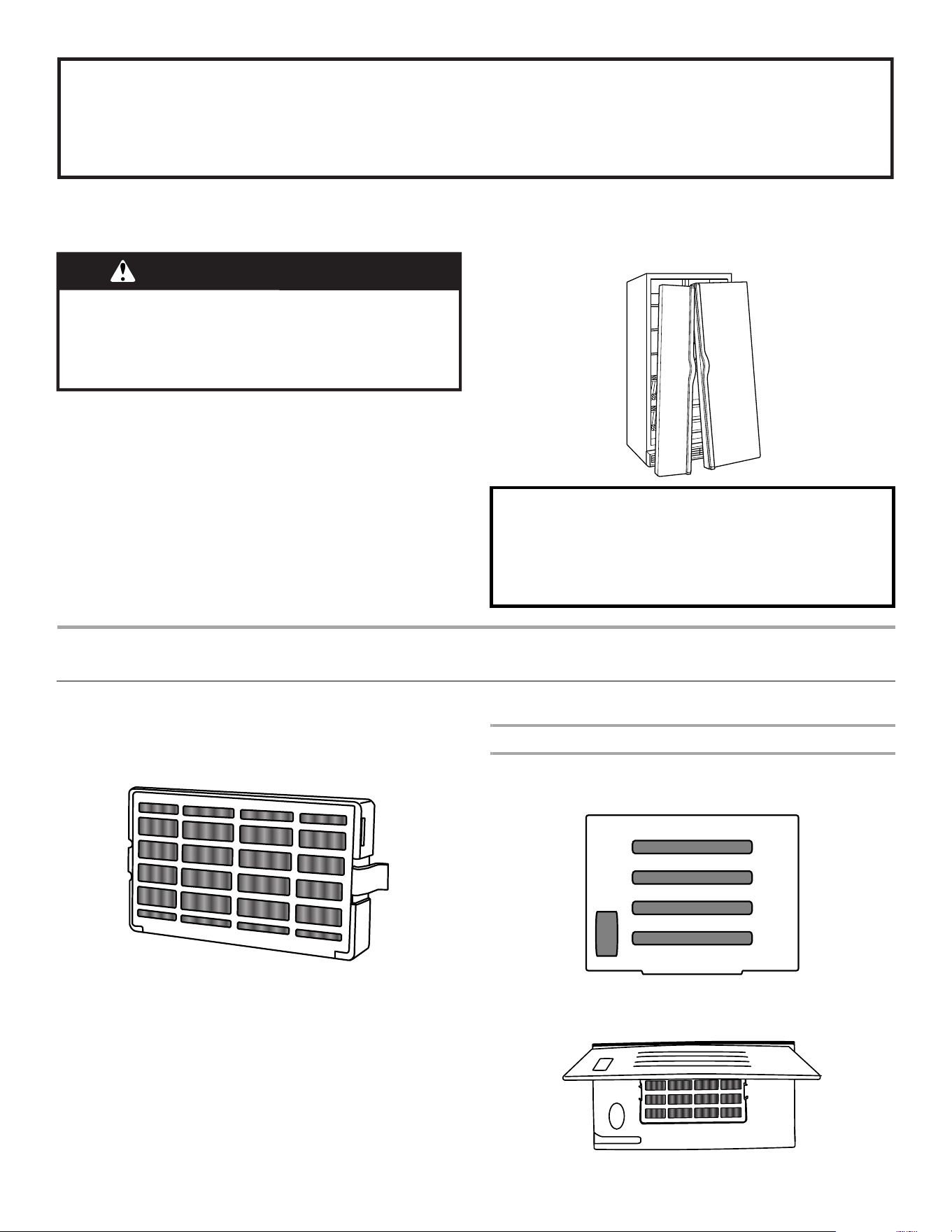
39
Mise au rebut appropriée
de votre vieux réfrigérateur
IMPORTANT : L'emprisonnement et l'étouffement des enfants ne
sont pas un problème du passé. Les réfrigérateurs jetés ou
abandonnés sont encore dangereux, même s'ils sont laissés
abandonnés pendant “quelques jours seulement”. Si vous vous
débarrassez de votre vieux réfrigérateur, veuillez suivre les
instructions suivantes pour aider à éviter les accidents.
Avant de jeter votre vieux réfrigérateur ou congélateur :
■ Enlever les portes.
■ Laisser les tablettes en place de sorte que les enfants ne
puissent pas y pénétrer facilement.
UTILISATION DU RÉFRIGÉRATEUR
Installation du filtre à air (sur certains modèles)
Sur certains modèles, le sachet d’accessoires du réfrigérateur
comprend un filtre à air qui doit être installé avant d’utiliser le
réfrigérateur. Sur certains modèles, le filtre à air est préinstallé à
l’usine.
Le filtre à air réduit l'accumulation d'odeurs. Ceci aide à maintenir
un environnement plus propre à l’intérieur du réfrigérateur.
Installation du filtre à air (sur certains modèles)
Le filtre doit être installé derrière la porte à aérations, située (selon
le modèle) le long de la paroi intérieure gauche ou arrière, à
proximité du sommet du compartiment de réfrigération.
1. Retirer le filtre à air de son emballage.
2. Ouvrir la porte à aérations en la soulevant.
3. Emboîter le filtre pour le mettre en place.
4. Fermer la porte à aérations.
Avertissements de la proposition 65 de l'État de Californie :
AVERTISSEMENT : Ce produit contient au moins un produit chimique connu par l’État de Californie pour être à l’origine de
cancers.
AVERTISSEMENT : Ce produit contient au moins un produit chimique connu par l’État de Californie pour être à l’origine de
malformations et autres déficiences de naissance.
AVERTISSEMENT
Risque de suffoquer
Enlever les portes de votre vieux réfrigérateur.
Le non-respect de cette instruction peut causer
un décès ou des lésions cérébrales.
Renseignements importants à propos de la mise au
rebut des fluides réfrigérants :
Mettre le réfrigérateur au rebut conformément à la
réglementation fédérale et locale. Les fluides réfrigérants
doivent être évacués par un technicien certifié et agréé par
l’EPA conformément aux procédures établies.
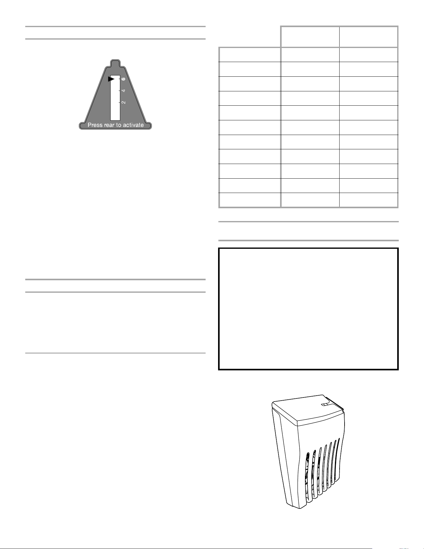
40
Installation du témoin de statut de filtre (sur certains modèles)
Le filtre comporte un témoin de statut qui doit être activé et
installé en même temps que le filtre à air.
1. Placer le témoin orienté vers le bas sur une surface ferme et
plane.
2. Appliquer une pression sur la bulle située à l’arrière du témoin
jusqu’à ce que la bulle éclate – ceci active le témoin.
3. Ouvrir la porte du filtre à air à aérations en la soulevant. Sur
certains modèles, l’arrière de la porte comporte des
encoches.
4. Modèles avec encoches :
■ Faire glisser le témoin vers le bas, dans les encoches, en
l’orientant vers l’extérieur.
REMARQUE : Le témoin ne glissera pas facilement dans
les encoches si la bulle arrière n'a pas éclaté.
■ Fermer la porte du filtre à air et vérifier que le témoin est
visible à travers le trou rectangulaire de la porte.
Modèles sans encoches :
■ Conserver le témoin dans un endroit visible dont
l'utilisateur se souviendra facilement - soit à l'intérieur du
réfrigérateur, soit dans un autre endroit de la cuisine ou du
domicile.
Remplacement du filtre à air
Le filtre à air jetable doit être remplacé tous les 6 mois, lorsque le
témoin de statut est entièrement passé du blanc au rouge.
Pour commander un filtre à air de rechange, voir “Accessoires”.
1. Retirer l’ancien filtre à air en serrant les onglets latéraux.
2. Retirer l’ancien témoin de statut.
3. Installer le filtre à air et le témoin de statut neufs à l'aide des
instructions des sections précédentes.
Installation du sachet de conservation
pour produits frais
(sur certains modèles)
Sur certains modèles, le sachet d’accessoires du réfrigérateur
comprend un sachet de conservation pour produits frais, qui doit
être installé avant d’utiliser le réfrigérateur. Sur certains modèles,
le sachet de conservation pour produits frais est préinstallé à
l’usine.
Le sachet de conservation pour produits frais absorbe l'éthylène,
permettant ainsi un ralentissement du processus de maturation
de nombreux produits frais. Ainsi, la fraîcheur de certains produits
frais est prolongée.
La production d'éthylène et la sensibilité des produits à l'éthylène
varie selon le type de fruit ou de légume. Afin de préserver la
fraîcheur des aliments, il est préférable de séparer les produits
frais sensibles à l'éthylène des fruits produisant des quantités
d'éthylène modérées à élevées.
Installation du sachet de conservation pour produits frais
(sur certains modèles)
Les sachets de conservation pour produits frais doivent être
installés dans leur logement, situé le long d’une paroi latérale
interne du bac à légumes ou du tiroir convertible.
MONTHS
REPLACE
Sensibilité à
l'éthylène
Production
d'éthylène
Pommes Élevée Très élevée
Asperges Moy. Très basse
Baies Basse Basse
Brocoli Élevée Très basse
Melon brodé Moy. Élevée
Carottes Basse Très basse
Agrumes Moy. Très basse
Raisin Basse Très basse
Laitue Élevée Très basse
Poires Élevée Très élevée
Épinards Élevée Très basse
ATTENTION : IRRITANT
PEUT IRRITER LES YEUX ET LA PEAU. DÉGAGE DES
ÉMANATIONS DANGEREUSES LORSQUE MÉLANGÉ
AVEC D’AUTRES PRODUITS.
Ne pas mélanger avec d’autres agents de nettoyage tels
que l’ammoniaque, un agent de blanchiment ou des
acides. Éviter tout contact avec les yeux, la peau ou les
vêtements. Ne pas respirer les poussières. Tenir hors de la
portée des enfants.
PREMIERS SOINS : Contient du permanganate de
potassium. En cas d’ingestion, appeler immédiatement un
centre antipoison ou un médecin. Ne pas provoquer le
vomissement. En cas de contact avec les yeux, rincer avec
de l’eau pendant 15 minutes. En cas de contact avec la
peau, bien rincer avec de l’eau.
CAUTION
IR
R
ITA
N
T
Read cautions on back.
ATTENTION
IR
R
ITA
N
T
Lisez des prudences sur le revers.
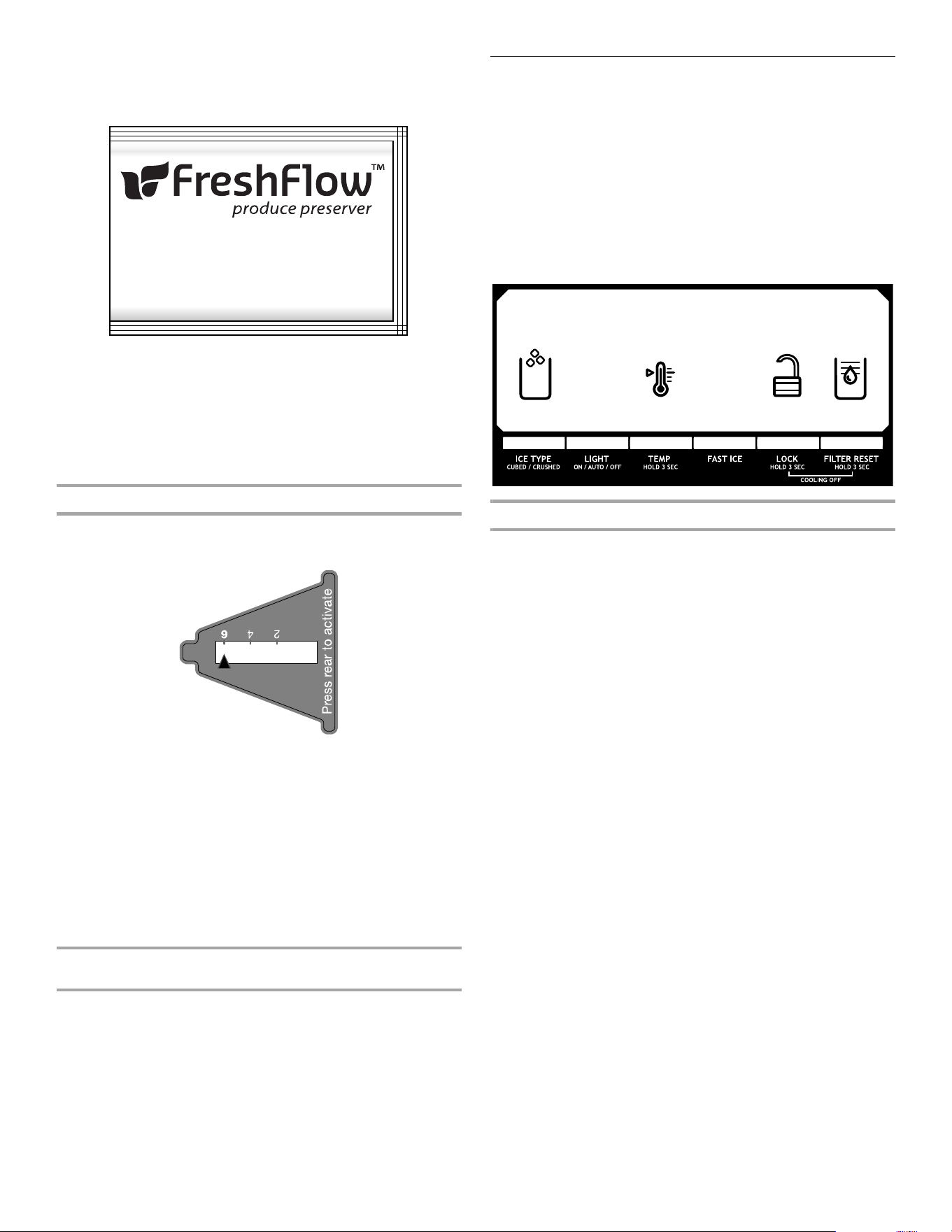
41
REMARQUE : Pour une performance idéale, toujours utiliser les
deux sachets.
1. Retirer les sachets de conservation pour produits frais de leur
emballage.
2. Soulever le logement pour l’extraire de la languette de
montage le long de la paroi.
3. Ouvrir le logement en soulevant l’arrière du sommet du
logement pour l'extraire.
4. Placer les deux sachets à l’intérieur du logement puis
emboîter les deux parties du logement pour le refermer.
5. Réinstaller le logement sur la languette de montage le long de
la paroi.
Installation du témoin de statut (sur certains modèles)
Le sachet de conservation pour produits frais comporte un témoin
de statut qui doit être activé et installé en même temps que le
sachet.
1. Orienter le témoin vers le bas en le plaçant sur une surface
ferme et plane.
2. Appliquer une pression sur la bulle située à l’arrière du témoin
jusqu’à ce que la bulle éclate – ceci active le témoin.
3. Ouvrir le couvercle du logement du sachet de conservation
pour produits frais.
4. Placer le témoin sur le sommet du logement en l’orientant vers
l'extérieur.
5. Fermer le couvercle en le faisant coulisser et vérifier que le
témoin est visible à travers le trou rectangulaire du couvercle.
REMARQUE : Le couvercle ne se fermera pas facilement si la
bulle arrière du témoin de statut n'a pas éclaté.
Remplacement du sachet de conservation pour produits frais
(sur certains modèles)
Les sachets jetables doivent être remplacés tous les 6 mois,
lorsque le témoin est entièrement passé du blanc au rouge.
Pour commander des sachets de rechange, voir “Accessoires”.
1. Retirer les anciens sachets du logement du conservateur pour
produits frais.
2. Retirer l’ancien témoin.
3. Installer les sachets et le témoin neufs en suivant les
instructions des sections précédentes.
Utilisation des commandes
Les commandes du réfrigérateur et du congélateur se trouvent sur
le tableau de distribution.
IMPORTANT : L’écran d’affichage sur le tableau de commande
du distributeur s’éteint automatiquement et entre au mode “veille”
lorsque les boutons de commande et les plaques de distribution
n’ont pas été utilisés pendant au moins 2 minutes. Le fait
d’appuyer une fois sur un bouton de commande au mode “veille”
réactive uniquement l’écran d’affichage, sans modifier les
réglages.
■ Appuyer sur n’importe quel bouton de commande sur le
tableau de distribution pour activer l'écran d’affichage.
L’écran d’accueil apparaît tel qu’indiqué.
Ajustement des commandes
Pour votre confort, les commandes du réfrigérateur et du
congélateur sont préréglées à l’usine. Lors de l’installation initiale
du réfrigérateur, s’assurer que les commandes sont encore
préréglées au “réglage moyen”. Les points de réglage
recommandés par l’usine sont 37°F (3°C) pour le réfrigérateur et
0°F (-18°C) pour le congélateur.
IMPORTANT :
■ Attendre 24 heures avant d’ajouter des aliments dans le
réfrigérateur. Si on ajoute des aliments alors que le
réfrigérateur n’a pas complètement refroidi, les aliments
risquent de s’abîmer.
REMARQUE : Ajuster la commande sur un réglage plus froid
que celui qui est recommandé ne refroidira pas les
compartiments plus rapidement.
■ Si la température est trop tiède ou trop froide dans le
réfrigérateur ou le congélateur, vérifier d’abord les évents pour
s’assurer qu’ils ne sont pas bloqués, avant de régler les
commandes.
■ Les réglages préréglés devraient être corrects pour l’utilisation
domestique normale. Les réglages sont faits correctement
lorsque le lait ou le jus sont aussi froids que vous l’aimez et
lorsque la crème glacée est ferme.
■ Attendre au moins 24 heures entre les ajustements. Vérifier de
nouveau les températures avant de procéder à d’autres
ajustements.
Pour visualiser et ajuster les points de réglage, appuyer pendant
3 secondes sur la touche TEMP (température). Lorsque le mode
de réglage est activé, les données d’ajustement apparaissent sur
l’écran d’affichage.
CAUTION
IRRITANT
Read cautions on back.
ATTENTION
IRRITANT
Lire les mises en garde au dos.
Whirlpool Corporation, Benton Harbor MI 49022
MONTHS
REPLACE
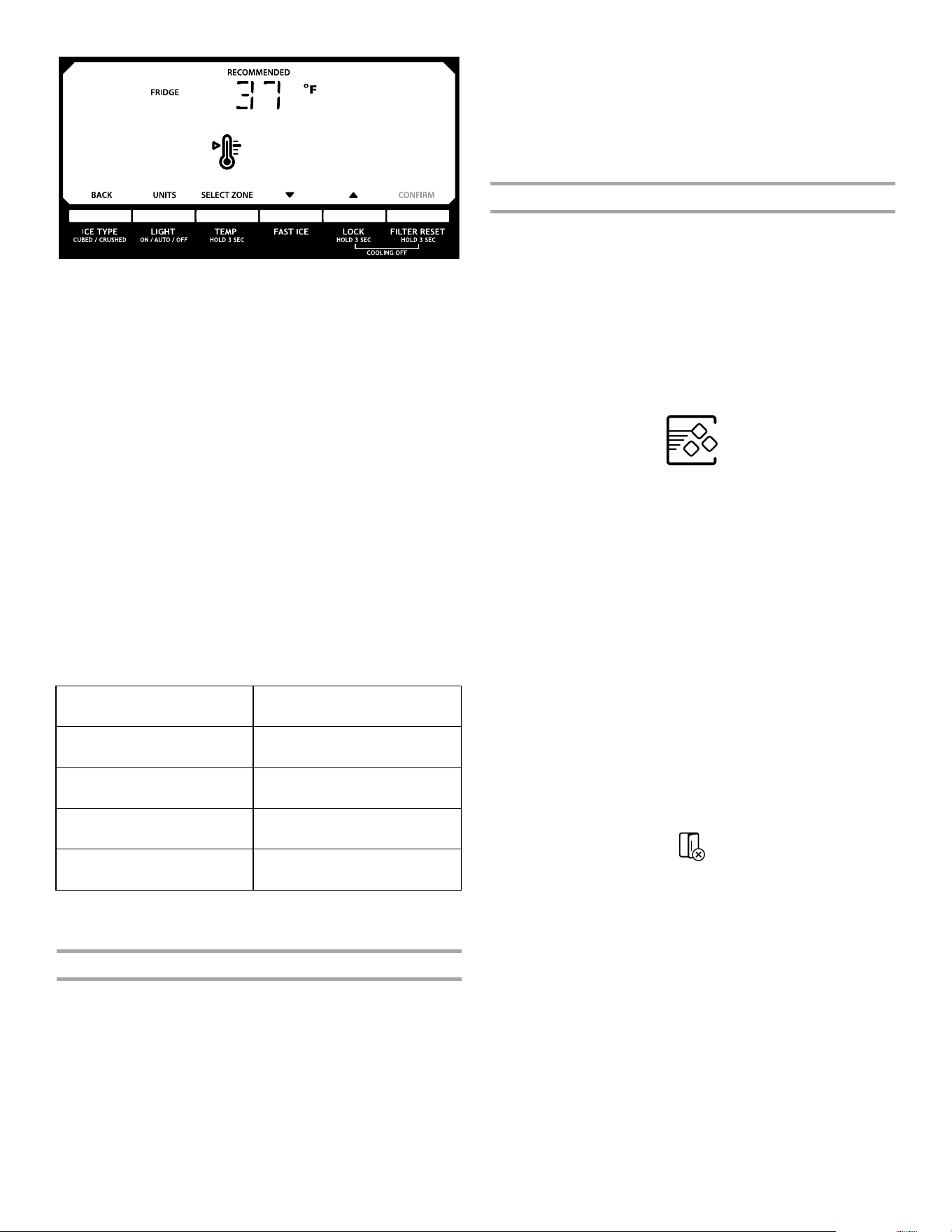
42
REMARQUE : Pour visualiser les températures en Celsius,
appuyer sur la touche LIGHT (éclairage) lorsque le mode de
réglage est activé. Pour revenir au mode d’affichage en
Fahrenheit, appuyer de nouveau sur LIGHT.
■ Lorsque le mode de réglage est activé, l’écran d’affichage
indique le point de réglage du réfrigérateur et “FRIDGE”
(réfrigérateur) apparaît.
■ Appuyer sur LOCK (verrouillage) pour augmenter le point de
réglage, ou sur FAST ICE (glace rapide) pour le réduire.
■ Après avoir fini de visualiser (et d’ajuster, si désiré) le point de
réglage du réfrigérateur, appuyer sur TEMP (température) pour
modifier l’affichage et faire apparaître le point de réglage du
congélateur. Une fois le changement de zone effectué,
“FREEZER” (congélateur) apparaît sur l’écran d’affichage.
■ Appuyer sur LOCK (verrouillage) pour augmenter le point de
réglage, ou sur FAST ICE pour le réduire.
■ Après avoir fini de visualiser (et d’ajuster, si désiré) les points
de réglage du réfrigérateur et du congélateur, appuyer sur
FILTER (filtre) pour sauvegarder les réglages.
REMARQUE : Pour sortir sans sauvegarder les modifications,
appuyer sur ICE TYPE (type de glace) à tout moment à partir
du mode de réglage ou laisser 60 secondes d’inactivité
s’écouler; le mode de réglage s’éteindra automatiquement.
Pour ajuster les points de réglage de température, utiliser le
tableau suivant comme guide.
La gamme de valeurs de réglage pour le réfrigérateur va de 33°F à
45°F (0°C à 7°C). La gamme de valeurs de réglage pour le
congélateur va de -5°F à 5°F (-21°C à -15°C).
Refroidissement On/Off (marche/arrêt)
Ni le réfrigérateur, ni le congélateur ne refroidiront lorsque le
refroidissement est désactivé.
■ Pour désactiver le refroidissement, appuyer simultanément
sur les boutons LOCK (verrouillage) et FILTER (filtre) pendant
3 secondes.
IMPORTANT : Afin d’éviter de verrouiller le distributeur ou de
modifier des réglages involontairement, veiller à appuyer sur
les deux boutons exactement au même moment.
Lorsque le refroidissement est désactivé, “COOLING OFF”
(refroidissement désactivé) apparaît sur l’écran d’affichage.
■ Appuyer de nouveau pendant 3 secondes sur LOCK
(verrouillage) et FILTER (filtre) pour réactiver le refroidissement.
Caractéristiques supplémentaires
Fast Ice (glace rapide)
La caractéristique Fast Ice est utile lors de périodes temporaires
d'utilisation intense de glaçons en augmentant la production de
glaçons sur une période de 24 heures.
IMPORTANT : Cette caractéristique ne fonctionne que si la
machine à glaçons est en marche. Voir “Machine à glaçons et bac
d’entreposage”.
■ Appuyer sur la touche FAST ICE pour activer la caractéristique
de glace rapide. Lorsque cette caractéristique est activée,
l’icône “Fast Ice” apparaît sur l’écran d’affichage du
distributeur. Le réglage Fast Ice demeure activé pendant
24 heures à moins d’être annulé manuellement.
■ Pour désactiver manuellement la caractéristique Fast Ice,
appuyer de nouveau sur FAST ICE ou ajuster le point de
réglage de température du congélateur. L’icône Fast Ice
disparaît lorsque cette caractéristique est désactivée.
REMARQUE : Si l’on désire une production accrue de glaçons en
permanence, placer le point de réglage du congélateur à un
réglage inférieur. Le réglage du congélateur à une température
plus froide peut rendre certains aliments, comme la crème glacée,
plus durs.
Alarme de porte entrouverte
La caractéristique d'alarme de porte entrouverte fait entendre un
signal d'alarme lorsque la porte du réfrigérateur ou du congélateur
est ouverte pendant 5 minutes et que le système de
refroidissement fonctionne. L’alarme retentira toutes les
2 minutes. Fermer les deux portes pour l’arrêter. La
caractéristique se réinitialise ensuite et se réactive si l’une des
deux portes est de nouveau laissée ouverte pendant 5 minutes.
REMARQUE : Pour que l’alarme sonore cesse de retentir tout en
gardant les portes ouvertes, comme lors du nettoyage de
l’intérieur du réfrigérateur, appuyer sur n’importe quel bouton sur
le tableau de commande. Le son de l’alarme sera temporairement
supprimé, mais l’icône de porte entrouverte restera affichée sur le
tableau de commande du distributeur.
Évaporateur double (sur certains modèles)
Certains modèles sont équipés d’un double système
d’évaporation séquentiel, composé de deux évaporateurs
distincts pour les compartiments de réfrigération et de
congélation.
La double évaporation engendre un taux d’humidité supérieur, qui
contribue à ralentir la détérioration des aliments dans le
réfrigérateur et à améliorer leur qualité et leur fraîcheur dans le
congélateur en raison d’une brûlure de congélation moins vive.
En outre, le double système d’évaporation contribue à éviter que
les odeurs de nourriture présentes dans le réfrigérateur ne se
transfèrent à la glace du congélateur.
REMARQUE : Le double système d’évaporation est toujours
activé lorsque le réfrigérateur fonctionne. Il n’est pas nécessaire
d’appuyer sur un quelconque bouton pour l’activer.
CONDITION : AJUSTEMENT DE LA
TEMPÉRATURE :
RÉFRIGÉRATEUR trop froid Réglage du RÉFRIGÉRATEUR
1° plus haut
RÉFRIGÉRATEUR trop tiède Réglage du RÉFRIGÉRATEUR
1° plus bas
CONGÉLATEUR trop froid Réglage du CONGÉLATEUR
1° plus haut
CONGÉLATEUR trop tiède /
Trop peu de glaçons
Réglage du CONGÉLATEUR
1° plus bas
43
Commande de température dans
le tiroir convertible
(sur certains modèles)
La commande peut être ajustée pour un refroidissement
approprié des viandes ou des légumes. L’air à l’intérieur du
contenant est refroidi pour éviter les "petits espaces" de
congélation et peut être réglé pour garder les viandes aux
températures de conservation de 28° à 32°F (de -2° à 0°C)
recommandées par l’Office national du bétail et des viandes.
Conservation de la viande :
Régler la commande sur l'un des trois réglages MEAT (viande)
pour conserver la viande à sa température de conservation
optimale.
Conservation des légumes :
Régler la commande à VEG (légumes) pour conserver les légumes
à leurs températures de conservation optimales.
REMARQUE : Si les aliments commencent à geler, déplacer la
commande vers la droite (moins froid) en l’orientant vers le
réglage VEG (légumes). Ne pas oublier d'attendre 24 heures entre
les ajustements.
Réglage de l'humidité dans
le bac à légumes
(sur certains modèles)
On peut contrôler le degré d'humidité dans le bac à légumes
étanche. La commande peut être ajustée à n'importe quel réglage
entre LOW et HIGH.
LOW/bas (ouvert) pour une meilleure conservation des fruits et
légumes à pelures.
HIGH/haut (fermé) pour une meilleure conservation des légumes à
feuilles frais.
Compartiment fraîcheur dans la porte
(sur certains modèles)
De l'air froid du congélateur passe directement dans le
compartiment de la porte du réfrigérateur situé sous les évents.
REMARQUE : Le compartiment à produits laitiers et le porte-
canettes ne sont pas associés à la caractéristique Compartiment
fraîcheur dans la porte.
Commande du compartiment fraîcheur dans la porte
La commande du compartiment fraîcheur se trouve sur le côté
gauche du compartiment de réfrigération.
■ Déplacer le bouton de commande du compartiment fraîcheur
vers la gauche pour réduire la circulation d'air froid dans le
compartiment et le rendre ainsi moins froid.
■ Déplacer le bouton de commande du compartiment fraîcheur
vers la droite pour augmenter la circulation d'air froid dans le
compartiment et le rendre ainsi plus froid.
Distributeurs d’eau et de glaçons
REMARQUES :
■ Le système de distribution ne fonctionne pas lorsque la porte
du réfrigérateur ou du congélateur est ouverte.
■ Accorder 24 heures pour que le réfrigérateur se refroidisse et
refroidisse l'eau.
■ Accorder 24 heures pour produire la première quantité de
glaçons. Jeter les trois premières quantités de glaçons
produites. Attendre 72 heures pour une production complète
de glaçons.
■ L’écran d’affichage sur le tableau de commande du
distributeur s’éteint automatiquement et entre au mode
“veille” lorsque les boutons de commande et les plaques de
distribution n’ont pas été utilisés pendant au moins 2 minutes.
Le fait d’appuyer une fois sur un bouton de commande au
mode “veille” réactive uniquement l’écran d’affichage, sans
modifier les réglages.
Rinçage du circuit d’eau
De l’air piégé dans le système de distribution d'eau peut faire
goutter le distributeur d'eau. Après avoir raccordé le réfrigérateur
à une source d’alimentation en eau ou remplacé le filtre à eau,
vidanger le circuit d’eau. Le fait de rincer le système de
distribution d'eau évacue l'air de la canalisation et du filtre, et
conditionne le filtre à eau.
REMARQUE : Pendant l'évacuation de l'air, de l'eau peut gicler
du distributeur.
1. Utiliser un récipient robuste pour appuyer sur la plaque du
distributeur d’eau pendant 5 secondes, puis relâcher la
plaque pendant 5 secondes.
2. Répéter l’étape 1 jusqu’à ce que l’eau commence à couler.
3. Une fois que l’eau commence à couler, continuer d'appuyer
puis de relâcher la plaque du distributeur (appui pendant
5 secondes, relâchement pendant 5 secondes) jusqu’à ce
qu’un total de 3 gal. (12 L) soit distribué.
Une vidange supplémentaire peut être nécessaire dans certains
domiciles.
Le distributeur d'eau
IMPORTANT :
■ Distribuer au moins 1 pte (1 L) d’eau chaque semaine pour
maintenir un approvisionnement en eau fraîche.
■ Si le débit en provenance du distributeur diminue, cela peut
être dû à une faible pression en eau.
■ Avec le filtre à eau retiré, verser l’équivalent d’une (1) tasse
(237 mL) d’eau. Si l’équivalent d’une (1) tasse d’eau est
distribué en 8 secondes ou moins, cela signifie que la
pression en eau alimentant le réfrigérateur répond au
critère minimal.
■ S’il faut plus de 8 secondes à la machine pour distribuer
l’équivalent d’une (1) tasse d’eau, cela signifie que la
pression en eau alimentant le réfrigérateur est inférieure au
niveau recommandé. Voir “Spécifications de l’alimentation
en eau” ou “Dépannage” ou “Résolution de problèmes”
pour des suggestions sur la marche à suivre.
A. Commande du compartiment fraîcheur dans la porte
A
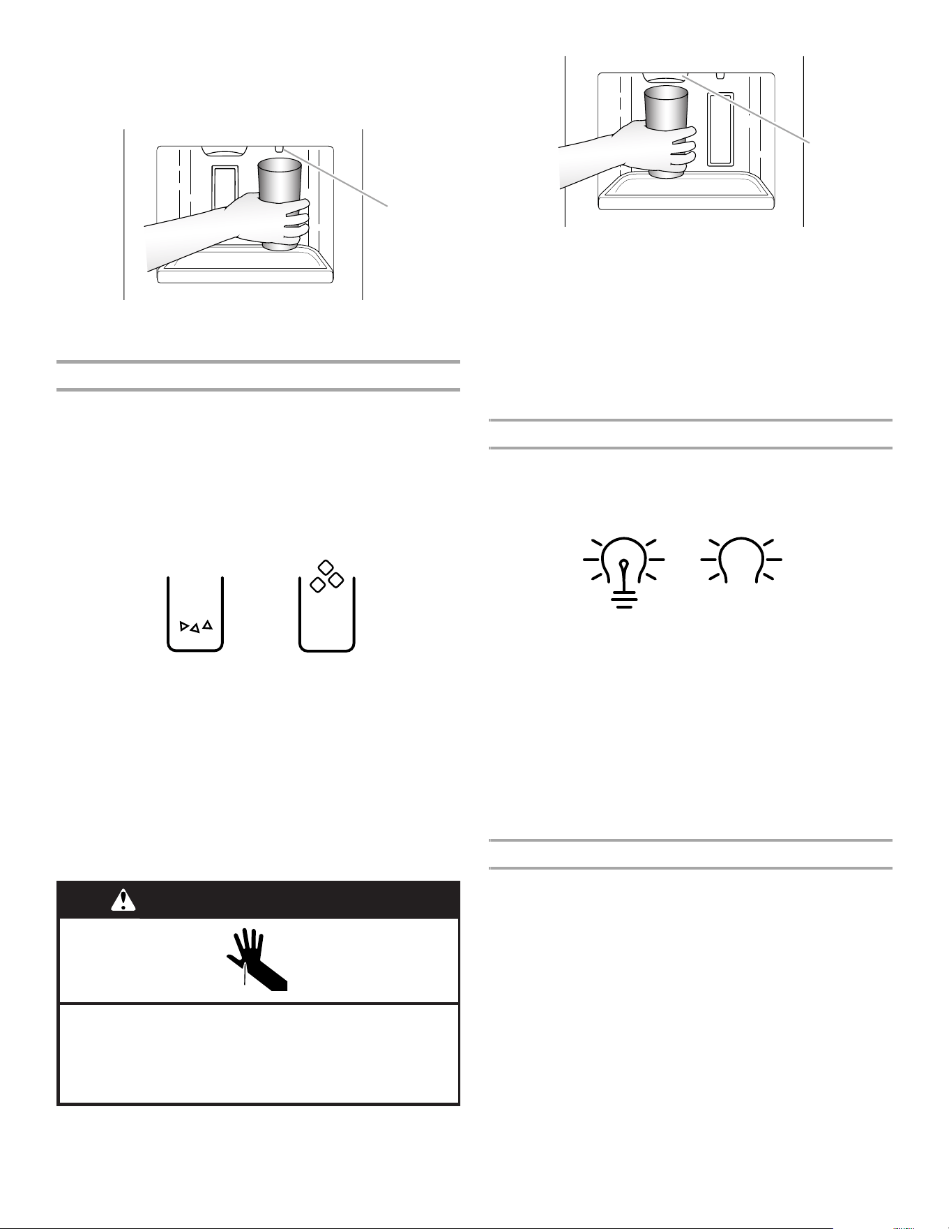
44
Distribution d’eau :
1. Appuyer un verre robuste contre la plaque du distributeur
d’eau. Tenir le verre près de la canule du distributeur d’eau
pour que l'eau coule dans le verre.
2. Retirer le verre pour arrêter la distribution.
Le distributeur de glaçons
La glace tombe du bac d'entreposage de la machine à glaçons
dans le congélateur lorsqu'on appuie sur la plaque du distributeur.
Pour éteindre la machine à glaçons, voir “Machine à glaçons et
bac d'entreposage”.
La machine à glaçons peut produire à la fois de la glace
concassée et des glaçons. Avant toute distribution de glace,
sélectionner le type de glace préféré avec le bouton ICE TYPE
(typedeglace).
L’écran d’affichage indique le type de glace sélectionné.
Pour de la glace concassée, les glaçons sont concassés avant
d'être distribués. Cette action peut causer un court délai lors de la
distribution de glace concassée. Le bruit du broyeur de glaçons
est normal et la dimension des morceaux de glace peut varier.
Lorsqu'on passe du mode glace concassée au mode glaçons,
quelques onces de glace concassée sont distribuées avec les
premiers glaçons.
Distribution de glace :
1. S'assurer que le type de glaçons désiré est bien sélectionné.
Pour passer de glaçons à glace concassée, appuyer sur
ICE TYPE (type de glace).
2. Appuyer un verre robuste contre la plaque de distribution de
glaçons. Tenir le verre près de la goulotte à glaçons pour que
les glaçons tombent dans le verre.
IMPORTANT : Il n'est pas nécessaire d'exercer une pression
importante sur la plaque pour activer le distributeur de
glaçons. Une pression forte ne donne pas une distribution
plus rapide de glaçons ou des quantités plus grandes.
3. Retirer le verre pour arrêter la distribution.
REMARQUE : La distribution de glaçons peut se poursuivre
jusqu'à quelques secondes après que le verre a été éloigné de
la plaque. Le distributeur peut continuer à faire du bruit
pendant quelques secondes après la distribution.
La lampe du distributeur
Lorsqu'on utilise le distributeur, la lampe s'allume
automatiquement. Pour avoir la lumière allumée en permanence,
sélectionner ON ou DIM. L’écran d’affichage indique le mode
sélectionné.
ON (marche) : Appuyer sur LIGHT (lumière) pour allumer la lampe
du distributeur.
DIM (faible luminosité) : Appuyer sur LIGHT une deuxième fois
pour sélectionner le mode DIM. La lampe du distributeur restera
allumée, mais à une intensité plus faible.
OFF (arrêt) : Appuyer sur LIGHT une troisième fois pour éteindre
la lampe du distributeur.
Les lampes du distributeur sont des DEL qui ne peuvent pas être
remplacées. Si les lampes du distributeur ne fonctionnent pas,
voir la section “Dépannage” ou “Résolution de problèmes” pour
plus d'informations.
Le verrouillage du distributeur
Le distributeur peut être verrouillé pour un nettoyage facile ou
pour éviter la distribution involontaire par de jeunes enfants ou
des animaux de compagnie.
REMARQUE : La caractéristique de verrouillage ne coupe pas le
courant électrique au réfrigérateur, à la machine à glaçons ou à la
lumière du distributeur. Cela désactive tout simplement les
commandes et les plaques du distributeur. Pour éteindre la
machine à glaçons, voir “Machine à glaçons et bac
d'entreposage”.
■ Appuyer sur LOCK pendant 3 secondes pour verrouiller le
distributeur.
■ Appuyer à nouveau sur LOCK pour déverrouiller le
distributeur.
A. Canule du distributeur d’eau
CRUSHED
(Glace concassée)
CUBED
(Glaçons)
A
Risque de coupure
Utiliser un verre robuste pour prendre des glaçons.
Le non-respect de cette instruction peut causer
des coupures.
AVERTISSEMENT
A. Goulotte à glaçons
ON
(Marche)
DIM
(Faible luminosité)
A
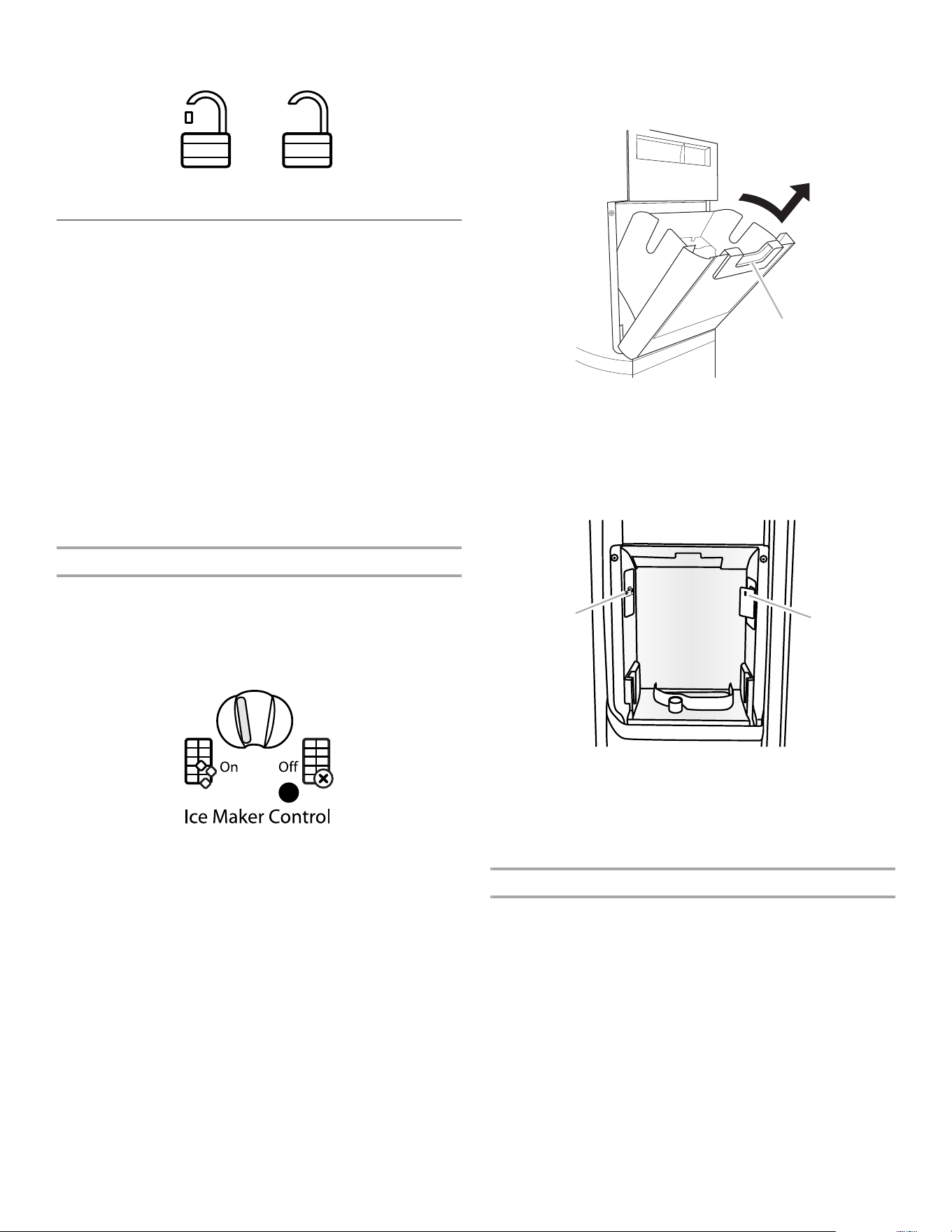
45
L’écran d’affichage indique si le distributeur est verrouillé.
Machine à glaçons et bac
d'entreposage
■ Accorder 24 heures pour produire la première quantité de
glaçons. Jeter les trois premières quantités de glaçons
produites.
■ La qualité de vos glaçons dépend de la qualité de l'eau fournie
à votre machine à glaçons. Éviter de brancher la machine à
glaçons à un approvisionnement d'eau adoucie. Les produits
chimiques adoucisseurs d'eau (tels que le sel) peuvent
endommager des pièces de la machine à glaçons et causer
une piètre qualité des glaçons. Si une alimentation d'eau
adoucie ne peut pas être évitée, s'assurer que l'adoucisseur
d'eau fonctionne bien et qu'il est bien entretenu.
■ Ne pas utiliser un objet pointu pour briser les glaçons dans le
bac d'entreposage. Cette action peut endommager le bac et
le mécanisme du distributeur.
■ Ne pas garder quoi que ce soit sur le dessus ou dans la
machine à glaçons ou dans le bac à glaçons.
Style 1
Mise en marche/arrêt de la machine à glaçons :
On ne peut accéder au commutateur marche/arrêt qu’une fois le
bac d’entreposage à glaçons retiré. Le commutateur se trouve
sur la porte du congélateur, du côté gauche de la paroi entourant
le bac d’entreposage à glaçons. Voir la section suivante pour des
instructions sur le retrait du bac.
■ Pour mettre en marche la machine à glaçons, glisser le
commutateur vers la position ON (vers la gauche).
■ Pour arrêter manuellement la machine à glaçons, glisser le
commutateur vers la position OFF (vers la droite).
REMARQUE : La machine à glaçons comporte un système
d’arrêt automatique pour éviter le débordement du bac
d’entreposage dans les conditions normales de fonctionnement.
Les détecteurs de la machine à glaçons arrêteront
automatiquement la production de glaçons mais le commutateur
restera en position ON (vers la gauche).
Pour retirer et réinstaller le bac à glaçons :
1. Appuyer sur le levier de dégagement et incliner le seau vers
l'extérieur. Saisir la base du bac d’entreposage à deux mains
et le soulever pour le dégager.
REMARQUE : Il n'est pas nécessaire de pousser le
commutateur de la machine à glaçons vers la position OFF
(vers la droite) lorsqu'on enlève le bac. Le couvercle du
détecteur (“porte à clapet”) sur la paroi de droite de la porte
du congélateur interrompt la production de glaçons lorsque la
porte est ouverte ou que le bac d’entreposage a été enlevé.
2. Réinstaller le bac en le faisant glisser sur la porte puis en
l’inclinant vers l’arrière et en le plaçant en position verticale.
Le levier de dégagement émet un déclic lorsque le bac est
bien en place.
Style 2
Mise en marche/arrêt de la machine à glaçons :
■ Pour mettre la machine à glaçons en marche, il suffit
d'abaisser le bras de commande en broche.
■ Pour arrêter manuellement la machine à glaçons, soulever le
bras de commande en broche à la position OFF (élevée) et
attendre le clic. Les glaçons peuvent encore être distribués,
mais aucun autre glaçon ne peut être fait.
REMARQUE : La machine à glaçons comporte un système
d’arrêt automatique pour éviter le débordement du bac
d’entreposage dans les conditions normales de fonctionnement.
Au fur et à mesure de la fabrication de la glace, les glaçons
remplissent le bac d'entreposage de glaçons. Les glaçons
soulèvent le bras de commande en broche à la position OFF
(élevée). Ne pas forcer le bras de commande en broche vers le
haut ou vers le bas.
LOCKED
(Verrouillé)
UNLOCKED
(Déverrouillé)
A. Levier de dégagement
A. Commutateur marche/arrêt
B. Couvercle du détecteur
A
B
A
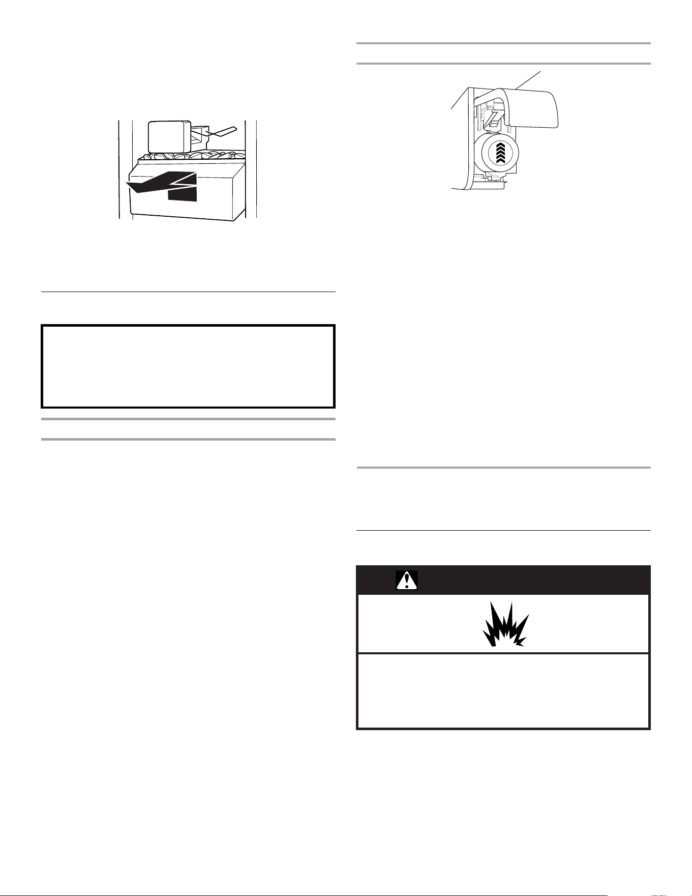
46
Pour retirer et réinstaller le bac à glaçons :
1. Tirer le panneau qui recouvre le bac à glaçons en le retirant
hors de la base.
2. Soulever le bras en broche jusqu’à ce qu’il s’enclenche à la
position OFF (élevée).
3. Soulever le devant du bac à glaçons et le retirer.
4. Replacer le bac à glaçons en le poussant complètement sinon
le distributeur ne fonctionnera pas.
5. Pour remettre la production de glaçons en marche, appuyer
sur le bras en broche pour l’abaisser à la position ON.
S’assurer que la porte est bien fermée.
Système de filtration de l'eau
Témoin lumineux de l'état du filtre à eau
Le témoin lumineux de l'état du filtre à eau vous permettra de
savoir quand changer votre filtre à eau.
■ Lorsque l’affichage du témoin du filtre à eau sur le tableau de
commande passe à “ORDER” (commander), ceci indique qu’il
est presque temps de changer la cartouche du filtre à eau.
■ Remplacer la cartouche du filtre à eau lorsque l’écran
d’affichage indique “REPLACE” (remplacer).
REMARQUE : Si le débit d’eau vers le distributeur d’eau ou la
machine à glaçons décroît de manière sensible, il convient de
changer le filtre plus tôt. Le filtre doit être remplacé au moins
tous les 6 mois selon la qualité de l’eau et la fréquence
d'utilisation.
Réinitialisation de l’état du filtre
■ Après avoir changé le filtre à eau, régler de nouveau le témoin
lumineux du filtre à eau en appuyant sur FILTER (filtre)
pendant 3 secondes.
Une fois le système réinitialisé, les icônes “ORDER”
(commander) et “REPLACE” (remplacer) disparaissent de
l’écran d’affichage.
Remplacement du filtre à eau
1. Repérer le filtre à eau situé dans le coin supérieur droit du
compartiment de réfrigération.
2. Ouvrir la porte du couvercle du filtre en la soulevant. Le filtre
est libéré puis éjecté lorsqu’on ouvre la porte.
3. Une fois la porte complètement ouverte, retirer le filtre en le
tirant en ligne droite.
REMARQUE : Il y aura peut-être de l’eau dans le filtre. Il est
possible que de l'eau se renverse. Utiliser une serviette pour
essuyer tout renversement.
4. Retirer le filtre neuf de son emballage, puis retirer les
protections des anneaux d'étanchéité. S'assurer que les
anneaux d'étanchéité sont toujours en place une fois que les
couvercles sont retirés.
5. Avec la flèche orientée vers le haut, aligner le filtre neuf avec le
logement du filtre et le faire glisser pour le mettre en place. La
porte du couvercle du filtre entame un mouvement
automatique de fermeture à mesure que l’on insère le filtre
neuf.
6. Fermer complètement la porte du couvercle du filtre pour
emboîter le filtre et le mettre en place. Il faudra peut-être
appuyer fortement.
7. Purger le circuit d'eau. Voir “Distributeurs d'eau et de
glaçons”.
ENTRETIEN DU
RÉFRIGÉRATEUR
Nettoyage
Les sections de réfrigération et de congélation se dégivrent
automatiquement. Toutefois, nettoyer les deux sections environ
une fois par mois pour éviter une accumulation d'odeurs. Essuyer
les renversements immédiatement.
IMPORTANT : Comme l’air circule entre les deux sections, toutes
les odeurs formées dans une section seront transférées à l’autre.
Vous devez nettoyer à fond les deux sections pour éliminer les
odeurs. Pour éviter le transfert d'odeurs et l'assèchement des
aliments, envelopper ou recouvrir hermétiquement les aliments.
Ne pas utiliser pour le filtrage d'une eau
microbiologiquement polluée ou de qualité inconnue en
l'absence d'un dispositif de désinfection adéquat avant ou
après le système. Les systèmes certifiés pour la réduction
de kyste peuvent être utilisés pour l'eau désinfectée qui
peut contenir des kystes filtrables.
AVERTISSEMENT
Risque d'explosion
Utiliser un produit de nettoyage ininflammable.
Le non-respect de cette instruction peut causer un décès,
une explosion ou un incendie.

47
Nettoyage de votre réfrigérateur :
REMARQUE : Ne pas utiliser des nettoyants abrasifs ou
puissants tels que les nettoyants à vitre en atomiseurs, nettoyants
à récurer, liquides inflammables, cires nettoyantes, détergents
concentrés, eau de Javel ou nettoyants contenant du pétrole sur
les pièces en plastique, les garnitures intérieures et de portes ou
les joints de portes. Ne pas utiliser d'essuie-tout, tampons à
récurer ou autres outils de nettoyage puissants.
1. Débrancher le réfrigérateur ou déconnecter la source de
courant électrique.
2. Laver à la main, rincer et sécher les pièces amovibles et les
surfaces internes à fond. Utiliser une éponge propre ou un
linge doux et un détergent doux dans de l'eau tiède.
3. Laver les surfaces extérieures en acier inoxydable ou en métal
peint avec une éponge propre ou un linge doux et un
détergent doux dans de l'eau tiède.
4. Le condenseur n'a pas besoin d'être nettoyé souvent dans
des conditions de fonctionnement normales. Si
l'environnement est particulièrement graisseux, poussiéreux,
ou s'il y a des animaux domestiques dans la maison, le
condenseur devrait être nettoyé tous les deux ou trois mois
pour assurer une efficacité maximum.
Si vous avez besoin de nettoyer le condenseur :
■ Retirer la grille de la base. Voir les instructions “Dépose de
la porte”, soit dans les instructions d’utilisation ou les
instructions d’installation et le manuel d’utilisation, soit sur
la feuille d’instructions fournie séparément avec le
réfrigérateur.
■ Utiliser un aspirateur à brosse douce pour nettoyer la
grille, les endroits ouverts derrière la grille et la surface à
l'avant du condenseur.
■ Replacer la grille de la base lorsqu’on a terminé.
5. Brancher le réfrigérateur ou reconnecter la source de courant
électrique.
Lampes
Les lampes internes et les lampes du distributeur sont des DEL
qui ne peuvent pas être remplacées.
■ Si les lampes du distributeur semblent ne pas fonctionner
tel que décrit dans “Distributeurs d’eau et de glaçons” (dans
les instructions d’utilisation, le guide d’utilisation, ou le guide
d’utilisation et d’entretien) ou si les lampes internes ne
s’allument pas lorsqu’on ouvre une porte, appeler les numéros
fournis pour obtenir de l'aide ou un dépannage. Voir la page
de couverture ou la garantie pour savoir qui contacter.
Entretien avant les vacances ou
lors d’un déménagement
Vacances
Si vous choisissez de laisser le réfrigérateur en marche
pendant votre absence :
1. Consommer tous les aliments périssables et congeler les
autres.
2. Si le réfrigérateur comporte une machine à glaçons
automatique et qu'il est raccordé à la source
d'approvisionnement en eau du domicile, fermer la source
d'approvisionnement en eau du réfrigérateur. Des dommages
matériels peuvent survenir si l’alimentation en eau n’est pas
coupée.
3. Si votre machine à glaçons est automatique, éteindre la
machine à glaçons.
REMARQUE : Selon votre modèle, soulever le bras de
commande métallique à la position OFF (arrêt) (position
élevée) ou placer le commutateur sur OFF (arrêt) (à droite).
4. Vider le bac à glaçons.
Si vous choisissez d’arrêter le fonctionnement du
réfrigérateur avant votre départ :
1. Enlever tous les aliments du réfrigérateur.
2. Si votre réfrigérateur a une machine à glaçons automatique :
■ Fermer l’approvisionnement d’eau de la machine à
glaçons au moins une journée à l’avance.
■ Lorsque la dernière quantité de glaçons est distribuée,
soulever le bras de commande en broche à la position
OFF (arrêt) (position élevée) ou déplacer le commutateur à
la position OFF (arrêt) (à droite).
3. Selon le modèle, tourner la commande du réfrigérateur à
OFF (arrêt) ou désactiver le refroidissement. Voir “Utilisation
des commandes” dans les instructions d’utilisation, le guide
d’utilisation, ou le guide d’utilisation et d’entretien.
4. Nettoyer le réfrigérateur, l’essuyer et bien le sécher.
5. À l’aide de ruban adhésif, placer des blocs de caoutchouc ou
de bois sur la partie supérieure de chaque porte de façon à ce
qu’elles soient suffisamment ouvertes pour permettre l'entrée
de l’air à l’intérieur, afin d’éviter l’accumulation d’odeur ou de
moisissure.
Déménagement
Lorsque vous déménagez votre réfrigérateur à une nouvelle
habitation, suivre ces étapes pour préparer le déménagement.
1. Si votre réfrigérateur a une machine à glaçons automatique :
■ Fermer l’approvisionnement d’eau de la machine à
glaçons au moins une journée à l’avance.
■ Débrancher la canalisation d’eau de l’arrière du
réfrigérateur.
■ Lorsque la dernière quantité de glaçons est distribuée,
soulever le bras de commande en broche à la position
OFF (arrêt) (position élevée) ou déplacer le commutateur à
la position OFF (arrêt) (à droite).
2. Retirer tous les aliments du réfrigérateur et placer tous les
aliments congelés dans de la neige carbonique.
3. Vider le bac à glaçons.
4. Selon le modèle, tourner la commande du réfrigérateur à
OFF (arrêt) ou désactiver le refroidissement. Voir “Utilisation
des commandes” dans les instructions d’utilisation, le guide
d’utilisation, ou le guide d’utilisation et d’entretien.
5. Débrancher le réfrigérateur.
6. Nettoyer, essuyer et sécher à fond.
7. Retirer toutes les pièces amovibles, bien les envelopper et les
attacher ensemble à l’aide de ruban adhésif pour qu’elles ne
bougent pas ni ne s’entrechoquent durant le déménagement.
8. Selon le modèle, soulever le devant du réfrigérateur pour qu’il
roule plus facilement OU rétracter les pieds de nivellement
pour qu’ils n’égratignent pas le plancher. Voir “Ajustement des
portes” ou “Retrait, réglage de l’aplomb et alignement des
portes”.
9. Fermer les portes à l’aide de ruban adhésif et fixer le cordon
d'alimentation électrique au dos du réfrigérateur à l'aide de
ruban adhésif.
Lorsque vous arriverez à votre nouveau domicile, remettez tout en
place et consultez les instructions d'installation pour des
instructions sur la préparation de l’appareil. Aussi, si votre
réfrigérateur a une machine à glaçons automatique, n'oubliez pas
de raccorder l’approvisionnement d’eau au réfrigérateur.
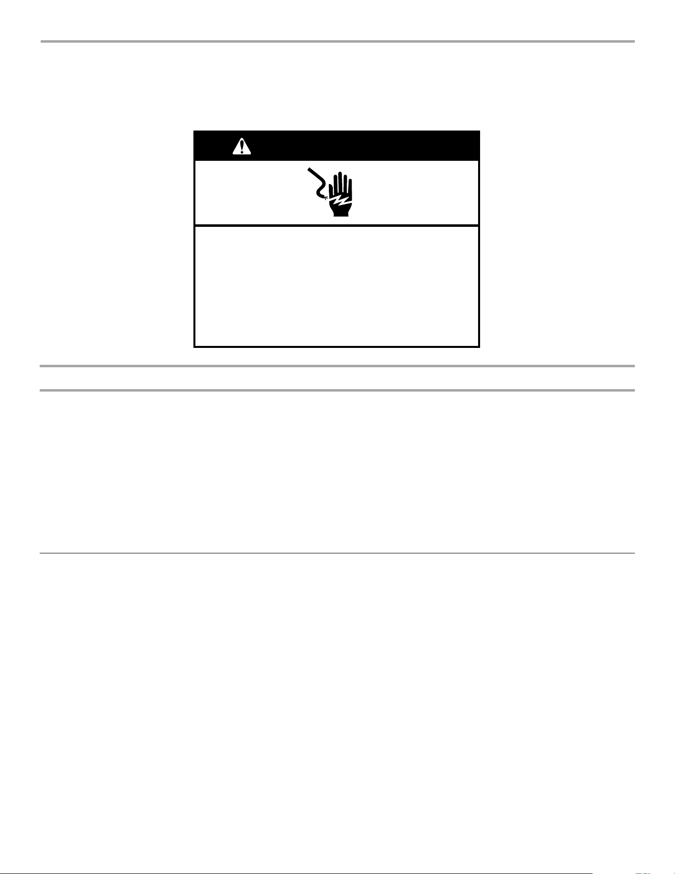
48
RÉSOLUTION DE PROBLÈMES
Essayer d’abord les solutions suggérées ici ou visiter notre site Internet et la FAQ (foire aux questions)
pour éviter le coût d'une intervention de dépannage.
Aux É.-U., www.whirlpool.com Au Canada, www.whirlpool.ca
UTILISATION GÉNÉRALE Causes possibles et/ou solutions recommandées
Le réfrigérateur
ne fonctionne pas
■ Non raccordé à une alimentation électrique - Brancher le cordon d'alimentation dans une
prise à 3 alvéoles reliée à la terre. Ne pas utiliser de cordon de rallonge.
■ Pas de courant dans la prise électrique - Brancher une lampe pour voir si la prise électrique
fonctionne.
■ Un fusible est grillé ou un disjoncteur s'est ouvert - Remplacer le fusible ou réenclencher le
disjoncteur. Si le problème persiste, contacter un électricien agréé.
■ La commande ou le refroidissement n'est pas activé(e) - Activer la commande du
réfrigérateur ou le refroidissement. Voir “Utilisation des commandes”.
■ Nouvelle installation - Attendre 24 heures après l'installation pour permettre au réfrigérateur et
au congélateur de refroidir complètement.
REMARQUE : Le fait de placer la/les commande(s) de température au réglage le plus froid ne
refroidira pas le compartiment (de réfrigération ou de congélation) plus rapidement.
Le moteur semble
fonctionner excessivement
■ Votre nouveau réfrigérateur comporte un moteur haute efficacité - Il est possible qu'il
fonctionne plus longtemps que votre appareil précédent car le compresseur et les ventilateurs
fonctionnent à des vitesses réduites plus éconergiques. Ceci est normal.
REMARQUE : L'appareil peut fonctionner encore plus longtemps si la température de la pièce
est élevée, si une grande quantité de nourriture a été ajoutée, si les portes sont fréquemment
ouvertes ou si elles ont été laissées ouvertes.
AVERTISSEMENT
Risque de choc électrique
Brancher sur une prise à 3 alvéoles reliée à la terre.
Ne pas enlever la broche de liaison à la terre.
Ne pas utiliser un adaptateur.
Ne pas utiliser un câble de rallonge.
Le non-respect de ces instructions peut causer
un décès, un incendie ou un choc électrique.

49
Le réfrigérateur
semble bruyant
Le compresseur de votre nouveau réfrigérateur régule la température plus efficacement et utilise
moins d'énergie que les modèles plus anciens. Au cours de différentes étapes du fonctionnement
de l'appareil, vous entendrez peut-être des bruits de fonctionnement normaux qui ne vous sont pas
familiers.
Les bruits suivants sont normaux :
■ Bourdonnement/Cliquetis - Se produit lorsque le robinet d'eau s'ouvre et se referme pour
distribuer de l’eau ou remplir la machine à glaçons. Si le réfrigérateur est raccordé à une
canalisation d'arrivée d'eau, cela est normal. Éteindre la machine à glaçons si le réfrigérateur
n’est pas raccordé à une canalisation d'arrivée d'eau.
■ Craquement/Écrasement - Se produit lorsque la glace est éjectée du moule à glaçons.
■ Bruit d'éclatement - Se produit lors de la contraction/l'expansion des parois internes,
particulièrement lors du refroidissement initial.
■ Pulsation/Frottement rythmique - Se produit lorsque les ventilateurs/le compresseur
s'ajustent pour optimiser la performance de l'appareil pendant son fonctionnement - cela est
normal.
■ Vibrations sonores - Se produit lorsque l'eau circule dans la canalisation d'arrivée d'eau ou
lorsque le réfrigérant circule dans l'appareil. Les vibrations peuvent aussi provenir d'objets
posés sur le réfrigérateur.
■ Bruit d'écoulement d'eau ou de gargouillement - Se produit lorsque la glace fond lors du
programme de dégivrage et que l'eau s'écoule dans le plateau de dégivrage.
■ Grésillement - Se produit à mesure que de l'eau goutte sur l'élément de chauffage durant le
programme de dégivrage.
La température
est trop élevée
■ Nouvelle installation - Attendre 24 heures après l'installation pour permettre au réfrigérateur et
au congélateur de refroidir complètement.
REMARQUE : Le fait de placer la/les commande(s) de température au réglage le plus froid ne
refroidira pas le compartiment (de réfrigération ou de congélation) plus rapidement.
■ Les portes sont ouvertes trop fréquemment ou ne sont pas complètement fermées - Ceci
permet à l'air chaud de pénétrer dans le réfrigérateur. Minimiser les ouvertures de porte, garder
les portes complètement fermées et s'assurer que l'étanchéité des deux portes est assurée.
■ Les ouvertures d'aération sont obstruées - Retirer les objets placés devant les ouvertures.
■ Une grande quantité d'aliments chauds a été récemment ajoutée - Attendre quelques
heures pour permettre au réfrigérateur de revenir à une température normale.
■ Le réglage des commandes n'est pas adapté à l'environnement de l'appareil - Ajuster les
commandes à un réglage plus froid. Contrôler à nouveau la température 24 heures plus tard.
La température
est trop basse
■ Le réglage des commandes n'est pas adapté à l'environnement de l'appareil - Ajuster les
commandes à un réglage plus chaud. Contrôler à nouveau la température 24 heures plus tard.
■ La tablette supérieure du réfrigérateur est plus froide que les tablettes inférieures - Sur
certains modèles, l’air en provenance du congélateur pénètre dans le compartiment de
réfrigération par les évents situés à proximité de la tablette supérieure. La tablette supérieure
peut donc être légèrement plus froide que les tablettes inférieures.
■ Les ouvertures d'aération sont obstruées - Retirer les objets placés devant les ouvertures.
Accumulation d'humidité
à l'intérieur de l'appareil
REMARQUE : Une certaine accumulation d'humidité est normale. Nettoyer avec un linge doux
et sec.
■ La pièce est humide - Un environnement humide contribue à l'accumulation d'humidité.
Utiliser le réfrigérateur à l'intérieur du domicile uniquement, dans un environnement aussi sec
que possible.
■ Les portes sont fréquemment ouvertes ou ne sont pas complètement fermées - Ceci
permet à l'air humide de pénétrer dans le réfrigérateur. Minimiser les ouvertures de porte,
garder les portes complètement fermées et s'assurer que l'étanchéité des deux portes est
assurée.
Les lampes intérieures
ne fonctionnent pas
■ Les portes sont restées ouvertes pendant longtemps - Fermer les portes pour réinitialiser
les lampes.
■ Une ampoule est desserrée dans la douille ou grillée - Sur les modèles possédant des
ampoules intérieures à incandescence, serrer ou remplacer les ampoules. Voir “Lampes”.
REMARQUE : Sur les modèles équipés de témoins DEL, appeler les numéros fournis pour obtenir
de l'aide ou un dépannage si les témoins lumineux intérieurs ne s'allument pas lorsqu'on ouvre une
porte. Voir la page de couverture ou la garantie pour savoir qui contacter.
UTILISATION GÉNÉRALE Causes possibles et/ou solutions recommandées
50
Les lampes du distributeur
ne fonctionnent pas
(sur certains modèles)
■ La lampe du distributeur est éteinte - Sur certains modèles, si la lampe du distributeur est
réglée à OFF (arrêt), elle ne fonctionne que si l’on appuie sur le levier/la plaque du distributeur.
Si l'on souhaite que la lampe du distributeur reste allumée continuellement, sélectionner un
autre réglage. Voir “Distributeurs d'eau et de glaçons”.
■ La lampe du distributeur est réglée au mode AUTO ou NIGHT LIGHT (veilleuse) - Sur
certains modèles, si la lampe du distributeur est réglée au mode AUTO ou NIGHT LIGHT
(veilleuse), s'assurer que le détecteur de lumière du distributeur n'est pas obstrué. Voir
“Distributeurs d'eau et de glaçons”.
REMARQUE : Sur les modèles équipés de témoins DEL, appeler les numéros fournis pour obtenir
de l'aide ou un dépannage si les témoins lumineux du distributeur ne fonctionnent pas
correctement. Voir la page de couverture ou la garantie pour savoir qui contacter.
PORTES ET NIVELLEMENT Causes possibles et/ou solutions recommandées
Les portes sont difficiles
àouvrir
■ Les joints sont sales ou collants - Nettoyer les joints et les surfaces de contact au savon
doux et à l’eau tiède. Rincer et sécher avec un linge doux.
Les portes ne ferment pas
complètement
■ La porte est bloquée en position ouverte - Déplacer les aliments sous emballage pour
dégager la porte. S'assurer que tous les balconnets et tablettes sont correctement installés.
Vérifier que tous les matériaux d'emballage ont été retirés.
Les portes semblent
mal alignées
■ L'alignement des portes ou le nivellement du réfrigérateur doit être réalisé - Voir les
instructions concernant le nivellement de l'appareil et l'alignement des portes.
Le réfrigérateur branle et
n'est pas stable
■ Le réfrigérateur n'est pas d'aplomb - Pour stabiliser le réfrigérateur, retirer la grille de la
base et abaisser les pieds de nivellement jusqu’à ce qu’ils touchent le plancher. Voir les
instructions concernant le nivellement de l'appareil et l'alignement des portes.
UTILISATION GÉNÉRALE Causes possibles et/ou solutions recommandées
AVERTISSEMENT
Risque d'explosion
Utiliser un produit de nettoyage ininflammable.
Le non-respect de cette instruction peut causer un décès,
une explosion ou un incendie.
51
GLAÇONS ET EAU Causes possibles et/ou solutions recommandées
La machine à glaçons
ne produit pas ou
produit trop peu
de glaçons, ou les
glaçons produits
sont petits/creux
■ Le réfrigérateur n'est pas raccordé à une alimentation en eau ou le robinet d'arrêt d'eau n'est
pas complètement ouvert - Raccorder le réfrigérateur à une alimentation en eau et s'assurer que le
robinet d'arrêt est complètement ouvert.
■ La canalisation d'alimentation en eau est déformée - Une déformation de la canalisation
d'alimentation en eau peut réduire le débit de l'eau, réduire la vitesse de production des glaçons,
entraîner la production de glaçons de petite taille et/ou creux, ou encore de forme irrégulière.
Redresser la canalisation d’eau.
■ La machine à glaçons n'est pas allumée - Mettre en marche la machine à glaçons. Voir “Machine à
glaçons et bac d'entreposage”.
■ Nouvelle installation - Après avoir raccordé le réfrigérateur à une source d’alimentation en eau,
vidanger le système d’eau. (Voir “Distributeurs d'eau et de glaçons”.) Attendre 24 heures pour que la
production de glaçons commence. Attendre 72 heures pour que la production de glaçons soit
complète. Jeter les trois premiers lots de glaçons produits.
■ Une grande quantité de glaçons a été récemment prélevée - Accorder suffisamment de temps à la
machine à glaçons pour produire plus de glaçons.
■ Un glaçon est coincé dans le bras éjecteur de la machine à glaçons - Retirer le glaçon du bras
éjecteur avec un ustensile en plastique.
■ Pression en eau inadéquate - Vérifier que la pression en eau du domicile est adéquate. Voir
“Spécifications de l'alimentation en eau”.
■ Le filtre à eau est mal installé - S'assurer que le filtre est correctement installé. Voir “Système de
filtration de l'eau”.
■ Un système de filtration de l'eau par osmose inverse est raccordé à votre alimentation en eau
froide - Ceci peut réduire la pression de l'eau. Voir “Spécifications de l'alimentation en eau”.
REMARQUE : Pour d'autres questions concernant la pression de l’eau, contacter un plombier agréé
qualifié.
Risque de coupure
Utiliser un verre robuste pour prendre des glaçons.
Le non-respect de cette instruction peut causer
des coupures.
AVERTISSEMENT

52
Le distributeur de
glaçons ne fonctionne
pas correctement
■ Les portes ne ferment pas complètement - S'assurer que les deux portes sont bien fermées. (Sur
certains modèles, seule la porte du congélateur doit être fermée pour pouvoir utiliser le distributeur.)
■ Nouvelle installation - Après avoir raccordé le réfrigérateur à une source d’alimentation en eau,
vidanger le système d’eau. (Voir “Distributeurs d'eau et de glaçons”.) Attendre 24 heures pour que la
production de glaçons commence. Attendre 72 heures pour que la production de glaçons soit
complète. Jeter les trois premiers lots de glaçons produits.
■ La machine à glaçons n'est pas allumée ou le bac à glaçons n'est pas bien installé - Mettre en
marche la machine à glaçons et s'assurer que le bac d'entreposage à glaçons est fermement en place.
Voir “Machine à glaçons et bac d'entreposage”.
■ Des glaçons sont agglomérés à l'intérieur du bac d'entreposage à glaçons, ou ils obstruent la
goulotte de distribution de glaçons - Retirer ou séparer les glaçons agglomérés à l'aide d'un
ustensile en plastique si nécessaire. Nettoyer la goulotte de distribution des glaçons et le fond du bac
d’entreposage à glaçons à l’aide d’un chiffon tiède et humide puis sécher soigneusement ces deux
sections. Pour éviter toute agglomération de glaçons et maintenir un approvisionnement frais en
glaçons, vider le bac d’entreposage à glaçons et nettoyer à la fois le bac d’entreposage et la goulotte
de distribution toutes les 2 semaines.
■ Les glaçons placés dans le bac d'entreposage ne conviennent pas - Utiliser uniquement des
glaçons produits par la machine à glaçons actuelle.
■ Le distributeur est verrouillé - Déverrouiller le distributeur. Voir “Distributeurs d'eau et de glaçons”.
■ Le distributeur à glaçons s'est bloqué pendant qu'il distribuait de la glace concassée - Pour les
modèles comprenant un bac d'entreposage à glaçons dans la porte, pour éliminer l'obstruction,
passer temporairement de la glace concassée au mode glaçons.
■ On a appuyé sur la plaque/le levier du distributeur pendant trop longtemps - Les glaçons cessent
automatiquement d'être distribués. Attendre quelques minutes pour que le distributeur soit réinitialisé
et reprenne ensuite la distribution. Prendre de grandes quantités de glaçons directement du bac
d'entreposage à glaçons et non depuis le distributeur.
■ La pression en eau du domicile est inférieure à 30 lb/po² (207 kPa) - La pression de l'eau du
domicile affecte le débit au niveau du distributeur. Voir “Spécifications de l'alimentation en eau”.
■ Le filtre à eau est obstrué ou mal installé - Remplacer le filtre ou le réinstaller correctement. Voir
“Système de filtration de l'eau”.
Mauvais goût, odeur
ou couleur grisâtre
des glaçons
ou de l’eau
■ Raccords de plomberie neufs - Des raccords de plomberie neufs peuvent entraîner une décoloration
ou un mauvais goût des glaçons ou de l’eau. Ce problème devrait disparaître avec le temps.
■ Les glaçons ont été entreposés pendant trop longtemps - Jeter les glaçons et laver le bac à
glaçons. Accorder 24 heures à la machine à glaçons pour la fabrication de nouveaux glaçons.
■ L'odeur de certains aliments s'est transférée à l'eau ou aux glaçons - Utiliser des emballages
hermétiques et à l'épreuve de l'humidité pour conserver les aliments.
■ Utilisation d'une canalisation d'alimentation en eau non recommandée - L'odeur et le goût de
certains matériaux utilisés dans des canalisations d'alimentation en eau non recommandées peuvent
se transférer à l'eau. Utiliser uniquement une canalisation d'alimentation en eau recommandée. Voir
“Spécifications de l'alimentation en eau”.
■ L'eau contient des minéraux (tels le soufre) - L'installation d'un filtre à eau peut être requise afin
d'enlever ces minéraux.
■ Le filtre à eau a été récemment installé ou remplacé - Une décoloration grise ou foncée de la glace
ou de l’eau indique que le système de filtration de l’eau nécessite un rinçage supplémentaire. Voir
“Distributeurs d'eau et de glaçons”.
GLAÇONS ET EAU Causes possibles et/ou solutions recommandées

53
ACCESSOIRES
Les accessoires de réfrigérateur suivants sont disponibles. Pour
commander, composer le 1-800-442-9991 et demander le
numéro de pièce indiqué ci-dessous ou contacter votre marchand
autorisé Whirlpool. Au Canada, composer le 1-800-807-6777.
Nettoyant pour acier inoxydable affresh
®
:
Commander la pièce numéro W10355016
Au Canada, commander la pièce numéro W10355016B
Lingettes pour acier inoxydable affresh
®
:
Commander la pièce numéro W10355049
Au Canada, commander la pièce numéro W10355049B
Nettoyant pour appareil ménager et cuisine affresh
®
:
Commander la pièce numéro W10355010
Au Canada, commander la pièce numéro W10355010B
Filtre à eau :
Commander la pièce N° W10295370A (P4RFWB)
Filtre à air :
Commander la pièce N° W10311524
Sachet de conservation pour produits frais :
Commander la pièce N° W10346771
Le distributeur d’eau
ne fonctionne pas
correctement
■ Les portes ne ferment pas complètement - S'assurer que les deux portes sont bien fermées. (Sur
certains modèles, seule la porte du congélateur doit être fermée pour pouvoir utiliser le distributeur.)
■ Le réfrigérateur n'est pas raccordé à une alimentation en eau ou le robinet d'arrêt d'eau n'est
pas ouvert - Raccorder le réfrigérateur à une alimentation en eau et s'assurer que le robinet d'arrêt est
complètement ouvert.
■ La canalisation d'alimentation en eau est déformée - Une déformation de la canalisation
d'alimentation en eau peut réduire le débit du distributeur. Redresser la canalisation d’eau.
■ La pression en eau du domicile est inférieure à 30 lb/po² (207 kPa) - La pression de l'eau du
domicile affecte le débit au niveau du distributeur. Voir “Spécifications de l'alimentation en eau”.
■ Nouvelle installation - Après avoir raccordé le réfrigérateur à une source d’alimentation en eau,
vidanger le système d’eau. Voir “Distributeurs d'eau et de glaçons”.
■ Le distributeur est verrouillé - Déverrouiller le distributeur. Voir “Distributeurs d'eau et de glaçons”.
■ Le filtre à eau est obstrué ou mal installé - Remplacer le filtre ou le réinstaller correctement. Voir
“Système de filtration de l'eau”.
■ Un système de filtration de l'eau par osmose inverse est raccordé à votre alimentation en eau
froide - Ceci peut réduire la pression de l'eau. Voir “Spécifications de l'alimentation en eau”.
REMARQUE : Pour d'autres questions concernant la pression de l’eau, contacter un plombier agréé
qualifié.
De l'eau suinte
ou goutte du
distributeur
REMARQUE : Il est normal que quelques gouttes s'écoulent de la machine après que l'on a distribué
de l'eau.
■ On n'a pas gardé le verre sous le distributeur pendant suffisamment longtemps - Maintenir le
verre sous le distributeur pendant 2 à 3 secondes après avoir relâché le levier/la plaque du distributeur.
■ L'installation est neuve, le filtre à eau a été récemment installé ou changé - De l’air piégé dans les
canalisations peut faire goutter le distributeur d'eau. Rincer le système de distribution d'eau pour
évacuer l'air des canalisations. Voir “Distributeurs d'eau et de glaçons”.
■ De la glace restée dans la goulotte du distributeur fond - S'assurer qu'il n'y a aucun copeau ou
morceau de glace dans la goulotte à glaçons.
De l'eau fuit par
l'arrière du
réfrigérateur
■ Les raccords des canalisations d'eau ne sont pas bien serrés - S'assurer que tous les raccords
sont bien serrés. Voir “Raccordement de la canalisation d'eau”.
L'eau du distributeur
n'est pas assez froide
(sur certains modèles)
REMARQUE : L'eau du distributeur est refroidie à 50°F (10°C).
■ Nouvelle installation - Attendre 24 heures après l'installation pour que l'alimentation en eau
refroidisse complètement.
■ Une grande quantité d'eau a été récemment versée - Attendre 24 heures pour qu'une nouvelle
réserve d'eau refroidisse complètement.
■ On n'a pas versé d'eau récemment - Le premier verre d'eau ne sera peut-être pas froid. Jeter le
premier verre d’eau distribué.
■ Le réfrigérateur n'est pas raccordé à une canalisation d'arrivée d'eau froide - S'assurer que le
réfrigérateur est raccordé à une canalisation d'arrivée d'eau froide. Voir “Spécifications de
l'alimentation en eau”.
GLAÇONS ET EAU Causes possibles et/ou solutions recommandées
54
FEUILLE DE DONNÉES SUR LA PERFORMANCE
Système de filtration d’eau
Modèle P5WB2L/P4RFWB Capacité 200 gallons (757 litres)
Ce produit a été testé selon les normes NSF/ANSI 42 et 53 pour la réduction des substances énumérées ci-dessous. La concentration des
substances indiquées dans l'eau entrant dans le système a été réduite à une concentration moindre ou égale à la limite permissible pour
l'eau qui quitte le système, tel que spécifié dans les normes NSF/ANSI 42 et 53.
Paramètres de test : pH = 7,5 ± 0,5 à moins d'indications contraires. Débit = 0,5 gpm (1,9 Lpm). Pression = 60 lb/po² (413,7 kPa).
Temp. = 68°F à 71,6°F (20°C à 22°C). Capacité de service nominale = 200 gallons (757 litres).
■ Il est important que les critères de fonctionnement, d'entretien
et de remplacement du filtre soient respectés pour que le
produit donne le rendement annoncé. Des dommages
matériels peuvent subvenir si toutes les instructions ne sont
pas respectées.
■ Utiliser la cartouche de remplacement P4RFWB, pièce
n° W10295370A. Prix au détail suggéré en 2013 de
39,99 $US/49,99 $CAN. Les prix sont sujets à modification
sans préavis.
Style 1 – Lorsque l’écran d’affichage de l’état du filtre à eau
passe de “GOOD” (bon) à “ORDER” (commander),
commander un nouveau filtre. Lorsque le témoin indique
“REPLACE” (remplacer), il est recommandé de remplacer le
filtre.
Style 2 – Lorsque le témoin du filtre passe du vert au jaune,
commander un nouveau filtre. Lorsque le témoin passe du
jaune au rouge, il est recommandé de remplacer le filtre.
Style 3 – Lorsque le témoin du filtre indique 10 %,
commander un nouveau filtre. Lorsque le témoin indique 0 %,
il est recommandé de remplacer le filtre.
Style 4 – Appuyer sur FILTER (filtre) pour vérifier l'état du filtre
à eau. Lorsque le témoin lumineux du filtre est jaune,
commander un nouveau filtre. Si le témoin lumineux du filtre
est rouge, il est recommandé de remplacer le filtre.
■ Après avoir changé le filtre à eau, vidanger le système de
distribution d'eau. Voir “Distributeurs d'eau et de glaçons” ou
“Distributeur d'eau” dans les instructions d’utilisation ou le
guide d’utilisation.
■ Ces contaminants ne sont pas nécessairement présents dans
votre approvisionnement d'eau. Même si le test a été effectué
dans des conditions de laboratoires standard, le rendement
réel peut varier.
■ Le produit doit être utilisé pour l'eau froide seulement.
■ Le circuit d’eau doit être installé conformément aux lois et
règlements locaux et à ceux de l’État concerné.
■ Ne pas utiliser pour le filtrage d'une eau microbiologiquement
polluée ou de qualité inconnue en l'absence d'un dispositif de
désinfection adéquat avant ou après le système. Les
systèmes certifiés pour la réduction de kyste peuvent être
utilisés pour l'eau désinfectée qui peut contenir des kystes
filtrables.
■ Consulter la section “Garantie” (dans les instructions
d’utilisation ou le guide d’utilisation) pour obtenir le nom,
l'adresse et le numéro de téléphone du fabricant.
■ Consulter la section “Garantie” (dans les instructions
d’utilisation ou le guide d’utilisation) pour voir la garantie
limitée du fabricant.
Directives d'application/
Paramètres d'approvisionnement en eau
Produit testé et certifié par NSF International en vertu de la norme
NSF/ANSI 42 (réduction du goût et de l'odeur du chlore, et particules
de classe I*) et en vertu de la norme NSF/ANSI 53 (réduction de kystes
actifs, amiante, plomb, lindane, toxaphène, atrazine, et 2,4 - D).
Réd. de substances
Effets esthétiques
Critères de
réduction NSF
Affluent
moyen
Concentration dans l'eau
àtraiter
Effluent maximal % de réd.
minimale
% de réd.
moyenne
Chlore goût/odeur
Particules (classe I*)
réduction de 50 %
réduction de 85 %
2,0 mg/L
7 300 000 #/mL
2,0 mg/L ± 10 %
Au moins 10 000 particules/mL
0,20 mg/L
75 000 #/mL
**
97
99
97,2
99,4
Réduction des
contaminants
Critères de
réduction NSF
Affluent
moyen
Concentration dans l'eau
àtraiter
Effluent maximal % de réd.
minimale
% de réd.
moyenne
Kystes actifs
†
99,95 % 160 000/L 50 000/L min. 54/L
†
99,97 99,99
Amiante 99 % 87 MFL 10
7
à 10
8
fibres/L
††
0,17 MFL 99 99
Plomb : à pH 6,5
Plomb : à pH 8,5
0,010 mg/L
0,010 mg/L
0,160 mg/L
0,140 mg/L
0,15 mg/L ± 10 %
0,15 mg/L ± 10 %
0,001 mg/L
0,005 mg/L
99,4
98,6
99,4
98,6
Lindane 0,0002 mg/L 0,0019 mg/L 0,002 mg/L ± 10 % 0,00002 mg/L 98,9 99
Toxaphène 0,003 mg/L 0,014 mg/L 0,015 mg/L ± 10 % 0,001 mg/L 93 93
Atrazine 0,003 mg/L 0,0094 mg/L 0,009 mg/L ± 10 % 0,0005 mg/L 94,5 94,7
2,4 - D 0,07 mg/L 0,220 mg/L 0,210 mg/L ± 10 % 0,028 mg/L 87,5 96,1
Source d'eau
Pression de l'eau
Température de l'eau
Débit nominal
Collectivité ou puits
30 - 120 lb/po² (207 - 827 kPa)
33° - 100°F (0,6° - 37,8°C)
0,5 gpm (1,9 L/min) à 60 lb/po²
*
**
†
††
Classe I - taille des particules : > 0,5 à <1 um
Exigence de test : au moins 100 000 particules/mL (poussière de test fine AC).
Cas de la filtration de kystes de Cryptosporidium parvum
Fibres de longueur supérieure à 10 um
® NSF est une marque déposée de NSF International.
55
GARANTIE DE GROS APPAREIL MÉNAGER
WHIRLPOOL CORPORATION
GARANTIE LIMITÉE
Pendant un an à compter de la date d’achat, lorsque ce gros appareil ménager est utilisé et entretenu conformément aux instructions
jointes à ou fournies avec le produit, Whirlpool Corporation ou Whirlpool Canada LP (ci-après désignées “Whirlpool”) paiera pour les
pièces spécifiées par l’usine et la main-d’œuvre pour corriger les vices de matériaux ou de fabrication qui existaient déjà lorsque ce
gros appareil ménager a été acheté. Le service doit être fourni par une compagnie de service désignée par Whirlpool. LE SEUL ET
EXCLUSIF RECOURS DU CLIENT DANS LE CADRE DE LA PRÉSENTE GARANTIE LIMITÉE CONSISTE EN LA RÉPARATION PRÉVUE
CI-DESSUS. Cette garantie limitée est valide uniquement aux États-Unis ou au Canada et s’applique exclusivement lorsque le gros
appareil ménager est utilisé dans le pays où il a été acheté. Une preuve de la date d’achat d’origine est exigée pour obtenir un service
dans le cadre de la présente garantie limitée.
ÉLÉMENTS EXCLUS DE LA GARANTIE
La présente garantie limitée ne couvre pas :
1. Les pièces de rechange ou la main-d’œuvre lorsque ce gros appareil ménager est utilisé à des fins autres que l'usage domestique
unifamilial normal ou lorsque les instructions d’installation et/ou les instructions de l’opérateur ou de l’utilisateur fournies ne sont
pas respectées.
2. Les visites de service pour rectifier l'installation du gros appareil ménager, montrer à l'utilisateur comment utiliser le gros appareil
ménager, remplacer ou réparer des fusibles du domicile ou rectifier le câblage ou la plomberie du domicile.
3. Les visites de service pour réparer ou remplacer les ampoules électriques, les filtres à air ou les filtres à eau de l'appareil. Les pièces
consomptibles ne sont pas couvertes par la garantie.
4. Les dommages imputables à : accident, modification, usage impropre ou abusif, incendie, inondation, actes de Dieu, installation
fautive ou installation non conforme aux codes d’électricité ou de plomberie, ou l’utilisation de produits non approuvés par
Whirlpool.
5. Les défauts d'apparence, notamment les éraflures, traces de choc, fissures ou tout autre dommage subi par le fini du gros appareil
ménager, à moins que ces dommages ne résultent de vices de matériaux ou de fabrication et ne soient signalés à Whirlpool dans
les 30 jours suivant la date d'achat.
6. Toute perte d'aliments ou de médicaments due à une défaillance du réfrigérateur ou du congélateur.
7. Le ramassage et la livraison. Ce gros appareil ménager est conçu pour être réparé à domicile.
8. Les réparations aux pièces ou systèmes résultant d’une modification non autorisée faite à l’appareil.
9. Les frais de déplacement et de transport pour le service du produit si votre gros appareil ménager est situé dans une région
éloignée où un fournisseur de services d’entretien ou de réparation Whirlpool autorisé n’est pas disponible.
10. La dépose et la réinstallation de votre gros appareil ménager si celui-ci est installé dans un endroit inaccessible ou n'est pas installé
conformément aux instructions d'installation fournies par Whirlpool.
11. Les pièces de rechange ou la main-d’œuvre pour les gros appareils ménagers dont les numéros de modèle/de série ont été
enlevés, modifiés ou ne peuvent pas être facilement identifiés.
12. La décoloration ou l'oxydation des surfaces en acier inoxydable ou encore l'apparition de rouille sur ces surfaces.
Le coût d’une réparation ou d'un remplacement dans le cadre de ces circonstances exclues est à la charge du client.
CLAUSE D'EXONÉRATION DE RESPONSABILITÉ AU TITRE DES GARANTIES IMPLICITES
LES GARANTIES IMPLICITES, Y COMPRIS LES GARANTIES APPLICABLES DE QUALITÉ MARCHANDE OU D'APTITUDE À UN
USAGE PARTICULIER, SONT LIMITÉES À UN AN OU À LA PLUS COURTE PÉRIODE AUTORISÉE PAR LA LOI. Certains États et
provinces ne permettent pas de limitation sur la durée d’une garantie implicite de qualité marchande ou d'aptitude à un usage
particulier, de sorte que la limitation ci-dessus peut ne pas être applicable dans votre cas. Cette garantie vous confère des droits
juridiques spécifiques, et vous pouvez également jouir d’autres droits qui peuvent varier d’une juridiction à l'autre.
LIMITATION DES RECOURS; EXCLUSION DES DOMMAGES FORTUITS OU INDIRECTS
LE SEUL ET EXCLUSIF RECOURS DU CLIENT DANS LE CADRE DE LA PRÉSENTE GARANTIE LIMITÉE CONSISTE EN LA
RÉPARATION PRÉVUE CI-DESSUS. WHIRLPOOL N’ASSUME AUCUNE RESPONSABILITÉ POUR LES DOMMAGES FORTUITS OU
INDIRECTS. Certains États et certaines provinces ne permettent pas l’exclusion ou la limitation des dommages fortuits ou indirects, de
sorte que ces limitations et exclusions peuvent ne pas être applicables dans votre cas. Cette garantie vous confère des droits juridiques
spécifiques, et vous pouvez également jouir d’autres droits qui peuvent varier d’une juridiction à l'autre.
Si vous résidez à l'extérieur des 50 États des États-Unis et du Canada, contactez votre marchand Whirlpool autorisé pour déterminer si
une autre garantie s'applique. 7/12

Pour des informations supplémentaires sur le produit, aux É.-U., visiter www.whirlpool.com.
Au Canada, visiter www.whirlpool.ca.
Si vous n’avez pas accès à Internet et que vous nécessitez une assistance pendant l’utilisation du produit ou que vous souhaitez
prendre un rendez-vous, vous pouvez contacter Whirlpool au numéro ci-dessous.
Ayez votre numéro de modèle à disposition. Vous pouvez trouver vos numéros de modèle et de série sur la plaque située sur la paroi
interne du compartiment de réfrigération.
Pour assistance ou service aux É.-U., composez le 1-800-253-1301. Au Canada, composez le 1-800-807-6777.
Si vous avez besoin de plus d’assistance, vous pouvez écrire à Whirlpool en soumettant toute question ou problème à l’adresse
suivante :
Aux États-Unis :
Whirlpool Brand Home Appliances
Customer eXperience Center
553 Benson Road
Benton Harbor, MI 49022-2692
Au Canada :
Whirlpool Brand Home Appliances
Centre d'eXpérience à la clientèle
200 – 6750 Century Ave.
Mississauga, Ontario L5N 0B7
Dans votre correspondance, veuillez indiquer un numéro de téléphone où l’on peut vous joindre dans la journée.
Veuillez conserver toutes les instructions fournies ainsi que le numéro de modèle pour référence ultérieure.
W10571759A
EN/FR PN W10561345A
®
/™ ©2013 Whirlpool. Used under license in Canada. All rights reserved.
Usada en Canadá bajo licencia. Todos los derechos reservados.
Utilisé sous licence au Canada. Tous droits réservés.
2/13
Printed in Mexico
Impreso en México
Imprimé au Mexique