Loading ...
Loading ...
Loading ...
Assemble right hand lift pivot plate,(stamped
P,H.), over right hand end of lift assembly pivot
shaft and connect to outside of frame (see figure
14) using two 3/8" x 3/4" clevis pins from
inside- Secure with two 3/32" (small) hairpin
cotters and two 1/8"(large) hairpin cotters
assembled to each end of pivot shaft. See figure
14.
,,,i
318" X 314" CLEVIS PINS
LIFT ASS'Y. PIVOT SHAFT MOUNT PLATE (R.H.)
_" FRONT___
RIGHT HAND SIDE VIEW
FIGURE 14
15,
16.
Move tractor lift control lever forward (see figure
18, page 8) to lower link rods outside of short
arms on lift assembly. See figure _5.
Assemble one t/2" x t" clevis pin from inside
through short arm through right hand link rod,
and through one t7/32" x 1-1/2" washer. Secure
with one 1/8" (large) hairpin cotter on outside.
See figure 15o
Assemble one 1f2" x 1" clevis pin from outside
(on left side of tractor), through one 17/32" x
1-112" washer, through left hand link rod, and
through short arm. Secure with one 1/8" hair-
pin cotter on inside.
17_ Assemble guide bracket assembly shaft end
into the teft hand hitch plate See figure 16. Slide
guide assembly back to the right and into hole
of the right hand hitch plate. Secure with a 1/8"
(large) hairpin cotter ih each end, See figure 17.
Lower front end of guide bracket assembly to
straddle channel assembly,
FRONT
PIVOT SHAFT L
HITCH
PLATE (R.H.),'.,
GUIDE BRACKET ASS'Y.
HITCH
PLATE, {LHo}
FIGURE 16
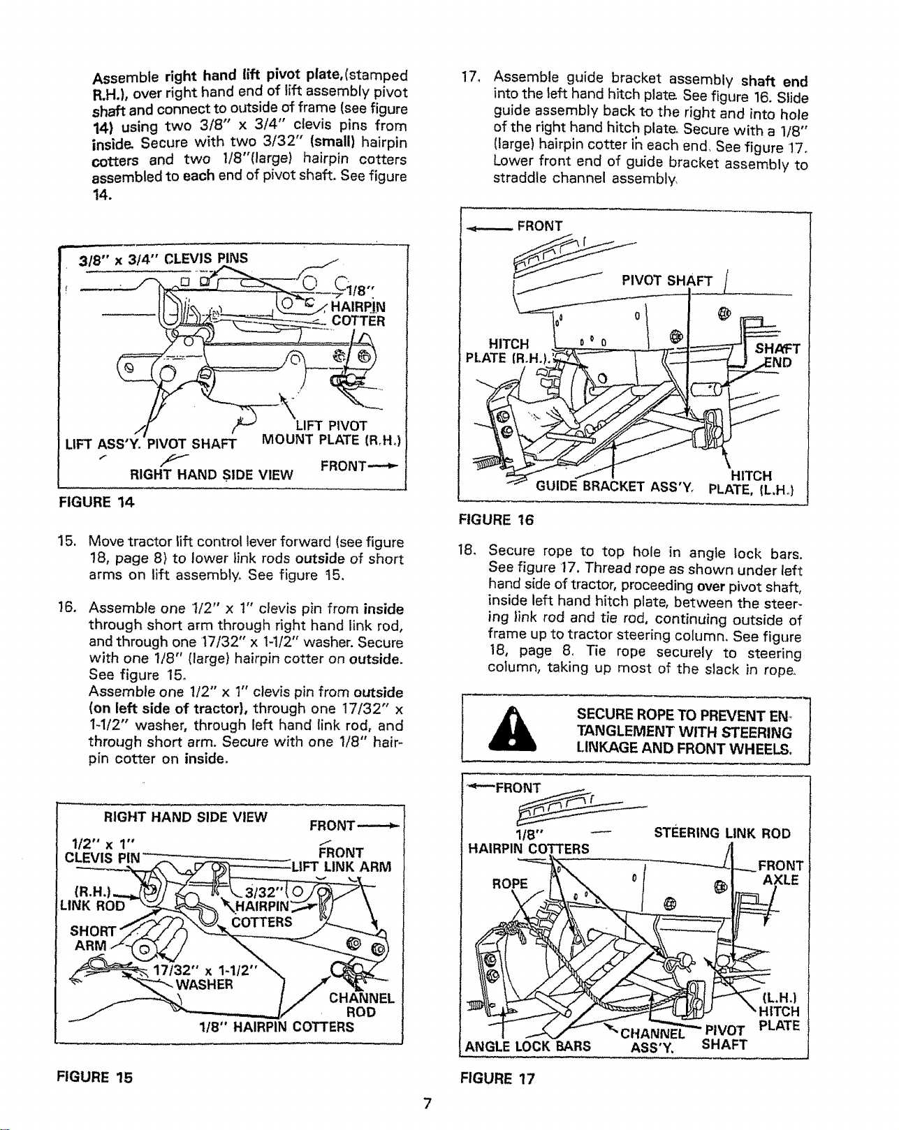
18. Secure rope to top hole in angle lock bars.
See figure 17. Thread rope as shown under left
hand side of tractor, proceeding over pivot shaft,
inside left hand hitch plate, between the steer-
ing link rod and tie rod, continuing outside of
frame up to tractor steering column, See figure
18, page 8. Tie rope securely to steering
cotumn, taking up most of the slack in rope.
SECURE ROPE TO PREVENT EN_
TANGLEMENT WITH STEERING
LINKAGE AND FRONT WHEELS.
t RIGHT HAND SIDE VIEW FRONT,--.--_]
112"x1" --__ ONT l
CLEVI_S PiN" ..-.. __ -"LIFT LINK ARM 1
SHORTf/ /!i3 /
I __ ......... J I CHANNEL I
[-J :oo W °j
FIGURE 15
7
1/8" _ STEERING LINK ROD
HAIRPIN COTTERS
_ -J ..._ FRONT
ot AXLE
(L,H.)
/__ HITCH
_i,_CHANNE_ PIVOT PLATE
FIGURE 17
Loading ...
Loading ...
Loading ...