+
ROOMAI CONDITIONE
E WS
Please read the operating instructions and safety precautions
carefully and thoroughly before installing and operating your
room air conditioner.
MANUEL
1" U EF
Veuiltez lire attentivement et en entier ce guide d'utifisation
et les mesures de securite ci-incluses avant de preceder &
Hnstallation et au fonctionnement de votre climatiseur.
D'UTiLISATION
A
ET
AIRE ACONDICIONADO
E
Pot favor lea las instrucciones de operaciOn y tas precauciones
de seguridad cuidadosa y totalmente antes de instalar y operar
su acondicionador de aire de ventana.
MODELS, MODELES, MODELO: HBLG18H
Manufactured by LG Electronics
+
FOR YOUR R£CORDS
Stapleyour receiptto t,_ispage in easeyou needit later.
Writedown the modeland serialnumbershere:
Model#
Serial#
Youcan find themon a labelon the side of eachuniL
Dealer'sName
DatePurchased
READ THIS MANUAL
inside you will find many helpful hints on how to use and
maintainyour air conditionerproperly.Just a little preventive
care on your part can save you a great deal of time and
moneyover the life of your airconditioner.
You'll find many answers to common problems in the chart
of troubleshooting tips If you review our chart of
Troubleshooting Tips first, you may not need to ca[[ for
service at all
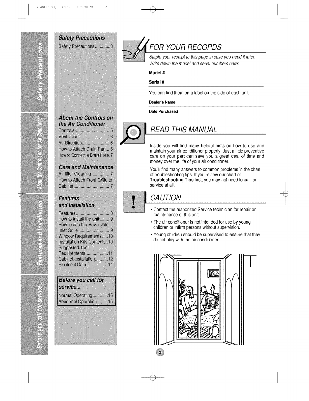
CAUTION
* Contact the authorized Service technician for repair or
maintenance of this unit.
• The airconditioneris not intend_ for use by young
childrenor infirm personswithoutsupervision.
• Youngchildrenshould besupervisedto ensurethat they
do not playwith the airconditioner.
÷
+
fety Pre utions
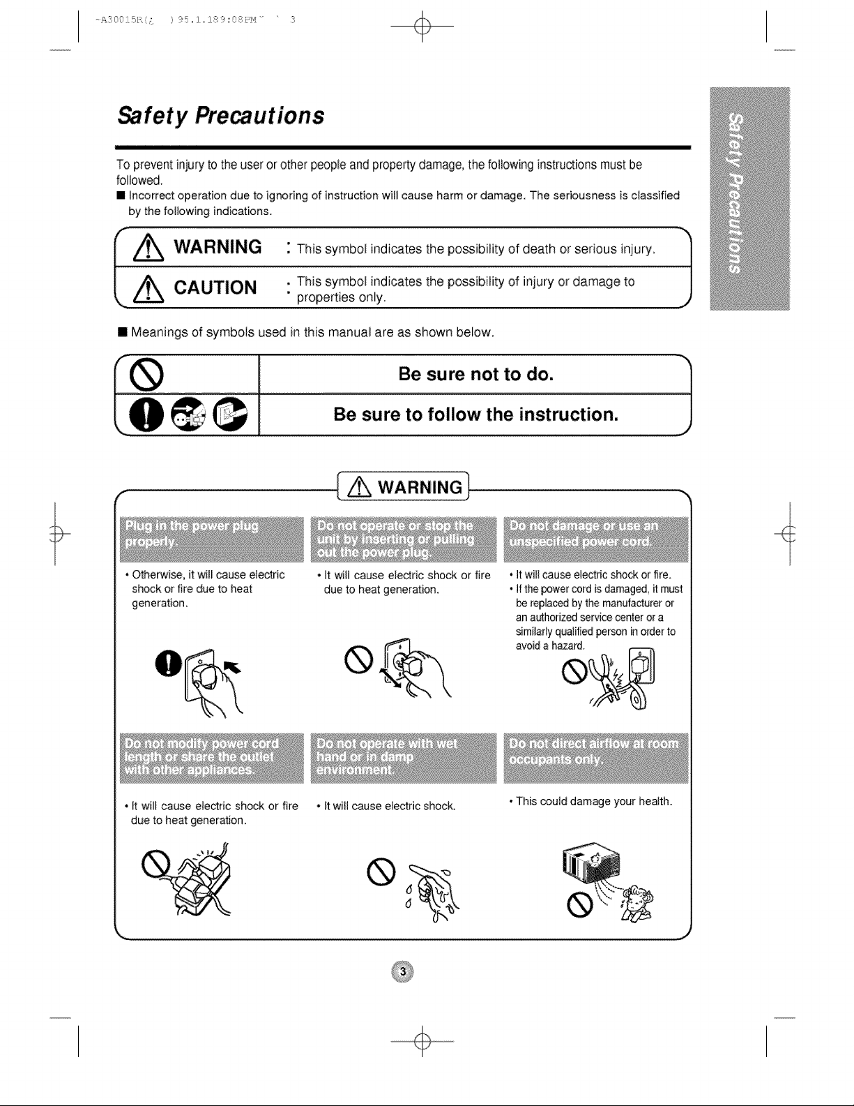
To preventinjury to the useror other peopleand propertydamage,the followinginstructionsmustbe
followed,
• Incorr_t operation due to ignoring of instruction will cause harm or damage The seriousness is classified
by the following indications.
L,±
" This symbol indicates the possibility of death or serious injury.
, This symbol indicates the possibility of injury or damage to /
" properties only.
J
II Meanings of symbols used inthis manual are as shown below.
L €_ Be sure to follow the instruction. J
. Otherwise, it will cause electric
shock or fire due to heat
generation,
• It will cause eledric shock or fire
due to heat generation.
_ WARNING
• It will cause electric shock or fire
due to heat generation.
• l;twill cause electric shock,
• It will cause electric shod_ or fire,
• If the power cord is damaged, _ must
be replaced by the manutacturer or
an authorized service center or a
similarly qualified person in order to
avoid a hazard.
• This could damage your health.
÷
A3001£,/;, ;: ) 95,:]_284_:(s:P_'_ .... 4
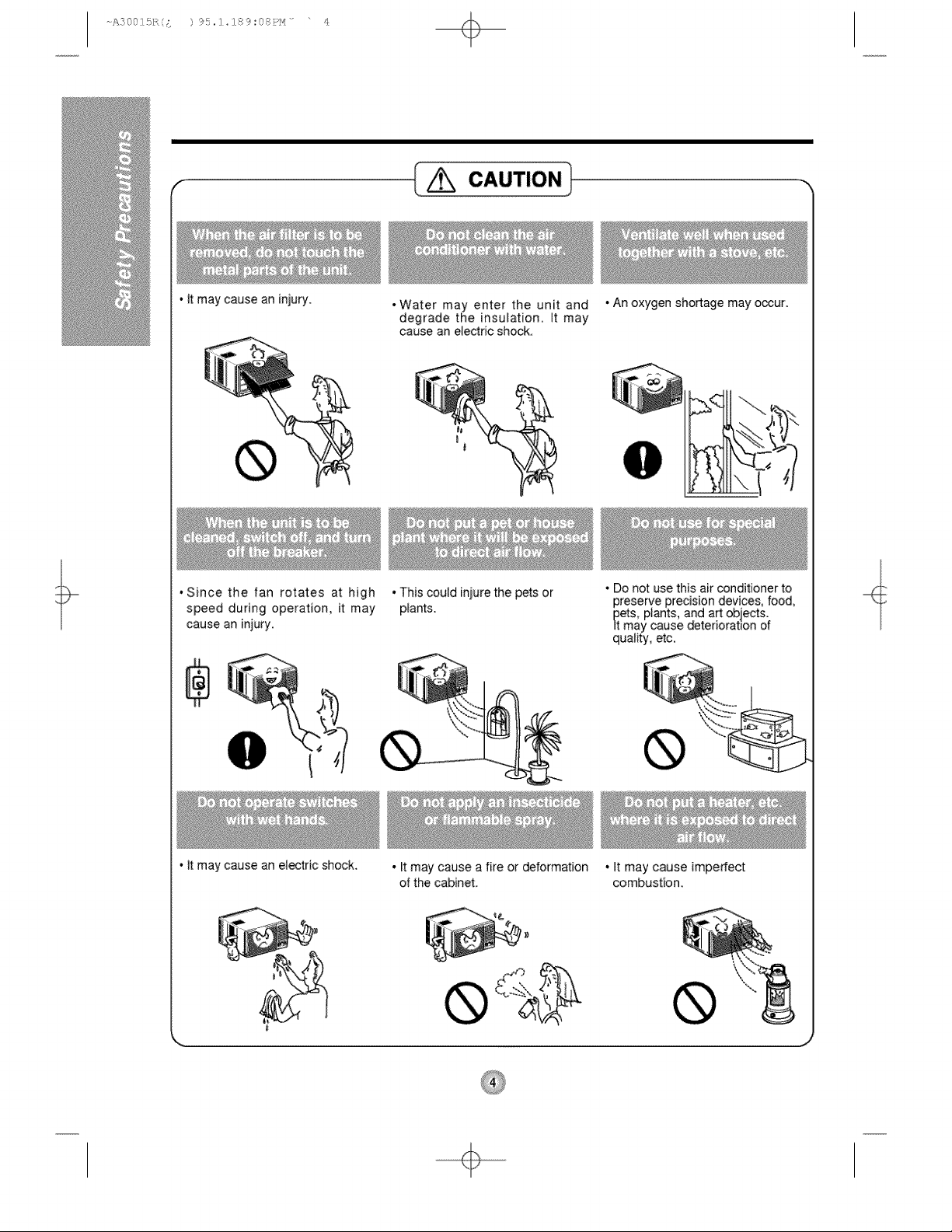
• It may cause an injury.
r
CAUTION)
,Since the fan rotates at high
speed during operation, it may
cause an injury.
• It may cause an electric shock.
• Water may enter the unit and
degrade the insulation, tt may
cause an electric shock.
, This could iniure the pets or
plants.
• It may cause a fire or deformation
of the cabinet.
• An oxygen shortage may oocur.
• Do not use this air conditioner to
preserve precision devices, food,
pets, plants, and art objects.
It may cause _terioratlon of
quatity etc,
®
• It may cause imperfect
combustion.
,i
÷
About the ntrols on the Air nditioner
The controls will look like one of the following.
• WARNING
To reduce the risk of fire, electric shock, or injury to persons, read the IMPORTANT
SAFETY INSTRUCTIONS before operating this appliance.
• CAUTION
When the air conditioner has been performing its cooling operation and is turned off
or set to the fan position, wait at least 3 minutes before resetting to the cooling
operation again.
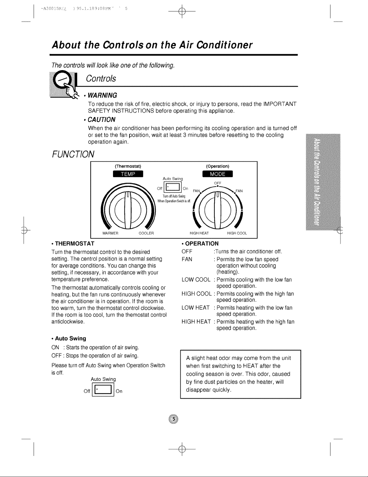
(Thermostat) (Operation)
llli]ji-ir_
WARMER COOLER HiGH H_T H_GH COOL
• THERMOSTAT
Turn the thermostat control to the desired
setting. The centrot position is a normal setting
for average conditions. You can change this
setting, if necessary, in accordance with your
temperature preference,
The thermostat automatically controls cooting or
heating, but the fan runs continuously whenever
the air conditioner is in operation, tf the room is
too warm, turn the thermostat controi clockwise,
if the room is too cool, turn the themostat control
anticlockwise.
• Auto Swing
ON : Startsthe operationof air swing.
OFF : Stopsthe operationof air swing.
Pleaseturn off Auto Swingwhen OperationSwitch
is off.
Auto Swing
Off On
• OPERATION
OFF :Turns the air conditioner off
FAN
LOW COOL
HIGH COOL
LOW HEAT
HIGH HEAT
Permits the low fan speed
operation without cooling
(heating).
Permits cooling with the low fan
speed operation.
Permits cooling with the high fan
speed operation.
Permits heating with the low fan
speed operation.
Permits heating with the high fan
speed operation.
A slight heat odor may come from the unit
when first switching to HEAT after the
cooling season is over. This odor, caused
by fine dust particles on the heater, will
disappear quickly.
÷
A2001£,/;, { ) 95,;]_284_:(s:Pt_ ....
+
Additional controls and important information.
Ventilation
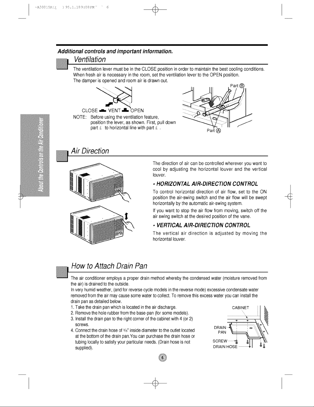
The ventilationlever mustbe in the CLOSEpositioninorderto maintainthe bestcooling conditions.
When freshair is necessaryin the room,set the ventilationleverto theOPEN position.
The damperis openedand room airis drawnout.
, , Part (_1
NOTE: Before usingthe ventilationfeature, "_
_sition the lever,as shown. First,pull _wn
part £ to horizontal line with part £. Part
Air Direction
The directionof air can be controlledwhereveryou wantto
cool by adjusting the horizontal louver and the vertical
buyer.
• HORIZONTAL AIR-DIRECTION CONTROL
To control horizontal direction of air flow, set to the ON
position the air-swingswitch and the air flow will be swept
horizontallyby the automaticair-swingsystem
If you wantto stop the air flow from moving,switch off the
airswingswitchat the desired positionof the vane
• VERTICAL AIR.DIRECTION CONTROL
The vertical air direction is adjusted by moving the
horizontallouver.
How to Attach Drain Pan
Theair conditioneremploysa properdrainmethodwherebythe condensedwater(moistureremovedfrom
the air)isdranedto theoutside.
Inveryhumidweather,(andfor reversecyclemodelsinthereversemode)excessivecondensatewater
removedfromthe airmaycausesomewatertocoiled. To removethisexcesswateryoucaninstallthe
drainpanas detailedbelow.
1 Takethe drainpanwhichis located:inthe airdischarge. ,k
2. Removethe holerubberfromthe base-pan(forsomemodels).
3 Installthe drainpanto therightcornerof thecabinetwith 4 (or2}
screws.
4 Connectthedrain hoseof sis"insidediameterto theoutletlocated \,
atthe bosomof thedrainpan.Youcanpurchasethe drainhoseor
tubinglocallyto satisfyyourparticularneeds.(Drainhoseis not
supplied).
÷
A200SL,/;, { ) 95,:]_284_:(s:Pt_ ....
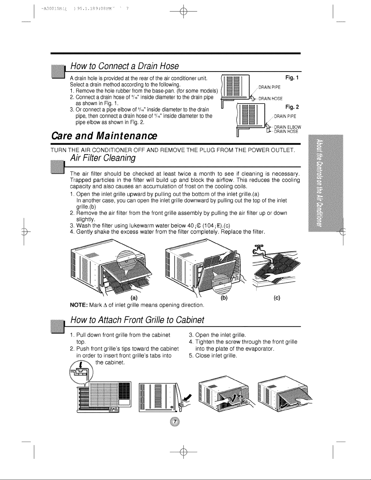
How to Connect a Drain Hose
A drainholeis providedat the rearof the air conditionerunit,
Selecta drain methodaccordingto the following.
1 Removethe hole rubberfrom the base@an,(for some models)
2. Connecta drain hoseof %°"insidediameterto the drain pipe
as shownin Fig. t.
3. Orconnecta pipe elbowof 9/,/,inside diameterto thedrain
pipe,then connecta drainhose of %/inside diameterto the
pipeelbowas ShOwnin Fig. 2.
_ L ,DRAIN RiPE
DRAIN HOSE
Fig. 1
Care and Maintenan_
TURN THE AIR CONDITIONER OFF AND REMOVE THE PLUG FROM THE POWER OUTLET.
Air Filter Cleaning
The air filter should be checked at least twice a month to see if cteaning is necessary
Trapped particles in the filter will build up and block the airflow. This reduces the cooling
capacity and also causes an accumulation of frost on the cooling coils.
1. Open the inlet gritle upward by pulling out the bottom of the inlet grille.(a)
In another case, you can open the inlet grille downward by pulling out the top of the inlet
grille.(b)
2. Remove the air filter from the front grille assembly by pulling the air filter up or down
slightly.
3. Wash the filter using lukewarm water below 40 ;6 (104 iF).(c)
4, Gently shake the excess water from the filter completely, Replace the filter,
(a)
NOTE: Mark A of inletgrille means opening direction.
(b) (c)
How to Attach Front Grille to Cabinet
1. Pull down front grille from the cabinet
top.
2. Push front gritle's tips toward the cabinet
in order to insert front grille's tabs into
the _binet.
]ololI ,
3. Open the inlet grille.
4. Tighten the screw through the front grille
into the plate of the evaporator.
5. Close inlet grille.
÷
A:}00]£,/;, ;. ) 95,:]_28<_:(s:P_'_ .... 8
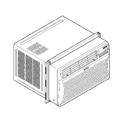
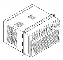
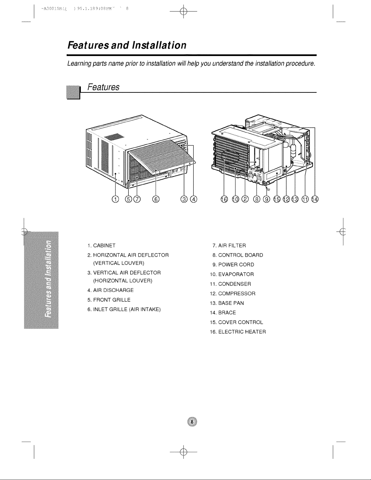
Features and InMallation
Learning parts name prior to installation will heip you understand the installation procedure.
1, CABINET
2. HORIZONTAL AIR DEFLECTOR
(VERTICAL LOUVER)
3. VERTICAL AIR DEFLECTOR
(HORIZONTAL LOUVER)
4. AIR DISCHARGE
5. FRONT GRILLE
6 INLET GRILLE (AIR INTAKE)
7 AIR FILTER
8, CONTROL BOARD
9 POWER CORD
10. EVAPORATOR
11. CONDENSER
12. COMPRESSOR
13. BASE PAN
14. BRACE
15. COVER CONTROL
16. ELECTRIC HEATER
÷
+
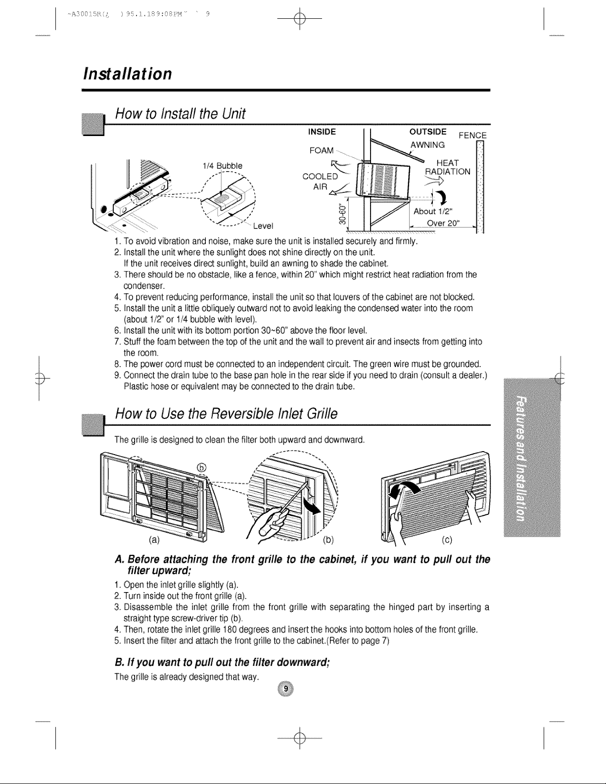
How to Install the Unit
1/4 Bubble
INSIDE OUTSIDE FENCE
AWNING
FOAM
COOLED
H EAT
1. To avoidvibrationandnoise,makesure the unit is installedsecurelyandfirmJy.
2 Installthe unit wherethe sunlight does not shinedirectlyon the unit.
If the unit receivesdirectsunlight,build anawningto shadethe cabinet.
3. Thereshouldbe noobstacle,like a fence,within20" whichmightrestrictheat radiationfromthe
condenser.
4. To preventreducingperformance,installthe unitso thatlouversof the cabinetare not blocked.
5. Installthe unit a little obliquelyoutwardnot to avoid baking the condensedwaterinto the room
(about1/2" or 1/4 bubblewith level).
6. Installthe unit withits bottomportion 30_60'' abovethe floor level
7. Stuffthe barn betweenthe top of the unit andthe wall to preventair and insects from getting into
the room.
8. The powercord mustbe connectedto an independentcircuit.The greenwire must begrounded.
9. Connectthe drain tubeto the base panhole inthe rearside if you needto drain(consulta dealer.)
Plastichoseor equivalentmaybe connectedto the draintube.
How to Use the Reversible I'flet Grille
The grilleis designedto cleanthe filter both upwardanddownward,
@ ""
(a) (b) (c)
A, Before attaching the front grille to the cabinet, if you want to puff out the
filter upward;
1. Openthe inletgrilleslightly (a).
2. Turninsideout the frontgrille (a).
3. Disassemblethe inlet grille from the front grille with separating the hinged part by inserting a
straighttype screw-drivertip (b).
4. Then,rotatethe inletgrille 180degreesand insertthe hooksinto bottomholesof the frontgrille.
5. Insertthe filterand attachthe frontgrille to the cabinet.(Referto page7)
B, If you want to pull out the filter downward;
The grilleis alreadydesignedthatway.
÷
A200SL,/;, { ) 95,:]_284_t(s:Pt_ .... ?
+
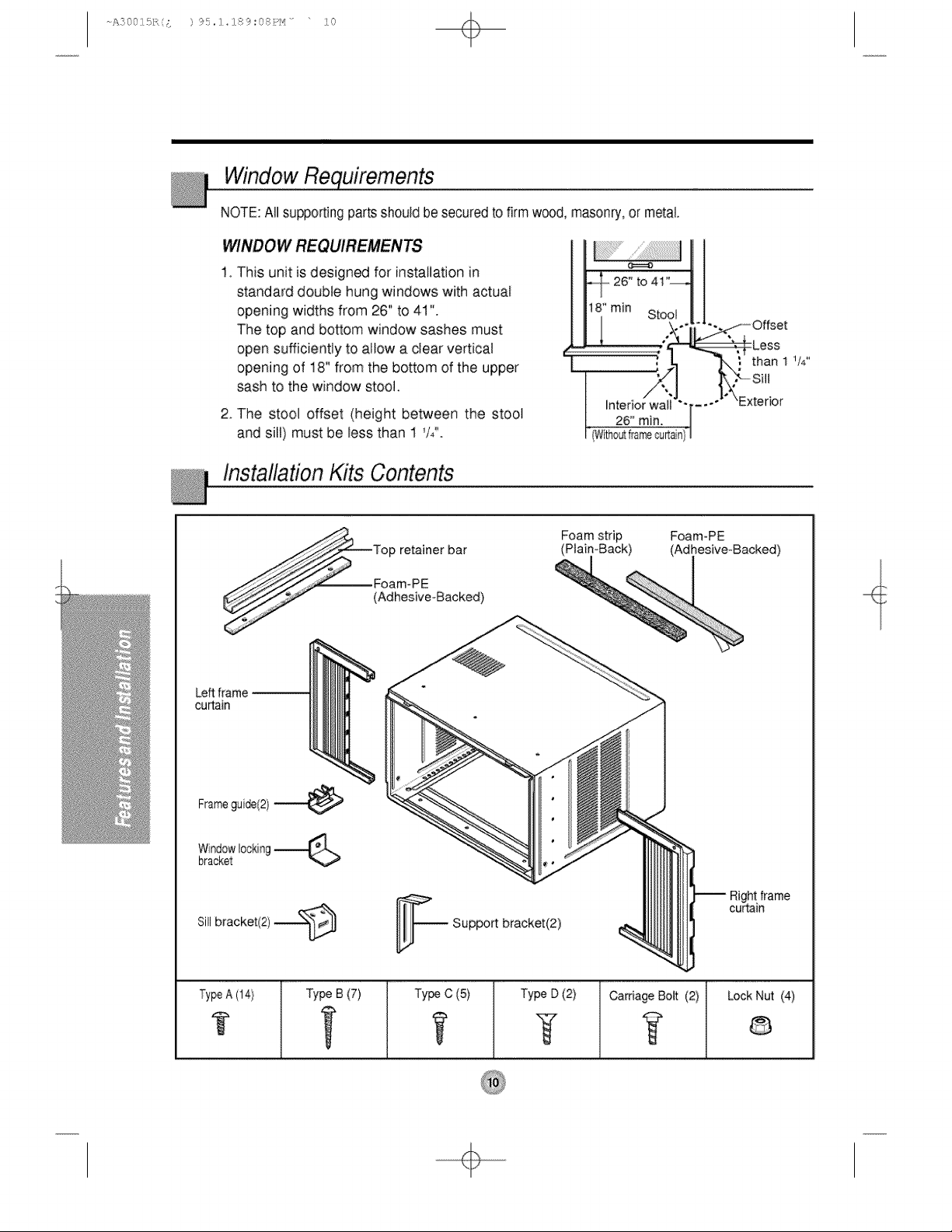
Window
NOTE: All supporting parts should be secured to firm wood, masonry, or metal
VV/NDOW REQUIREMENTS
1 This unit is designed for installation in
standard double hung windows with actual
opening widths from 26" to 41"
The top and bottom window sashes must
open sufficiently to altow a dear vertical
opening of 18" from the bottom of the upper
sash to the window stool.
2. The stooU offset (height between the stool
and sill) must be less than 1 W'.
F
interior wall
26" min.
InstallationKits Contents
-Less
than 1 1/4"
TypeA (14} TypeB(7) Type C (5)
t
Type D (2)
T
Carriage Bolt (2) Lock Nut (4)
÷
A2001£,/;, ;: ) 95,:]_284_;(s:Pt_ .... 1!2
+
Suggested Tool Requirements
I
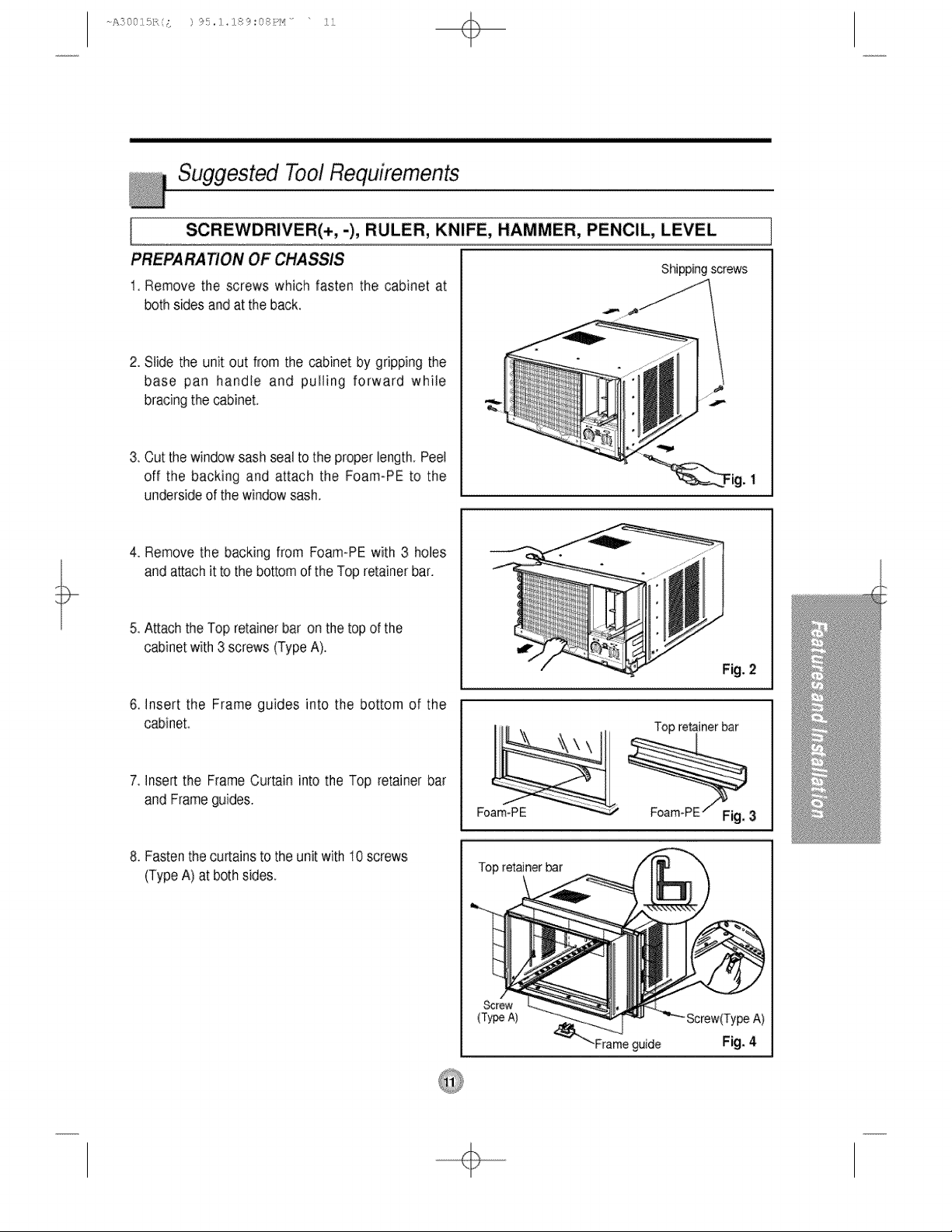
PREPA RATION OF CHASSIS
1 Remove the screws which fasten the cabinet at
both sidesand at the back.
SCREWDRIVER(+,-), RULER, KNIFE, HAMMER, PENCIL, LEVEL
Shipping screws
2. Slide the unit out from the cabinet by gripping the
base pan handle and pulling: forward while
bracingthe cabinet.
3. Cut the windowsashseal to the properlength,Peel
off the backing and attach the Foam-PE to the
undersideof the windowsash,
4. Remove the backing from Foam-PEwith 3 holes
andattachit to the bottomof the Top retainerbar.
5. Attach the Top retainerbar on the top of the
cabinetwith3 screws (TypeA).
6. Insert the Frame guides into the bottom of the
cabinet.
7. Insertthe Frame Curtain into the Top retainer bar
and Frameguides.
8. Fasten the curtains to the unit with 10 screws
(Type A) at both sides.
Fig. 2
Top retainerbar
Foam-PE
Top retainer mr
Screw
(Type A)
Screw(Ty_ A)
"Frameguide Fig;. 4
÷
+
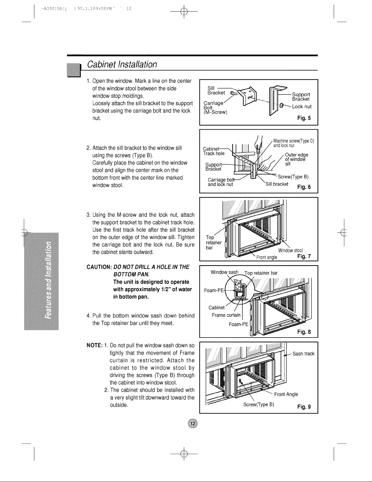
Cabinet Installation
1 Open the window. Mark a tine on the center
of the win_w stool between the side
window stop motding&
Loosety attach the sill bracket to the suppott
bracket using the carriage bolt and the Io,sk
nuL
2, Attachthe Sillbracketto the windowsill
usingthe screws(TypeB).
Cardully place the cabinetonthe window
stooland alignthecenter markonthe
bottomfrontwith the centerlinemarked
windowstool,
II II Bracket
Carfia le"
Bolt _ Look nut
(M-Screw)
Fig. 5
Cabinet---,j I [ :t
Track h
Su_
uracK
-
/Machine_rewITy_ D)
andlocknul '
/ Oute.redge
.,. / or wln_Jow
sill
Screw(TypeB)
Sill bracket
Fig. 6
3 Using the M-screw and the lock nut, attach
the support bracket to the cabinet track hole.
Use the first track hole after the sill bracket
on the outer edge of the window silt. Tighten
the carriage bolt and the lock nut. Be sure
the cabinet slants outward.
CAUTION: DO NOT DRILL A HOLE tN THE
BOTTOM PAN.
The unit is designed to operate
with approximately 1/2" of water
in bottom pan.
4_Pull the bottom window sash down behind
the Top retainerbaruntil they meet,
NOTE: 1.
Do not pullthe windowsashdown so
tightly that the movement of Frame
curtain is restricted. Attach the
cabinet to the window stoot by
driving the screws (Type B) through
the cabinetinto windowstool.
2. The cabinetshould be installed with
a veryslighttilt downwardtowardthe
outside.
retainer
bar
Window stool
Frontangle Fig, 7
Window sash op retainer bar
Frame curtain
FoamoPE
Fig, 8
FrontAngle
Screw(TypeB) Fig, 9
÷
A2001£,/;, { ) 95,:]_284_;(s:Pt_ .... !:3
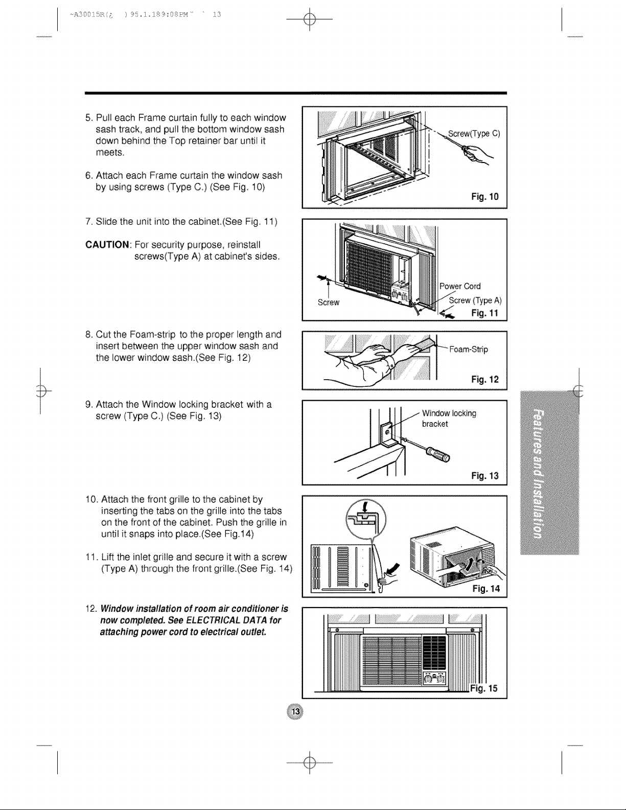
5_Pull each Frame curtain fulty to each window
sash track, and pull the bottom window sash
down behind the Top retainer bar until it
meets,
6, A_ach each Frame curtain the window sash
by using screws (Type C,) (See Fig, 10)
7. Slide the unit into the cabinet,(See Fig, 11)
CAUTION: For security purpose, reinstall
screws(Type A) at cabinet's sides,
8. Cut the Foam-strip to the proper length and
insert between the upper window sash and
the lower window sash.(See Fig. 12)
9, A_ach the Window locking bracket with a
screw (Type C,) (See Fig, t3)
10, Attach the front grille to the cabinet by
inserting the tabs on the grille into the tabs
on the front of the cabinet. Push the grille in
until it snaps into place.(See Fig,14)
11, Lift the inlet grit:leand secure it with a screw
(Type A) through the front gritle.(See Fig. 14)
12. Windowinstal/ationof roomair conditioneris
now comp/eted._e ELECTR/CALDATA for
attachingpower cord to e/ectrica/ out/et.
Fig.10
PowerCord
Fig. 11
Fig. 14
15
÷
A:}00]£,/;, { ) 95,:]_284_:(s:P_'_ .... 1!4
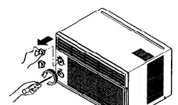
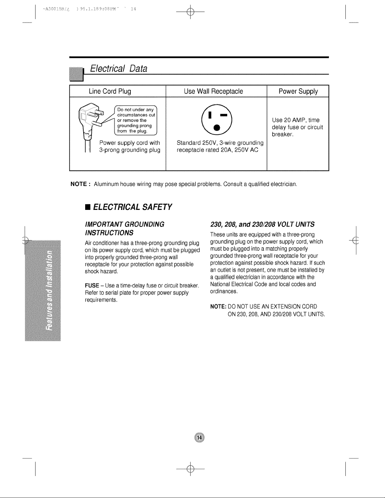
Electrical Data
Line Cord Plug Use Walt Receptacle Power Supply
i
_,, Use 20 AMP_ time
" _ding prong delay fuse or circuit
breaker
Power supply cord with o ' '
, rooo0rouoo,o0 ,o0r c% ePe 0A:W AC°
NOTE : Numinum house wiring may pose special problems. Consult a quatifiedelectrician.
• ELECTRICAL SAFETY
IMPORTANT GROUNDING
Airconditionerhas a three@ronggroundingplug
on its power supptycord, which mustbe plugged
into properiygroundedthree-prongwalt
receptaclefor your protectionagainstpossible
shockh_ard,
FUSE- Use a time-delayfuse or circuitbreaker.
Referto serial platefor properpowersupply
requirements.
230, 208, and 230/208 VOLT UNITS
Theseunitsare equippedwitha three-prong
groundingplugon the powersupplycord,which
must bepluggedinto a matchingproperly
groundedthree-prongwall receptaclefor your
protectionagainstpossibleshockhazard If such
anoutlet is not present,one mustbe instaliedby
a qualifiede_ectricianin accordancewith the
NationalElectricalCode and local codes and
ordinances
NOTE:DO NOTUSEAN EXTENSIONCORD
ON 230,208, AND230/208VOLT UNITS.
÷
A20O]£,/;, £ ) 95,:]_284_:(s:Pt_ .... 1!£
fom you for
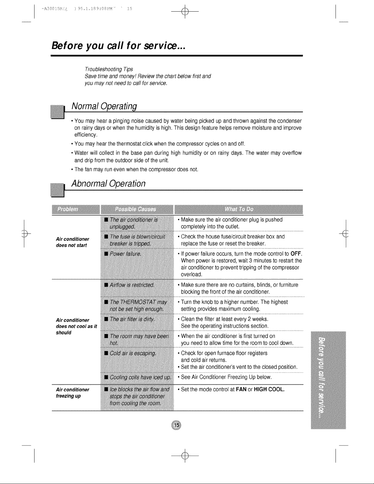
Troubleshooting Tips
Save time and money[ Review the chart below first and
you may not need to call for service.
Normal Operating
• Youmay'heara pinging noisecaused by water being picked up and thrown against the condenser
on rainy daysor when the humidityis high,Thisdesign featurehelpsremovemoistureandimprove
efficiency
• You mayhearthe thermostatclick whenthe compressorcycles on and off.
• Water will collect in the base pan during high humidityor on rainy days, The water may overflow
anddripfrom the outdoorsideof the unit,
• The fan may run evenwhen the compressordoes not,
Abnormal Operation
Air conditioner
does not start
Air conditioner
does not cool as it
should
Air conditioner
freezing up
• Makesure the air conditioner plug is pushed
compbteiy intothe outlet,
. Ch_k the housefusdcircuit breaker box and
replacethe fuseor resetthe breaker,
• if powerfailure o_urs, turn the modecontrolto OFF.
Whenpower is restored,wait3 minutesto restartthe
airconditionerto preventtrippingof the compressor
overload.
, Makesure thereare nocurtains,blinds,orfurniture
blockingthe front of the air conditioner.
• Turnthe knobto a highernumber,The highest
settingprovidesmaximumcooling,
• Cleanthe filter at least every 2 weeks.
Seethe operatinginstructionssection.
• Whenthe airconditioneris first turned on
you needto allow time for the roomto cool down.
.Checkfor open furnace floor registers
andcold air returns.
• Set the air conditioneCsvent to the closed position,
, SeeAir ConditionerFreezingUp below.
. Set the modecontrol at FANor HIGHCOOL
÷