Installation Manual
Middle Static Pressure
SOPHIA SERIES
Duct Type
CH-M09DTUI
Models:
CH-M12DTUI
CH-M18DTUI
IMPORTANT NOTE:
Read this manual carefully before installing or operating your new air conditioning unit.
Be sure to save this manual for future reference.
CH-M24DTUI CH-24LCUO
Accessories....................................................04
a. Indoor Unit Parts........................................ 07
b. Indoor Unit Installation Instructions.......08
Safety Precautions .....................................05
Outdoor Unit Installation......................... 13
a. Outdoor Unit Installation Instructions......13
b. Outdoor Unit Types and Specifications....14
c. Notes on Drilling Hole in Wall....................15
Drainpipe Installation............................... 16
Table of Contents
Installation Manual
Indoor Unit Installation
...........................07
Installation Overview ...............................06
1
2
5
3
4
6
Page 3
Refrigerant Piping Connection.......................18
A. Notes on Pipe Length and Elevation...............18
B. Refrigerant Piping Connection Instructions....19
Wiring................................................. 21
a. Outdoor Unit Wiring................... 21
b. Indoor Unit Wiring...................... 22
c. Power Specifications................... 24
Air Evacuation
................................................. 26
a. Evacuation Instructions................................. 26
b. Note on Adding Refrigerant........................ 27
Test Run.............................................28
MC MC
7
8
9
10
L N
Page 4
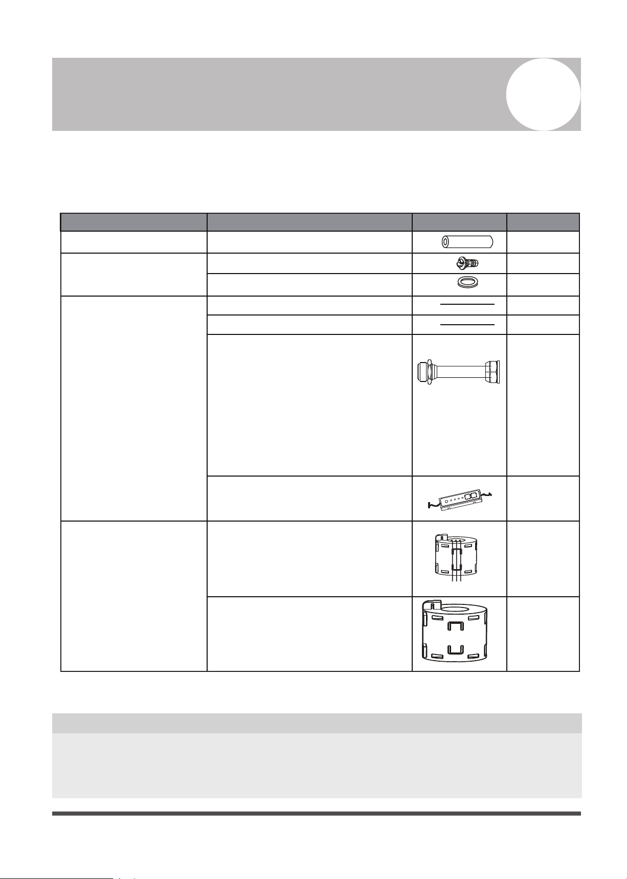
Accessories
1
The air conditioning system comes with the following accessories. Use all of the installation parts
and accessories to install the air conditioner. Improper installation may result in water leakage,
electrical shock and fire, or cause the equipment to fail.
QUANTITY
SHAPENAME
Soundproof / insulation sheath
2
1
1
1
1
1
Tubing & Fittings
Others
Installation manual
Transfer connector (some models)
(Ø0.375in-Ø0.375in)/(Ø9.52-Ø9.52)
(Packed with the indoor unit )
NOTE: Pipe size may differ from
appliance to appliance. To meet
different pipe size requirements,
sometimes the pipe connections
need a transfer connector installed
on the outdoor unit.
Component of display control
unit (some models)
1
Owner‘s manual
Drain joint (some models)
Seal ring (some models)
Drainpipe Fittings
(for cooling & heating)
Optional accessories
There are two types of remote controls: wired and wireless.
Select a remote control based on customer preferences and requirements and install in an
appropriate place.
Refer to catalogues and technical literature for guidance on selecting a suitable remote control.
•
1
1
EMC Magnetic
Ring (some
models)
Magnetic ring (wrap the electric
wires S1 & S2 (P & Q & E) around
the magnetic ring twice)
Magnetic ring
(Hitch on the connective cable
between the indoor unit and
outdoor unit after installation.)
S1&S2(P&Q&E)
Page 5
Safety Precautions
2
Read Safety Precautions Before Installation
Incorrect installation due to ignoring instructions can cause serious damage or injury.
The seriousness of potential damage or injuries is classified as either a WARNING or CAUTION.
WARNING
• Carefully read the Safety Precautions before installation.
• In certain functional environments, such as kitchens, server rooms, etc., the use of specially
designed air-conditioning units is highly recommended.
• Only trained and certified technicians should install, repair and service this air
conditioning unit.
Improper installation may result in electrical shock, short circuit, leaks, fire or other damage to
the equipment and personal property.
• Strictly follow the installation instructions set forth in this manual.
Improper installation may result in electrical shock, short circuit, leaks, fire or other damage to
the equipment.
• Before you install the unit, consider strong winds, typhoons and earthquakes that might affect
your unit and locate it accordingly. Failure to do so could cause the equipment to fail.
• After installation, ensure there are no refrigerant leaks and that the unit is operating properly.
Refrigerant is both toxic and flammable and poses a serious health and safety risk.
• This appliance is not intended for use by persons (including children) with reduced physical,
sensory or mental capabilities, or lack of experience and knowledge, unless they have been
given supervision or instruction concerning use of the appliance by a person responsible for
their safety. Children should be supervised to ensure that they do not play with the appliance.
• The appliance (indoor units) shall not be installed in the laundry.
Note about Fluorinated Gasses
1. This air-conditioning unit contains fluorinated gasses. For specific information on the type of gas
and the amount, please refer to the relevant label on the unit itself.
2. Installation, service, maintenance and repair of this unit must be performed by a certified
technician.
3. Product uninstallation and recycling must be performed by a certified technician.
4. If the system has a leak-detection system installed, it must be checked for leaks at least every 12
months.
5.
When the unit is checked for leaks, proper record-keeping of all checks is strongly recommended.
Failure to observe a warning may result in death. The appliance must be installed in
accordance with national regulations.
Failure to observe a caution may result in injury or equipment damage.
WARNING
CAUTION
Page 6
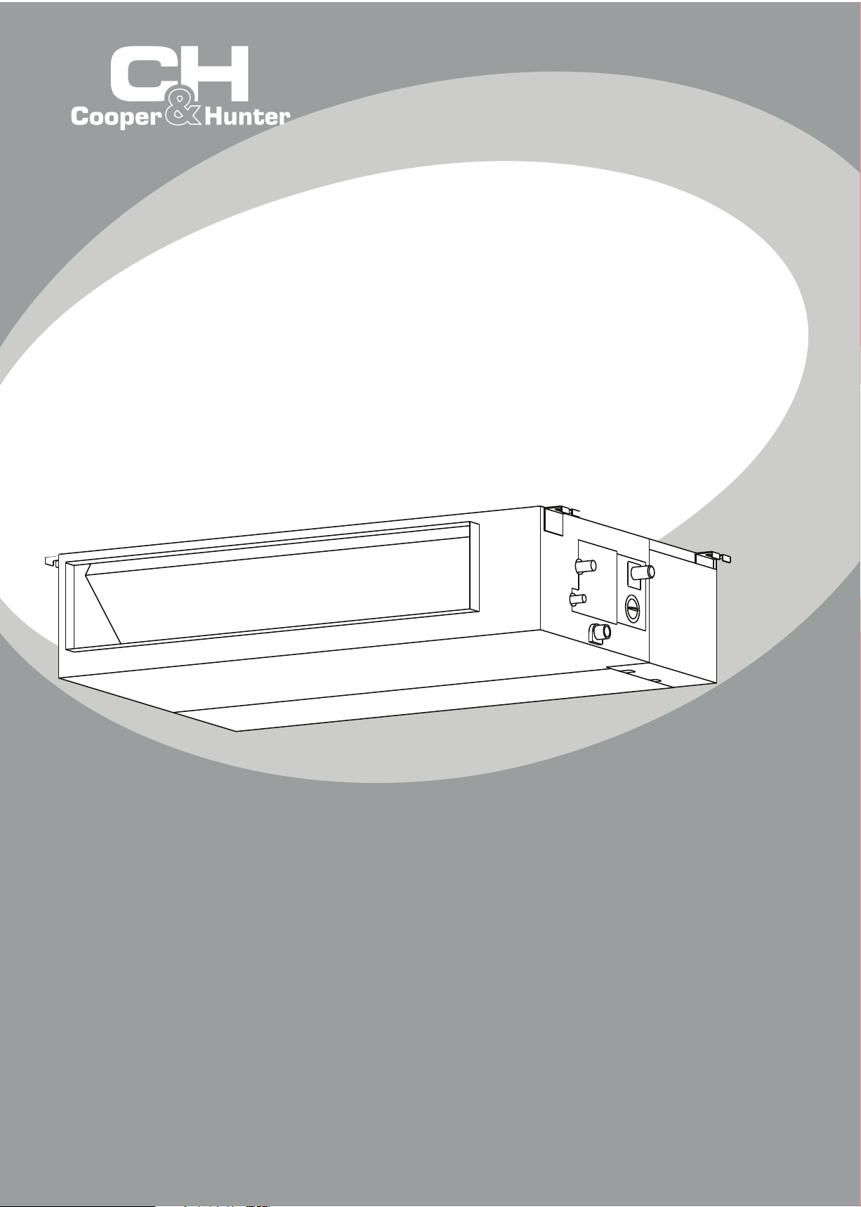
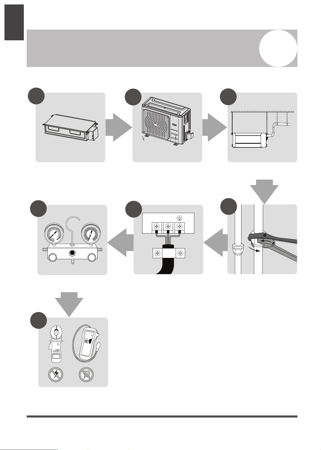
Installation Overview
3
Unit Installation
Overview
L N
1
2
3
4
5
MC MC
6
7
Install the indoor unit
(Page 7)
INSTALLATION ORDER
Install the outdoor unit
(Page 13)
Install the drainpipe
(Page 16)
Evacuate the refrigeration system
(Page 25)
Connect the wires
(Page 21)
Connect the refrigerant pipes
(Page 18)
Perform a test run
(Page 27)
Page 7
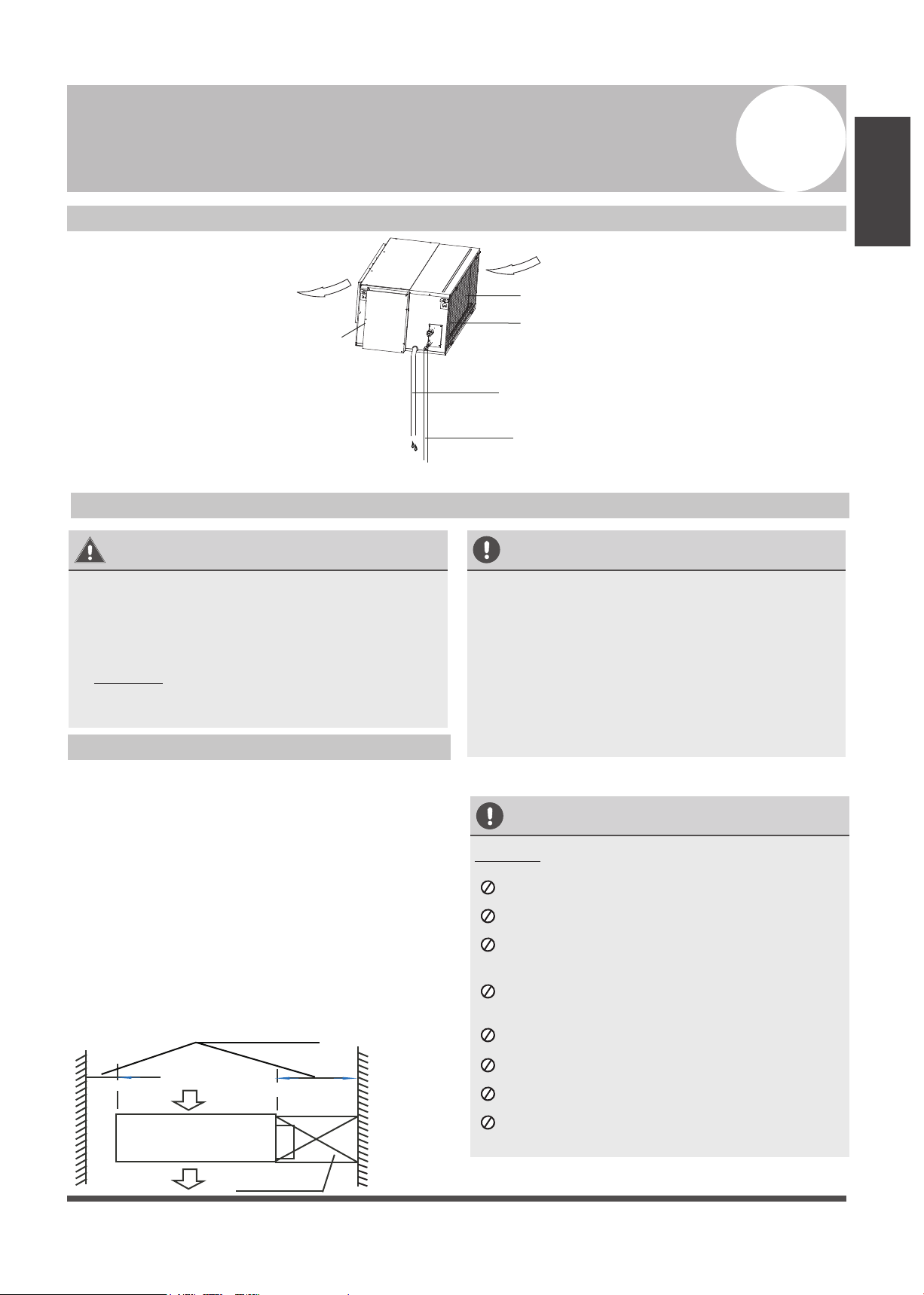
Indoor Unit Installation
4
Indoor Unit
Installation
Indoor Unit Parts
WARNING
• Securely install the indoor unit on a structure
that can sustain its weight. If the structure is
too weak, the unit may fall causing personal
injury, unit and property damage, or even
death
• DO NOT install the indoor unit in a bathroom
or laundry room as excessive moisture can
short the unit and corrode the wiring.
CAUTION
• Install the indoor and outdoor units, cables
and wires at least 3.2’ (1m) from televisions
or radios to prevent static or image
distortion. Depending on the appliances, a
3.2’ (1m) distance may not be sufficient.
• If the indoor unit is installed on a metal
part of the building, it must be grounded.
Install the indoor unit at least 7.87’(2.4m)
from the floor.
Indoor Unit Installation Instructions
Step 1: Select installation location
The indoor unit should be installed in a location
that meets the following requirements:
Enough room for installation and maintenance.
Enough room for the connecting pipe and
drainpipe.
The ceiling is horizontal and its structure can
sustain the weight of the indoor unit.
The air inlet and outlet are not impeded.
The airflow can fill the entire room.
There is no direct radiation from heaters.
CAUTION
DO NOT install the unit in the following locations:
Where oil drilling or fracking is taking place
Coastal areas with high salt content in the air
Areas with caustic gases in the air, such
as near hot springs
Areas with power fluctuations, such as
factories
Enclosed spaces, such as cabinets
Areas with strong electromagnetic waves
Areas that store flammable materials or gas
Rooms with high humidity, such as
bathrooms or laundry rooms
Fig. 4.2
√
√
√
√
√
√
Safety Precautions
Fig. 4.1
Air outlet
Air inlet
Drain hose
Refrigerant connecting pipe
Electric control cabinet
Air filter(inside air-in grill)(optional)
Heat exchanger
Maintenance roomage
checking orifice
23X23 in
23 in or more
20 in or more
Air outlet
Air inlet
•
Page 8
Indoor Unit
Installation
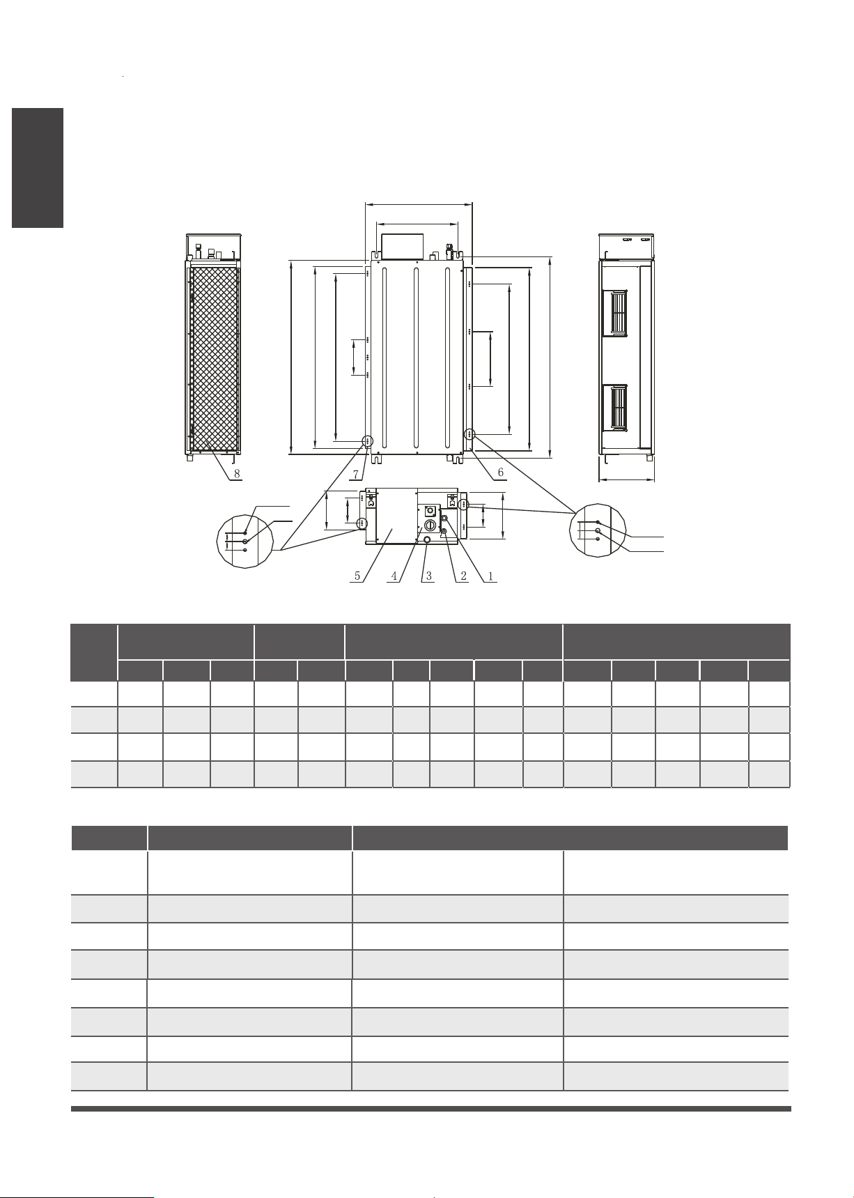
Table.4-1
(unit: in/mm)
MODEL
(Btu/h)
Outline dimension
A B C
24K
35.4/900 10.6/27020.6/525
30K~36K 43.7/1110 10.6/27020.6/525
45K~60K 47.2/1200 15/38024.6/625
55K~60K 55.1/1400 17.3/44033.8/858
size of
mounted lug
D E F
36.8/936 33.2/84415.6/397
45/1146 41.5/105415.6/397
48.6/1236 39.3/100019.5/495
56.5/1436 46.7/118827.5/700
7.2/185
7.2/185
10/253
15/385
I
30.7/7806.3/160
37.8/9608.6/220
35.4/90010.6/270
39.3/100020/500
J
G
H
4.7/120
4.7/120
6.7/170
11/280
K
33.5/851
41.7/1061
45/1145
46.7/1188
8.9/226
8.9/226
13.1/334
12.8/325
N
26.2/6658.4/215
34.4/87512.4/315
36.4/92512.8/325
39.3/100020/500
O
L
M
4.3/110
4.3/110
5.1/130
11/280
Name
fixed-frequency
Gas pipe connection Ø5/8” (24~36K units)
Ø3/4” (48~60K units)
Liquid pipe connection
Ø3/8”
Drain pipe connection OD Ø1” ID Ø3/4”
Drain pipe connection
Using drain pump (optional)
Power supply connection
_
Air inlet duct flange
_
Air outlet duct flange
_
Number
1
2
3
4
5
6
7
The size of installation for indoor unit following the Fig.4-3, This unit has installed with air filter.
Fig. 4.3
D
A
H
I
F
M
N
K
E
J
G
O
L
C
B
air inlet opening size
(symmetry of air inlet opening)
air outlet opening size
(symmetry of air outlet opening)
Air filter
optional
inverter
Ø5/8”
Ø3/8”
OD Ø1” ID Ø3/4”
Using drain pump (optional)
_
_
_
optional
8
Table.4-2
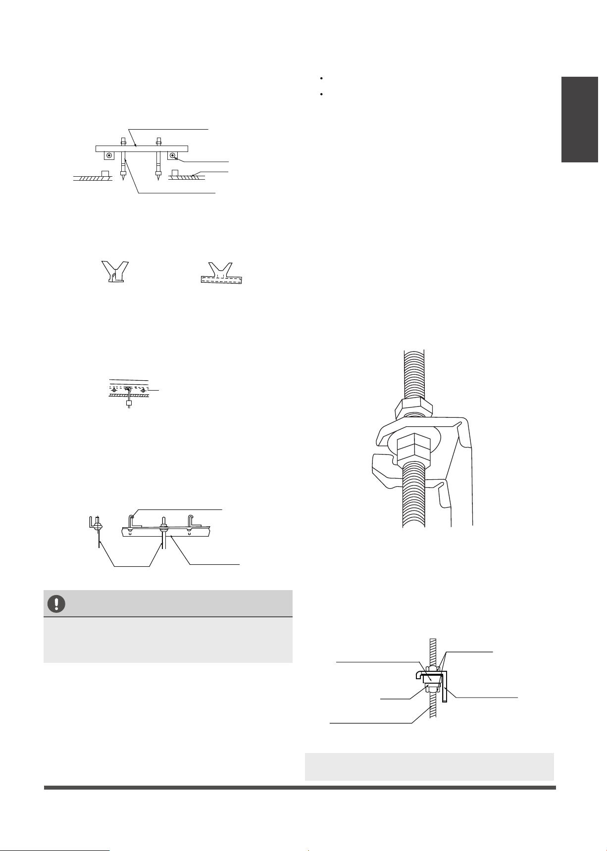
Step 2: Hang indoor unit.
1. Please refer to the following diagrams to locate the four positioning screw bolt holes on the
ceiling. Be sure to mark the paces where you will drill ceiling hook holes.
3/8” 3/8”
2-Φ
Φ
NOTE: 14 groups all around
NOTE: 12 groups all around
Φ
3/16”
2-Φ1/8”
3/16”
1/8”
3/8” 3/8”
Page 9
Indoor Unit
Installation
Cut off the roof beam.
Strengthen the point at which the cut
was made. Consolidate the roof beam.
Fig. 4.6
Fig. 4.7
Original concrete bricks
Use an embedding screw bolt, crock, and stick
harness.(See Fig.4.6)
Steel roof beam structure
Install and use the supporting steel angle.
(See Fig.4.7)
Fig. 4.4
Wood
Place the wood mounting across the roof beam,
then install the hanging screw bolts.(See Fig.4.4)
Wood mounting
Roof beam
Hanging screw bolts
Ceiling
Fig. 4.5
New concrete bricks
Inlay or embed the screw bolts. (See Fig.4.5)
(Blade shape insertion)
(Slide insertion)
Steel bar
Embedding screw bolt
(Pipe hanging and embedding screw bolt)
Hanging screw bolt
Hanging bolts
Supporting
angle steel
Fig. 4.9
Screw nut
Washer
Hanging screw bolt
Overhang part
Shockproof cushion
NOTE: Confirm the minimum drain tilt is 1/100 or
more.
CAUTION
The unit body must be completely aligned with
the hole. Ensure that the unit and the hole are
the same size before moving on.
2. Install and fit pipes and wires after you have
finished installing the main body.When
choosing where to start, determine the
direction of the pipes to be drawn out.
Especially in cases where there is a ceiling
involved, align the refrigerant pipes, drain
pipes, and indoor and outdoor lines with their
connection points before mounting the unit.
3.
Install hanging screw bolts.
4. After you select an installation location,align
the refrigerant pipes, drain pipes, as well as
indoor and outdoor wires with their
connection points before mounting the unit.
5. Drill 4 holes 4” (10cm) deep at the ceiling
hook positions in the internal ceiling. Be sure
to hold the drill at a 90° angle to the ceiling.
6. Secure the bolt using the washers and nuts
provided.
7. Install the four suspension bolts.
8. Mount the indoor unit with at least two
people to lift and secure it. Insert suspension
bolts into the unit’s hanging holes. Fasten
them using the washers and nuts provided.
(See Fig. 4.8).
9. Mount the indoor unit onto the hanging
screw bolts with a block. Position the
indoor unit flat using a level indicator to
prevent leaks. (See Fig. 4.9).
Fig. 4.8
Page 10
Indoor Unit
Installation
•
Fig. 4.10
Fig. 4.12
Fig. 4.13
Fig. 4.14
Fig. 4.15
Fig. 4.16
Fig. 4.17
Fig. 4.18
Fig. 4.11
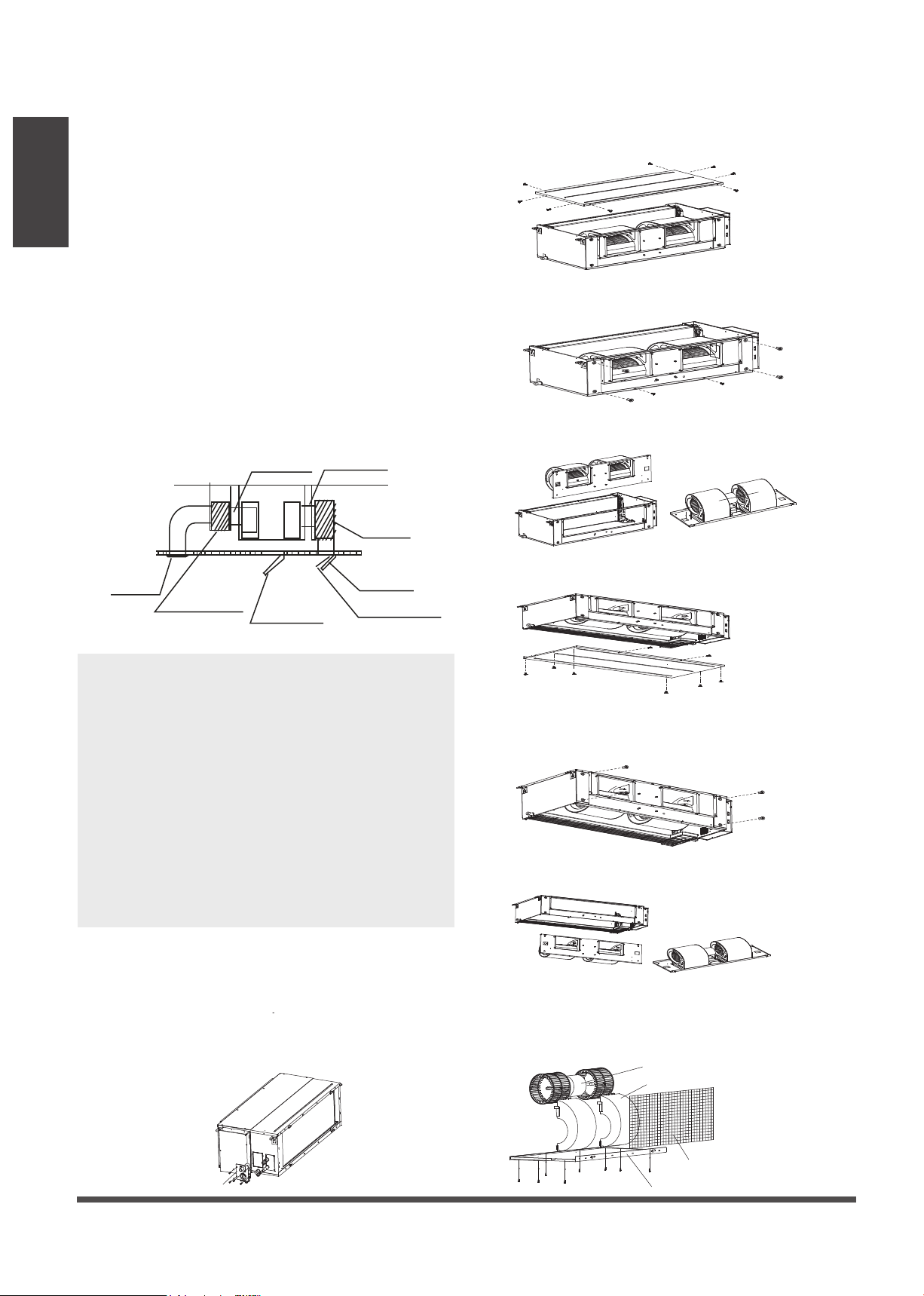
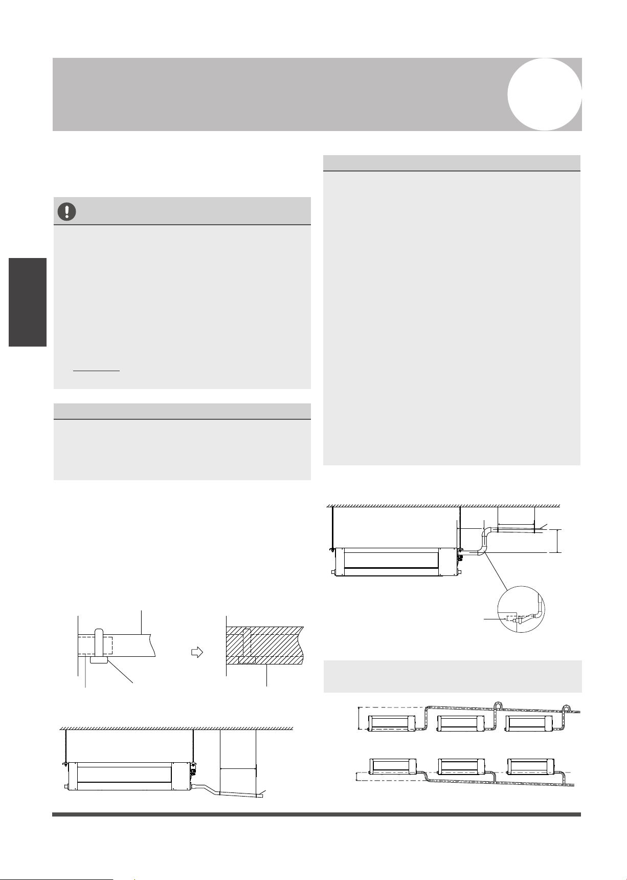
Step 4: Duct and accessories installation
NOTE: 1. Do not put the connecting duct
weight on the indoor unit.
2. When connecting the duct, use an
nonflammable canvas tie-in to prevent
vibrating.
3. When connecting duct, install in place prone
to takedown for maintenance.
4. Change the fan motor static pressure
corresponding to external duct static pressure.
5. If installed in place like meeting room where
noise is easy to be perceived, design isolation
booth and internal duct underlayer to muffle
the duct system and weaken the air
encounter noise in the duct.
1. The air inlet and air outlet duct should be far
enough apart enough to prevent air outlet
entering Air Inlet.
Step 3: Diagrammatic sketch for installing
the main body
Installing the dust proof net and canvas air
passage
2. There is dust filter on the indoor unit.
3. Please attach the outside air duct to the indoor
air outlet/inlet flange by using the type
ST3.9 x 10 screw.
4. Connect the duct according to the following
diagram:
Canvas tie-in Canvas tie-in
Air outlet
Isolation booth
Isolation booth
checking orifice
Air inlet
Air dust filter
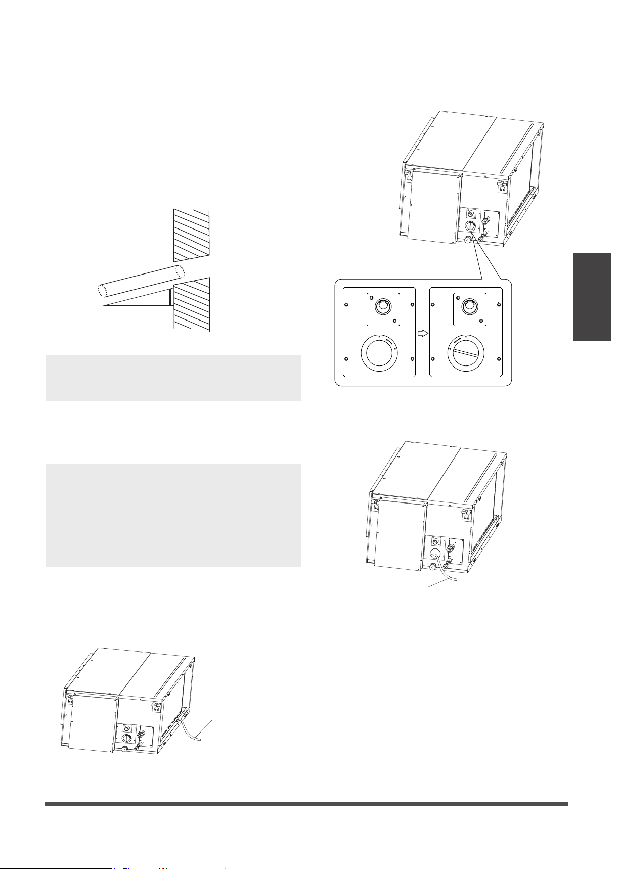
1. Install the dust proof net according to the
installation manual;
There are three methods:
1: Remove the front side plate from the top.
• Remove the top cover as shown.
3: Repair it directly (only applicable to plastic
scroll and fan wheel)
2: Remove the front side plate from the bottom.
• Remove the bottom base as shown.
2. Install the canvas air passage underneath the
dust proof net.
Step 5: Motor and drain pump maintenance
Pump maintainance:
Remove four screws from the drain pump.
Unplug the pump power supply and water
level switch cable.
Detach the pump.
1.
2.
3.
Pump
Motor maintain:
Loosen the four bolts and two screws which
used to fasten the front side plate.
•
Loosen the four bolts and two screws which
used to fasten the front side plate (Be
careful, the front side plate may fall down)
•
Remove the cord of motor, take off the
front side plate and repair the motor.
•
Remove the cord of motor, take off the
front side plate and repair the motor.
• Take off the chassis assembly and filter .
• Take off the volute. • Take off the motor.
Motor
Volute
Filter
Chassis assembly
Page 11
Outdoor Unit
Installation
Outdoor Unit Installation
Outdoor Unit Installation Instructions
Step 1: Select installation location.
The outdoor unit should be installed in the
location that meets the following requirements:
Place the outdoor unit as close to the indoor
unit as possible.
Ensure that there is enough room for
installation and maintenance.
The air inlet and outlet must not be
obstructed or exposed to strong wind.
Ensure the location of the unit will not be
subject to snowdrifts, accumulation of
leaves or other seasonal debris. If possible,
provide an awning for the unit. Ensure the
awning does not obstruct airflow.
The installation area must be dry and well
ventilated.
There must be enough room to install the
connecting pipes and cables and to access
them for maintenance.
The area must be free of combustible gases
and chemicals.
The pipe length between the outdoor and
indoor unit may not exceed the maximum
allowable pipe length.
If possible, DO NOT install the unit where it
is exposed to direct sunlight.
If possible, make sure the unit is located far
away from your neighbors’ property so that
the noise from the unit will not disturb them.
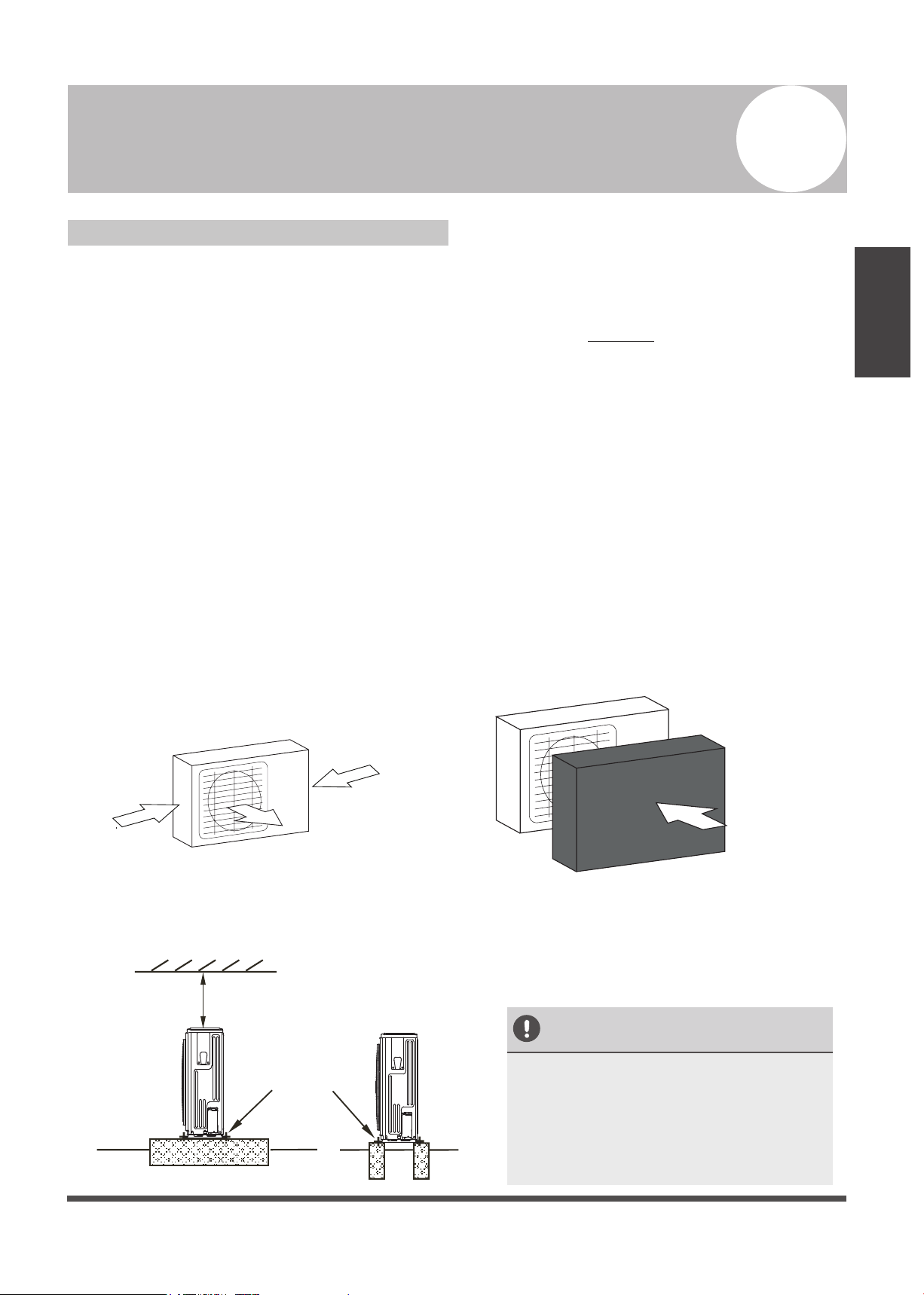
If the location is exposed to strong winds (for
example: near a seaside), the unit must be
placed against the wall to shelter it from the
wind. If necessary, use an awning. (See Fig.
5.1 & 5.2)
Install the indoor and outdoor units, cables
and wires at least 1 meter from televisions or
radios to prevent static or image distortion.
Depending on the radio waves, a 1 meter
distance may not be enough to eliminate all
interference.
Strong wind
Strong wind
Strong wind
Fig. 5.1
Fig. 5.2
Step 2: Install outdoor unit.
Fix the outdoor unit with anchor bolts (M10)
>23.6” /60cm
Fix with bolts
CAUTION
• Be sure to remove any obstacles that
may block air circulation.
• Make sure you refer to Length
Specifications to ensure there is
enough room for installation and
maintenance.
Fig. 5.3
5
√
√
√
√
√
√
√
√
√
√
√
√
Page 12
Outdoor Unit
Installation
>47”/120cm
Air Outlet
(Wall or obstacle)
H
D
W
>11.8” /30cm
Air inlet
Air inlet
Air inlet
Air inlet
(Wall or obstacle)
>11.8” /30cm
>11.8” /30cm
>11.8” /30cm
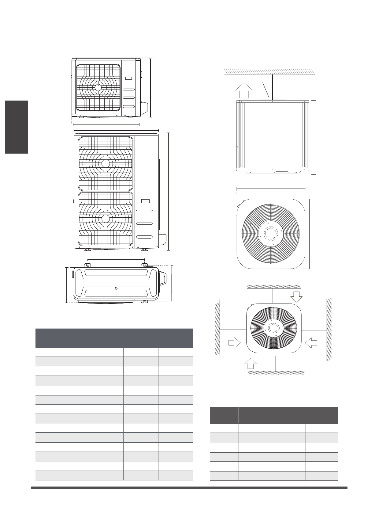
Table 5.1: Length Specifications of Split
Type Outdoor Unit (unit: mm/inch)
Table 5.2: Length Specifications of Vertical
Discharge Outdoor Unit (unit: mm/inch)
MODEL
DIMENSIONS
W HD
18 25/63321.8/55421.8/554
24 25/63321.8/55421.8/554
36 29.8/75921.8/55421.8/554
36 25/63323.6/60023.6/600
48 29.8/75928/71028/710
60 33/84328/71028/710/
Split Type Outdoor Unit
(Refer to Fig 5.4, 5.5, 5.6, 5.10 and Table 5.1)
Vertical Discharge Type Outdoor Unit
(Refer to Fig 5.7, 5.8, 5.9 and Table 5.2)
Fig. 5.7
Fig. 5.8
Fig. 5.9
Fig. 5.6
Fig. 5.5
A
B
D
W
H
W
H
Fig. 5.4
Outdoor Unit Dimensions
W x H x D
Mounting Dimensions
Distance A Distance B
29.9x23.2x11.2 (760x590x285) 20.85 (530) 11.4 (290)
31.9x22x12.2 (810x558x310) 21.6 (549) 12.8 (325)
33.27x27.5x12.6 (845x700x320) 22 (560) 13.2 (335)
35.4x33.85x12.4 (900x860x315) 23.2 (590) 13.1 (333)
37.2x31.9x15.55 (945x810x395) 25.2 (640) 15.95 (405)
38.98x38x13.58 (990x965x345) 24.58 (624) 14.4 (366)
37.24x31.9x16.53 (946x810x420) 26.5 (673)
15.87 (403)
37.24x31.9x16.14 (946x810x410) 26.5 (673)
15.87 (403)
37.5x52.5x16.14 (952x1333x410) 24.96 (634)
15.9 (404)
37.5x52.5x16.3 (4952x1333x415) 24.96 (634)
15.9 (404)
33.27x27.6x14.3 (845x702x363)
21.26 (540)
13.8 (350)
36.93x53.9x15.43 (938x1369x392) 24.96 (634) 15.9 (404)
35.4x46x13.8 (900x1170x350) 23.2 (590) 14.88 (378)
31.5x21.8x13.1 (800x554x333) 20.24 (514) 13.39 (340)
Page 13
Outdoor Unit
Installation
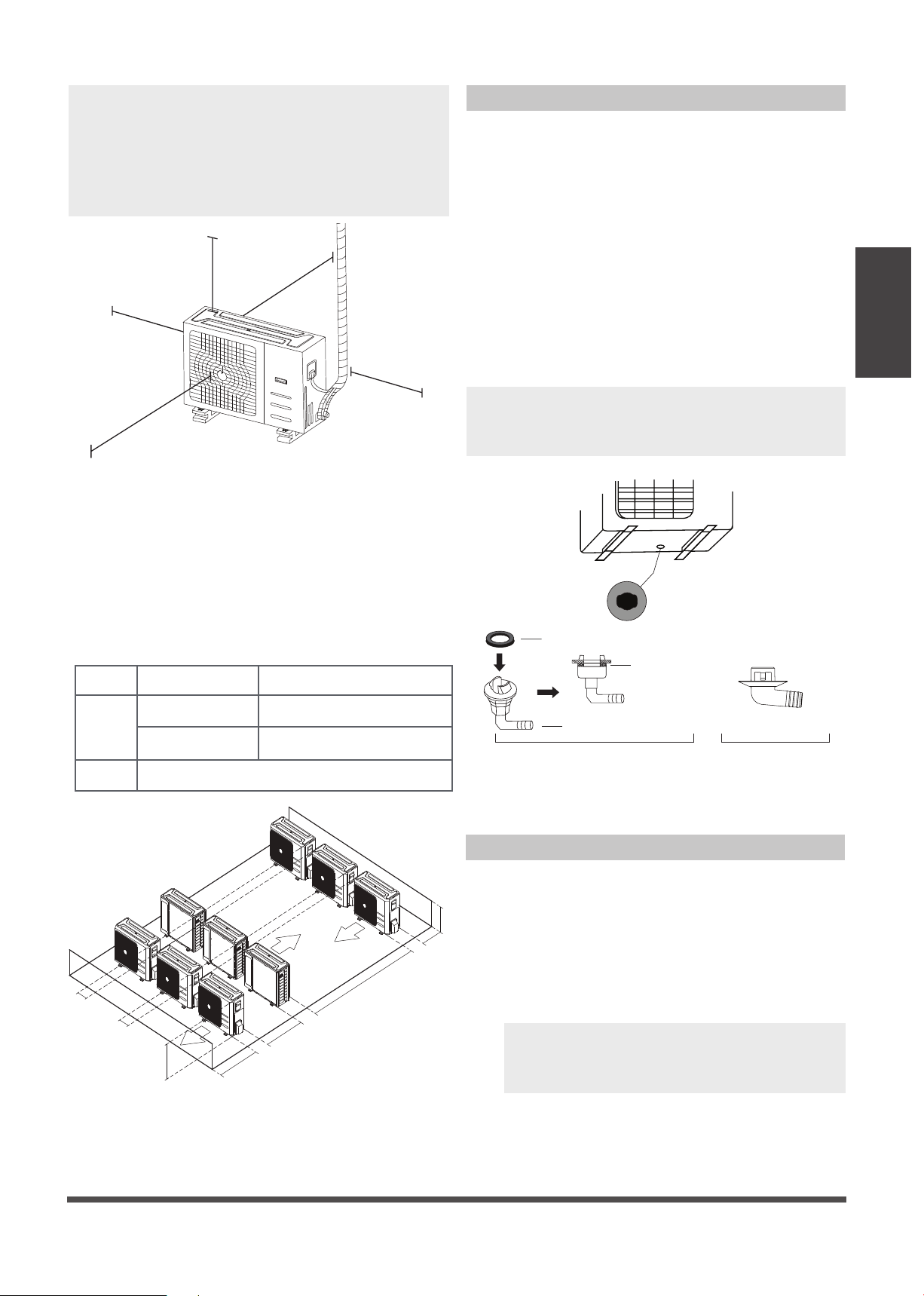
NOTE: The minimum distance between the
outdoor unit and walls described in the
installation guide does not apply to airtight
rooms. Be sure to keep the unit unobstructed
in at least two of the three directions (M, N, P)
(See Fig. 5.10)
M
N
P
11.8” / 30 cm from back wall
23.6” / 60 cm on right
23.6” / 60 cm on right
11.8” / 30 cm on left
78” / 200 cm in front
Fig. 5.10
Drain Joint Installation
Before bolting the outdoor unit in place, you
must install the drain joint at the bottom of the
unit. (See Fig. 5.12)
1. Fit the rubber seal on the end of the drain
joint that will connect to the outdoor unit.
2. Insert the drain joint into the hole in the
base pan of the unit.
3. Rotate the drain joint 90° until it clicks in
place facing the front of the unit.
4. Connect a drain hose extension (not
included) to the drain joint to redirect water
from the unit during heating mode.
NOTE: Make sure the water drains to a safe
location where it will not cause water damage
or a slipping hazard.
Seal
Drain joint
(A) (B)
Base pan hole of
outdoor unit
Seal
Fig. 5.12
Notes On Drilling Hole In Wall
You must drill a hole in the wall for the
refrigerant piping, and the signal cable that will
connect the indoor and outdoor units.
1. Determine the location of the wall hole
based on the location of the outdoor unit.
2. Using a 2.5” (65 mm) core drill, drill a hole
in the wall.
NOTE: When drilling the wall hole, make
sure to avoid wires, plumbing, and other
sensitive components.
3. Place the protective wall cuff in the hole.
This protects the edges of the hole and will
help seal it when you finish the installation
process.
Fig. 5.11
L
H
118” / 300 cm or more
A
23.6” / 60 cm
or more
59” / 150 cm
or more
9.8” / 25 cm
or more
9.8” / 25 cm
or more
Rows of series installation
L ≤ H
L ≤ 1/2H
L A
9.8”
/
25 cm or more
1/2H < L ≤ H
11.8”
/
30 cm or more
L > H Can not be installed
Table 5.3 The relations between H, A and L
are as follows.
Page 14
Drainpipe
Installation
NOTE ON DRAINPIPE INSTALLATION
• When using an extended drainpipe, tighten
the indoor connection with an additional
protection tube to prevent it from pulling
loose.
• The drainpipe should slope downward at a
gradient of at least 1/50 to prevent water
from flowing back into the air conditioner.
• To prevent the pipe from sagging, space
hanging wires every 39-59”(1-1.5m).
• If the outlet of the drainpipe is higher than
the body’s pump joint, provide a lift pipe for
the exhaust outlet of the indoor unit. The
lift pipe must be installed no higher than
21.7” (55cm) from the ceiling board and
the distance between the unit and the lift
pipe must be less than 7.9” (20cm).
Incorrect installation could cause water to
flow back into the unit and flood.
• To prevent air bubbles, keep the drain hose
level or slightly tiled up (<3”
/ 75mm).
Fig. 6.3
The drainpipe is used to drain water away from
the unit. Improper installation may cause unit
and property damage.
CAUTION
• Insulate all piping to prevent condensation,
which could lead to water damage.
• If the drainpipe is bent or installed
incorrectly, water may leak and cause a
water-level switch malfunction.
• In HEAT mode, the outdoor unit will
discharge water. Ensure that the drain hose
is placed in an appropriate area to avoid
water damage and slippage.
• DO NOT pull the drainpipe forcefully. This
could disconnect it.
NOTE ON PURCHASING PIPES
Installation requires a polyethylene tube
(exterior diameter = 1.5”, interior
diameter = 1.25”), which can be obtained at
your local hardware store or dealer.
Indoor Drainpipe Installation
Install the drainpipe as illustrated in Figure 6.2.
1.
2.
Drainpipe
connecting port
Drain hose
Pipe clasp
Insulation
Fig. 6.1
Drainpipe Installation
39-59”
<7.9”
)
”7.12
<
Fig. 6.2
Lean over 1/50
39-59”
Drainpipe installation for units with a pump
Lean over 1/50
Ceiling
Ceiling
3”
6
Cover the drainpipe with heat insulation to
prevent condensation and leakage.
Attach the mouth of the drain hose to the
unit’s outlet pipe. Sheath the mouth of the
hose and clip it firmly with a pipe clasp.
(Fig 6.1)
NOTE: When connecting multiple drainpipes,
install the pipes as shown in Fig 6.4.
20.8”
4”
Fig. 6.4
Drainage test
Check that the drainpipe is unhindered.
This test should be performed on newly built
houses before the ceiling is paved.
The unit with pump.
The unit without pump.
1. Remove the test cover.
Fill the water pan with 2.11 quart of water.
2. Turn on the unit in COOLING mode. You will
hear the drain pump.Check whether the
water is discharged properly (a 1-minute lag
is possible, depending on the length of the
drain pipe). Check whether water leaks from
the joints.
3. Turn off the air conditioner and put the cap
back on.
3. Using a 2.5” (65-mm) core drill, drill a hole in
the wall. Make sure that the hole is drilled at a
slight downward angle, so that the outdoor
end of the hole is lower than the indoor end
by about 0.5” (12mm). This will ensure proper
water drainage (See Fig. 6.5). Place the
protective wall cuff in the hole. This protects
the edges of the hole and will help seal it
when you finish the installation process.
Wall
IndoorOutdoor
≈ 12mm / 0.5 inch
Fig. 6.5
NOTE: When drilling the wall hole, make sure
to avoid wires, plumbing, and other sensitive
components.
4. Pass the drain hose through the wall hole.
Make sure the water drains to a safe location
where it will not cause water damage or a
slipping hazard.
NOTE: The drainpipe outlet should be at least
1.9” (5cm) above the ground. If it touches the
ground, the unit may become blocked and
malfunction. If you discharge the water directly
into a sewer, make sure that the drain has a U
or S pipe to catch odors that might otherwise
come back into the house.
Page 15
Fig.6.7
Fig.6.8
Fig.6.6
Fill the water pan with 2.11 quart of water.
Check that the drainpipe is unhindered.
Drainpipe
Installation
Stow tube
Test cap
C
L
O
S
E
D
O
P
E
N
C
L
O
S
E
D
O
P
E
N
Stow tube
Page 16
Refrigerant Piping
Connection
Refrigerant Piping Connection
Safety Precautions
WARNING
• All field piping must be completed by a
licensed technician and must comply with
the local and national regulations.
• When the air conditioner is installed in a
small room, measures must be taken to
prevent the refrigerant concentration in the
room from exceeding the safety limit in the
event of refrigerant leakage. If the
refrigerant leaks and its concentration
exceeds its proper limit, hazards due to lack
of oxygen may result.
• When installing the refrigeration system,
ensure that air, dust, moisture or foreign
substances do not enter the refrigerant
circuit. Contamination in the system may
cause poor operating capacity, high
pressure in the refrigeration cycle, explosion
or injury.
• Ventilate the area immediately if there is
refrigerant leakage during the installation.
Leaked refrigerant gas is both toxic and
flammable. Ensure there is no refrigerant
leakage after completing the installation
work.
Notes On Pipe Length and Elevation
Ensure that the length of the refrigerant pipe, the
number of bends, and the drop height between
the indoor and outdoor units meets the
requirements shown in Table 7.1:
Table 7.1: The Maximum Length And Drop
Height Based on Models. (Unit: ft/m)
Type of model Capacity
(Btu/h)
Length of
piping
Maximum drop
height
North America,
Australia and the
eu frequency
conversion Split
Type
<15K 82/25 32.8/10
≥15K - <24K 98.4/30 65.6/20
≥24K - <36K 164/50 82/25
≥36K - ≤60K 213/65 98.4/30
Other Split Type
12K 49/15 26/8
18K-24K 82/25 49/15
30K-36K 98.4/30 65.6/20
42K-60K 164/50 98.4/30
7
Page 17
Refrigerant Piping
Connection
Refrigerant Piping Connection Instructions
CAUTION
• The branching pipe must be installed
horizontally. An angle of more than 10° may
cause malfunction.
• DO NOT install the connecting pipe until
both indoor and outdoor units have been
installed.
• Insulate both the gas and liquid piping to
prevent water leakage.
Step1: Cut pipes
When preparing refrigerant pipes, take extra
care to cut and flare them properly. This will
ensure efficient operation and minimize the
need for future maintenance.
1. Measure the distance between the indoor
and outdoor units.
2. Using a pipe cutter, cut the pipe a little
longer than the measured distance.
CAUTION
DO NOT deform pipe while cutting. Be extra
careful not to damage, dent, or deform the pipe
while cutting. This will drastically reduce the
heating efficiency of the unit.
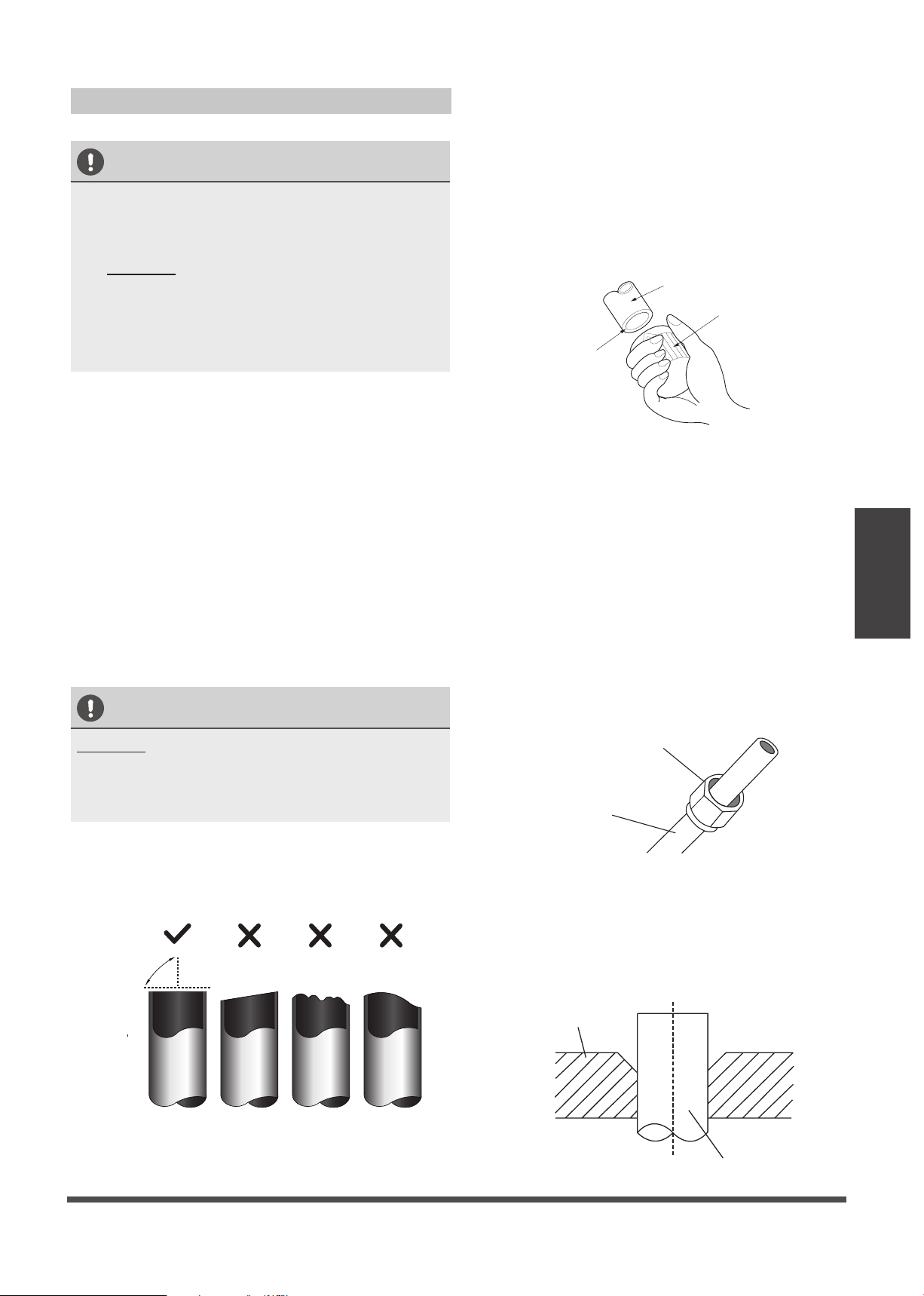
1.Make sure that the pipe is cut at a perfect 90°
angle. Refer to Fig. 7.1 for examples of bad cuts
Oblique
Rough
Warped
90°
Fig. 7.1
Step 2: Remove burrs.
Burrs can affect the air-tight seal of refrigerant
piping connection. They must be completely
removed.
1. Hold the pipe at a downward angle to
prevent burrs from falling into the pipe.
2. Using a reamer or deburring tool, remove
all burrs from the cut section of the pipe.
Pipe
Reamer
Point down
Fig. 7.2
Step 3: Flare pipe ends
Proper flaring is essential to achieve an airtight
seal.
1. After removing burrs from cut pipe, seal
the ends with PVC tape to prevent foreign
materials from entering the pipe.
2. Sheath the pipe with insulating material.
3. Place flare nuts on both ends of pipe.
Make sure they are facing in the right
direction, because you can’t put them on
or change their direction after flaring. See
Fig. 7.3
Flare nut
Copper pipe
Fig. 7.3
4. Remove PVC tape from ends of pipe when
ready to perform flaring work.
5. Clamp flare form on the end of the pipe.
The end of the pipe must extend beyond
the flare form.
Flare form
Pipe
Fig. 7.4
Page 18
Refrigerant Piping
Connection
6. Place flaring tool onto the form.
7. Turn the handle of the flaring tool
clockwise until the pipe is fully flared. Flare
the pipe in accordance with the dimensions
shown in table 7.2.
Table 7.2: PIPING EXTENSION BEYOND FLARE
FORM
Pipe
gauge
Tightening
torque
Flare dimension (A)
(Unit: in/mm)
Flare shape
Min. Max.
Ø 1/4”
14.2-17.2 N.m
(144-176 kgf.cm)
0.3/8.3 0.3/8.3
R0.4~0.8
45
°
±
2
90
°
±
4
A
Fig. 7.5
Ø 3/8”
32.7-39.9 N.m
(333-407 kgf.cm)
0.48/12.4 0.48/12.4
Ø 1/2”
49.5-60.3 N.m
(504-616 kgf.cm)
0.6/15.4 15.8/0.62
Ø 5/8”
61.8-75.4 N.m
(630-770 kgf.cm)
0.7/18.6 0.74/19
Ø 3/4”
97.2-118.6 N.m
(990-1210 kgf.cm)
0.9/22.9 0.91/23.3
8. Remove the flaring tool and flare form,
then inspect the end of the pipe for cracks
and even flaring.
Step 4: Connect pipes
Connect the copper pipes to the indoor unit first,
then connect it to the outdoor unit. You should
first connect the low-pressure pipe, then the high-
pressure pipe.
1. When connecting the flare nuts, apply a
thin coat of refrigeration oil to the flared
ends of the pipes.
2. Align the center of the two pipes that you
will connect.
Indoor unit tubing
Flare nut
Pipe
Fig. 7.6
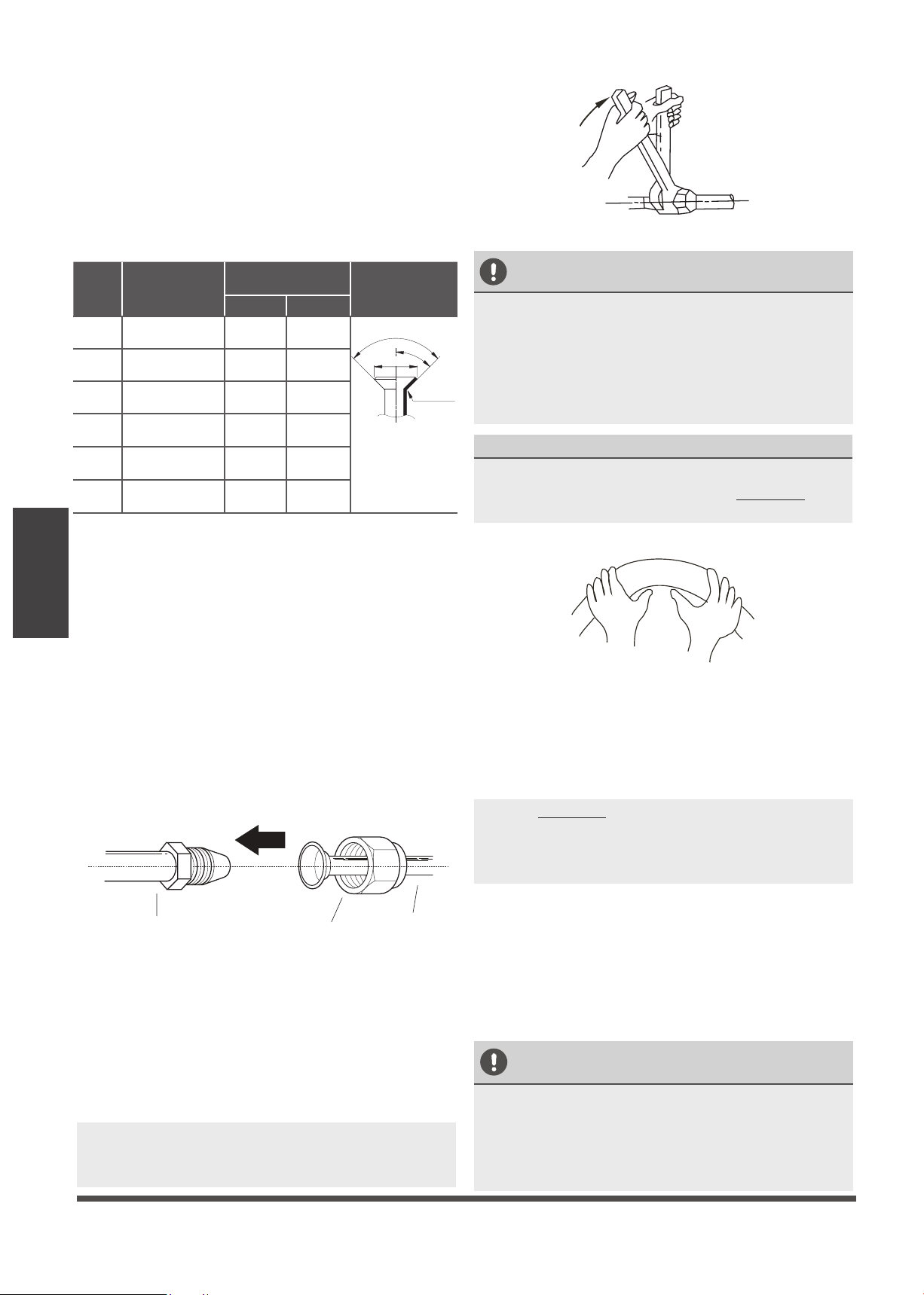
3. Tighten the flare nut as tightly as possible
by hand.
4. Using a spanner, grip the nut on the unit
tubing.
5. While firmly gripping the nut, use a torque
wrench to tighten the flare nut according
to the torque values in table 7.2.
NOTE: Use both a spanner and a torque wrench
when connecting or disconnecting pipes to/from
the unit.
Fig. 7.7
CAUTION
• Ensure to wrap insulation around the piping.
Direct contact with the bare piping may result
in burns or frostbite.
• Make sure the pipe is properly connected.
Over tightening may damage the bell mouth
and under tightening may lead to leakage.
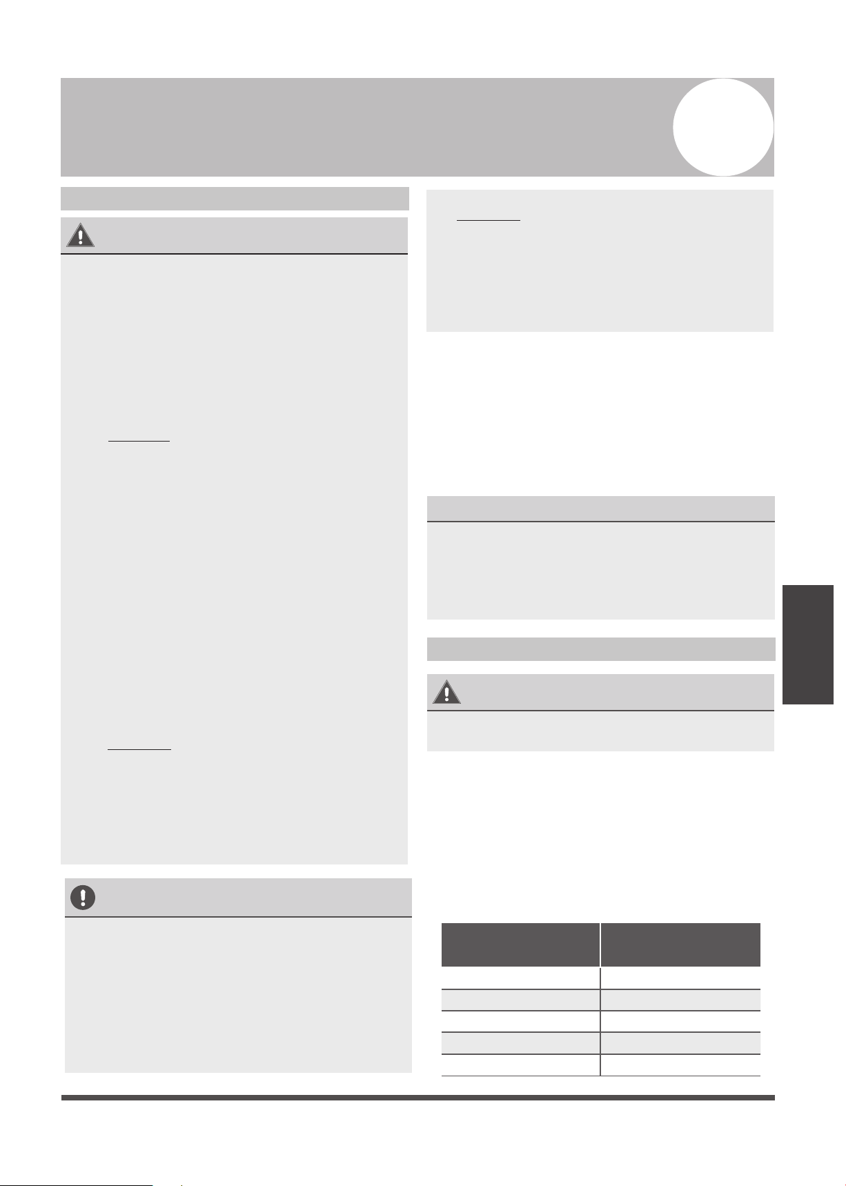
NOTE ON MINIMUM BEND RADIUS
Carefully bend the tubing in the middle
according to the diagram below. DO NOT bend
the tubing more than 90° or more than 3 times.
Bend the pipe with thumb
min- radiu s
(10cm) 3.9”
Fig. 7.8
6. After connecting the copper pipes to the
indoor unit, wrap the power cable, signal
cable and the piping together with
binding tape.
NOTE: DO NOT intertwine signal cable with
other wires. While bundling these items
together, do not intertwine or cross the signal
cable with any other wiring.
7. Thread this pipeline through the wall and
connect it to the outdoor unit.
8. Insulate all the piping, including the valves
of the outdoor unit.
9. Open the stop valves of the outdoor unit
to start the flow of the refrigerant between
the indoor and outdoor unit.
CAUTION
Check to make sure there is no refrigerant leak
after completing the installation work. If there is
a refrigerant leak, ventilate the area immediately
and evacuate the system (refer to the Air
Evacuation section of this manual).
Ø 7/8”
109.5-133.7 N.m
(1117-1364 kgf.cm)
1.06/27 1.07/27.3
Page 19
Wiring
TAKE NOTE OF FUSE SPECIFICATIONS
The air conditioner’s printed circuit board (PCB)
is designed with a fuse that provides overcurrent
protection. The specifications of the fuse are
printed on the circuit board, examples of such
are T5A/250VAC and T10A/250VAC.
Wiring
Safety P recautions
WARNING
• Disconnect the power supply before
working on the unit.
• All wiring must be performed according
to local and national regulations.
• Wiring must be done by a qualified
technician. Improper connections may
cause electrical malfunction, injury, or fire.
• An independent circuit and single outlet
must be used for this unit.
DO NOT plug another appliance or
charger into the same outlet. If the outlet
cannot handle the load or there is a defect
in the wiring, it can lead to shock, fire, and
unit and property damage.
• Connect the power cable to the terminals
and fasten it with a clamp. An insecure
connection may cause fire.
• Make sure that all wiring is done correctly
and the control board cover is properly
installed. Failure to do so can cause
overheating at the connection points, fire,
and electrical shock.
• Ensure that main power supply connection
is made through a switch that disconnects
all poles, with contact gap of at least 3mm
(0.118”).
If the supply cord is damaged, it must be
replaced by the manufacturer, its service
agent or similarly qualified persons in order
to avoid a hazard.
•
•
DO NOT modify the length of the power
cord or use an extension cord.
CAUTION
• Connect the out door wires before
connecting the indoor wires.
• Make sure you ground the unit. The
grounding wire should be located away
from gas pipes, water pipes, lightning rods,
telephone wires or other grounding wires.
Improper grounding may cause electrical
shock.
• DO NOT connect the unit to the power
source until all wiring and piping is
completed.
• Make sure that you do not cross your
electrical wiring with your signal wiring.
This may cause distortion and interference.
Follow these instructions to prevent distortion
when the compressor starts:
• The unit must be connected to the main
outlet. Normally, the power supply must
have a low output impedance of 32 ohms.
• No other equipment should be connected
to the same power circuit.
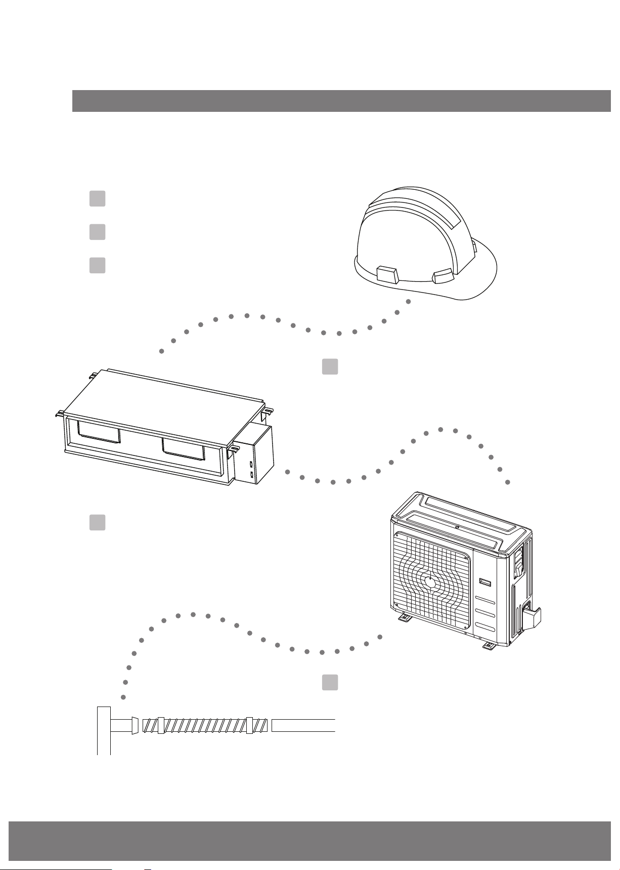
Outdoor Unit Wiring
WARNING
Before performing any electrical or wiring work,
turn off the main power to the system.
1. Prepare the cable for connection
a. You must first choose the right cable size
before preparing it for connection. Be sure
to use H07RN-F cables.
Table 8.1: Minimum Cross-Sectional Area
of Power and Signal Cables in North
America
Rated Cur rent of
Appliance (A)
AWG
≤ 7 18
7 - 13 16
13 - 18 14
18 - 25 12
25 - 30 10
8
Page 22
Wiring
b. Using wire strippers, strip the rubber jacket
from both ends of the signal cable to reveal
approximately 15cm (5.9”) of wire.
c.
Strip the insulation from the ends.
d. Using a wire crimper, crimp u-lugs on the
ends.
NOTE: When connecting the wires, strictly
follow the wiring diagram found inside the
electrical box cover.
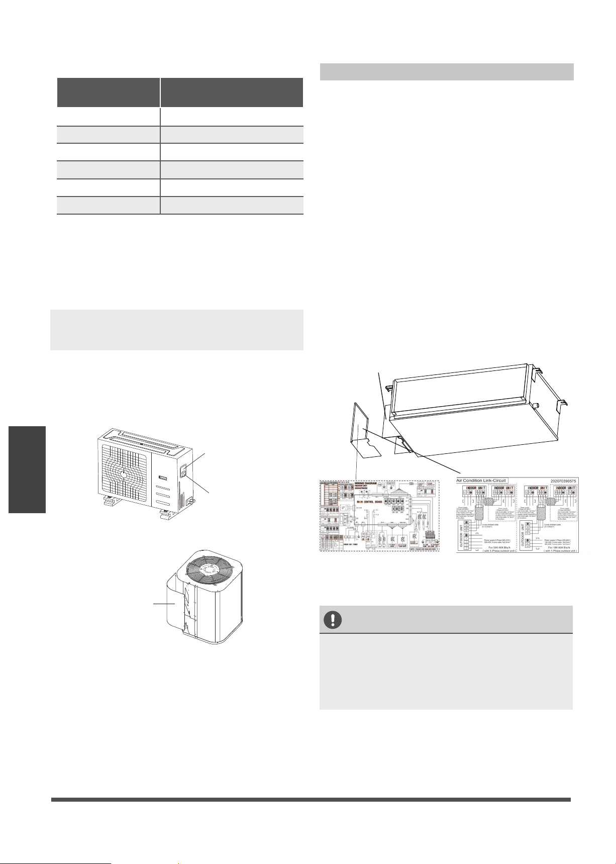
2. Remove the electric cover of the outdoor unit.
If there is no cover on the outdoor unit, take
off the bolts from the maintenance board and
remove the protection board.
(See Fig. 8.1, 8.2)
Cover
Screw
Fig. 8.1
Protection Board
Fig. 8.2
3. Connect the u-lugs to the terminals
Match the wire colors/labels with the labels on
the terminal block, and firmly screw the u-lug
of each wire to its corresponding terminal.
4. Clamp down the cable with the cable clamp.
5. Insulate unused wires with electrical tape. Keep
them away from any electrical or metal parts.
6. Reinstall the cover of the electric control box.
Indoor Unit Wiring
1. Prepare the cable for connection
a. Using wire strippers, strip the rubber jacket
from both ends of the signal cable to reveal
about 15cm (5.9”) of the wire.
b. Strip the insulation from the ends of the
wires.
c. Using a wire crimper, crimp the u-lugs to
the ends of the wires.
2. Remove the cover of the electric control box
on your indoor unit.
3. Connect the u-lugs to the terminals.
Match the wire colors/labels with the labels
on the terminal block, and firmly screw the
u-lug of each wire to its corresponding
terminal. Refer to the Serial Number and
Wiring Diagram located on the cover of the
electric control box.
Connective wiring diagram
Wiring diagram
Control box
CAUTION
• While connecting the wires, please strictly
follow the wiring diagram.
• The refrigerant circuit can become very
hot. Keep the interconnection cable away
from the copper tube.
4. Clamp down the cable with the cable clamp.
The cable must not be loose or pull on the
u-lugs.
5. Reattach the electric box cover.
Fig. 8.3
Table 8.2: Other World Regions
Rated Current of
Appliance (A)
Area (mm²)
Nominal Cross-Sectional
≤ 6 0.75
6 - 10 1
10 - 16 1.5
16 - 25 2.5
25- 32 4
32 - 45 6
Page 23
Wiring
Using the wire control to set external
static pressure (some models)
You can use the unit’s automatic airflow
adjustment function to set external static
pressure.
Automatic airflow adjustment is the volume
of blow-off air that has been automatically
adjusted to the quantity rated.
1. Make sure the test run is done with a dry
coil. If the coil is not dry, run the unit for 2
hours in FAN ONLY mode to dry the coil.
2. Check that both power supply wiring and
duct installation have been completed
Check that any closing dampers are open.
Check that the air filter is properly attached
to the air suction side passage of the unit.
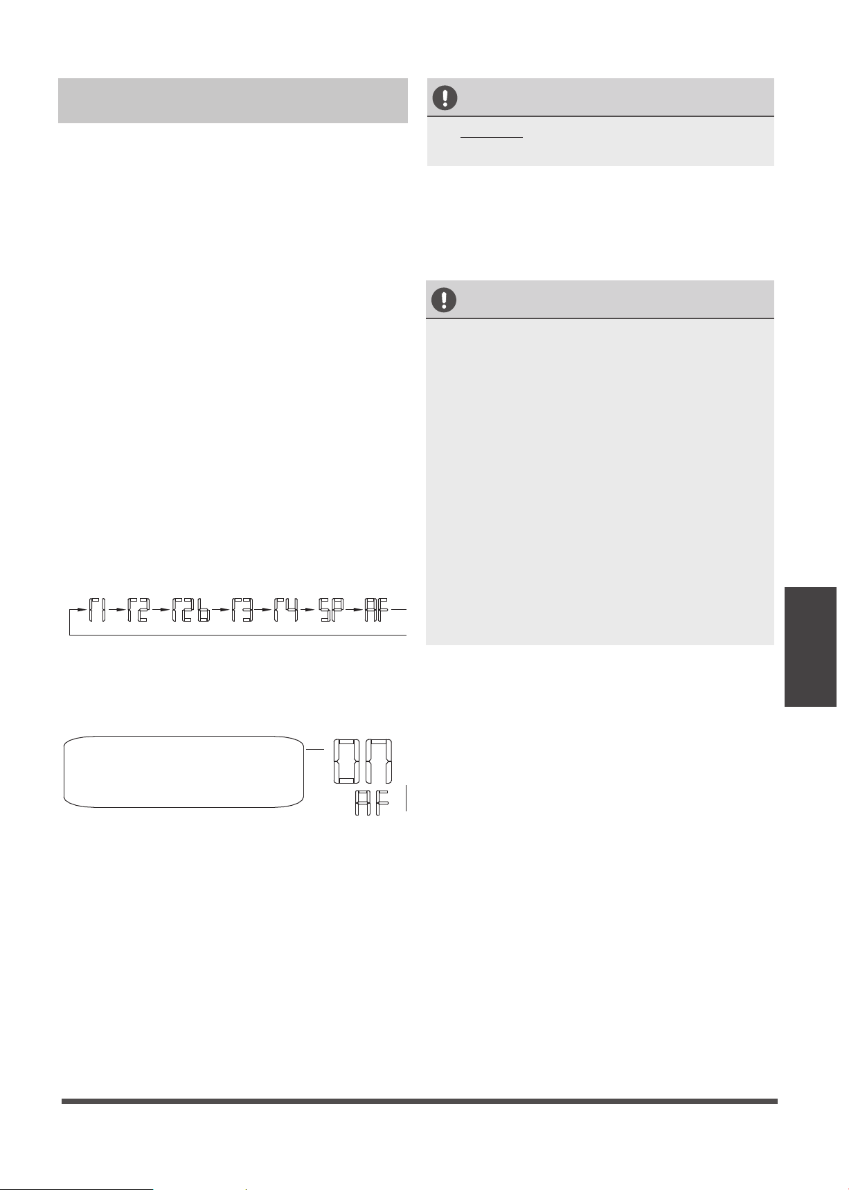
3. Set the parameters for automatic airflow
adjustment. When the air conditioning unit
is off, perform the follwoing steps:
- Press the button “COPY” long.
- Press “+” or “-” to select the AF.
- Press “CONFIRM”. The air conditioning
unit will then start the fan for airflow
automatic adjustment.
ON will flash during when the
fan is on during automatic
airflow adjustment.
After 3 to 6 minutes, the air conditioning
unit stops operating once automatic airflow
adjustment has finished.
•
•
CAUTION
• DO NOT adjust the dampers when
automatic airflow adjustment is active.
CAUTION
• If there is no change after airflow
adjustment in the ventilation paths, be sure
to reset automatic airflow adjustment.
• If there is no change to ventilation paths
after airflow adjustment,contact your dealer,
especially if this occurs after testing the
outdoor unit or if the unit has been moved
to a different location.
• Do not use automatic airflow adjustment
with remote control,if you are using booster
fans, outdoor air processing unit, or a HRV
via duct.
• If the ventilation paths have been changed,
reset airflow automatic adjustment as
described from step 3 onwards.
Page 22
Wiring
Power Specifications
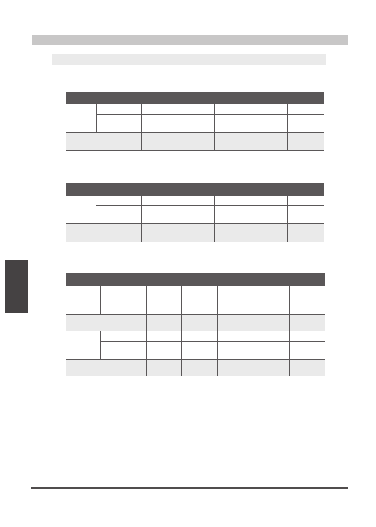
Indoor Power Supply Specifications
MODEL
(Btu/h)
≤18K 19K~24K 25K~36K 37K~48K 49K~60K
POWER
PHASE 1 Phase 1 Phase 1 Phase 1 Phase 1 Phase
FREQUENCY
AND VOLT
208-240V 208-240V 208-240V 208-240V 208-240V
CIRCUIT BREAKER/
FUSE(A)
25/20 32/25 50/40 70/55 70/60
MODEL
(Btu/h)
≤18K 19K~24K 25K~36K 37K~48K 49K~60K
POWER
PHASE 1 Phase 1 Phase 1 Phase 1 Phase 1 Phase
FREQUENCY
AND VOLT
208-240V 208-240V 208-240V 208-240V 208-240V
CIRCUIT BREAKER/
FUSE(A)
25/20 32/25 50/40 70/55 70/60
Outdoor Power Supply Specifications
Independent Power Supply Specifications
MODEL
(Btu/h)
≤18K 19K~24K 25K~36K 37K~48K 49K~60K
POWER
(indoor)
PHASE 1 Phase 1 Phase 1 Phase 1 Phase 1 Phase
FREQUENCY
AND VOLT
208-240V 208-240V 208-240V208-240V 208-240V
CIRCUIT BREAKER/
FUSE(A)
15/10 15/10 15/10 15/10 15/10
POWER
(outdoor)
PHASE 1 Phase 1 Phase 1 Phase 1 Phase 1 Phase
FREQUENCY
AND VOLT
208-240V 208-240V 208-240V
208-240V
208-240V
CIRCUIT BREAKER/
FUSE(A)
25/20 32/25 50/40 70/55 70/60
NOTE: Electric auxiliary heating type circuit breaker/fuse need to add more than 10 A.
Page 23
Air
Wiring
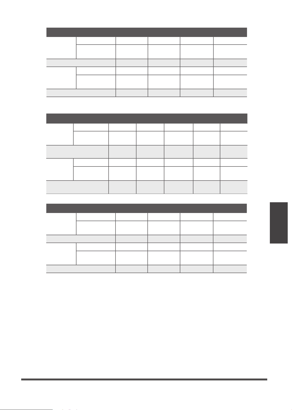
MODEL
(Btu/h)
≤18K 19K~24K 25K~36K 37K~48K 49K~60K
POWER
(indoor)
PHASE 1 Phase 1 Phase 1 Phase 1 Phase 1 Phase
FREQUENCY
AND VOLT
220-240V 220-240V 220-240V220-240V 220-240V
CIRCUIT BREAKER/
FUSE(A)
15/10 15/10 15/10 15/10 15/10
POWER
(outdoor)
PHASE 1 Phase 1 Phase 1 Phase 1 Phase 1 Phase
FREQUENCY
AND VOLT
208-240V 208-240V 208-240V
208-240V
208-240V
CIRCUIT BREAKER/
FUSE(A)
25/20 25/20 40/30 50/40 50/40
MODEL
(Btu/h)
≤36K 37K~60K ≤36K 37K~60K
POWER
(indoor)
PHASE 1 Phase 1 Phase 1 Phase 1 Phase
FREQUENCY
AND VOLT
208-240V 208-240V 208-240V 208-240V
CIRCUIT BREAKER/FUSE(A) 15/10 15/10 15/10 15/10
POWER
(outdoor)
PHASE 3 Phase 3 Phase 3 Phase 3 Phase
FREQUENCY
AND VOLT
380-420V 380-420V 208-240V 208-240V
CIRCUIT BREAKER/FUSE(A) 25/20 32/25 32/25 45/35
MODEL
(Btu/h)
≤36K 37K~60K ≤36K 37K~60K
POWER
(indoor)
PHASE 1 Phase 1 Phase 1 Phase 1 Phase
FREQUENCY
AND VOLT
220-240V 220-240V 220-240V 220-240V
CIRCUIT BREAKER/FUSE(A) 15/10 15/10 15/10 15/10
POWER
(outdoor)
PHASE 3 Phase 3 Phase 3 Phase 3 Phase
FREQUENCY
AND VOLT
380-420V 380-420V 208-240V 208-240V
CIRCUIT BREAKER/FUSE(A) 25/20 32/25 32/25 40/30
Inverter Type A/C Power Specifications
Page 24
Air Evacuation
Air Evacuation
Safety P recautions
CAUTION
• Use a vacuum pump with a gauge reading
lower than -0.1MPa and an air discharge capacity
above 40L/min.
• The outdoor unit does not need vacuuming.
DO NOT open the outdoor unit’s gas and
liquid stop valves.
• Ensure that the Compound Meter reads
-0.1MPa or below after 2 hours. If after
three hours the gauge reading is still above
-0.1MPa, check if there is a gas leak or
water inside the pipe. If there is no leak,
perform another evacuation for 1 or 2 hours.
• DO NOT use refrigerant gas to evacuate the
system.
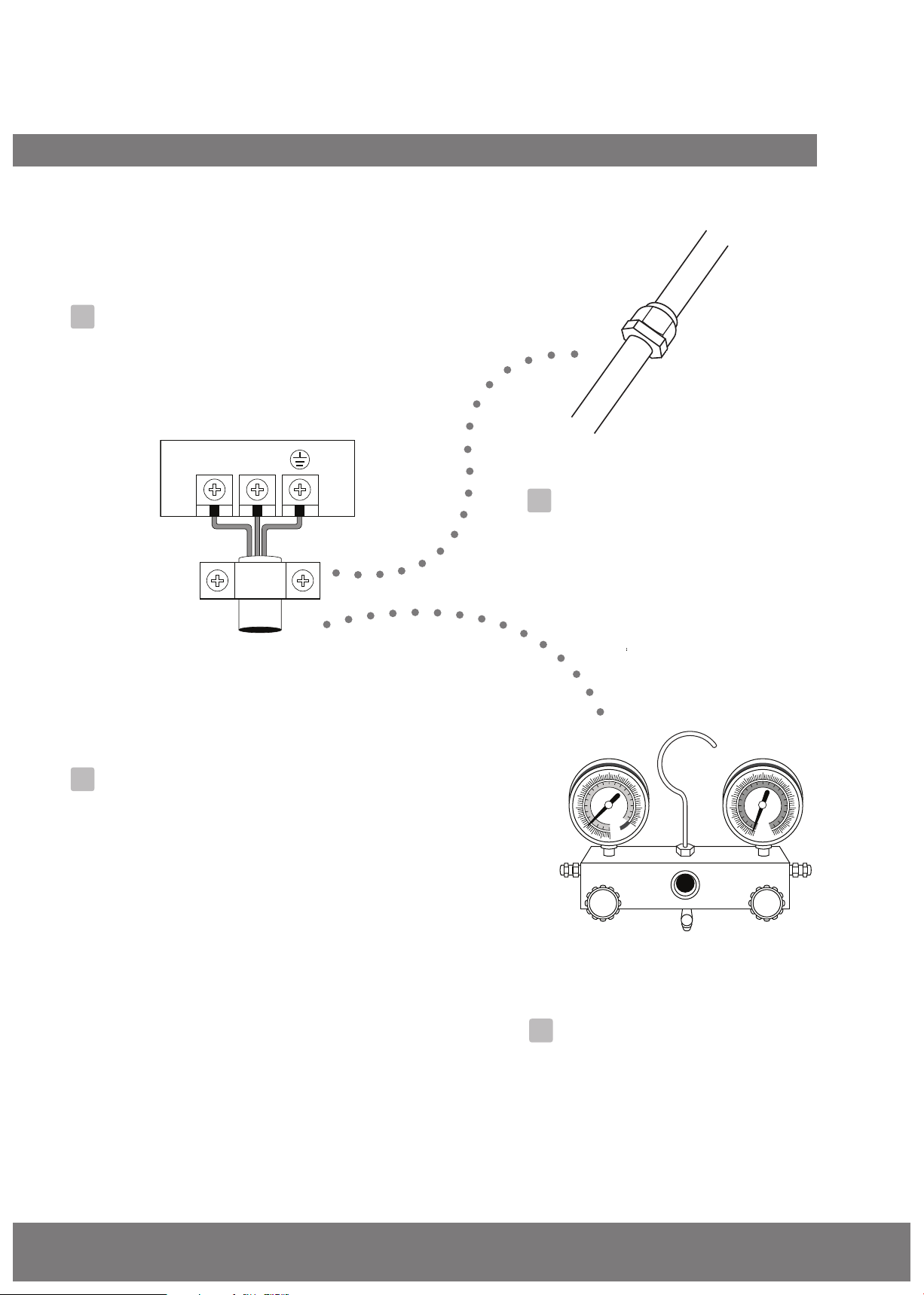
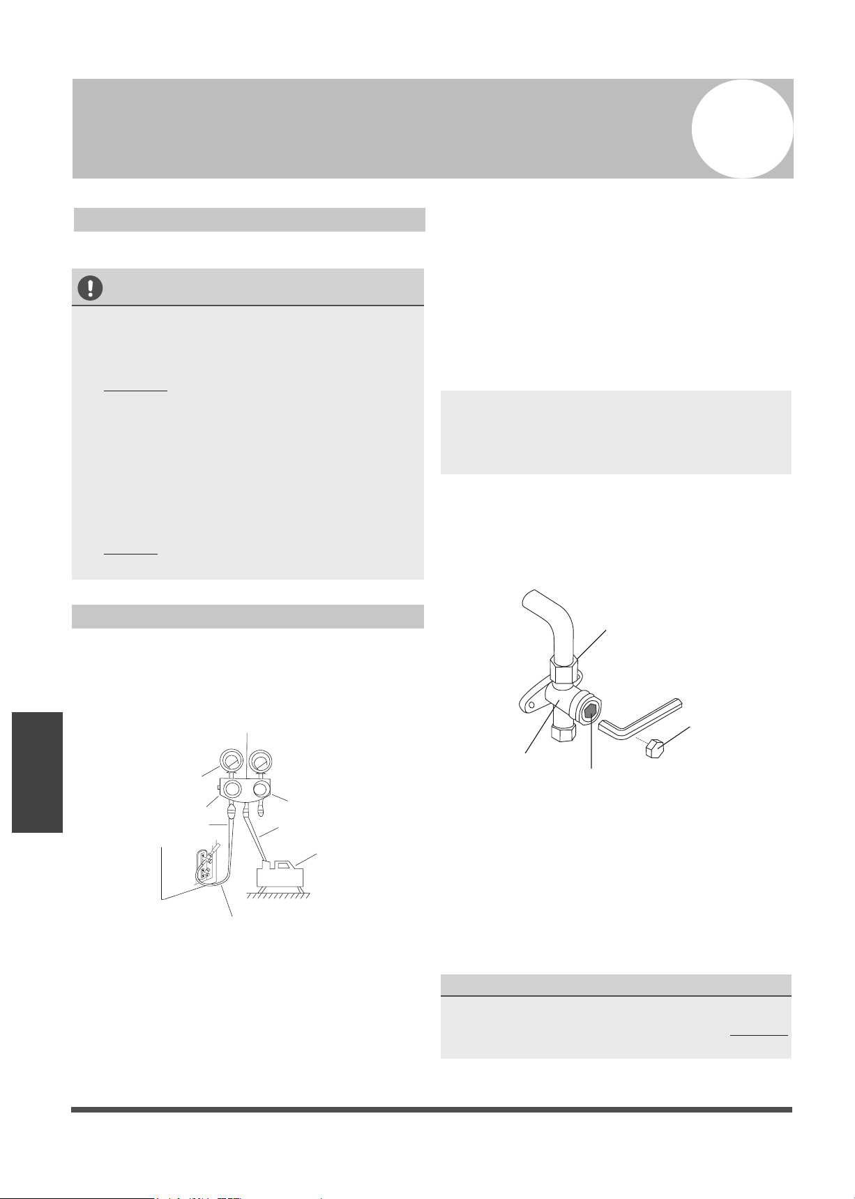
Evacuation Instructions
Before using a manifold gauge and a vacuum
pump, read their operation manuals to make
sure you know how to use them properly.
Manifold Gauge
Compound gauge
-76cmHg
Low pressure valve
High pressure valve
Charge hose
Charge hose
Vacuum pump
Pressure gauge
Low pressure valve
Fig. 9.1
1. Connect the manifold gauge’s charge hose
to the service port on the outdoor unit’s low
pressure valve.
2. Connect the manifold gauge’s charge hose
from the to the vacuum pump.
3. Open the Low Pressure side of the manifold
gauge.Keep the High Pressure side closed.
4. Turn on the vacuum pump to evacuate the
system.
5. Run the vacuum for at least 15 minutes, or
until the Compound Meter reads -76cmHG
(-1x10⁵Pa).
6. Close the manifold gauge’s Low Pressure
valve and turn off the vacuum pump.
7. Wait for 5 minutes, then check that there has
been no change in system pressure.
NOTE: If there is no change in system pressure,
unscrew the cap from the packed valve (high
pressure valve). If there is a change in system
pressure, there may be a gas leak.
8. Insert hexagonal wrench into the packed valve
(high pressure valve) and open the valve by
turning the wrench 1/4 counterclockwise.
Listen for gas to exit the system, then close the
valve after 5 seconds.
Flare nut
Cap
V
alve body
Valve stem
Fig. 9.2
9. Watch the Pressure Gauge for one minute to
make sure that there is no change in pressure. It
should read slightly higher than the atmospheric
pressure.
10.Remove the charge hose from the service port.
11.Using hexagonal wrench, fully open both the
high pressure and low pressure valves.
OPEN VALVE STEMS GENT LY
When opening valve stems, turn the hexagonal
wrench until it hits against the stopper. DO NOT
try to force the valve to open further.
12.Tighten valve caps by hand, then tighten it
using the proper tool.
9
Page 25
Air Evacuation
Note On Adding Refrigerant
CAUTION
• Refrigerant charging must be performed after wiring, vacuuming, and the leak testing.
• DO NOT exceed the maximum allowable quantity of refrigerant or overcharge the system.
Doing so can damage the unit or impact it’s functioning.
• Charging with unsuitable substances may cause explosions or accidents. Ensure that the
appropriate refrigerant is used.
• Refrigerant containers must be opened slowly. Always use protective gear when charging the
system.
• DO NOT mix refrigerants types.
Some systems require additional charging depending on pipe lengths. The standard pipe length
varies according to local regulations. For example, in North America, the standard pipe length is
7.5m (25’) In other areas, the standard pipe length is 5m (16‘). The additional refrigerant to be
charged can be calculated using the following formula:
Liquid Side Diameter
Ø1/4”(6.35) Ø3/8”(9.52) Ø1/2”(12.7)
R22
(orifice tube in the indoor unit):
(Total pipe length -
standard pipe length)x
0.32oZ(30g)/ft(m)
(Total pipe length -
standard pipe length)x
0.69oZ(65g)/ft(m)
(Total pipe length -
standard pipe length)x
1.23oZ(115g)/ft(m)
R22
(orifice tube in the outdoor unit):
(Total pipe length -
standard pipe length)
x0.16oZ(15g)/ft(m)
(Total pipe length -
standard pipe length)
x0.32oZ(30g)/ft(m)
(Total pipe length -
standard pipe length)
x0.64oZ(60g)/ft(m)
(Total pipe length -
standard pipe length)
0.69oZ(65g)/ft(m)
R410A:
(orifice tube in the indoor unit):
(Total pipe length -
standard pipe length)
x0.32oZ(30g)/ft(m)
(Total pipe length -
standard pipe length)
x0.69oZ(65g)/ft(m
(Total pipe length -
standard pipe length)
1.23oZ(115g)/ft(m)
R410A:
(orifice tube in the outdoor unit):
(Total pipe length -
standard pipe length)
x0.16oZ(15g)/ft(m)
(Total pipe length -
standard pipe length)
x0.32oZ(30g)/ft(m)
Page 26
Test Run
Befo re Test Run
A test run must be performed after the entire
system has been completely installed. Confirm
the following points before performing the test:
a) Indoor and outdoor units are properly
installed.
b) Piping and wiring are properly connected.
c) No obstacles near the inlet and outlet of
the unit that might cause poor performance
or product malfunction.
d) Refrigeration system does not leak.
e) Drainage system is unimpeded and
draining to a safe location.
f) Heating insulation is properly installed.
g) Grounding wires are properly connected.
h) Length of the piping and the added
refrigerant stow capacity have been
recorded.
i) Power voltage is the correct voltage for the
air conditioner.
CAUTION
Failure to perform the test run may result in unit
damage, property damage or personal injury.
Test Run Instructions
1. Open both the liquid and gas stop valves.
2. Turn on the main power switch and allow the
unit to warm up.
3. Set the air conditioner to COOL mode.
4. For the Indoor Unit
a. Ensure the remote control and its buttons
work properly.
b. Ensure the louvers move properly and can
be changed using the remote control.
c. Double check to see if the room
temperature is being registered correctly.
d. Ensure the indicators on the remote
control and the display panel on the indoor
unit work properly.
e. Ensure the manual buttons on the indoor
unit works properly.
f. Check to see that the drainage system is
unimpeded and draining smoothly.
g. Ensure there is no vibration or abnormal
noise during operation.
5. For the Outdoor Unit
a. Check to see if the refrigeration system is
leaking.
b. Make sure there is no vibration or
abnormal noise during operation.
c. Ensure the wind, noise, and water
generated by the unit do not disturb your
neighbors or pose a safety hazard.
6. Drainage Test
a. Ensure the drainpipe flows smoothly. New
buildings should perform this test before
finishing the ceiling.
b. Remove the test cover. Add 2,11quart of
water to the tank through the attached
tube.
c. Turn on the main power switch and run
the air conditioner in COOL mode.
d. Listen to the sound of the drain pump to
see if it makes any unusual noises.
e. Check to see that the water is discharged.
It may take up to one minute before the
unit begins to drain depending on the
drainpipe.
f. Make sure that there are no leaks in any of
the piping.
g. Stop the air conditioner. Turn off the main
power switch and reinstall the test cover.
NOTE: If the unit malfunctions or does not
operate according to your expectations, please
refer to the Troubleshooting section of the
Owner’s Manual before calling customer service.
Test Run
10