L ! T E
Range Hood
Use & Care / Installation Manual
Campana de cocina
Manual de uso y cuidado / instalaci6n
,,®
Models
Modelos
233.51303200 (30" wide - Stainless)
233.51363200 (36" wide - Stainless)
233.51423200 (42" wide - Stainless)
w-
Z_
O
HBO027
,_ INTENDED FOR DOMESTIC COOKING ONLY,_
_1, CONCEBIDO SOLO PARA USO DOMC:STICO ,_
V05526 rev.D Sears, Roebuck and Co., Hoffman Estates, IL 60179 U.S.A. www.sears.com
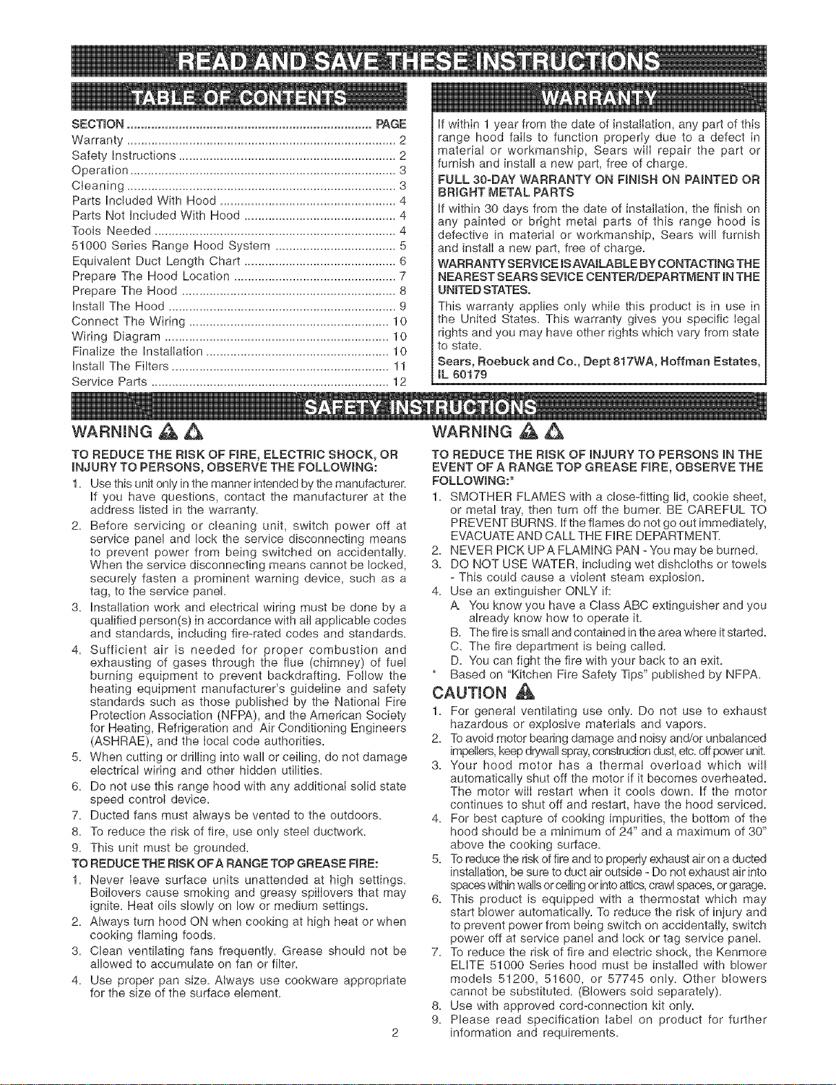
if within 1 year from the date of instaflation, any part of this
range hood fails to function properly due to a defect in
material or workmanship, Sears will repair the part or
furnish and install a new part, free of charge.
FULL 30-DAY WARRANTY ON FINISH ON PAINTED OR
BRIGHT METAL PARTS
if within 30 days from the date of installation, the finish on
any painted or bright metal parts of this range hood is
defective in material or workmanship, Sears will furnish
and install a new part, free of charge.
WARRANTY SERVICE iSAVAILABLE BYCONTACTING THE
NEAREST SEARS SEVtCE CENTER/DEPARTMENT INTHE
UNITED STATES.
This warranty applies only while this product is in use in
the United States. This warranty gives you specific legal
rights and you may have other rights which vary from state
to state.
Sears, Roebuck and Co., Dept 817WA, Boffman Estates,
tL 60179
WARNING A A
TO REDUCE THE RISK OF FIRE, ELECTRIC SHOCK, OR
INJURY TO PERSONS, OBSERVE THE FOLLOWING:
1. Use this unit only inthe manner intended by the manufacturer.
if you have questions, contact the manufacturer at the
address listed in the warranty.
2. Before servicing or cleaning unit, switch power off at
service panel and lock the service disconnecting means
to prevent power from being switched on accidentally.
When the service disconnecting means cannot be locked,
securely fasten a prominent warning device, such as a
tag, to the service panel.
3. InstaIlation work and electrical wiring must be done by a
qualified person(s) in accordance with all applicable codes
and standards, including fire-rated codes and standards.
4. Sufficient air is needed for proper combustion and
exhausting of gases through the flue (chimney) of fuel
burning equipment to prevent backdrafting. Follow the
heating equipment manufacturer's guideline and safety
standards such as those published by the National Fire
Protection Association (NFPA), and the American Society
for Heating, Refrigeration and Air Conditioning Engineers
(ASHRAE), and the local code authorities.
5. When cutting or drilling into wall or ceiling, do not damage
electrical wiring and other hidden utilities.
6. Do not use this range hood with any additional solid state
speed control device.
7. Ducted fans must always be vented to the outdoors.
8. To reduce the risk of fire, use only steel ductwork.
9. This unit must be grounded.
TO REDUCE THE RiSK OF A RANGE TOP GREASE FIRE:
1. Never leave surface units unattended at high settings.
Boilovers cause smoking and greasy spilIovers that may
ignite. Heat oils slowly on low or medium settings.
2. Always turn hood ON when cooking at high heat or when
cooking flaming foods.
3. Clean ventilating fans frequently. Grease should not be
allowed to accumulate on fan or filter.
4. Use proper pan size. Always use cookware appropriate
for the size of the surface element.
WARNING A A
TO REDUCE THE RiSK OF iNJURY TO PERSONS iN THE
EVENT OF A RANGE TOP GREASE FIRE, OBSERVE THE
FOLLOWING:*
1. SMOTHER FLAMES with a close-fitting lid, cookie sheet,
or metal tray, then turn off the burner. BE CAREFUL TO
PREVENT BURNS. if the flames do not go out immediately,
EVACUATE AND CALL THE FiRE DEPARTMENT.
2. NEVER PiCK UPA FLAMING PAN - You may be burned.
3. DO NOT USE WATER, including wet dishcloths or towels
- This could cause a violent steam explosion.
4. Use an extinguisher ONLY if:
A You know you have a Class ABC extinguisher and you
already know how to operate it.
B. The fire is small and contained inthe area where it started.
C. The fire department is being called.
D. You can fight the fire with your back to an exit.
* Based on "Kitchen Fire Safety Tips" published by NFPA.
CAUTION
1. For general ventilating use only. Do not use to exhaust
hazardous or explosive materials and vapors.
2. Toavoid motor bearing damage and noisy and/or unbalanced
impellers, keep drywallspray,constructiondust,etc.off power unit.
3. Your hood motor has a thermal overload which wiI!
automatically shut off the motor if it becomes overheated.
The motor will restart when it cools down. if the motor
continues to shut off and restart, have the hood serviced.
4. For best capture of cooking impurities, the bottom of the
hood should be a minimum of 24" and a maximum of 30"
above the cooking surface.
5. Toreduce the riskof fire and to properly exhaust air on a ducted
installation, be sure to duct air outside - Do not exhaust air into
spaceswithinwallsorceilingor intoattics,crawlspaces,or garage.
6. This product is equipped with a thermostat which may
start blower automatically. To reduce the risk of injury and
to prevent power from being switch on accidentally, switch
power off at service panel and lock or tag service panel.
7. To reduce the risk of fire and electric shock, the Kenmore
ELITE 51000 Series hood must be installed with blower
models 51200, 51600, or 57745 only. Other blowers
cannot be substituted. (Blowers sold separately).
8. Use with approved cord-connection kit only.
9. Please read specification label on product for further
information and requirements.
Always turn ON your hood before you begin cooking in order
to establish an air flow in the kitchen. Let the blower run for a
few minutes to clear the air after you turn off the range. This
will help keep the whole kitchen cleaner and brighter.
= 4-EB
O
I
3
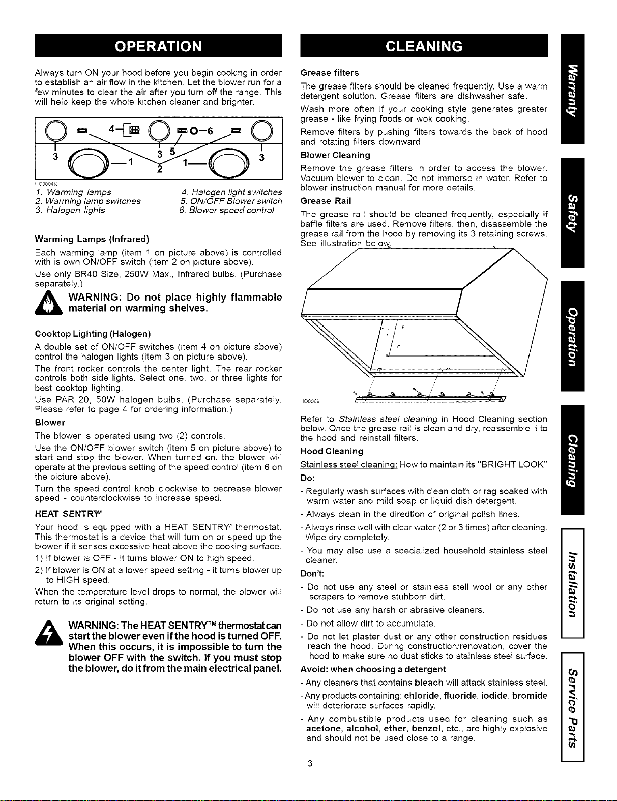
HCOO04K
1. Warming lamps
2. Warming lamp switches
3. Halogen lights
4. Halogen light switches
5. ON/OFF Blower switch
6. Blower speed control
Warming Lamps (Infrared)
Each warming lamp (item 1 on picture above) is controlled
with is own ON/OFF switch (item 2 on picture above).
Use only BR40 Size, 250W Max., Infrared bulbs. (Purchase
separately.)
_._ ARNING: Do not place highly flammable
material on warming shelves.
Cooktop Lighting (Halogen)
A double set of ON/OFF switches (item 4 on picture above)
control the halogen lights (item 3 on picture above).
The front rocker controls the center light. The rear rocker
controls both side lights. Select one, two, or three lights for
best cooktop lighting.
Use PAR 20, 50W halogen bulbs. (Purchase separately.
Please refer to page 4 for ordering information.)
Blower
The blower is operated using two (2) controls.
Use the ON/OFF blower switch (item 5 on picture above) to
start and stop the blower. When turned on, the blower will
operate at the previous setting of the speed control (item 6 on
the picture above).
Turn the speed control knob clockwise to decrease blower
speed - counterclockwise to increase speed.
HEAT SENTR_
Your hood is equipped with a HEAT SENTR_ thermostat.
This thermostat is a device that will turn on or speed up the
blower if it senses excessive heat above the cooking surface.
1) If blower is OFF - it turns blower ON to high speed.
2) If blower is ON at a lower speed setting - it turns blower up
to HIGH speed.
When the temperature level drops to normal, the blower will
return to its original setting.
,_ TM
WARNING: The HEAT SENTRY thermostatcan
start the blower even ifthe hood isturned OFF.
When this occurs, it is impossible to turn the
blower OFF with the switch. If you must stop
the blower, do itfrom the main electrical panel.
Grease filters
The grease filters should be cleaned frequently. Use a warm
detergent solution. Grease filters are dishwasher safe.
Wash more often if your cooking style generates greater
grease - like frying foods or wok cooking.
Remove filters by pushing filters towards the back of hood
and rotating filters downward.
Blower Cleaning
Remove the grease filters in order to access the blower.
Vacuum blower to clean. Do not immerse in water. Refer to
blower instruction manual for more details.
Grease Rail
The grease rail should be cleaned frequently, especially if
baffle filters are used. Remove filters, then, disassemble the
grease rail from the hood by removing its 3 retaining screws.
See illustration below.
o
/% _
/
,/
HD0069 / "_
Refer to Stainless steel cleaning in Hood Cleaning section
below. Once the grease rail is clean and dry, reassemble it to
the hood and reinstall filters.
Hood Cleaning
Stainless steel cleaninq: How to maintain its "BRIGHT LOOK"
Do:
- Regularly wash surfaces with clean cloth or rag soaked with
warm water and mild soap or liquid dish detergent.
- Always clean in the diredtion of original polish lines.
- Always rinse well with clear water (2 or 3 times) after cleaning.
Wipe dry completely.
- You may also use a specialized household stainless steel
cleaner.
Don't: _"
- Do not use any steel or stainless stell wool or any other
scrapers to remove stubborn dirt.
- Do not use any harsh or abrasive cleaners.
- Do not allow dirt to accumulate.
- Do not let plaster dust or any other construction residues --
reach the hood. During construction/renovation, cover the
hood to make sure no dust sticks to stainless steel surface. --
Avoid: when choosing a detergent
- Any cleaners that contains bleach will attack stainless steel.
-Any products containing: chloride, fluoride, iodide, bromide _,
will deteriorate surfaces rapidly.
- Any combustible products used for cleaning such as _1
acetone, alcohol, ether, benzol, etc., are highly explosive
and should not be used close to a range. _,
3 m
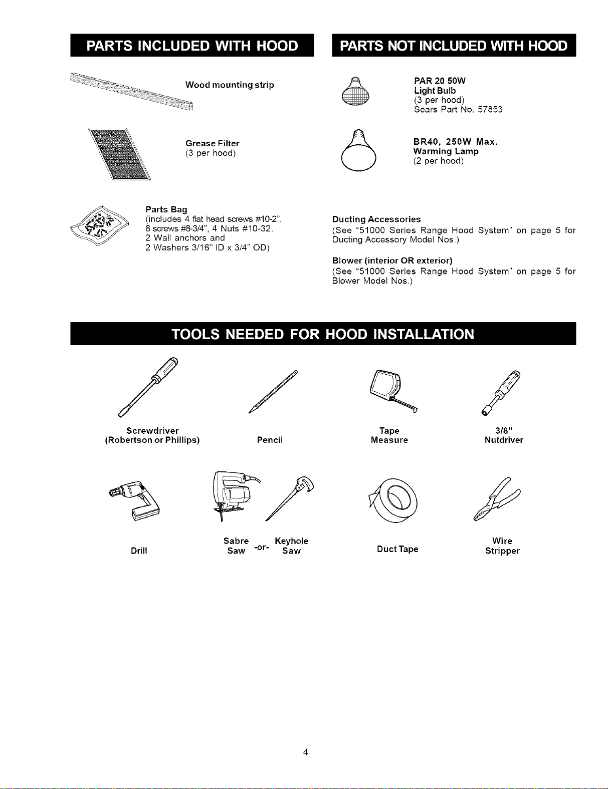
_ Wood
mounting strip
Grease Filter
(3 per hood)
PAR 20 50W
Light Bulb
(3 per hood)
Sears Part No. 57853
(_ BR40, 250W Max.
Warming Lamp
(2 per hood)
Parts Bag
(includes 4 fiat head screws #10-2",
8 screws #8-3/4", 4 Nuts #10-32,
2 Wall anchors and
2 Washers 3/16" ID x 3/4" OD)
Ducting Accessories
(See "51000 Series Range Hood System" on page 5 for
Ducting Accessory Model Nos.)
Blower (interior OR exterior)
(See "51000 Series Range Hood System" on page 5 for
Blower Model Nos.)
J /
Screwdriver
(Robertson or Phillips) Pencil
Q /
Tape 3/8"
Measure Nutdriver
Sabre
Drill Saw
Keyhole
-or- Saw Duct Tape
Wire
Stripper
F
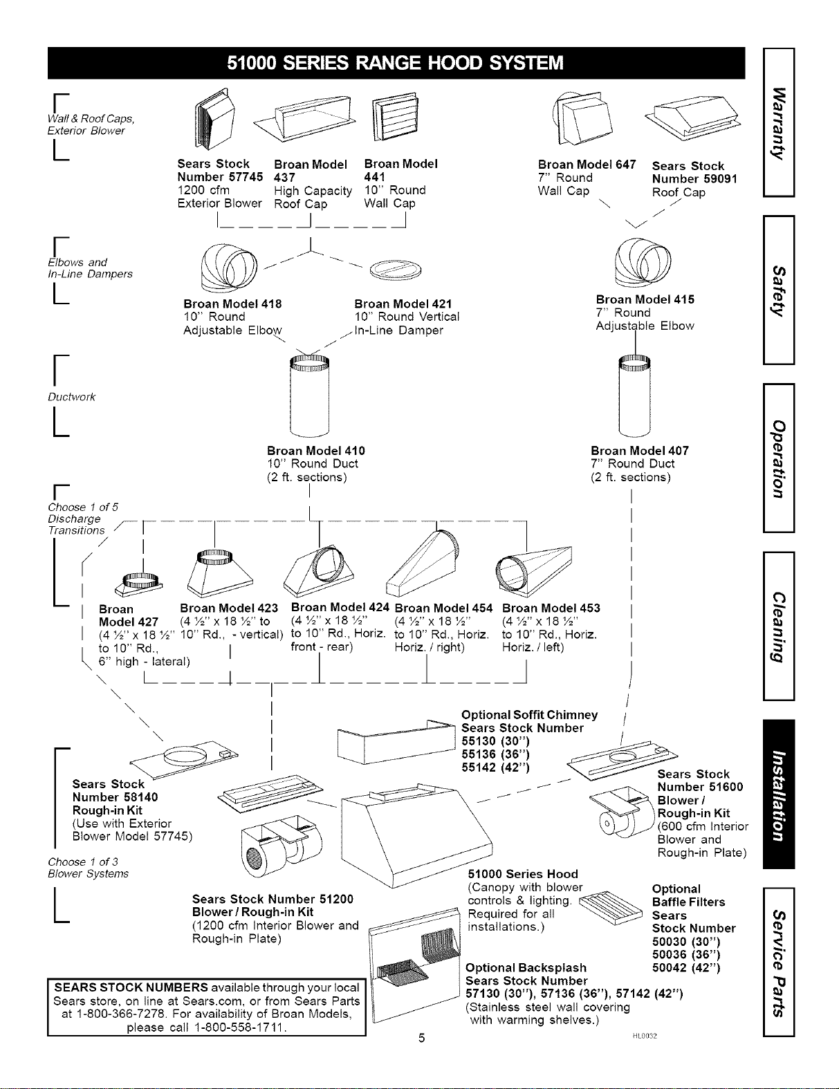
Wall & Roof Caps,
Exterior Blower
L
F
Elbows and
In-Line Dampers
L
F
Ductwork
L
F
Choose 1 of 5
Discharge _ 1
Transitions
(
I
I Broan
Model 427
I
i tol0"Rd.,
6" high - lateral)
\ L
\
\
\
Sears Stock Broan Model
Number 57745 437
1200 cfm High Capacity
Exterior Blower Roof Cap
I I
Broan Model 418
10" Round
Adjustable Elbow
/
Broan Model
441
10" Round
Wall Cap
I
--©
Broan Model 421
10" Round Vertical
/In-Line Damper
Broan Model 410
10" Round Duct
(2 ft. sections)
I
I
Broan Model 647
7" Round
Wall Cap
Sears Stock
Number 59091
Roof Cap
\ /
©
Broan Model 415
7" Round
Adjustable Elbow
Broan Model 407
7" Round Duct
(2 ft. sections)
Broan Model 423 Broan Model 424 Broan Model 454 Broan Model 453
(4 ½" x 18 ½" to (4 ½" x 18 ½" (4 ½" x 18 ½" (4 ½" x 18 ½"
(4½"x18½" 10"Rd., -vertical) tol0"Rd.,Horiz, tol0"Rd.,Horiz, tol0"Rd.,Horiz.
I front - rear) Horiz. / right) Horiz. / left)
\
mSears Sto_
i
i
i
i
Number 58140
Optional Soffit Chimney
_ Sears Stock Numbe_
55130 (30")
55136 (36")
55142 (42") rs Stock
__ f- -_ J _ Number 51600
// // _ _ Blower/
/ Rough-in Kit
_JJ_J (600 cfm Interior
"_ Blower and
Rough-in Kit
(Use with Exterior
Blower Model 57745)
Choose 1 of 3
Blower Systems
L
Sears Stock Number 51200
Blower / Rough-in Kit
(1200 cfm Interior Blower and
Rough-in Plate)
SEARS STOCK NUMBERS available through your local
Sears store, on line at Sears.com, or from Sears Parts
at 1-800-366-7278. For availability of Broan Models,
pease ca 1-800-558-1711.
Rough-in Plate)
51000 Series Hood
(Canopy with blower _ Optional
controls & lighting. _-._ Baffle Filters
Required for all _ Sears
installations.) Stock Number
50030 (30")
50036 (36")
Optional Backsplash 50042 (42")
Sears Stock Number
57130 (30"), 57136 (36"), 57142 (42")
(Stainless steel wall covering
with warming shelves.)
HL0032
i
i
o_
m
i
2
m
i
(b
O_
Cb
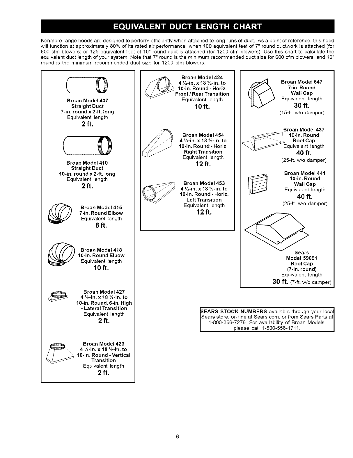
Kenmorerangehoodsaredesignedtoperformefficientlywhenattachedtolongrunsofduct.Asapointofreference,thishood
willfunctionatapproximately80%ofitsratedairperformancewhen100equivalentfeetof7"roundductworkisattached(for
600cfmblowers)or125equivalentfeetof10"roundductisattached(for1200cfmblowers).Usethischarttocalculatethe
equivalentductlengthofyoursystem.Notethat7"roundistheminimumrecommendedductsizefor600cfmblowers,and10"
roundistheminimumrecommendedductsizefor1200cfmblowers.
Broan Model 407
Straight Duct
7-in. round x 2-ft. long
Equivalent length
2ft.
Broan Model 410
Straight Duct
10-in. round x 2-ft. long
Equivalent length
2ft.
Broan Model 415
7-in. Round Elbow
Equivalent length
8ft.
Broan Model 418
10-in. Round Elbow
Equivalent length
10ft.
Broan Model 427
4 4/2-in. x 18 'A-in. to
10-in. Round, 6-in. High
- Lateral Transition
Equivalent length
2ft.
Broan Model 423
41A-in. x 181A-in. to
10-in. Round - Vertical
Transition
Equivalent length
2ft.
Broan Model 424
4 V2-in. x 18 1A-in. to
10-in. Round - Horiz.
Front / Rear Transition
Equivalent length
10ft.
Broan Model 454
4 V2-in. x 18 1A-in. to
10-in. Round - Horiz.
Right Transition
Equivalent length
12ft.
Broan Model 453
41A-in. x 18 Y2-in. to
10-in. Round - Horiz.
Left Transition
Equivalent length
12ft.
Broan Model 647
7-in. Round
Wall Cap
Equivalent length
30 ft.
(15-ft. w/o damper)
Broan Model 437
10-in. Round
Roof Cap
_uivalent length
40 ft.
(25-ft. wio damper)
Broan Model 441
10-in. Round
Wall Cap
Equivalent length
40 ft.
(25-ft. w/o damper)
Sears
Model 59091
Roof Cap
(7-in. round)
Equivalent length
30 ft, (7-ft. w/o damper)
EARS STOCK NUMBERS available through your Ioca_
ears store, on line at Sears.com, or from Sears Parts atI
1-800-366-7278. For availability of Broan Models, I
please call 1-800-558-1711. I
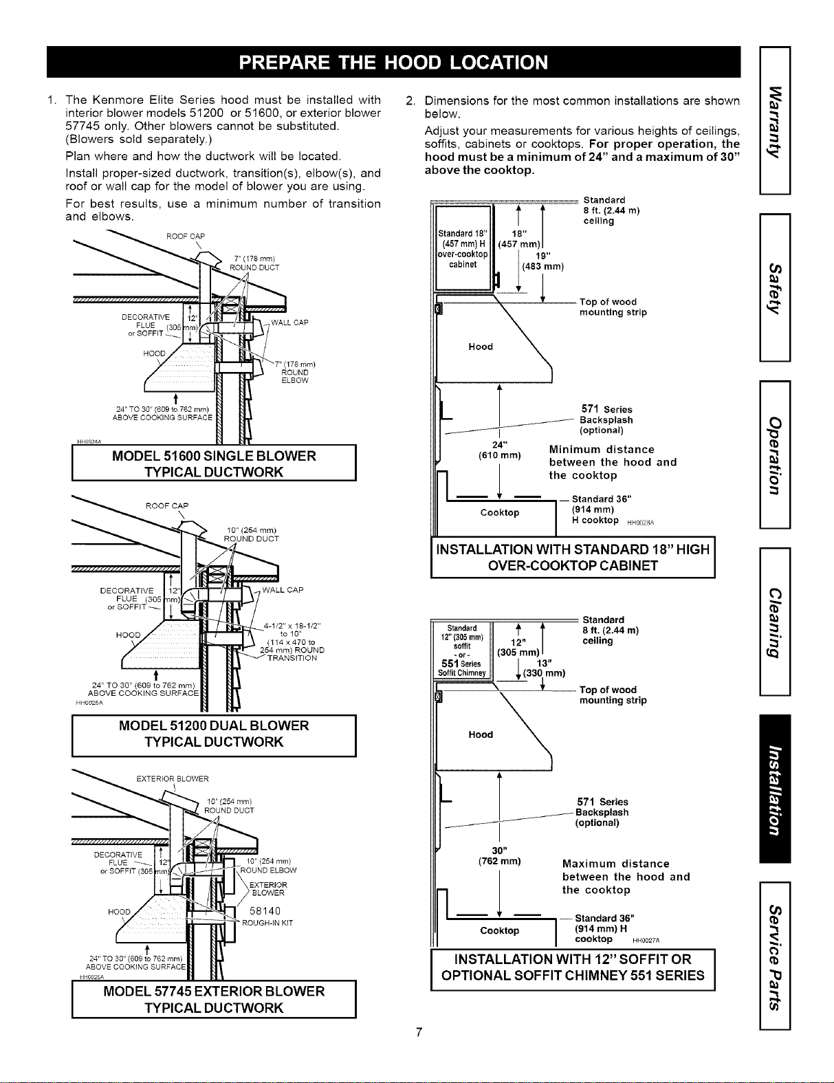
1. The Kenmore Elite Series hood must be installed with
interior blower models 51200 or 51600, or exterior blower
57745 only. Other blowers cannot be substituted.
(Blowers sold separately.)
Plan where and how the ductwork will be located.
Install proper-sized ductwork, transition(s), elbow(s), and
roof or wall cap for the model of blower you are using.
For best results, use a minimum number of transition
and elbows.
ROOF CAP
7" (I78 ram)
ROUND DUCT
HH0_24A
I
DECORATIVE
FLUE (305
or SOFFIT _
HOOD
t
24" TO 30" (609 to 782 mm)
ABOVE COOKING SURFACE
WALL CAP
ROUND
ELBOW
MODEL 51600 SINGLE BLOWER I
I
TYPICAL DUCTWORK
ROOF CAP
\
10" (254 ram)
ROUND DUCT
DECORATIVE
FLUE (305
or SOFFIT
HOOD
t
24" TO 30" (606 to 762 i'qrn)
ABOVE COOKING SURFACE
WALL CAP
4-1/2" x 18-1/2"
to 10"
(114 x470to
ROUND
MODEL 51200 DUAL BLOWER |
]
TYPICAL DUCTWORK
EXTERIOR BLOWER
10"(254mm)
ROUNDDUCT
DECORATIVE
FLUE 10" (254 ram)
or SOFFIT (305
EXTERIOR
) BLOWER
HOOD 58140
ROUGH-IN KIT
t
24" TO 30" (609 to 762 mm)
ABOVE COOKING SURFACE
MODEL 57745 EXTERIOR BLOWER /
J
TYPICAL DUCTWORK
Dimensions for the most common installations are shown
below.
Adjust your measurements for various heights of ceilings,
soffits, cabinets or cooktops. For proper operation, the
hood must be a minimum of 24" and a maximum of 30"
above the cooktop.
Standard
8 ft. (2.44 m)
ceiling
19"
(483 mm)
H°°d X
24"
(610 ram)
Top of wood
mounting strip
571 Series
Backsplash
(optional)
Minimum distance
between the hood and
the cooktop
_l_
-- Standard 36"
(914 mm)
Cooktop H cooktop HHOO28A
INSTALLATION WITH STANDARD 18" HIGH
OVER-COOKTOP CABINET
Standard
Standard 8 ft. (2,44 m)
12"(305ram) ceiling
soffit
13"
(33mm)O Top ofwood
X mounting strip
Hood
-- l 571 Series
I _ Backsplash
optional)
30"
(762 mm) Maximum distance
between the hood and
the cooktop
_ -- Standard 36"
Cooktop (914 mm) H
cooktop HHOO27A
INSTALLATION WITH 12" SOFFIT OR
OPTIONAL SOFFIT CHIMNEY 551 SERIES
m
m
O_
m
m
O
=
m
m
C3
(b
1.
4.
O_ Oo O_
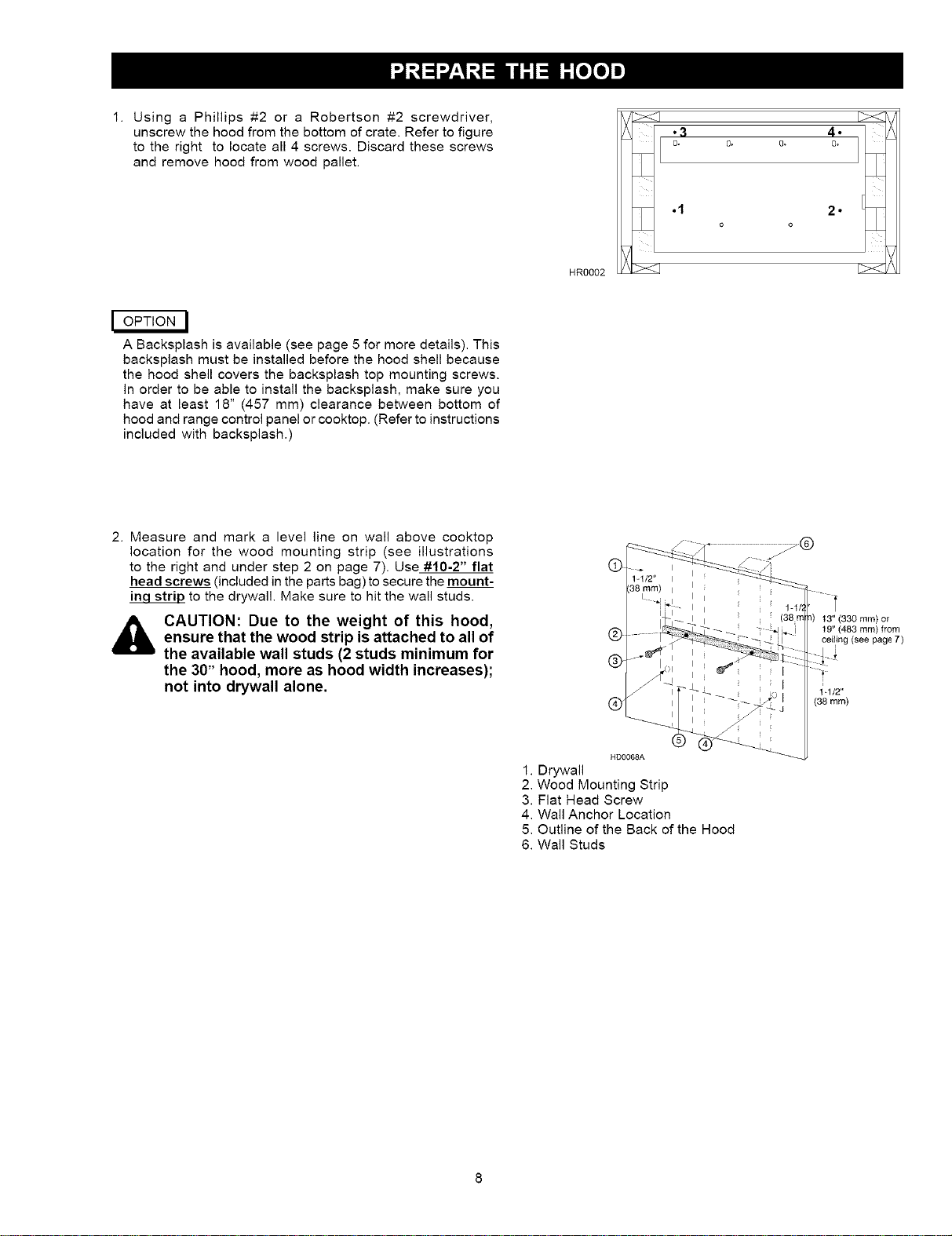
Using a Phillips #2 or a Robertson #2 screwdriver,
unscrew the hood from the bottom of crate. Refer to figure
to the right to locate all 4 screws. Discard these screws
and remove hood from wood pallet.
0,
.1
HR0002
2 •
o o
I OPTION I
A Backsplash is available (see page 5 for more details). This
backsplash must be installed before the hood shell because
the hood shell covers the backsplash top mounting screws.
In order to be able to install the backsplash, make sure you
have at least 18" (457 mm) clearance between bottom of
hood and range control panel or cooktop. (Refer to instructions
included with backsplash.)
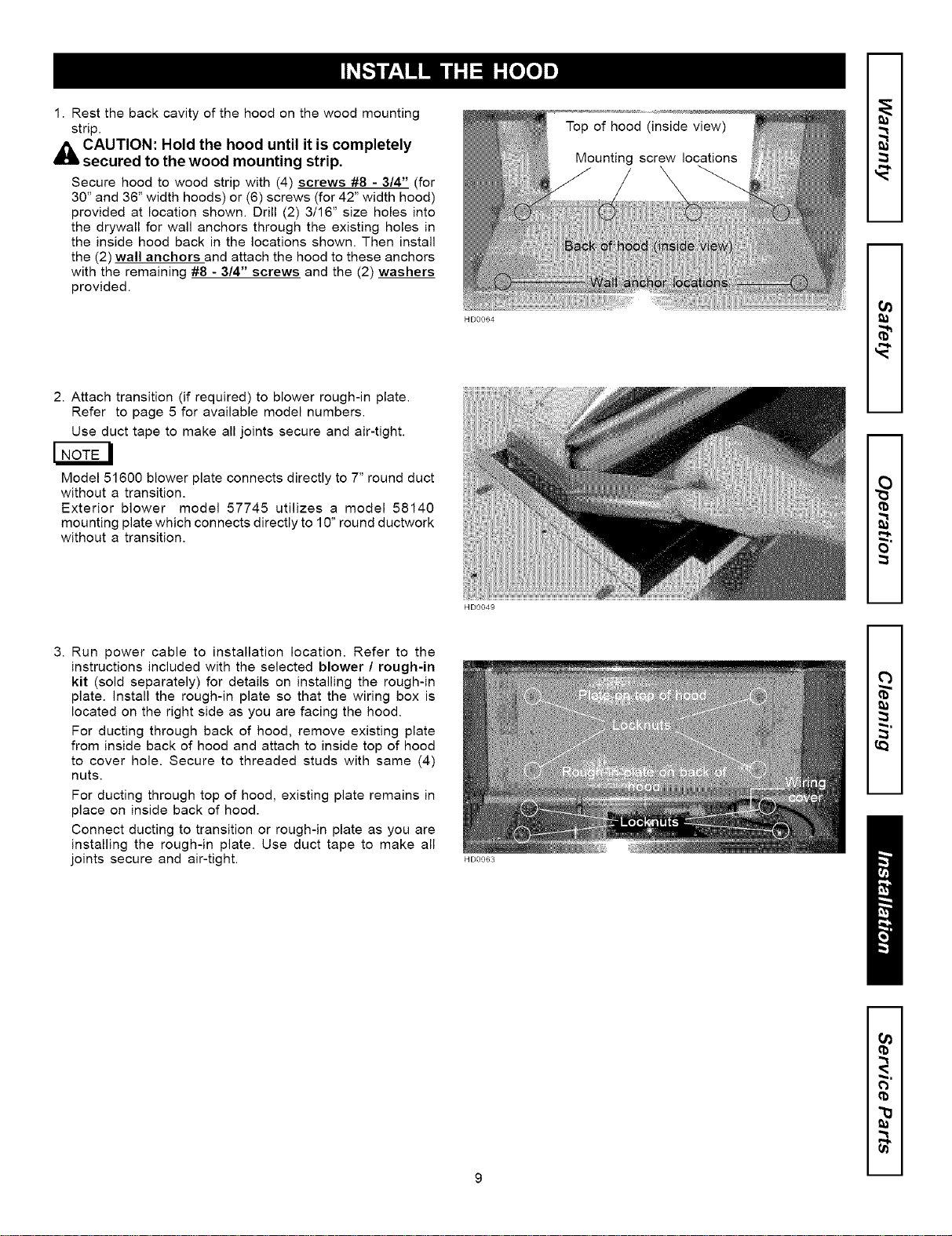
2. Measure and mark a level line on wall above cooktop
location for the wood mounting strip (see illustrations
to the right and under step 2 on page 7). Use #10-2" flat
head screws (included in the parts bag) to secure the mount-
to the drywall. Make sure to hit the wall studs.
CAUTION: Due to the weight of this hood,
ensure that the wood strip is attached to all of
the available wall studs (2 studs minimum for
the 30" hood, more as hood width increases);
not into drywall alone.
t3" (330 ram) or
19" (483 ram) from
ceiling see page 7
(38 mm)
HD0068A
1. Drywall
2. Wood Mounting Strip
3. Flat Head Screw
4. Wall Anchor Location
5. Outline of the Back of the Hood
6. Wall Studs
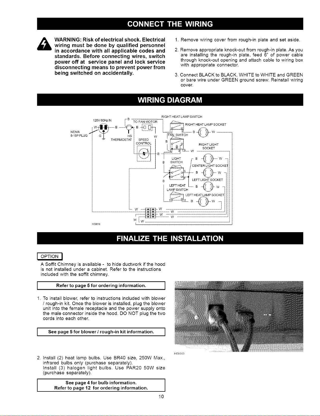
1.Restthebackcavityofthehoodonthewoodmounting
strip.
4_5 CAUTION: Hold the hood until it is completely
secured to the wood mounting strip.
Secure hood to wood strip with (4) screws #8 - 3/4" (for
30" and 36" width hoods) or (6) screws (for 42" width hood)
provided at location shown. Drill (2) 3/16" size holes into
the drywall for wall anchors through the existing holes in
the inside hood back in the locations shown. Then install
the (2) wall anchors and attach the hood to these anchors
with the remaining #8 - 3/4" screws and the (2) washers
provided.
2. Attach transition (if required) to blower rough-in plate.
Refer to page 5 for available model numbers.
Use duct tape to make all joints secure and air-tight.
Model 51600 blower plate connects directly to 7" round duct
without a transition.
Exterior blower model 57745 utilizes a model 58140
mounting plate which connects directly to 10" round ductwork
without a transition.
3. Run power cable to installation location. Refer to the
instructions included with the selected blower / rough-in
kit (sold separately) for details on installing the rough-in
plate, install the rough-in plate so that the wiring box is
located on the right side as you are facing the hood.
For ducting through back of hood, remove existing plate
from inside back of hood and attach to inside top of hood
to cover hole. Secure to threaded studs with same (4)
nuts.
For ducting through top of hood, existing plate remains in
place on inside back of hood.
Connect ducting to transition or rough-in plate as you are
installing the rough-in plate. Use duct tape to make all
joints secure and air-tight.
HD0064
HD0049
HD0063
Top of hood (inside view)
Mounting screw locations
m
m
O}
m
m
m
m
t3
O}
9 m
_i WARNING: Risk of electrical shock. Electricalwiring must be done by qualified personnel
in accordance with all applicable codes and
standards. Before connecting wires, switch
power off at service panel and lock service
disconnecting means to prevent power from
being switched on accidentally.
1. Remove wiring cover from rough-in plate and set aside.
2. Remove appropriate knock-out from rough-in plate. As you
are installing the rough-in plate, feed 6" of power cable
through knock-out opening and attach cable to wiring box
with appropriate connector.
3. Connect BLACK to BLACK, WHITE to WHITE and GREEN
or bare wire under GREEN ground screw. Reinstall wiring
cover.
NEMA
_15PPLUG
RIGHT HEAT LAMP SWITCH
120V 60Hz IN S_o FAN MOTOR RIGHT HEAT LAMP SOCKET
% THE HS W R,GHTL,GHT
RMOST_T _B W SOCKET
L:NT_CCKE]
°Ow
B LEFT LIGHT SOCKET
LAMP SWITCH "___
i
W[ w W
HE0018 I
I OPTION I
A Soffit Chimney is available - to hide ductwork if the hood
is not installed under a cabinet. Refer to the instructions
included with the soffit chimney.
I Refer to 5 for information. 1page
ordering
J
1. To install blower, refer to instructions included with blower
/ rough-in kit. Once the blower is installed, plug the blower
unit into the female receptacle and the power supply onto
the male connector inside the hood. DO NOT plug the two
cords into each other.
I See page 5 for blower / rough-in kit information. ]
2. Install (2) heat lamp bulbs. Use BR40 size, 250W Max.,
infrared bulbs only (purchase separately).
Install (3) halogen light bulbs. Use PAR20 50W size
(purchase separately).
See page 4for bulb information.
Refer to page 12 for ordering information.
10
HE0003
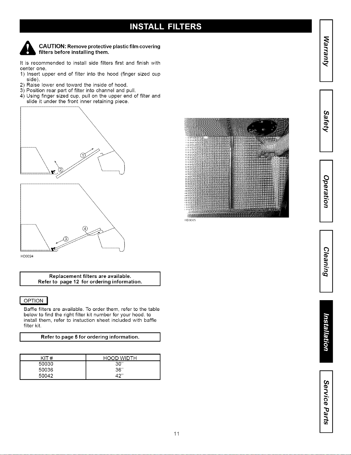
_ AUTION: Remove protective plastic film covering
filters before installing them.
It is recommended to install side filters first and finish with
center one.
1) insert upper end of filter into the hood (finger sized cup
side).
2) Raise lower end toward the inside of hood.
3) Position rear part of filter into channel and pull.
4) Using finger sized cup, pull on the upper end of filter and
slide it under the front inner retaining piece.
HD0065
m
m
O_
m
m
2
HD0024
I
Replacement filters are available. I
Refer to page 12 for ordering information.
I
I OPTION I
Baffle filters are available. To order them, refer to the table
below to find the right filter kit number for your hood. to
install them, refer to instuction sheet included with baffle
filter kit.
I Referto page 5fororderinginformation. I
KIT # HOOD WIDTH
50030 30"
50036 36"
50042 42"
m
m
13
O_
11 m
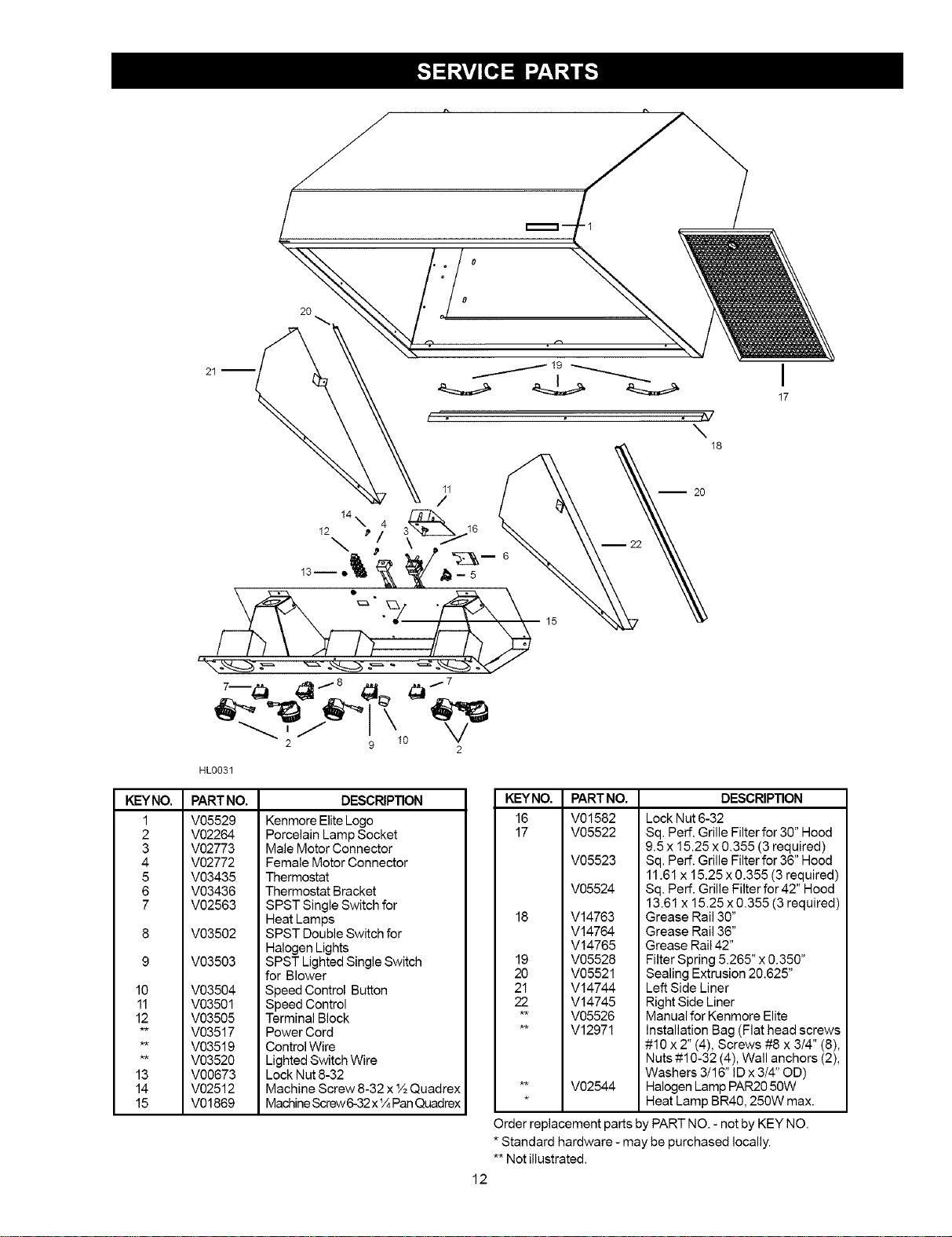
KEYNO,
1
2
3
4
5
6
7
10
11
12
13
14
15
0
20
HL0031
\
18
I
17
PARTNO.
V05529
V02264
V02773
V02772
V03435
V03436
V02563
V03502
V03503
V03504
V03501
V03505
V03517
V03519
V03520
V00673
V02512
V01869
DESCRIPTION
Kenmore Elite Logo
Porcelain Lamp Socket
Male Motor Connector
Female Motor Connector
Thermostat
Thermostat Bracket
SPST Single Switch for
Heat Lamps
SPST Double Switch for
Halogen Lights
SPST Lighted Single Switch
for Blower
Speed Control Button
Speed Control
Terminal Block
Power Cord
Control Wire
Lighted Switch Wire
Lock Nut 8-32
Machine Screw 8-32 x t½Quadrex
Machine Screw 6-32 x _/4Pan Quadrex
KEYNO,
16
17
18
19
2O
21
22
PARTNO.
V01582
V05522
V05523
V05524
V14763
V14764
V14765
V05528
V05521
V14744
V14745
V05526
V12971
DESCRIPTION
Lock Nut 6-32
Sq. Perf. Grille Filter for 30" Hood
9.5 x 15.25 x 0.355 (3 required)
Sq. Perf. Grille Filter for 36" Hood
11.61 x 15.25 x 0.355 (3 required)
Sq. Perf. Grille Filter for 42" Hood
13.61 x 15.25 x 0.355 (3 required)
Grease Rail 30"
Grease Rail 36"
Grease Rail 42"
Filter Spring 5.265" x 0.350"
Sealing Extrusion 20.625"
Left Side Liner
Right Side Liner
Manual for Kenmore Elite
Installation Bag (Flat head screws
#10 x 2" (4), Screws #8 x 3/4" (8),
Nuts #10-32 (4), Wall anchors (2),
Washers 3/16" ID x 3/4" OD)
** V02544 Halogen Lamp PAR20 50W
* Heat Lamp BR40, 250W max.
Order replacement parts by PART NO. - not by KEY NO.
* Standard hardware - may be purchased locally.
** Not illustrated.
12
Your Home
For repair-in your home-of all major brand appliances,
lawn and garden equipment, or heating and cooling systems,
no matter who made it, no matter who sold it!
::::::::::::::_ iiiiiiiiiiiiiiiii
For the replacement parts, accessories and
owner's manuals that you need to do-it-yourself. '_
For Sears professional installation of home appliances
and items like garage door openers and water heaters.
::::::::::::::_ HHHHHHHHii
1-800-4-MY-HOME ® (1-800-469-4663)
Call anytime, day or night (U.S.A. and Canada)
www.,ear,.comwww.,ear,.ca
Our Home =_
iiiiiiiiiiiiiii iiiiiiiiiiiiiiiii
For repair of carry-in items like vacuums, lawn equipment,
and electronics, call or go on-line for the location of your nearest --
Sears Parts & Repair Center.
1-800-488-1222
Call anytime, day or night (U.S.A. only)
w_,,.,ears.com ,,,,,,,,,,,,,,,_"
To1:urchase tpr°tecti°n800827 6655 (U.S.A.)agreement on 1prod.uctl800 361serviced6665(Canada)bYSears: __--
u_
Para pedir servicio de reparaciOn Au Canada pour service en fran(_ais: _"
a domicilio, y pare ordenar piezas: 1.800.LE.FOYERMC
1"888"SU'HOGARSM (1-800-533-6937) ,,,,,,,,,,,,,,,o"
(1-888-784-6427) www.sears.ca :=
i
TM
® Registered Trademark / Trademark / SMService Mark of Sears, Roebuck and Co.
TM
® Marca Registrada / Marca de Fabrica / SMMarca de Servicio de Sears, Roebuck and Co.
MC MD
Marque de commerce / Marque deposee de Sears, Roebuck and Co. ® Sears, Roebuck and Co.
13
SECCI6N PAGJNA
Garantia.................................................................................14
hstruccionesde seguridad..................................................14
©peraci6n ..............................................................................15
Limpieza ................................................................................I5
Piezas incluidas....................................................................16
Piezas non incbidas ............................................................. 16
Herramientas necesanas ..................................................... 16
Sistema de ia campana Serie 51000 ................................... 17
Cuadro de equivalencia de largo de conducto ................... 18
Prepare Ia Iocalizaci6n para la campana ............................ 19
Prepare la campana ............................................................. 20
Instab la campana ................................................................ 21
Conecte et cabIeado ............................................................. 22
Esquema eI6ctrico ................................................................ 22
Terminar Ia instalaci6n .......................................................... 22
Instab los filtros .................................................................... 23
Piezas de servicio ................................................................. 24
Si dentro de 1 abe de Ia fecha de la instalaci6n, cuaJquier parte
de esta campana de cocina deja de funcionar en forma
apropiada debido a defecto en ei material o la mane de obra,
Sears repararA Ia pieza afectada o proveerA e instalara una
pieza nueva libre de cargo.
GARANTIA COMPLETA DE 30 BiAS EN EL ACABADO EN
PJEZAS MET.,_LICAS PJNTADAS O ABRILLANTADAS
Si dentro de 30 dias de la fecha de Ia instalacidn, el acabado de
cualquier parte metAlica pintada o abrillantada perteneciente a
esta campana de cocina aparece con defecto en el material o
la mano de obra, Sears proveerA e instalarb, una pieza nueva
libre de cargo.
EL SERVICIO DE GARANTIA SE OBTJENE PONtg:NDOSE EN
CONTACTO CON EL CENTRO DE SERVICJO O
DEPARTAMENTO SEARS M.,_SCERCANO EN LOS ESTADOS
UNIDOS.
Esta garantia es vaiedera unicamente si este producto se tiene
en uso dentro de los Estados UnJdos, Esta garantia le confiere
derechos Iegales especificos y Ud. puede tener ademb,s otros
derechos que vadan de estado a estado.
Sears, Roebuck and Co., Dept. 817WA, Noffman Estates, IL 60179
ADVERTENCIA
PARA REDUCIR EL RmESGO DE INCENDtO, CROQUE ELECTRmCO, O
LESION A PERSONAS, PROCURE LO SIGUIENTE:
1. Utilice esta unidad s61o en ia manera prescrita pot el fabricante. Si
fiene usted alguna pregunta, comuniquese con el fabricante a la
direcci6n indicados en la garantia.
2. Antes de efectuar aigOn servicio o iimpieza, se debe desconectar la
corriente electrica en el armario de circuitos y asegurarlo con IIave
para evitar que ta corriente sea conectada accidentalmente. Cuando
el dispositivo para desconectar ei servicio electrico no puede ser
cerrado con algQn tipo de traba, sujete fuertemente al panei de servicio,
una etiqueta de advertencia prominente.
3. Todo trabaio de instaIaci6n y cableado eiectrico debe ser reaJizado
por personal calificado y de acuerdo con todos los c6digos y normas
pertinentes, incluyendo los c6digos y normas reiacionados con
construcci6n clasificada para incendio.
4. Aire suficiente es necesario para facilitar Ia combusti6n adecuada y
la salida apropiada de gases por Ia chimenea de Ia unidad y para
evitar corrientes de aire invertidas. Siga las instrucciones y medidas
de seguridad deI fabricante dei equipo y ios publicados por la
Asociael6n nacionaI de protecci6n contra incendidos (NFPA pot sus
siglas in Ingles), y la Sociedad americana de ingenieros de calefacel6n,
refrigeraci6n y aire acondielonado (ASHRAE por sus siglas in Inglg,s),
y los reglamentos de seguridad locales.
5. Acortaroperforariaparedoeltecho, noda_eelcableadoei6ctrico
ni otros servicios pObticos ocuitos a la vista.
6. No utilice este ventilador con ningQn dispositivo de una control de
veloeldad de estado s6iido adicionaL
7. Los abanicos con ducto deber_Snsiempre tener una salida hacia el exterbr.
8. Para reduelr el riesgo de incendio, use s61o ductos de metal
9. Esta unidad se debe instalar con tierra efectiva.
PARA REDUCIR ELRIESGO DE INCENDIO DE GRASA EN LASUPERFICIE
DE LA ESTUFA:
1. Nodejenuncalosaparatosdecocersin vigilenciaafuegovivo. Los
desbordamientos producen humo y derrames grasiendos que pueden
inflamarse. Caliente e! aceite despacio, a fuego lento o mediano.
2. Ponga en marcha siempre la campana al cocinar a temperaturas elevadas
o aI cocinar alimentos flameados.
3. Limpieconfrecuencialosventiladores. Nodebepermitirquelagrasa
se acumule en el ventilador ni en el filtro.
4. Utilice un sart6n de tama_o adecuado. Siempre utilice el utensilio
adecuado aI tamaBo del elemento de superficie.
14
ADVERTENCIA _ _,
PARA EVITAR RESGO DE LESIONES PERSONALES EN CASO DE
INCENDIO DE GRASA EN LASUPERFICE DE LA ESTUFA, OBSERVE
LO SIGUIENTE:*
1. Cubra y sofoque las ilamas con una tapa aiustada, azafate de hornear
gailetas, o azafate de metal, y luego apague el calentador. TENGA
CUIDADO PARA EVITAR QUEMADURAS. Si tas llamas no se apagan
inmediatamente, HAY QUE EVACUAR Y LLAMAR LOS BOMBEROS.
2. NUNCAALCE UNASARTf_N QUETENGALLAMAS -Ustedse puedequems_se.
3. NOUTILICEAGUA, incluyendotrapos, lavaplatos mojadosotoatlas_
puede que occuran explosiones de vapor vioIentas.
4. Utiibe un extinguidor SOLAMENTE si:
A. Usted sabe que tiene un extinguidor de clas ABC y !o sabe utiIizar.
B. El incendio es peque_o y contenido dentro det area donde se inici6.
Q Los bomberos han eldo avisados.
D. Usted puede combatJr e! incendio con una salida a su espalda.
* Basado en tas recomendaciones para "Seguridad en la Cocina"
pubticadas pot la NFPA de Ios EEUU.
PRECAUCION
I. S61o para uso de ventilaci6ngeneral.No se use paraextramateriales
o vapores peligrososo explosivos.
2. Para evitardaBos alcojinentedeJ motor y/o impulsores ruidososo
desequilibrados,mantenga lafuentede potencialejosde roeiosde
pared seca,de polvode construeci6n,etc.
3. Elmotordelacampana tieneun dispositivocontrasobreeargast6rmicas
que apaga elmotor en forma automaticasi@ste se sobrecalientaEl
motorvolver&arrancarcuando se enfrie.Sielmotorsigueapagandose,
haga verificar Ia campana.
4. Para !ograr una mejor captura de las impurezas producidas al coelnar,
la parte inferior de la campana deber_ estar a un minimo de 24" y un
m_4ximo de 30" sobre el nivet Ia superficie para cocinar.
5. A fin de reducir los riesgos de incendJo y para bien evacuar el aire de salida,
&seg{Sresedeevacuar el aireelexterior _Noevacue el aireenespasies lim_dos
c_omoel intedor de la paredes o deltecho e eneldesvb_n,falso techo ogaraje.
6. Este producto esta equipado de un termostato que puede hacer partir et
ventitador automaticamente. Para evitar los riesgo de da_o, apague ta
corrbnte de panel el6ctrico y elerre con candado oafiche una adver[anela
en et panel para prevenir que lacampana funcione automaticamente.
7. Para reducir et riesgo de incendio y descarga electrica, este campana
Kenmore Elite Series 51000 debe ser instabda con ventiladores modebs
51200, 51600 o 57745 solamente. Otros ventiladores no debe ser utilisado.
(Ventiladores vendidos separadamente.)
8. Utilice s61o con un conjunto autorizado de conexi6n con cord6n.
9. Por favor, Iea la etiqueta de espeelficaciones en el producto para mayor
informaci6n y requisito.
Siemprehacerfuncionarlacampanaantesdecomenzara
cocinarafindeestablacerunacirculaci6ndeaireenlacocina.
Dejeigualmentefuncionarlacampanaalgunosminutos
despuesdequeparedecocinarafindelimpiarelaire.Esto
ayudaaconcervarlacocinamaslimpiayunairepuro.
O 4-E" =
I
3
2
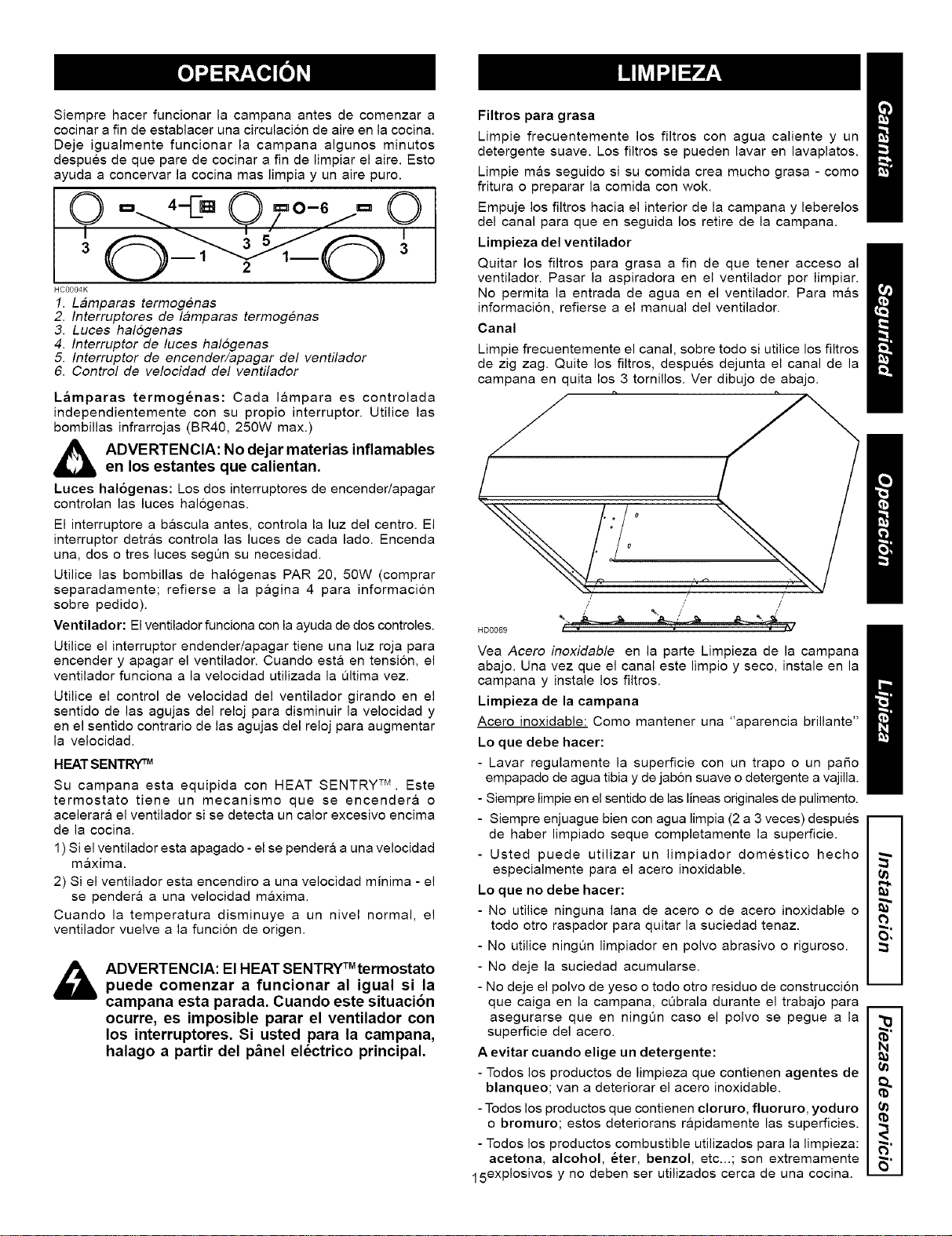
HCOOO4K
1. Lamparas tormogenas
2. Interruptores de lamparas termogenas
3. Luces hal6genas
4. Interruptor de luces halogenas
5. Interruptor de encender/apagar del ventilador
6. Control de velocidad del ventilador
L_mparas termog_nas: Cada I&mpara es controlada
independientemente con su propio interruptor. Utilice las
bombillas infrarrojas (BR40, 250W max.)
_,_ DVERTENClA: No dejar materias inflamables
en los estantes que calientan.
Luces hal6genas: Los dos interruptores de encender/apagar
controlan las luces hal6genas.
El interruptore a bascula antes, controla la luz del centro. El
interruptor detras controla las luces de cada lado. Encenda
una, dos o tres luces segQn su necesidad.
Utilice las bombillas de halogenas PAR 20, 50W (comprar
separadamente; refierse a la p&gina 4 para informacion
sobre pedido).
Ventilador: El ventilador funciona con la ayuda de dos controles.
Utilice el interruptor endender!apagar tiene una luz roja para
encender y apagar el ventilador. Cuando est& en tension, el
ventilador funciona a la velocidad utilizada la 01tima vez.
Utilice el control de velocidad del ventilador girando en el
sentido de las agujas del reloj para disminuir la velocidad y
en el sentido contrario de las agujas del reloj para augmentar
la velocidad.
HEAT SENTRY "rM
Su campana esta equipida con HEAT SENTRY TM. Este
termostato tiene un mecanismo que se encender& o
acelerara el ventilador si se detecta un calor excesivo encima
de la cocina.
1) Si el ventilador esta apagado - el se pender& a una velocidad
maxima.
2) Si el ventilador esta encendiro a una velocidad minima - el
se pendera a una velocidad maxima.
Cuando la temperatura disminuye a un nivel normal, el
ventilador vuelve a la funcion de origen.
TM
ADVERTENClA: El HEAT SENTRY termostato
puede comenzar a funcionar al igual si la
campana esta parada. Cuando este situacion
ocurre, es imposible parar el ventilador con
los interruptores. Si usted para la campana,
halago a partir del p_nel el_ctrico principal.
Filtros para grasa
Limpie frecuentemente los filtros con agua caliente y un
detergente suave. Los filtros se pueden lavar en lavaplatos.
Limpie mas seguido si su comida crea mucho grasa - come
fritura o preparar la comida con wok.
Empuje los filtros hacia el interior de la campana y leberelos
del canal para queen seguida los retire de la campana.
Limpieza del ventilador
Quitar los filtros para grasa a fin de que tener acceso al
ventilador. Pasar la aspiradora en el ventilador por limpiar.
No permita la entrada de agua en el ventilador. Para m&s
informacion, refierse a el manual del ventilador.
Canal
Limpie frecuentemente el canal, sobre todo si utilice los filtros
de zig zag. Quite los filtros, despues dejunta el canal de la
campana en quita los 3 tornillos. Ver dibujo de abajo.
t, t,
/ /
/' ,/
HD0069 l
Yea Acero inoxidable en la parte Limpieza de la campana
abajo. Una vez que el canal este limpio y seco, instale en la
campana y instale los filtros.
Limpieza de la campana
Acero inoxidable: Como mantener una "aparencia brillante"
Lo que debe hacer:
- Lavar regulamente la superficie con un trapo o un paso
empapado de agua tibia y de jab6n suave o detergente a vajilla.
- Siempre limpie en el sentido de las lineas originales de pulimento.
- Siempre enjuague bien con agua limpia (2 a 3 veces) despues
de haber limpiado seque completamente la superficie.
- Usted puede utilizar un limpiador domestico hecho
especialmente para el acero inoxidable.
Lo que no debe hacer:
- No utilice ninguna lana de acero o de acero inoxidable o
todo otto raspador para quitar la suciedad tenaz.
- No utilice ningun limpiador en polvo abrasivo o riguroso.
- No deje la suciedad acumularse.
- No deje el polvo de yeso o todo otro residuo de construccion
que caiga en la campana, cObrala durante el trabajo para
asegurarse queen ningQn caso el polvo se pegue a la
superficie del acero.
A evitar cuando elige un detergente:
- Todos los productos de limpieza que contienen agentes de
blanqueo; van a deteriorar el acero inoxidable.
-Todos los productos que contienen cloruro, fluoruro, yoduro
o bromuro; estos deteriorans r&pidamente las superficies.
- Todos los productos combustible utilizados para la limpieza:
acetona, alcohol, 6ter, benzol, etc...; son extremamente
15 expl°siv°s Y no deben ser utilizados cerca de una cocina.
ta
O,
m
u
ta
ta
t,a
R"
6"
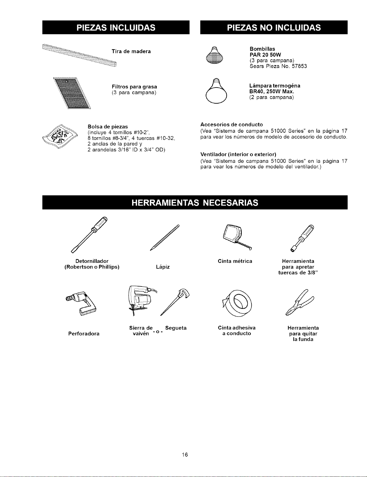
Tira de madera
.....
Filtros para grasa
(3 para campana)
Bombillas
PAR 20 50W
(3 para campana)
Sears Pieza No. 57853
(_ L_mpara termog_na
BR40, 250W Max.
(2 para campana)
Bolsa de piezas
(incluye 4 tornillos #10-2",
8 tornillos #8-3/4", 4 tuercas #10-32,
2 anclas de la pared y
2 arandelas 3/16" ID x 3/4" OD)
Accesorios de conducto
(Yea "Sistema de campana 51000 Series" en la p&gina 17
para vear los nQmeros de modelo de accesorio de conducto.
Ventilador (interior o exterior)
(Yea "Sistema de campana 51000 Series" en la p&gina 17
para vear los nQmeros de modelo del ventilador.)
/ / Q /
Detornillador Cinta m_trica Herramienta
(Robertson o Phillips) L&piz para apretar
tuercas de 3/8"
Sierra de Segueta Cinta adhesiva Herramienta
Perforadora - - - o -
vaiven a conducto para quitar
la funda
16
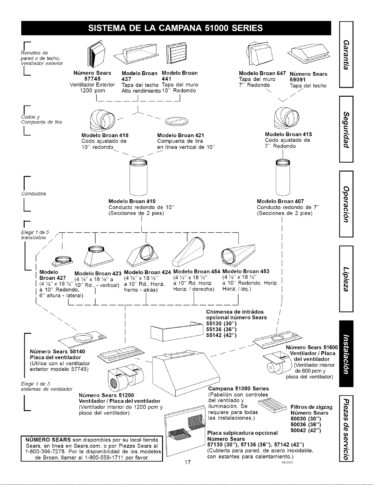
F
Remates de
pared o de techo,
Ventilador exterior
L
F
Codes y
Compuerta de tira
L
Nt_mero Sears
57745
Ventilador Exterior
1200 pcm
I
Modelo Broan Modelo Broan
437 441
Tapa del techo Tapa del muro
Alto rendimiento 10" Redonda
I J
J
Modelo Broan 418
Coda ajustada de
10" redanda
I
J
v
Modelo Broan 421
Compuerta de tira
en linea vertical de 10"
Modelo Broan 647 Nt_mero Sears
Tapa del muro 59091
7" Redando Tapa del techo
\
.j
J
Modelo Broan 415
Codo ajustado de
7" Redondo
I
F
Conductos
L
F
Elegir 1de 5 /7
transici6ns
/
¢
I
r
Modelo Broan 410
Conducto redondo de 10"
(Secciones de 2 pies)
I
I
T
Modelo Broan 407
Conducto redondo de 7"
(Secciones de 2 pies)
I Modelo Modelo Broan 423 Modelo Broan 424 Modelo Broan 454 Modelo Broan 453
Broan 427 (4 ½" x 18 ½" a (4 ½" x 18 ½" (4 ½" x 18 ½" (4 ½" x 18 ½"
I (4 ½" x 18 ½"_ 0" Rd. - vertical) a 10" Rd., Horiz. a 10" Rd. Horiz. a 10" Redanda, Hariz.
i'--.6 a tura - _tera)a10'' Reaenae, 1' frente - itr,s ) Horiz. / derecha Heriz. i izq.)
Nt_mero Sears 58140
Placa del ventilador
(Utilice con el ventiladar
exterior modelo 57745)
Elegir 1 de 3
sistemas de ventilador
L
Chimenea de intr&dos
opcional nt_mero Sears
_ 55130 130") /__
55136 (36")
55142 (42")
// o Sears 51600
__._ /_ J _J-_Ventilador / Placa
"--_1_ \ _ _ del ventilador
_ _ \ _ ('_'_) (Ventilador interior
I \ \ _ de 600 pcm y
placa del ventilador)
_J-_ Campana 51000 Series
Nt_mero Sears 51200 _ (Pabellon con controles
Ventilador /Placa del ventilador del ventilado y
(Ventilador interior de 1200 pcm y iluminacion. Se
placa del ventilador) requiere para todas
las instalaciones.)
J OMERO SEARS son disponibles par su local tienda
Sears, en linea en Sears.com, o per Piezas Sears al
1-800-366-7278. Por la disponibilidad de los modelos
de Braan, Ilamar al 1-800-558-1711 per favor.
17
Filtros de zigzag
Nt_mero Sears
50030 (30")
50036 (36")
50042 (42")
Placa salpicadura opcional
N_mero Sears
57130 (30"), 57136 (36"), 57142 (42")
(Cubierta para pared, de acero inoxidable,
con estantes para calentamiento.)
HL0032
63
m
m
m
m
2
O,
m
m
N
m
u
N
F,"
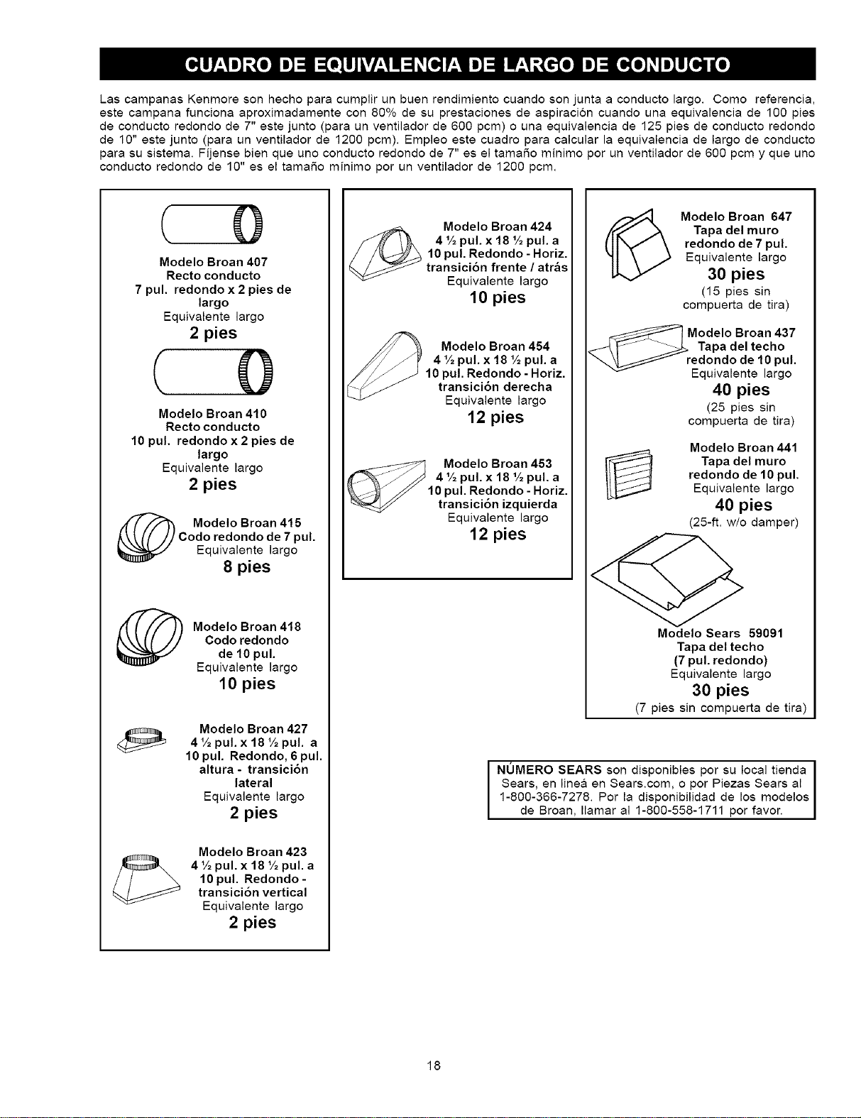
Las campanas Kenmore son hecho para cumplir un buen rendimiento cuando son junta a conducto largo. Como referencia,
este campana funciona aproximadamente con 80% de su prestaciones de aspiracion cuando una equivalencia de 100 pies
de conducto redondo de 7" este junto (para un ventilador de 600 pcm) o una equivalencia de 125 pies de conducto redondo
de 10" este junto (para un ventilador de 1200 pcm). Empleo este cuadro para calcular la equivalencia de largo de conducto
para su sistema. Fijense bien que uno conducto redondo de 7" es el tamaSo minimo por un ventilador de 600 pcm y que uno
conducto redondo de 10" es el tamaSo minimo por un ventilador de 1200 pcm.
Modelo Broan 407
Recto conducto
7 pul. redondo x 2 pies de
largo
Equivalente largo
2 pies
( 0
Modelo Broan 410
Recto conducto
10 pul. redondo x 2 pies de
largo
Equivalente largo
2 pies
_) Modelo Broan 415
Codo redondo de 7 pul.
Equivalente largo
8 pies
Modelo Broan 418
Codo redondo
de 10 pul.
Equivalente largo
10 pies
Modelo Broan 427
4 tA pul. x 18 1Apul. a
10 pul. Redondo, 6 pul.
altura- transici6n
lateral
Equivalente largo
2 pies
Modelo Broan 423
4 tA pul. x 18 tA pul. a
10 pul. Redondo -
transici6n vertical
Equivalente largo
2 pies
Modelo Broan 424
4 1Apul. x 18 1Apul. a
10 pul. Redondo - Horiz.
transici6n frente / atr&s
Equivalente largo
10 pies
Modelo Broan 454
4 1Apul. x 18 1Apul. a
10 pul. Redondo - Horiz.
transici6n derecha
Equivalente largo
12 pies
Modelo Broan 453
4 V2pul. x 18 1Apul. a
10 pul. Redondo - Horiz.
transici6n izquierda
Equivalente largo
12 pies
(_ Modelo Broan 647
Tapa del muro
redondo de 7 pul.
Equivalente largo
30 pies
(15 pies sin
compuerta de tira)
Modelo Broan 437
Tapa del techo
redondo de 10 pul.
Equivalente largo
40 pies
(25 pies sin
compuerta de tira)
Modelo Broan 441
Tapa del muro
redondo de 10 pul.
Equivalente largo
40 pies
(25-ft. w/o damper)
Modelo Sears 59091
Tapa del techo
(7 pul. redondo)
Equivalente largo
30 pies
(7 pies sin compuerta de tira)
NUMERO SEARS son disponibles por su local tienda i
Sears, en line& en Sears.corn, o por Piezas Sears al i
1-800-366-7278. Por la disponibilidad de los modelos
de Broan, amar a 1-800-558-1711 por favor.
18
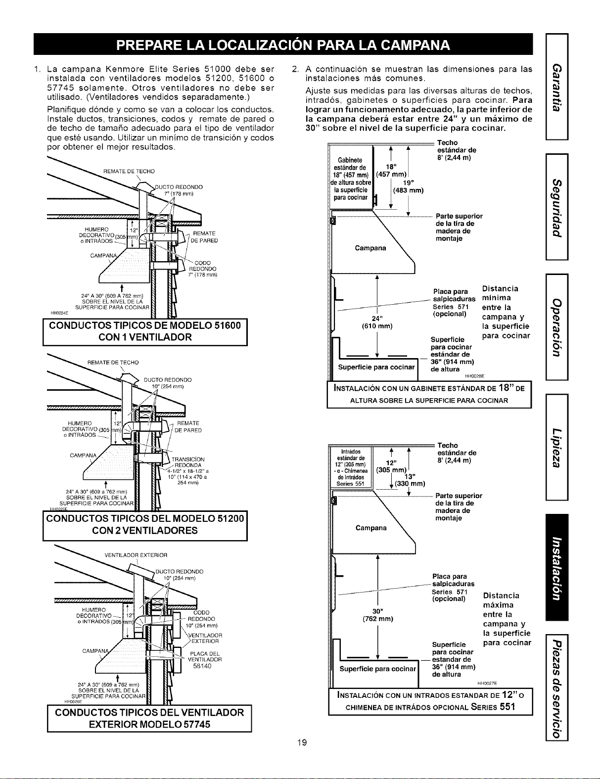
1. La campana Kenmore Elite Series 51000 debe ser
instalada con ventiladores modelos 51200, 51600 o
57745 solamente. Otros ventiladores no debe ser
utilisado. (Ventiladores vendidos separadamente.)
Planifique donde y como se van a colocar los conductos.
Instale ductos, transiciones, codos y remate de pared o
de techo de tamaSo adecuado para el tipo de ventilador
que este usando. Utilizar un minimo de transicion y codos
per obtener el mejor resultados.
REMATEDETECHO
\
7" (178 ram)
HUMERO
DECORATJVO 305 REMATE
oINTRADOS_ DEPARED
REDONDO
7"(178mm)
t
24" A 30" (009 A 762 mm)
SOBRE EL NIVEL DE LA
SUPERFtCIE PARA COCINAR
CONDUCTOS TIPICOS DE MODELO 51600
CON 1 VENTILADOR
REMATEDETECHO
\
DUCTO REDONDO
(254 mm)
HUMERO REMATE
DECORATIVO 305 DE PARED
olNTRADOS_
CAMPANA
t
24" A 30" (609 a 762 mm)
SOBRE EL NIVEL DE LA
SUPERFICIE PARA COCINAR
/ REDONDA
4/2" x 18-1/2" a
10" (1t4 x 470 a
254 ram)
CONDUCTOS TIPICOS DEL MODELO 51200
CON 2 VENTILADORES
VENTILADOR EXTERIOR
DUCTO REDONDO
10"(254mm)
HUMERO CODO
DECORATWO
o INTRADOS - REDONDO
10" (254 mm)
t
24" A 30" (609 a 762 mm)
SOBRE EL NIVEL DE LA
SUPERFICIE PARA COCtNAR
_EXTERIOR
PLACA DEL
VENTILADOR
58140
I CONDUCTOS TIPICOS DEL VENTILADOREXTERIOR MODELO 57745
A continuacion se muestran las dimensiones para las
instalaciones m&s comunes.
z.g
Ajuste sus medidas para las diversas alturas de techos, :_
intrados, gabinetes o superficies para cocinar. Para
Iograr un funcionamento adecuado, la parte inferior de
la campana deber& estar entre 24" y un m_ximo de
30" sobre el nivel de la superficie para cocinar.
Techo
I est_indar deGabinete 8' (2,44 m)
estbndar de |
t8" (457ram) I
dealtura s0breI 19"
la superficie I. I (483 ram) ,q)
paracocinar p ; _
_=
Parte superior _"
de la tira de _"
madera de _..
montaje
Placa para Distancia
salpicaduras minima
f,.%
Series 571 entre la
24" (opcional) campana y (b
(610 mm) la superficie
Superficie para cocinar
para cocinsr _
_ est_ndar de
I 36" (914 mm)
Superficie para cocinar de altura
HH0028E
INSTALACION CON UN GABINETE ESTANDAR DE 18" DE I --
ALTURA SOBRE LA SUPERFICIE PAPA COCINAR
I
Techo "_"
Intrados II _ _' est_ndar de _"
esandarde - / 8' (2,44 m) N
12" 305mm 12" |
-0-Chimenea (305 mm) _
deintrados II | 13"
Series5511, _,(330 mm)
/
Parte superior
de la tira de
madera de
montaje
T
-- | Placa para
_ salpicaduras
I Series 571
I
(opcional)
30"
(762 ram)
Distancia
m&xima
entre la
campana y
la superficie
Superficie para cocinar
para cocinar
-- estandar de
36" (914 mm)
de altura
HH0027E
m m
Superficie para cocinsr
19
INSTALACION CON UN INTRADOS ESTANDAR DE 12" o
CHIMENEA DE INTR/_,DOS OPCIONAL SERIES 551
m
u
m
(b
L-"
R"
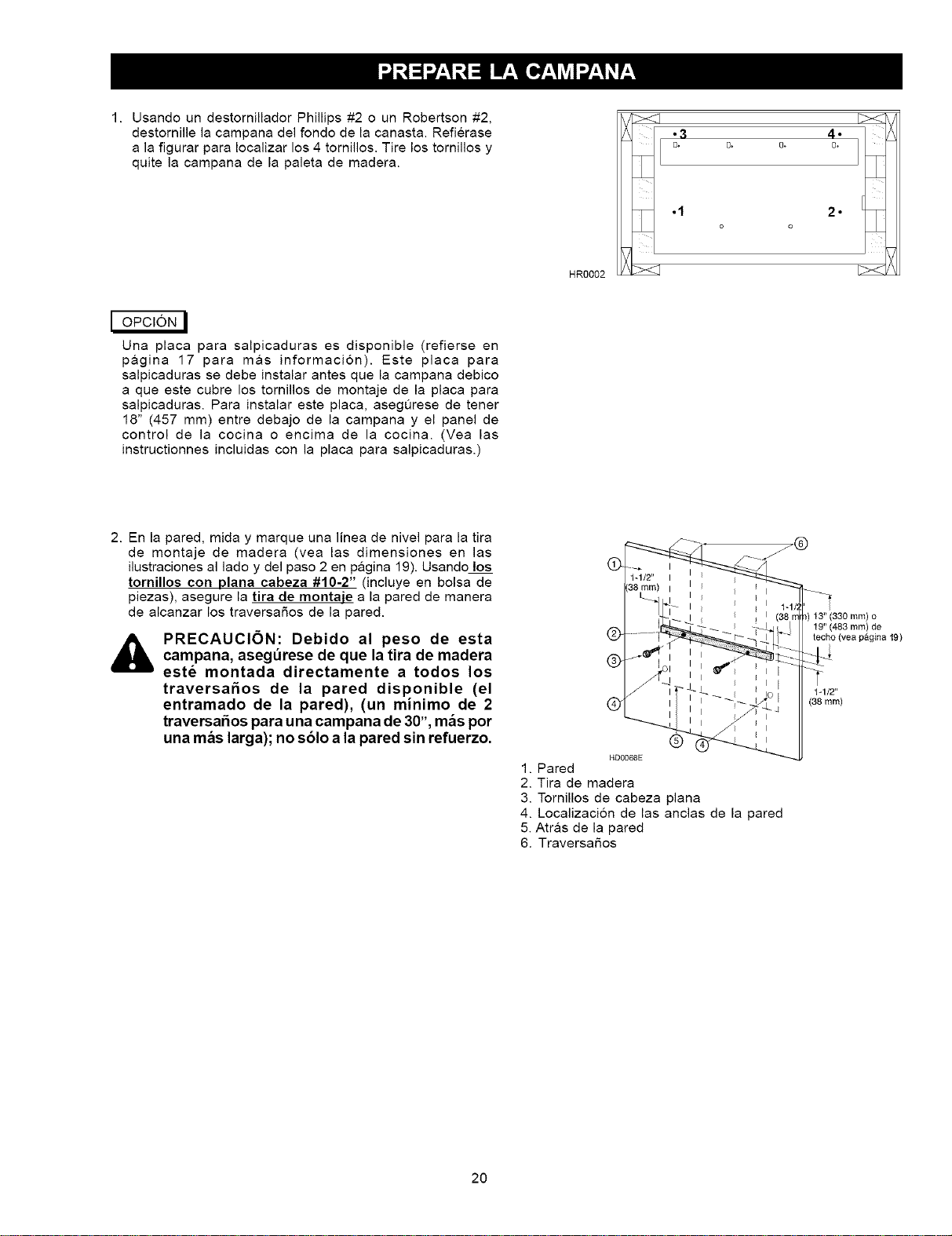
1. Usando un destornillador Phillips #2 o un Robertson #2,
destornille la campana del fondo de la canasta. Refierase
a la figurar para Iocalizar los 4 tornillos. Tire los tornillos y
quite la campana de la paleta de madera.
.3
0,
.1
HR0002
4.
0, 0- 0*
2"
o o
I OPCION I
Una placa para salpicaduras es disponible (refierseen
p&gina 17 para mas informacion). Este placa para
salpicaduras se debe instalar antes que la campana debico
a que este cubre los tornillos de montaje de la placa para
salpicaduras. Para instalar este placa, asegurese de tener
18" (457 mm) entre debajo de la campana y el panel de
control de la cocina o encima de la cocina. (Vea las
instructionnes incluidas con la placa para salpicaduras.)
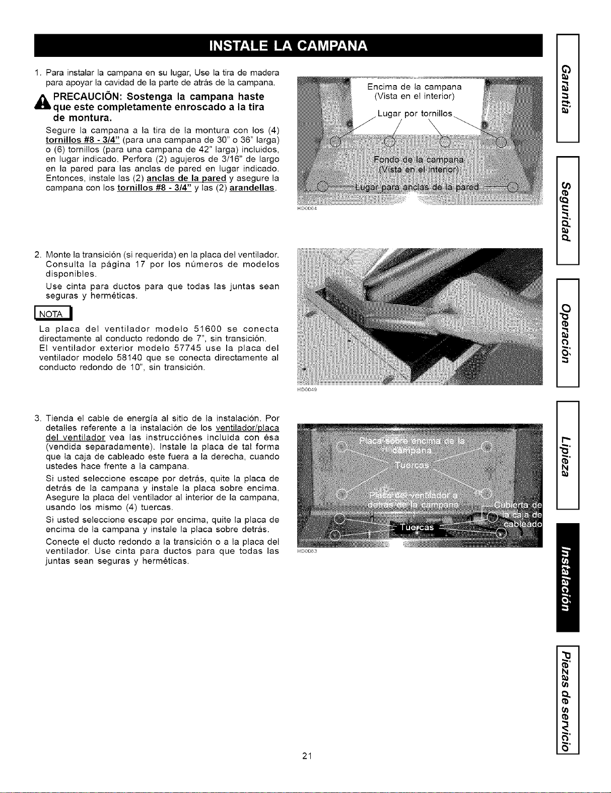
2. En la pared, mida y marque una linea de nivel para la tira
de montaje de madera (vea las dimensiones en las
ilustraciones al lado y del paso 2 en pagina 19). Usando los
tomillos con plana cabeza #10-2" (incluye en bolsa de
piezas), asegure la tira de montaje a la pared de manera
de alcanzar los traversaSos de la pared.
_b PRECAUCI6N: Debido al peso de esta
campana, asegt_rese de que la tira de madera
este montada directamente a todos los
traversaSos de la pared disponible (el
entramado de la pared), (un minimo de 2
traversa_os para una campana de 30", m_s por
una mas larga); no s61oa la pared sin refuerzo.
HD0068E
1. Pared
2. Tira de madera
3. Tornillos de cabeza plana
4. Localizacion de las anclas de la pared
5. Atras de la pared
6. TraversaSos
3) 13" (330 ram) o
19" (483 ram) de
techo (yea p&gina 19)
1 1/2"
(38 mm)
20
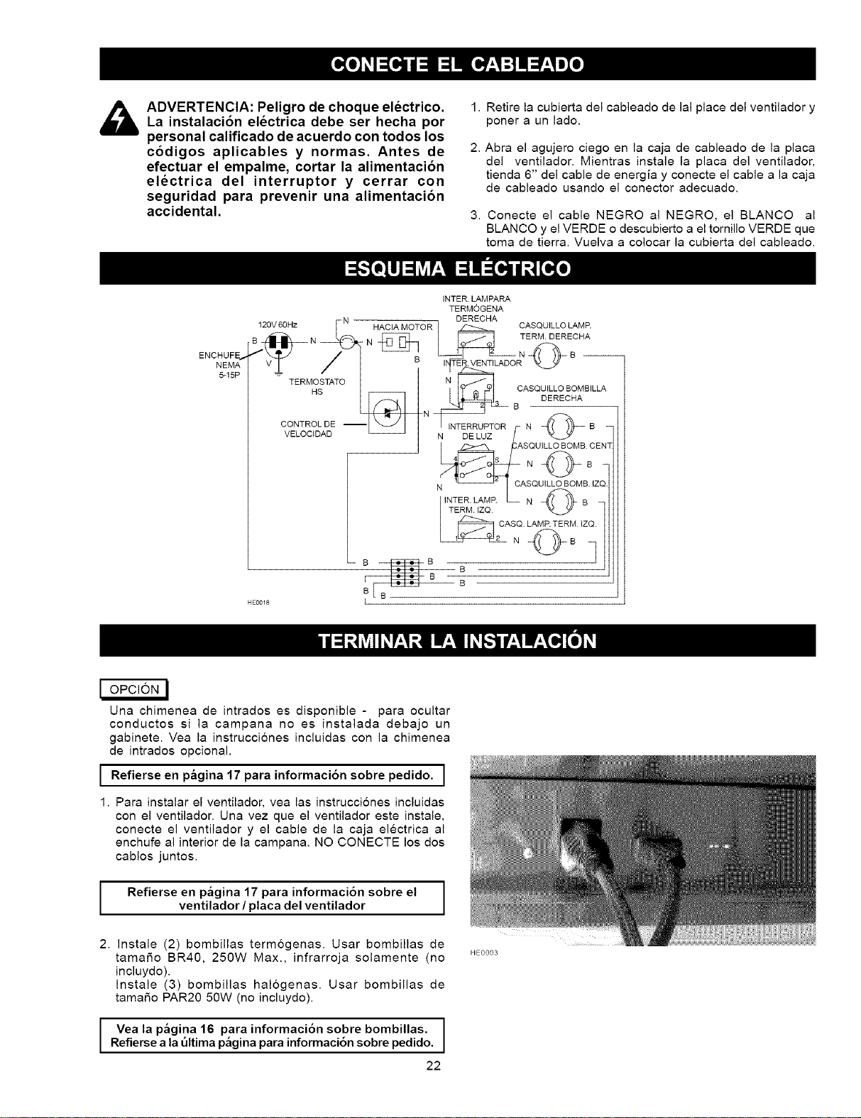
1.Parainstalarlacampanaensulugar,Uselatirademadera
paraapoyarlacavidaddelapartedeatr&sdelacampana.
PRECAUCION: Sostenga la campana haste
que este completamente enroscado a la tira
de montura.
Segure la campana a la tira de la montura con los (4)
tornillos #8 - 3/4" (para una campana de 30" o 36" larga)
o (6) tornillos (para una campana de 42" larga) incluidos,
en lugar indicado. Perfora (2) agujeros de 3/16" de largo
en la pared para las anclas de pared en lugar indicado.
Entonces, instale las (2) anclas de la pared y asegure la
campana con los tornillos #8 - 3/4" y las (2) arandellas.
2. Monte la transicion (si requerida) en la placa del ventilador.
Consulta la pagina 17 por los n0meros de modelos
disponibles.
Use cinta para ductos para que todas las juntas sean
seguras y hermeticas.
La placa del ventilador modelo 51600 se conecta
directamente al conducto redondo de 7", sin transici6n.
El ventilador exterior modelo 57745 use la placa del
ventilador modelo 58140 que se conecta directamente al
conducto redondo de 10", sin transicion.
3. Tienda el cable de energia al sitio de la instalacion. Por
detalles referente a la instalacion de los ventilador/placa
del ventilador vea las instrucciones incluida con esa
(vendida separadamente). Instale la placa de tal forma
que la caja de cableado este fuera a la derecha, cuando
ustedes hace frente a la campana.
Si usted seleccione escape por detras, quite la placa de
detr&s de la campana y instale la placa sobre encima.
Asegure la placa del ventilador al interior de la campana,
usando los mismo (4) tuercas.
Si usted seleccione escape por encima, quite la placa de
encima de la campana y instale la placa sobre detr&s.
Conecte el ducto redondo a la transici6n o a la placa del
ventilador. Use cinta para ductos para que todas las
juntas sean seguras y hermeticas.
HD0064
HD0049
HD0063
Encima de la campana
(Vista en el interior)
por tornillos
m
m
m
m
2
O,
m
m
"S"
N
21
m
(a
(a
,_ ADVERTENCIA: Peligro de choque electrico.La instalacibn electrica debe ser hecha por
personal calificado de acuerdo con todos los
codigos aplicables y normas. Antes de
efectuar el empalme, cortar la alimentacion
electrica del interruptor y cerrar con
seguridad para prevenir una alimentacion
accidental.
1. Retire la cubierta del cableado de lal place del ventilador y
poner a un lado.
2. Abra el agujero ciego en la caja de cableado de la placa
del ventilador. Mientras instale la placa del ventilador,
tienda 6" del cable de energia y conecte el cable a la caja
de cableado usando el conector adecuado.
3. Conecte el cable NEGRO al NEGRO, el BLANCO al
BLANCO y el VERDE o descubierto a el tomillo VERDE que
toma de tierra. Vuelva a colocar la cubierta del cableado.
ENCHUFE_,
NEMA
5-15P
INTER. LAMPARA
TERMOGENA
120V60Hz N HAClA MOTOR DERECHA CASQUILLO LAMP.
V_. / [ B I_TER_TILADOR
TERMOSTATO N
H!:_ _ _ BOASQUILLOBOMBILLADEREOHA
CONTRO N f- N _ B
VELOC+DAD _ I N DELUZ /
I /:ASOUILLOBOMBOE
+N; / ASOU+L'-OBOM°.,Z
INTER. LAMP. N B
TERM. IZQ O
i
I OPCION I
Una chimenea de intrados es dispanible - para ocultar
conductos si la campana no es instalada debajo un
gabinete. Vea la instrucciones incluidas con la chimenea
de intrados opcional.
I Refierse en p_gina 17 para informaci6n sobre pedido. ]
1. Para instalar el ventilador, vea las instrucciones incluidas
con el ventilador. Una vez que el ventilador este instale,
conecte el ventilador y el cable de la caja electrica al
enchufe al interior de la campana. NO CONECTE los dos
cablos juntos.
Refierse en p_gina 17 para informaci6n sobre el
ventilador/placa del ventilador
2. Instale (2) bombillas termogenas. Usar bombillas de
tamaSo BR40, 250W Max., infrarroja solamente (no
incluydo).
Instale (3) bombillas halogenas. Usar bombillas de
tamaSo PAR20 50W (no incluydo).
1
Vea la p_gina 16 para informaci6n sobre bombillas. I
Refierse a la t_ltima p&gina para informaci6n sobre pedido.
J
22
HE0003
HD0065
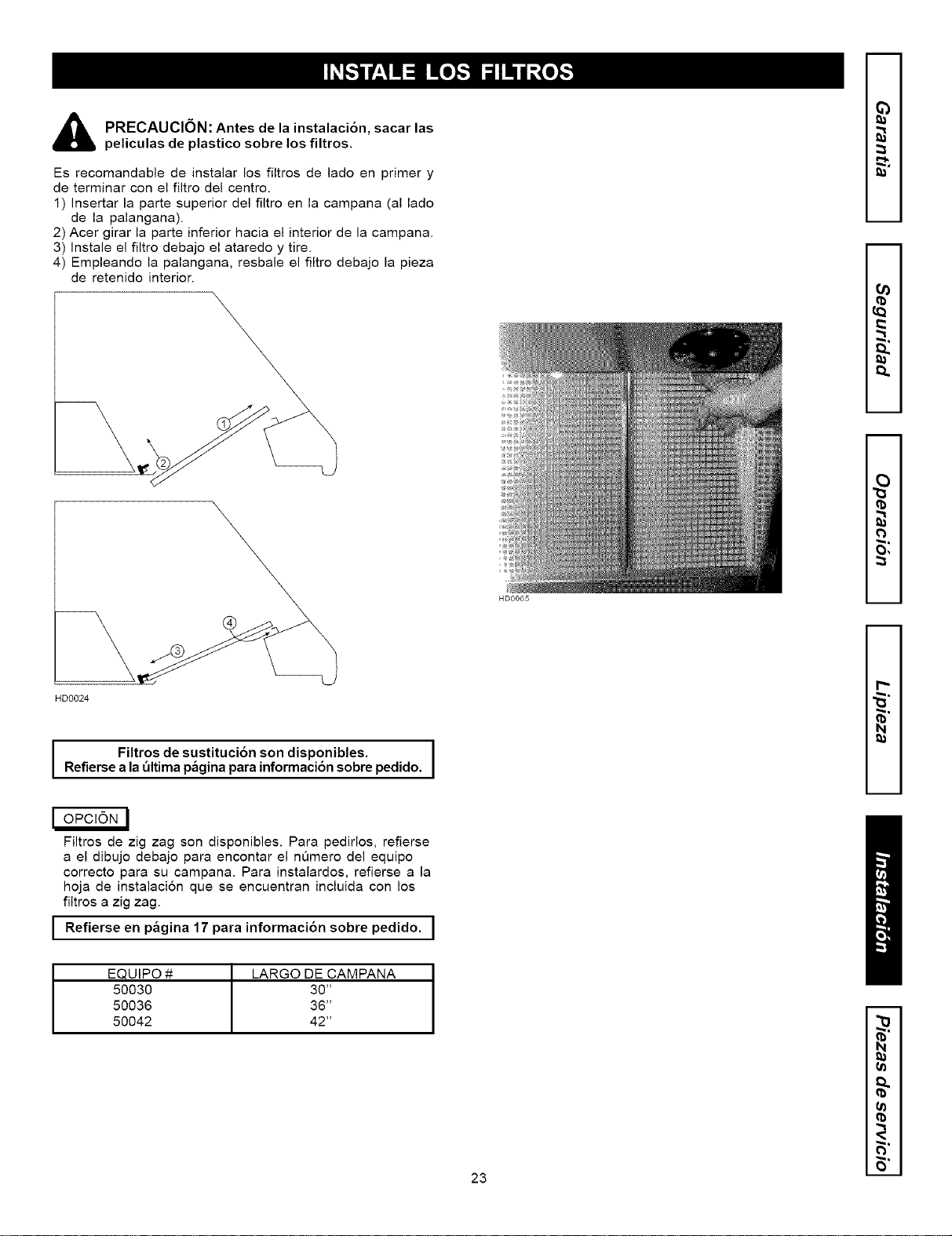
PRECAUCION: Antes de la instalaci6n, sacar las
peliculas de plastico sobre los filtros.
Es recomandable de instalar los filtros de lado en primer y
de terminar con el filtro del centro.
1) Insertar la parte superior del filtro en la campana (al lado
de la palangana).
2) Acer girar la parte inferior hacia el interior de la campana.
3) Instale el filtro debajo el ataredo y tire.
4) Empleando la palangana, resbale el filtro debajo la pieza
de retenido interior.
m
m
m
m
2
O,
m
m
HD0024
Filtros de sustituci6n son disponibles. I
Refierse a la _ltima p_gina para informaci6n sobre pedido.
I
I OPCION l
Filtrosde zig zag son disponibles.Para pedirlos,refierse
a el dibujo debajo para encontar el numero del equipo
correcto para su campana. Para instalardos, refierse a la
hoja de instalacion que se encuentran incluida con los
filtros a zig zag.
I Refierse en p_gina 17 informaci6n sobre pedido. I
para
I
r_
"6"
N
EQUIPO # LARGO DE CAMPANA
50030 30"
50036 36"
50042 42"
23
m
N
F,"
\
18
15
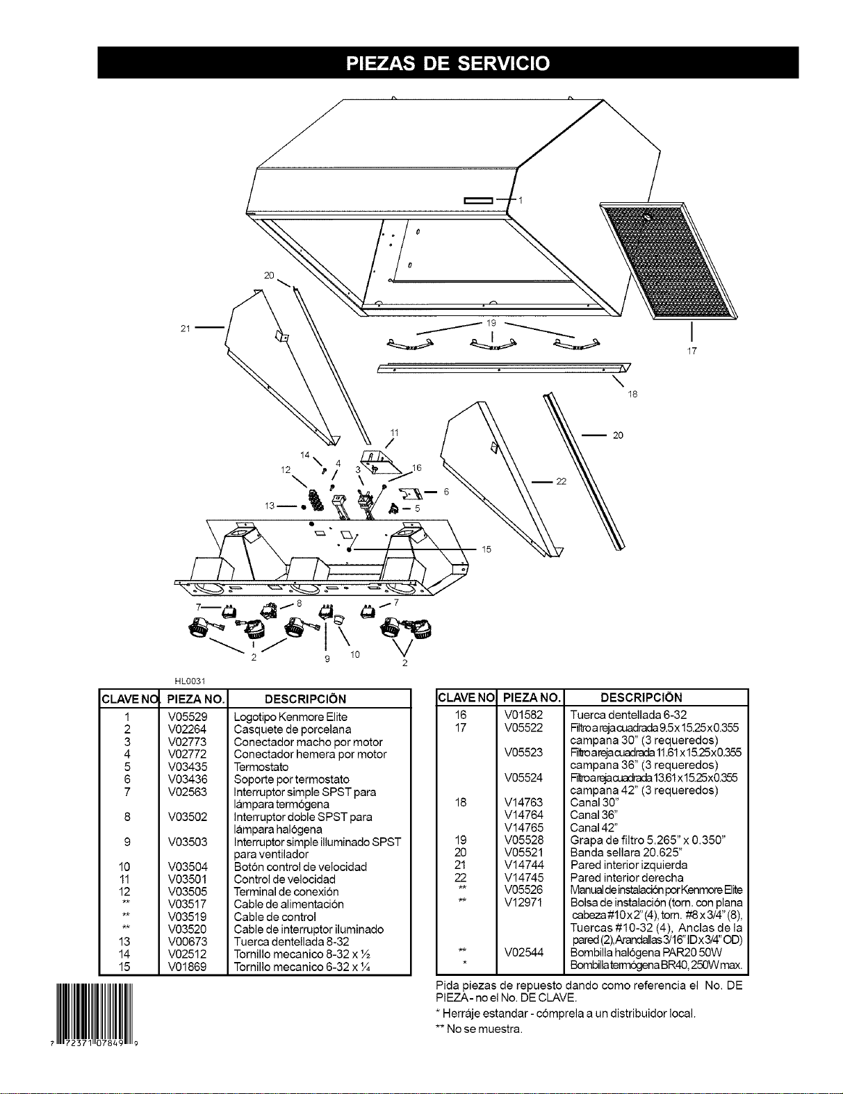
CLAVENC
1
2
3
4
5
6
10
11
12
13
14
15
HLO031
PIEZA NO.
V05529
V02264
V02773
V02772
V03435
V03436
V02563
V03502
V03503
V03504
V03501
V03505
V03517
V03519
V03520
V00673
V02512
V01869
DESCRIPCI()N
Logotipo Kenmore Elite
Casquete de porcelana
Conectador macho por motor
Conectador hemera pot motor
Termostato
Soporte por termostato
Interruptor simple SPST para
lampara term6gena
Interruptor doble SPST para
lampara hal_x:jena
Interruptor simple illuminado SPST
para ventilador
Bot6n control de velocidad
Control de velocidad
Terminal de conexion
Cable de alimentaci6n
Cable de control
Cable de interruptor iluminado
Tuerca dentellada 8-32
Tornillo mecanico 8-32 x ½
Tornillo mecanico 6-32 x %
CLAVE NO
16
17
18
19
20
21
22
PIEZANO.
V01582
V05522
V05523
V05524
V14763
V14764
V14765
V05528
V05521
V14744
V14745
V05526
V12971
V02544
I
17
Pida piezas de repuesto dando como referencia el No. DE
PIEZA- no el No. DE CLAVE.
* Herraje estandar - c6mprela a un distribuidor local.
** No se muestra.
DESCRIPClON
Tuerca dentellada 6-32
Filto a rejacuba 9.5x 15.25x0.355
campana 30" (3 requeredos)
Fireoarejacuadrada 11.61x 15.25x0.355
campana 36" (3 requeredos)
Htroa_acuadrada 13.61xl 525x0.355
campana 42" (3 requeredos)
Canal 30"
Canal 36"
Canal 42"
Grapa de filtro 5.265" x 0.350"
Banda sellara 20.625"
Pared interior izquierda
Pared interior derecha
Manual deinstaladon porKanmore Elite
Bolsa de instalaci6n (torn. con plana
cabeza#10xZ'(4), tom. #8x3/4" (8),
Tuercas #10-32 (4), Anclas de la
pared(2),Arandallas3/16" IDx3/4" OD)
Bombilla hal6gena PAR20 50W
Bombillaterm6gena BR40, 250W max.

