DAIKIN ROOM AIR CONDITIONER
INSTALLATION MANUAL
R410A Split Series
Installation manual
Manuel dinstallation
Manual de instalación
EnglishFrançaisEspañol
MODELS
FDXS09LVJU
FDXS12LVJU
CDXS07LVJU
CDXS15LVJU
CDXS18LVJU
CDXS24LVJU
Manuel dinstallation
00_CV_3P297301-4E.indd 1 5/31/2017 14:04:45
English
■English 1
Safety Precautions
•ReadtheseSafetyPrecautionscarefullytoensurecorrectinstallation.
•ThismanualclassiestheprecautionsintoDANGER,WARNINGandCAUTION.
Besuretofollowalltheprecautionsbelow:theyareallimportantforensuringsafety.
DANGER ..........Indicates an imminently hazardous situation which, if not avoided, will result in death or serious
injury.
WARNING ........Failure to follow any of WARNING is likely to result in such grave consequences as death or serious
injury.
CAUTION .........Failure to follow any of CAUTION may in some cases result in grave consequences.
•Thefollowingsafetysymbolsareusedthroughoutthismanual:
Besuretoobservethisinstruction. Besuretoestablishanearthconnection. Neverattempt.
•Aftercompletinginstallation,testtheunittocheckforinstallationerrors.Givetheuseradequateinstructions
concerningtheuseandcleaningoftheunitaccordingtotheOperationManual.
DANGER
•Refrigerantgasisheavierthanairandreplacesoxygen.Amassiveleakcouldleadtooxygendepletion,especially
inbasements,andanasphyxiationhazardcouldoccurleadingtoseriousinjuryordeath.
•Iftherefrigerantgasleaksduringinstallation,ventilatetheareaimmediately.
Refrigerantgasmayproduceatoxicgasifitcomesincontactwithresuchasfromafanheater,stoveorcookingdevice.Exposuretothisgas
couldcausesevereinjuryordeath.
•Aftercompletingtheinstallationwork,checkthattherefrigerantgasdoesnotleak.
Refrigerantgasmayproduceatoxicgasifitcomesincontactwithresuchasfromafanheater,stoveorcookingdevice.Exposuretothisgas
couldcausesevereinjuryordeath.
•Donotgroundunitstowaterpipes,telephonewiresorlightningrodsbecauseincompletegroundingcouldcausea
severeshockhazardresultinginsevereinjuryordeath,andtogaspipesbecauseagasleakcouldresultinan
explosionwhichcouldleadtosevereinjuryordeath.
•Safelydisposeofthepackingmaterials.
Packingmaterials,suchasnailsandothermetalorwoodenparts,maycausestabsorotherinjuries.Tearapartandthrowawayplastic
packagingbagssothatchildrenwillnotplaywiththem.Childrenplayingwithplasticbagsfacethedangerofdeathbysuffocation.
•Donotinstallunitinanareawhereammablematerialsarepresentduetoriskofexplosionresultinginserious
injuryordeath.
•Donotgroundunitstotelephonewiresorlightningrodsbecauselightningstrikescouldcauseasevereshock
hazardresultinginsevereinjuryordeath,andtogaspipesbecauseagasleakcouldresultinanexplosionwhich
couldleadtosevereinjuryordeath.
WARNING
•Installationshallbelefttotheauthorizeddealeroranothertrainedprofessional.
Improperinstallationmaycausewaterleakage,electricalshock,re,orequipmentdamage.
•Installtheairconditioneraccordingtotheinstructionsgiveninthismanual.
Incompleteinstallationmaycausewaterleakage,electricalshock,reorequipmentdamage.
•Besuretousethesuppliedorexactspeciedinstallationparts.
Useofotherpartsmaycausetheunittocometolose,waterleakage,electricalshock,reorequipmentdamage.
•Installtheairconditioneronasolidbasethatislevelandcansupporttheweightoftheunit.
Aninadequatebaseorincompleteinstallationmaycauseinjuryorequipmentdamageintheeventtheunitfallsoffthebaseorcomesloose.
•Electricalworkshallbecarriedoutinaccordancewiththeinstallationmanualandthenational,stateandlocal
electricalwiringcodes.
Insufcientcapacityorincompleteelectricalworkmaycauseelectricalshock,reorequipmentdamage.
•Besuretouseadedicatedpowercircuit.Neveruseapowersupplysharedbyanotherappliance.
Followallappropriateelectricalcodes.
•Forwiring,useawireorcablelongenoughtocovertheentiredistancewithnosplicesifpossible.Donotusean
extensioncord.Donotputotherloadsonthepowersupply.Useonlyaseparatededicatedpowercircuit.
(Failuretodosomaycauseabnormalheat,electricshock,reorequipmentdamage.)
•Usethespeciedtypesofwiresforelectricalconnectionsbetweentheindoorandoutdoorunits.Followallstate
andlocalelectricalcodes.
Firmlyclamptheinterconnectingwiressotheirterminalsreceivenoexternalstresses.Incompleteconnectionsorclampingmaycauseterminal
overheating,reorequipmentdamage.
01_EN_3P297301-4D.indd 1 5/8/2017 5:10:20 PM
2 ■English
Safety Precautions
WARNING
•Afterconnectingallwiringbesuretoshapethecablessothattheydonotputunduestressontheelectrical
covers,panelsorterminals.
Installcoversoverthewires.Incompletecoverinstallationmaycauseterminaloverheating,electricalshock,reorequipmentdamage.
•Wheninstallingorrelocatingthesystem,besuretokeeptherefrigerantcircuitfreefromallsubstancesotherthan
thespeciedrefrigerant(R410A),suchasair.
(Anypresenceofairorotherforeignsubstanceintherefrigerantcircuitcausesanabnormalpressurerisewhichmayresultinrupture,resulting
ininjury.)
•Duringpump-down,stopthecompressorbeforeremovingtherefrigerantpiping.
Ifthecompressorisstillrunningandtheshut-offvalveisopenduringpump-down,airwillbesuckedinwhentherefrigerantpipingisremoved,
causingabnormallyhighpressurewhichcouldleadtoequipmentdamageorandpersonalinjury.
•Duringinstallation,attachtherefrigerantpipingsecurelybeforerunningthecompressor.
Iftherefrigerantpipesarenotattachedandtheshut-offvalveisopenwhenthecompressorisrun,airwillbesuckedin,causingabnormal
pressureintherefrigerationcycle,whichmayresultinequipmentdamageandeveninjury.
•Installaleakcircuitbreaker,asrequired.
Ifaleakcircuitbreakerisnotinstalled,electricshockmayresult.
•Besuretoinstallagroundfaultcircuitinterrupterbreaker.
Failuretoinstallagroundfaultcircuitinterrupterbreakermayresultinelectricallyshocksorpersonalinjury.
CAUTION
•Establishdrainpipingaccordingtotheinstructionsofthismanual.
Inadequatepipingmaycausewaterdamage.
•Noteforinstallingtheoutdoorunit.(Forheatpumpmodelonly.)
Inregionsofthecountrywheretheoutsidetemperatureisatorbelowthefreezingpoint,thedrainmayfreeze.Ifso,itisrecommendedthatan
electricheaterbeinstalledinordertoprotectthedrainfromfreezing.
•Tightenthearenutaccordingtothespeciedtorque.Atorquewrenchshouldbeused.
Ifthearenutistightenedtoomuch,thearenutmaycrackovertimeandcauserefrigerantleakage.
•Donottouchtheheatexchangerns.
Improperhandlingmayresultininjury.
•Beverycarefulaboutproducttransportation.
SomeproductsusePPbandsforpackaging.DonotuseanyPPbandsforameansoftransportation.Itisdangerous.
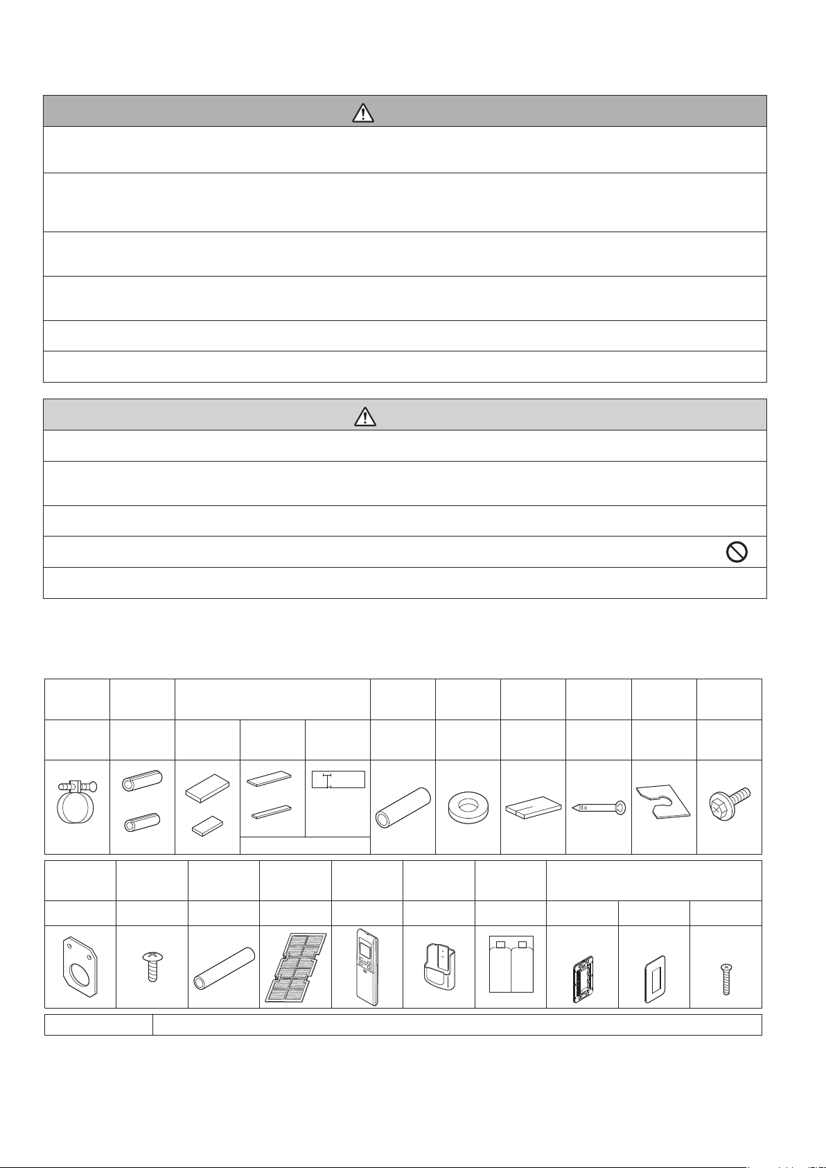
Accessories
Wireless
remote
controller
1 pc.
Screws for
conduit
mounting plate
2 pcs.
Insulation
tube
1 pc.
Dry battery
AAA. LR03
(alkaline)
Mounting
frame
Screws
M4 × 25
Decorative
cover
Remote
controller
holder
1 pc.1 pc. 1 pc.
Receiver kit
Air filter
1 set 1 pc. 2 pcs.
2 pcs.
Clamp
metal
1 pc. 1 pc.
Insulation
for fitting
1 each
Sealing pad
Large and
small
1 each
for gas pipe
for liquid pipe
One is spare
Large
Small
24 pcs.4 pcs.
Washer for
hanger
bracket
8 pcs. 2 pcs. 6 pcs. 1 set
Drain hose
Sealing
material
Clamp
Washer
fixing plate
1 set
Screws for
duct flanges
Stored in outlet vent
1 pc.
Hanger
(right)
insulation
[ Other ] • Operation manual • Installation manual
1 pc.
Conduit
mounting
plate
3 pcs.
(only for
CDXS)
2 large
1 small
01_EN_3P297301-4D.indd 2 5/8/2017 5:10:21 PM
English
■English 3
Choosing an Installation Site
•Beforechoosingtheinstallationsite,obtainuserapproval.
1. Indoor unit
CAUTION
•Whenmovingtheunitduringorafterunpacking,makesuretoliftitbyholdingitsliftinglugs.Donotexertanypressureon
otherparts,especiallytherefrigerantpiping,drainpipingandangeparts.
Wearprotectivegear(suchasgloves)wheninstallingtheunit.
•Ifyouthinkthehumidityinsidetheceilingmightexceed86°F(30°C)andRH80%,reinforcetheinsulationontheunitbody.
Useglasswoolorpolyethylenefoamasinsulationsothatthethicknessismorethan0.4in(10mm)andtsinsidetheceiling
opening.
•Optimumairdistributionisensured.
•Theairpassageisnotblocked.
•Condensatecandrainproperly.
•Theceilingisstrongenoughtobeartheweightoftheindoorunit.
•Afalseceilingdoesnotseemtobeatanincline.
•Sufcientclearanceformaintenanceandservicingisensured.
•Pipingbetweentheindoorandoutdoorunitsiswithintheallowablelimits.
(Refertotheinstallationmanualfortheoutdoorunit.)
•Theindoorunit,outdoorunit,powersupplywiringandtransmissionwiringisat
least3.3ft(1m)awayfromtelevisionsandradios.Thispreventsimage
interferenceandnoiseinelectricalappliances.(Noisemaybegenerated
dependingontheconditionsunderwhichtheelectricwaveisgenerated,even
ifa3.3ft(1m)allowanceismaintained.)
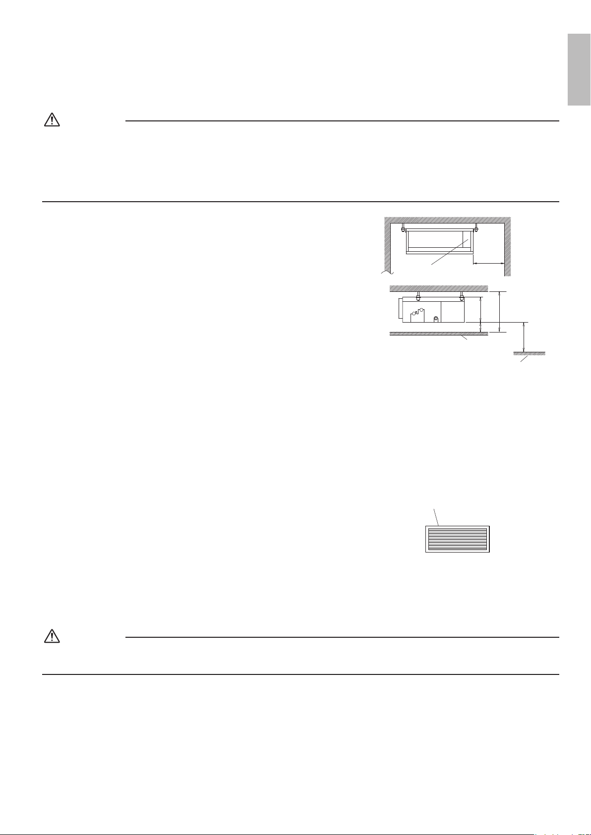
■
Use suspension bolts to install the unit. Check whether or not the
ceiling is strong enough to support the weight of the unit. If there is
a risk that the ceiling is not strong enough, reinforce the ceiling
before installing the unit.
(Installationpitchismarkedonthecartonboxforinstallation.Refertoittocheck
forpointsrequiringreinforcing.)Selectthe*Hdimensionsuchthatadownward
slopeofatleast1/100isensuredasindicatedin“Drain Piping Work”.
•Theinstallationpitchislistedonthepackingmaterial,andshouldbechecked
whendecidingwhethertoreinforcethelocationornot.
Control box
Maintenance
space
12 (300)
or more
13/16 (20) or more
100 (2500)
or more
*H=
9-1/2 (240)
or more
7-7/8
(200)
Ceiling
Floor surface
(unit : in (mm))
If there is
no ceiling
■
Select the signal receiver mounting location according to the
following conditions:
•Installthesignalreceiver,whichhasabuilt-intemperaturesensor,nearthe
intakeventwherethereisconvectionofairanditcangetanaccuratereading
oftheroom’stemperature.Iftheintakeventisinanotherroomortheunit
cannotbeinstalledneartheintakeventforanyotherreason,installit5ft
(1.5m)abovetheooronawallwherethereisconvection.
•Inordertogetanaccuratereadingoftheroom’stemperature,installthesignal
receiverinalocationwhereitisnotexposeddirectlytocoldorhotairfromthe
airdischargegrilleortodirectsunlight.
•Sincethereceiverhasabuilt-inlightreceptortoreceivesignalsfromthe
wirelessremotecontroller,donotmountitinalocationwherethesignalmay
beblockedbyacurtain,etc.
Air outlet grille:
Wooden or plastic grille is recommended
because condensation may occur
depending on humidity conditions.
CAUTION
Ifthesignalreceiverisnotinstalledinalocationwherethereisconvectionofair,itmaybeunabletogetanaccuratereading
oftheroom’stemperature.
01_EN_3P297301-4D.indd 3 5/8/2017 5:10:21 PM
4 ■English
Choosing an Installation Site
2. Wireless remote controller
•Turnonalltheuorescentlampsintheroom,ifany,andndthesitewhereremotecontrollersignalsareproperly
receivedbytheindoorunit(within13ft(4m)).
3. Outdoor unit
•Foroutdoorunitinstallation,seetheinstallationmanualsuppliedwiththeoutdoorunit.
Preparations before Installation
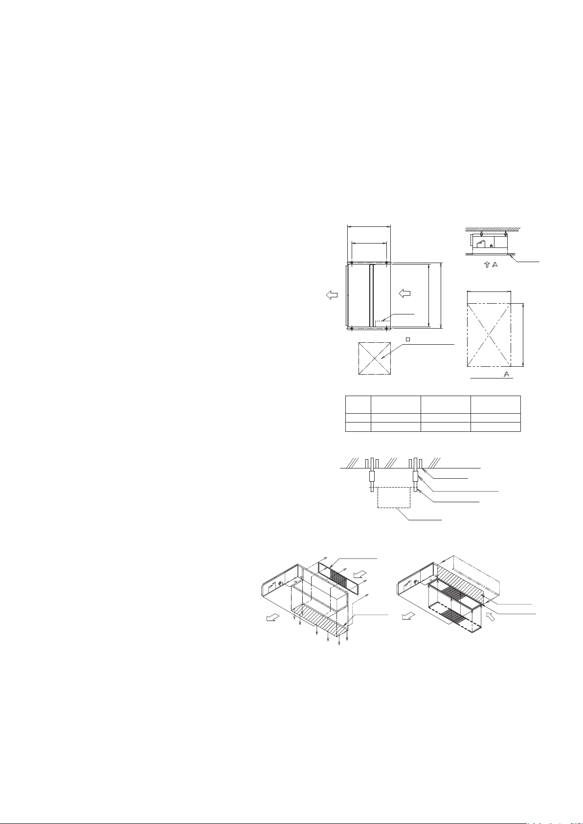
■
Relation of the unit to the suspension bolt positions.
•Installtheinspectionopeningonthecontrolboxsidewhere
maintenanceandinspectionofthecontrolboxareeasy.Install
theinspectionopeningalsointhelowerpartoftheunit.
■
Make sure the range of the unit’s external static
pressure is not exceeded.
(Seethetechnicaldocumentationfortherangeoftheexternal
staticpressuresetting.)
■
Open the installation hole. (Pre-set ceilings)
•Oncetheinstallationholeisopenedintheceilingwheretheunit
istobeinstalled,passrefrigerantpiping,drainpiping,
transmissionwiring,andremotecontrollerwiring(unneededif
usingawirelessremotecontroller)totheunit’spipingandwiring
holes.See“Refrigerant Piping Work”,“Drain Piping Work”,
and“Wiring”.
•Afteropeningtheceilinghole,makesureceilingislevelif
needed.Itmightbenecessarytoreinforcetheceilingframeto
preventshaking.Consultanarchitectorcarpenterfordetails.
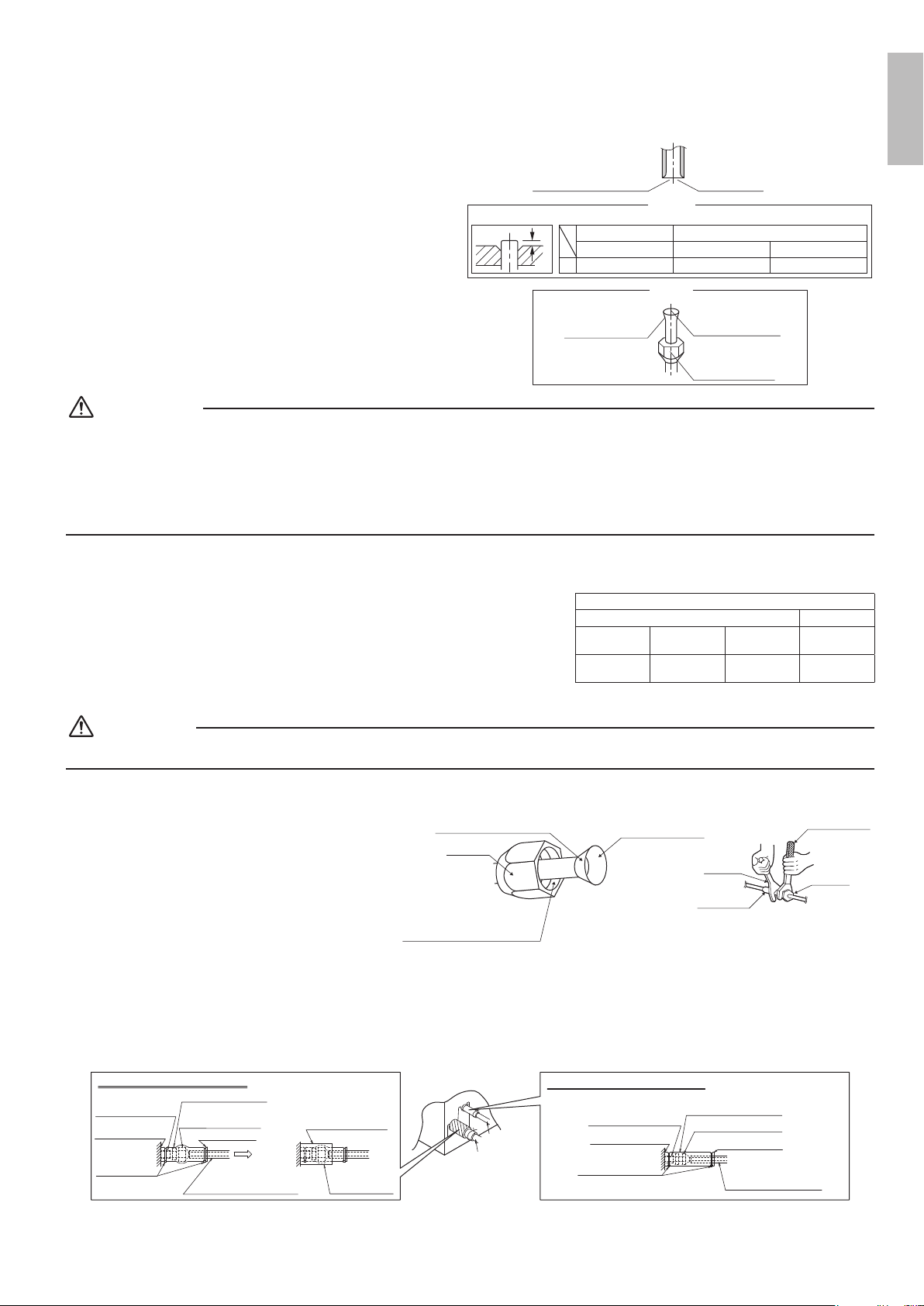
■
Install the suspension bolts.
(UseW3/8toM10suspensionbolts.)
•Useahole-in-anchor,sunkeninsert,sunkenanchorforexisting
ceilings,andasunkeninsert,sunkenanchororotherparttobe
procuredintheeldtoreinforcetheceilingtobearingtheweight
oftheunit.(RefertoFig.)
19-11/16 (500)
17-3/4 (450)
(Inspection opening
size)
Air outlet
Suspension
bolt pitch
(unit : in (mm))
Air inlet
Control
box
(Suspension bolt pitch)
Ceiling
24-7/16 (620)
24-7/16 (620)
A
Arrow view
Inspection door
(Ceiling opening)
<SERVICE SPACE>
A
B
FDXS09/12
CDXS07
CDXS15/18
A
27-9/16 (700)
B
29-1/8 (740) 37 (940)
35-7/16 (900)
CDXS24
44-7/8 (1140)
43-5/16 (1000)
Note: All the above parts are field supplied.
Suspension bolt
Long nut or turn-buckle
Anchor bolt
Indoor unit
Ceiling slab
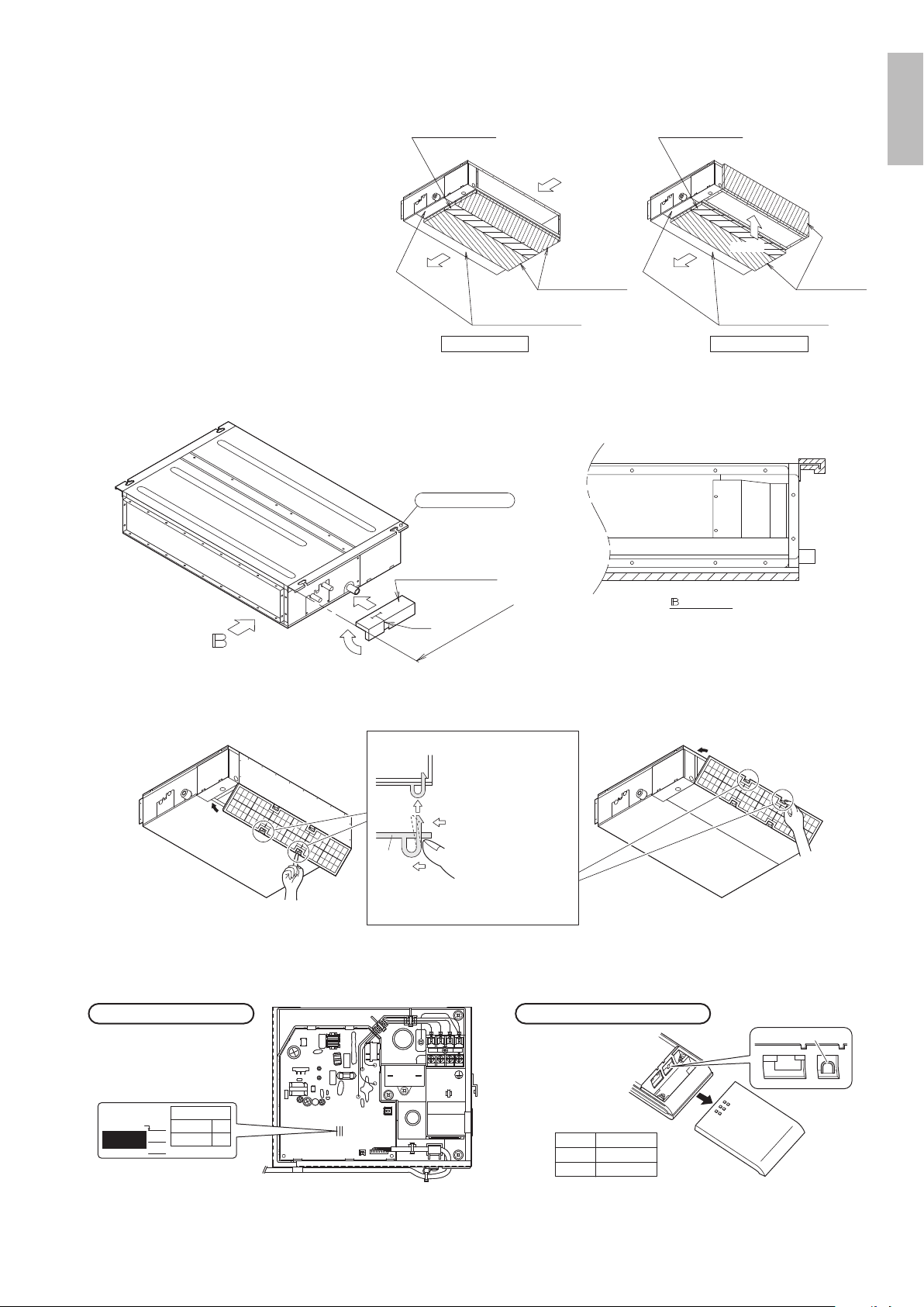
■
Mount chamber cover and air lter
(accessory).
Forbottomintake,replacethechambercoverandthe
protectionnetintheprocedurelistedinFig.
(1)Removetheprotectionnet.(6locations)
Removethechambercover.(7locations)
(2)Reattachtheremovedchambercoverinthe
orientationshowninFig.(7locations)
Reattachtheremovedprotectionnetinthe
orientationshowninFig.(6locations)
RefertoFig.forthedirectionoftheprotectionnet.
Air inlet
Air inlet
(1)
Chamber
cover
(2)
Air outlet
Air outlet
Chamber
cover
Protection net
Protection net
01_EN_3P297301-4D.indd 4 5/8/2017 5:10:21 PM
English
■English 5
(3)Attachsealingpadasshownintheright
gure.(Storedinoutletvent)(onlyfor
CDXS)
(Inordertotakeintheairinsidethe
ceiling,andwhennottakinginairfrom
outdoorair,itisnotnecessarytostick.)
•Attachthesealingpad(accessory)to
theplatemetalsectionswhicharenot
coveredbyanti-sweatmaterial.
•Makesuretherearenogapsbetween
thedifferentpiecesofsealingpad.
Air inlet
(3)
Air outlet Air outlet
Air inlet
Anti-sweat material
included with the product
Anti-sweat material
included with the product
Sealing pad (Small)
For rear intake type
Sealing pad (Large)
Sealing pad (Small)
(accessory) (accessory)
Sealing pad
(Large)
(accessory) (accessory)
For bottom intake type
(4)Attachthehanger(right)insulationtotherighthanger.(Storedinoutletvent)
(Seethebelowgureforthestickingbaseline.)
Hanger (right) insulation
(accessory)
Slit
Sticking base line
Hanger bracket (right)
Arrow view
(5)Attachtheairlter(accessory)inthemannershowninthediagram.
In case of bottom side
In case of back side
Filter
Push
Push
Main unit
Attach the filter to
the main unit while
pushing down on
the bends. *
*
FDXS09/12, CDXS07/15/18 : 2 bends
CDXS24 : 3 bends
■
When two indoor units are installed in one room, one of the two wireless remote controllers can be easily
set for another addresses.
J4 ADDRESS
EXIST 1
CUT 2
PCB in the indoor unit
• Cut the jumper
JA on PCB.
• Cut the jumper J4.
Wireless remote controller
1 2 3
JA
ADDRESS:
CUT
EXIST
1
2
ADDRESS
JA
JB
JC
J4
01_EN_3P297301-4D.indd 5 5/8/2017 5:10:22 PM
6 ■English
Indoor Unit Installation
<< As for the parts to be used for installation work, be sure to use the provided accessories and specied
parts designated by our company. >>
■
Install the indoor unit temporarily.
•Attachthehangerbrackettothesuspensionbolt.
Besuretoxitsecurelybyusinganutandwasher
fromtheupperandlowersidesofthehanger
bracket.(RefertoFig.)
[ PRECAUTION ]
Sincetheunitusesaplasticdrainpan,prevent
weldingspatterandotherforeignsubstancesfrom
enteringtheoutletholeduringinstallation.
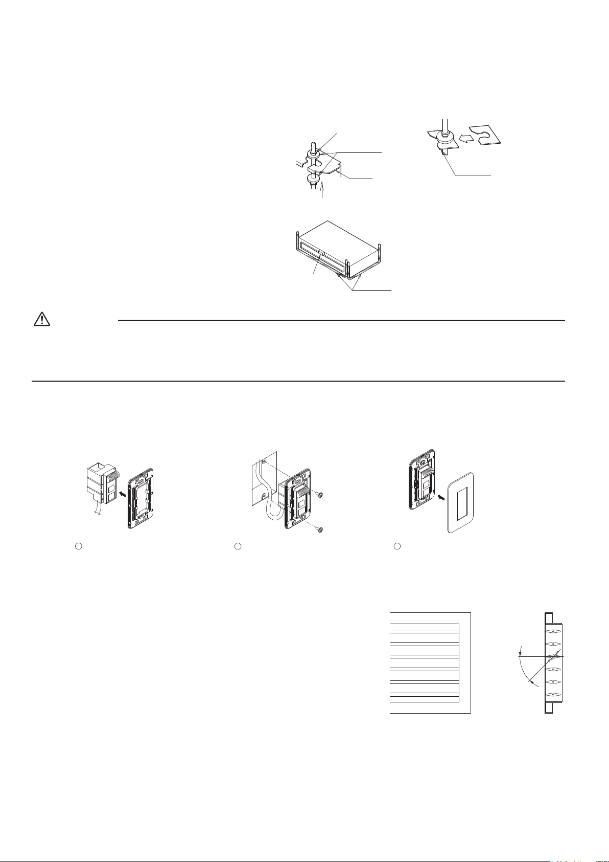
■
Adjust the height of the unit.
■
Check the unit is horizontally level.
[ How to secure washers ]
Insert
below washer
Washer
fixing plate
(accessory)
Part to be procured
in the field
[ Securing the hanger bracket ]
Washer for
hanging bracket
Hanger
bracket
Tighten
(double nut)
(accessory)
Vinyl tube
Level
CAUTION
•Makesuretheunitisinstalledlevelusingaleveloraplastictubelledwithwater.Inusingaplastictubeinsteadofalevel,
adjustthetopsurfaceoftheunittothesurfaceofthewateratbothendsoftheplastictubeandadjusttheunithorizontally.
(Onethingtowatchoutforinparticularisifitisinstalledsothattheslopeisnotinthedirectionofthedrainpiping,asthis
mightcauseleaking.)
■
Tighten the upper nut.
■
Mounting the receiver.
Mountthereceiverasshownbelow.
1
Press the receiver into the
mounting frame.
2
Mount the completed
assembly using two screws.
3
Press the decorative cover into
the mounting frame.
Note) Mount the Remote controller cord far enough away from strong electrical wires (such as distribution wires for
electrical lights, air conditioners, etc.) and from weak electrical wires (such as wires for telephones, intercoms, etc.).
For heat pump: If your feet feel cold when using the heating function, it is
recommended that the air outlet grille shown at below be attached.
(Adjustable angle)
45°
Outdoor unit Installation
Installasdescribedintheinstallationmanualsuppliedwiththeoutdoorunit.
01_EN_3P297301-4D.indd 6 5/8/2017 5:10:23 PM
English
■English 7
Refrigerant Piping Work
Seetheinstallationmanualsuppliedwiththeoutdoorunit.
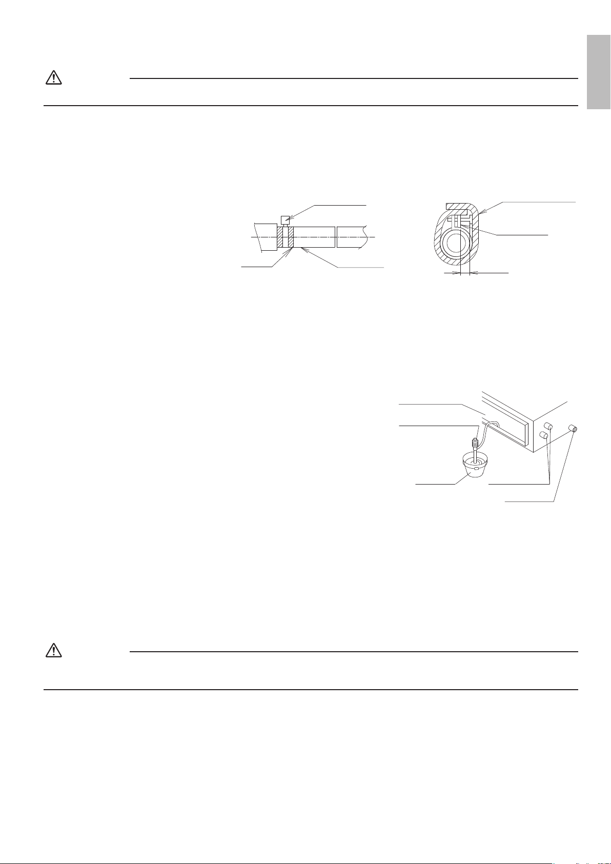
1. Flaring the pipe end
1)Cutthepipeendwithapipecutter.
2)Removeburrswiththecutsurfacefacing
downwardsothatthechipsdonotenterthepipe.
3)Putthearenutonthepipe.
4)Flarethepipe.
5)Checkthatthearingisproperlymade.
A
A
(Cut exactly at right angles.) Remove burrs
Flare’s inner surface
must be flaw-free.
The pipe end must
be evenly flared in a
perfect circle.
Make sure that the
flare nut is fitted.
Check
0-0.02in (0-0.5mm)
0.04-0.06in (1.0-1.5mm) 0.06-0.08in (1.5-2.0mm)
Set exactly at the position shown below.
Clutch-type
Flare tool for R410A
Clutch-type (Rigid-type)
Wing-nut type (Imperial-type)
Conventional flare tool
Flaring
Die
WARNING
•Donotusemineraloilonaredpart.
•Preventmineraloilfromgettingintothesystemasthiswouldreducethelifetimeoftheunits.
•Neverusepipingwhichhasbeenusedforpreviousinstallations.Onlyusepartswhicharedeliveredwiththeunit.
•NeverinstalladriertothisR410Aunitinordertoguaranteeitslifetime.
•Thedryingmaterialmaydissolveanddamagethesystem.
Incompletearingmaycauserefrigerantgasleakage.
2. Refrigerant piping
1)Topreventgasleakage,applyrefrigerationmachineoiltotheinner
surfaceoftheare.(UserefrigerationoilforR410A)
2)Alignthecentersofbotharesandtightenthearenuts3or4turns
byhand.Thentightenthemfullywiththetorquewrenches.
•Usetorquewrencheswhentighteningthearenutstoprevent
damagetothearenutsandescapinggas.
Flarenuttighteningtorque
Gasside Liquidside
3/8inch
(9.5mm)
1/2inch
(12.7mm)
5/8inch
(15.9mm)
1/4inch
(6.4mm)
24.1-29.4ft•lbf
(32.7-39.9N•m)
36.5-44.5ft•lbf
(49.5-60.3N•m)
45.6-55.6ft•lbf
(61.8-75.4N•m)
10.4-12.7ft•lbf
(14.2-17.2N•m)
CAUTION
•Overtightening may damage the are and cause leaks.
3) After the work is nished, make sure to
check that there is no gas leak.
Torque wrench
Piping union
Flare nut
Spanner
Do not apply refrigeration
oil to the outer surface.
Flare nut
Apply refrigeration
oil to the inner
surface of the flare.
Do not apply refrigeration oil to
the flare nut to avoid tightening
with excessive torque.
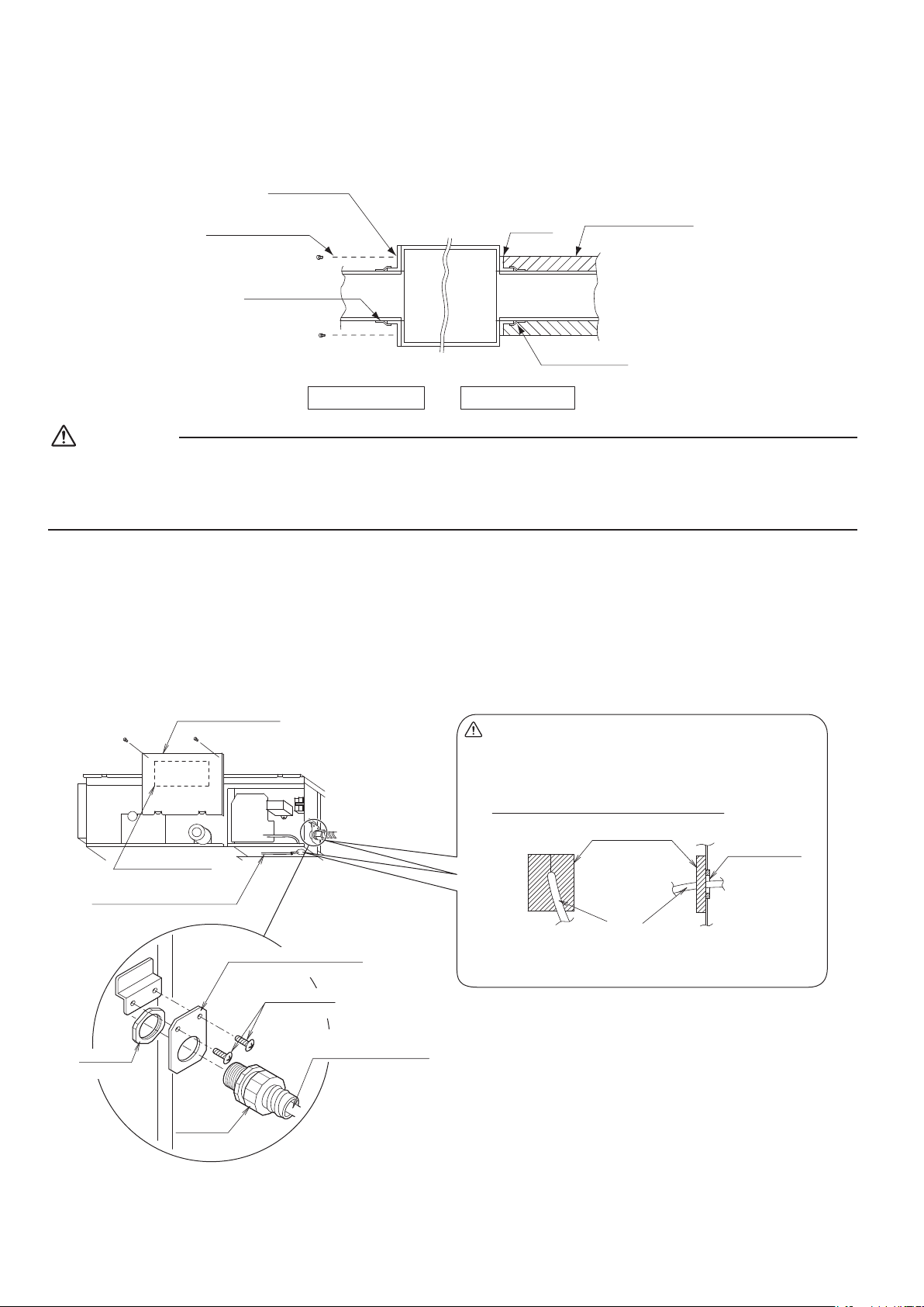
4) After checking for gas leaks, be sure to insulate the pipe connections.
•Insulateusingtheinsulationforttingincludedwiththeliquidandgaspipes.Besides,makesuretheinsulationfortting
ontheliquidandgaspipinghasitsseamsfacingup.
(Tightenbothedgeswithclamp.)
•Forthegaspiping,wrapthemediumsealingpadovertheinsulationfortting(arenutpart).
Gas pipe
Liquid pipe
Piping insulation
material (main unit)
Attach to base
Flare nut connection
Turn seams up
Insulation for fitting
(accessory)
Clamp
Piping insulation material
(Field supplied)
Gas Piping Insulation Procedure
(accessory)
Main unit
Clamp (accessory)
Flare nut connection
Turn seams up
Piping insulation material
(Field supplied)
Piping insulation
material (main unit)
Attach to base
Main unit
Insulation for fitting
(accessory)
Liquid Piping Insulation Procedure
Small sealing pad
Measure the length of the gas
pipe as you will have to cover
it with the sealing tape.
(accessory)
Wrap the sealing
tape around the
gas pipe.
Main unit
01_EN_3P297301-4D.indd 7 5/8/2017 5:10:23 PM
8 ■English
Refrigerant Piping Work
CAUTION
Besuretoinsulateanyeldpipingallthewaytothepipingconnectioninsidetheunit.Anyexposedpipingmaycause
condensationorburnsiftouched.
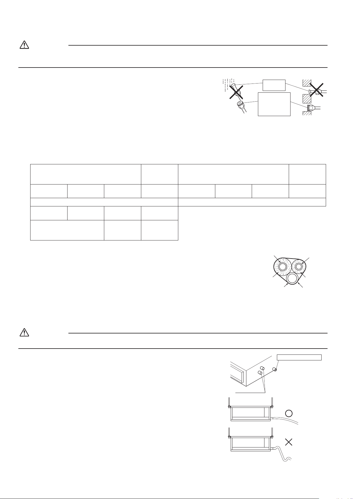
Cautions on Pipe Handling
•Protecttheopenendofthepipeagainstdustandmoisture.
(Tightenbothedgeswithclamp.)
•
Allpipebendsshouldbeasgentleaspossible.Useapipebenderforbending.
(Seetheminimumbendradiusinthetablebelow.)
Wall
If no flare cap is
available, cover
the flare mouth
with tape to keep
dirt or water out.
Be sure to
place a cap.
Rain
Selection of Copper and Heat Insulation materials
Whenusingcommercialcopperpipesandttings,observethefollowing:
•Insulationmaterial:Polyethylenefoam
Heattransferrate:0.041to0.052W/mK(0.024to0.030Btu/fth°F(0.035to0.045kcal/mh°C))
BesuretouseinsulationthatisdesignedforusewithHVACSystems.
•Besuretoinsulateboththegasandliquidpipingandtoprovideinsulationdimensionsasbelow.
Gasside Liquidside Gaspipethermalinsulation
Liquidpipe
thermal
insulation
O.D.3/8inch
(9.5mm)
O.D.1/2inch
(12.7mm)
O.D.5/8inch
(15.9mm)
O.D.1/4inch
(6.4mm)
I.D.15/32-19/32
inch(12-15mm)
I.D.9/16-5/8
inch(14-16mm)
I.D.5/8-25/32
inch(16-20mm)
I.D.5/16-13/32
inch(8-10mm)
Minimumbendradius Thickness13/32inch(10mm)Min.
1-3/16inch
(30mm)ormore
1-9/16inch
(40mm)ormore
1-15/16inch
(50mm)ormore
1-3/16inch
(30mm)ormore
Thickness0.031inch(0.8mm)
(C1220T-O)
Thickness0.039
inch(1.0mm)
(C1220T-O)
Thickness0.031
inch(0.8mm)
(C1220T-O)
Also,whensubjecttohighhumidity,heatinsulationoftherefrigerantpiping(theunitpipingand
branchpiping)mustbefurtherreinforced.
Reinforcetheinsulationwheninstallingtheunitnearbathrooms,kitchens,andothersimilarlocations.
Refertothefollowing:
•86°F(30°C),morethan75%RH:13/16inch(20mm)Min.inthickness
Iftheinsulationisnotsufcient,condensationmayformonthesurfaceoftheinsulation.
•Useseparatethermalinsulationpipesforgasandliquidrefrigerantpipes.
Gas pipe
Liquid pipe
Gas pipe
insulation
Liquid pipe
insulation
Finishing tape
Drain hose
Drain Piping Work
CAUTION
Makesureallwaterisoutbeforemakingtheductconnection.
■
Install the drain piping.
•Makesurethedrainworksproperly.
•Thediameterofthedrainpipeshouldbegreaterthanorequaltothediameterof
theconnectingpipe(vinyltube;pipesize:25/32inch(20mm);outerdimension:
1-1/32inch(26mm)).
Drain pipe connection hole
Refrigerant pipes
Connect the drain pipe after
removing the rubber cap and
insulation tubing attached to
the connection hole.
•Keepthedrainpipeshortandslopingdownwardsatagradientofatleast1/100
topreventairpocketsfromforming.
OK
Wrong
01_EN_3P297301-4D.indd 8 5/8/2017 5:10:24 PM
English
■English 9
CAUTION
•Water accumulating in the drain piping can cause the drain to clog.
•Tokeepthedraintubefromsagging,spacehangingwiresevery3(1)to5ft(1.5m).
•Usethedrainhoseandthemetalclamp.Insertthedrainhosefullyintothedrainsocketandrmlytightenthemetalclampwith
theupperpartofthetapeonthehoseend.Tightenthemetalclampuntilthescrewheadislessthan1/8inch(4mm)fromthe
hose.
•Thetwoareasbelowshouldbeinsulatedbecausecondensationmayformtherecausingwatertoleak.
•Drainpipingpassingindoors
•Drainsockets
Referringthegurebelow,insulatethe
metalclampanddrainhoseusingthe
includedlargesealingpad.
ϕ1/8 inch (4mm)
Large sealing pad
Clamp metal
(accessory)
(accessory)
Clamp metal
Drain hose
Tape
(accessory)
(accessory)
<PRECAUTIONS>
Drainpipingconnections
•Donotconnectthedrainpipingdirectlytosewagepipesthatsmellofammonia.Theammoniainthesewagemightenterthe
indoorunitthroughthedrainpipesandcorrodetheheatexchanger.
•Donottwistorbendthedrainhose,sothatexcessiveforceisnotappliedtoit.
(Thistypeoftreatmentmaycauseleaking.)
■
After piping work is nished, check drainage ows smoothly.
•Graduallyinsertapproximately1Lofwaterintothedrainpantocheck
drainageinthemannerdescribedbelow.
•Graduallypourapproximately1Lofwaterfromtheoutletholeintothe
drainpantocheckdrainage.
•Checkthedrainage.
Portable pump
Refrigerant pipes
Bucket
Air outlet
Drain outlet
Installing the Duct
Connecttheductsuppliedintheeld.
Air inlet side
•Attachtheductandintake-sideange(eldsupply).
•Connecttheangetothemainunitwithaccessoryscrews(in16,20or24positions).
•Wraptheintake-sideangeandductconnectionareawithaluminumtapeorsomethingsimilartopreventairescaping.
CAUTION
•Whenattachingaducttotheintakeside,besurealsotoattachanairlterinsidetheairpassageontheintakeside.(Usean
airlterwhosedustcollectingefciencyisatleast50%inagravimetrictechnique.)
01_EN_3P297301-4D.indd 9 5/8/2017 5:10:24 PM
10 ■English
Installing the Duct
Outlet side
•Connecttheductaccordingtotheinsideoftheoutlet-sideange.
•Wraptheoutlet-sideangeandtheductconnectionareawithaluminumtapeorsomethingsimilartopreventairescaping.
Main unit
Air inlet side
Outlet side
Connection screw
(accessory)
(field supply)
(field supply)
(field supply)
(field supply)
Flange
Flange
Aluminum tape
Aluminum tape
Insulation material
CAUTION
•Besuretoinsulatetheducttopreventcondensationfromforming.(Material:glasswoolorpolyethylenefoam,1inch(25mm)
thick)
•Useelectricinsulationbetweentheductandthewallwhenusingmetalductstopassmetallathsofthenetorfenceshapeor
metalplatingintowoodenbuildings.
Wiring
Seetheinstallationmanualsuppliedwiththeoutdoorunit.
■
HOW TO CONNECT WIRINGS.
•WireonlyafterremovingthecontrolboxcoverasshownintheFig.
*Remote controller wiring
Control box cover
Wiring Diagram
(rear)
Conduit mounting plate
(accessory)
Conduit
(field supply)
Lock nut
(field supply)
Screw
(accessory)
Power supply wiring
Ground wire
• Wrap the power supply wiring and the remote controller
wiring with the sealing material as shown in the figure
below.
(Otherwise, moisture or small creatures such as insects from
the outside may cause short-circuit inside the control box.)
Attach securely so that there are no gaps.
Inside
unit
Outside
unit
[How to adhere it]
Wire
(accessory)
Sealing material
Wiring
through hole
01_EN_3P297301-4D.indd 10 5/8/2017 5:10:24 PM
English
■English 11
CAUTION
•Whendoingthewiring,makesurethewiringisneatanddoesnotcausethecontrolboxcovertostickup,thenclosethecover
rmly.Whenattachingthecontrolboxcover,makesureyoudonotpinchanywires.
•Outsidetheunit,separatethelowvoltagewiring(remotecontrollerwiring)andhighvoltagewiring(groundwireandpower
supplywiring)atleast5insothattheydonotpassthroughthesameplacetogether.Proximitymaycauseelectrical
interference,malfunctions,andbreakage.
[ PRECAUTION ]
•Seealsothe“ElectricalWiringDiagramLabel”whenwiringtheunitforpowersupply.
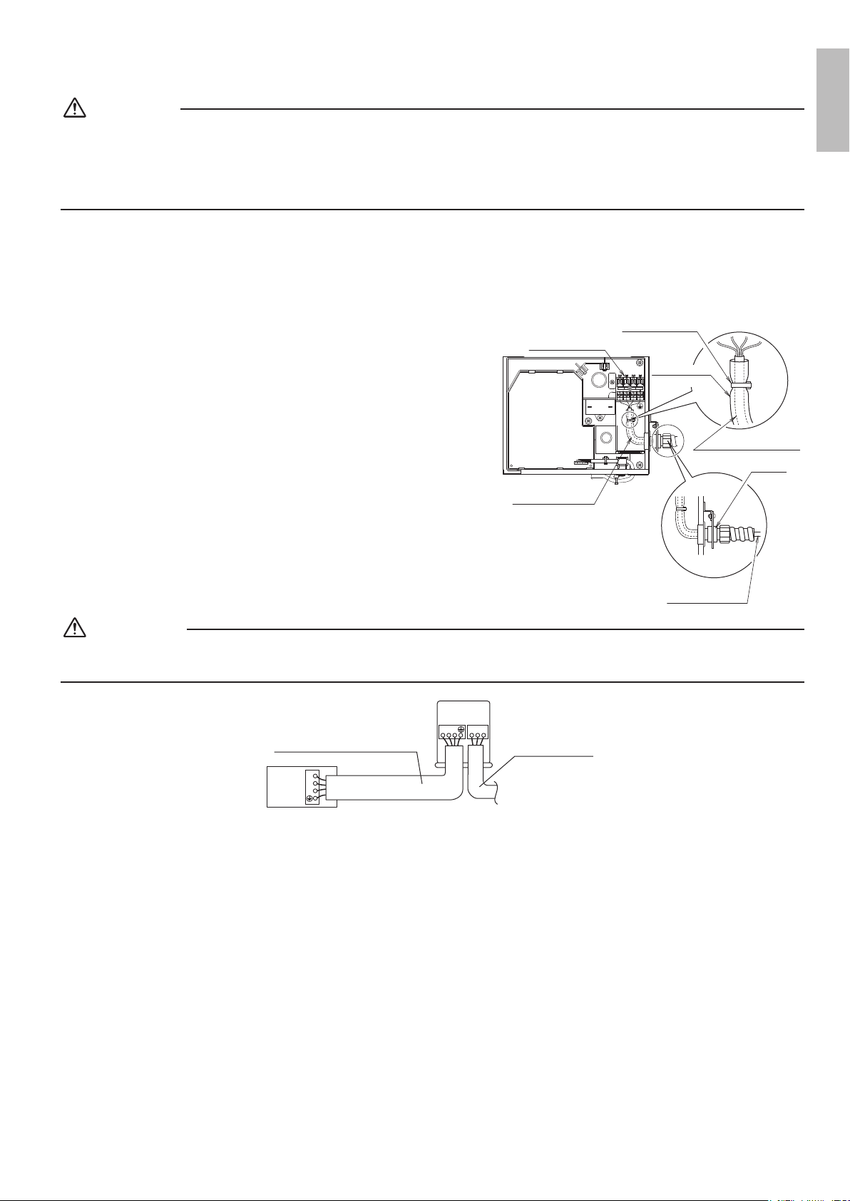
[ Connecting electrical wiring ]
•Power supply wiring and ground wire
Removethecontrolboxcover.
Next,pullthewiresintotheunitthroughtheconduitandthreadthem
throughtheinsulationtube(accessory),thenconnecttothepower
wiringterminalblock(4P).
Securethewirescoveredbytheinsulationtubewiththeclamp
(accessory).
Besuretoputthepartofthesheathedvinylintothecontrolbox.
Terminal block (4P)
Conduit
Power supply wiring
Ground wire
Indoor PC board
(ASSY)
Clamp
(for fixing in place)
(accessory)
Power supply wiring
Ground wire
Power supply wiring
Ground wire
Insulation tube
(accessory)
WARNING
•Do not use tapped wires, stranded wires, extension cords, or starburst connections, as they may cause overheating,
electrical shock, or re.
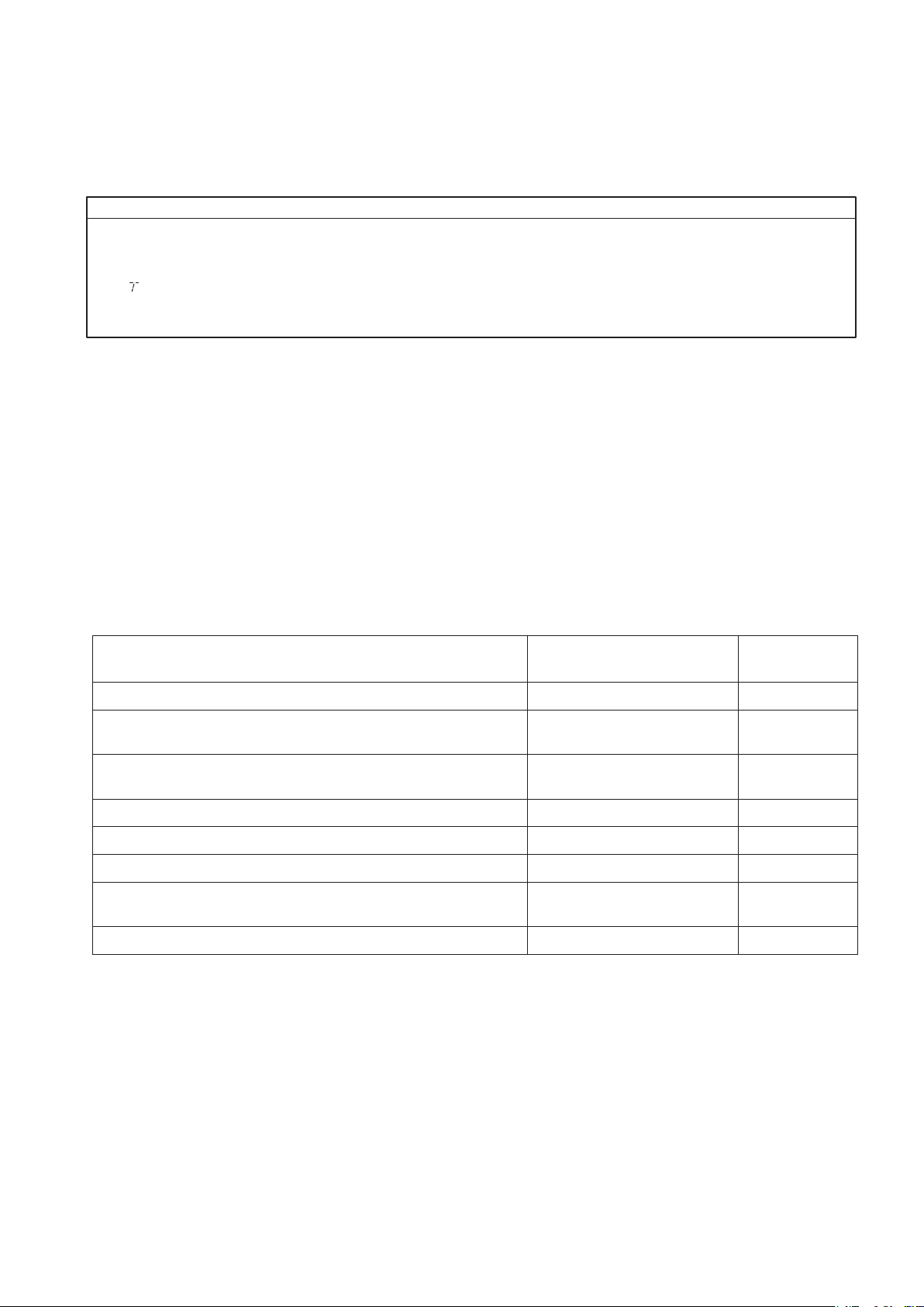
1
2
3
1 2 3
GR
L1L2
Use AWG16 if the connection wire
length is less than 32.8ft (10m), or
AWG14 if it is 32.8ft (10m) or more.
Outdoor unit
Indoor
unit
Use AWG 14 wires.
01_EN_3P297301-4D.indd 11 5/8/2017 5:10:25 PM
12 ■English
Trial Operation and Testing
1. Trial operation and testing
(1)Measurethesupplyvoltageandmakesurethatitfallsinthespeciedrange.
(2)Trialoperationshouldbecarriedoutineithercoolingorheatingmode.
(1) Press ON/OFF button to turn on the system.
(2) Simultaneously press center of TEMP button and MODE button.
(3) Press MODE button twice.
(“ ” will appear on the display to indicate that Trial Operation mode is selected.)
(4) Trial operation mode terminates in approx. 30 minutes and switches into normal mode. To quit the trial operation, press
ON/OFF button.
Trial operation from remote controller
Incoolingmode,selectthelowestprogrammabletemperature;inheatingmode,selectthehighestprogrammable
temperature.
•Trialoperationmaybedisabledineithermodedependingontheroomtemperature.
•Aftertrialoperationiscomplete,setthetemperaturetoanormallevel(79°F(26°C)to82°F(28°C)incoolingmode,68°F
(20°C)to75°F(24°C)inheatingmode).
•Forprotection,thesystemdisablesrestartoperationfor3minutesafteritisturnedoff.
(3)CarryoutthetestoperationinaccordancewiththeOperationManualtoensurethatallfunctionsandparts,areworking
properly.
*Theairconditionerrequiresasmallamountofpowerinitsstandbymode.Ifthesystemisnottobeusedforsometime
afterinstallation,shutoffthecircuitbreakertoeliminateunnecessarypowerconsumption.
*Ifthecircuitbreakertripstoshutoffthepowertotheairconditioner,thesystemwillrestoretheoriginaloperationmode
whenthecircuitbreakeristurnedonagain.
2. Test items
Testitems
Symptom
(diagnosticdisplayonRC)
Check
Indoorandoutdoorunitsareinstalledproperlyonsolidbases. Fall,vibration,noise
Norefrigerantgasleaks.
Incompletecooling/heating
function
Refrigerantgasandliquidpipesandindoordrainhoseextension
arethermallyinsulated.
Waterleakage
Drainpipeisproperlyinstalled. Waterleakage
Systemisproperlygrounded. Electricalleakage
Thespeciedwiresareusedforinterconnectingwireconnections. Inoperativeorburndamage
Indoororoutdoorunit’sairinletordischargehasclearpathofair.
Shut-offvalvesareopened.
Incompletecooling/heating
function
Indoorunitproperlyreceivesremotecontrollercommands. Inoperative
01_EN_3P297301-4D.indd 12 5/8/2017 5:10:25 PM

The two-dimensional bar code is
a manufacturing code.
3P297301-4E
M17B031
(1706)
HT
00_CV_3P297301-4E.indd 2 5/31/2017 14:04:46