

225B
225Bx_s Rl s
Operator's manual
Read the operator's manual carefully and
make sure that you understand the contents
before using the blower.
114 O0 25-95

CONTENTS
Introduction ......................................... 3
Key to symbols .................................... 4
Safety instructions .............................. 5
Description .......................................... 7
Fuel handling ..................................... 12
Start and stop .................................... 14
Using the blower ............................... 16
Maintenance ...................................... 20
Technical data .................................... 25
WARNING
The engine exhaust from this product
contains chemicals known to the State
of Califl_rnia to cause cancer, birth
defects or other reproductive harm.
Maintenance, replacement, or repair of the emission
control devices and systems may be performed by any
nonroad engine repair establishment or individual.
2- English
INTRODUCTION
Husqvarna AB has a policy of continuous product
development and therefore reserves the right to
modify the design and appearance of products
without prior notice.
This operator's manual describes in detail how to
use and service the blower and how to carry out
regular maintenance. It also describes which meas-
ures should be taken to achieve maximum safety
while operating the blower, how the safety devices
work and how they should be serviced.
NoteYThe section of the manual that deals with
safety, must be read and understood by all persons
who come in contact with the blower.
This operator's manual has been written for those
who need guidance when it comes to fault tracing,
thorough servicing and carrying out corrective
maintenance of the blower.
There are warning symbols on the blower. These
are illustrated on page 3. Should any of the warning
symbols on the blower become disfigured or worn,
new ones should be ordered and fitted to the blower
as soon as possible. Note that some of the warning
symbols are molded in certain components of the
blower.
The blower is used for blowing away leaves and
other debris on the ground. When operating the
blower, the operator must stand with both feet firmly
on the ground.
This decal certify that the product has been
approved in accordance with American
exhaust emission requirements EPA 1 and
CARB 95.
English - 3
KEY TO SYMBOLS
Symbol
I
l\t
Description
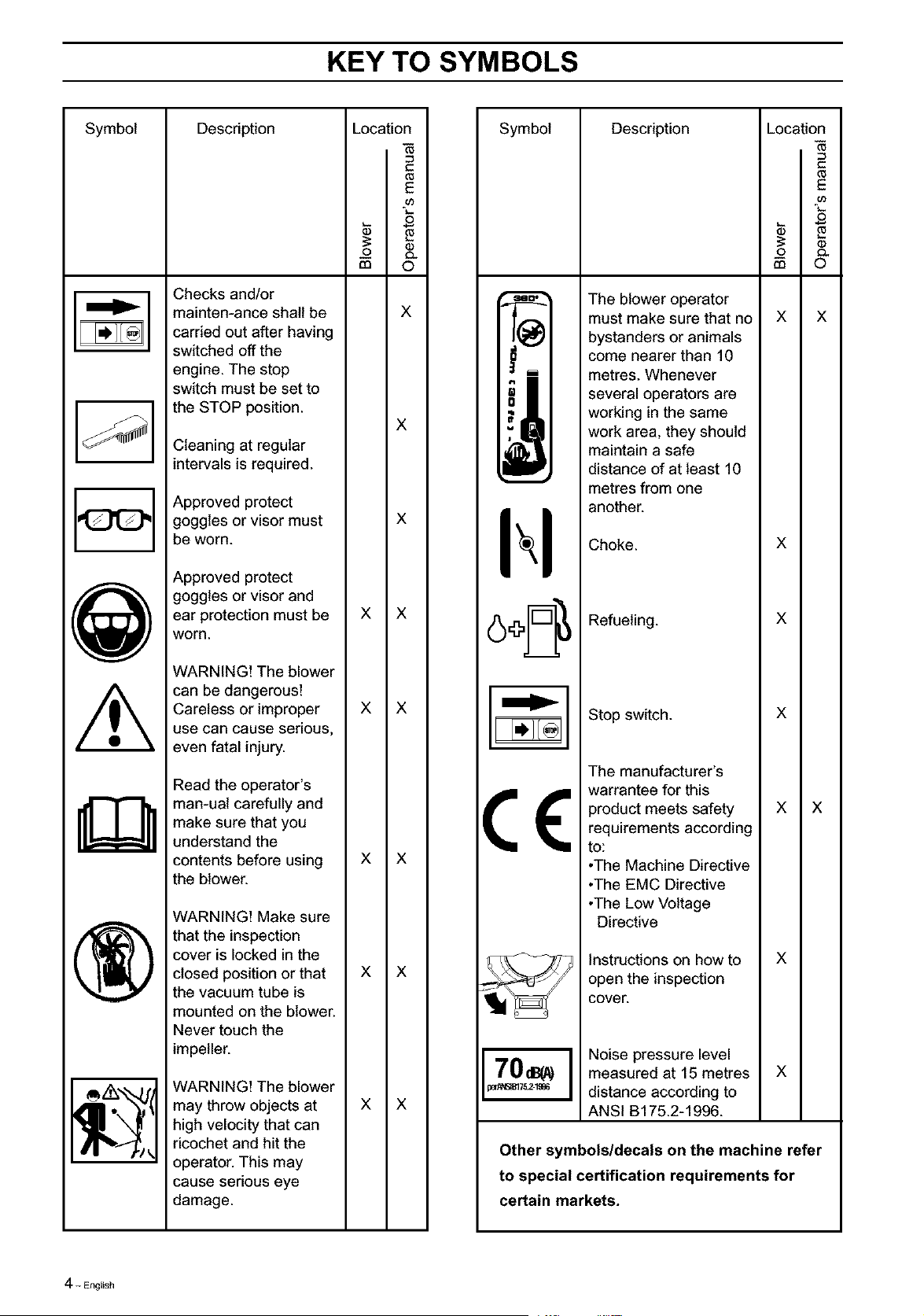
Checks and/or
mainten-ance shall be
carried out after having
switched off the
engine. The stop
switch must be set to
the STOP position.
Cleaning at regular
intervals is required.
Approved protect
goggles or visor must
be worn.
Approved protect
goggles or visor and
ear protection must be
worn.
WARNING! The blower
can be dangerous!
Careless or improper
use can cause serious,
even fatal injury.
Read the operator's
man-ual carefully and
make sure that you
understand the
contents before using
the blower.
WARNING! Make sure
that the inspection
cover is locked in the
closed position or that
the vacuum tube is
mounted on the blower.
Never touch the
impeller.
WARNING! The blower
may throw objects at
high velocity that can
ricochet and hit the
operator. This may
cause serious eye
damage.
Location
(8
E
o_
o
_o o.
m 0
X
X
X
X X
X X
X X
X X
X X
Symbol
#.
• i
70d80
d&_175.2-1996
Description Location
(8
E
o_
o
_ e
0 _
m ©
The blower operator
must make sure that no
bystanders or animals
come nearer than 10
metres. Whenever
several operators are
working in the same
work area, they should
maintain a safe
distance of at least 10
metres from one
another.
Choke.
Refueling.
Stop switch.
The manufacturer's
warrantee for this
product meets safety
requirements according
to:
•The Machine Directive
•The EMC Directive
•The Low Voltage
Directive
instructions on how to
open the inspection
cover.
Noise pressure level
measured at 15 metres
distance according to
ANSi B175.2-1996.
X
X
X
X
X
X
X
X
X
Other symbols/decals on the machine refer
to special certification requirements for
certain markets.
4- English
SAFETY INSTRUCTIONS
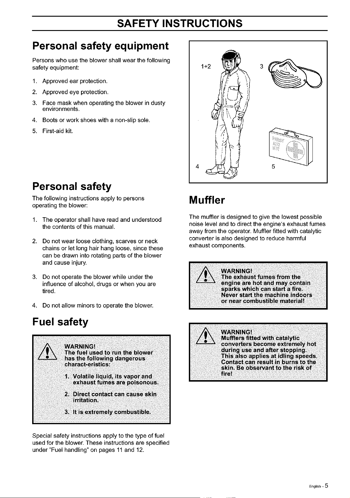
Personal safety equipment
Persons who use the blower shall wear the following
safety equipment:
1. Approved ear protection.
2. Approved eye protection.
3. Face mask when operating the blower in dusty
environments.
4. Boots or work shoes with a non-slip sole.
5. First-aid kit.
1+2
5
Personal safety
The following instructions apply to persons
operating the blower:
1. The operator shall have read and understood
the contents of this manual.
2. Do not wear loose clothing, scarves or neck
chains or let long hair hang loose, since these
can be drawn into rotating parts of the blower
and cause injury.
3. Do not operate the blower while under the
influence of alcohol, drugs or when you are
tired.
4. Do not allow minors to operate the blower.
Fuel safety
Muffler
The muffler is designed to give the lowest possible
noise level and to direct the engine's exhaust fumes
away from the operator. Muffler fitted with catalytic
converter is also designed to reduce harmful
exhaust components.
Special safety instructions apply to the type of fuel
used for the blower. These instructions are specified
under "Fuel handling" on pages 11 and 12.
English - 5

SAFETY INSTRUCTIONS
Safety equipment
The blower is equipped with a number of safety
devices and guards for the prevention of accidents.
These are described in the general description of
the blower on page 8.
The safety devices and guards also require regular
inspection and maintenance. These measures and
the interval at which they should be carried out are
specified under "Maintenance" on pages 23 and 24.
Safety while operating the
blower
Other safety measures
1. Do not allow bystanders or animals to be in the
work area, i.e. 10 metres from the operator.
2. The blower may throw objects at high velocity
that can ricochet and hit the operator. This may
cause serious eye damage.
3. Never point the blower nozzle toward people or
animals.
4. Stop the engine before fitting or dismantling
accessories or other components.
5. Never operate the blower if any of the guards is
missing.
6. Never operate the blower in poorly ventilated
spaces where exhause fumes might otherwise
be inhaled.
7. Stop the engine before refueling.
8. The catalytic muffler is extremely hot while the
blower is running and after it has stopped. The
same applies when the blower is running at
idling speed. Be aware of the danger of fire,
especially while operating the blower near
combustible materials and/or where combustible
fumes are present.
9. Be careful, parficurlarly ifleft hand operation is
applied. Avoid any direct body contact with the
exhaust outlet area.
10. Do not operate the blower while standing on a
ladder or a stand.
1.
2.
3.
4.
5.
6.
7.
.
9.
Operate the blower only at reasonable hours,
i.e. not early in the morning or late at night when
people might be disturbed. Comply with times
listed in local ordinances. Usual recommend-
ations are 9:00 a.m. to 5:00 p.m. Monday
through Saturday.
Operate the blower at the lowest possible
throttle setting to do the job.
Check the condition of the blower before opera-
tion, especially the muffler, air intake and air
filter.
Use a rake or a broom to loosen ground debris
before blowing.
Under dusty conditions, slightly spray the work
area with a hose or use a mister attachment
when water is available.
Conserve water by using blowers instead of
hoses for many lawn and garden applications,
including areas such as roof gutters, screens,
patios and gardens etc.
Watch out for children, pets, open windows or
freshly washed cars, and blow debris safely
away.
Use the full nozzle extension so the air stream
can work close to the ground.
After using the blower, clean up and dispose of
debris in trash receptacles
6- EngEish
DESCRIPTION
The blower
1 2 3 4 5
18
7
19
15
14
20
10
9
8
21
7 13 12 11
225Bx.sERIE s
6
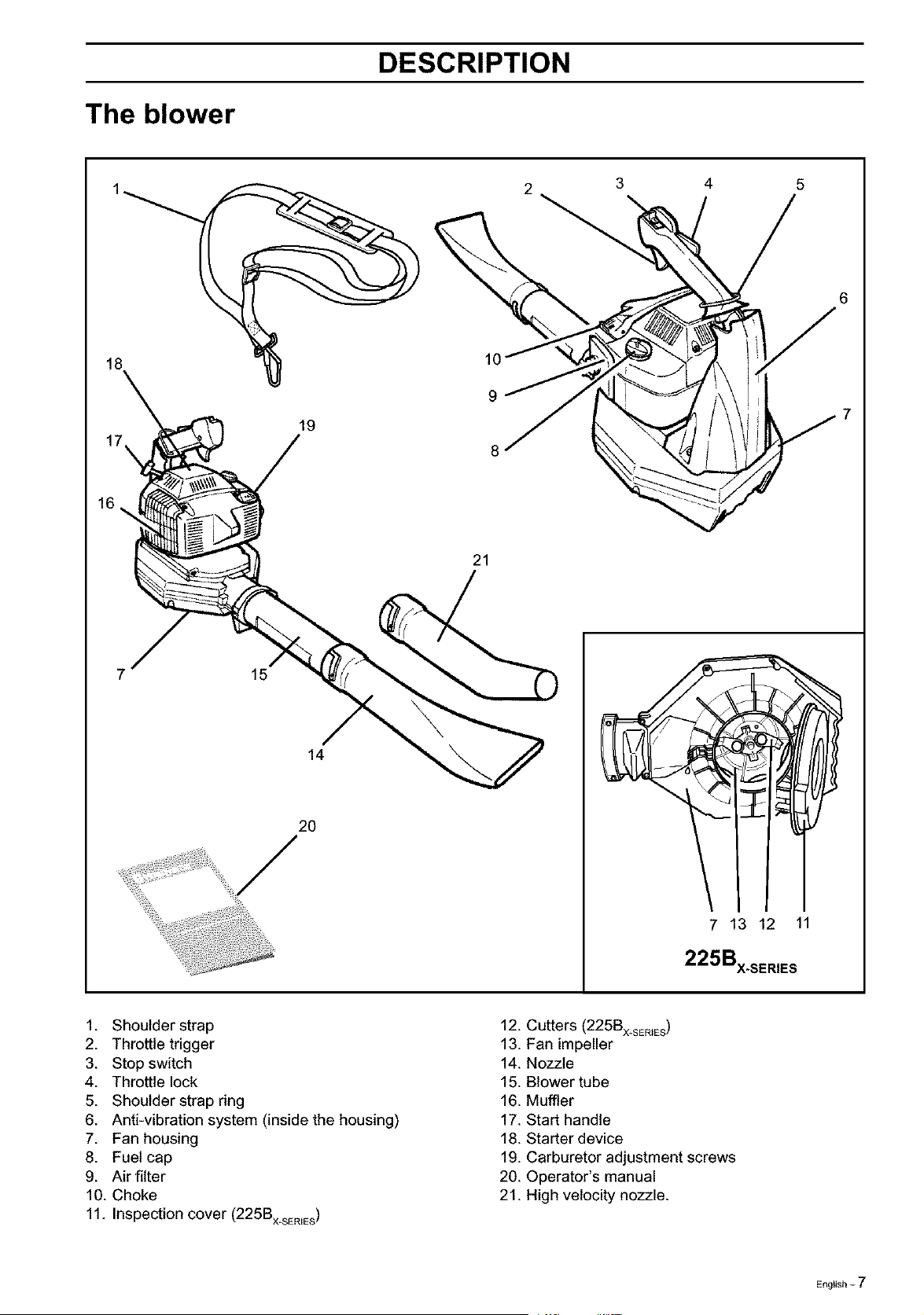
1. Shoulder strap
2. Throttle trigger
3. Stop switch
4. Throttle lock
5. Shoulder strap ring
6. Anti-vibration system (inside the housing)
7. Fan housing
8. Fuel cap
9. Air filter
10. Choke
11. Inspection cover (225Bx_sER_ES)
12. Cutters (225Bx SER_ES)
13. Fan impeller
14. Nozzle
15. Blower tube
16. Muffler
17. Start handle
18. Starter device
19. Carburetor adjustment screws
20. Operator's manual
21. High velocity nozzle.
English - 7
DESCRIPTION
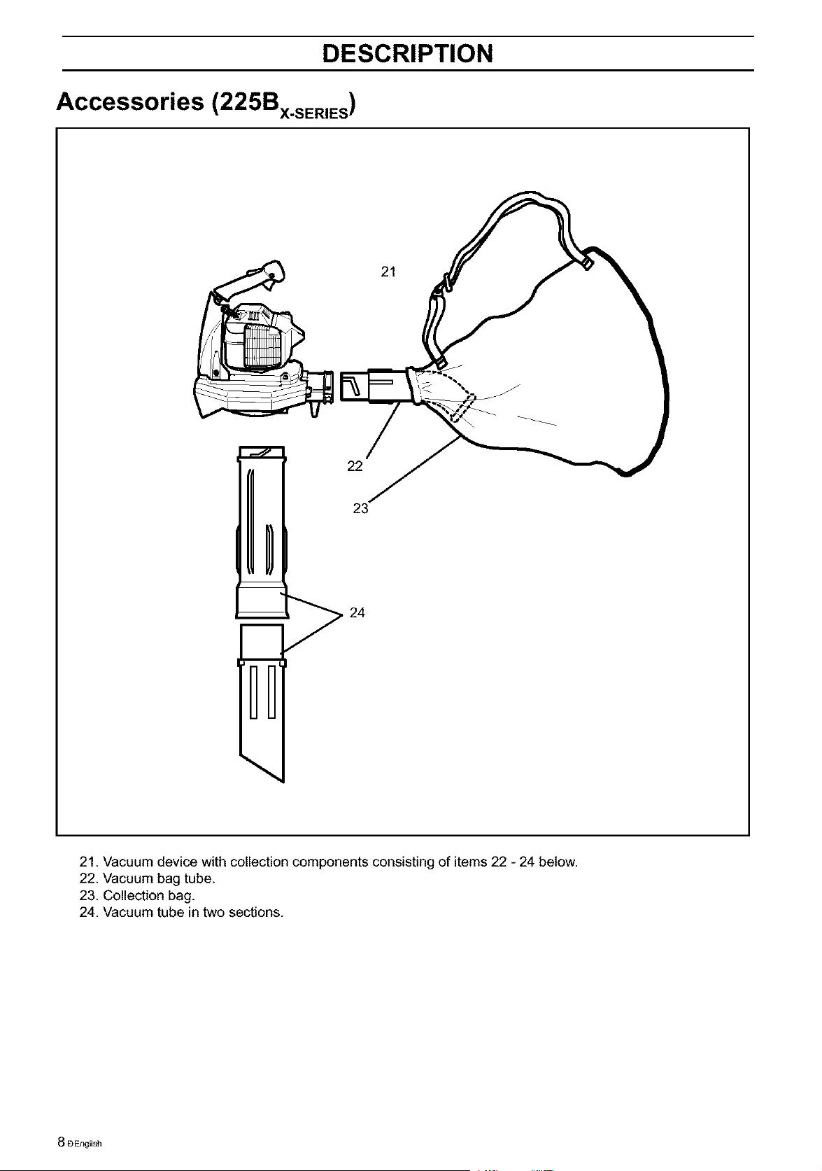
Accessories (225Bx.sER,ES)
22
24
21
\
21. Vacuum device with collection components consisting of items 22 - 24 below.
22. Vacuum bag tube.
23. Collection bag.
24. Vacuum tube in two sections.
8 DEngEish
DESCRIPTION
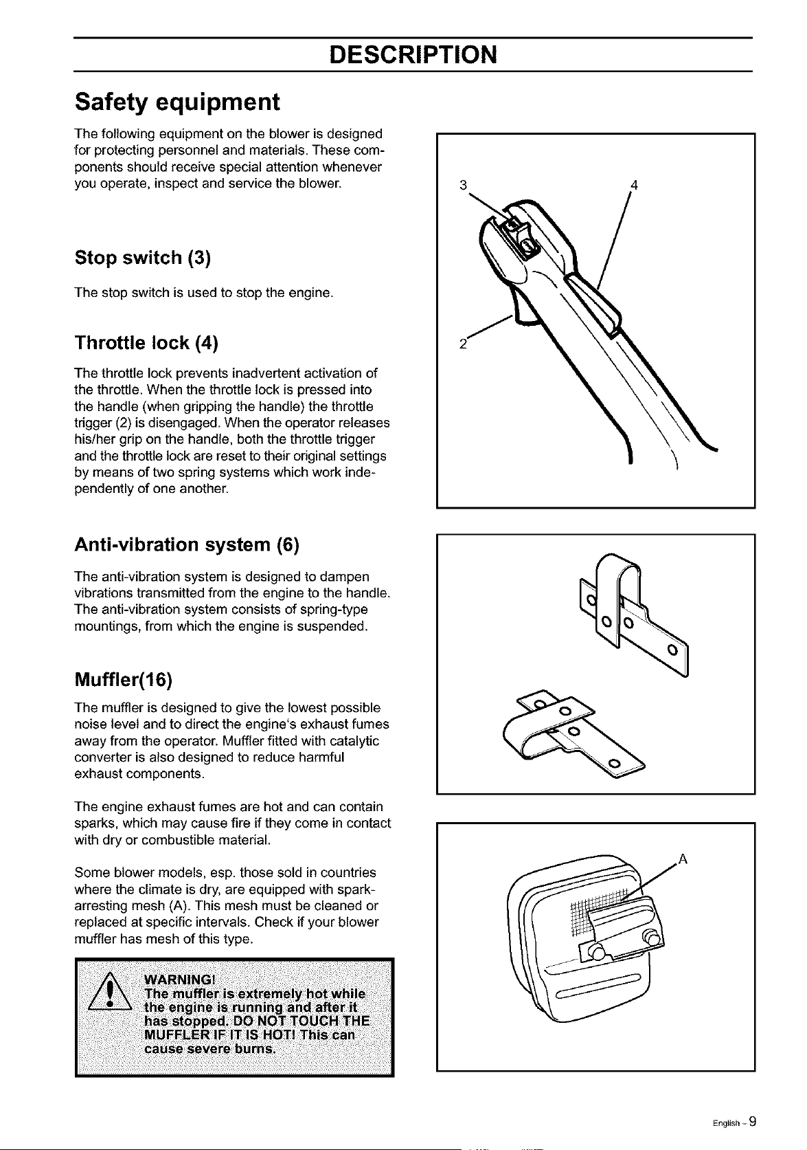
Safety equipment
The following equipment on the blower is designed
for protecting personnel and materials. These com-
ponents should receive special attention whenever
you operate, inspect and service the blower.
Stop switch (3)
The stop switch is used to stop the engine.
Throttle lock (4)
The throttle lock prevents inadvertent activation of
the throttle. When the throttle lock is pressed into
the handle (when gripping the handle) the throttle
trigger (2) is disengaged. When the operator releases
his/her grip on the handle, both the throttle trigger
and the throttle lock are reset to their original settings
by means of two spring systems which work inde-
pendently of one another.
3 4
Anti-vibration system (6)
The anti-vibration system is designed to dampen
vibrations transmitted from the engine to the handle.
The anti-vibration system consists of spring-type
mountings, from which the engine is suspended.
Muffler(16)
The muffler is designed to give the lowest possible
noise level and to direct the engine's exhaust fumes
away from the operator. Muffler fitted with catalytic
converter is also designed to reduce harmful
exhaust components.
The engine exhaust fumes are hot and can contain
sparks, which may cause fire if they come in contact
with dry or combustible material.
Some blower models, esp. those sold in countries
where the climate is dry, are equipped with spark-
arresting mesh (A). This mesh must be cleaned or
replaced at specific intervals. Check if your blower
muffler has mesh of this type.
English - 9
DESCRIPTION
Other equipment
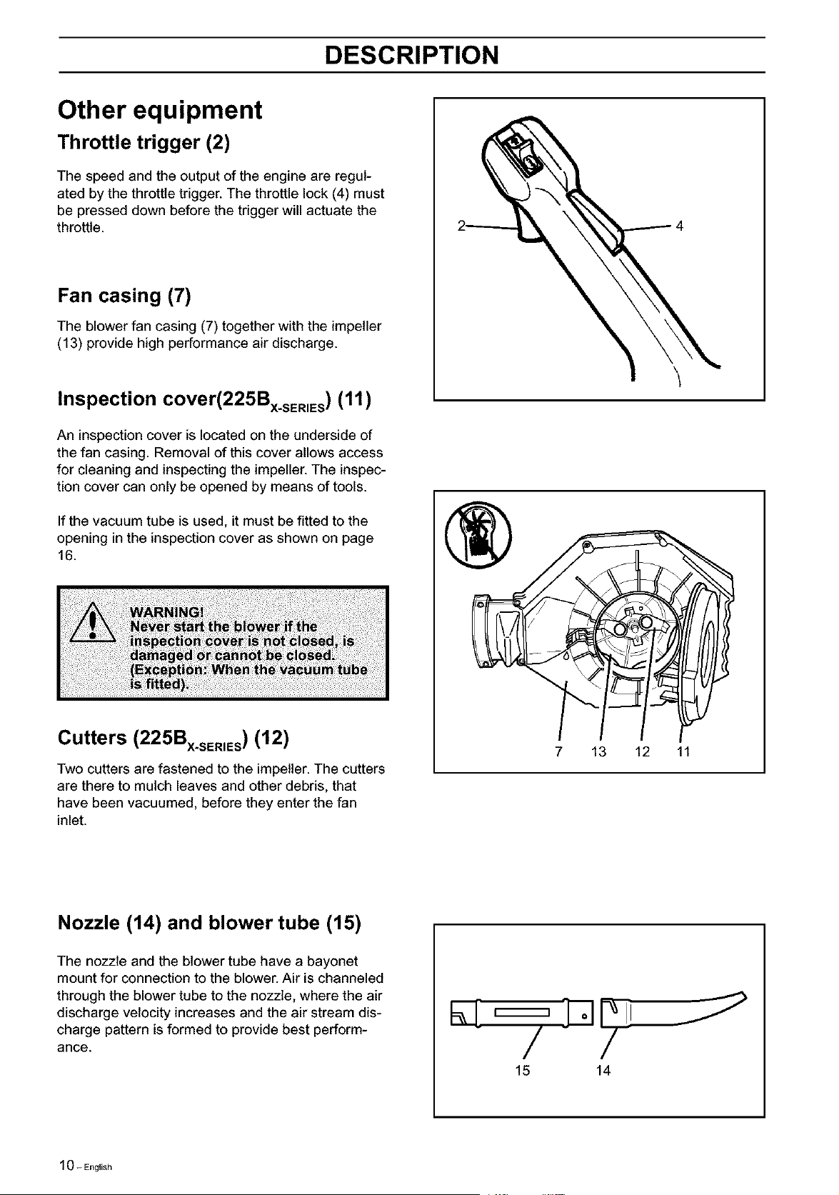
Throttle trigger (2)
The speed and the output of the engine are regul-
ated by the throttle trigger. The throttle lock (4) must
be pressed down before the trigger will actuate the
throttle.
Fan casing (7)
The blower fan casing (7) together with the impeller
(13) provide high performance air discharge.
Inspection cover(225Bx.sE._Es) (11)
An inspection cover is located on the underside of
the fan casing. Removal of this cover allows access
for cleaning and inspecting the impeller. The inspec-
tion cover can only be opened by means of tools.
If the vacuum tube is used, it must be fitted to the
opening in the inspection cover as shown on page
16.
Cutters (225Bx.sE.,Es) (12)
Two cutters are fastened to the impeller. The cutters
are there to mulch leaves and other debris, that
have been vacuumed, before they enter the fan
inlet.
®
7 13 12 11
Nozzle (14) and blower tube (15)
The nozzle and the blower tube have a bayonet
mount for connection to the blower. Air is channeled
through the blower tube to the nozzle, where the air
discharge velocity increases and the air stream dis-
charge pattern is formed to provide best perform-
ance.
15 14
1O-English
DESCRIPTION
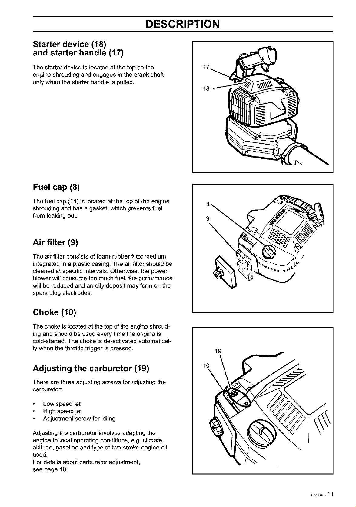
Starter device (18)
and starter handle (17)
The starter device is located at the top on the
engine shrouding and engages in the crank shaft
only when the starter handle is pulled.
18
Fuel cap (8)
The fuel cap (14) is located at the top of the engine
shrouding and has a gasket, which prevents fuel
from leaking out.
Air filter (9)
The air filter consists of foam-rubber filter medium,
integrated in a plastic casing. The air filter should be
cleaned at specific intervals. Otherwise, the power
blower wilt consume too much fuel, the performance
will be reduced and an oily deposit may form on the
spark plug electrodes.
8
9
/
Choke (10)
The choke islocated at the top of the engine shroud-
ing and should be used every time the engine is
cold-started. The choke is de-activated automatical-
ly when the throttle trigger is pressed.
Adjusting the carburetor (19)
There are three adjusting screws for adjusting the
carburetor:
Low speed jet
High speed jet
Adjustment screw for idling
Adjusting the carburetor involves adapting the
engine to local operating conditions, e.g. climate,
altitude, gasoline and type of two-stroke engine oil
used.
For details about carburetor adjustment,
see page 18.
10
19
English - 11
FUEL HANDLING
Fuel mixture
NOTEt
The machine is fitted with a two-stroke engine and
must always be run on a mixture of gasoline and
two-stroke oil. It is important to measure the quantity
of oil accurately, to ensure the correct mixture ratio.
Small discrepancies in the amount of oil have a
great bearing on the proportions of the fuel mixture
when mixing small amounts of fuel.
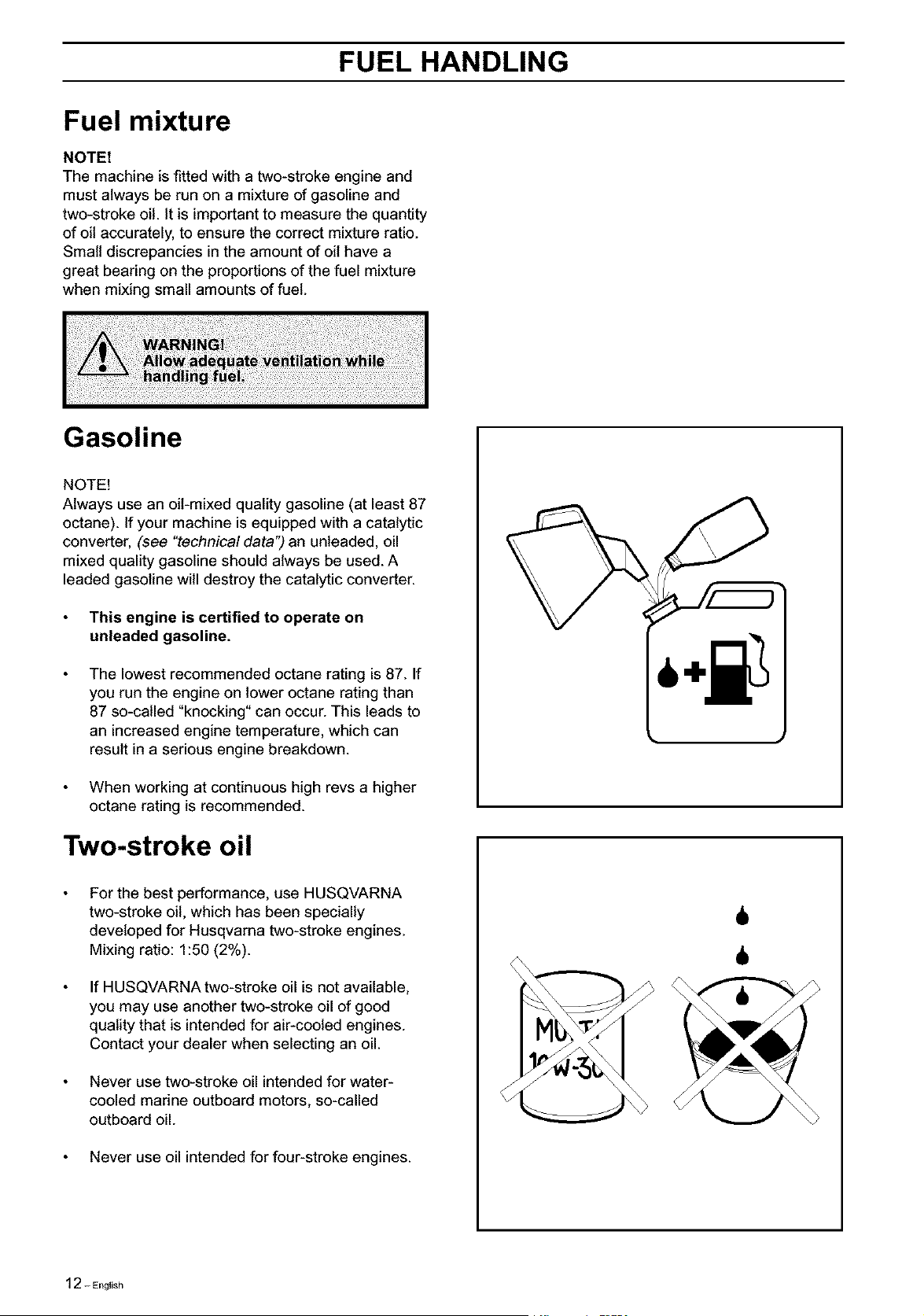
Gasoline
NOTE!
Always use an oil-mixed quality gasoline (at least 87
octane). If your machine is equipped with a catalytic
converter, (see "technical data") an unleaded, oil
mixed quality gasoline should always be used. A
leaded gasoline will destroy the catalytic converter.
This engine is certified to operate on
unleaded gasoline.
The lowest recommended octane rating is 87. If
you run the engine on lower octane rating than
87 so-called "knocking" can occur. This leads to
an increased engine temperature, which can
result in a serious engine breakdown.
When working at continuous high revs a higher
octane rating is recommended.
Two-stroke oil
For the best performance, use HUSQVARNA
two-stroke oit, which has been specially
developed for Husqvama two-stroke engines.
Mixing ratio: 1:50 (2%).
If HUSQVARNA two-stroke oil is not available,
you may use another two-stroke oil of good
quality that is intended for air-cooled engines.
Contact your dealer when selecting an oil.
Never use two-stroke oil intended for water-
cooled marine outboard motors, so-called
outboard oil.
Never use oil intended for four-stroke engines.
6
6
12 - English
FUEL HANDLING
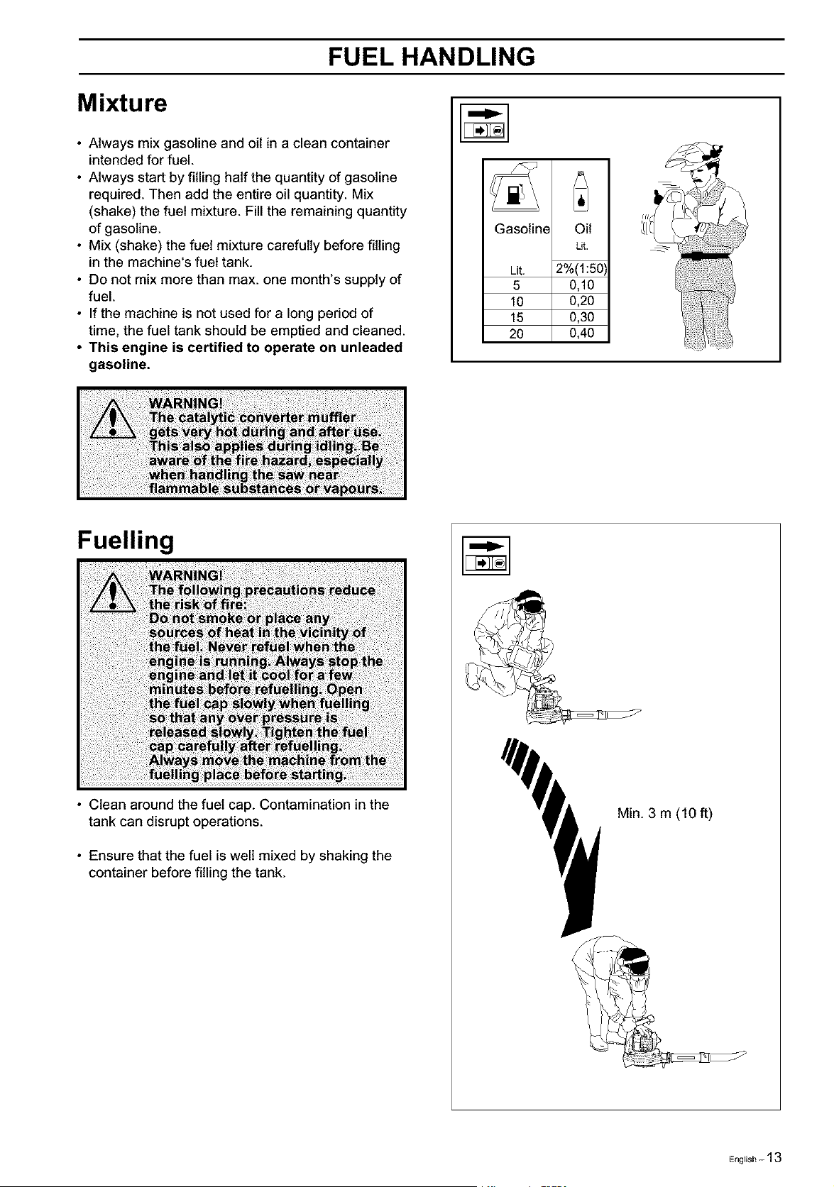
Mixture
• Always mix gasoline and oil in a clean container
intended for fuel.
• Always start by filling half the quantity of gasoline
required. Then add the entire oil quantity. Mix
(shake) the fuel mixture. Fill the remaining quantity
of gasoline.
• Mix (shake) the fuel mixture carefully before filling
in the machine's fuel tank.
• Do not mix more than max. one month's supply of
fuel.
• Ifthe machine is not used for a long period of
time, the fuel tank should be emptied and cleaned.
• This engine is certified to operate on unleaded
gasoline.
Gasoline Oil
Lit. -_
Lit. 2%(1:50'
5 0,10
10 0,20
15 0,30
20 0,40
Fuelling
) )))_ini _0f) )) )
S_;t hat an _ t pressu_ei
; ;; f del!!_g; p a_b before sta _i _
• Clean around the fuel cap. Contamination in the
tank can disrupt operations.
• Ensure that the fuel is well mixed by shaking the
container before filling the tank.
Min. 3 m (10 ft)
English - 13
START AND STOP
Start and stop
Start
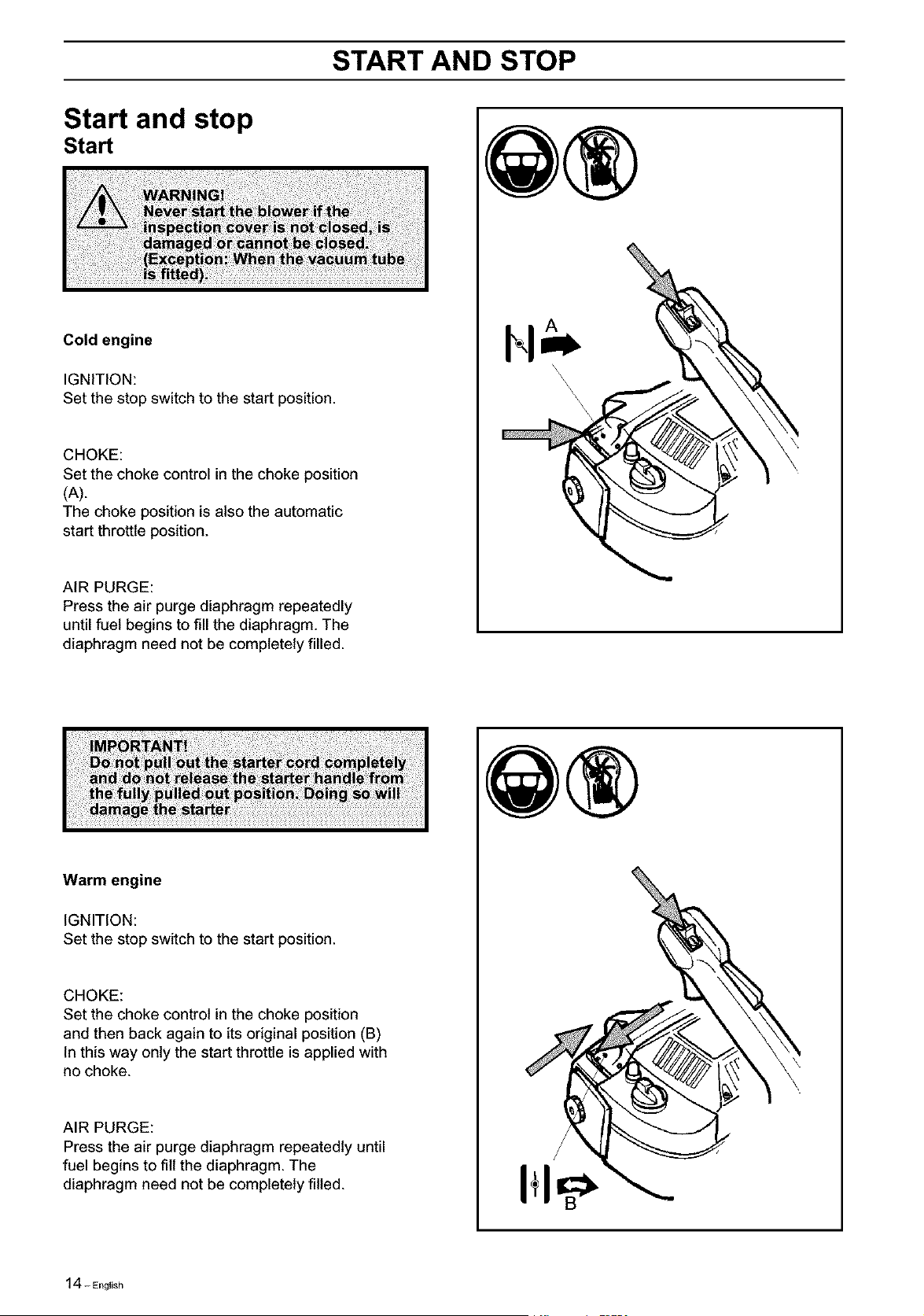
Cold engine
IGNITION:
Set the stop switch to the start position.
CHOKE:
Set the choke control in the choke position
(A).
The choke position is also the automatic
start throttle position.
AIR PURGE:
Press the air purge diaphragm repeatedly
until fuel begins to fill the diaphragm. The
diaphragm need not be completely filled.
\
\
\
\
\
\
\
\
Warm engine
IGNITION:
Set the stop switch to the start position.
CHOKE:
Set the choke control in the choke position
and then back again to its original position (B)
In this way only the start throttle is applied with
no choke.
AIR PURGE:
Press the air purge diaphragm repeatedly until
fuel begins to fill the diaphragm. The
diaphragm need not be completely filled.
I÷1
14-English
START AND STOP
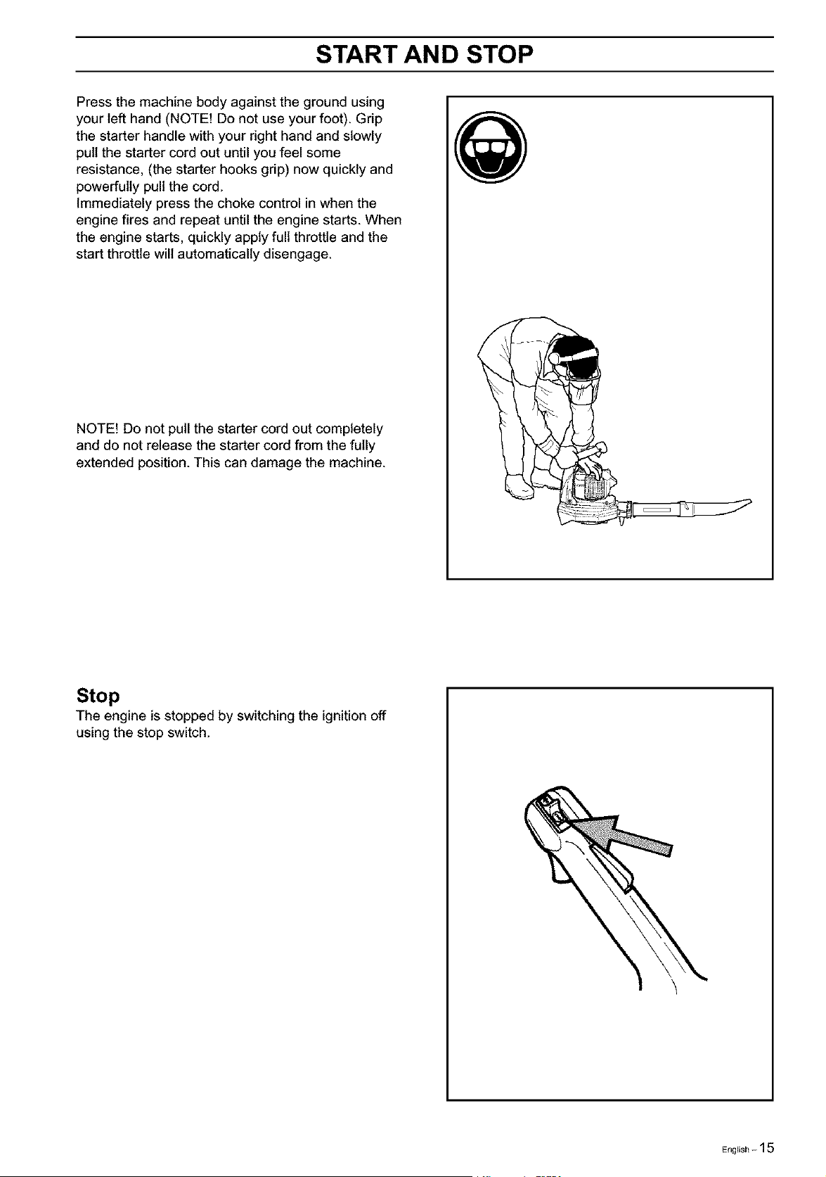
Press the machine body against the ground using
your left hand (NOTE! Do not use your foot). Grip
the starter handle with your right hand and slowly
pull the starter cord out until you feel some
resistance, (the starter hooks grip) now quickly and
powerfully pull the cord.
Immediately press the choke control in when the
engine fires and repeat until the engine starts. When
the engine starts, quickly apply full throttle and the
start throttle will automatically disengage.
NOTE! Do not pull the starter cord out completely
and do not release the starter cord from the fully
extended position. This can damage the machine.
Stop
The engine is stopped by switching the ignition off
using the stop switch.
\
English - 15
USING THE BLOWER
To blow away debris on the
ground
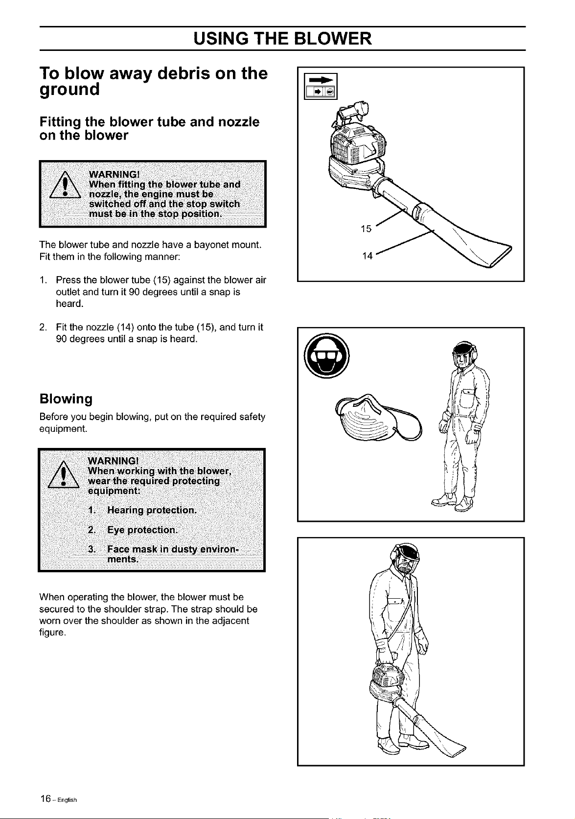
Fitting the blower tube and nozzle
on the blower
The blower tube and nozzle have a bayonet mount.
Fit them in the following manner:
1. Press the blower tube (15) against the blower air
outlet and turn it 90 degrees until a snap is
heard.
2. Fit the nozzle (14) onto the tube (15), and turn it
90 degrees until a snap is heard.
Blowing
Before you begin blowing, put on the required safety
equipment.
;i!i_!iiiii!_!!il;iii!ii!i!i_!i!iiiii_i!i_!iiiiii_ii!iii_!iiii_iiiii!iii!i!ii!!i;i!!!_!!!!i_iii_iiii!i!ii_!!ii!iiii!ili!!!!ii!!iiiiiii!i!!!iii¸
15
14
When operating the blower, the blower must be
secured to the shoulder strap. The strap should be
worn over the shoulder as shown in the adjacent
figure.
16- English
USING THE BLOWER
Start the blower as described on page 13. Work ac-
cording to the following instructions:
1. Never blow air toward fixed objects such as
walls, large rocks, automobiles and fences.
2. When working inside corners, blow from the
corner and inward toward the centre of the
work area. Otherwise, debris can fly up in your
face and cause eye injury.
3. Never point the blower nozzle at delicate plants.
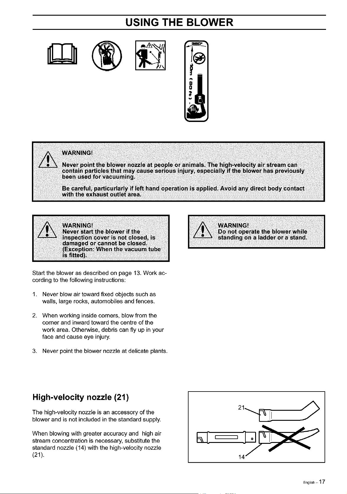
High-velocity nozzle (21)
The high-velocity nozzle isan accessory of the
blower and is not included in the standard supply.
When blowing with greater accuracy and high air
stream concentration is necessary, substitute the
standard nozzle (14) with the high-velocity nozzle
(21).
English - 17
USING THE BLOWER
Tovacuum debris from the
ground (225Bx.sER,ES)
The vacuuming device is an accessory and is not
included in the standard supply.
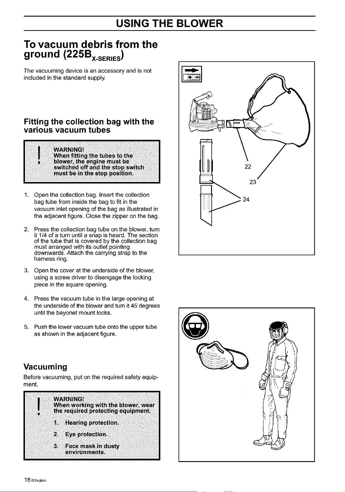
Fitting the collection bag with the
various vacuum tubes
1.
2.
.
4.
.
Open the collection bag. Insert the collection
bag tube from inside the bag to fit in the
vacuum inlet opening of the bag as illustrated in
the adjacent figure. Close the zipper on the bag.
Press the collection bag tube on the blower, turn
it 1/4 of a turn until a snap is heard. The section
of the tube that is covered by the collection bag
must arranged with its outlet pointing
downwards. Attach the carrying strap to the
harness ring.
Open the cover at the underside of the blower,
using a screw driver to disengage the locking
piece in the square opening.
Press the vacuum tube in the large opening at
the underside of the blower and turn it45 degrees
until the bayonet mount locks.
Push the lower vacuum tube onto the upper tube
as shown in the adjacent figure.
Vacuuming
Before vacuuming, put on the required safety equip-
ment.
@
22
23
18£_English
USING THE BLOWER
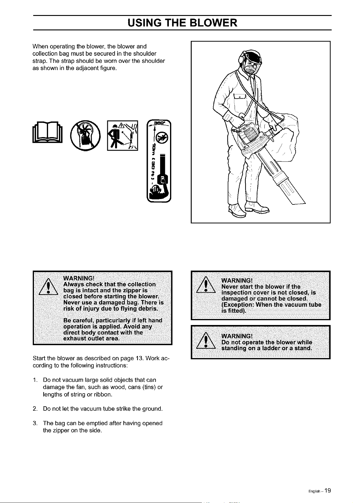
When operating the blower, the blower and
collection bag must be secured in the shoulder
strap. The strap should be worn over the shoulder
as shown in the adjacent figure.
i
0
=b
wr •
w II
li
Start the blower as described on page 13. Work ac-
cording to the following instructions:
1. Do not vacuum large solid objects that can
damage the fan, such as wood, cans (tins) or
lengths of string or ribbon.
2. Do not let the vacuum tube strike the ground.
3. The bag can be emptied after having opened
the zipper on the side.
English - 19
MAINTENANCE
Carburetor
The carburetor has been carefully preset at the fac-
tory. However, additional adjustment may be required
due to climate, altitude, gasoline and type of two-
stroke engine oil used. The instructions below
describe how carburetor adjustment should be
carried out.
The carburetor governs the engine speed via the
throttle. Air and fuel are mixed in the carburetor. The
air/fuel mixture is adjustable. To utilize the blower's
maximum output, the settings must be correct.
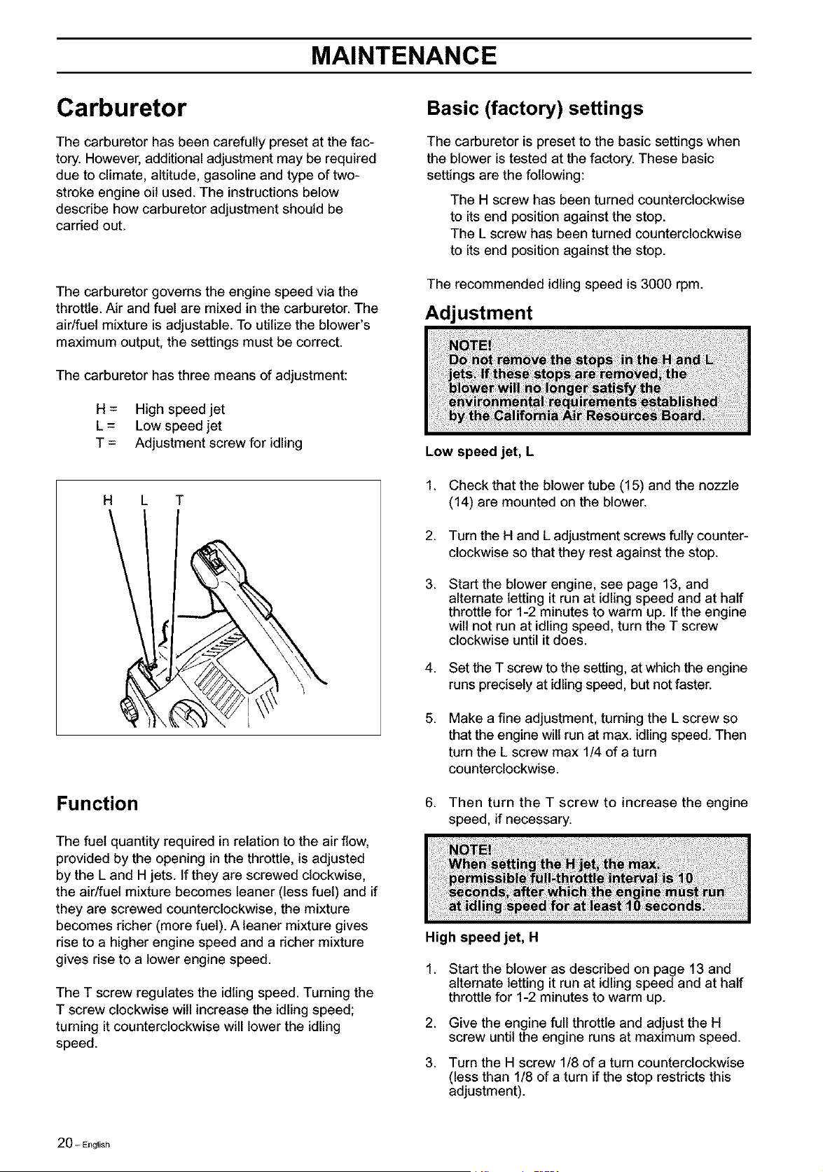
The carburetor has three means of adjustment:
H = High speed jet
L = Low speed jet
T = Adjustment screw for idling
Basic (factory) settings
The carburetor is preset to the basic settings when
the blower is tested at the factory. These basic
settings are the following:
The H screw has been turned counterclockwise
to its end position against the stop.
The L screw has been turned counterclockwise
to its end position against the stop.
The recommended idling speed is 3000 rpm.
Adjustment
H L T
Function
The fuel quantity required in relation to the air flow,
provided by the opening in the throttle, is adjusted
by the L and Hjets. if they are screwed clockwise,
the air/fuel mixture becomes leaner (less fuel) and if
they are screwed counterclockwise, the mixture
becomes richer (more fuel). A leaner mixture gives
rise to a higher engine speed and a richer mixture
gives rise to a lower engine speed.
The T screw regulates the idling speed. Turning the
T screw clockwise will increase the idling speed;
turning it counterclockwise will lower the idling
speed.
Low speed jet, L
1.
2.
3.
4.
5.
.
Check that the blower tube (15) and the nozzle
(14) are mounted on the blower.
Turn the H and L adjustment screws fully counter-
clockwise so that they rest against the stop.
Start the blower engine, see page 13, and
alternate letting it run at idling speed and at half
throttle for 1-2 minutes to warm up. If the engine
will not run at idling speed, turn the T screw
clockwise until it does.
Set the T screw to the setting, at whichthe engine
runs precisely at idlingspeed, but not faster.
Make a fine adjustment, turning the L screw so
that the engine will run at max. idling speed. Then
turn the L screw max 1/4 of a turn
counterclockwise.
Then turn the T screw to increase the engine
speed, if necessary.
High speed jet, H
1.
2.
3.
Start the blower as described on page 13 and
alternate letting it run at idling speed and at half
throttle for 1-2 minutes to warm up.
Give the engine full throttle and adjust the H
screw until the engine runs at maximum speed.
Turn the H screw 1/8 of a turn counterclockwise
(less than 1/8 of a turn if the stop restricts this
adjustment).
20- English
MAINTENANCE
Muffler
NOTEt
Some mufflers are fitted with a catalytic converter.
See "Technical data" to see whether you clearing
saw is fitted with a catalytic converter.
The muffler is designed to dampen the noise level
and to direct the exhaust fumes away from the user.
The exhaust fumes are hot and can contain sparks,
which can result in fire if the exhaust fumes are
directed towards a dry and inflammable material.
Some mufflers are equipped with a special spark
arrest screen. If your machine is fitted with this type
of screen it should be cleaned regularly. This is done
using a wire brush. On mufflers without a catalytic
converter the screen should be cleaned weekly, or
replaced if necessary. On mufflers fitted with a
catalytic converter the screen should be checked
and cleaned monthly. If the screen is damaged it
should be replaced. If the screen is frequently
blocked, this can be a sign that the function of the
catalytic converter is impaired. Contact your dealer
to inspect the muffler. A blocked screen will cause
the engine to overheat resulting in damage to the
cylinder and piston. Also see under "Maintenance"
NOTEt
Never use a machine with a defective muffler.
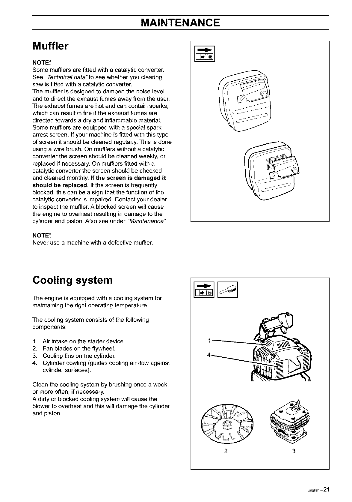
Cooling system
The engine is equipped with a cooling system for
maintaining the right operating temperature.
The cooling system consists of the following
components:
1. Air intake on the starter device.
2. Fan blades on the flywheel.
3. Cooling fins on the cylinder.
4. Cylinder cowling (guides cooling air flow against
cylinder surfaces).
Clean the cooling system by brushing once a week,
or more often, if necessary.
A dirty or blocked cooling system wilt cause the
blower to overheat and this will damage the cylinder
and piston.
-_ / f
3
English-21
MAINTENANCE
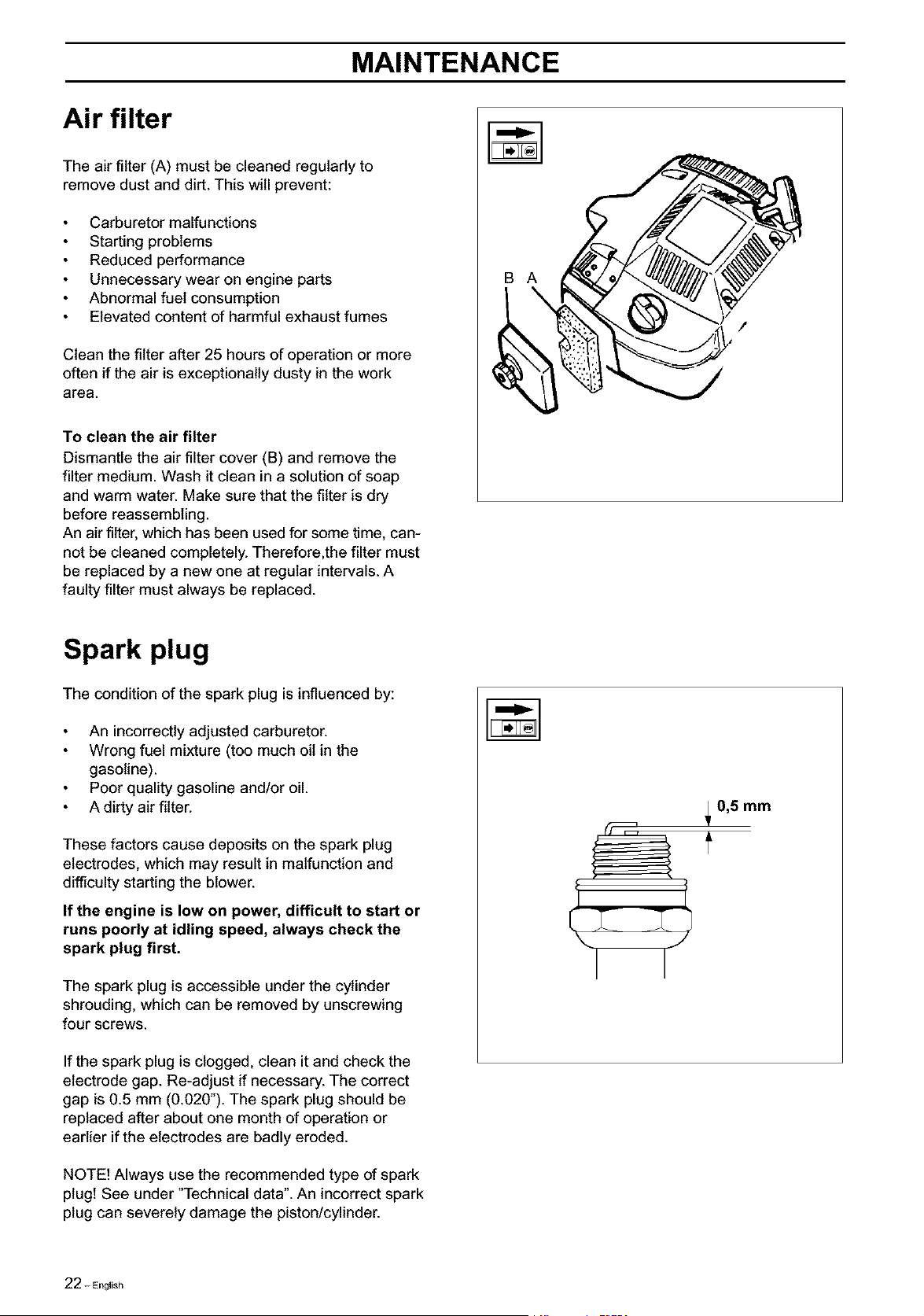
Air filter
The air filter (A) must be cleaned regularly to
remove dust and dirt. This will prevent:
Carburetor malfunctions
Starting problems
Reduced performance
Unnecessary wear on engine parts
Abnormal fuel consumption
Elevated content of harmful exhaust fumes
Clean the filter after 25 hours of operation or more
often ifthe air is exceptionally dusty in the work
area.
To clean the air filter
Dismantle the air filter cover (B) and remove the
filter medium. Wash itclean in a solution of soap
and warm water. Make sure that the filter is dry
before reassembling.
An air filter, which has been used for some time, can-
not be cleaned completely. Therefore,the filter must
be replaced by a new one at regular intervals. A
faulty filter must always be replaced.
B A
Spark plug
The condition of the spark plug isinfluenced by:
An incorrectly adjusted carburetor.
Wrong fuel mixture (too much oil in the
gasoline).
Poor quality gasoline and/or oil.
A dirty air filter.
These factors cause deposits on the spark plug
electrodes, which may result in malfunction and
difficulty starting the blower.
If the engine is low on power, difficult to start or
runs poorly at idling speed, always check the
spark plug first.
The spark plug is accessible under the cylinder
shrouding, which can be removed by unscrewing
four screws.
If the spark plug is clogged, clean it and check the
electrode gap. Re-adjust if necessary. The correct
gap is 0.5 mm (0.020"). The spark plug should be
replaced after about one month of operation or
earlier if the electrodes are badly eroded.
NOTE! Always use the recommended type of spark
plug! See under "Technical data". An incorrect spark
plug can severely damage the piston/cylinder.
_0,5 mm
22 - English
MAINTENANCE
Maintenance schedule
A number of general maintenance instructionsare
given below. If more detailed instructions are
required, get in touch with your local servicing
dealer.
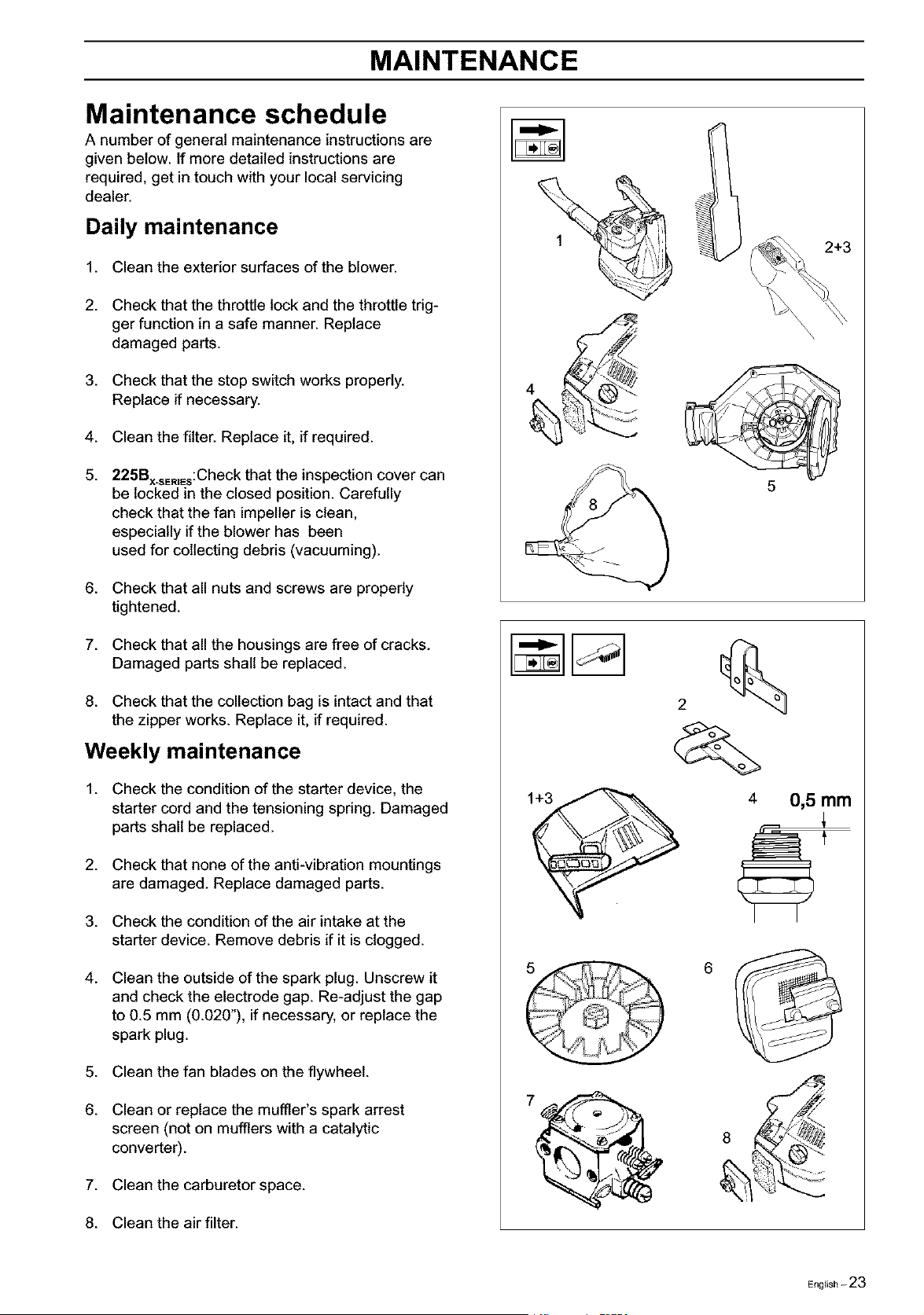
Daily maintenance
1. Clean the exterior surfaces of the blower.
2. Check that the throttle lock and the throttle trig-
ger function in a safe manner. Replace
damaged parts.
3. Check that the stop switch works properly.
Replace if necessary.
4. Clean the filter. Replace it, if required.
5. 225Bx.sER=Es:Checkthat the inspection cover can
be locked in the closed position. Carefully
check that the fan impeller is clean,
especially ifthe blower has been
used for collecting debris (vacuuming).
6. Check that all nuts and screws are properly
tightened.
7. Check that all the housings are free of cracks.
Damaged parts shall be replaced.
8. Check that the collection bag is intact and that
the zipper works. Replace it, if required.
Weekly maintenance
1. Check the condition of the starter device, the
starter cord and the tensioning spring. Damaged
parts shall be replaced.
2. Check that none of the anti-vibration mountings
are damaged. Replace damaged parts.
3. Check the condition of the air intake at the
starter device. Remove debris if it is clogged.
4. Clean the outside of the spark plug. Unscrew it
and check the electrode gap. Re-adjust the gap
to 0.5 mm (0.020"), if necessary, or replace the
spark plug.
5. Clean the fan blades on the flywheel.
6. Clean or replace the muffler's spark arrest
screen (not on mufflers with a catalytic
converter).
7. Clean the carburetor space.
8. Clean the air filter.
2+3
5
6
English-23
MAINTENANCE
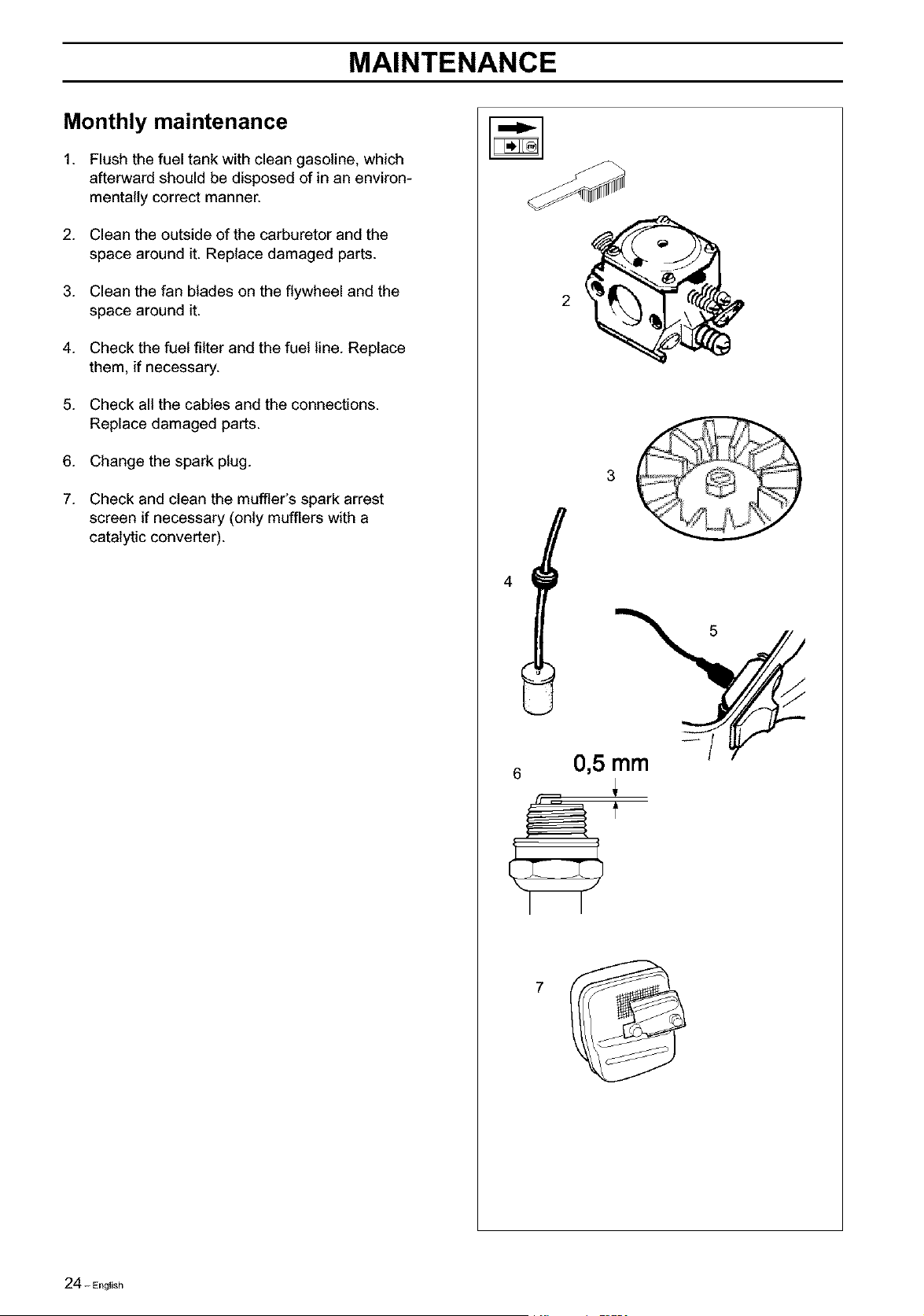
Monthly maintenance
1. Flush the fuel tank with clean gasoline, which
afterward should be disposed of in an environ-
mentally correct manner.
2. Clean the outside of the carburetor and the
space around it. Replace damaged parts.
3. Clean the fan blades on the flywheel and the
space around it.
4. Check the fuel filter and the fuel line. Replace
them, if necessary.
5. Check all the cables and the connections.
Replace damaged parts.
6. Change the spark plug.
7. Check and clean the muffler's spark arrest
screen ifnecessary (only mufflers with a
catalytic converter).
4
6
0,5 mm
f
24- English
TECHNICAL DATA
Engine
Cylinder volume, cm3:
Cylinder bore, mm:
Stroke, mm:
Idling speed, rpm:
Max. speed - blowing, rpm:
Max. speed - vacuuming, rpm:
Max. engine output to ISO 8893:
Catalytic converter muffler
Ignition system
Manufacturer/type of ignitionsystem:
Spark plug:
Electrode gap, mm:
Fuel and lubrication system
Manufacturer/type of carburetor:
Fuel tank volume, liters:
Weight
Weight, without fuel but with blower tube
and standard nozzle fitted, kg:
Noise levels
Equivalent noise pressure level at
operator's ear. Weighted value for 50%
idling and 50% full throttle to ISO 7917,
dB(A):
Equivalent sound power level. Weighted
value for 50% idling and 50% full throttle
to ISO 10884, dB(A):
Vibration levels
Vibration levels at the handle, measured
according to ISO 7916, m/s2
Idling speed, front/rear handle:
Max. speed, front/rear handle:
Fan
Type:
Max. air velocity, m/s (km/h):
Air volume using a standard nozzle, mS/h:
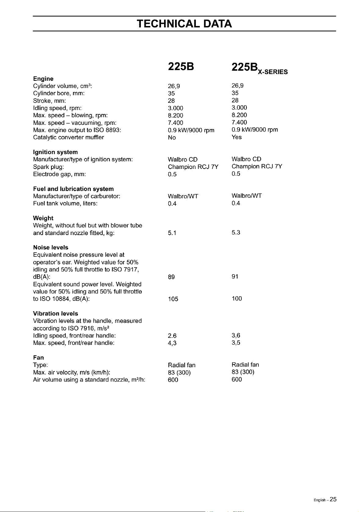
225B
225Bx.sERIES
26,9 26,9
35 35
28 28
3.000 3.000
8.200 8.200
7.400 7.400
0.9 kW/9000 rpm 0.9 kW/9000 rpm
No Yes
Walbro CD Walbro CD
Champion RCJ 7Y Champion RCJ 7Y
0.5 0.5
Walbro/WT Walbro/WT
0.4 0.4
5.1 5.3
89 91
105 100
2.6 3,6
4,3 3,5
Radial fan
83 (300)
6OO
Radial fan
83 (3O0)
6OO
English-25

FEDERAL AND CALIFORNIA EMISSION CONTROL WARRANTY STATEMENT
YOUR WARRANTY RIGHTS AND
OBLIGATIONS
The EPA (U.S. Environmental Protection Agency), CARB
(California Air Resources Board) and Husqvarna Forest &
Garden are pleased to explain the emissions control
system warranty on your 2001 and later small off-road
engine. In U.S., new small off-road engines must be
designed, built and equipped to meet the federal and
California stringent anti-smog standards. Husqvarna
Forest & Garden must warrant the emission control
system on your small off-road engine for the periods of
time listed below provided there has been no abuse,
neglect or improper maintenance of your unit.
Your emission control system includes Parts such as the
carburetor and the ignition system.
Where a warrantable condition exists, Husqvarna Forest
& Garden will repair your small off-road engine at no cost
to you. Expenses covered under warranty include diagno-
sis. parts and labor.
MANUFACTURER'S WARRANTY
COVERAGE
The 2001 and later small off-road engines are warranted
for two years. If any emission related part on your engine
(as listed above) is defective, the part will be repaired or
replaced by Husqvarna Forest & Garden.
OWNER'S WARRANTY
RESPONSIBILITIES
As the small off-road engine owner, you are responsible
for the performance of the required maintenance listed in
your Owner's Manual. Husqvarna Forest & Garden
recommends that you retain all receipts covering
maintenance on your small off-road engine, but
Husqvarna Forest & Garden cannot deny warranty solely
for the lack of receipts or for your failure to ensure the
performance of all scheduled maintenance.
As the small off-road engine owner, you should, however,
be aware that Husqvama Forest & Garden may deny you
warranty coverage if your small off-road engine or a part
of it has failed due to abuse, neglect, improper
maintenance, unapproved modifications or the use of
parts not made or approved by the original equipment
manufacturer.
You are responsible for presenting your small off-road
engine to a Husqvarna Forest & Garden authorized
servicing dealer as soon as a problem exists. The
warranty repairs should be completed in a reasonable
amount of time, not to exceed 30 days.
If you have any questions regarding your warranty rights
and responsibilities, you should contact your nearest
authorized servicing dealer or call Husqvarna Forest &
Garden at 1-800-487-5963.
WARRANTY COMMENCEMENT DATE
The warranty period begins on the date small off-road
engine is delivered.
LENGTH OF COVERAGE
Husqvarna Forest & Garden warrants to the initial owner
and each subsequent purchaser that the engine is free
from defects in materials and workmanship which cause
the failure of a warranted part for a period of two years.
IIIIIIIIIIIIIIMIIIIII
WHAT IS COVERED
REPAIR OR REPLACEMENT OF PARTS
Repair or replacement of any warranted part will be performed
at no charge to the owner at an approved Husqvama Forest &
Garden servicing dealer.
If you have any questions regarding your warranty rights and
responsibilities, you should contact your nearest authorized
servicing dealer or call Husqvama Forest & Garden at
1-800-487-5963.
WARRANTY PERIOD
Any warranted part which is not scheduled for replacement as
required maintenance, or which is scheduled only for regular
inspection to the effect of "repair or replace as necessary" shall
be warranted for 2years. Any warranted part which is scheduled
for replacement as required maintenance shall be warranted for
the period of time up to the first scheduled replacement point for
that part.
DIAGNOSIS
The owner shall not be charged for diagnostic labor which leads
to the determination that a warranted part is defective, if the
diagnostic work is performed at an approved Husqvarna Forest
& Garden servicing dealer.
CONSEQUENTIAL DAMAGES
Husqvama Forest & Garden may be liable for damages to other
engine components caused by the failure of awarranted part still
under warranty.
WHAT IS NOT COVERED
All failures caused by abuse, neglect or improper
maintenance are not covered.
ADD =ON OR MODIFIED PARTS
The useof add-on or modified parts can be grounds for disallowing
a warranty claim. Husqvama Forest & Garden is not liable to
cover failures of warranted parts caused bythe useofadd-on or
modified parts.
HOW TO FILE A CLAIM
Ifyou have any questions regarding your warranty rights and
responsibilities, you should contact your nearest authorized
servicing dealer or call Husqvama Forest & Garden at
1-800-487-5963.
WHERE TO GET WARRANTY SERVICE
Warranty services or repairs shall be provided at all
Husqvarna Forest & Garden authorized servicing dealers.
MAINTENANCE, REPLACEMENT AND
REPAIR OF EMISSION-RELATED PARTS
Any Husqvarna Forest & Garden approved replacement part
used in the performance of any warranty maintenance or
repairs on emission-related parts, will be provided without
charge to the owner if the part is under warranty.
EMISSION CONTROL WARRANTY PARTS
LIST
1.Carburetor and internal parts
2.intake pipe, airfilter holder and carburetor bolts.
3.Airfilter and fuelfilter covered up to maintainance
schedule.
4. ignition System
a) Spark Plug, covered up to maintenance schedule
b) Ignition Module
5. Muffler with catalytic converter
MAINTENANCE STATEMENT
The owner is responsible for the performance of all required
maintenance, as defined in the operator's manual.


IlllllllllllllMIIllll 2oolw32