Operator's Manual
JCRHFTSMIIN°J
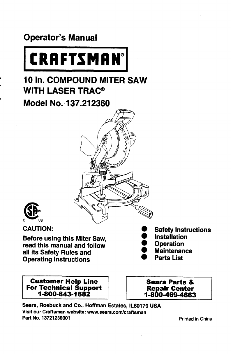
10 in. COMPOUND MITER SAW
WITH LASER TRAC _
Model No..137.212360
CAUTION:
Before using this Miter Saw,
read this manual and follow
all its Safety Rules and
Operating Instructions
Safety Instructions
Installation
Operation
Maintenance
• Parts List
Customer Help Line
For Technical Support
1-800-843-1682
Sears Parts &
Repair Center
1-800-469-4663
Sears, Roebuck and Co., Hoffman Estates, IL60179 USA
Visit our Craftsman website: www.sears.com/craftsman
Part No. 13721236001
Printed in China
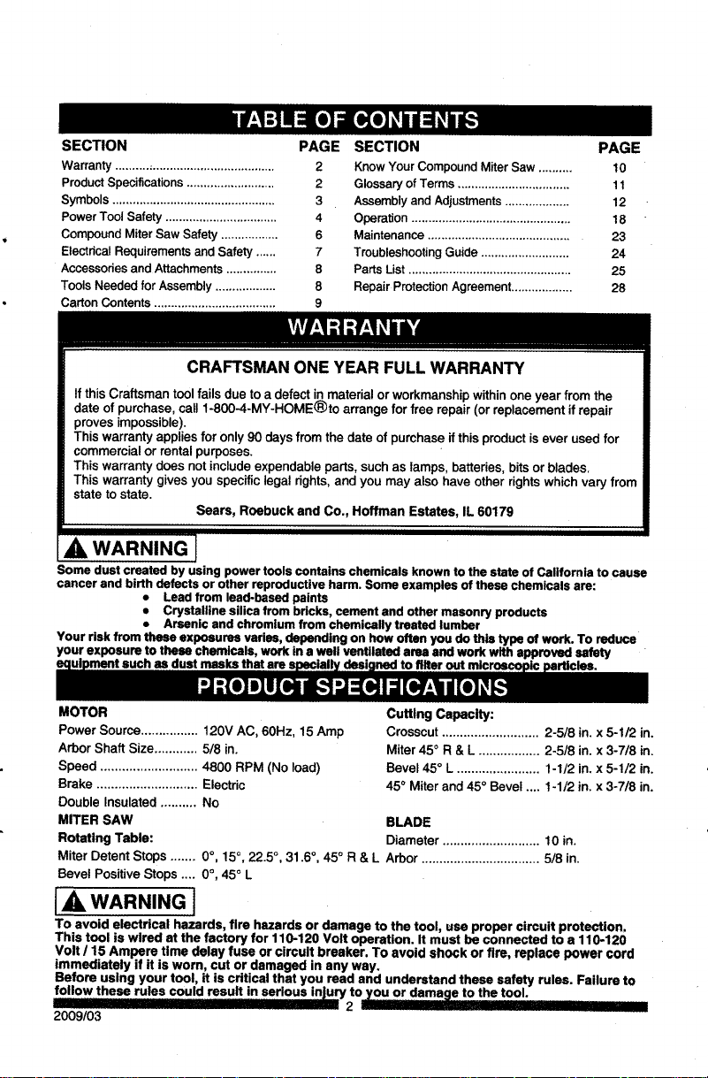
SECTION PAGE
warranty ............................................... 2
Product Specifications .......................... 2
Symbols ................................................ 3
Power Tool Safety ................................. 4
Compound Miter Saw Safety ................. 6
Electrical Requirements and Safety ...... 7
Accessories and Attachments ............... 8
Tools Needed for Assembly .................. 8
Carton Contents .................................... 9
SECTION PAGE
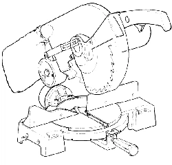
Know Your Compound Miter Saw .......... 10
Glossary of Terms ................................. 11
Assembly and Adjustments ................... 12
Operation ............................................... 18
Maintenance .......................................... 23
Troubleshooting Guide .......................... 24
Parts List ................................................ 25
Repair Protection Agreement .................. 28
CRAFTSMAN ONE YEAR FULL WARRANTY
If this Craftsman tool failsdue to a defect in material orworkmanshipwithinone year from the
date of purchase, call1-800-4-MY-HOME®to arrange for free repair(or replacement if repair
proves impossible).
This warranty appliesfor only90 daysfrom the date of purchaseifthis productisever used for
commercialor rentalpurposes.
This warranty does notincludeexpendableparts, suchas lamps, batteries,bitsor blades.
This warrantygives you specificlegal dghts, and you may also have other rightswhichvary from
state to state.
Sears, Roebuck and Co., Hoffman Estates, IL 60179
_i, WARNING J
Some dust created by using power tools contains chemicals known to the state of California to cause
cancer and birth defects or other reproductive harm. Some examples of these chemicals are:
• Lead from lead-based paints
• Crystalline silica from bricks, cement and other masonry products
• Arsenic and chromium from chemically treated lumber
Your risk from these exposures varies, depending on how often you do this type of work. To reduce
your exposure to these chemicals, work in a well ventilated area and work with approved safety
masks that are
MOTOR
Power Source................ 120V AC, 60Hz, 15 Amp
Arbor Shaft Size............ 5/8 in.
Speed ........................... 4800 RPM (No load)
Brake ............................ Electric
Double Insulated .......... No
MITER SAW
Rotating Table:
Cutting Capacity:
Crosscut ........................... 2-5/8 in. x 5-1/2 in.
Miter 450 R & L ................. 2-5/8 in. x 3-7/8 in.
Bevel 45 ° L ....................... 1-1/2 in. x 5-1/2 in.
45 ° Miter and 45 ° Bevel .... 1-1/2 in. x 3-7/8 in.
BLADE
Diameter ........................... 10 in.
Miter Detent Stops ....... 0°, 15 °, 22.5 °, 31.6 °, 45 ° R & L Arbor ................................. 5/8 in.
Bevel Positive Stops .... 0°, 45° L
IA WARNING J
To avoid electrical hazards, fire hazards or damage to the tool, use proper circuit protection,
This tool is wired at the factory for 110-120 Volt operation. It must be connected to a 110-120
Volt / 15 Ampere time delay fuse or circuit breaker, To avoid shock or fire, replace power cord
immediately if it is worn, cut or damaged in any way.
Before using your tool, it is critical that you read and understand these safety rules. Failure to
follow these rules could result in serious injury to--damage to the tool.
n 2 - I
2009/03
WARNING ICONS
Your power tool and its Operator's Manual may contain "WARNING ICONS" (a picture symbol
intended to alert you to, and/or instruct you how to avoid, a potentially hazardous condition).
Understanding and heeding these symbols will help you operate your tool better and safer.
Shown below amsome of the symbols you may see.
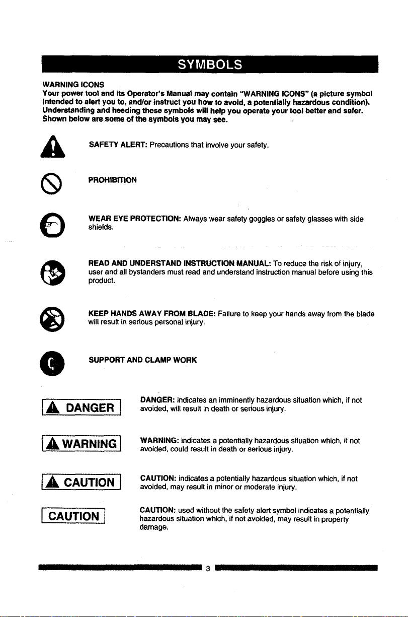
SAFETY ALERT: Precautions that involve your safety.
®
PROHIBITION
WEAR EYE PROTECTION: Always wear safety gogglesorsafety glasseswithside
shields.
READ AND UNDERSTAND INSTRUCTION MANUAL: To reduce the risk of injury,
user and all bystanders must read and understand instruction manual before using this
product,
®
KEEP HANDS AWAY FROM BLADE: Failure to keep your hands away from the blade
will result in serious personal injury.
SUPPORT AND CLAMP WORK
I,A DANGER I
IA WARNING]
I,& CAUTIONI
I CAUTIONI
DANGER: indicates an imminentlyhazardoussituationwhich,if not
avoided, willresult indeath or seriousinjury.
WARNING: indicates a potentially hazardous situation which, if not
avoided, could result in death or serious injury.
CAUTION: indicates a potentially hazardous situation which, if not
avoided, may result in minor or moderate injury.
CAUTION: used without the safety alert symbol indicates a potentially
hazardous situation which, if not avoided, may result in property
damage.
IIIIIIIII IIIIIIIIII IIII I 3 III III III
GENERALSAFETYINSTRUCTIONS
BEFOREUSINGTHISPOWERTOOL
Safetyisacombinationofcommonsense,
stayingalertandknowinghowtouseyourpower
tool.
[_IL WARNING]
To avoid mistakes that could cause serious
Injury, do not plug the tool in until you have
read and understood the following.
1. _ READ and become familiar withthe
entire Operator'sManual. LEARN
the tool's application,limitationsand
possiblehazards.
2. KEEP GUARDS IN PLACE and in working
order.
3. REMOVE ADJUSTING KEYS AND
WRENCHES. Form the habit of checking to
see that keys and adjusting wrenches are
removed from the tool before turning ON.
4. KEEP WORK AREA CLEAN, Clutteredareas
and benches inviteaccidents.
5. DO NOT USE IN DANGEROUS
ENVIRONMENTS. Do not usepower tools
in damp locations,orexpose themto rainor
snow. Keep workarea well lit.
6. KEEP CHILDREN AWAY. Allvisitorsand
bystandersshouldbe kept a safe distance
from work area.
7. MAKE WORKSHOP CHILD PROOF with
padlocks,master switchesorby removing
starterkeys.
8. DO NOT FORCE THE TOOL. Itwill dothejob
better and saferat the rate for whichit was
designed.
9. USE THE RIGHT TOOL. Do not force the tool
or an attachment to do a job for which it was
not designed.
10.USE PROPER EXTENSION CORDS. Make
sureyourextension cordis ingood condition.
When usingan extensioncord, be sureto use
one heavy enoughto carrythe currentyour
productwilldraw. An undersizedcord will
resultina dropin line voltageand inlossof
power whichwill cause the toolto overheat.
III IIIIIIII III I
The table onpage 7 showsthe correct
size to usedepending on cord length and
nameplate ampere rating.If indoubt, use the
next heavier gauge. The smallerthe gauge
number,the heavierthe cord.
11.WEAR PROPER APPAREL. Do notwear
loose clothing,gloves, neckties,rings,
braceletsor otherjewelrywhich mayget
caught in movingparts.Nonslip footwear is
recommended.Wear protectivehair covering
to containlonghair.
12.ALWAYS WEAR EYE PROTECTION. Any
O ower toolcanthrow foreignobjects
intothe eyesand could cause
permanenteye damage. ALWAYS
wear SafetyGoggles (not glasses)
that complywithANSI Safety standard Z87.1.
Everydayeyeglasses have only impact-
resistantlenses.They ARE NOT safety
glasses.Safety Goggles are availableat
Sears. NOTE: Glasses orgogglesnot in
compliance with ANSI 7.87.1 couldseriously
injureyou"when they break.
13.WEAR A FACE MASK OR DUST MASK.
Sawing operationproducesdust.
14.SECURE WORK, Use clamps or a vise to
O old work when practical. It is safer
than using your hand and it frees
both hands to operate the tool.
15.DISCONNECT TOOLS FROM POWER
SOURCE before servicing,and when
changingaccessories such as blades, bits
and cutters.
16.REDUCE THE RISK OF UNINTENTIONAL
STARTING, Make sure switch is in the OFF
position before plugging the tool in.
17.USE RECOMMENDED ACCESSORIES.
Consult this Operator's Manual for
recommended accessories. The use of
improper accessories may cause risk of injury
to yourself or others.
18.NEVER STAND ON THE TOOL. Serious
injury could occur if the tool is tipped or if the
cutting tool is unintentionally contacted.
19.CHECK FOR DAMAGED PARTS, Before
further use of the tool,a guard orother part
thatisdamaged shouldbe carefully checked
4 ---_ III
todetermine thatit willoperate properlyand
perform its intended function - checkfor
alignmentof movingpads, binding of moving
parts, breakageof pads, mountingand any
other conditionsthat may affect itsoperation.
A guard orother part thatis damagedshould
be properlyrepaired or replaced.
20,NEVER LEAVE THE TOOL RUNNING
UNATTENDED. TURN THE POWER "OFF".
Do notwalkaway from a running tooluntilthe
blade comes to a complete stop and the tool
is unpluggedfrom the powersoume.
21,DO NOT OVERREACH. Keep properfooting
and balance at all times.
22,MAINTAIN TOOLS WITH CARE. Keep
toolssharp and clean_forbest_
performance,Follow instructionsfor
lubricatingand changingaccessories,
23,WARNING: Dust generated from certain
materialscan be hazardousto your health.
Alwaysoperate saw in well-ventilatedarea
and providefor proper dustremoval.
24.1A DANGER I
People withelectronic devices, such as
pacemakers, should consult their physician(s)
before using this product. Operation of
electrical equipment in close proximity to a
heart pacemakercould cause interferenceor
failureof the pacemaker.
SPECIFICSAFETYINSTRUCTIONSFORTHIS
COMPOUNDMITERSAW
1. DO NOT USE THIN KERF BLADES they
can deflect and contact guard and can cause
possible injury to the operator.
2. DO NOT operate the miter saw until it
is completely assembled and installed
according to these instructions.
3. IF YOU ARE NOT thoroughly familiar with
the operation of miter saws, seek guidance
from your supervisor, instructor or other
qualified person.
4. ALWAYS hold the work firmly against the
fence end table. DO NOT perform any
operation free hand (use clamp wherever
possible).
5, KEEP HANDS out of the path of the saw
blade. If the workpiece you are cutting would
cause your hands to be within 6-3/4 in. of the
saw blade, the workpiece should be clamped
in place before making the cut.
6. BE SURE the blade is sharp, runs freely and
is free of vibration.
7. ALLOW the motor to come up to full speed
before starting a cut.
8. KEEP THE MOTOR AIR SLOTS CLEAN
and free of chips or dust.
9. ALWAYS MAKE SURE all handles are tight
before cutting, even if the table is positioned
in one of the positive stops.
10. BE SURE both the blade and the collar are
clean and the arbor bolt is tightened securely.
11. USE only blade collars specified for your saw.
12. NEVER use blades larger in diameter than
10 inches.
13. NEVER apply lubricants to the blade when it
is running,
14. ALWAYS check the blade for cracks or
damage before operation. Replace a cracked
or damaged blade immediately.
15. NEVER use blades recommended for
operation at less than 4800 RPM.
16. ALWAYS keep the blade guards in place and
use at all times.
17. NEVER reach around the saw blade.
18. MAKE SURE the blade is not contacting the
workpiece before the switch is turned ON.
19. IMPORTANT: After completing the cut,
release the trigger and wait for the blade to
stopbefore returningthe saw tothe raised
position.
20. MAKE SURE the blade has cometo a
completestopbefore removingor secudng
the workpiece,changingthe workpieceangle
orchangingthe angle of the blade.
21. NEVER cut metalsor masonryproductswith
thistool.This miter saw is designedfor use
on wood and wood-like products.
22. NEVER cut smallpieces. Ifthe workpiece
beingcut wouldcause your handorfingers
to be within6-3/4 in. ofthe saw bladethe
workpieceistoo small.
23. PROVIDE adequate supportto the sidesof
the saw table for longwork pieces.
24. NEVER usethe mitersaw inan area with
flammableliquidsor gases.
25. NEVER usesolvents toclean plasticparts.
Solventscould possiblydissolveor otherwise
damage the material.
26. SHUT OFF the power before servicingor
adjustingthe tool.
27. DISCONNECT the saw from the power
sourceand cleanthe machinewhen finished
using.
28. MAKE SURE the work area iscleanbefore
leavingthe machine.
29. SHOULD anypart ofyour mitersaw be
missing,damaged, or fail in any way, orany
electricalcomponentfail to perform properly,
lockthe switch and removethe plugfrom
the power supply outlet. Replace missing,
damaged, orfailed parts before resuming
operation.
POWER SUPPLY AND MOTOR
SPECIFICATIONS
The AC motor used in this saw is a universal,
nonreversible type. See "MOTOR" in the
"PRODUCT SPECIFICATIONS" section on
page 2.
IA WARNINGI
To avoid electrical hazards, fire hazards,
or damage to the tool, use proper circuit
protection. Your saw is wired at the factory
for 120 V operation. Connect to a 120 V, 15
A circuit and use a 15 A time delay fuse or
circuit breaker. To avoid shock or fire, If
power cord is worn or cut, or damaged in any
way, have it replaced immediately.
6 ...... [....
GROUNDING INSTRUCTIONS
IN THE EVENT OF A MALFUNCTION OR
BREAKDOWN, grounding provides a path of
least resistance for electric currents and reduces
the risk of electric shock. This tool is equipped
with an electrical cord that has an equipment-
grounding conductor and a grounding plug. The
plug must be plugged into a matching receptacle
that is properly installed and grounded in
accordance with all local codes and ordinances.
DO NOT MODIFY THE PLUG PROVIDED.
If it will not fit the receptacle, have the proper
receptacle installed by a qualified electrician,
IMPROPER CONNECTION of the equipment
groundingconductorcan resultin riskof electric
shock. The conductorwiththe greeninsulation
(with or withoutyellowstripes)isthe equipment
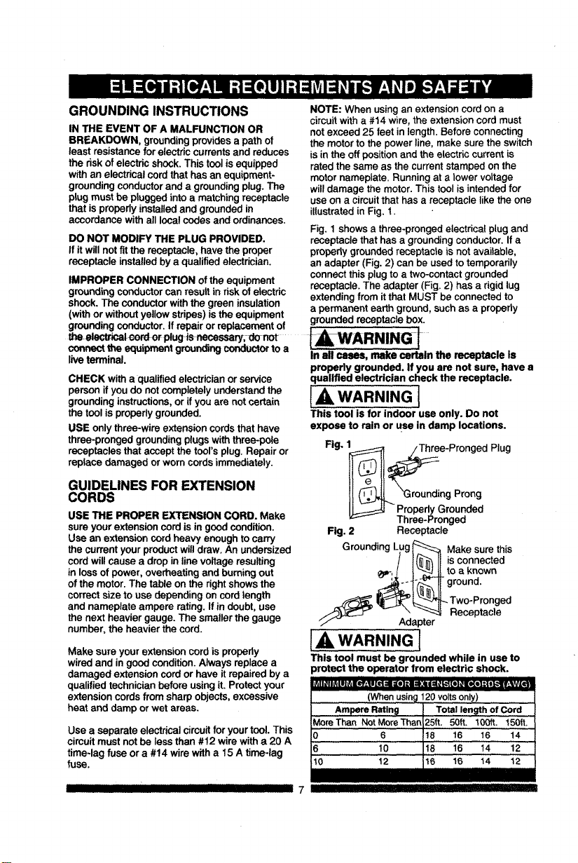
NOTE: When using an extension cord on a
circuit with a #14 wire, the extension cord must
not exceed 25 feet in length. Before connecting
the motor to the power line, make sure the switch
is in the off position and the electric current is
rated the same as the current stamped on the
motor nameplate. Running at a lower voltage
will damage the motor. This tool is intended for
use on a circuit that has a receptacle like the one
illustrated in Fig. 1.
Fig. 1 shows a three-pronged electrical plug and
receptacle that has a grounding conductor. If a
properly grounded receptacle is not available,
an adapter (Fig. 2) can be used to temporarily
connect this plug to a two-contact grounded
receptacle. The adapter (Fig. 2) has a rigid lug
extending from it that MUST be connected to
a permanent earth ground, such as a properly
groundingconductor. If repairor replacementof grounded receptaclebox.
or IAWARNiNGI
oorv_'t the equipmentgroundingconductorto a
liveterminal.
CHECK witha qualifiedelectricianorservice
person if youdo notcompletely understandthe
groundinginstructions,or ifyou are not certain
the tool isproperlygrounded.
USE onlythree-wire extensioncords thathave
three-prongedgroundingplugswiththree-pole
receptacles that accept the tool'splug.Repair or
replace damaged orworn cordsimmediately.
GUIDELINES FOR EXTENSION
CORDS
USE THE PROPER EXTENSION CORD. Make
sureyour extensioncord isin goodcondition.
Use an extensioncordheavy enoughto carry
the currentyour productwilldraw. An undersized
cordwill causea dropin linevoltage resulting
in lossof power, overheating and burningout
of the motor.The table onthe rightshowsthe
correctsize touse dependingoncordlength
and nameplate ampere rating.If in doubt,use
the next heaviergauge. The smallerthe gauge
number,the heavier the cord.
Make sureyour extension cordis properly
wiredand in goodcondition.Always replace a
damaged extensioncord orhave it repairedbya
qualifiedtechnician beforeusingit. Protectyour
extensioncordsfrom sharpobjects, excessive
heat and damp or wetareas.
iil,e] =-illi_ll r,_,_.vll
Use a separate electrical circuit for your tool. This
circuit must not be less than #12 wire with a 20 A
time-lag fuse or a #14 wire with a 15 A time-lag
fuse.
In all cases, make certain the receptacle is
properly grounded. If you are not sure, have a
qualified electrician check the receptacle.
[A WARNING l
This tool isfor indoor use only. Do not
expose to rain or use in damp locations.
Fig. 1 _i1 _:_:ee-Pronged Plug
II'-0AJ L roundingProng
ProperlyGrounded
Three-Pronged
Fig. 2 Receptacle
GroundingLug_ Make surethis
! I(_"l II iSconnected
_i-!.L ! "_'_l_lJ_to a known
IIground
Two-Pronged
...-_ _ Receptacle
U/" - Adapter
IAWARNING[
This tool must be grounded while in use to
irotect the operator from electric shock.
(When usin_l120 voltsonly)
III II III III II 7
_e,][e,]:k'.,5.-,[e]-i i:[..,fzl _ielz| ii IVzTI,];i_v_i:1_| i
RECOMMENDED ACCESSORIES
I,_ WARNING I
• Use only accessories recommended for
this miter saw. Follow instructions that
accompany accessories. Use of Improper
acceseorles may cause hazards.
• The use of any cutting tool except 10 in.
saw blades which meet the requirements
under recommended accessories is
prohibited. Do not use accessories such
as shaper cutters or dado sets. Ferrous
metal cutting and the use of abrasive
wheels is prohibited.
• Do not attempt to modify this tool or
create accessories not recommended for
use with this tool. Any such alteration or
modification is misuse and could result in
a hazardous condition leading to possible
serious injury.
ACCESSORIES
Visit your Sears Hardware Department or see the
Sears Power and Hand Tool Catalog to purchase
recommended accessories for this power tool.
[A, WARNING]
• To avoid the risk of personal injury, do not
modify this power tool or use accessories
not recommended by Sears.
• Read warnings and conditions on your
CARBIDE TIPPED SAW BLADE. Do not
operate the saw without the proper saw
blade guard in place. Carbide is a very
hard but brittle material. Care should be
taken while mounting, using, and storing
carbide Upped blades to prevent accidental
damage. Slight shocks, such as striking
the tip while handling, can seriously
damage the blade. Foreign objects in the
workpiece, such as wire or nails, can also
cause tips to crack or break off. Before
using, always visually examine the blade
and tips for bent blade, cracks, breakage,
missing or loose tips, or other damage. Do
not use if damage is suspected. Failure to
heed safety instructions and warnings can
result in serious bodily injury.
munro_o]nk,'ln+l=1:lm:lntl=+o]:ir;1.-,_-_:lmi=]m¥_
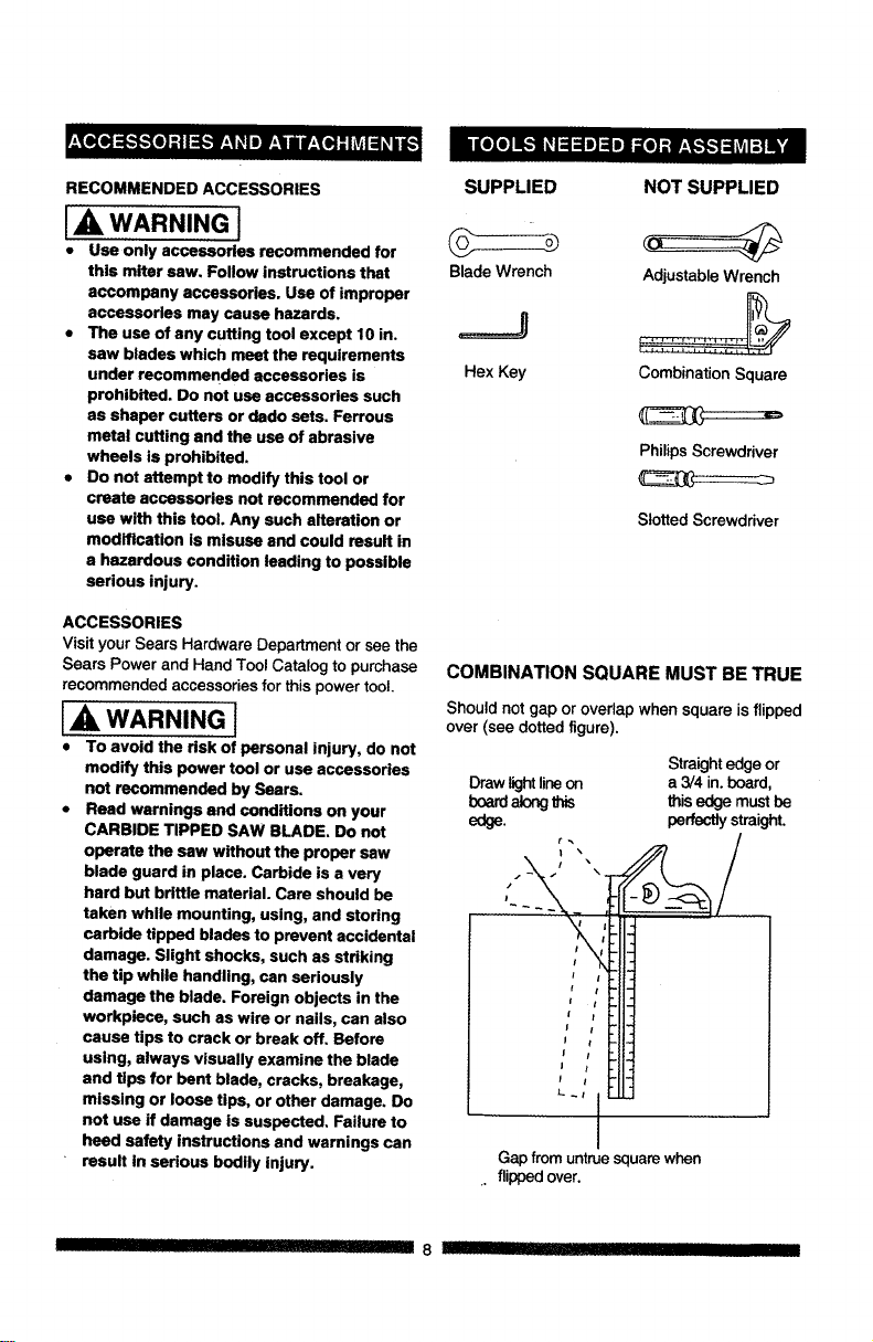
SUPPLIED NOT SUPPLIED
Blade Wrench Adjustable Wrench
=====J :::::::::::::::::::::
Hex Key Combination Square
Philips Screwdriver
Slotted Screwdriver
COMBINATION SQUARE MUST BE TRUE
Shouldnot gap or overlapwhen square is flipped
over (see dotted figure).
Straight edge or
Draw light lineon a 3/4 in. board,
board along this this edge must be
edge. perfectly straight.
ji
i !
f I
//
I I
L
Gap from untrue square when
. flipped over.
II 8 !11 _ I IIII flllllllll
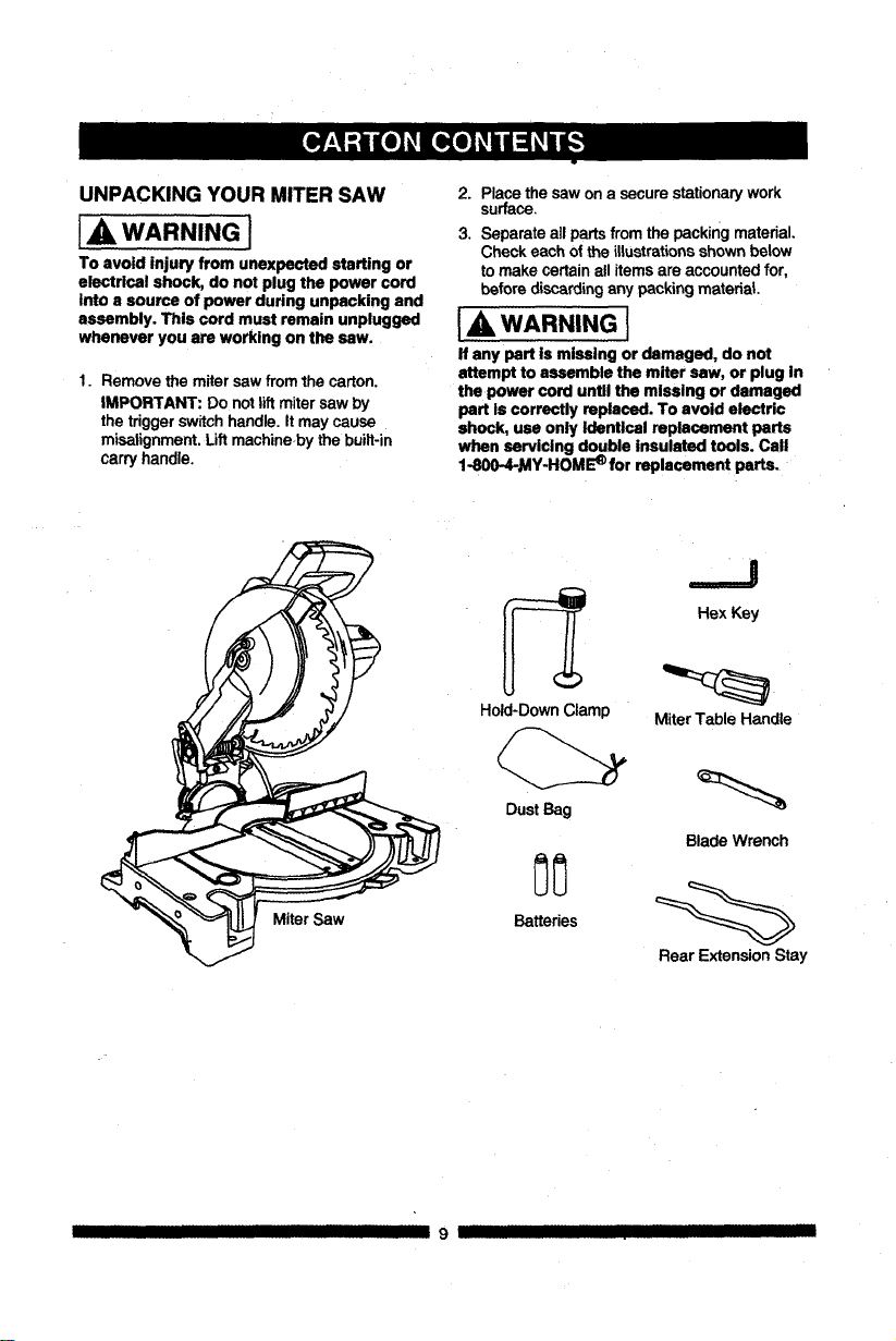
UNPACKINGYOURMITERSAW
IA WARNING I
To avoid injury from unexpected starting or
electrical shock, do not plug the power cord
into a source of power during unpacking and
assembly. This cord must remain unplugged
whenever you are working on the saw.
1. Remove the miter sawfrom the carton.
iMPORTANT: Do notlift mitersaw by
the triggerswitchhandle. It maycause
misalignment. Liftmachine bythe built-in
carry handle.
2. Placethe saw on a secure stationarywork
surface.
3. Separate allpartsfrom the packingmaterial.
Check each of the illustrationsshown below
to make certainall itemsare accountedfor,
before discardingany packing material
I,A WARNING I
If any part is missing or damaged, do not
attempt to assemble the miter saw, or plug In
the power cord untll the mlssing or damaged
part Is correctly replaced. To avoid electric
shock, usa only Identical replacement parts
when servicing double insulated tools. Call
1-800-4-_AY-HOM_ for replacement parts.
Miter Saw
Hold-DownClamp
Dust Bag
Batteries
.._J
Hex Key
MiterTable Handle
Blade Wrench
Rear Extension Stay
II III 9 IJ IIIII
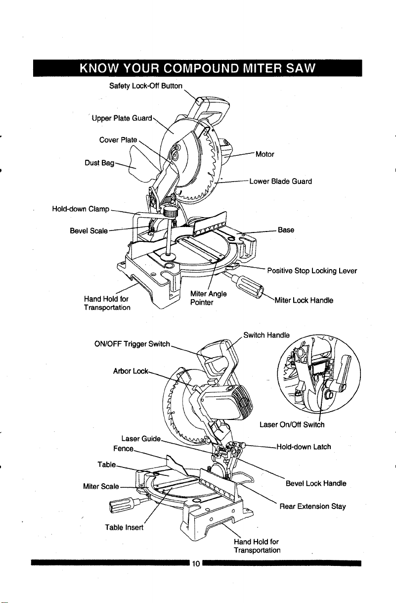
Safety Lock-Off Button
U
Cover Plate
Bevel
Hand Hold for
Transportation
MiterAngle
Pointer
Positive Stop Locking Lever
-Miter Lock Handle
ON/OFF
Arbor
LaserOn/Off Switch
Latch
Miter
Table Insert
10 II
Bevel Lock Handle
Rear Extension Stay
Hand Holdfor
Transportation
COMPOUND MITER SAW TERMS
ARBOR LOCK - Allows the user to keep the
blade fromrotating while tighteningor loosening
the arbor bolt during blade replacement or
removal.
BASE - Supports the table, holds accessories
and allows for workbench or leg set mounting.
BEVEL LOCKING HANDLE - Locks the miter
saw at a desiredbevel angle.
BEVEL SCALE -To measurethe bevel angle of
the saw blade 0°to 45° left.
COVER PLATE SCREW - Loosen this screw
and rotate theplate for access to the blade arbor
bolt.
FENCE - Helps to keep the workpiece from
moving when sawing. Scaled to assist with
accuratecutting.
LOWER BLADE GUARD - Helps protect your
hands from the blade in the raised position, it
retractsasthe blade is lowered.
MITER HANDLE - Used to rotate the table, and
to rotate the saw to a right or left cutting position.
MITER SCALE - Measures the miter angle 0° to
45 ° left and dght.
MOUNTING HOLES - To mount the miter saw to
a stable surface.
ON/OFF TRIGGER SWITCH - To start the tool,
squeeze the trigger. Release the trigger to turn
off the miter saw.
POSITIVE STOP LOCKING LEVER - Locksthe
mitersaw at a preset positivestopfor the desired
miterangle.
STOP LATCH - Locks the miter saw in the
lowered position for compact storage and
transportation.
SWITCH HANDLE - The switch handle contains
the trigger switch and the laser on/off switch. The
blade is lowered into the workpiece by pushing
down on the handle. The saw will return to its
upright position when the handle is released.
WARNING LABELS - Read and understand for
your own safety. Make sure all labels are present
I II I III IIII III I
on machineand legible.
WRENCH STORAGE - Convenient storage to
preventmisplacingthe blade wrench.
WOODWORKING TERMS
ARBOR - The shaft on which a blade is
mounted.
BEVEL CUT - An angle cut made through the
face of the workpiece.
COMPOUND CUT - A simultaneous bevel and
mitercut.
CROSS CUT - A cut made across the width of
the workpiece.
FREEHAND" Performing a cut without using a
fence (guide), hold down or other proper device
to preventthe workpiece from twistingduringthe
cuttingoperation.
GUM - A stickysap from wood products.
HEEL - Misalignmentof the blade.
KERF - The amount of material removed by
bladecut.
MITER CUT - An angle cut made across the
widthof the workpiece.
RESIN - A sticky sap that has hardened.
REVOLUTIONS PER MINUTE (RPM) - The
number of turns completed by a spinning object
in one minute.
SAW BLADE PATH - The area of the workpiece
or table top directly in line with the travel of the
blade or the part of the workpiece which will be
cut.
SET - The distance between two saw blade tips,
bent outward in opposite directions to each other.
The further apart the tips are, the greater the set.
WORKPIECE - The itembeing cut. The surfaces
of a workpiece are commonly referred to as
faces, ends andedges.
11 I IIII II IIIII I
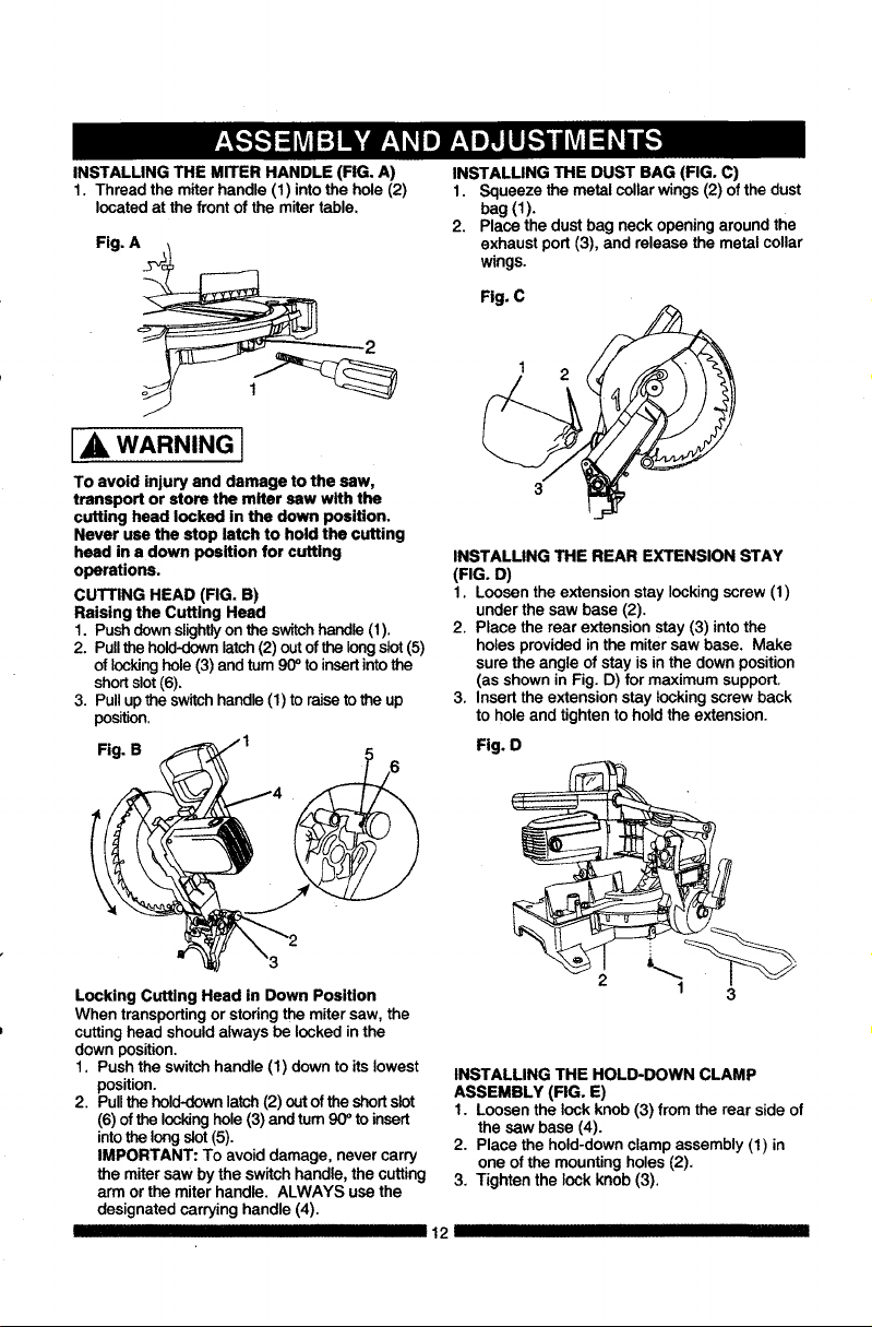
INSTALLING THE MITER HANDLE (FIG. A)
1. Thread the miter handle (1) into the hole (2)
located at the front of the miter table.
Fig. A
IA WARNING I
To avoid injury and damage to the saw,
transport or store the miter saw with the
cutting head locked in the down position.
Never use the stop latch to hold the cutting
head in a down position for cutting
operations.
CUTTING HEAD (FIG. B)
Raising the Cutting Head
1. Push clown slightlyon the switch handle (1).
2. Pull the hold-down latch (2) out of the long slot (5)
of locking hole (3) and turn 90 ° to insert into the
short slot (6).
3. Pull up the switch handle (1) to raise to the up
position.
Fig. B
Locking Cutting Head in Down Position
When transporting or storing the miter saw, the
cutting head should always be locked in the
down position.
1. Push the switch handle (1) down to its lowest
position.
2. Pull the hold-down latch (2) out of the short slot
(6) of the locking hole (3) and turn 90 ° to insert
into the long slot (5).
IMPORTANT: To avoid damage, never carry
the miter saw by the switch handle, the cutting
arm or the miter handle. ALWAYS use the
designated carrying handle (4).
III IIIIIIIIIIII I I
INSTALLING THE DUST BAG (FIG. C)
1. Squeeze the metal collar wings (2) of the dust
bag(1).
2. Place the dust bag neck opening around the
exhaust port (3), and release the metal collar
wings.
Fig. C
INSTALLING THE REAR EXTENSION STAY
(FIG. D)
I. Loosen the extensionstay lockingscrew(I)
under the saw base (2).
2. Place the rear extension stay(3) into the
holesprovided in the mitersaw base. Make
sure the angle ofstay isin the down position
(as shownin Fig. D) for maximumsupport.
3, Insert the extension stay locking screwback
to hole and tighten tohold the extension.
Fig. O
I 3
INSTALLING THE HOLD-DOWN CLAMP
ASSEMBLY (FIG. E)
1. Loosen the lock knob (3) from the rear side of
the saw base (4).
2. Place the hold-down clamp assembly (1) in
one of the mounting holes (2),
3, Tighten the lock knob (3).
12 III
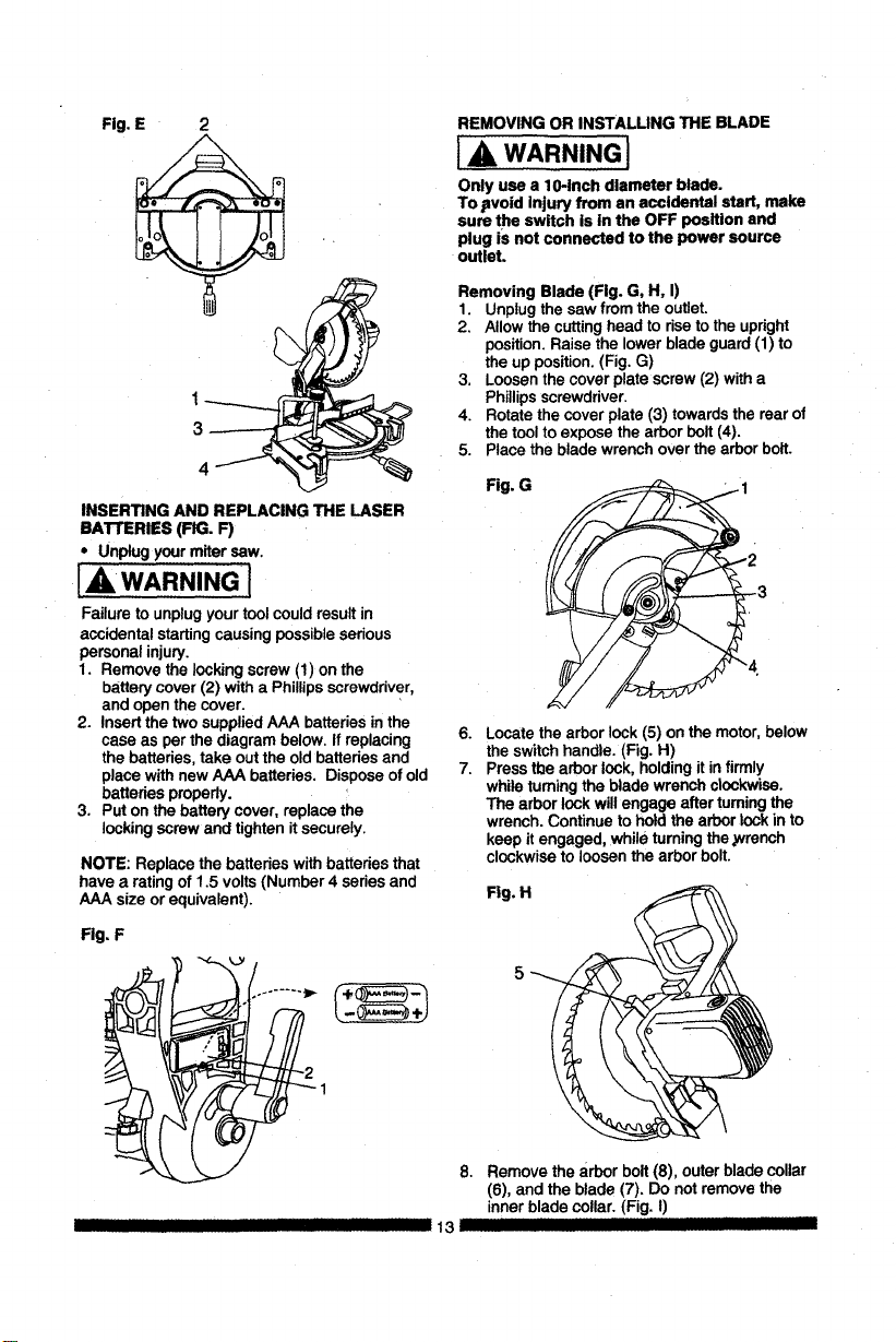
Fig.E 2
INSERTINGANDREPLACINGTHELASER
BATrERIES(FIG.F)
• Unplugyourmitersaw.
IAWARNING l
Failure to unplugyour toolcouldresultin
accidental startingcausing possibleserious
personal injury.
1. Remove the lockingscrew (1) on the
batterycover(2) with a Phillipsscrewdriver,
and open the cover.
2. Insertthe two suppliedAAA batteriesin the
case as perthe diagram below. If replacing
the batteries,take outthe old batteries and
place withnew AAA batteries. Dispose ofold
batteries properly.
3. Put onthe battery cover, replace the
locking screwand tightenit securely.
NOTE: Replace the batteries withbatteries that
have a rating of 1.5 volts(Number 4 series and
AAA size or equivalent).
Fig, F
REMOVING OR INSTALLING THE BLADE
] A, WARNING]
Only use a 10-inch diameter blade.
To .avoid injury from an accidental start, make
sure the switch is in the OFF position and
plug iS not connected tothe power source
outleL
Removing Blade (Fig. G, H, I)
1 Unplugthe saw from the outlet.
2 Allowthe cuttinghead to riseto the upright
position.Raise the lower blade guard(1) to
the up position.(Fig. G)
3 Loosenthe cover plate screw(2) witha
Phillipsscrewdriver.
4. Rotate the cover plate (3) towardsthe rear of
the toolto exposethe arborbolt (4).
5. Place the blade wrenchover the arborbolt.
Fig. G
6.
7.
Locate the arborlock (5) on the motor,below
the switchhandle. (Fig. H)
Pressthe arborlock, holdingitin firmly
while turningthe blade wrench clockwise.
The arbor lockwillengage after turningthe
wrench. Continueto holdthe arbor lockinto
keep itengaged, while turningthe ,wrench
clockwiseto loosen the arbor bolt.
Fig. H
5
8. Remove the arbor bolt(8), outer blade collar
(6), and theblade (7). Do notremove the
inner blade collar. (Fig. I)
13 JllllI III --
I II
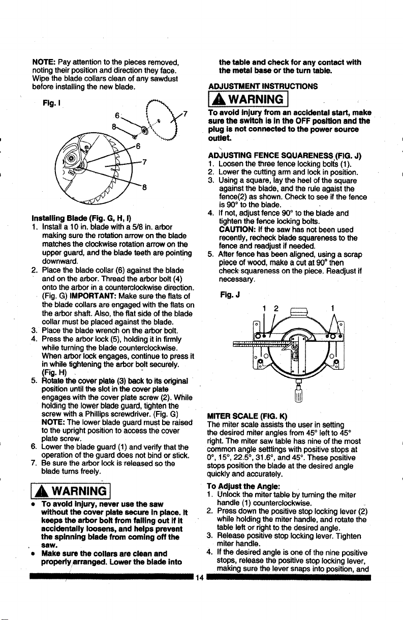
NOTE:Payattentiontothepiecesremoved,
notingtheirpositionanddirectiontheyface.
Wipethebladecollarscleanofanysawdust
beforeinstallingthenewblade.
Fig.I
,7
Installing Blade (Fig. G, H, I)
1. Installa 10 in. bladewith a 5/8 in. arbor
making surethe rotationarrow onthe blade
matches the clockwiserotationarrowon the
upper guard, and the blade teethare pointing
downward.
2. Place the blade collar(6) against the blade
and on the arbor. Thread the arborbolt(4)
ontothe arborin a counterclockwisedirection.
(Fig. G) IMPORTANT: Make sure the flats of
the blade collars are engaged withthe fiats on
the arborshaft. Also, the flat side ofthe blade
collarmustbe placed againstthe blade.
3. Place the blade wrenchon the arborbolt.
4. Pressthe arborlock(5), holdingit in firmly
while turningthe bladecounterclockwise.
When arbor lockengages, continue to press it
inwhile tighteningthe arborboltsecurely.
(Fig. H) .
5. Rotatethe cover plate (3) backto its odginal
positionuntilthe slot inthe cover plate
engages withthe cover plate screw(2). While
holdingthe lower blade guard,tightenthe
screwwitha Phillipsscrewdriver.(Fig. G)
NOTE: The lowerblade guard mustbe raised
to the uprightposition to access thecover
plate screw.
6. Lowerthe blade guard (1) and verifythatthe
operationof the guarddoes notbindorstick.
7. Besure the arbor lockis released so the
bladetums freely.
A WARNING I
• To avoid Injury, never use the saw
without the cover plate secure In place. It
keeps the arbor bolt from failing out if it
accidentally loosens, and helps prevent
the splnning blade from comlng off the
saw.
• Make sure the collars are clean and
propsdyarranged. Lower the blade into
the table and check for any contact with
the metal base or the tum table.
ADJUSTMENT INSTRUCTIONS
IA, WARNING J
To avoid Injury from an accidental start, make
sure the swItch is in the OFF position and the
plug is not connected to the power source
outlet.
AD,iUSTING FENCE SQUARENESS (FIG. J)
I. Loosenthe three fence lockingbolts(I).
2. Lower the cuttingarm and lock inposition.
3. Using a square, lay the heelof the square
againstthe blade, and the ruleagaistthe
fence(2) as shown.Check to see ifthe fence
is90° to the blade.
4. If not,adjust fence 90° to the bladeand
tighten the fence lockingbelts.
CAUTION: If the saw hasnotbeen used
recently,recheckblade squareness to the
fence and readjustif needed.
5. After fence has been aligned,usinga scrap
piece of wood, make a cut at 90° then
check squareness on the piece.Readjust if
necessary.
Fig. J
MITER SCALE (FIG. K)
The miterscale assists the user insetting
the desiredmiter anglesfrom 45° left to45°
right.The mitersaw table has nineof the most
common angle setttingswith positive stops at
0°, 15°, 22.5 °, 31.6°, and 45°. These positive
stopsposition the blade at the desired angle
quickly and accurately.
To Adjust the Angle:
1. Unlockthe mitertable by turningthe miter
handle (1) counterclockwise.
2. Pressdown the positivestoplockinglever (2)
while holdingthe miterhandle, and rotate the
table leftor rightto the desiredangle.
3. Release positive stop lockinglever.Tighten
miter handle.
4. Ifthe desiredangle is one of the nine positive
stops,release the positivestop lockinglever,
making surethe lever snapsintoposition, and
14
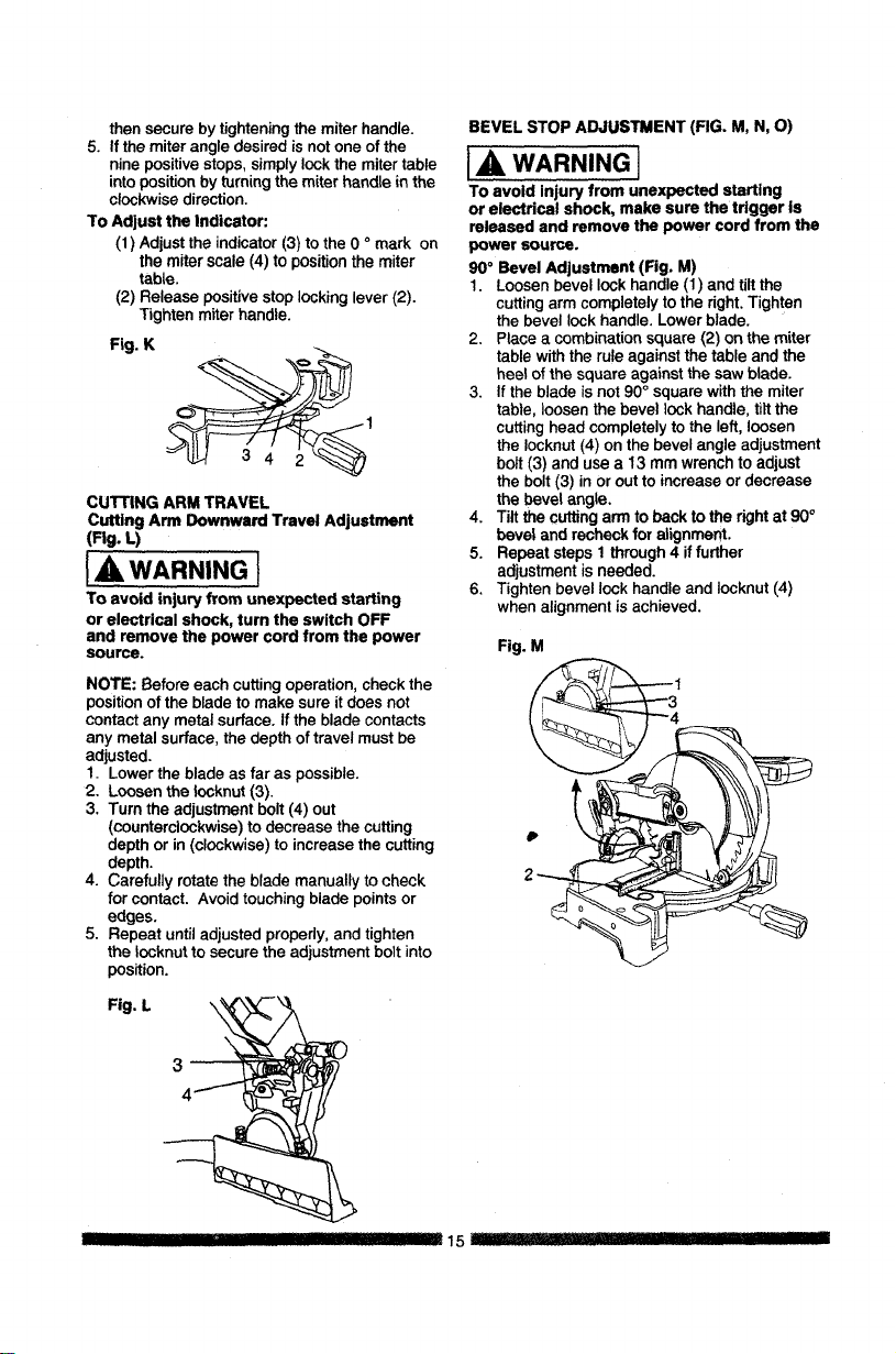
then secure by tightening the miter handle.
5. If the miter angle desired is not one of the
nine positive stops, simply lock the miter table
into position by turning the miter handle in the
clockwise direction.
To Adjust the Indicator:
(1) Adjust the indicator (3) to the 0 o mark on
the miter scale (4) to position the miter
table.
(2) Release positive stop locking lever (2).
Tighten miter handle.
Fig. K
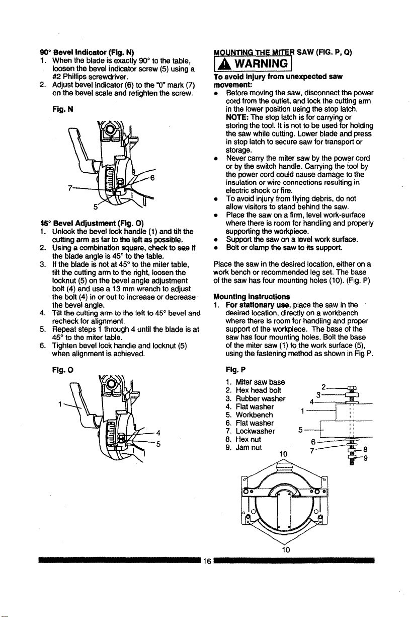
CUTTING ARM TRAVEL
Cutting Arm Downward Travel Adjustment
(Fig. L)
IA WARNING I
To avoid injury from unexpected stalling
or electrical shock, turn the switch OFF
and remove the power cord from the power
source.
NOTE: Before eachcutting operation,checkthe
positionofthe blade tomake sure itdoes not
contactany metal surface.If the blade contacts
any metal surface,the depth of travel mustbe
adjusted.
1. Lowerthe bladeas far as possible.
2. Loosenthe Iocknut (3).
3. Tum the adjustment bolt(4) out
(counterclockwise)to decrease the cutting
depthor in (clockwise)to increasethe cutting
depth.
4. Carefully rotate the blade manually to check
for contact. Avoid touchingblade pointsor
edges.
5. Repeat untiladjusted properly,and tighten
the Iocknut to secure the adjustment bolt into
position.
BEVEL STOP ADJUSTMENT (FIG. M, N, O)
I& WARNING I
To avoid injury from unexpected starting
or electrical shock, make sure the trigger is
released and remove the power cord from the
power source.
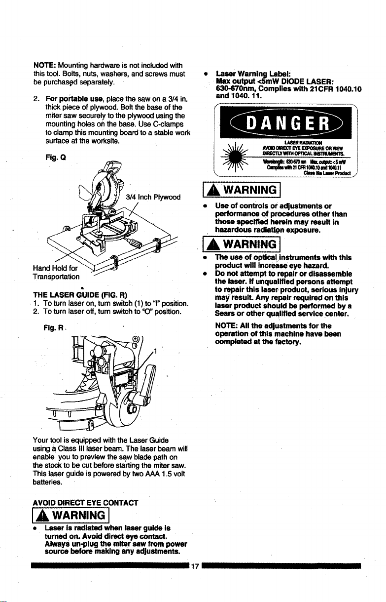
90° Bevel Adjustment (Fig, M)
1. Loosenbevel lockhandle (1) and tilt the
cuttingarm completelyto the right.Tighten
the bevellockhandle. Lowerblade.
2. Place a combinationsquare (2) on the miter
table withthe ruleagainstthe table and the
heel of the square against the saw blade.
3. If the blade isnot90° square withthe miter
table, loosen the bevel lockhandle, tilt the
cuttinghead completelyto the left,loosen
the Iocknut(4) onthe bevelangle adjustment
bolt (3) and usea 13 mm wrench to adjust
the bolt(3) inor outto increase or decrease
the bevel angle.
4. Tilt the cutting arm to back to the right at 90°
bevel and recheckfor alignment.
5. Repeat steps t through 4 if further
adjustmentisneeded.
6. Tighten bevel lock handle and Iocknut(4)
when alignmentis achieved.
Fig. M
1
Fig. L
HI I - - 15_'::: .....
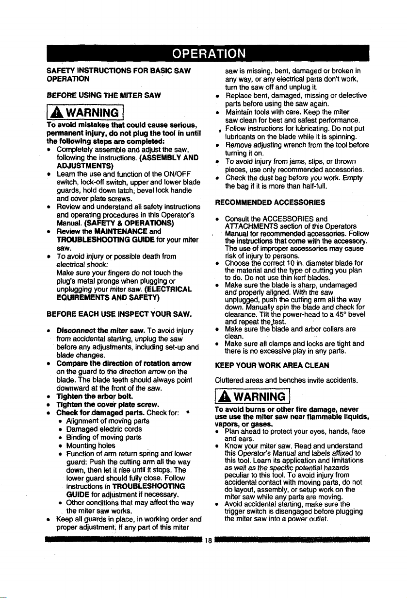
90° Bevel Indicator (Fig. N)
1. When the blade isexactly 90°to the table,
loosenthe bevel indicatorscrew(5) using a
#2 Phillipsscrewdriver.
2. Adjust bevel indicator(6)to the =0"mark(7)
on the bevel scale and retightenthe screw.
Fig. N
7-------
5/
15° Bevel Adjustment (Rg. O)
I. Unlock thebevel lockhandle (1) and tiltthe
cuttingarm as farto the left as possible.
2. Usinga combinationsquare,check to see if
the blade angle is45° tothe table.
3. Ifthe blade isnotat 45° to the mitertable,
tilt the cuttingarmto the right,loosen the
Iocknut(5) on the bevel angle adjustment
bolt(4) anduse a 13 mm wrench to adjust
the bolt(4) inor outto increaseordecrease
the bevel angle.
4. Tilt the cuttingarmto the leftto45° beveland
recheckfor alignment.
5, Repeat steps 1 through4 untilthe blade isat
45°to the mitertable.
6, Tighten bevel lockhandle and Iocknut(5)
when alignment isachieved.
Fig. 0
II IIIIIII II III
16
MOUNTING THE MITER SAW (FIG. P, Q)
IA, WARNING}
To avoid injury from unexpected saw
movement:
• Before moving the saw, disconnect the power
cord from the outlet, and lock the cutting arm
in the lower position using the stop latch.
NOTE: The stop |atch is for carrying or
storing the tool. It is not to be used for holding
the saw while cutting. Lower blade and press
in stop latch to secure saw for transport or
storage.
• Never carry the miter saw by the power cord
or by the switch handle. Carrying the tool by
the power cord could cause damage to the
insulation or wire connections resulting in
electric shock or fire.
• To avoid injury from flying debris, do not
allow visitors to stand behind the saw.
• Place the saw on a firm, level work-surface
where there is room for handling and properly
supporting the workpiece.
• Support the saw on a level work surface.
• Bolt or clamp the saw to its support.
Place thesaw inthe desired location,eitheron a
work benchor recommendedlegset. The base
of the sawhas four mountingholes (10). (Fig.P)
Mounting instructions
1. For stationary use, place the sew in the
desired location, directly on a workbench
where there is room for handling and proper
support of the workpiece. The base of the
saw has four mounting holes. Bolt the base
of the miter saw (1) to the work surface (5),
using the fastening method as shown in Fig P.
Fig. P
1. Mitersew base
2. Hex head bolt
3. Rubberwasher
4, Fiat washer
5. Workbench
6, Flatwasher
7, Lockwasher
8, Hexnut
9, Jamnut
10
10
NOTE: Mountinghardware is notincludedwith
thistool.Bolts, nuts, washers,and screwsmust
be purchas_l separately.
2.
For portable use, placethe saw on a 314 in.
thickpiece of plywood.Boltthe baseof the
mitersaw securely to the plywoodusingthe
mounting holes onthe base. Use C-clamps
to clamp this mountingboard toa stable work
surfaceat the worksite.
Fig. Q
Inch Plywood
Hand Hold for
Transportation /
THE LASER GUIDE (RG. R)
1. To turnlaser on, tum switch(1)to "1"position.
2. To turnlaser off,turn switchto "O" position.
Fig. R+
Yourtoolis equippedwiththe LaserGuide
usinga ClassIII laser beam. The laser beam will
enable you to previewthe sew bladepath on
the stocktobe cut beforestartingthe mitersaw.
This laserguide ispoweredby twoAAA 1.5 volt
batteries.
Laser Warning Label:
Max output <SmW DIODE LASER:
IS30-670nm, Complies with 21CFR 1040.10
and 1040. 11.
_ FIADWION
AVOIOI_'T EYEEXPO_IE OR_
DmL_TLY WfllH 0PTiCAL Bd81RUMBMT_
C_ _1_21CFR10S.10I',d 10W.ll
\._ Cl*n k L_er Produd •
I& WARNING I
• Use of controls or adjustments or
performance of procedures other than
those specified herein may result in
hazardous radiation exposure.
IA WARNING J
• The use of optical Instruments with this
product will increase eye hazard.
• Do not attempt to repair or disassemble
the laser. If unqualified persons attempt
to repair this laser product, serious injury
may resuIL Any repair required on this
laser product should be performed by a
Sears or other qualified service center.
NOTE: All the adjustments for the
operation of this machine have been
completed st the factory.
AVOID DIRECT EYE CONTACT
A WARNING I
• Laser is radiated when laser guide is
turned on. Avoid direct eye contact.
Always un-plug the miter sew from power
source before making any adjustments.
17 IIIIII
SAFETYINSTRUCTIONS FOR BASIC SAW
OPERATION
BEFORE USING THE MITER SAW
[_ WARNING]
To avoid mistakes that could cause serious,
permanent injury, do not plug the tool in until
the following steps are completed:
• Completelyassemble and adjUstthe saw,
followingthe instructions.(ASSEMBLY AND
ADJUSTMENTS)
• Learn the use and functionof the ON/OFF
switch,lock-off switch, upperand lower blade
guards, holddown latch; bevellockhandle
and cover plate screws.
• Review and understandall safety instructions
and operatingproceduresin thisOperator's
Manual. (SAFETY & OPERATIONS)
• Review the MAINTENANCE and
TROUBLESHOOTING GUIDE foryour miter
saw,
• To avoid injuryor possibledeathfrom
electricalshock:
Make sureyour fingersdonottouchthe
plug'smetal prongswhen pluggingor
unpluggingyour mitersaw. (ELECTRICAL
EQUlREMENTS AND SAFETY)
BEFORE EACH USE INSPECT YOUR SAW.
• Disconnect the miter saw, To avoid injury
fromaccidental starting,unplugI_ saw
before any adjustments,includingset-upand
blade changes.
• Compare the direction of rotation arrow
on the guard tothe directionarrow onthe
blade. The blade teethshouldalways point
downwardat the front of the saw.
• Tighten the arbor bolt,
• Tighten the cover plate screw,
• Check for damaged parts. Check for: •
• Alignmentof movingparts
• Damaged eleCtriccords
• Bindingofmovingparts
• Mounting holes
• Function of arm returnspringand lower
guard: Pushthe cuttingarm allthe way
down, thenlet it rise untilit stops. The
lower guardshouldfully close.Follow
instructionsinTROUBLESHOOTING
GUIDE for adjUstmentifnecessary.
• Otherconditionsthat may affect the way
the miter saw works.
• Keep allguards in place, inworkingorder and
properadjustment! Ifany partof this miter
II III
saw is missing,bent,damaged orbroken in
anyway, or anyelectricalpartsdon'twork,
turn the saw offand unplugit.
• Replace bent, damaged, missingordefective
parts beforeusingthe saw again.
• Maintaintoolswithcare. Keep the miter
sawclean for best andsafest performance.
, Followinstructionsfor lubricating.Do notput
lubricantson the bladewhile it isspinning.
• Removeadjustingwrenchfrom the tootbefore
turningit on.
• To avoid injury from jams, slips,orthrown
pieces, useonly recommendedaccessories_
• Checkthe dustbag before you work.Empty
the bag if itismore than half-fulL
RECOMMENDED ACCESSORIES
• Consult the ACCESSORIES and
ATTACHMENTS sectionofthis Operators
Manual for recommendedaccessories. Follow
the insb'uctionsthat come withthe accessory,
The useof improperaccessoriesmaycause
riskofinjurytopersons.
• Choose the correct 10 in.diameter blade for
the materialand thetype ofcuttingyou plan
to do. Do notusethinkerf blades.
• Make surethe blade issharp, undamaged
and properlyaligned.With the saw
unplugged,pushthe cuttingarmallthe way
down.Manually spinthe blade and checkfor
clearance.Tilt the power-headto a 45° bevel
and repeatthe,test.
• Make surethe blade andarborcollarsare
clean.
• Make sureallclampsand locksare tightand
there isno excessiveplay inany parts.
KEEP YOUR WORK AREA CLEAN
Cluttered areas and benches inviteaccidents.
l_, WARNING]
To avoid burns or other fire damage, never
use use the miter saw nearflammable liquids,
vapors, or gases.
• Planahead toprotectyoureyes, hands, face
and ears.
• Knowyour mitersaw. Read and understand
thisOperator,s Manualand labels affixed to
this tool. Learn its application and limitations
as wellas the specificpotentialhazards
peculiarto this tool.To avoid injuryfrom
accidentalcontactwithmovingparts,do not
do layout,assembly, or setup workonthe
mitersaw while any partsare moving.
• Avoidaccidentalstarting,make surethe
trigger switch is disengaged before plugging
the miter saw intoa power outlet.
18 II III IIII I1' I I'111111IIq]
PLAN YOUR WORK
• Use the right tool.Don't force a tool or
attachment to do a job it was notdesigned
to do. Use a differenttoolfor any workpiece
thatcan't be held in a solidlybraced,fixed
position.
LA CAUTIONI
This machine is not designed for cutting
masonry, masonry products, ferrous metals
(steel, iron, and iron-based metals.) Use
this miter sew to cut only wood, wood-
like products, or non-ferrous metals. Other
material may shatter, bind the blade, or create
other dangers. Remove all nails that may be
in the workpieee to prevent sparking that
could cause a fire, Remove dust bag when
cutting non-ferrous metals.
DRESS FOR SAFETY
Any powertoolcan throw foreign
objects intothe eyes. This can resultin
permanent eye damage. Everyday
eyeglasseshave onlyimpactresistantlensesand
are not safetyglasses. Glasses orgoggles not
incompliancewith ANSI Z87.1 could seriously
injureyouwhen they break.
• Do notwear loose clothing,gloves, neckties
orjewelry (rings,watches).They can get
caughtand draw youintomovingparts.
• Wear non-slipfootwear.
• Tie back longhair.
• Roll longsleeves above the elbow.
• Noise levelsvary widely. To avoid possible
hearingdamage wear ear plugs when using
any mitersaw.
• For dustyoperations,weara dust maskalong
withsafety goggles.
INSPECT YOUR WORKPIECE
Make sure there are no nailsor foreign objects in
the partof the workpiece beingcut.
Planyourwork toavoid smallpiecesthatmay
bind,or thatare too smallto clamp and get a
solidgrasp on.
Planthe way you willgraspthe workpiecefrom
startto finish. Avoidawkward operationsand
hand positions.A suddenslipcouldcauseyour
fingers or hand to move intothe blade.
DO NOT OVER-REACH
Keep good footing and balance. Keep your face
and body to one side, out of the line of a possible
kickback. NEVER stand in the line of the blade.
Never cut freehand:
• Braceyour workpiecefirmlyagainst the fence
and table stopso it willnotrockortwistduring
the cut.
• Make surethere is no debrisbetweenthe
workplaceand the tableor fence.
!
• Make surethere are no gaps between the
workpiece,fence and table that willlet the
workplaceshiftafter it iscut.
• Keep the cut offpiece free to move sideways
after it iscut off.Otherwise, it couldget
wedged against the blade and thrown
violently.
• Only the workpiece shouldbe on the saw
table.
• Secure work. Useclamps or a vise to help
holdthe work when it'spractical.
USE EXTRA CAUTION WITH LARGE OR ODD
SHAPED WORKPIECES.
• Use extra supports(tables, sawhorses,
blocks, etc.) for workpieces large enough to
tip.
• Never use another person as a substitute for
a table extension, or asan additional support
for a workpiece that is longer or wider than
the basic miter saw table, or to help feed,
support, or pull the workpiece.
• Do not usethis saw to cut smallpieces. Ifthe
workpiece being cut would cause your hand
or fingers to be within 6-3/4 inchesof the saw
blade the workpiece is too small. Keep hands
and fingers out of the "no hands zone" area
marked on the saw table.
• When cuttingoddshaped workpieces,plan
your work so itwill not bind in the blade and
cause possible injury. Molding, for example,
must lie flat or be held by a fixture or jig that
will not let it move when cut.
• Properly support round material such as
dowel rods, or tubing, which have atendency
to roll when cut, causing the blade to "bite".
1_, WARNING ]
To avoid injury, follow all applicable safety
instructions, when cutting non-ferrous
metals:
• Use only saw blades specifically
recommended for non-ferrous metalcutting.
• Do not cut metal workpiecesthat must be
hand held. Clamp workpieces securely.
• Cut non-ferrous metals only if you are under
the supervision of an experienced person and
the dust bag has been removed from the saw.
WHEN SAW IS RUNNING
J_ WARNING
Do not allow familiarity from frequent use of
your miter sew to result in a careless mistake.
A careless fraction ofa second is enough to
cause a severe injury.
Before cutting, if the saw makes an unfamiliar
noise or vibrates, stop immediately. Turn the
sew OFF. Unplug the sew. Do not restart until
finding and correcting the problem.

BODY AND HAND POSITION (FIG. S)
WARNING I
Never place hands near the cutting
area. Proper positioning of your body
and hands when operating the miter
saw will make cutting easier and
safer. Keep children away. Keep all visitors
at a safe distance from the miter saw. Make
sure bystanders are clear of the saw and
workpiece, Don't force the saw. It will do the
job better and safer at its designed rate.
Starting a cut:
• Place hands at least 6-3/4 in. away from the
path of the blade - out of the "no-hands zone"
(1). (Fig. S)
• Hold workpiece firmly against the fence to
prevent movement toward the blade.
• With the power switch OFF, bring the saw
blade down to the workpiece to see the
cutting path of the blade.
• Press in lock-off switch in trigger switch
handle,
• Squeeze trigger switch to start saw.
• Lower blade into workpiece with a firm
downward motion.
Finishing a cut:
• Hold the cutting arm in the clown position.
• Release trigger switch and wait for all moving
parts to stop before moving your hands and
raising the cutting arm.
• If the blade doesn't stop within 6 seconds,
unplug the saw and follow the instructions in
TROUBLESHOOTING GUIDE section.
Before freeing jammed material:
• Release triggerswitch.
• Waitfor all movingpartsto stop."
• Unplugthe mitersaw,
1
Fig
:
6-3/4 in. ' ?' _ 6-3/4 in.
q] __
TURNING SAW ON (FIG. T)
To reduce the likelihood of accidental starting, a
thumb activated lock-OFF switch is located on
top ofthe switch handle. The lock-OFF switch (1)
must be pushed in before the trigger switch (2)
can be activated and the miter saw started.
WARNING I
Make the switch child-proof, Insert a padlock
through the hole (3) in the trigger switch and
lock it. This will prevent children and other
unauthorized users from engaging the trigger
switch ON.
Fig. T
BEFORE LEAVING THE SAW
• Never leave toolrunningunattended.Turn
powerOFF. Wait for allmovingpartsto stop
and unplugunitfrom powersource.
• Make workshopchild- proof.Lockthe shop,
Disconnect master switches.Store tool away
from childrenand other unqualifiedusers.
MITER CUT (FIG. U)
1. When a miter cut is required, unlock the
miter table by turning the miter handle (1)
counterclockwise.
2. While holding the miter handle, press down
on the positive stop locking.lever (2) to
disengage the positive stop locking lever.
3. Rotate the miter table to the right or left with
the miter handle.
4. When the table is in the desired position as
shown on the miter scale (3), release the
positive stop locking lever handle and tighten
the miter handle. The table is now locked at
the desired angle. Positive stops are provided
at 0°,15 °, 22.5 °, 31.6 ° and 45 °.
IMPORTANT: ALWAYS TIGHTEN the miter
table lock handle before cutting.
Fig. U
2
2O
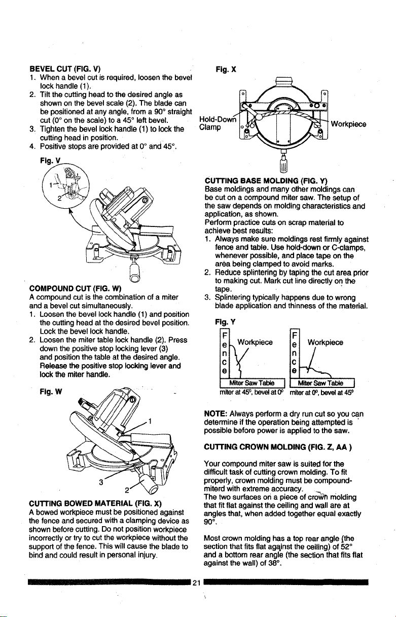
BEVELCUT(FIG.V)
1. When a bevel cutis required,loosenthe bevel
lockhandle (1).
2. Tilt the cuttinghead tothe desired angle as
shownon the bevel scale (2), The blade can
be positionedat any angle,from a 90° straight
cut (0°on the scale)to a 45° left bevel.
3. Tightenthe bevellockhandle (1) to lockthe
cuttinghead in position.
4. Positivestopsare providedat 0° and 45°.
Fig.
COMPOUND CUT (FIG. W)
A compoundcut is the combinationof a miter
and a bevelcut simultaneously.
1. Loosenthe bevellock handle (1) and position
the cuttinghead at thedesired bevelposition.
Lockthe bevellockhandle.
2. Loosenthe mitertable lockhandle (2). Press
downthe positivestoplockinglever (3)
and positionthetable at the desiredangle.
Release the positivestoplocking leverand
lockthe miterhandle.
Fig. W "
1
CUTTING BOWED MATERIAL (FIG. X)
A bowed workpiece must be positioned against
the fence and secured with a clamping device as
shown before cutting. Do not position workpiece
incorrectly or try to cut the workpiece without the
support of the fence. This will cause the blade to
bind and could result in personal injury.
I II!1111IHIIII
Fig. X
Hold-Dow_
Clamp _ Workpi_
CUTTING BASE MOLDING (FIG. Y)
Base moldingsand many othermoldingscan
be cut on a compoundmitersaw. The setup of
the saw dependson moldingcharacteristicsand
application,as shown.
Performpractice cutson scrap materialto
achieve best results:
1. Always make suremoldingsrestfirmly against
fence and table. Use hold-downor C-clamps,
whenever possible,and place tape on the
area being clamped to avoidmarks.
2. Reduce splinteringbytapingthe cut area prior
to making cut. Mark cut linedirectlyon the
tape.
3. Splinteringtypicallyhappensdue to wrong
blade applicationand thinness of the material.
Fig. Y
Workpiece
e
MiterSawTable I MiterSaw Table I
m_r at 45°, beret at 0° miter at 0o,bevelat 45o
NOTE: Alwaysperform a dryrun cut so you can
determine ifthe operationbeing attempted is
possible before powerisapplied to the saw.
CUTTING CROWN MOLDING (FIG. Z, AA )
Your compoundmiter saw is suitedfor the
difficulttask of cuttingcrown molding.To fit
propedy, crown moldingmustbe compound-
miterd withextreme accuracy. __ .
The two surfacesor1a piece of crowT_molding
that fitflat against the ceilingand wall are at
angles that,when added togetherequal exactly
90 ° ,
Most crown molding has a top rear angle [the
section that fits flat against the ceiling) of 52 °
and a bottom rear angle (the section that fits fiat
against the wall) of 38 °.
21 IIIIIIIIIIIII
IIIIII
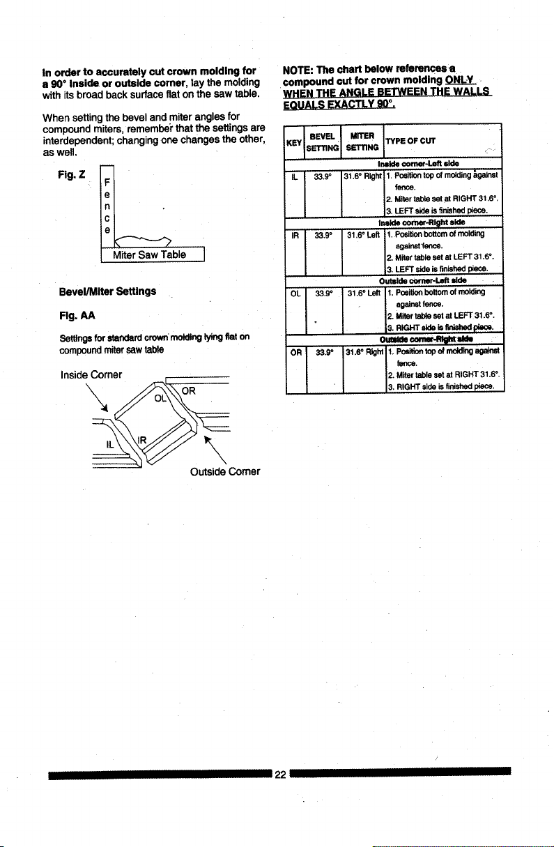
In order to accurately cut crown molding for
a 90°Inside or outside corner, lay the molding
withitsbroad back surfaceflat on the saw table.
When settingthe beveland miteranglesfor
compoundmiters, rememberthatthe settingsare
interdependent;changingone changes the other,
aswell.
Fig. Z
_ble I
Bevel/Miter Settings
Rg. AA
Settings for standardcrown moldinglyingflaton
compound miter saw table
InsideCorner
OutsideComer
NOTE:The chart below references a
compound cut for crown molding ONLY
WHEN THE ANGLE BETWEEN THE WALLS
EQUALS EXACTLY 90°.
I BEVEL I MITER
SETTING TYPE OF CUT
IL 33.9° 31.6 ° Right 1. Position topof molding_gatnst
fence.
2. Miter table setat RIGHT 31,6 °,
3. LEFT side isfinished piece.
IR 33,9° 31,6 ° Left 1, Position bottomof molding
ngalost 1enos,
2. Miter table setat LEFT 31.6 °,
3, LEFT side isfinished piece.
Outside €omer-L_t side
O!_ 33.9° 31,6 ° Left 1. Position bottom of molding
against fence.
2. Miter table set at LEFT 31.6 °.
OR 33.9° 31,So R_ht 1. Positiontop of mddldg against
fence.
2. Miter table setat RIGHT 31.6° ,
L RIGHT side isfinished piece.
I 22
MAINTENANCE
A DANGER I
To avoid injury, never put lubricants on the
blade while it is spinning.
WARNING I
To avoid fire or toxic reaction, never usa
gasoline, naphtha acetone, lacquer thinner or
similar highly volatile solvents to clean the
miter saw.
!_ WARNING
To avoid injury from unexpected starting
or electrical shock, unplug the power cord
before workin9 on the saw.
I_ WARNING I
For your safety, this saw is doubis-insulsted.
To avoid electrical shock, fire or Injury, use
only parts identical to those identified in the
parts list. Reassemble exactly as the original
assembly to avoid electrical shock.
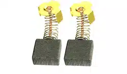
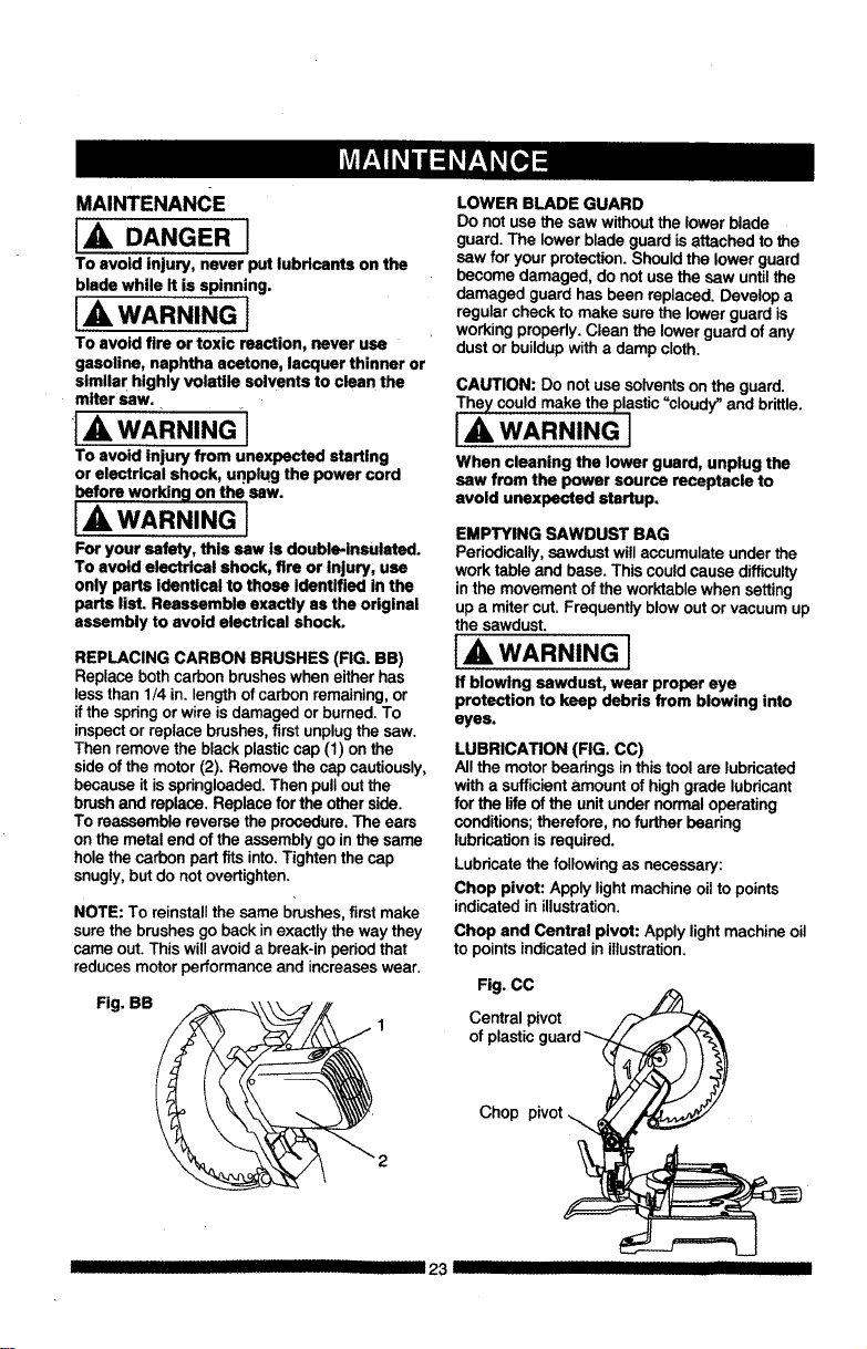
REPLACING CARBON BRUSHES (FIG. BB)
Replace both carbon brushes when either has
less than 1/4 in. length of carbon remaining, or
if the spring or wire is damaged or burned. To
inspect or replace brushes, first unplug the saw.
Then remove the black plastic cap (1) on the
side of the motor (2). Remove the cap cautiously,
because it is springloaded. Then pull out the
brush and replace. Replace for the other side.
To reassemble reverse the procedure, The ears
on the metal end of the assembly go in the same
hole the carbon part fits into, Tighten the cap
snugly, but do not overtighten.
NOTE: To reinstallthe same brushes,first make
surethe brushes go backin exactlythe way they
came out.This willavoid a break-inperiodthat
reducesmotorperformance and increaseswear.
Fig. BB
LOWER BLADE GUARD
Do notuse the saw withoutthe lower blade
guard. The lower blade guardisattachedto the
saw for yourprotection.Should the lowerguard
become damaged, do notuse the saw untilthe
damaged guard has been replaced.Develop a
regularcheckto make sure the lowerguard is
workingpropedy.Clean the lower guard of any
dustor buildupwitha damp cloth.
CAUTION: Do notuse solventsonthe guard.
The)/could make the plastic"cloudy_and brittle.
I,A WARNING I
When cleaning the lower guard, unplug the
saw from the power source receptacle to
avoid unexpected startup.
EMPTYING SAWDUST BAG
Periodically,sawdust willaccumulate under the
work table and base. This couldcause difficulty
inthe movementof the worktablewhen setting
up a miter cut. Frequently blowoutor vacuum up
the sawdust.
IA WARNING I
If blowing sawdust, wear proper eye
protection to keep debris from blowing into
eyes.
LUBRICATION (FIG. CC)
Allthe motorbearingsin thistool are lubdcated
witha sufficientamount ofhighgrade lubricant
for the life of the unitunder normal operating
conditions;therefore, no furtherbearing
lubricationisrequired.
Lubricatethe followingas necessary:
Chop pivot: Apply lightmachineoil to points
indicatedin illustration.
Chop and Central pivot: Applylight machine oil
to pointsindicated in illustration.
Fig. CC
Central pivot
of plastic,
Chop pivot
III 23 III
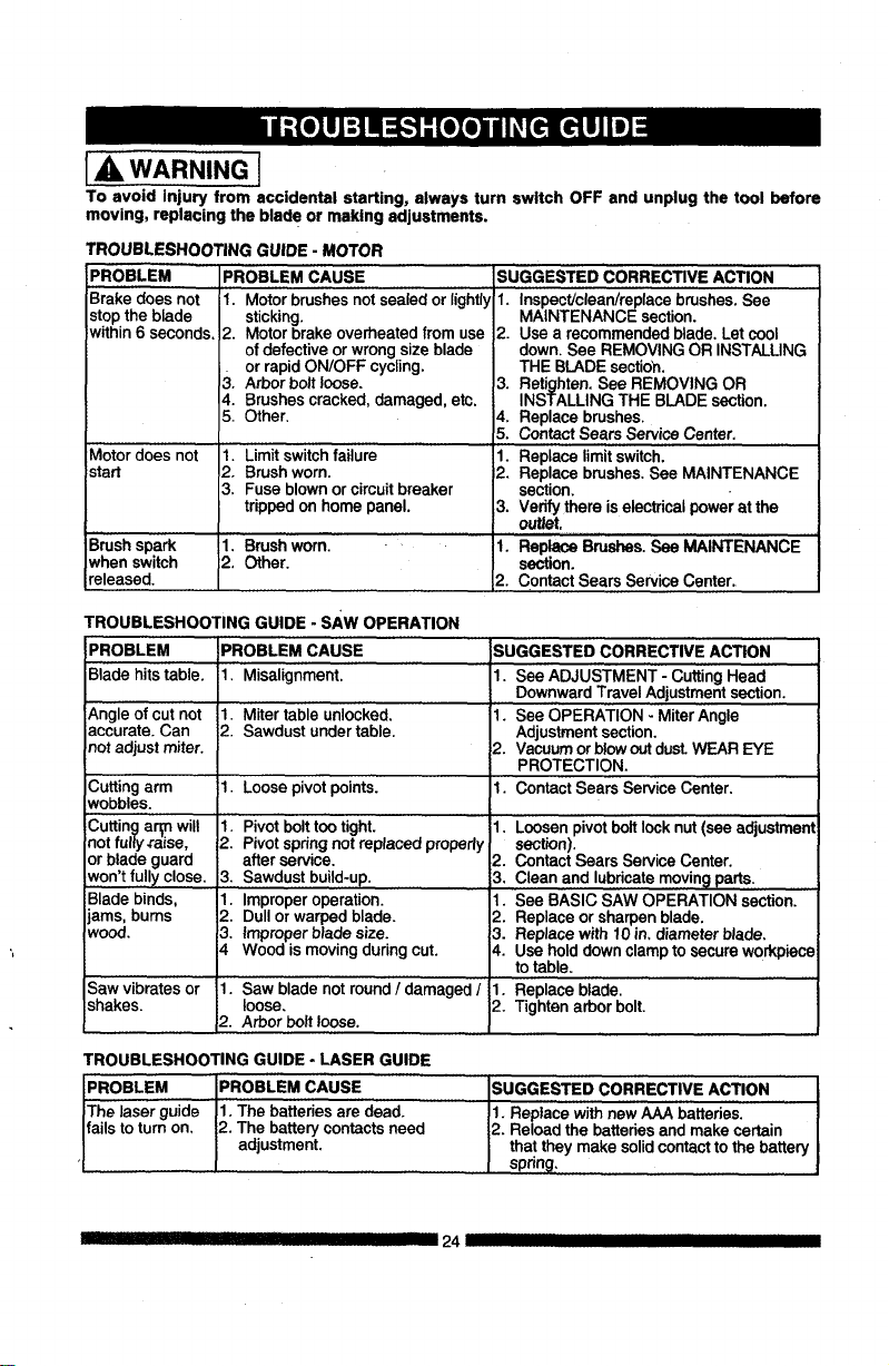
[_ WARNING]
To avoid injury from accidental starting, always turn switch OFF and unplug the tool before
moving, replacing the blade or making adjustments,
TROUBLESHOOTING GUIDE - MOTOR
PROBLEM PROBLEM CAUSE
Brake does not
stopthe blade
within6 seconds.
Motor does not
start
B,rushspark
whenswitch
released.
1. Motorbrushesnotsealed or lightly
sticking.
2. Motor brakeoverheatedfrom use
of defectiveorwrongsize blade
orrapidON/OFF cycling.
3. Arborbolt loose.
4. Brushescracked, damaged,etc.
5. Other.
1. Limit switchfailure
2. Brushworn.
3. Fuse blown orcircuitbreaker
trippedon home panel.
1. Brushworn.
2. Other.
SUGGESTED CORRECTIVE ACTION
1. Inspect/clean/replacebrushes.See
MAINTENANCE section.
2. Use a recommendedblade. Let cool
down,See REMOVINGOR INSTALUNG
THE BLADEsectioh.
3. Retighten.See REMOVING OR
INSTALLING THE BLADEsection.
4. Replacebrushes.
5. ContactSears ServiceCenter.
1. Replacelimitswitch.
2. Replacebrushes.See MAINTENANCE
section.
3. Vedfy there iselectricalpower at the
outlet,
1. ReplaceBrushes.See MAINTENANCE
section.
2. ContactSears ServiceCenter.
TROUBLESHOOTING GUIDE - sAw OPERATION
PROBLEM
Biadehitstable.
_,ngle of cut not
accurate. Can
not adjust miter.
ICutting arm
Nobbles.
Cutting ar_n will
=notfully #aise,
or blade guard
iwon't fully close.
Blade binds,
ams, bums
wood.
Saw vibrates or
shakes.
PROBLEM CAUSE
il Misalignment.
1. Miter table unlocked.
i2. Sawdust under table.
il. Loose pivot points.
1, Pivotbolttootight.
2. Pivotspringnotreplacedproperly
after service.
3. Sawdustbuild-up.
1. Improperoperation.
2. Dullor warpedblade.
3. Improperblade size.
4 Wood is moving during cut.
1. Saw bladenot round / damaged /
loose,
2. Arbor Ix)it loose.
SUGGESTED CORRECTIVE ACTION
1. See ADJUSTMENT - CuttingHead
DownwardTravelAdjustmentsection.
1. See OPERATION - MiterAngle
Adjustmentsection,
2. Vacuumorblowoutdust.WEAR EYE
PROTECTION.
1. ContactSears ServiceCenter,
1. Loosenpivotboltlock nut (see adjustment
section).
2. Contact Sears ServiceCenter.
3, Clean and lubricaternovin9 parts.
1. See BASIC SAW OPERATION section.
2. Replaceor sharpenblade.
3. Replacewith 10in, diameterblade,
4. Use holddownclampto secure workpiece
to table.
1. Replaceblade.
2. Tightenarborbolt.
TROUBLESHOOTING GUIDE - LASER GUIDE
PROBLEM PROBLEM CAUSE
The laser guide 1. The batteriesare dead.
fails to turn on, 2. The batterycontactsneed
adjustment.
SUGGESTED CORRECTIVE ACTION
1. Replace with new AAA batteries.
2. Reload the batteries and make certain
that they make solid contact to the battery
spring.
IIIill IIIII!1111 I III 24 II IIII
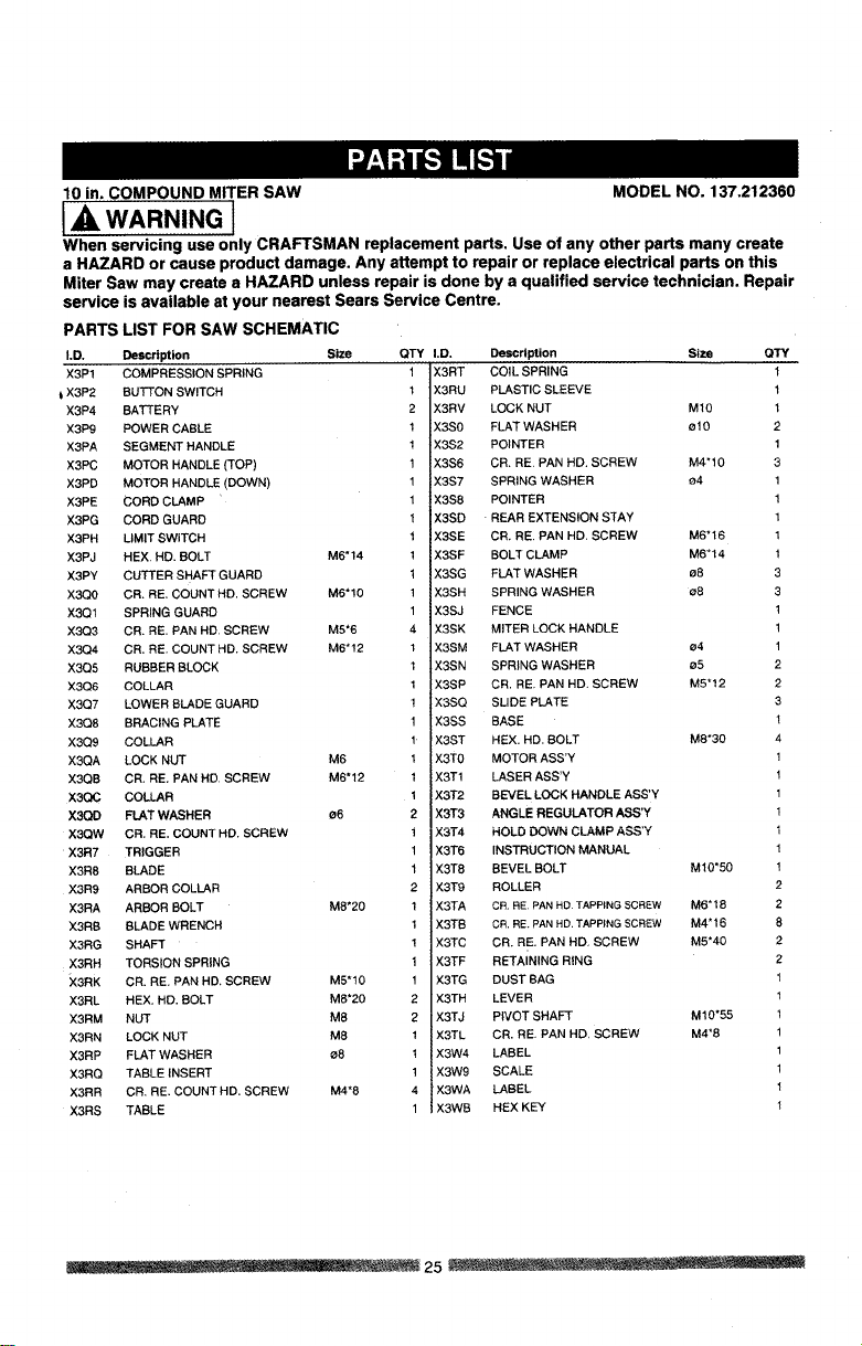
10 in. COMPOUND MITER SAW MODEL NO. 137.212360
ill WARNING l
When servicing use only CRAFTSMAN replacement parts. Use of any other parts many create
a HAZARD or cause product damage. Any attempt to repair or replace electrical parts on this
Miter Saw may create a HAZARD unless repair is done by a qualified service technician. Repair
service
PARTS LIST FOR SAW SCHEMATIC
LD. Description Size QTY
X3P1 COMPRESSION SPRING 1
t X3P2 BUTTON SWITCH 1
X3P4 BATTERY 2
X3P9 POWER CABLE 1
X3PA SEGMENT HANDLE 1
X3PC MOTOR HANDLE (TOP) 1
X3PD MOTOR HANDLE (DOWN) 1
X3PE CORD CLAMP 1
X3PG CORD GUARD 1
X3PH LIMIT SWITCH 1
X3PJ HEX, HD. BOLT M6"14 1
X3PY CUTTER SHAFT GUARD 1
X3Q0 CR. RE. COUNT HD. SCREW M6"10 1
X3QI SPRING GUARD 1
X:3Q3 CR. RE. PAN HD. SCREW M5"6 4
X3Q4 CR. RE. COUNT HD. SCREW M6"12 1
X3Q5 RUBBER BLOCK 1
X3Q6 COLLAR 1
X3Q7 LOWER BLADE GUARD !
X3Q8 BRACING PLATE 1
X3Q9 COLLAR 1
X3QA LOCK NUT M6 1
X3QB CR, RE. PAN HD. SCREW M6"12 1
X3OC COLLAR 1
X3QD FLAT WASHER s6 2
XSQW CR. RE, COUNT HD. SCREW i
X3R7 TRIGGER 1
X3R8 BLADE 1
X3R9 ARBOR COLLAR 2
X3RA ARBOR BOLT M8"20 1
X3RB BLADE WRENCH 1
X3RG SHAFT !
X3RH TORSION SPRING 1
X3RK CR. RE. PAN HD. SCREW M5"10 1
X3RL HEX. HD. BOLT M8"20 2
X3RM NUT M8 2
X3RN LOCK NUT M8 1
X3RP FLAT WASHER s8 !
X3RQ TABLE INSERT 1
X3RR CR, RE. COUNT HD, SCREW M4"8 4
X3RS TABLE 1
is available at your nearest Sears Service Centre.
I.D. Description Slze QTY
X3RT COIL SPRING 1
X3RU PLASTIC SLEEVE 1
X3RV LOCK NUT M10 1
X3S0 FLAT WASHER ¢10 2
X3S2 POINTER 1
X3S6 CR, RE PAN HD. SCREW M4"10 3
X3S7 SPRING WASHER 04 1
X3S8 POINTER 1
X3SD REAR EXTENSION STAY 1
X3SE CR. RE. PAN HD, SCREW M6"16 1
X3SF BOLT CLAMP M6"14 1
X3$G FLAT WASHER 08 3
X3SH SPRING WASHER s8 3
X3SJ FENCE 1
X3SK MITER LOCK HANDLE 1
X3SM FLAT WASHER 04 1
X3SN SPRING WASHER 05 2
X3SP CR. RE, PAN HD, SCREW M5"12 2
X3SQ SLIDE PLATE 3
X3SS BASE 1
X3ST HEX. HD. BOLT M8"30 4
X3T0 MOTOR ASS'Y 1
X3T1 LASER ASS'Y 1
X3T2 BEVEL LOCK HANDLE ASS'Y 1
X3T3 ANGLE REGULATOR ASS'Y 1
X3T4 HOLD DOWN CLAMP ASS'Y I
X3T6 INSTRUCTION MANUAL 1
X3T8 BEVEL BOLT M10"50 1
X3T9 ROLLER 2
X3TA CR. RE PAN HD TAPPING SCREW M6"18 2
X3TB CR. RE, PAN HD. TAPPING SCREW M4"16 8
X3TC CR. RE. PAN HD, SCREW M5"40 2
X3TF RETAINING RING 2
X3TG DUST BAG 1
X3TH LEVER 1
X3TJ PIVOT SHAFT M10"55 1
X3TL CR. RE, PAN HD, SCREW M4"8 1
X3W4 LABEL 1
X3W9 SCALE 1
X3WA LABEL 1
X3WB HEX KEY 1
...... . ..... . _ 25 ..................
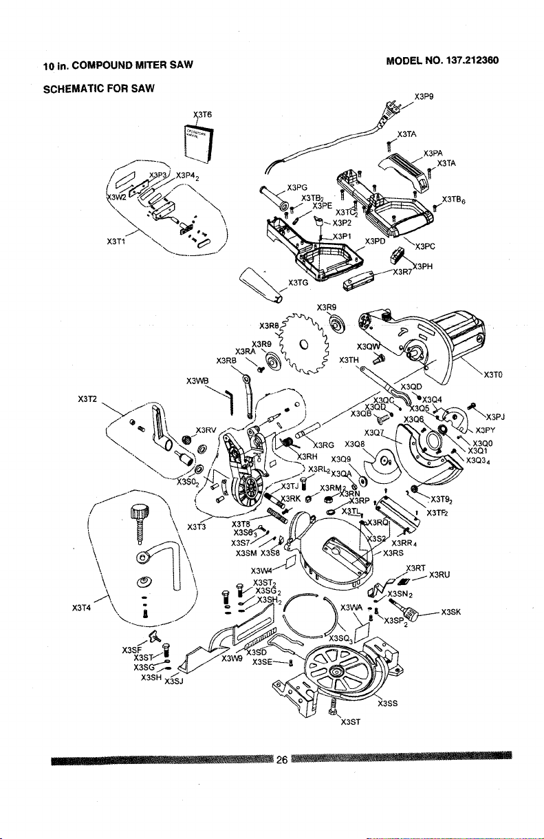
10 in. COMPOUND MITER SAW
SCHEMATIC FOR SAW
X3T1
MODEL NO, 137.212360
'\,
)
X3T2
X3WB
X3R9
X3RA
X3RB
(3TO
X3Q1
X3SM
X3SS
X3ST
X3T_
X3RR4
-X3RS
X3RT
..... 26 ......

10 in. COMPOUND MITER SAW
MODEL NO. 137.212360
PARTS LIST AND SCHEMATIC FOR MOTOR
I.D. Description Size OTY
X3P0 HEX.SOC. HD. CAP SCREW 1
X3PK LABEL 1
X3PL BRUSHHOLDER ASS'Y 2
X3PM BRUSHCOVER 2
X3PQ MOTOR HOUSING 1
I.D. Description Size
X3QJ LABEL
X3QK BRUSHASS'Y
X3QL FLOW GUIDE
X3QM CR. RE.PAN HD.TAPPING SCREW ST5"65
X3QN FIELDASS'Y
X3PR BEARING
X3PS SPRING
X3PT ARMATURE ASS'Y
X3PU , COMPRESSION SPRING
X3PV ARBOR LOCK
X3PW BEARING
X3PX ARM
X3PZ FLATWASHER
X3QE RUBBERINSERT
X3QF CAP
×3QG LABEL
X3QH LABEL
_6
I X3QU
I X3QR
I X3QS
I X3QY
I X3R3
I X3SB
I X3SN
4 X3TD
1 X3TE
I X3TM
1 X3WC
1
HEX.SOC. HD. CAP SCREW M6"25
HEX.SOC. HD. CAP SCREW
ANCHOR BLOCK
NEEDLEBEARING
CR. RE.PAN HD. SCREW M5"16
FLATWASHER _5
SPRING WASHER _5
CR. RE.PAN HD. SCREW M6"35
TOOTH WASHER e4.2
CR. RE.PAN HD. SCREW M4"10
CUTTERSHAFTASS'Y
OTY
1
2
]
2
I
i
I
I
I
2
2
4
4
I
I
I
X3QM
X3QK
_/X3PK
X3PQ_
X3PL2
X3PR _ _ X3PM2
X3PS '%3pz_X3TD4
X3SN
IIIIIIIIIII27 IIII I III IIIIIII

Congratu/ations on making a smartpurchase. Your new Craftsman_ productisdesigned and
manufactured for years of dependable operation. But like all products, it may require repair
from time to time. That's when having a Repair Protection Agreementcan save you money and
aggravation.
Here's what the Repair Protection Agreement* includes:
[] Expert service by our 10,000 professionalrepairspecialists
[] Unlimited service and no charge for parts and laboron allcoveredrepairs
[] Product replacement up to$1500 if your coveredproductcan'tbe fixed
[] Discount of 10% from regular pdce ofserviceand relatedinstalledpartsnotcoveredby the
agreement;also, 10% offregularpriceof preventivemaintenance check
[] Fast help by phone - we call it RapidResolution- phonesupportfrom a Sears representative.
Thinkof us as a "talking owner'smanual."
Once you purchase the Repair ProtectionAgreement, a simplephonecall isall that ittakesfor you
to schedule service. You can callanytime day or night,or schedulea service appointmentonline.
The Repair ProtectionAgreement isa risk-free purchase.If youcancel for any reason dudngthe
productwarranty period, we will providea full refund. Or, aprorated refundanytimeafter
the productwarrantyperiod expires. Purchase yourRepairProtectionAgreementtodayl
Some limitations and exclusions apply. For prices and additional information in the U.S.A.
call 1-800-827-6655.
*Coverage in Canada varies on some items. For full details cell Sears Canada at
1-600-361-6665.
Sears Installation Service
For Sears professionalinstallationof home appliances, garagedoor openers, water heaters,and
other major homeitems, inthe U.S.A. or Canada call1.600-4-MY-HOME _.
IIII '1 I III III I 28 IIIIIII

Your Home
For expert troubleshootingand home solutionsadvice:
manage home
www.managemyhome.com
For repair - in your home - of all major brand appliances,
lawn and garden equipment, or heating and cooling systems,
no matter who made it, no matter who sold ,t!
For the replacement parts, accessories and
owner's manuals that you need to do-it-yourself.
For Sears professional installation of home appliances
and items like garage door openers and water heaters.
1-800-4-MY-HOME® Call anytime, day or night
(1-800-469-4663) (U.S.A. and Canada)
www.sears.com www.sears.ca
Our Home
For repair of carry-in items like vacuums, lawn equipment,
and electronics, call anytime for the location ofthe nearest
Sears Parts & Repair Service Center
1-800-488-1222 (U.S.A.) 1-800-469-4663 (Canada)
www.sears.com www.sears.ca
To purchase a protection agreement on a product serviced by Sears:
1-800-827-6655 (U.S.A.) 1-800-361-6665 (Canada)
Para pedir servicio de reparaci6n Au Canada pour service en franc_.ais:
a domicilio,y para ordenar piezas: 1-800-LE-FOYER Mc
1-888-SU-HOGAR_ (1-800-533-6937)
(1-888-784-6427) www.sears.ca
oSears
©Sears Brands, LLC
® Registered Trademark / TM Trademark / sM Service Mark of Sears Brands, LLC
® Marca Registrada / TM Marca de Fdbrica / sMMarca de Servicio de Sears Brands, LLC
_c Marque de commerce / _ Marque d(_posee de Sears Brands, LLC