Loading ...
Loading ...
Loading ...
• Ifsituationsoccurwhicharenotcov-
ered in this manual, use care and
goodjudgment. If you need assis-
tance,call 1-800-235-5878.
SPECIAL NOTICE: This unit is not
equipped with a temperature limiting
muffler and spark arresting screen
which meets the requirements of Cali-
fornia Codes 4442 and 4443. All U.S.
forest land and the states of California,
Idaho, Maine, Minnesota, New Jersey,
Oregon, and Washington require by
law that many internal combustion en-
gines be equipped with a spark arres-
tor screen. If you operate in a locale
where such regulations exist, you are
legally responsible for installing and
maintaining the operating condition of
these parts. Failure to do so is a viola-
tion of the law. Refer to the MAINTE-
NANCE section in this manual.
SPECIAL NOTICE: Exposure to
vibrations through prolonged use of
gasoline powered hand tools could
cause blood vessel or nerve damage
in the fingers, hands, and joints of
people prone to circulation disorders
or abnormal swellings. Prolonged use
in cold weather has been linked to
blood vessel damage in otherwise
healthy people. If symptoms occur
such as numbness, pain, loss of
strength, change in skin color or tex-
ture, or loss of feeling in the fingers,
hands, or joints, discontinue the use of
this tool and seek medical attention.
An anti-vibration system does not
guarantee the avoidance of these
problems. Users who operate power
tools on a continual and regular basis
must monitor closely their physical
condition and the condition of this tool.
CARTON CONTENTS
Check carton contents against the fol-
lowing list.
Model 358.796200
• Trimmer
• Shield
• 2-cycle engine oil
Examine parts for damage. Do not
use damaged parts.
NOTE: If you need assistance or find
parts missing or damaged, call
1-800-235-5878.
It is normal for the fuel filter to rattle in
the empty fuel tank.
Finding fuel or oil residue on muffler is
normal due to carburetor adjustments
and testing done by the manufacturer.
ASSEMBLY
z't
dBLWARNING: If received as-
sembled, repeat all steps to ensure
your unit is properly assembled and all
fasteners are secure.
ADJUSTING THE HANDLE
_tLWARNING: When adjusting the
handle, be sure it remains between
the trigger and the safety label.
• Loosen wing nut or knob on handle.
• Rotate the handle on the tube to an
upright position; retighten wing nut.
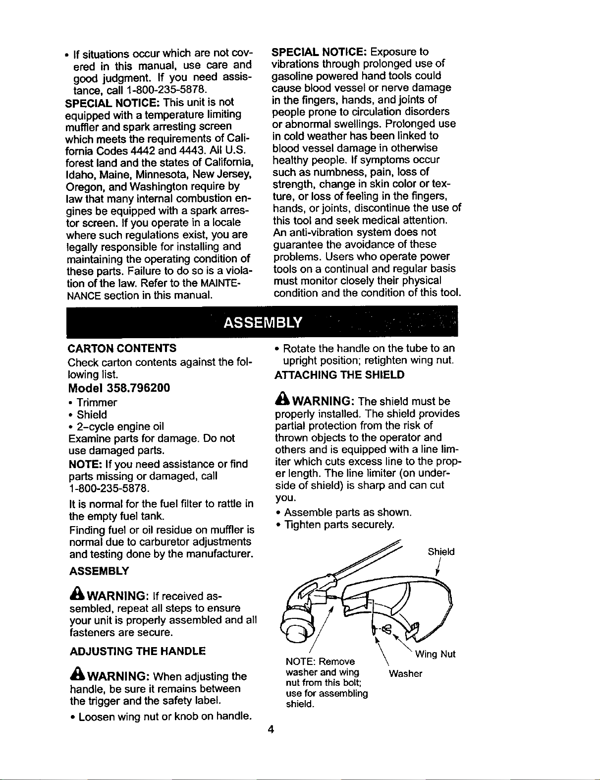
ATTACHING THE SHIELD
_ILWARNING: The shield must be
properly installed. The shield provides
partial protection from the risk of
thrown objects to the operator and
others and is equipped with a line lim-
iter which cuts excess line to the prop-
er length. The line limiter (on under-
side of shield) is sharp and can cut
you.
• Assemble parts as shown.
• Tighten parts securely.
S Siel d
NOTE: Remove _k Wing Nut
washer and wing Washer
nut from this bolt;
use for assembling
shield.
4
Loading ...
Loading ...
Loading ...