Loading ...
Loading ...
Loading ...
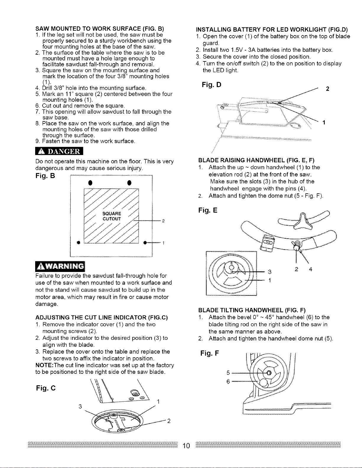
SAW MOUNTED TO WORK SURFACE (FIG. B)
1. If the leg set will not be used, the saw must be
properly secured to a sturdy workbench using the
four mounting holes at the base of the saw.
2. The surface of the table where the saw is to be
mounted must have a hole large enough to
facilitate sawdust fall-through and removal.
3. Square the saw on the mounting surface and
mark the location of the four 3/8" mounting holes
(1).
4. Drill 3/8" hole into the mounting surface.
5. Mark an 11" square (2) centered between the four
mounting holes (1).
6. Cut out and remove the square.
7. This opening will allow sawdust to fall through the
saw base.
8. Place the saw on the work surface, and align the
mounting holes of the saw with those drilled
through the surface.
9. Fasten the saw to the work surface.
Do not operate this machine on the floor. This is very
dangerous and may cause serious injury.
Fig. B
2
INSTALLING BATTERY FOR LED WORKLIGHT (FIG.D)
1. Open the cover (1) of the battery box on the top of blade
guard.
2. Install two 1.5V - 3A batteries into the battery box.
3. Secure the cover into the closed position.
4. Turn the on/off switch (2) to the on position to display
the LED light.
Fig. D
/
BLADE RAISING HANDWHEEL (FIG. E, F)
1. Attach the up ~ down handwheel (1) to the
elevation rod (2) at the front of the saw.
Make sure the slots (3) in the hub of the
handwheel engage with the pins (4).
2. Attach and tighten the dome nut (5 - Fig. F).
Fig. E
Failure to provide the sawdust fall-through hole for
use of the saw when mounted to a work surface and
not the stand will cause sawdust to build up in the
motor area, which may result in fire or cause motor
damage.
ADJUSTING THE CUT LINE INDICATOR (FIG.C)
1. Remove the indicator cover (1) and the two
mounting screws (2).
2. Adjust the indicator to the desired position (3) to
align with the blade.
3. Replace the cover onto the table and replace the
two screws to affix the indicator in position.
NOTE:The cut line indicator was set up at the factory
to be positioned to the right side of the saw blade.
Fig. C
1
2
10
3 2 4
1
BLADE TILTING HANDWHEEL (FIG. F)
1. Attach the bevel 0° ~ 45 ° handwheel (6) to the
blade tilting rod on the right side of the saw in
the same manner as above.
2. Attach and tighten the handwheel dome nut (5).
Fig. F
Loading ...
Loading ...
Loading ...