
Installation Guide
Quality, Design and Innovation
home.liebherr.com/fridge-manuals

Contents
1 General safety instructions................................... 2
2 Installation conditions........................................... 2
2.1 Location.................................................................... 2
2.2 Installing multiple appliances.................................... 2
2.3 Mains connection..................................................... 3
3 Appliance dimensions........................................... 3
4 Recess dimensions............................................... 4
4.1 Internal dimensions.................................................. 4
5 Ventilation requirements....................................... 4
6 Transporting the appliance................................... 5
7 Unpacking the appliance...................................... 5
8 Setting up the appliance....................................... 5
8.1 After installation........................................................ 5
9 Disposing of packaging........................................ 5
10 What the symbols mean........................................ 5
11 **** freezer compartment door.............................. 6
11.1 Moving the door hinge.............................................. 6
12 Reversing the door................................................ 7
13 Connecting the water supply................................ 8
14 Installing the appliance in the recess.................. 9
15 Cabinet fronts......................................................... 16
15.1 Dimensions.............................................................. 16
15.2 Mounting the cabinet front(s).................................... 16
15.3 Setting the clearance to avoid collision..................... 17
16 Water tank............................................................... 17
16.1 Inserting the water tank............................................ 17
17 Connecting the appliance..................................... 17
The manufacturer works constantly on the further development
of all the types and models. Therefore please understand that
we have to reserve the right to make design, equipment and
technical modifications.
To get to know all the benefits of your new appliance, please
read the information contained in these instructions carefully.
The instructions apply to several models. Differences may
occur. Text relating only to specific appliances is marked with
an asterisk (*).
Instructions are marked with a , and results are marked
with a
.
1 General safety instructions
-
Only install, connect and dispose of the appli-
ance according to the instructions.
-
The socket must be easily accessible so that
the appliance can be quickly disconnected
from the supply in an emergency. It must be
outside the area of the rear of the appliance.
DANGER identifies a situation involving direct
danger which, if not obviated, may
result in death or severe bodily
injury.
WARNING identifies a dangerous situation
which, if not obviated, may result in
death or severe bodily injury.
CAUTION identifies a dangerous situation
which, if not obviated, may result in
minor or medium bodily injury.
NOTICE identifies a dangerous situation
which, if not obviated, may result in
damage to property.
Note identifies useful information and tips.
2 Installation conditions
WARNING
Fire hazard due to dampness!
If live parts or the mains lead become damp this may cause
short circuits.
u
The appliance is designed for use in enclosed areas. Do
not operate the appliance outdoors or in areas where it is
exposed to splash water or damp conditions.
Intended use
-
Install and use the appliance in indoor spaces only.
-
Use the appliance only once installed.
2.1 Location
WARNING
Fire hazard due to refrigerant!
The coolant used is eco-friendly but also flammable. Any
leaking coolant may ignite.
u
Do not damage the piping of the refrigeration circuit.
-
If the appliance is installed in a very humid environment,
condensation can build up on the outside of the unit.
Always make sure the installation location is well ventilated .
-
The more coolant there is in the appliance, the larger the
room in which the appliance is installed must be. If the room
is too small, any leak may create a flammable mixture of gas
and air. For each 8 g of coolant the installation space must
be at least 1 m
3
. Information on the coolant is on the model
plate inside the appliance.
2.1.1 Supporting floor
-
The floor of the installation site must be horizontal and even.
-
If the floor is not entirely even, the kitchen cabinet housing
the appliance must be levelled with support blocks.
2.1.2 Positioning
-
Do not install the appliance in direct sunlight, next to an
oven, radiator or similar.
-
Only fit the appliance into solid kitchen units.
2.2 Installing multiple appliances
NOTICE
Risk of damage due to condensate!
u
Do not install the appliance directly alongside a further
refrigerator/freezer.
NOTICE
Risk of damage due to condensation!
u
Do not install the appliance directly above another refriger-
ator or freezer.
General safety instructions
2 * Depending on model and options

These appliances are designed for a variety of installation
options. Combine appliances only if the appliance is suitable.
The following table shows the installation options by model:
Installation
option
Model
Single All models
Side-by-side
(SBS)
Model names starting with S....
See the supplied SBS installation guide for
the correct positioning.
Stacked Models with a maximum recess height of
880 mm and with a heated cover can be
“stacked”.
Top appliance: up to a maximum recess
height of 140 mm
Fig. 1
Build each appliance into a separate recess.
2.3 Mains connection
WARNING
Risk of fire due to short circuit!
If the mains cable/connector of the appliance or of another
appliance touch the rear of the appliance, the mains cable/
connector may be damaged by the appliance vibrations,
leading to a short circuit.
u
Stand the appliance so that it is not touched by connectors
or main cables.
u
Do not plug the appliance or any others into sockets located
near the rear of the appliance.
3 Appliance dimensions
Fig. 2
A
(mm)
B
(mm)
C
(mm)
D
(mm)
E
(mm)
ICB/b/c/i/d/ 51..
559 546 1770
549
15
IC/e/d51.. /
S/ICN/f/d/e/i51.. /
ICBN/c/e/I/d/51..
695
Fig. 3
Appliance dimensions
* Depending on model and options 3
A (mm) B (mm) C (mm)
IFNe 35..
559 546
712
IR/f/e/d/c39..
SIBa 39../IFN/e/
d39..
872
IRe40../
IRBd40..
1022
IR/e/
d41../IRB/b/d/
i41../SIFNd 41..
1213
IRe45../
IRBd45../SIFNd
45..
1395
IRBe48.. 1572
IR/f/e51../
IRD/c/e/d/i/51.. /
IRBPdi51../
SIFn/f/h/e/i 51..
1770
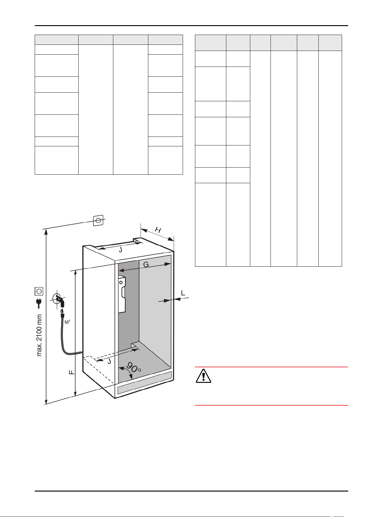
4 Recess dimensions
4.1 Internal dimensions
Fig. 4
*
M
1
): Only for IRBdi 5180/5190, ICNdi 5173, ICBNd/i
5163/73/83, ICBdi 5182*
F
(mm)*
G
(mm)*
H (mm)* J
(mm)*
L
(mm)*
IFNe 35..
714
-730
560 —
570
min. 550,
recom-
mended:
560
min.
500
max. 19
IR/f/e/d/
c39..
SIBa39../
IF/Se39../
IFNe/d 39..
874 —
890
IRe 40../
IRBd 40..
1024 —
1040
IR/e/d
41../IRB/b/
d/i 41.. /
SIFNd 41.
1216 —
1236
IRe 45../
IRBd 45.. /
SIFNd 45..
1397 —
1413
IRBe 48.. 1574 —
1590
IR/f/e 51../
IRD/c/e/d/i/
51.. /
IC/e/d
51.. /
S/ICN/f/d/e
/i 51.. /
ICB/N/c/e/I
/d/ 51.. /
IRBPdi
51../
SIFN/Sf/e/
ei/h/hi/
1772 —
1788
The specified energy consumption applies to a unit depth of
560 mm. The appliance will work properly at a unit depth of 550
mm, but at a slightly higher energy consumption.
u
Check the wall thickness of adjacent cabinets: It must be
min. 16 mm.
u
Only fit the appliance into stable, solid kitchen units. Secure
the unit against tipping.
u
Align the cabinets with a spirit level and a try square.
If necessary level them by putting something underneath
them.
u
Ensure that the floor and the side panels of the cabinet are
at right angles to each other.
5 Ventilation requirements
WARNING
Blocked ventilation openings pose a risk of fire and damage!
u
Always keep the ventilation openings clear. Always ensure
that the appliance is properly ventilated!
Always follow the required ventilation gaps:
-
The depth of the ventilation shaft at the back of the cabinet
must be at least 38 mm.
-
At least 200 cm
2
is required for the ventilation gap cross
sections in the plinth and the housing cabinet.
-
As a rule, the bigger the ventilation space the more effi-
ciently the appliance can run.
Sufficient ventilation is required for the operation of the appli-
ance. The provided ventilation grids ensure an effective ventila-
tion gap on the appliance of 200 cm
2
. If you replace the ventila-
Recess dimensions
4 * Depending on model and options
tion grids with a panel this must have the same size or larger
ventilation gap than the grid provided by the manufacturer.
6 Transporting the appliance
u
Transport the appliance only in suitable packaging.
u
Transport the appliance upright.
u
Do not transport the appliance on your own.
7 Unpacking the appliance
Before you connect the appliance, report any damage immedi-
ately to the delivery company.
u
Check the appliance and the packaging for damage during
transport. Contact the supplier immediately if you suspect
any level of damage.
u
Remove all materials from the back or the side walls of the
appliance that may prevent proper installation or ventilation.
u
Remove all protective films from the appliance. Do not use
sharp or pointed objects for this.
u
Take the power cable from the rear of the appliance.
Remove the cable brackets when you do this, otherwise
there will be noise caused by vibrations!
8 Setting up the appliance
CAUTION
Risk of injury!
u
The appliance must be transported to its place of installation
by two people.
WARNING
Risk of tipping
u
The appliance must be fixed in accordance with the instruc-
tions in order to prevent a hazard caused by the instability of
the appliance.
WARNING
Fire hazard and danger of damage!
u
Do not place appliances emitting heat e.g. microwaves,
toasters etc. on the appliance!
If possible, have the appliance installed in the kitchen unit by a
professional.
Do not install the appliance on your own.
8.1 After installation
u
Remove all transport safety components.
Fig. 5
*
u
Remove the red transport
safety device.
u
Clean the appliance (see User Guide, Cleaning the appli-
ance).
9 Disposing of packaging
WARNING
Danger of suffocation due to packing material and plastic film!
u
Do not allow children to play with packing material.
The packaging is made of recyclable materials:
-
corrugated board/cardboard
-
expanded polystyrene parts
-
polythene bags and sheets
-
polypropylene straps
-
nailed wooden frame with polyethylene panel*
u
Take the packaging material to an official collecting point.
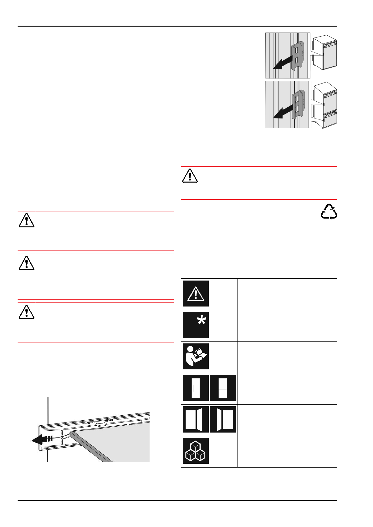
10 What the symbols mean
Risk of injury here! Follow the safety
notes!
These instructions apply to a range
of models. Follow this step only if it
applies to your appliance.
To install, please follow the detailed
description in the Guide.
This section applies either to a single-
door appliance or a double-door appli-
ance.
Choose one of the options: Appliance
with right-hinged door or appliance
with left-hinged door.
Installation step required if your model
has IceMaker and/or InfinitySpring.
Transporting the appliance
* Depending on model and options 5
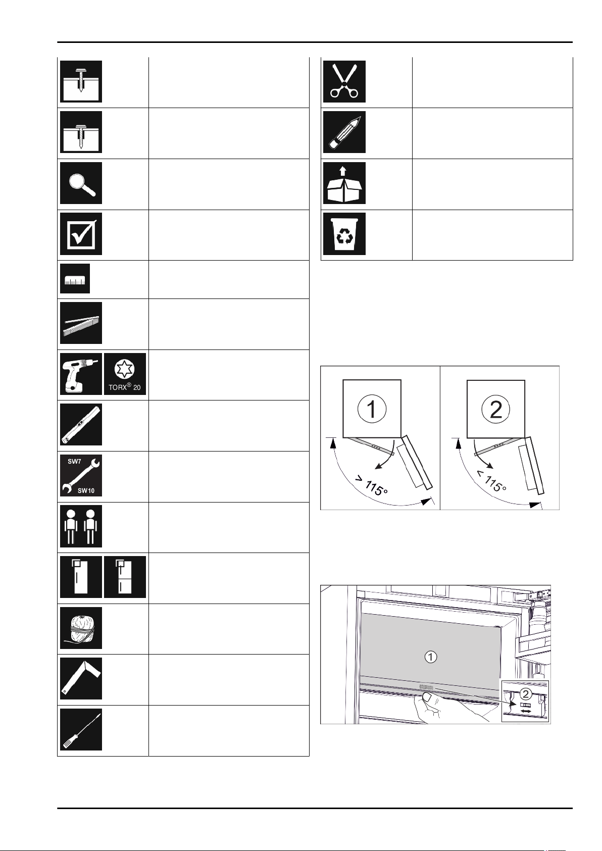
Just loosen the screws or tighten them
slightly.
Tighten the screws.
Check to see if the next step applies
for your model.
Check the correct assembly/seat of
the components used.
Measure the specified measurement
and adjust if necessary.
Tool for assembly: Metre rule
Tool for assembly: Cordless screw-
driver and attachments
Tool for assembly: Spirit level
Tool for assembly: Size 7 and size 10
spanners
Two people are required for this step.
Carry out this step at the marked place
on the appliance.
Aids for assembly: String
Aids for assembly: Square
Aids for assembly: Screwdriver
Aids for assembly: Scissors
Aids for assembly: Non-permanent
marker pen
Accessory kit: Remove components
Dispose of components that are no
longer needed.
11 **** freezer compartment door
The **** freezer compartment door can be easily moved when-
ever changing the door hinge. If the door of the refrigerator
can be opened more than 115° (1), the freezer compartment
can also be opened without changing the hinge. If the opening
angle (2) of the appliance door is less than this, the door hinge
must be repositioned.
Fig. 6
*
11.1 Moving the door hinge
The slider for moving the door hinge is located on the back of
the **** freezer compartment door at the bottom.
Fig. 7
u
Close the **** freezer compartment door (1).
u
Grab the **** freezer compartment door from below.
u
Slide the slider (2) either to the right or to the left.
**** freezer compartment door
6 * Depending on model and options
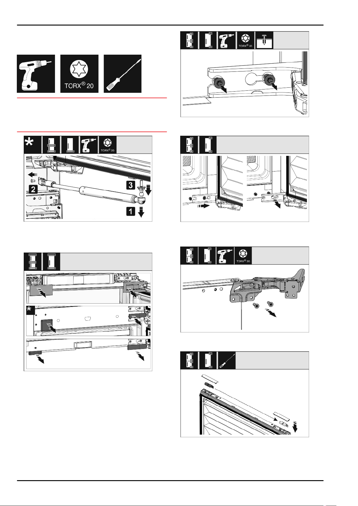
12 Reversing the door
Tool
Fig. 8
NOTICE
Live parts
Damage to electrical parts
u
Before changing the door hinge, disconnect the plug at the
mains.
Fig. 9
u
Removing the soft stop damper: Remove the soft stop
damper from the ball stud (1). Unscrew the retainer (2).
Remove the ball stud with a screwdriver (3).
Fig. 10
u
Remove covers.
Fig. 11
u
Loosen the screws on all hinges but do not remove them.
Fig. 12
*
u
Removing the door: Push the door forward and then out,
unhang it and put it to one side.
Fig. 13
u
Unscrew all hinges and set aside together with the screws.
Fig. 14
u
Loosen and shift the bracket at the top and bottom of the
door. The bracket must be shifted so you can screw on the
hinges.
Reversing the door
* Depending on model and options 7

Fig. 15
u
Shift the screws to fasten the hinge. Do not screw tightly
after shifting – you need to hang the hinges later.
Fig. 16
u
Move the fixing bracket to the opposite side.
Fig. 17
u
Turn all hinges 180° to the opposite side and screw firmly.
Fig. 18
*
u
Refitting the door: Hang the door with its hinges and tighten
the screws.
Fig. 19
u
Refitting the closing dampers: Screw in the ball studs (1),
tighten the bracket (2) and hang the closing dampers in the
ball studs.
u
Check all screws and retighten if necessary.
Fig. 20
u
Reassemble the bottom and centre cover. Only replace the
remaining covers after installing the appliance back into the
cabinet.
13 Connecting the water supply
Connecting the hose to the appliance
The solenoid valve is at the bottom on the back of the appli-
ance. It has a R3/4 connecting thread.
Fig. 21
Connecting the water supply
8 * Depending on model and options
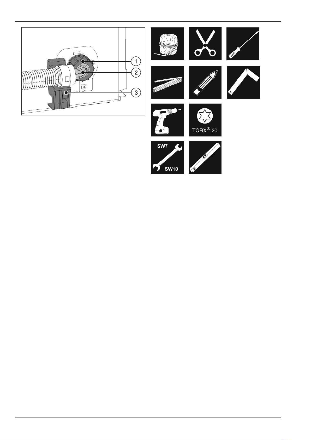
Fig. 22
u
Hold the angled hose end
Fig. 22 (2)
horizontally at bracket
Fig. 22 (3)
and secure it.
u
Screw the nut
Fig. 22 (1)
on by hand until it is firmly in place.
Connecting the hose to the stopcock
u
Connect the straight end of the hose
Fig. 21 (4)
to the stop-
cock
Fig. 21 (5)
.
Check the water system
u
Slowly open the stopcock.
Before putting into its final position:
u
Check the entire water system for tightness.
After installing in the recess:
u
Clean the IceMaker (see User Guide, Maintenance).
Air the water system
Airing is required in the following cases:
- Initial operation
- Replacement of the InfinitySpring water tank
Ensure that the following conditions are met:
- Appliance is properly installed and connected.
- Water tank is inserted (see Operating instructions, Mainte-
nance).
- Water filter is inserted (see Operating instructions, Mainte-
nance).
- Appliance is switched on.
u
Open the appliance door.
u
Press your drinking glass or cup against the lower part of the
InfinitySpring dispenser.
w
The top part moves out and air or water pours into the glass.
u
Continue until the water flows evenly into the glass.
w
There is no more air in the system.
u
InfinitySpring Cleaning (see the User Guide, Maintenance).
14 Installing the appliance in the
recess
Tool
Fig. 23
Supplied assembly parts
Installing the appliance in the recess
* Depending on model and options 9
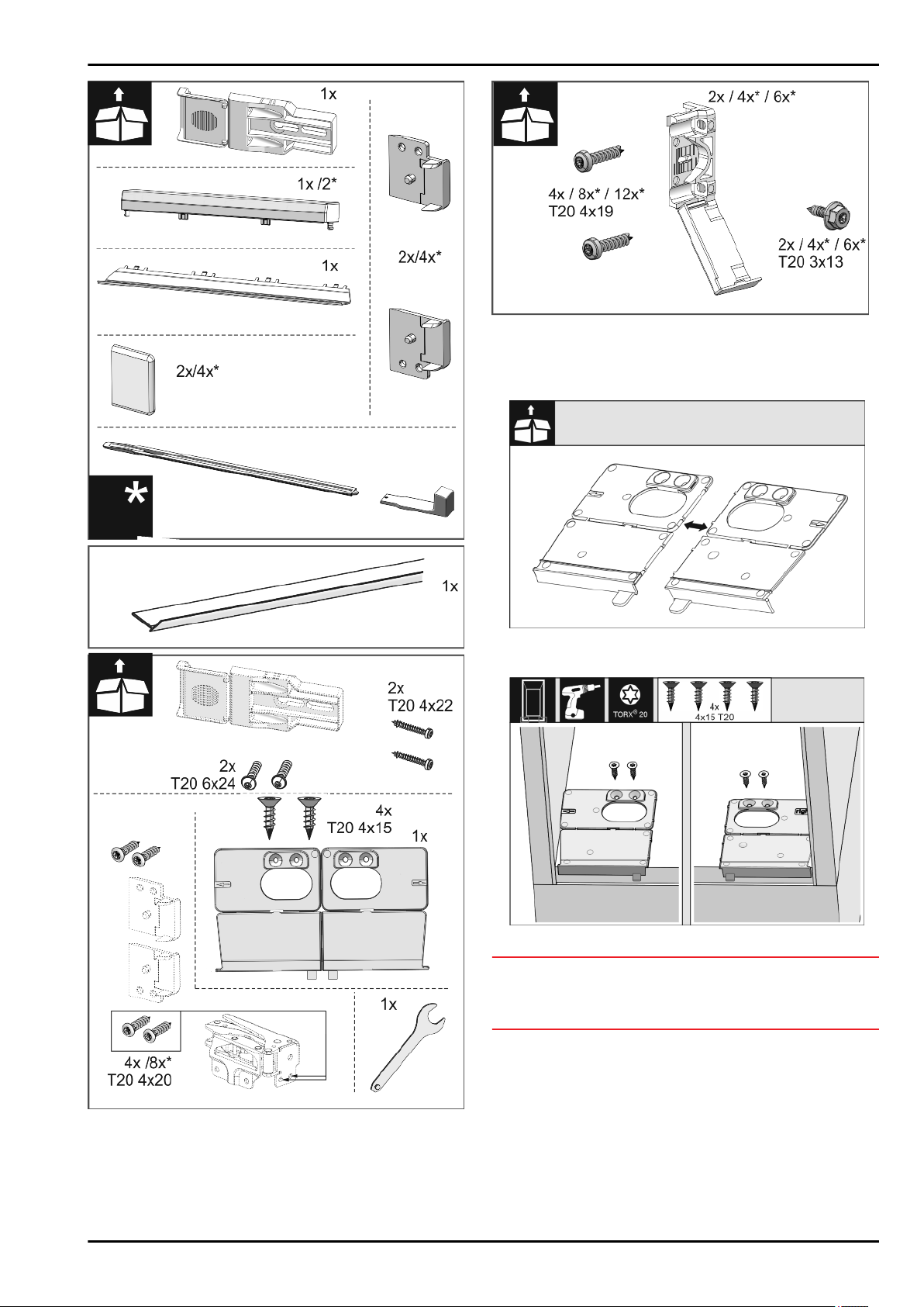
Fig. 24
Fig. 25
Fig. 26
u
Separate the mounting bracket at the perforation.
Fig. 27
NOTICE
Correct installation depth of the appliance.
u
Using the mounting bracket ensures the correct installation
depth of the appliance.
u
Screw the mounting brackets on the left and right of the
recess floor, flush to the side wall.
Installing the appliance in the recess
10 * Depending on model and options
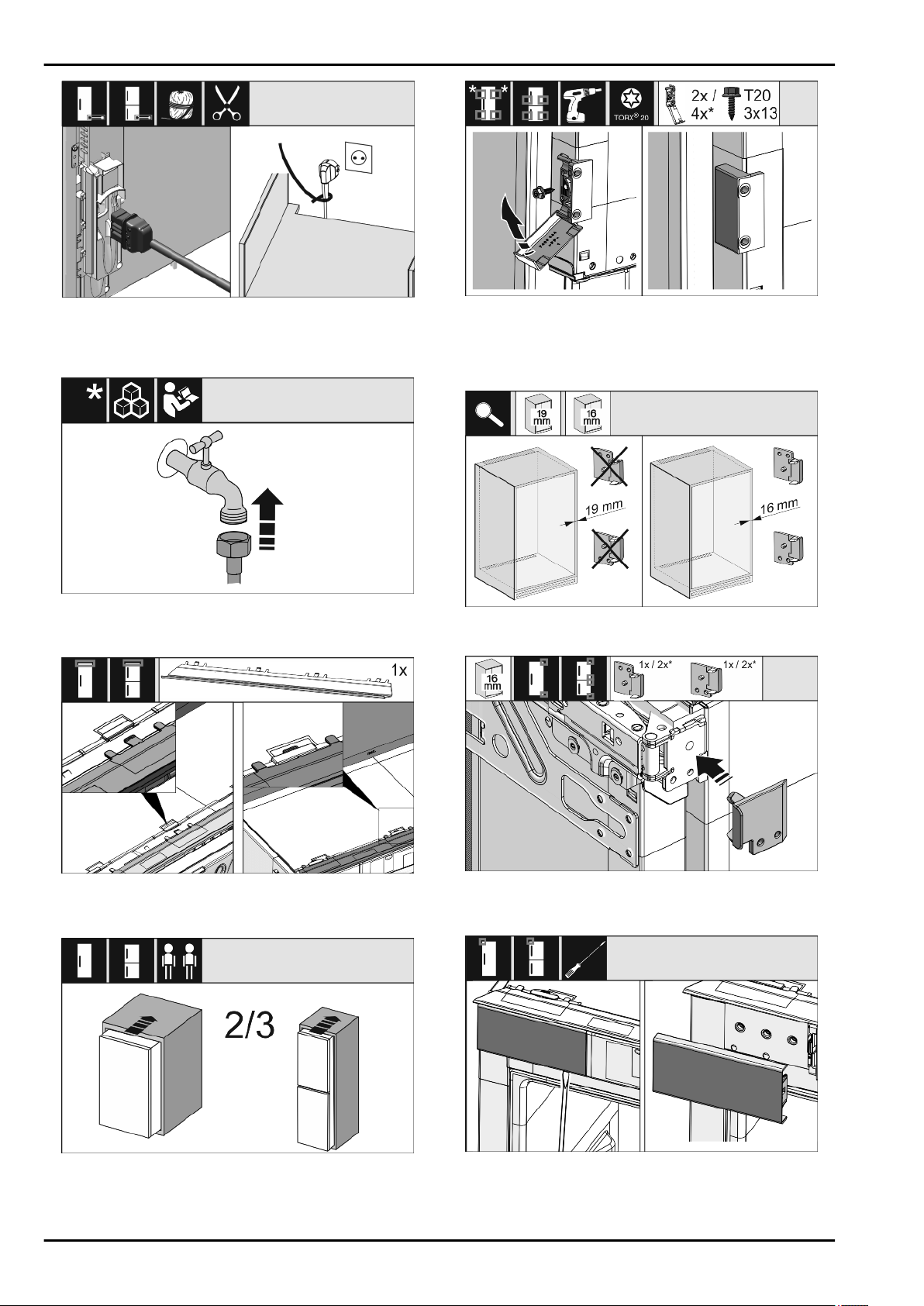
Fig. 28
*
u
Remove the power cable from the package and plug it into
the back of the appliance. Use a cable lug to lay the power
plug cord to the accessible socket.
Fig. 29
u
If necessary, install the water connection at this point,
following the instructions in the User Guide.
Fig. 30
u
Insert the adapter panel on the top of the appliance. The
panel can be moved to both sides.
Fig. 31
u
Insert the appliance 2/3 of the way into the recess.
Fig. 32
*
u
Assemble the mounting bracket. Attach the mounting
brackets to align with the cabinet door handles. If the door
is large use four mounting brackets in total. After assembly,
fold the covers onto the bracket.
Fig. 33
*
u
Check that the unit side wall is 16 mm or 19 mm thick.
Fig. 34
u
If unit walls are 16 mm thick: Clip a spacer on all hinges. No
spacer is required if unit walls are 19 mm thick.
Fig. 35
u
Use a screwdriver to loosen the cover at the top left and
remove it.
Installing the appliance in the recess
* Depending on model and options 11
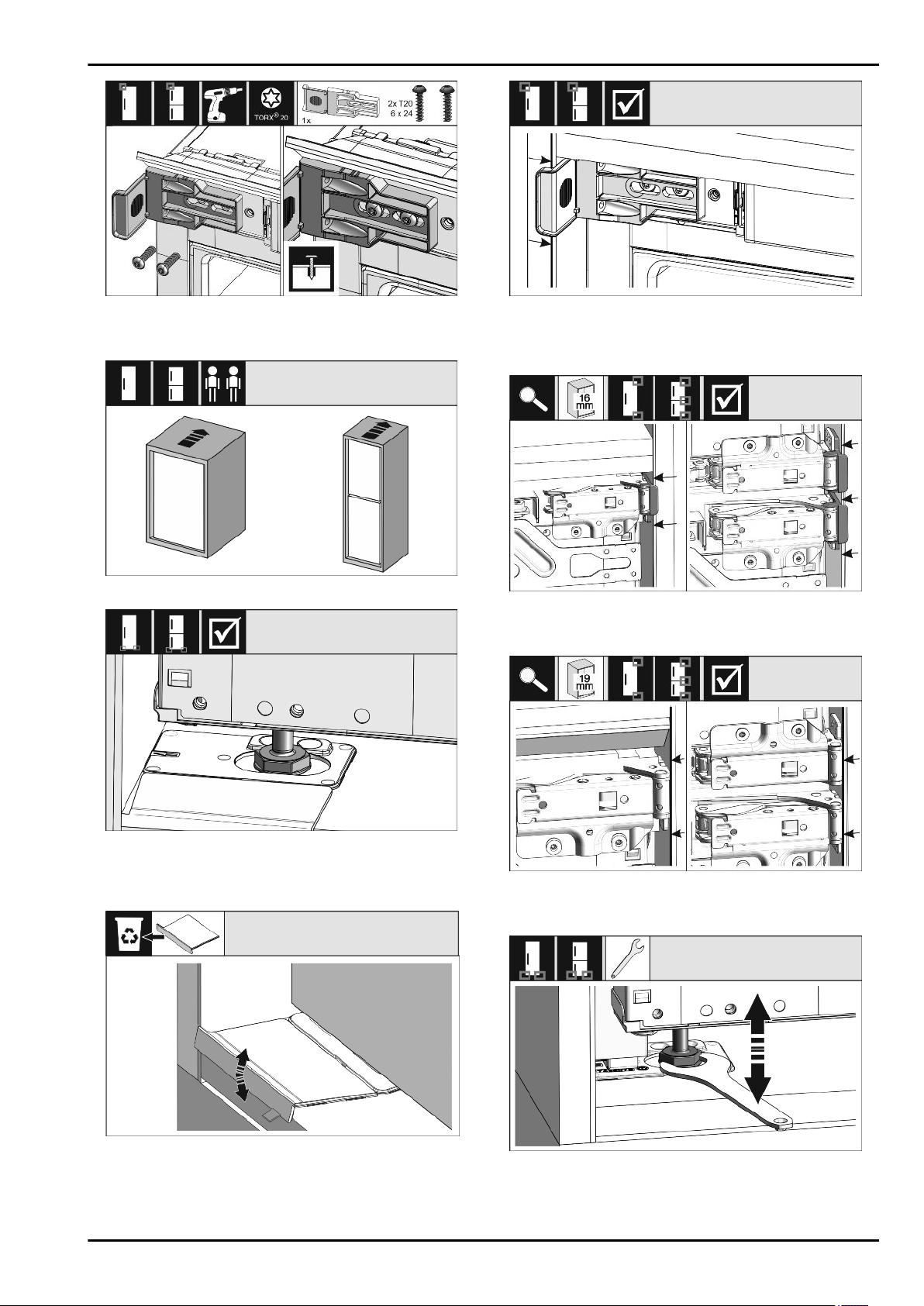
Fig. 36
u
Loosely tighten the mounting bracket screw. The bracket
should still be easy to move.
Fig. 37
Fig. 38
u
Insert the appliance all the way into the unit recess. The
adjustable feet must rest in the recesses in the brackets on
both sides.
Fig. 39
u
Remove the stopper on the mounting bracket base. Loosen
the stopper by moving it and, if necessary, pull it off with the
help of pliers.
Fig. 40
u
Check that the appliance is flush against the cabinet recess.
The mounting bracket must be attached to the side wall of
the cabinet recess.
Fig. 41
*
u
With 16 mm unit side walls, the spacers fit against the unit
recess on the hinge side.
Fig. 42
*
u
With 19 mm unit side walls, the front sides of the hinges are
positioned flush against the front of the unit side wall.
Fig. 43
u
If necessary, use the adjustable feet to correct the tilt of the
appliance.
Installing the appliance in the recess
12 * Depending on model and options
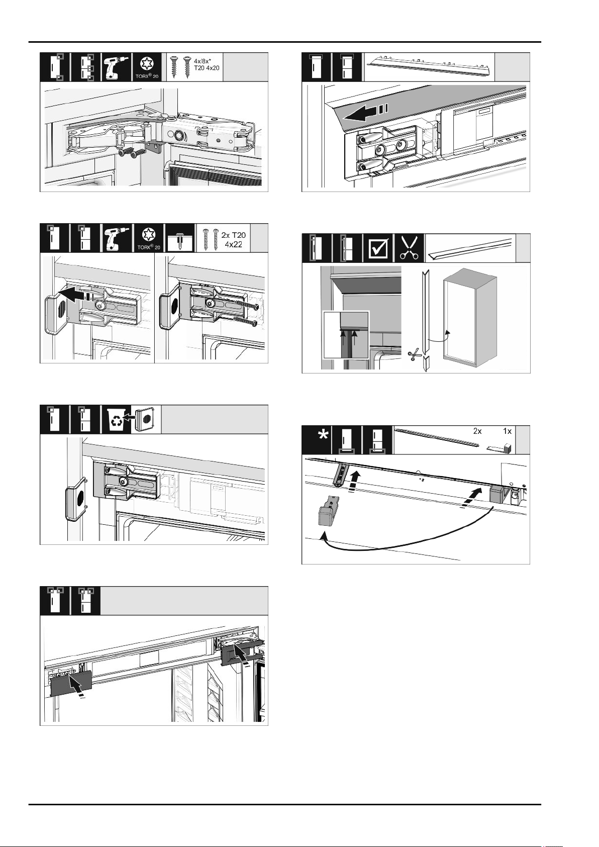
Fig. 44
u
Screw on the appliance on the hinge side.
Fig. 45
u
Move the bracket so it sits flush on the side wall of the
cabinet recess. Tighten all screws securely.
Fig. 46
u
Remove the stop from the bracket on the handle side and
dispose of it.
Fig. 47
u
Put covers into position.
Fig. 48
u
Slide the panel so that it sits flush on the side of the cabinet
wall.
Fig. 49
*
u
The trim is magnetic. Place the trim below the top cover and
press. If necessary, shorten the trim to the required length
with a sharp pair of scissors.
Fig. 50
The height adjustment is only supplied as standard for
recess heights of 140 cm and above. It is used for
sound optimisation. Both parts of the height adjustment are
included in the accessory kit.
u
To stabilise the appliance at the back underneath: Fit the
handle onto the rail of the height adjustment and push the
rail into the appliance base. Remove the handle and do the
same with the second rail.
Installing the appliance in the recess
* Depending on model and options 13
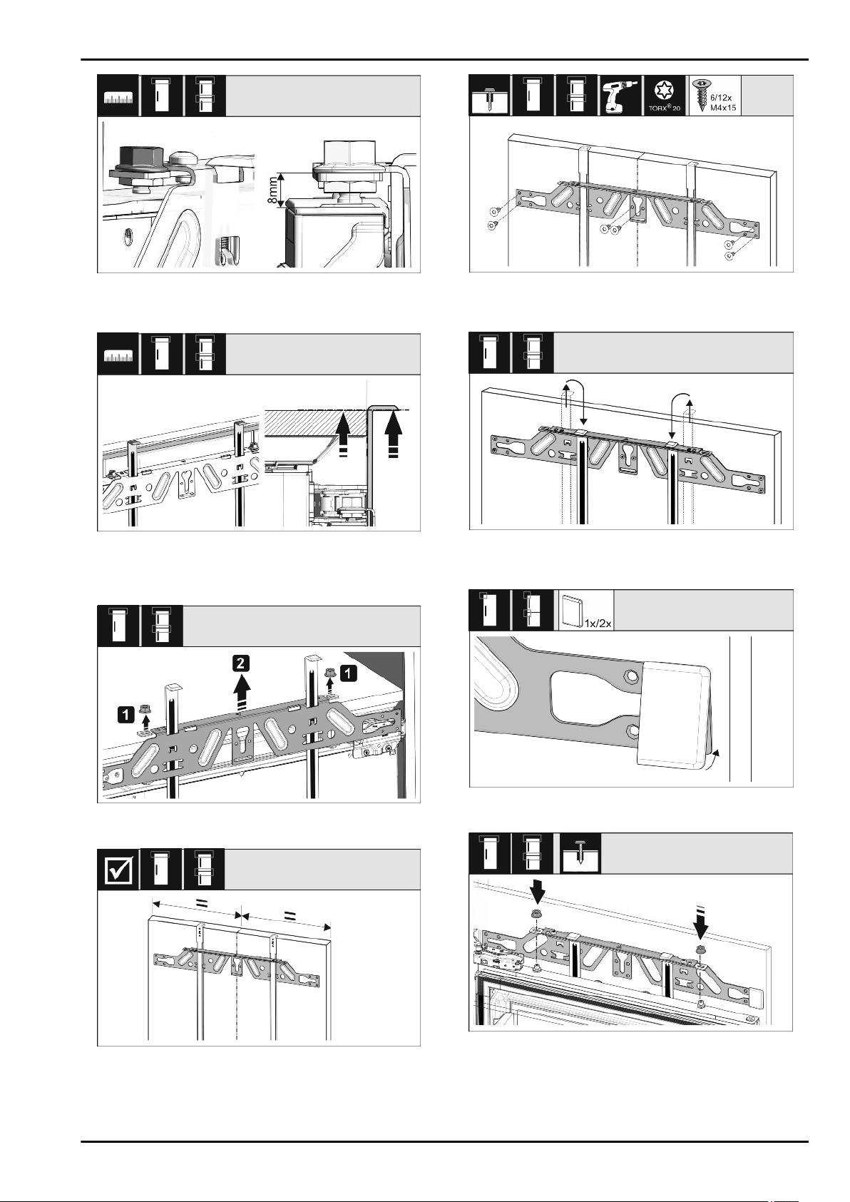
Fig. 51
*
u
Close the door and check the preset 8 mm from the upper
edge of the appliance door to the crosspiece support
Fig. 52
u
Push the assembly aids to the unit door height. Lower stop
edge of the assembly aid = upper edge of the door to be
assembled.
Fig. 53
u
Loosen the counter nut and remove the crosspiece.
Fig. 54
u
Hang the crosspiece on the inside of the unit door and make
sure it is central.
Fig. 55
u
Fix the crosspiece using at least 6 screws for chipboard
doors and at least 4 screws for panel doors.
Fig. 56
u
Remove the fitting aids, turn round and insert into the adja-
cent opening.
Fig. 57
u
Clip the cover on the crosspiece on the handle side.
Fig. 58
u
Attach the unit door and loosely screw the lock nuts onto the
adjusting bolts.
Installing the appliance in the recess
14 * Depending on model and options
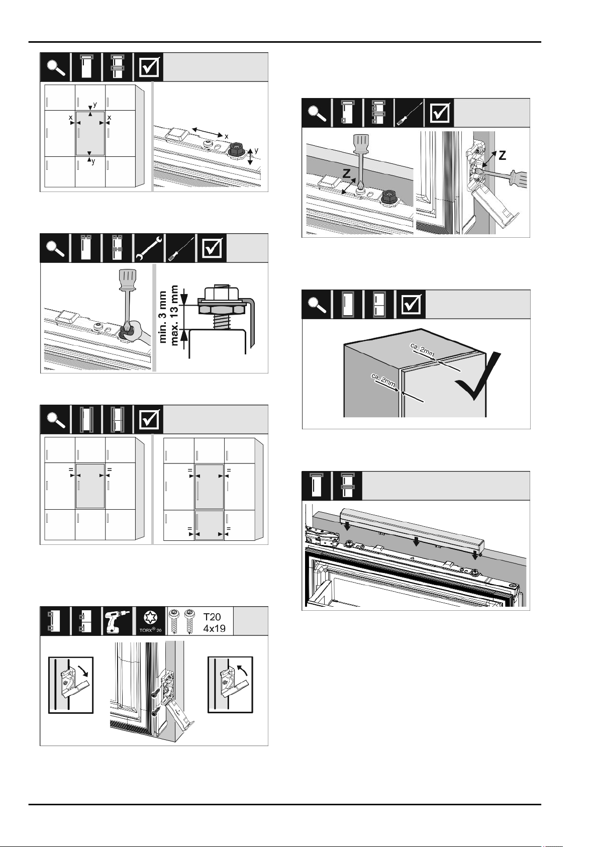
Fig. 59
u
Align the unit door in the X and Y direction using the
adjusting bolts.
Fig. 60
*
u
Screw on the counter nuts and check the height.
Fig. 61
u
Check the gap between the door and the surrounding
custom panels. For unit fronts thicker than 19 mm, take
account of the dimensions and advice in the chapter Unit
fronts.
Fig. 62
*
u
Open the cover to fit the mounting bracket on the custom
panel. Align the front edge of the mounting bracket parallel
with the custom panel edge and screw the bracket down
tightly. Fold up the cover.
Fig. 63
u
Align the custom panel in the Z direction: Loosen the
adjusting screw on the crosspiece and the screw on the
mounting bracket, then move the door.
Fig. 64
*
u
Check the distance between the unit door and the unit body.
Check all screws and retighten if necessary.
Fig. 65
u
Clip the top cover on.
Installing the appliance in the recess
* Depending on model and options 15
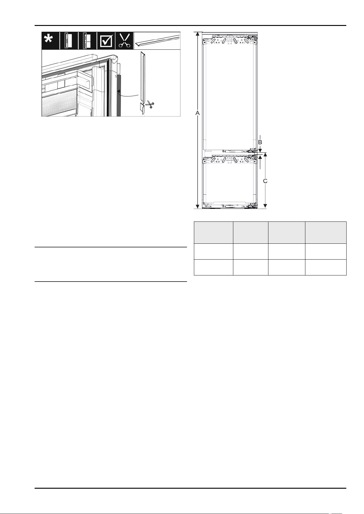
Fig. 66
u
Adjust the tread, cut it to length and place it between the
cabinet door and the appliance door.
Check the following points to make sure the appliance
is installed correctly. Otherwise, icing up, the formation of
condensate and malfunctions may occur:
w
The door must close properly.
w
The unit door must not touch the body of the unit.
w
The seal on the upper corner on the handle side must be
fitted securely.
15 Cabinet fronts
15.1 Dimensions
Depending on your model, you will need one or two cabinet
doors. The size of the cabinet door(s) depends on the overall
recess size and cabinet unit thickness.
Note
Observe the appliance and recess dimensions and follow
the installation diagrams (see 3 Appliance dimensions)
(see 4 Recess dimensions) . See the relevant catalogue for
the installation diagrams.
General requirements:
-
Please refer to our catalogues for appliance-specific recom-
mendations on size and weight for fixed door installations.
-
The cabinet unit thickness should be at least 16 mm and no
bigger than 19 mm.
-
When mounting a 2-door cabinet door, observe the recom-
mended clearances.
Fig. 67 Clearances for a 2-door
cabinet door
Recess
height*
Appliance
height (A)
(mm)*
Distance (B)
(mm)*
Clearance (C)
fixed door
(mm)*
178-2
drawers*
1770 15 549+15
178-3
drawers*
1770 15 695+15
Other cabinet door above, below or next to it:
-
Vertical gap between cabinet doors must be 4 mm.
-
Horizontal gap between cabinet doors must be 4 mm. Check
the collision factors here (see 15.3 Setting the clearance to
avoid collision) .
Weight and hinges:
-
Heavy cabinet fronts increase the stress on the hinge. The
hinge may be damaged. As such, refer to the catalogue for
the maximum weight specification for your appliance.
-
If the cabinet front exceeds the maximum permitted weight,
an appliance with door-tracking device can help by loading
the weight over several concealed hinges on the cabinet.
-
If you have long cabinet fronts that protrude a long way
above the appliance, we recommend an additional door
hinge (e.g. Kamat), which by design has the same pivot
point as the fixed door hinge used by Liebherr appliances.
Using an additional hinge (Kamat) loads the weight over
multiple points. We recommend using a milled adapter fitting
for high cabinet fronts to counteract any dragging (convex/
concave).
15.2 Mounting the cabinet front(s)
When installing, note:
- Cabinet front must be installed symmetrically to the refriger-
ator door.
- Adjoining cabinet front is exactly level.
- Adjoining cabinet front has the same edge radius as the
front of the appliance.
Cabinet fronts
16 * Depending on model and options
- Cabinet front is flat and tension-free.
- Cabinet front is adjusted to a minimum depth of approx.
2 mm to the unit body.
u
Fit the appliance into the recess (see 14 Installing the appli-
ance in the recess) .
u
Attach the cabinet front to the appliance door (see 14 Instal-
ling the appliance in the recess) .
u
Check the cabinet front does not collide with anything
(see 15.3 Setting the clearance to avoid collision) .
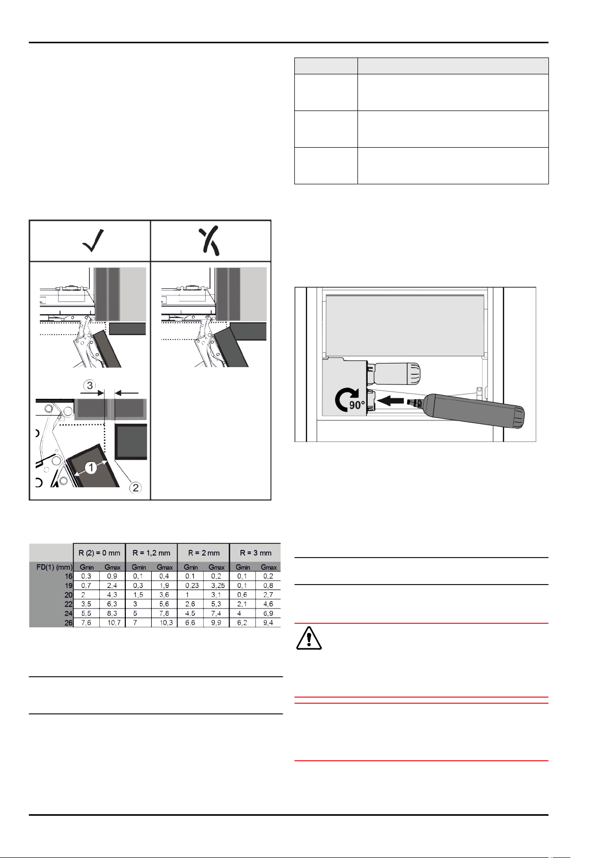
15.3 Setting the clearance to avoid
collision
After installing the cabinet front(s), check that the cabinet fronts
do not collide.
Fig. 68
(1) Front thickness (FD) (3) Clearance (S)
(2) Edge radius (R)
Fig. 69 Table of clearance limits*
G
min
= min. clearance in mm*
G
max
= max. clearance in mm*
Note
When making adjustments, always make sure that the cabinet
front suits the general appearance.
Check the collision factors and adjust them accordingly:
u
Determine the front thickness and edge radius.
u
Refer to the table for the min./max. clearance dimensions.
u
Check the clearance size against the table.
u
Do one of the following depending on the measured clear-
ance size.
Clearance Description
S > G
max
If the clearance size is greater than the two
limits, you do not need to make any adjust-
ments.
S < G
min
If the clearance size is below the limits, you
must increase it. Another option is to increase
the edge radius.
G
min
≤ S ≤
G
max
If the clearance is between the two limits, you
have to be careful. This will quickly lead to
collisions.
16 Water tank
Depending on your model, the InfinitySpring water tank is
behind the lowest drawer in the fridge or BioFresh compart-
ment
16.1 Inserting the water tank
Fig. 70
u
Remove the drawer compartment.
u
Insert the water tank and rotate approx. 90° clockwise until it
clicks in.
u
Check that the tank is sealed and no water leaks out.
u
Insert the drawer compartment.
u
Vent the water system (see the Installation Instructions,
Water Connection)
Instead of the water filter you can insert an additional water
tank.
Note
You can purchase this water tank as an optional extra.
17 Connecting the appliance
WARNING
Failure to connect properly
Fire hazard.
u
Do not use an extension cable.
u
Do not use distributor blocks.
NOTICE
Failure to connect properly
Damage to the electronics.
u
Do not use a standalone inverter.
u
Do not use an energy saving plug.
Water tank
* Depending on model and options 17

Note
Only use the power connection lead supplied.
u
A longer power connection lead can be ordered from
Customer Service.
Ensure that the following conditions are met:
- The type of current and voltage at the installation site
complies with the information on the type plate .
- The socket is earthed according to the regulations and
fused.
- The fuse tripping current is between 10 and 16 A.
- The socket is easily accessible.
- The socket is outside the back of the appliance area in the
specified area
(a, b, c)
.
u
Check the electrical connection.
u
Insert the appliance plug
(G)
into the back of the appliance.
Ensure that it clicks into place.
u
Connect the power plug to the power supply.
w
The Liebherr logo appears on the screen.
w
The display switches to the standby symbol.
Connecting the appliance
18 * Depending on model and options

Connecting the appliance
* Depending on model and options 19

home.liebherr.com/fridge-manuals
built-in fridges and freezers, fixed door
Issue date: 20211018
Part number index: 7088287-00
Liebherr-Hausgeräte Ochsenhausen GmbH
Memminger Straße 77-79
88416 Ochsenhausen
Deutschland