Loading ...

INSTALLATION AND OPERATING INSTRUCTIONS
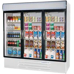
Models: MT/RI/FC
1. Installation
a. Receiving Inspection
:
Upon receipt, check all packages and accessories or optional components including legs, casters,
and shelves.
b. Legs & Casters
: (optional) (See Fig. 1)
Legs screw directly into the base. Caster are plate-mounted. To install casters, tip or raise the
cabinet one side at a time and remove the four hex head screws in each corner of the bottom.
Use these same screws to attach the mounting plate. Screw-on type legs simply screw into the
adapter nut provided in each corner of the bottom.
c. Leveling
: (See Fig. 2)
To provide adequate condensate drainage and proper door alignment and operation. It is
necessary that the cabinet be level. Level cabinet from front to rear and from side to side with
leveling bolts, or leg inserts. This should be done after cabinet has been set in its final operating
position. The leveling bolts are the same bolts used to attach the wood base to the cabinet. BE
SURE THAT DRAIN HOSE IS ATTACHED AND DRAINING PROPERLY INTO EXTERIOR
CONDENSATE PAN LOCATED BEHIND BOTTOM GRILLE ASS’Y. THE HOSE COULD
POSSIBLE BE KNOCKED LOOSE IN TRANSIT.
d. Door Handles
: (See Fig 3.)
Door handles with mounting screws are packed inside each cooler.
To mount handle, lift door gasket behind two holes in front and insert screws through the holes.
Attach handle, with offset away from cabinet corner, and tighten screws. (NOTE: It may be
necessary to adjust position of handle end mounts on handle bar to match hole spacing in door
frame.)
e. Shelves
:
Shipped inside each cabinet are shelves packed in plastic and a bag of shelf supports. Shelf
spacing is adjustable to suit requirements. See Instruction Sheet ILA-0904 for installing.
f. Door Removal and
Adjustment:
(1) Slide Doors
- Each door has its own Closing Spring located at the top and is positioned for
Proper
Tension. However if adjustment is required remove doors as follows:
a. Locate Door Rollers under slot A
፨
show in fig. 4, and lift door off track while tilting
bottom of door out.
Adjust spring by moving hook to next hole or by shortening.
If door gaskets do not seal properly follow step 1 and 2.
Step 1: Check to see if cabinet base is level.
Step 2: Adjust the Location
of door Rollers in the Roller Brackets.
(2) Swing Doors
- Spring tension in the bottom hinges is Factory Adjusted for adequate
“Swing Back
” of doors, and does not require field adjustment. For replacement parts and
instructions see enclosed instruction sheet ILA-0859.
g. Locating Cooler
:
Provide at least three inches of space
between cabinet and any adjacent wall or fixture, at left
end and rear of cabinet.
* For FC model, factory setting of temperature control is at No. 4 position (normal) which will
maintain the flower at about 42°F.
ILA-0931
SHEET 1 OF 3
REV. B
BEVERAGE-AIR®
Loading ...
Loading ...
Loading ...