Loading ...
Loading ...
Loading ...
( Continued from page 3 )
Unlike the standard gas range
THIS COOKTOP IS NOT REMOVABLE.
Do not attempt
to remove this cooktop.
GAS SURFACE BURNER ORIFICE DATA CHART (Burner Style #1)
BTU Rating / Natural Gas 5,000 9,500 12,000 14,000 16,000
Natural Gas Orifice 1.01 1.54 1.75 1.93 1.99
LP Gas Orifice .68 .89 .95 1.01 1.15
LP Orifice Marking Color Blue None Green Red Black
BTU Rating / LP Gas 4,500 8,000 10,000 11,000 14,000
_*Note: For at elevations above 2000operation
ft.,
appliance rating
_shall be reduced at the rate of 4 percent for each 1000 ft. above sea
level.
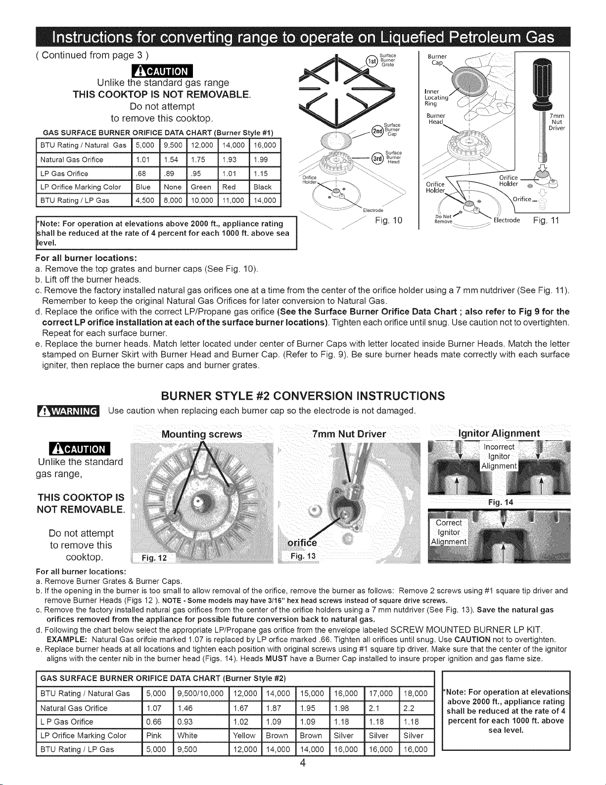
For all burner locations:
a. Remove the top grates and burner caps (See Fig. 10).
b. Lift off the burner heads.
i Fig. 10
Burner
Burner
Head
Do Not _
R..... 7 Electrode Fig. 11
7mm
Nut
Driver
c. Remove the factory installed natural gas orifices one at a time from the center of the orifice holder using a 7 mm nutdriver (See Fig. 11).
Remember to keep the original Natural Gas Orifices for later conversion to Natural Gas.
d. Replace the orifice with the correct LP/Propane gas orifice (See the Surface Burner Orifice Data Chart ; also refer to Fig 9 for the
correct LP orifice installation at each of the surface burner locations). Tighten each orifice until snug. Use caution not to overtighten.
Repeat for each surface burner.
e. Replace the burner heads. Match letter located under center of Burner Caps with letter located inside Burner Heads. Match the letter
stamped on Burner Skirt with Burner Head and Burner Cap. (Refer to Fig. 9). Be sure burner heads mate correctly with each surface
igniter, then replace the burner caps and burner grates.
Unlike the standard
gas range,
THIS COOKTOP IS
NOT REMOVABLE.
BURNER STYLE #2 CONVERSION INSTRUCTIONS
Use caution when replacing each burner cap so the electrode is not damaged.
Do not attempt
to remove this
cooktop. Fig. 12
For all burner locations:
a. Remove Burner Grates & Burner Caps.
Mounting screws
7ram Nut Driver
oril
Fig. 13
Ignitor Alignment
Fig. 14
b. If the opening in the burner is too small to allow removal of the orifice, remove the burner as follows: Remove 2 screws using #1 square tip driver and
remove Burner Heads (Figs 12 ). NOTE - Some models may have 3/16" hex head screws instead of square drive screws.
c. Remove the factory installed natural gas orifices from the center of the orifice holders using a 7 mm nutdriver (See Fig. 13). Save the natural gas
orifices removed from the appliance for possible future conversion back to natural gas.
d. Following the chart below select the appropriate LP/Propane gas orifice from the envelope labeled SCREW MOUNTED BURNER LP KIT.
EXAMPLE: Natural Gas orifcie marked 1.07 is replaced by LP orfice marked .66. Tighten all orifices until snug. Use CAUTION not to overtighten.
e. Replace burner heads at all locations and tighten each position with original screws using #1 square tip driver. Make sure that the center of the ignitor
aligns with the center nib in the burner head (Figs. 14). Heads MUST have a Burner Cap installed to insure proper ignition and gas flame size.
GAS SURFACE BURNER ORIFICE DATA CHART (Burner Style #2)
BTU Rating / Natural Gas 5,000 9,500/10,000 12,000 14,000 15,000 16,000 17,000 18,000
Natural Gas Orifice 1.07 1.46 1.67 1.87 1.95 1.98 2.1 2.2
L P Gas Orifice 0.66 0.93 1.02 1.09 1.09 1.18 1.18 1.18
LP Orifice Marking Color Pink White Yellow Brown Brown Silver Silver Silver
BTU Rating / LP Gas 5,000 9,500 12,000 14,000 14,000 16,000 16,000 16,000
4
*Note: For operation at elevations
above 2000 ft., appliance rating
shall be reduced at the rate of 4
percent for each 1000 ft. above
sea level.
Loading ...
Loading ...
Loading ...