
Loading ...
Loading ...
Loading ...
Manufacturer of Quality Air Conditioning and Heating Products • www.islandaire.com • sales@islandaire.com • (800)-886-2759
18
Wall Sleeve Installation Instructions
Preparing the Wall
Opening
•Once a satisfactory location is found and height of
unit is determined, create a wall opening to install
the wall sleeve. e rough opening should mea-
sure a minimum of 16 ½” high x 42 ½” wide.
•If opening will start right at the nished oor level,
leave enough clearance for carpeting, etc. If using
a power cord, leave enough space for the cord to
exit from under the front panel.
•When a subbase is used, the opening must start
above the nished oor to match the height of the
subbase selected.
•When construction is complete, check the wall
opening to be sure the wall sleeve will slide into the
opening without obstruction.
•If installed in a concrete or masonry wall, a lintel
must be provided in the wall opening for support.
•Do not use the wall sleeve as a lintel.
•When installed in the opening, the wall sleeve
must be horizontally level from side-to-side and
pitched (one quarter bubble in the sight glass) to
the outside.
DO NOT SLOPE THE WALL SLEEVE
TOWARD THE ROOM.
•e installer must provide adequate sealing and
insulation around the sleeve aer it is installed.
•If used, a 208/230 volt wall receptacle must be
located within 58 inches of the lower right sleeve
corner. Extension cords must not be used with the
unit.
•For installations in walls deeper than 13-7/8
inches, special care is necessary to prevent prob-
lems with rain water, condensate drainage and
intake/discharge air. Consult with your Sales Rep-
resentative before attempting such installations.
Framing
Proper building practices must be used when construct-
ing a wall opening to support a PTAC wall sleeve and
chassis. Units must be installed in accordance with all
applicable codes.
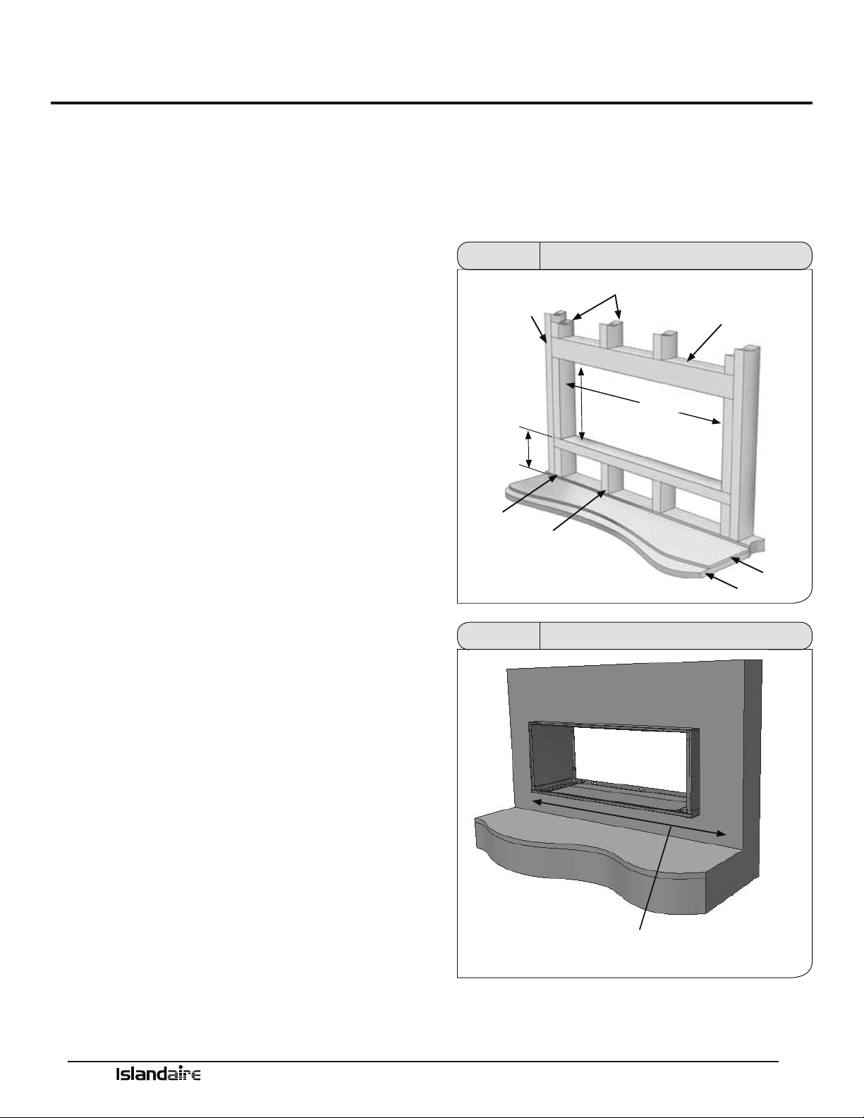
MAIN
STUD
3” FROM
FINISHED
FLOOR
CRIPPLE
JACK STUDS
16 1/2”
MIN.
HEADER - (1) 4”X 4” OR
(2) 2” X 4” ON EDGE
42 1/2”
FLOOR
JACK STUD
SUB-FLOOR
Figure 6 Framing and Minimum Wall Opening
WALL RECEPTACLE MUST BE LOCATED WITHIN 58” OF LOWER
RIGHT CORNER (208/230 VOLT UNITS ONLY)
ACCESS TO MAINS MUST BE AVAILABLE FOR ALL OTHER UNITS
Figure 7 Framing and Minimum Wall Opening
Loading ...
Loading ...
Loading ...