Loading ...
Loading ...
Loading ...
ULTIMATE RESTAURANT RANGES
OWNER’S MANUAL 1190820 REV 4 (10/14)
PAGE
10
OF 34
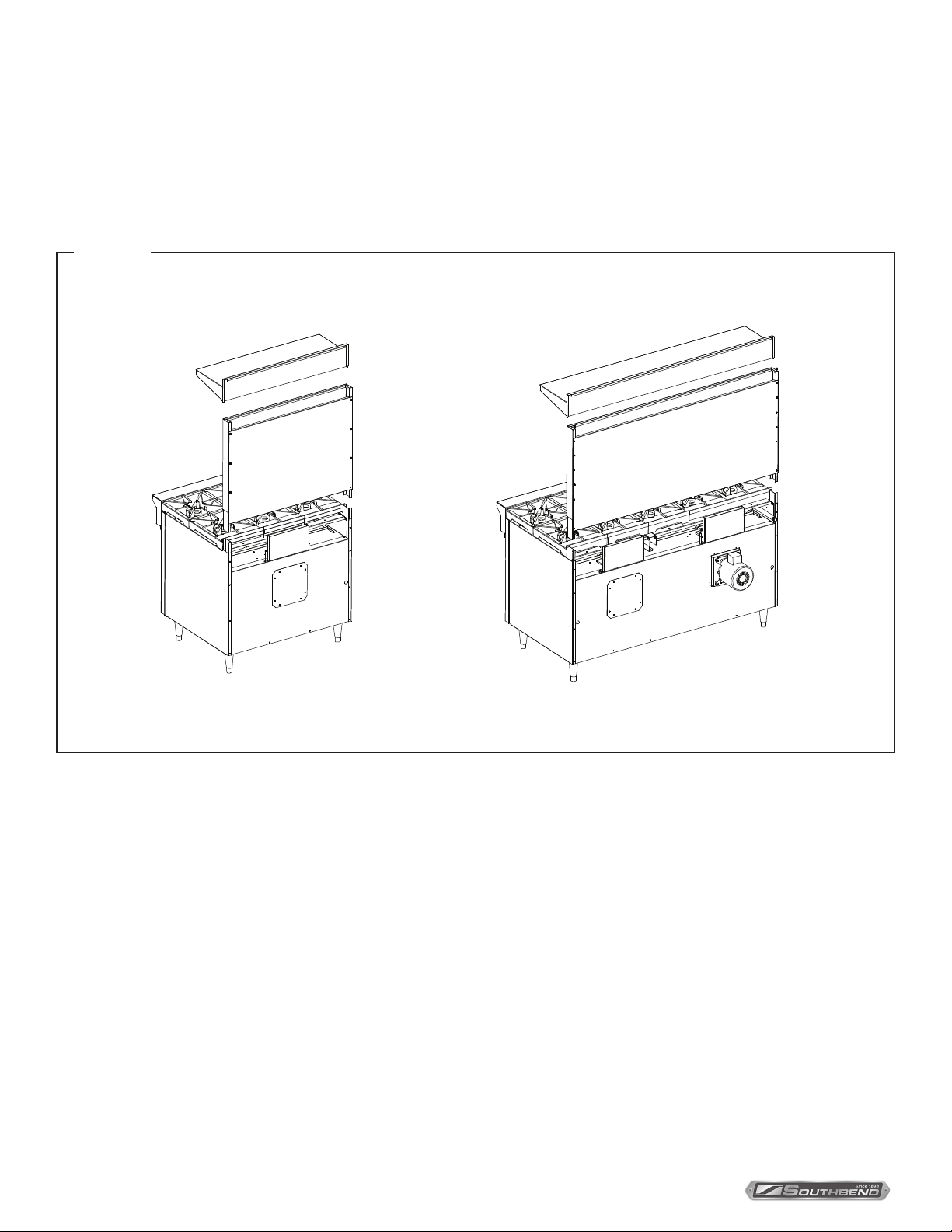
STEP 3: ATTACH FLUE RISER AND SHELF ASSEMBLY
Place the ue riser assembly on the range as shown on the appropriate diagram below.
1. Slide the ue riser assembly over the bayonets until it bottoms out, as shown below.
2. Secure ends of ue riser assembly with two (2) 1/4-20 x 3/4 hex head bolts, at washers and lockwashers.
3. Attach the shelf assembly (if ordered) to the ue riser assembly with 1/4-20 x 3/4 hex head bolts, at washers and
lockwashers.
Figure 5
INSTALLATION
Installation of Flue Riser and Shelf Assembly
Single-Oven Models Dual-Oven Models
STEP 4: ELECTRICAL CONNECTION
Wiring diagrams are located on the rear of the range. Be sure that the input voltage and phase match the requirements
shown on the serial plate (see Figure 1).
Ranges are factory-equipped either with a power cord or with one or two two-pole terminal blocks (one for each oven),
located behind cover plate(s) located on the rear of the range. To connect the supply wires, remove the appropriate cover
plate. Route the supply wires and the grounding wire through the strain relief tting to the terminal block. Insert the supply
wires, one each, into the two poles of the terminal block and tighten the screws. Insert the ground wire into the grounding
lug and tighten the screw. Re-attach the cover plate.
Three phase ranges are wired as above, using only two supply wires. The third wire is not used and must be properly
terminated.
All ranges are shipped wired as specied by factory order. Conversion between single-phase and three-phase can
be accomplished by referring to phase loading and line amperes chart on wiring diagram for wire size and ampere
requirements.
STEP 5: GAS CONNECTION
If this equipment is being installed at over 610 meters altitude and that information was not specied when ordered,
contact the appropriate authorized Southbend Service Representative or the Southbend Service Department. Failure to
install with proper orice sizing will result in poor performance and may void the warranty.
Loading ...
Loading ...
Loading ...