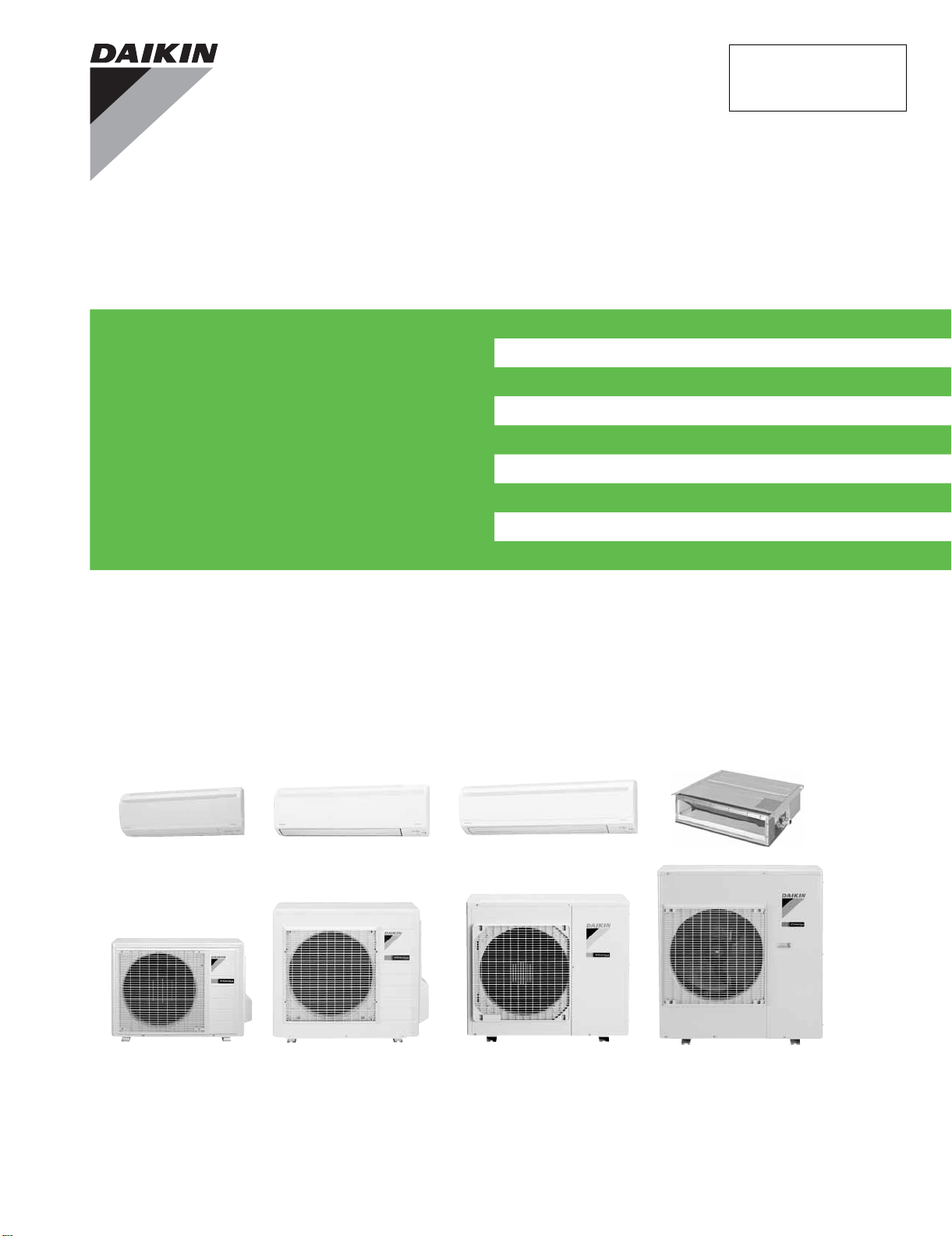
Service
Manual
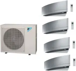
Inverter Pair
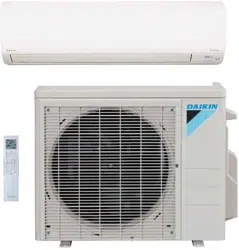
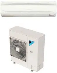
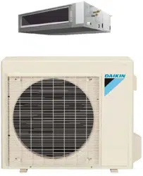
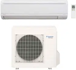
FTXS-L Series
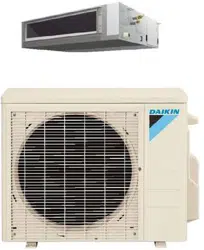
FDXS-L Series
SiUS091133
[Applied Models]
Inverter Pair : Cooling Only
Inverter Pair : Heat Pump

SiUS091133
Table of Contents i
Inverter Pair
FTXS-L Series
FDXS-L Series
Cooling Only
Indoor Unit
FTXS30LVJU
FTXS36LVJU
Outdoor Unit
RKS30LVJU
RKS36LVJU
Heat Pump
Indoor Unit
FTXS09LVJU FDXS09LVJU
FTXS12LVJU FDXS12LVJU
FTXS15LVJU
FTXS18LVJU
FTXS24LVJU
FTXS30LVJU
FTXS36LVJU
Outdoor Unit
RXS09LVJU
RXS12LVJU
RXS15LVJU
RXS18LVJU
RXS24LVJU
RXS30LVJU
RXS36LVJU

SiUS091133
ii Table of Contents
1. Safety Considerations..................................................................................i
1.1 Safety Considerations for Repair .................................................................. i
1.2 Safety Considerations for Users....................................................................ii
Part 1
List of Functions ...................................................................1
1. Functions.....................................................................................................2
1.1 FTXS Series.................................................................................................2
1.2 FDXS Series.................................................................................................4
Part 2
Specifications .......................................................................5
1. Specifications..............................................................................................6
1.1 FTXS Series.................................................................................................6
1.2 FDXS Series...............................................................................................11
Part 3
Printed Circuit Board
Connector Wiring Diagram..................................................12
1. Indoor Unit.................................................................................................13
1.1 FTXS09/12LVJU ........................................................................................13
1.2 FTXS15/18/24/30/36LVJU .........................................................................16
1.3 FDXS09/12LVJU........................................................................................ 19
2. Outdoor Unit..............................................................................................21
2.1 RXS09/12LVJU..........................................................................................21
2.2 RXS15/18LVJU..........................................................................................23
2.3 RXS24LVJU, RK(X)S30/36LVJU............................................................... 25
Part 4
Function and Control...........................................................27
1. Main Functions..........................................................................................28
1.1 Temperature Control..................................................................................28
1.2 Frequency Principle....................................................................................28
1.3 Airflow Direction Control (FTXS Series).....................................................30
1.4 Fan Speed Control for Indoor Unit .............................................................32
1.5 Program Dry Operation..............................................................................33
1.6 Automatic Operation...................................................................................34
1.7 Thermostat Control.....................................................................................35
1.8 NIGHT SET Mode......................................................................................36
1.9 ECONO Operation .....................................................................................37
1.10 INTELLIGENT EYE Operation (FTXS Series) ........................................... 38
1.11 Inverter POWERFUL Operation.................................................................39

SiUS091133
Table of Contents iii
1.12 Other Functions..........................................................................................40
2. Function of Thermistor..............................................................................41
3. Control Specification.................................................................................42
3.1 Mode Hierarchy..........................................................................................42
3.2 Frequency Control......................................................................................43
3.3 Controls at Mode Changing / Start-up........................................................45
3.4 Discharge Pipe Temperature Control.........................................................46
3.5 Input Current Control..................................................................................47
3.6 Freeze-up Protection Control.....................................................................48
3.7 Heating Peak-cut Control...........................................................................48
3.8 Outdoor Fan Control...................................................................................49
3.9 Liquid Compression Protection Function....................................................49
3.10 Defrost Control...........................................................................................50
3.11 Electronic Expansion Valve Control...........................................................51
3.12 Malfunctions...............................................................................................54
Part 5
Operation Manual................................................................55
1. System Configuration................................................................................56
2. FTXS Series..............................................................................................57
2.1 Remote Controller......................................................................................57
2.2 AUTO · DRY · COOL · HEAT · FAN Operation..........................................59
2.3 Adjusting the Airflow Direction and Rate....................................................61
2.4 COMFORT AIRFLOW / INTELLIGENT EYE Operation............................. 64
2.5 POWERFUL Operation..............................................................................66
2.6 OUTDOOR UNIT QUIET Operation...........................................................67
2.7 ECONO Operation .....................................................................................68
2.8 OFF TIMER Operation...............................................................................69
2.9 ON TIMER Operation.................................................................................70
2.10 WEEKLY TIMER Operation ....................................................................... 71
3. FDXS Series .............................................................................................77
3.1 Remote Controller......................................................................................77
3.2 AUTO · DRY · COOL · HEAT · FAN Operation..........................................79
3.3 Adjusting the Airflow Rate..........................................................................81
3.4 POWERFUL Operation..............................................................................82
3.5 OUTDOOR UNIT QUIET Operation...........................................................83
3.6 ECONO Operation .....................................................................................84
3.7 OFF TIMER Operation...............................................................................85
3.8 ON TIMER Operation.................................................................................86
Part 6
Service Diagnosis................................................................87
1. Troubleshooting with LED.........................................................................89
1.1 Indoor Unit..................................................................................................89
1.2 Outdoor Unit...............................................................................................89

SiUS091133
iv Table of Contents
2. Problem Symptoms and Measures...........................................................90
3. Service Check Function............................................................................91
4. Troubleshooting ........................................................................................94
4.1 Error Codes and Description......................................................................94
4.2 Indoor Unit PCB Abnormality .....................................................................95
4.3 Freeze-up Protection Control or Heating Peak-cut Control........................ 97
4.4 Fan Motor or Related Abnormality .............................................................99
4.5 Thermistor or Related Abnormality (Indoor Unit)......................................103
4.6 Refrigerant Shortage................................................................................104
4.7 Low-voltage Detection or Over-voltage Detection....................................107
4.8 Signal Transmission Error (between Indoor Unit and Outdoor Unit)........109
4.9 Signal Transmission Error on Outdoor Unit PCB
(24/30/36 Class Only)111
4.10 Unspecified Voltage (between Indoor Unit and Outdoor Unit) .................112
4.11 Outdoor Unit PCB Abnormality.................................................................113
4.12 OL Activation (Compressor Overload) .....................................................115
4.13 Compressor Lock.....................................................................................116
4.14 DC Fan Lock ............................................................................................117
4.15 Input Overcurrent Detection.....................................................................118
4.16 Four-Way Valve Abnormality....................................................................119
4.17 Discharge Pipe Temperature Control.......................................................121
4.18 High Pressure Control in Cooling.............................................................123
4.19 Compressor System Sensor Abnormality ................................................125
4.20 Position Sensor Abnormality....................................................................128
4.21 DC Voltage / Current Sensor Abnormality (09/12 Class Only).................131
4.22 CT or Related Abnormality (24/30/36 Class Only)...................................132
4.23 Thermistor or Related Abnormality (Outdoor Unit)...................................134
4.24 Electrical Box Temperature Rise.............................................................. 136
4.25 Radiation Fin Temperature Rise ..............................................................138
4.26 Output Overcurrent Detection ..................................................................140
5. Check......................................................................................................142
5.1 Thermistor Resistance Check..................................................................142
5.2 Fan Motor Connector Output Check ........................................................143
5.3 Hall IC Check ...........................................................................................143
5.4 Power Supply Waveforms Check.............................................................144
5.5 Electronic Expansion Valve Check...........................................................144
5.6 Four-Way Valve Performance Check.......................................................145
5.7 Inverter Units Refrigerant System Check.................................................145
5.8 “Inverter Checker” Check.........................................................................146
5.9 Rotation Pulse Check on the Outdoor Unit PCB......................................148
5.10 Installation Condition Check.....................................................................149
5.11 Discharge Pressure Check.......................................................................150
5.12 Outdoor Fan System Check.....................................................................150
5.13 Main Circuit Short Check..........................................................................151
5.14 Capacitor Voltage Check..........................................................................152
5.15 Power Module Check...............................................................................153

SiUS091133
Table of Contents v
Part 7
Removal Procedure...........................................................155
1. Indoor Unit: FTXS09/12LVJU..................................................................157
1.1 Removal of Air Filters...............................................................................157
1.2 Removal of Front Panel............................................................................159
1.3 Removal of Front Grille ............................................................................160
1.4 Removal of Horizontal Blades / Vertical Blades.......................................162
1.5 Removal of Electrical Box ........................................................................166
1.6 Removal of PCBs.....................................................................................170
1.7 Removal of Swing Motors ........................................................................ 176
1.8 Removal of Indoor Heat Exchanger.........................................................180
1.9 Removal of Fan Motor..............................................................................183
2. Indoor Unit: FTXS15/18/24LVJU.............................................................186
2.1 Removal of Air Filters / Front Panel .........................................................186
2.2 Removal of Front Grille ............................................................................189
2.3 Removal of Electrical Box ........................................................................192
2.4 Removal of PCBs.....................................................................................196
2.5 Removal of Horizontal Blades / Swing Motors.........................................205
2.6 Removal of Indoor Heat Exchanger.........................................................213
2.7 Removal of Fan Motor / Fan Rotor...........................................................217
2.8 Removal of Vertical Blade ASSYs............................................................220
3. Indoor Unit: FTXS30/36LVJU..................................................................221
3.1 Removal of Air Filters / Front Panel .........................................................221
3.2 Removal of Front Grille ............................................................................224
3.3 Removal of Electrical Box ........................................................................228
3.4 Removal of PCBs.....................................................................................232
3.5 Removal of Horizontal Blades / Swing Motors.........................................241
3.6 Removal of Fan Motor..............................................................................250
3.7 Removal of Indoor Heat Exchanger.........................................................254
3.8 Removal of Fan Rotor..............................................................................258
3.9 Removal of Vertical Blade ASSYs............................................................260
4. Outdoor Unit: RXS09/12LVJU.................................................................261
4.1 Removal of Outer Panels / Fan Motor......................................................261
4.2 Removal of Electrical Box ........................................................................270
4.3 Removal of PCBs.....................................................................................273
4.4 Removal of Reactor / Partition Plate........................................................281
4.5 Removal of Sound Blankets.....................................................................283
4.6 Removal of Four-Way Valve ....................................................................285
4.7 Removal of Compressor...........................................................................288
5. Outdoor Unit: RXS15/18LVJU.................................................................290
5.1 Removal of Outer Panels.........................................................................290
5.2 Removal of Outdoor Fan / Fan Motor.......................................................293
5.3 Removal of Electrical Box ........................................................................297
5.4 Removal of PCBs.....................................................................................308
5.5 Removal of Sound Blankets / Thermistors...............................................316
5.6 Removal of Four-Way Valve ....................................................................320

SiUS091133
vi Table of Contents
5.7 Removal of Electronic Expansion Valve...................................................321
5.8 Removal of Compressor...........................................................................323
6. Outdoor Unit: RXS24LVJU......................................................................326
6.1 Removal of Outer Panels.........................................................................326
6.2 Removal of Electrical Box ........................................................................340
6.3 Removal of PCBs.....................................................................................344
6.4 Removal of Fan Motor..............................................................................347
6.5 Removal of Coils / Thermistors................................................................ 348
6.6 Removal of Sound Blankets.....................................................................351
6.7 Removal of Compressor...........................................................................354
7. Outdoor Unit: RKS30/36LVJU, RXS30/36LVJU .....................................356
7.1 Removal of Outer Panels.........................................................................356
7.2 Removal of Electrical Box ........................................................................367
7.3 Removal of PCBs.....................................................................................371
7.4 Removal of Fan Motor..............................................................................374
7.5 Removal of Coils / Thermistors................................................................ 375
7.6 Removal of Sound Blankets.....................................................................378
7.7 Removal of Compressor...........................................................................380
Part 8
Trial Operation and
Field Settings ....................................................................382
1. Pump Down Operation............................................................................383
2. Forced Cooling Operation.......................................................................384
3. Trial Operation ........................................................................................386
4. Field Settings ..........................................................................................387
4.1 Model Type Setting ..................................................................................387
4.2 Temperature Display Switch ....................................................................387
4.3 When 2 Units are Installed in 1 Room......................................................388
4.4 Facility Setting Jumper and Switch (Cooling at Low Outdoor
Temperature)............................................................................................389
4.5 Jumper Settings .......................................................................................390
5. Application of Silicon Grease to a Power Transistor and a Diode Bridge391
Part 9
Appendix............................................................................392
1. Piping Diagrams......................................................................................393
1.1 Indoor unit ................................................................................................ 393
1.2 Outdoor Unit.............................................................................................396
2. Wiring Diagrams......................................................................................399
2.1 Indoor Unit................................................................................................399
2.2 Outdoor Unit.............................................................................................401

SiUS091133
Table of Contents vii

Safety Considerations SiUS091133
viii
1. Safety Considerations
Read these SAFETY CONSIDERATIONS carefully before performing any repair work. Comply with these safety symbols without
fail.Meanings of DANGER, WARNING, CAUTION, and NOTE Symbols:
DANGER .............. Indicates an imminently hazardous situation which, if not avoided, will result in death or serious injury.
WARNING ............ Indicates a potentially hazardous situation which, if not avoided, could result in death or serious injury.
CAUTION ............. Indicates a potentially hazardous situation which, if not avoided, may result in minor or moderate injury. It
may also be used to alert against unsafe practices.
NOTE .................. Indicates situations that may result in equipment or property-damage accidents only.
1.1 Safety Considerations for Repair
• If refrigerant gas leaks during repair or service, ventilate the area immediately. Refrigerant gas may produce toxic gas if
it comes into contact with flames. Refrigerant gas is heavier than air and replaces oxygen. In the event of an accident, a
massive leak could lead to oxygen depletion, especially in basements, and an asphyxiation hazard could occur leading
to serious injury or death.
• Do not start or stop the air conditioner operation by plugging or unplugging the power cable plug if a plug is used.
Plugging or unplugging the power cable plug to operate the equipment may cause an electrical shock or fire.
• Use parts listed in the service parts list and appropriate tools to conduct repair work. The use of inappropriate parts
or tools may cause an electrical shock or fire.
• Disconnect power before disassembling the equipment for repairs. Working on the equipment that is connected to
the power supply may cause an electric shock. If it is necessary to supply power to the equipment to conduct repairs
or to inspect the circuits, do not touch any electrically charged sections of the equipment.
• The step-up capacitor supplies high-voltage electricity to the electrical components of the outdoor unit. Discharge
the capacitor completely before conducting repair work. A charged capacitor may cause an electrical shock.
• If refrigerant gas is discharged during repair work, do not touch the discharged refrigerant gas. The refrigerant gas
may cause frostbite.
• Use only pipes, flare nuts, tools, and other materials designed specifically for R410A refrigerant systems. Never use
tools or materials designed for R22 refrigerant systems on an R410A refrigerant system. Doing so can cause a
serious accident or an equipment failure.
• Check to see if the parts and wires are mounted and connected properly, and if the connections at the soldered or
crimped terminals are secure. Improper installation and connections may cause excessive heat generation, fire, or
electrical shock.
• Prior to disconnecting the suction or discharge pipe from the compressor at the welded section, pump-down the
refrigerant gas completely in a well-ventilated place first. If there is refrigerant gas or oil remaining inside the
compressor, the refrigerant gas or oil can discharge when the pipe is being disconnected and it may cause an injury.
• Wear a safety helmet, gloves, and a safety belt when working at an elevated height of more than 6.5 ft (2 m). Insufficient
safety measures may cause a fall resulting in injury.
• Do not mix air or gas other than the specified refrigerant R410A to the refrigerant system. If air enters the refrigerant
systems, it can cause an excessive high pressure resulting in equipment damage and injury.
• When relocating the equipment, check if the new installation site has sufficient strength to withstand the weight of the
equipment. If the installation site does not have sufficient strength and the equipment is not properly secured, the
equipment may fall and cause injury.
• Securely fasten the outside unit terminal cover (panel). If the terminal cover/panel is not fastened properly, dust or
water may enter the outside unit causing fire or electric shock.
• When relocating the system, keep the refrigerant circuit free from substances other than the specified refrigerant (R-
410A) such as air. Any presence of air or other foreign substance in the refrigerant circuit can cause an abnormal
pressure rise or rupture, resulting in injury.
• If refrigerant gas leaks, locate the leaking point and repair it before charging refrigerant. After charging refrigerant,
check for refrigerant leaks. If the leaking point cannot be located and the repair work must be stopped, perform a
pump-down and close the service valve to prevent the refrigerant gas from leaking into the room. The refrigerant gas
itself is harmless, but it may generate toxic gases if it comes into contact with flames.

SiUS091133 Safety Considerations
ix
• Do not repair the electrical components with wet hands. Working on the equipment with wet hands may cause an
electrical shock.
• Do not clean the air conditioner by splashing water on it. Washing the unit with water may cause an electrical shock.
• Ground the unit when repairing equipment in a humid or wet place to avoid electrical shocks.
• Turn off the power when cleaning the equipment to prevent internal fans that rotate at high speed from starting
suddenly as they can cause injury.
• Let the refrigerant lines cool down before performing any repair work. Working on the unit when the refrigerant lines
are hot may cause burns.
• All welding and cutting operations must be done in a well-ventilated place to prevent the accumulation of toxic fumes
or possibly oxygen deficiency to occur.
• Check the grounding and repair it if the equipment is not properly grounded. Improper grounding may cause an
electrical shock.
• Measure the insulation resistance after the repair. The resistance must be 1M or higher. Faulty insulation may
cause an electrical shock.
• Check the drainage of the indoor unit after finishing repair work. Faulty drainage may cause water to enter the room
resulting in wet floors and furniture.
• Do not tilt the unit when removing it. The water inside the unit may spill resulting in wet floors and furniture.
• Dismantling of the unit, disposal of the refrigerant, oil, and additional parts, should be done in accordance with the
relevant local, state, and national regulations.
1.2 Safety Considerations for Users
• Never attempt to modify the equipment. Doing so can cause electrical shock, excessive heat generation, or fire.
• If the power cable and lead wires have scratches or have become deteriorated, have them replaced. Damaged cable
and wires may cause an electrical shock or fire.
• Do not use a joined power cable or an extension cord, or share the same power outlet with other electrical appliances
as it may cause an electrical shock or fire.
• Use an exclusive power circuit for the equipment. Insufficient circuit amperage capacity may cause an electrical
shock or fire.
• Do not damage or modify the power cable. Damaged or modified power cables may cause an electrical shock or fire.
Placing heavy items on the power cable or pulling the power cable may damage the cable.
• Check the unit foundation for damage on a continual basis, especially if it has been in use for a long time. If left in a
damaged condition, the unit may fall and cause injury. If the installation platform or frame has corroded, have it
replaced. A corroded platform or frame may cause the unit to fall resulting in injury.
• If the unit has a power cable plug and it is dirty, clean the plug before securely inserting it into a power outlet. If the
plug has a loose connection, tighten it or it may cause electrical shock or fire.
• After replacing the battery in the remote controller, dispose of the old battery to prevent children from swallowing it.
If a child swallows the battery, see a doctor immediately.
• Never remove the fan guard of the unit. A fan rotating at high speed without the fan guard is very dangerous.
• Before cleaning the unit, stop the operation of the unit by turning the power off or by pulling the power cable plug out
from its receptacle. Otherwise an electrical shock or injury may result.
• Do not wipe the controller operation panel with benzene, thinner, chemical dust cloth, etc. The panel may get
discolored or the coating can peel off. If it is extremely dirty, soak a cloth in a water-diluted neutral detergent, squeeze
it well, and wipe the panel clean. Then wipe it with another dry cloth.

SiUS091133
1 List of Functions
Part 1
List of Functions
1. Functions.....................................................................................................2
1.1 FTXS Series.................................................................................................2
1.2 FDXS Series.................................................................................................4
SiUS091133 Functions
List of Functions 2
1. Functions
1.1 FTXS Series
Category Functions
FTXS09/12/15/18LVJU
RXS09/12/15/18LVJU
FTXS24LVJU
RXS24LVJU
Category Functions
FTXS09/12/15/18LVJU
RXS09/12/15/18LVJU
FTXS24LVJU
RXS24LVJU
Basic
Function
Inverter (with Inverter Power Control) Health &
Clean
Air-Purifying Filter — —
Operation Limit for Cooling (°FDB)
14 ~
114.8
14 ~
114.8
Photocatalytic Deodorizing Filter — —
Operation Limit for Heating (°FWB)
5 ~
64.4
5 ~
64.4
Air-Purifying Filter with Photocatalytic
Deodorizing Function
——
PAM Control
Titanium Apatite Photocatalytic
Air-Purifying Filter
Compressor Oval Scroll Compressor — —
Swing Compressor Air Filter (Prefilter)
Rotary Compressor — — Wipe-clean Flat Panel
Reluctance DC Motor Washable Grille — —
Comfortable
Airflow
Power-Airflow Louver (Horizontal
Blade)
——
MOLD PROOF Operation — —
Heating Dry Operation — —
Power-Airflow Dual Louvers Good-Sleep Cooling Operation — —
Power-Airflow Diffuser — — Timer WEEKLY TIMER Operation
Wide-Angle Fins (Vertical Blades) 24-Hour ON/OFF TIMER
Vertical Auto-Swing (Up and Down) NIGHT SET Mode
Horizontal Auto-Swing (Right and Left) Worry Free
“Reliability &
Durability”
Auto-Restart (after Power Failure)
3-D Airflow Self-Diagnosis (Digital, LED) Display
COMFORT AIRFLOW Operation Wiring Error Check Function — —
Comfort
Control
Auto Fan Speed
Anticorrosion Treatment of Outdoor
Heat Exchanger
Indoor Unit Quiet Operation
NIGHT QUIET Mode (Automatic) — — Flexibility Multi-Split / Split Type Compatible
Indoor Unit
—
OUTDOOR UNIT QUIET Operation
(Manual)
H/P, C/O Compatible Indoor Unit — —
INTELLIGENT EYE Operation Flexible Power Supply Correspondence — —
Quick Warming Function Chargeless 32.8 ft 32.8 ft
Hot-Start Function Either Side Drain (Right or Left)
Automatic Defrosting Power Selection — —
Operation Automatic Operation
Low Temperature Cooling Operation
Program Dry Function
°F/°C Changeover R/C Temperature
Display (factory setting: °F)
Fan Only Remote
Control
5-Room Centralized Controller (Option)
Lifestyle
Convenience
New POWERFUL Operation
(Non-Inverter)
——
Remote Control Adaptor
(Normal Open-Pulse Contact) (Option)
Inverter POWERFUL Operation
Remote Control Adaptor
(Normal Open Contact) (Option)
Priority-Room Setting — —
COOL / HEAT Mode Lock — — DIII-NET Compatible (Adaptor) (Option)
HOME LEAVE Operation — — Remote
Controller
Wireless
ECONO Operation Wired (Option)
Indoor Unit [ON/OFF] Button
Signal Receiving Sign
R/C with Back Light
Temperature Display — —
Note: : Holding Functions
— : No Functions
Functions SiUS091133
3 List of Functions
Category Functions
FTXS30/36LVJU
RKS30/36LVJU
FTXS30/36LVJU
RXS30/36LVJU
Category Functions
FTXS30/36LVJU
RKS30/36LVJU
FTXS30/36LVJU
RXS30/36LVJU
Basic
Function
Inverter (with Inverter Power Control) Health &
Clean
Air-Purifying Filter — —
Operation Limit for Cooling (°FDB)
14 ~
114.8
14 ~
114.8
Photocatalytic Deodorizing Filter — —
Operation Limit for Heating (°FWB) —
5 ~
64.4
Air-Purifying Filter with Photocatalytic
Deodorizing Function
——
PAM Control
Titanium Apatite Photocatalytic
Air-Purifying Filter
Compressor Oval Scroll Compressor — — Air Filter (Prefilter)
Swing Compressor Wipe-Clean Flat Panel
Rotary Compressor — — Washable Grille — —
Reluctance DC Motor MOLD PROOF Operation — —
Comfortable
Airflow
Power-Airflow Louver (Horizontal
Blade)
— — Heating Dry Operation — —
Power-Airflow Dual Louvers Good-Sleep Cooling Operation — —
Power-Airflow Diffuser — — Timer WEEKLY TIMER
Wide-Angle Fins (Vertical Blades) 24-Hour ON/OFF TIMER
Vertical Auto-Swing (Up and Down) NIGHT SET Mode
Horizontal Auto-Swing (Right and Left) Worry
Free
“Reliability
&
Durability”
Auto-Restart (after Power Failure)
3-D Airflow Self-Diagnosis (Digital, LED) Display
COMFORT AIRFLOW Operation Wiring Error Check Function — —
Comfort
Control
Auto Fan Speed
Anticorrosion Treatment of Outdoor Heat
Exchanger
Indoor Unit Quiet Operation Flexibility Multi-Split / Split Type Compatible Indoor Unit — —
NIGHT QUIET Mode (Automatic) — — H/P, C/O Compatible Indoor Unit
OUTDOOR UNIT QUIET Operation
(Manual)
Flexible Power Supply Correspondence — —
INTELLIGENT EYE Operation Chargeless
32.8
ft
32.8
ft
Quick Warming Function
(Preheating Operation)
— Either Side Drain (Right or Left)
Hot-Start Function — Power Selection — —
Automatic Defrosting — Low Temperature Cooling Operation
Operation
Automatic Operation —
°F/°C Changeover R/C Temperature Display
(factory setting : °F)
Program Dry Function Remote
Control
5-Rooms Centralized Controller (Option)
Fan Only
Remote Control Adaptor
(Normal Open-Pulse Contact) (Option)
Lifestyle
Convenience
New POWERFUL Operation
(Non-Inverter)
——
Remote Control Adaptor
(Normal Open Contact) (Option)
Inverter POWERFUL Operation DIII-NET Compatible (Adaptor) (Option)
Priority-Room Setting — — Remote
Controller
Wireless
COOL / HEAT Mode Lock — — Wired (Option)
HOME LEAVE Operation — —
ECONO Operation
Ultra low
ambient
cooling
function
Cooling to - 40°F/-40°C with field installed
accessory kit RK530/36LVJU only
—
Indoor Unit [ON/OFF] Button
Signal Receiving Sign
R/C with Back Light
Temperature Display — —
Note: : Holding Functions
— : No Functions
SiUS091133 Functions
List of Functions 4
1.2 FDXS Series
Category Functions
FDXS09/12LVJU
RXS09/12LVJU
Category Functions
FDXS09/12LVJU
RXS09/12LVJU
Basic
Function
Inverter (with Inverter Power Control) Health &
Clean
Air-Purifying Filter —
Operation Limit for Cooling (°FDB)
14 ~
114.8
Photocatalytic Deodorizing Filter —
Operation Limit for Heating (°FWB)
5 ~
64.4
Air-Purifying Filter with Photocatalytic
Deodorizing Function
—
PAM Control
Titanium Apatite Photocatalytic
Air-Purifying Filter
—
Compressor Oval Scroll Compressor —
Swing Compressor Air Filter (Prefilter)
Rotary Compressor — Wipe-clean Flat Panel —
Reluctance DC Motor Washable Grille —
Comfortable
Airflow
Power-Airflow Louver (Horizontal Blade) — MOLD PROOF Operation —
Power-Airflow Dual Louvers — Heating Dry Operation —
Power-Airflow Diffuser — Good-Sleep Cooling Operation —
Wide-Angle Fins (Vertical Blades) — Timer WEEKLY TIMER Operation —
Vertical Auto-Swing (Up and Down) — 24-Hour ON/OFF TIMER
Horizontal Auto-Swing (Right and Left) — NIGHT SET Mode
3-D Airflow — Worry Free
“Reliability &
Durability”
Auto-Restart (after Power Failure)
COMFORT AIRFLOW Operation — Self-Diagnosis (Digital, LED) Display
Comfort
Control
Auto Fan Speed Wiring Error Check Function —
Indoor Unit Quiet Operation
Anticorrosion Treatment of Outdoor Heat
Exchanger
NIGHT QUIET Mode (Automatic) — Flexibility Multi-Split / Split Type Compatible Indoor Unit
OUTDOOR UNIT QUIET Operation (Manual) H/P, C/O Compatible Indoor Unit —
INTELLIGENT EYE Operation — Flexible Power Supply Correspondence —
Quick Warming Function Chargeless 32.8 ft
Hot-Start Function Either Side Drain (Right or Left) —
Automatic Defrosting Power Selection —
Operation Automatic Operation Low Temperature Cooling Operation
Program Dry Function
°F/°C Changeover R/C Temperature Display
(factory setting: °F)
Fan Only Remote
Control
5-Room Centralized Controller (Option)
Lifestyle
Convenience
New POWERFUL Operation
(Non-Inverter)
—
Remote Control Adaptor
(Normal Open-Pulse Contact) (Option)
Inverter POWERFUL Operation
Remote Control Adaptor
(Normal Open Contact) (Option)
Priority-Room Setting —
COOL / HEAT Mode Lock — DIII-NET Compatible (Adaptor) (Option)
HOME LEAVE Operation — Remote
Controller
Wireless
ECONO Operation Wired (Option)
Indoor Unit [ON/OFF] Button
Signal Receiving Sign
R/C with Back Light
Temperature Display —
Note: : Holding Functions
— : No Functions

SiUS091133
5 Specifications
Part 2
Specifications
1. Specifications..............................................................................................6
1.1 FTXS Series.................................................................................................6
1.2 FDXS Series...............................................................................................11
SiUS091133 Specifications
Specifications 6
1. Specifications
1.1 FTXS Series
60 Hz, 208 - 230 V
Note: The data are based on the conditions shown in the table below.
Model
Indoor Unit FTXS09LVJU FTXS12LVJU
Outdoor Unit
RXS09LVJU RXS12LVJU
Cooling Heating Cooling Heating
Capacity
Rated (Min.~Max.)
kW 2.64 (1.3 ~ 2.64) 3.52 (1.3 ~ 3.52) 3.52 (1.4 ~ 3.52) 4.22 (1.4 ~ 4.22)
Btu/h 9,000 (4,400 ~ 9,000) 12,000 (4,400 ~ 12,000) 12,000 (4,800 ~ 12,000) 14,400 (4,800 ~ 14,400)
kcal/h 2,300 (1,120 ~ 2,270) 3,030 (1,120 ~ 3,030) 3,000 (1,200 ~ 3,030) 3,630 (1,200 ~ 3,630)
Moisture Removal gal/h (L/h) 0.3 (1.1) — 0.5 (1.9) —
Running Current (Rated) A 3.6 - 3.3 4.4 - 3.9 4.9 - 4.4 4.9 - 4.5
Power Consumption Rated
(Min.~Max.)
W 590 (320 ~ 590) 790 (310 ~ 790) 940 (350 ~ 940) 970 (340 ~ 970)
Power Factor % 78.8 - 77.7 86.3 - 88.1 92.2 - 92.9 95.2 - 93.7
COP (Rated) W/W 4.47 (4.06 ~ 4.47) 4.46 (4.20 ~ 4.46) 3.74 (4.00 ~ 3.74) 4.35 (4.10 ~ 4.35)
EER (Rated) Btu/h·W 15.3 (13.8 ~ 15.3) 15.2 (14.2 ~ 15.2) 12.8 (13.7 ~ 12.8) 14.8 (14.1 ~ 14.8)
Piping
Connections
Liquid in. (mm) 1/4 (6.4) 1/4 (6.4)
Gas in. (mm) 3/8 (9.5) 3/8 (9.5)
Drain in. (mm) 5/8 (16.0) 5/8 (16.0)
Heat Insulation Both Liquid and Gas Pipes Both Liquid and Gas Pipes
Max. Interunit Piping Length ft (m) 65.6 (20) 65.6 (20)
Max. Interunit Height Difference ft (m) 49.2 (15) 49.2 (15)
Chargeless ft (m) 32.8 (10) 32.8 (10)
Amount of Additional Charge of Refrigerant
oz/ft (g/m) 0.21 (20) 0.21 (20)
Indoor Unit FTXS09LVJU FTXS12LVJU
Front Panel Color White White
Airflow Rate
H
m³/min
(cfm)
10.8 (381) 11.9 (420) 11.4 (403) 12.4 (438)
M 7.9 (279) 9.1 (321) 8.7 (307) 9.5 (335)
L 5.5 (194) 6.6 (233) 5.8 (205) 6.8 (240)
SL 4.1 (145) 6.2 (219) 4.4 (155) 6.0 (212)
Fan
Type Cross Flow Fan Cross Flow Fan
Motor Output W 23 23
Speed Steps 5 Steps, Quiet, Auto 5 Steps, Quiet, Auto
Air Direction Control Right, Left, Horizontal, Downward Right, Left, Horizontal, Downward
Air Filter Removable / Washable / Mildew Proof Removable / Washable / Mildew Proof
Running Current (Rated) A 0.09 - 0.08 0.11 - 0.10 0.13 - 0.12 0.14 - 0.13
Power Consumption (Rated) W 18 - 18 21 - 21 26 - 26 28 - 28
Power Factor (Rated) % 96.2 - 97.8 91.8 - 91.3 96.2 - 94.2 96.2 - 93.6
Temperature Control Microcomputer Control Microcomputer Control
Dimensions (H × W × D) in. (mm) 11-5/8 × 31-1/2 × 8-7/16 (295 × 800 × 215) 11-5/8 × 31-1/2 × 8-7/16 (295 × 800 × 215)
Packaged Dimensions (H × W × D) in. (mm) 10-13/16 × 34-1/4 × 14-7/16 (274 × 870 × 366) 10-13/16 × 34-1/4 × 14-7/16 (274 × 870 × 366)
Weight (Mass) Lbs (kg) 20 (9) 22 (10)
Gross Weight (Gross Mass) Lbs (kg) 29 (13) 31 (14)
Sound Pressure Level (H / M / L / SL) dB(A) 41 / 33 / 25 / 22 42 / 35 / 28 / 25 45 / 37 / 29 / 23 45 / 39 / 29 / 26
Sound Power Level dB 57 58 61 61
Outdoor Unit RXS09LVJU RXS12LVJU
Casing Color Ivory White Ivory White
Compressor
Type Hermetically Sealed Swing Type Hermetically Sealed Swing Type
Model 1YC23AEXD 1YC23AEXD
Motor Output W 600 600
Refrigerant Oil
Type FVC50K FVC50K
Charge oz (L) 12.5 (0.375) 12.5 (0.375)
Refrigerant
Type R-410A R-410A
Charge Lbs (kg) 2.43 (1.1) 2.65 (1.2)
Airflow Rate
H
m³/min
(cfm)
31.2 (1,102) 28.1 (992) 33.5 (1,183) 28.1 (992)
L 28.0 (989) 23.8 (840) 28.0 (989) 23.8 (840)
Fan
Type Propeller Propeller
Motor Output W 23 23
Running Current (Rated) A 3.5 - 3.2 4.3 - 3.8 4.8 - 4.3 4.8 - 4.4
Power Consumption (Rated) W 572 - 572 769 - 769 914 - 914 942 - 942
Power Factor (Rated) % 78.6 - 77.7 86.0 - 88.0 91.5 - 92.4 94.4 - 93.1
Starting Current A 4.4 4.9
Dimensions (H × W × D) in. (mm) 21-5/8 × 30-1/8 × 11-1/4 (550 × 765 × 285) 21-5/8 × 30-1/8 × 11-1/4 (550 × 765 × 285)
Packaged Dimensions (H × W × D) in. (mm) 25 × 34-5/8 × 14-3/16 (635 × 880 × 360) 25 × 34-5/8 × 14-3/16 (635 × 880 × 360)
Weight (Mass) Lbs (kg) 75 (34) 75 (34)
Gross Weight (Gross Mass) Lbs (kg) 89 (41) 89 (41)
Sound Pressure Level (H / L) dB(A) 47 / 43 48 / 44 49 / 44 49 / 45
Sound Power Level (H) dB 61 62 63 63
Drawing No. 3D075491 3D075492
Conversion Formulae
kcal/h = kW × 860
Btu/h = kW × 3412
cfm = m³/min × 35.3
Cooling Heating Piping Length
Indoor ; 80°FDB (26.7°CDB) / 67°FWB (19.4°CWB)
Outdoor ; 95°FDB (35°CDB) / 75°FWB (24°CWB)
Indoor ; 70°FDB (21°CDB) / 60°FWB (15.6°CWB)
Outdoor ; 47°FDB (8.3°CDB) / 43°FWB (6°CWB)
25 ft (7.5 m)
Specifications SiUS091133
7 Specifications
60 Hz, 208 - 230 V
Note: The data are based on the conditions shown in the table below.
Model
Indoor Unit FTXS15LVJU FTXS18LVJU
Outdoor Unit
RXS15LVJU RXS18LVJU
Cooling Heating Cooling Heating
Capacity
Rated (Min.~Max.)
kW 4.4 (1.7 ~ 4.4) 5.28 (1.7 ~ 5.28) 5.28 (1.7 ~ 5.28) 6.33 (1.7 ~ 6.33)
Btu/h 15,000 (5,800 ~ 15,000) 18,000 (5,800 ~ 18,000) 18,000 (5,800 ~ 18,000) 21,600 (5,800 ~ 21,600)
kcal/h 3,780 (1,460 ~ 3,780) 4,540 (1,460 ~ 4,540) 4,540 (1,460 ~ 4,540) 5,440 (1,460 ~ 5,440)
Moisture Removal gal/h (L/h) 0.8 (3.0) — 1.0 (3.8) —
Running Current (Rated) A 5.2 - 4.7 6.5 - 5.9 7.1 - 6.4 8.4 - 7.6
Power Consumption Rated
(Min.~Max.)
W 1,040 (450 ~ 1,040) 1,320 (450 ~ 1,320) 1,420 (450 ~ 1,420) 1,710 (450 ~ 1,710)
Power Factor % 96.2 - 96.2 97.6 - 97.3 96.2 - 96.5 97.9 - 97.8
COP (Rated) W/W 4.23 (3.78 ~ 4.23) 4.00 (3.78 ~ 4.00) 3.72 (3.78 ~ 3.72) 3.70 (3.78 ~ 3.70)
EER (Rated) Btu/h·W 14.4 (12.9 ~ 14.4) 13.6 (12.9 ~ 13.6) 12.7 (12.9 ~ 12.7) 12.6 (12.9 ~ 12.6)
Piping
Connections
Liquid in. (mm) 1/4 (6.4) 1/4 (6.4)
Gas in. (mm) 1/2 (12.7) 1/2 (12.7)
Drain in. (mm) 5/8 (16.0) 5/8 (16.0)
Heat Insulation Both Liquid and Gas Pipes Both Liquid and Gas Pipes
Max. Interunit Piping Length ft (m) 98.4 (30) 98.4 (30)
Max. Interunit Height Difference ft (m) 65.6 (20) 65.6 (20)
Chargeless ft (m) 32.8 (10) 32.8 (10)
Amount of Additional Charge of Refrigerant
oz/ft (g/m) 0.21 (20) 0.21 (20)
Indoor Unit FTXS15LVJU FTXS18LVJU
Front Panel Color White White
Airflow Rate
H
m³/min
(cfm)
16.1 (568) 16.8 (593) 16.5 (583) 17.7 (625)
M 13.5 (477) 14.3 (505) 13.7 (484) 14.9 (526)
L 10.9 (385) 11.8 (417) 10.9 (385) 12.2 (431)
SL 10.2 (360) 10.5 (371) 10.2 (360) 11.3 (399)
Fan
Type Cross Flow Fan Cross Flow Fan
Motor Output W 48 48
Speed Steps 5 Steps, Quiet, Auto 5 Steps, Quiet, Auto
Air Direction Control Right, Left, Horizontal, Downward Right, Left, Horizontal, Downward
Air Filter Removable / Washable / Mildew Proof Removable / Washable / Mildew Proof
Running Current (Rated) A 0.31 - 0.29 0.31 - 0.29 0.32 - 0.30 0.32 - 0.30
Power Consumption (Rated) W 38 - 38 38 - 38 38 - 38 38 - 38
Power Factor (Rated) % 58.9 - 57.0 58.9 - 57.0 57.1 - 55.1 57.1 - 55.1
Temperature Control Microcomputer Control Microcomputer Control
Dimensions (H × W × D) in. (mm) 13-3/8 × 41-5/16 × 9-3/4 (340 × 1,050 × 248) 13-3/8 × 41-5/16 × 9-3/4 (340 × 1,050 × 248)
Packaged Dimensions (H × W × D) in. (mm) 13 × 45-11/16 × 16-7/8 (331 × 1,160 × 429) 13 × 45-11/16 × 16-7/8 (331 × 1,160 × 429)
Weight (Mass) Lbs (kg) 31 (14) 31 (14)
Gross Weight (Gross Mass) Lbs (kg) 44 (20) 44 (20)
Sound Pressure Level (H / M / L / SL) dB(A) 45 / 40 / 35 / 32 43 / 38 / 33 / 30 46 / 41 / 36 / 33 45 / 40 / 35 / 32
Sound Power Level dB 61 59 62 61
Outdoor Unit RXS15LVJU RXS18LVJU
Casing Color Ivory White Ivory White
Compressor
Type Hermetically Sealed Swing Type Hermetically Sealed Swing Type
Model 2YC36BXD 2YC36BXD
Motor Output W 1,100 1,100
Refrigerant Oil
Type FVC50K FVC50K
Charge oz (L) 21.8 (0.650) 21.8 (0.650)
Refrigerant
Type R-410A R-410A
Charge Lbs (kg) 3.97 (1.8) 3.97 (1.8)
Airflow Rate
H
m³/min
(cfm)
48.5 (1,713) 39.8 (1,405) 50.4 (1,780) 40.9 (1,444)
L 41.6 (1,469) 37.0 (1,306) 42.3 (1,494) 37.6 (1,328)
Fan
Type Propeller Propeller
Motor Output W 53 53
Running Current (Rated) A 5.0 - 4.5 6.3 - 5.7 6.9 - 6.2 8.2 - 7.4
Power Consumption (Rated) W 1,002 - 1,002 1,282 - 1,282 1,382 - 1,382 1,672 - 1,672
Power Factor (Rated) % 96.3 - 96.8 97.8 - 97.8 96.3 - 96.9 98.0 - 98.2
Starting Current A 6.5 8.4
Dimensions (H × W × D) in. (mm) 28-15/16 × 32-1/2 × 11-13/16 (735 × 825 × 300) 28-15/16 × 32-1/2 × 11-13/16 (735 × 825 × 300)
Packaged Dimensions (H × W × D) in. (mm) 31-7/16 × 37-15/16 × 15-3/8 (798 × 964 × 390) 31-7/16 × 37-15/16 × 15-3/8 (798 × 964 × 390)
Weight (Mass) Lbs (kg) 104 (47) 104 (47)
Gross Weight (Gross Mass) Lbs (kg) 117 (53) 117 (53)
Sound Pressure Level (H / L) dB(A) 47 / 44 48 / 45 49 / 46 49 / 46
Sound Power Level (H) dB 61 62 63 63
Drawing No. 3D075043 3D075044
Conversion Formulae
kcal/h = kW × 860
Btu/h = kW × 3412
cfm = m³/min × 35.3
Cooling Heating Piping Length
Indoor ; 80°FDB (26.7°CDB) / 67°FWB (19.4°CWB)
Outdoor ; 95°FDB (35°CDB) / 75°FWB (24°CWB)
Indoor ; 70°FDB (21°CDB) / 60°FWB (15.6°CWB)
Outdoor ; 47°FDB (8.3°CDB) / 43°FWB (6°CWB)
25 ft (7.5 m)
SiUS091133 Specifications
Specifications 8
60 Hz, 208 - 230 V
Note: The data are based on the conditions shown in the table below.
Model
Indoor Unit FTXS24LVJU
Outdoor Unit
RXS24LVJU
Cooling Heating
Capacity
Rated (Min.~Max.)
kW 6.30 (2.3 ~ 6.30) 7.44 (2.3 ~ 7.44)
Btu/h 21,500 (7,800 ~ 21,500) 25,400 (7,800 ~ 25,400)
kcal/h 5,400 (1,980 ~ 5,420) 6,400 (1,980 ~ 6,400)
Moisture Removal gal/h (L/h) 1.2 (4.5) —
Running Current (Rated) A 8.4 ~ 7.6 10.7 ~ 9.7
Power Consumption Rated
(Min.~Max.)
W 1,720 (570 ~ 1,720) 2,210 (520 ~ 2,210)
Power Factor % 98.4 - 98.4 99.3 - 99.1
COP (Rated) W/W 3.66 (4.04 ~ 3.66) 3.37 (4.40 ~ 3.37)
EER (Rated)
Btu/h·W
12.5 (13.7 ~ 12.5) 11.5 (15.0 ~ 11.5)
Piping
Connections
Liquid in. (mm) 1/4 (6.4)
Gas in. (mm) 5/8 (15.9)
Drain in. (mm) 5/8 (16.0)
Heat Insulation Both Liquid and Gas Pipes
Max. Interunit Piping Length ft (m) 98.4 (30)
Max. Interunit Height Difference ft (m) 65.6 (20)
Chargeless ft (m) 32.8 (10)
Amount of Additional Charge of Refrigerant
oz/ft (g/m) 0.21 (20)
Indoor Unit FTXS24LVJU
Front Panel Color White
Airflow Rate
H
m³/min
(cfm)
18.2 (643) 19.8 (699)
M 14.0 (494) 16.2 (572)
L 9.9 (350) 12.6 (445)
SL 9.3 (328) 11.4 (403)
Fan
Type Cross Flow Fan
Motor Output W 48
Speed Steps 5 Steps, Quiet, Auto
Air Direction Control Right, Left, Horizontal, Downward
Air Filter Removable / Washable / Mildew Proof
Running Current (Rated) A 0.57 - 0.51 0.57 - 0.51
Power Consumption (Rated) W 69 - 68 69 - 68
Power Factor (Rated) % 58.2 - 58.0 58.2 - 58.0
Temperature Control Microcomputer Control
Dimensions (H × W × D) in. (mm) 13-3/8 × 41-5/16 × 9-3/4 (340 × 1,050 × 248)
Packaged Dimensions (H × W × D) in. (mm) 13 × 45-11/16 × 16-7/8 (331 × 1,160 × 429)
Weight (Mass) Lbs (kg) 31 (14)
Gross Weight (Gross Mass) Lbs (kg) 46 (21)
Sound Pressure Level (H / M / L / SL) dB(A) 51 / 44 / 37 / 34 48 / 42 / 37 / 34
Sound Power Level dBA 67 64
Outdoor Unit RXS24LVJU
Casing Color Ivory White
Compressor
Type Hermetically Sealed Swing Type
Model 2YC63BXD
Motor Output W 1,920
Refrigerant Oil
Type FVC50K
Charge oz (L) 25.2 (0.750)
Refrigerant
Type R-410A
Charge Lbs (kg) 5.07 (2.3)
Airflow Rate
H
m³/min
(cfm)
54.5 (1,924) 52.5 (1,854)
L 46.0 (1,624) 46.0 (1,624)
Fan
Type Propeller
Motor Output W 66
Running Current (Rated) A 8.1 - 7.3 10.4 - 9.4
Power Consumption (Rated) W 1,651 - 1,652 2,141 - 2,142
Power Factor (Rated) % 98.0 - 98.4 99.0 - 99.1
Starting Current A 10.7
Dimensions (H × W × D) in. (mm) 30-5/16 × 35-7/16 × 12-5/8 (770 × 900 × 320)
Packaged Dimensions (H × W × D) in. (mm) 35-7/16 × 36-7/16 × 15-3/8 (900 × 925 × 390)
Weight (Mass) Lbs (kg) 159 (72)
Gross Weight (Gross Mass) Lbs (kg) 178 (81)
Sound Pressure Level (H / L) dB(A) 52 / 49 52 / 49
Sound Power Level (H) dBA 66 66
Drawing No. 3D075045
Conversion Formulae
kcal/h = kW × 860
Btu/h = kW × 3412
cfm = m³/min × 35.3
Cooling Heating Piping Length
Indoor ; 80°FDB (26.7°CDB) / 67°FWB (19.4°CWB)
Outdoor ; 95°FDB (35°CDB) / 75°FWB (24°CWB)
Indoor ; 70°FDB (21°CDB) / 60°FWB (15.6°CWB)
Outdoor ; 47°FDB (8.3°CDB) / 43°FWB (6°CWB)
25 ft (7.5 m)
Specifications SiUS091133
9 Specifications
60 Hz, 208 - 230 V
Note: The data are based on the conditions shown in the table below.
Model
Indoor Unit FTXS30LVJU FTXS36LVJU
Outdoor Unit RKS30LVJU RKS36LVJU
Capacity
Rated (Min. ~ Max.)
kW 8.8 (3.0 ~ 8.8) 10.2 - 10.5 (3.0 ~ 10.2 - 10.5)
Btu/h 30,000 (10,200 ~ 30,000) 35,000 - 36,000 (10,200 ~ 35,000 - 36,000)
kcal/h 7,570 (2,580 ~ 7,570) 8,770 - 9,030 (2,580 ~ 8,770 - 9,030)
Moisture Removal gal/h (L/h) 1.5 (5.8) 1.8 (6.9)
Running Current (Rated) A 13.6 - 12.2 19.4 - 18.8
Power Consumption Rated
(Min. ~ Max.)
W 2,800 (620 ~ 2,800) 4,000 - 4,300 (620 ~ 4,000 - 4,300)
Power Factor (Rated) % 99.0 - 99.8 99.1 - 99.4
COP (Rated) W/W 3.14 (4.84 ~ 3.14) 2.55 - 2.44 (4.84 ~ 2.55 - 2.44)
EER (Rated) Btu/h·W 10.71 (16.45 ~ 10.71) 8.75 - 8.37 (16.45 ~ 8.75 - 8.37)
Piping
Connections
Liquid in. (mm) 3/8 (9.5) 3/8 (9.5)
Gas in. (mm) 5/8 (15.9) 5/8 (15.9)
Drain in. (mm) 5/8 (16.0) 5/8 (16.0)
Heat Insulation Both Liquid and Gas Pipes Both Liquid and Gas Pipes
Max. Interunit Piping Length ft (m) 98.4 (30) 98.4 (30)
Max. Interunit Height Difference ft (m) 65.6 (20) 65.6 (20)
Chargeless ft (m) 32 (10) 32 (10)
Amount of Additional Charge of Refrigerant
oz/ft (g/m) 0.54 (50) 0.54 (50)
Indoor Unit FTXS30LVJU FTXS36LVJU
Front Panel Color White White
Airflow Rate
H
m³/min
(cfm)
20.0 (706) 21.8 (770)
M 17.3 (611) 18.0 (635)
L 14.7 (519) 14.7 (519)
SL 13.4 (473) 13.4 (473)
Fan
Type Cross Flow Fan Cross Flow Fan
Motor Output W 64 64
Speed Steps 5 Steps, Quiet, Auto 5 Steps, Quiet, Auto
Air Direction Control Right, Left, Horizontal, Downward Right, Left, Horizontal, Downward
Air Filter Removable / Washable / Mildew Proof Removable / Washable / Mildew Proof
Running Current (Rated) A 0.38 - 0.34 0.38 - 0.34
Power Consumption (Rated) W 77 77
Power Factor (Rated) % 97.4 - 98.5 97.4 - 98.5
Temperature Control Microcomputer Control Microcomputer Control
Dimensions (H × W × D) in. (mm) 13-3/8 × 47-1/4 × 9-7/16 (340 × 1,200 × 240) 13-3/8 × 47-1/4 × 9-7/16 (340 × 1,200 × 240)
Packaged Dimensions (H × W × D) in. (mm) 12-13/16 × 51-9/16 × 16-7/8 (325 × 1,310 × 429) 12-13/16 × 51-9/16 × 16-7/8 (325 × 1,310 × 429)
Weight (Mass) Lbs (kg) 38 (17) 38 (17)
Gross Weight (Gross Mass) Lbs (kg) 51 (23) 51 (23)
Sound Pressure Level (H / M / L / SL) dB(A) 47 / 45 / 40 / 37 49 / 45 / 40 / 37
Sound Power Level dB 63 65
Outdoor Unit RKS30LVJU RKS36LVJU
Casing Color Ivory White Ivory White
Compressor
Type Hermetically Sealed Swing Type Hermetically Sealed Swing Type
Model 2YC63FXD 2YC63FXD
Motor Output W 2,030 2,030
Refrigerant Oil
Type FVC50K FVC50K
Charge oz (L) 25.5 (0.75) 25.5 (0.75)
Refrigerant
Type R-410A R-410A
Charge Lbs (kg) 6.17 (2.8) 6.17 (2.8)
Airflow Rate
H
m³/min
(cfm)
74.4 (2,627) 74.4 (2,627)
SL 65.6 (2,316) 65.6 (2,316)
Fan
Type Propeller Propeller
Motor Output W 200 200
Running Current (Rated) A 13.22 - 11.86 19.02 - 18.46
Power Consumption (Rated) W 2,723 3,923 - 4,223
Power Factor (Rated) % 99.0 - 99.8 99.2 - 99.5
Starting Current A 18.9 19.4
Dimensions (H × W × D) in. (mm) 38-15/16 × 37 × 12-5/8 (990 × 940 × 320) 38-15/16 × 37 × 12-5/8 (990 × 940 × 320)
Packaged Dimensions (H × W × D) in. (mm) 43-7/8 × 39-7/16 × 16-11/16 (1,114 × 1,003 × 425) 43-7/8 × 39-7/16 × 16-11/16 (1,114 × 1,003 × 425)
Weight (Mass) Lbs (kg) 179 (81) 179 (81)
Gross Weight (Gross Mass) Lbs (kg) 204 (93) 204 (93)
Sound Pressure Level (H / SL) dB(A) 54 / 51 54 / 51
Sound Power Level (H) dB 68 68
Drawing No. 3D075052 3D075064
Conversion Formulae
kcal/h = kW × 860
Btu/h = kW × 3412
cfm = m³/min × 35.3
Cooling Piping Length
Indoor ; 80°FDB (26.7°CDB) / 67°FWB (19.4°CWB)
Outdoor ; 95°FDB (35°CDB) / 75°FWB (24°CWB)
25 ft (7.5 m)
SiUS091133 Specifications
Specifications 10
60 Hz, 208 - 230 V
Note: The data are based on the conditions shown in the table below.
Model
Indoor Unit FTXS30LVJU FTXS36LVJU
Outdoor Unit
RXS30LVJU RXS36LVJU
Cooling Heating Cooling Heating
Capacity
Rated (Min. ~ Max.)
kW 8.8 (3.0 ~ 8.8) 10.2 (3.0 ~ 10.2) 10.2 - 10.5 (3.0 ~ 10.2 - 10.5) 10.5 - 11.1 (3.0 ~ 10.5 - 11.1)
Btu/h 30,000 (10,200 ~ 30,000) 34,800 (10,200 ~ 34,800)
35,000 - 36,000 (10,200 ~ 35,000 - 36,000) 36,000 - 38,000 (10,200 ~ 36,000 - 38,000)
kcal/h 7,570 (2,580 ~ 7,570) 8,770 (2,580 ~ 8,770)
8,770 - 9,030 (2,580 ~ 8,770 - 9,030) 9,030 - 9,550 (2,580 ~ 9,030 - 9,550)
Moisture Removal gal/h (L/h) 1.5 (5.8) — 1.8 (6.9) —
Running Current (Rated) A 13.6 - 12.2 18.9 - 17.1 19.4 - 18.8 18.4 - 18.4
Power Consumption Rated
(Min. ~ Max.)
W 2,800 (620 ~ 2,800) 3,900 (620 ~ 3,900)
4,000 - 4,300 (620 ~ 4,000 - 4,300) 3,800 - 4,200 (620 ~ 3,800 - 4,200)
Power Factor (Rated) % 99.0 - 99.8 99.2 - 99.2 99.1 - 99.4 99.3 - 99.2
COP (Rated) W/W 3.14 (4.84 ~ 3.14) 2.62 (4.84 ~ 2.62)
2.55 - 2.44 (4.84 ~ 2.55 - 2.44) 2.76 - 2.64 (4.84 ~ 2.76 - 2.64)
EER (Rated) Btu/h·W 10.71 (16.45 ~ 10.71) 8.92 (16.45 ~ 8.92)
8.75 - 8.37 (16.45 ~ 8.75 - 8.37) 9.47 - 9.05 (16.45 ~ 9.47 - 9.05)
Piping
Connections
Liquid in. (mm) 3/8 (9.5) 3/8 (9.5)
Gas in. (mm) 5/8 (15.9) 5/8 (15.9)
Drain in. (mm) 5/8 (16.0) 5/8 (16.0)
Heat Insulation Both Liquid and Gas Pipes Both Liquid and Gas Pipes
Max. Interunit Piping Length ft (m) 98.4 (30) 98.4 (30)
Max. Interunit Height Difference ft (m) 65.6 (20) 65.6 (20)
Chargeless ft (m) 32 (10) 32 (10)
Amount of Additional Charge of Refrigerant
oz/ft (g/m) 0.54 (50) 0.54 (50)
Indoor Unit FTXS30LVJU FTXS36LVJU
Front Panel Color White White
Airflow Rate
H
m³/min
(cfm)
20.0 (706) 20.1 (710) 21.8 (770) 22.9 (808)
M 17.3 (611) 17.3 (611) 18.0 (635) 18.6 (657)
L 14.7 (519) 14.7 (519) 14.7 (519) 14.7 (519)
SL 13.4 (473) 13.3 (469) 13.4 (473) 13.3 (469)
Fan
Type Cross Flow Fan Cross Flow Fan
Motor Output W 64 64
Speed Steps 5 Steps, Quiet, Auto 5 Steps, Quiet, Auto
Air Direction Control Right, Left, Horizontal, Downward Right, Left, Horizontal, Downward
Air Filter Removable / Washable / Mildew Proof Removable / Washable / Mildew Proof
Running Current (Rated) A 0.38 - 0.34 0.38 - 0.34 0.38 - 0.34 0.38 - 0.34
Power Consumption (Rated) W 77 77 77 77
Power Factor (Rated) % 97.4 - 98.5 97.4 - 98.5 97.4 - 98.5 97.4 - 98.5
Temperature Control Microcomputer Control Microcomputer Control
Dimensions (H × W × D) in. (mm) 13-3/8 × 47-1/4 × 9-7/16 (340 × 1,200 × 240) 13-3/8 × 47-1/4 × 9-7/16 (340 × 1,200 × 240)
Packaged Dimensions (H × W × D) in. (mm) 12-13/16 × 51-9/16 × 16-7/8 (325 × 1,310 × 429) 12-13/16 × 51-9/16 × 16-7/8 (325 × 1,310 × 429)
Weight (Mass) Lbs (kg) 38 (17) 38 (17)
Gross Weight (Gross Mass) Lbs (kg) 51 (23) 51 (23)
Sound Pressure Level (H / M / L / SL) dB(A) 47 / 45 / 40 / 37 47 / 44 / 38 / 35 49 / 45 / 40 / 37 49 / 44 / 38 / 35
Sound Power Level dB 63 63 65 65
Outdoor Unit RXS30LVJU RXS36LVJU
Casing Color Ivory White Ivory White
Compressor
Type Hermetically Sealed Swing Type Hermetically Sealed Swing Type
Model 2YC63FXD 2YC63FXD
Motor Output W 2,030 2,030
Refrigerant Oil
Type FVC50K FVC50K
Charge oz (L) 25.5 (0.75) 25.5 (0.75)
Refrigerant
Type R-410A R-410A
Charge Lbs (kg) 6.17 (2.8) 6.17 (2.8)
Airflow Rate
H
m³/min
(cfm)
74.4 (2,627) 74.4 (2,627) 74.4 (2,627) 74.4 (2,627)
SL 65.6 (2,316) 65.6 (2,316) 65.6 (2,316) 65.6 (2,316)
Fan
Type Propeller Propeller
Motor Output W 200 200
Running Current (Rated) A 13.22 - 11.86 18.52 - 16.76 19.02 - 18.46 18.02 - 18.06
Power Consumption (Rated) W 2,723 3,823 3,923 - 4,223 3,723 - 4,123
Power Factor (Rated) % 99.0 - 99.8 99.2 - 99.2 99.2 - 99.5 99.3 - 99.3
Starting Current A 18.9 19.4
Dimensions (H × W × D) in. (mm) 38-15/16 × 37 × 12-5/8 (990 × 940 × 320) 38-15/16 × 37 × 12-5/8 (990 × 940 × 320)
Packaged Dimensions (H × W × D) in. (mm) 43-7/8 × 39-7/16 × 16-11/16 (1,114 × 1,003 × 425) 43-7/8 × 39-7/16 × 16-11/16 (1,114 × 1,003 × 425)
Weight (Mass) Lbs (kg) 179 (81) 179 (81)
Gross Weight (Gross Mass) Lbs (kg) 204 (93) 204 (93)
Sound Pressure Level (H / SL) dB(A) 54 / 51 55 / 51 54 / 51 55 / 51
Sound Power Level (H) dB 68 69 68 69
Drawing No. 3D075050 3D075055
Conversion Formulae
kcal/h = kW × 860
Btu/h = kW × 3412
cfm = m³/min × 35.3
Cooling Heating Piping Length
Indoor ; 80°FDB (26.7°CDB) / 67°FWB (19.4°CWB)
Outdoor ; 95°FDB (35°CDB) / 75°FWB (24°CWB)
Indoor ; 70°FDB (21°CDB) / 60°FWB (15.6°CWB)
Outdoor ; 47°FDB (8.3°CDB) / 43°FWB (6°CWB)
25 ft (7.5 m)
Specifications SiUS091133
11 Specifications
1.2 FDXS Series
60 Hz, 208 - 230 V
Note: The data are based on the conditions shown in the table below.
Model
Indoor Unit FDXS09LVJU FDXS12LVJU
Outdoor Unit
RXS09LVJU RXS12LVJU
Cooling Heating Cooling Heating
Capacity
Rated (Min.~Max.)
kW 2.49 (1.30 ~ 2.49) 2.93 (1.30 ~ 2.93) 3.37 (1.40 ~ 3.37) 3.37 (1.40 ~ 3.37)
Btu/h 8,500 (4,400 ~ 8,500) 10,000 (4,400 ~ 10,000) 11,500 (4,800 ~ 11,500) 11,500 (4,800 ~ 11,500)
kcal/h 2,140 (1,120 ~ 2,140) 2,520 (1,120 ~ 2,520) 2,900 (1,200 ~ 2,900) 2,900 (1,200 ~ 2,900)
Moisture Removal gal/h (L/h) 2.5 (9.5) — 4.0 (15.1) —
Running Current (Rated) A 4.6 - 4.2 4.5 - 4.1 6.4 - 5.8 4.9 - 4.4
Power Consumption Rated
(Min.~Max.)
W 760 (300 ~ 760) 850 (290 ~ 850) 1,260 (300 ~ 1,260) 960 (290 ~ 960)
Power Factor % 79.4 - 78.7 90.8 - 90.1 94.7 - 94.5 94.2 - 94.9
COP (Rated) W/W 3.28 (4.33 ~ 3.28) 3.45 (4.48 ~ 3.45) 2.67 (4.67 ~ 2.67) 3.51 (4.83 ~ 3.51)
EER (Rated) Btu/h·W 11.2 (14.7 ~ 11.2) 11.8 (15.2 ~ 11.8) 9.1 (16.0 ~ 9.1) 12.0 (16.6 ~ 12.0)
Piping
Connections
Liquid in. (mm) 1/4 (6.4) 1/4 (6.4)
Gas in. (mm) 3/8 (9.5) 3/8 (9.5)
Drain in. (mm) 25/32 (20.0) 25/32 (20.0)
Heat Insulation Both Liquid and Gas Pipes Both Liquid and Gas Pipes
Max. Interunit Piping Length ft (m) 65.6 (20) 65.6 (20)
Max. Interunit Height Difference ft (m) 49.2 (15) 49.2 (15)
Chargeless ft (m) 32.8 (10) 32.8 (10)
Amount of Additional Charge of Refrigerant
oz/ft (g/m) 0.21 (20) 0.21 (20)
Indoor Unit FDXS09LVJU FDXS12LVJU
External Static Pressure ”Wg (Pa) 0.12 (30) 0.12 (30)
Airflow Rate
H
m³/min
(cfm)
8.6 (305) 8.6 (305) 8.6 (305) 8.6 (305)
M 7.9 (280) 7.9 (280) 7.9 (280) 7.9 (280)
L 7.4 (260) 7.4 (260) 7.4 (260) 7.4 (260)
SL 6.7 (235) 6.7 (235) 6.7 (235) 6.7 (235)
Fan
Type Sirocco Fan Sirocco Fan
Motor Output W 62 62
Speed Steps 5 Steps, Quiet, Auto 5 Steps, Quiet, Auto
Air Filter Removable / Washable / Mildew Proof Removable / Washable / Mildew Proof
Running Current (Rated) A 0.58 - 0.52 0.58 - 0.52 0.58 - 0.52 0.58 - 0.52
Power Consumption (Rated) W 72 - 72 72 - 72 72 - 72 72 - 72
Power Factor (Rated) % 59.7 - 60.2 59.7 - 60.2 59.7 - 60.2 59.7 - 60.2
Temperature Control Microcomputer Control Microcomputer Control
Dimensions (H × W × D) in. (mm) 7-7/8 × 27-9/16 × 24-7/16 (200 × 700 × 620) 7-7/8 × 27-9/16 × 24-7/16 (200 × 700 × 620)
Packaged Dimensions (H × W × D) in. (mm) 10-13/16 × 36-5/16 × 30-1/4 (274 × 923 × 768) 10-13/16 × 36-5/16 × 30-1/4 (274 × 923 × 768)
Weight (Mass) Lbs (kg) 47 (21) 47 (21)
Gross Weight (Gross Mass) Lbs (kg) 64 (29) 64 (29)
Sound Pressure Level (H / M / L) dB(A) 35 / 33 / 31 35 / 33 / 31 35 / 33 / 31 35 / 33 / 31
Sound Power Level dBA 51 51 51 51
Outdoor Unit RXS09LVJU RXS12LVJU
Casing Color Ivory White Ivory White
Compressor
Type Hermetically Sealed Swing Type Hermetically Sealed Swing Type
Model 1YC23AEXD 1YC23AEXD
Motor Output W 600 600
Refrigerant Oil
Type FVC50K FVC50K
Charge oz (L) 12.5 (0.375) 12.5 (0.375)
Refrigerant
Type R-410A R-410A
Charge Lbs (kg) 2.43 (1.1) 2.65 (1.2)
Airflow Rate
H
m³/min
(cfm)
31.2 (1,102) 28.1 (992) 33.5 (1,183) 28.1 (992)
L 28.0 (989) 23.8 (840) 28.0 (989) 23.8 (840)
Fan
Type Propeller Propeller
Motor Output W 23 23
Running Current (Rated) A 4.2 - 3.8 4.1 - 3.8 6.0 - 5.5 4.5 - 4.1
Power Consumption (Rated) W 688 - 688 778 - 778 1,188 - 1,188 888 - 888
Power Factor (Rated) % 78.8 - 78.7 91.2 - 89.0 95.2 - 93.9 94.9 - 94.2
Starting Current A 4.6 6.4
Dimensions (H × W × D) in. (mm) 21-5/8 × 30-1/8 × 11-1/4 (550 × 765 × 285) 21-5/8 × 30-1/8 × 11-1/4 (550 × 765 × 285)
Packaged Dimensions (H × W × D) in. (mm) 25 × 34-5/8 × 14-3/16 (635 × 880 × 360) 25 × 34-5/8 × 14-3/16 (635 × 880 × 360)
Weight (Mass) Lbs (kg) 75 (34) 75 (34)
Gross Weight (Gross Mass) Lbs (kg) 89 (41) 89 (41)
Sound Pressure Level (H / L) dB(A) 47 / 43 48 / 44 49 / 44 49 / 45
Sound Power Level (H) dBA 61 62 63 63
Drawing No. 3D075493 3D075494
Conversion Formulae
kcal/h = kW × 860
Btu/h = kW × 3412
cfm = m³/min × 35.3
Cooling Heating Piping Length
Indoor ; 80°FDB (26.7°CDB) / 67°FWB (19.4°CWB)
Outdoor ; 95°FDB (35°CDB) / 75°FWB (24°CWB)
Indoor ; 70°FDB (21°CDB) / 60°FWB (15.6°CWB)
Outdoor ; 47°FDB (8.3°CDB) / 43°FWB (6°CWB)
25 ft (7.5 m)

SiUS091133
Printed Circuit Board Connector Wiring Diagram 12
Part 3
Printed Circuit Board
Connector Wiring Diagram
1. Indoor Unit.................................................................................................13
1.1 FTXS09/12LVJU ........................................................................................13
1.2 FTXS15/18/24/30/36LVJU .........................................................................16
1.3 FDXS09/12LVJU........................................................................................ 19
2. Outdoor Unit..............................................................................................21
2.1 RXS09/12LVJU..........................................................................................21
2.2 RXS15/18LVJU..........................................................................................23
2.3 RXS24LVJU, RK(X)S30/36LVJU............................................................... 25

Indoor Unit SiUS091133
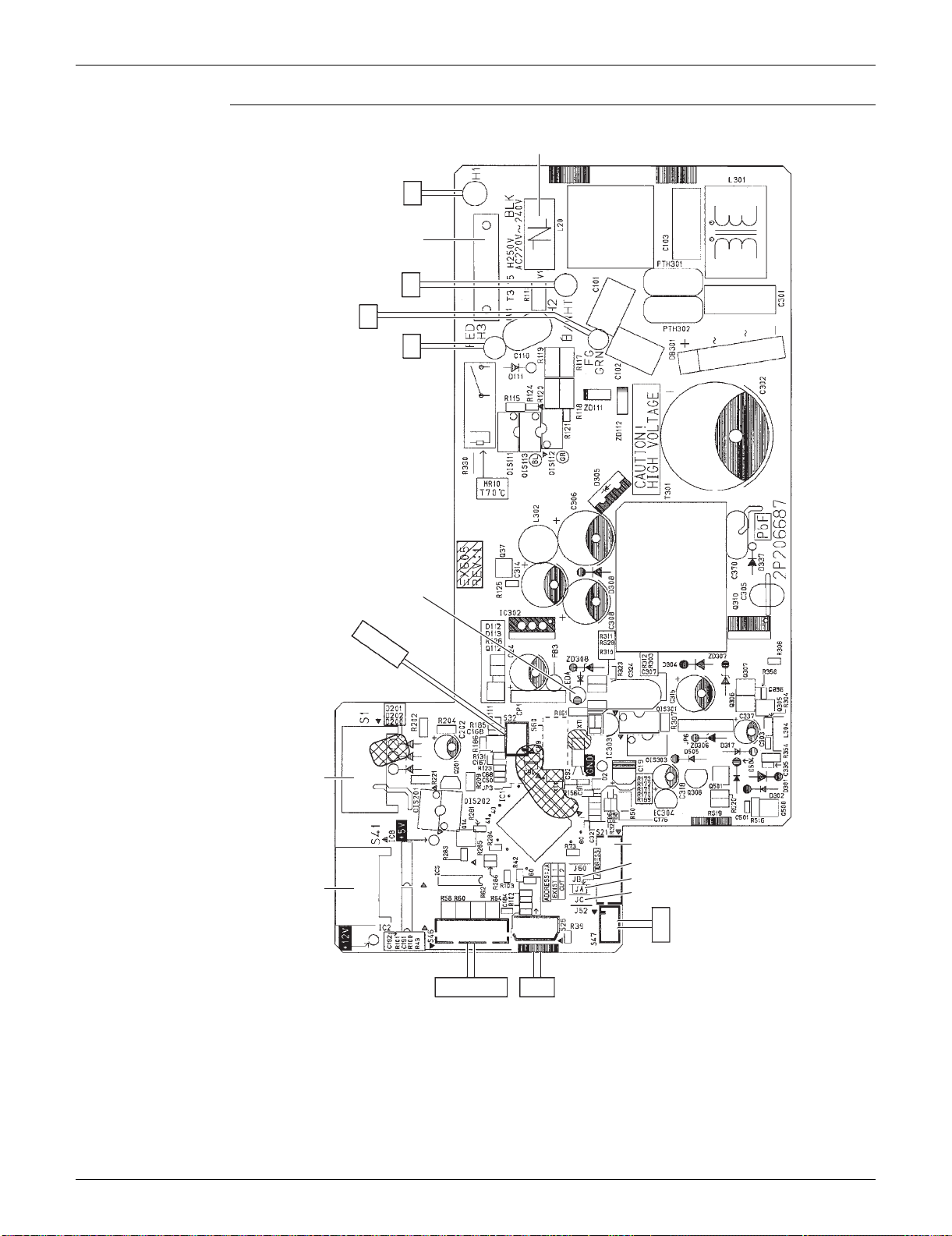
13 Printed Circuit Board Connector Wiring Diagram
1. Indoor Unit
1.1 FTXS09/12LVJU
Connectors and
Other Parts
PCB (1): Control PCB
PCB (2): Signal Receiver PCB
PCB (3): Display PCB
PCB (4): INTELLIGENT EYE Sensor PCB
1) S1 Connector for DC fan motor
2) S21 Connector for centralized control (HA)
3) S25 Connector for INTELLIGENT EYE sensor PCB
4) S32 Indoor heat exchanger thermistor
5) S41 Connector for swing motors
6) S46 Connector for display PCB
7) S47 Connector for signal receiver PCB
8) H1, H2, H3, FG Connector for terminal board
9) JA Address setting jumper
Refer to page 388 for detail.
10)JB Fan speed setting when compressor stops for thermostat OFF
JC Power failure recovery function (auto-restart)
Refer to page 390 for detail.
11)LED A LED for service monitor (green)
12)FU1 (F1U) Fuse (3.15 A, 250 V)
13) V1 Varistor
1) S48 Connector for control PCB
1) S49 Connector for control PCB
2) SW1 Forced cooling operation [ON/OFF] button
Refer to page 384 for detail.
3) LED1 (H1P) LED for operation (green)
4) LED2 (H2P) LED for timer (yellow)
5) LED3 (H3P) LED for INTELLIGENT EYE (green)
6) RTH1 (R1T) Room temperature thermistor
1) S26 Connector for control PCB
SiUS091133 Indoor Unit
Printed Circuit Board Connector Wiring Diagram 14
PCB Detail PCB (1): Control PCB
V1
FU1
S1
S41
S21
S47
JB
JA
JC
S46 S25
LED A
S32
FG
H1
H2
H3
2P206687-4
Indoor Unit SiUS091133
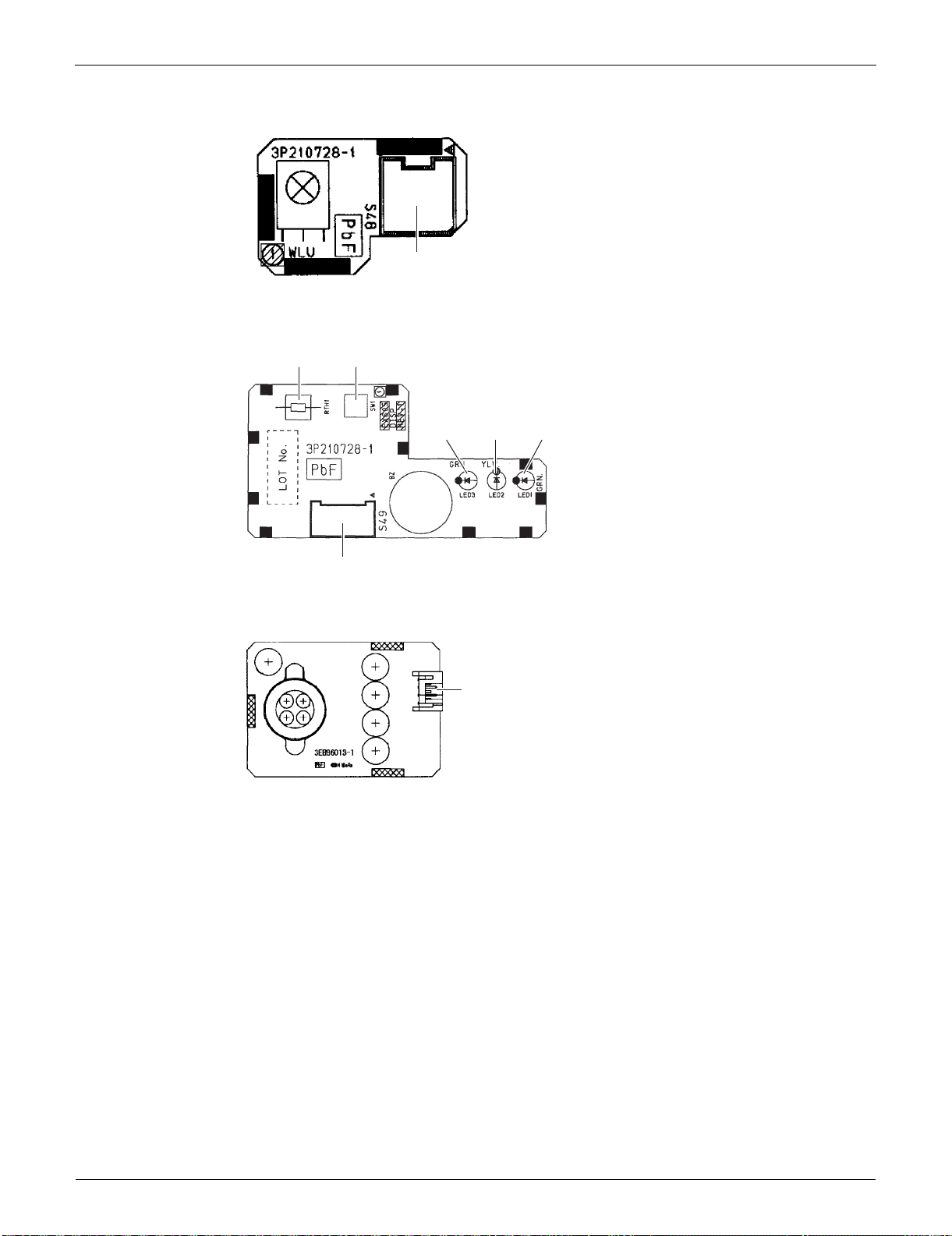
15 Printed Circuit Board Connector Wiring Diagram
PCB (2): Signal Receiver PCB
PCB (3): Display PCB
PCB (4): INTELLIGENT EYE Sensor PCB
3P210728-1
S48
3P210728-1
RTH1
SW1
S49
LED3 LED2 LED1
3EB86013-1
S26

SiUS091133 Indoor Unit
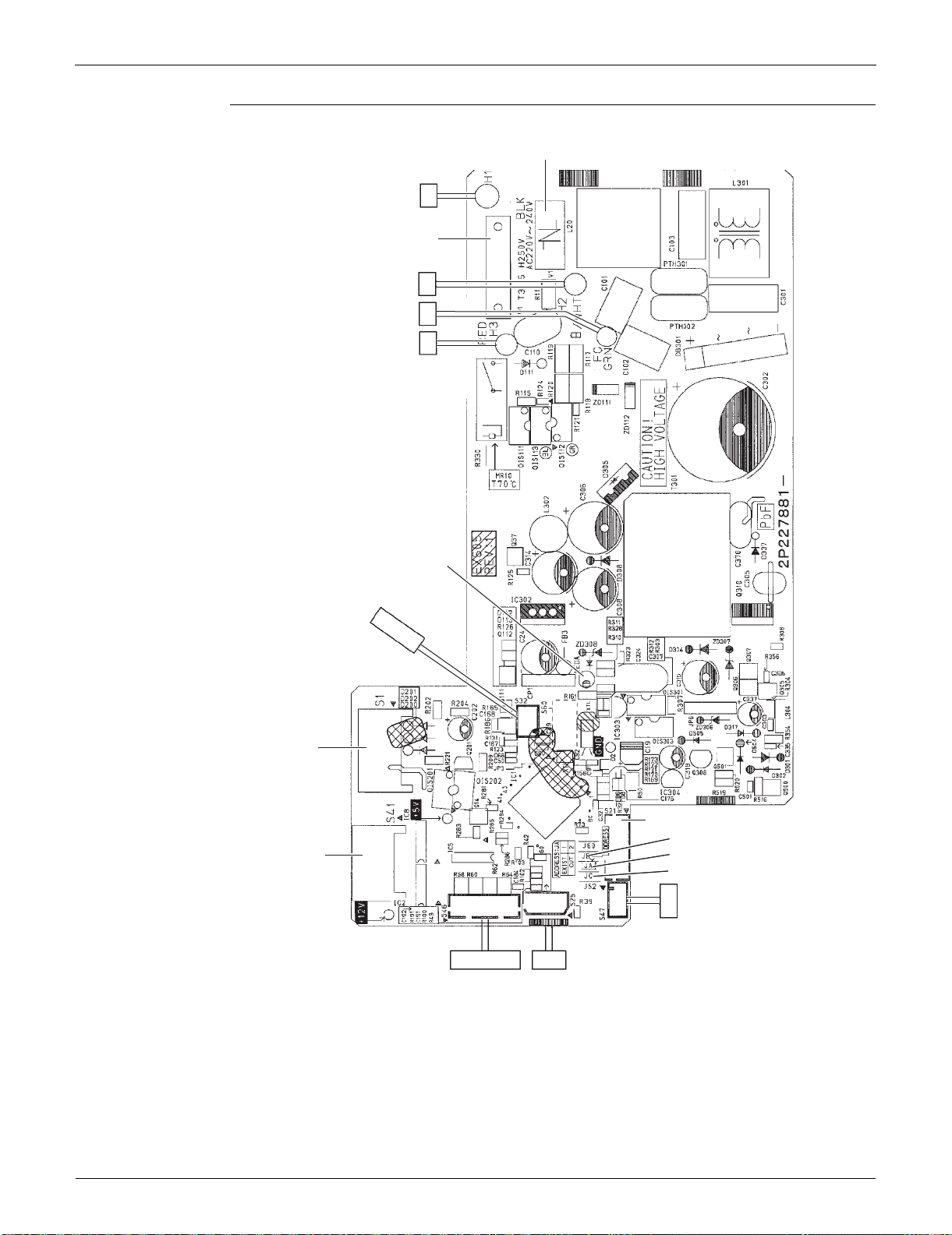
Printed Circuit Board Connector Wiring Diagram 16
1.2 FTXS15/18/24/30/36LVJU
Connectors and
Other Parts
PCB (1): Control PCB
PCB (2): Signal Receiver PCB
PCB (3): Display PCB
PCB (4): INTELLIGENT EYE Sensor PCB
1) S1 Connector for DC fan motor
2) S21 Connector for centralized control (HA)
3) S25 Connector for INTELLIGENT EYE sensor PCB
4) S32 Indoor heat exchanger thermistor
5) S41 Connector for swing motors
6) S46 Connector for display PCB
7) S47 Connector for signal receiver PCB
8) H1, H2, H3, FG Connector for terminal board
9) JA Address setting jumper
Refer to page 388 for detail.
10)JB Fan speed setting when compressor stops for thermostat OFF
JC Power failure recovery function (auto-restart)
Refer to page 390 for detail.
11)LED A LED for service monitor (green)
12)FU1 (F1U) Fuse (3.15 A, 250 V)
13) V1 Varistor
1) S48 Connector for control PCB
1) S49 Connector for control PCB
2) SW1 Forced cooling operation ON/OFF button
Refer to page 384 for detail.
3) LED1 (H1P) LED for operation (green)
4) LED2 (H2P) LED for timer (yellow)
5) LED3 (H3P) LED for INTELLIGENT EYE (green)
6) RTH1 (R1T) Room temperature thermistor
1) S36 Connector for control PCB
Indoor Unit SiUS091133
17 Printed Circuit Board Connector Wiring Diagram
PCB Detail PCB (1): Control PCB
2P227881-5
2P227881-6
V1
H1
H2
H3
LED A
S32
S1
S41
S46 S25
S47
S21
JB
JA
JC
FG
FU1
(3.15A)
SiUS091133 Indoor Unit
Printed Circuit Board Connector Wiring Diagram 18
PCB (2): Signal Receiver PCB
PCB (3): Display PCB
PCB (4): INTELLIGENT EYE Sensor PCB
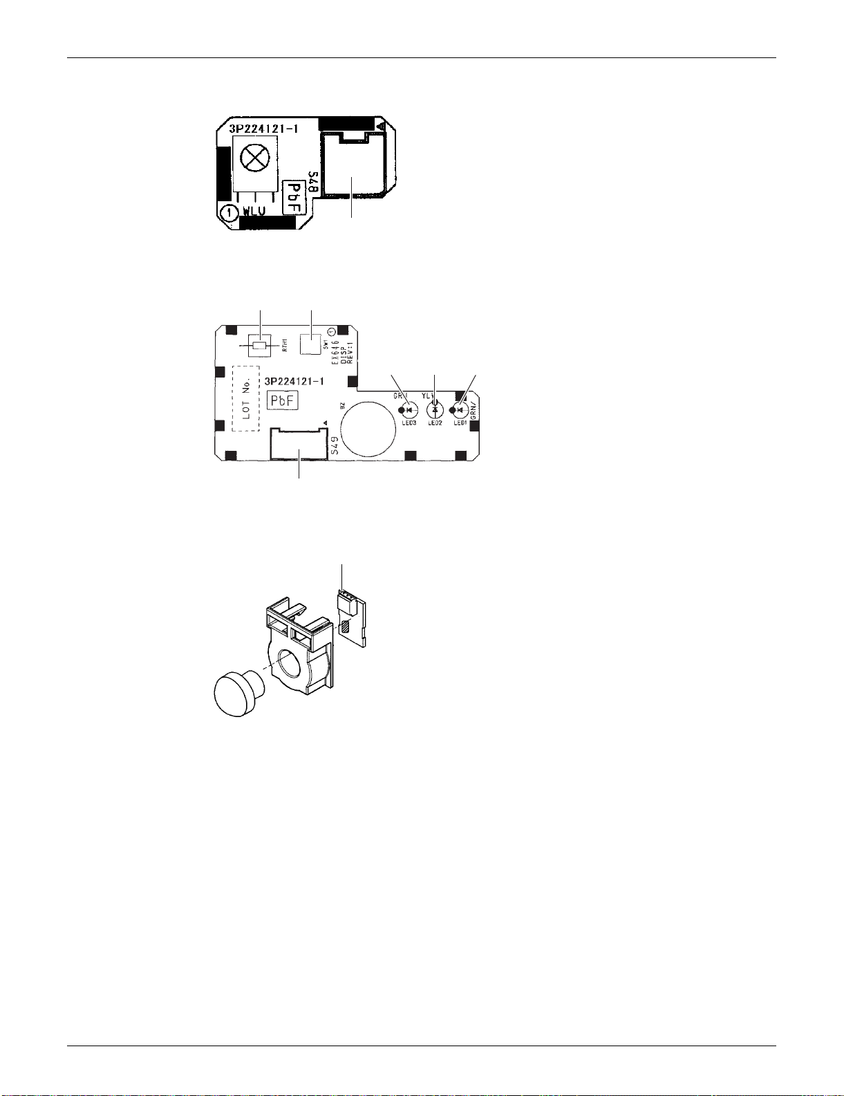
3P224121-1
S48
3P224121-1
RTH1 SW1
LED3
LED2
LED1
S49
S36
3P227885-1

Indoor Unit SiUS091133
19 Printed Circuit Board Connector Wiring Diagram
1.3 FDXS09/12LVJU
Connectors and
Other Parts
A1P: Control PCB
A2P: Display PCB
1) S1 Connector for AC fan motor
2) S7 Connector for AC fan motor (Hall IC)
3) S21 Connector for centralized control (HA)
4) S26 Connector for display PCB
5) S32 Connector for indoor heat exchanger thermistor
6) H1, H2, H3 Connector for terminal board
7) FG (GND) Connector for terminal board (ground)
8) JA Address setting jumper
Refer to page 388 for detail.
9) JB Fan speed setting when compressor stops for thermostat OFF
JC Power failure recovery function (auto-restart)
Refer to page 390 for detail.
10)LED A LED for service monitor (green)
11)FU1 (F1U) Fuse (3.15 A, 250 V)
12)V1 (V1TR) Varistor
1) S1 Connector for control PCB
2) SW1 (S1W) Forced cooling operation [ON/OFF] button
Refer to page 384 for detail.
3) LED2 (H2P) LED for timer (yellow)
4) LED3 (H3P) LED for operation (green)
5) RTH1 (R1T) Room temperature thermistor
SiUS091133 Indoor Unit
Printed Circuit Board Connector Wiring Diagram 20
PCB Detail A1P: Control PCB
A2P: Display PCB
LED 1 does not function.
H2
H1
H3
FG
JB
S21
2P292535-1
LED A JCJA
S7
S1
FU1
S26
V1
S32
S1
LED3
LED2
SW1
2P084375-1
RTH1
1

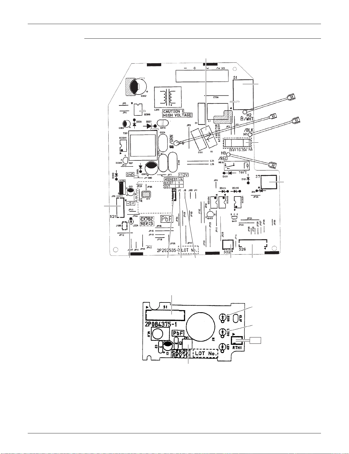
Outdoor Unit SiUS091133
21 Printed Circuit Board Connector Wiring Diagram
2. Outdoor Unit
2.1 RXS09/12LVJU
Connectors and
Other Parts
PCB (1): Filter PCB
PCB (2): Main PCB
PCB (3): Forced Operation Button PCB
1) S11 Connector for main PCB
2) AC1, AC2, S Connector for terminal board
3) E1, E2 Terminal for ground wire
4) HL2, HN2 Connector for main PCB
5) HR1 Connector for reactor
6) FU1 Fuse (3.15 A, 250 V)
7) FU3 Fuse (20 A, 250 V)
8) V2, V3 Varistor
1) S10 Connector for filter PCB
2) S20 Connector for electronic expansion valve coil
3) S40 Connector for overload protector
4) S70 Connector for fan motor
5) S80 Connector for four-way valve coil
6) S90 Connector for thermistors
(outdoor temperature, outdoor heat exchanger, discharge pipe)
7) S100 Connector for forced operation button PCB
8) HL3, HN3 Connector for filter PCB
9) HR2 Connector for reactor
10)U, V, W Connector for compressor
11)FU2 Fuse (3.15 A, 250 V)
12)LED A LED for service monitor (green)
13) V1 Varistor
14)J4 Jumper for facility setting
Refer to page 389 for detail.
1) S110 Connector for main PCB
2) SW1 Forced cooling operation [ON/OFF] button
Refer to page 384 for detail.
SiUS091133 Outdoor Unit
Printed Circuit Board Connector Wiring Diagram 22
PCB Detail PCB (1): Filter PCB
PCB (2): Main PCB
PCB (3): Forced Operation Button PCB
HR1
HL2
3P254234-7
FU1
HN2
S
FU3
AC2
E1, E2
AC1
S11
V3V2
S10
J4
S90
FU2
S100
2P290759-2
S70
S40
S20
S80
HL3
HN3
V1
LED A
UVW
HR2
SW1
S110
3P255755-2

Outdoor Unit SiUS091133
23 Printed Circuit Board Connector Wiring Diagram
2.2 RXS15/18LVJU
Connectors and
Other Parts
PCB (1): Filter PCB
PCB (2): Main PCB
1) S11 Connector for [S10] on main PCB
2) HL1, HN1, S Connector for terminal board
3) E1, E2 Terminal for ground wire
4) HL2, HN2 Connector for [HL3] [HN3] on main PCB
5) HL4, HN4 Connector for [S12] on main PCB
6) FU1 Fuse (3.15 A, 250 V)
7) FU3 Fuse (30 A, 250 V)
8) V2, V3 Varistor
9) SW1 Forced cooling operation [ON/OFF] button
Refer to page 384 for detail.
1) S10 Connector for [S11] on filter PCB
2) S12 Connector for [HL4] [HN4] on filter PCB
3) S20 Connector for electronic expansion valve coil
4) S40 Connector for overload protector
5) S70 Connector for fan motor
6) S80 Connector for four-way valve coil
7) S90 Connector for thermistors
(outdoor temperature, outdoor heat exchanger, discharge pipe)
8) HL3, HN3 Connector for [HL2] [HN2] on filter PCB
9) U, V, W Terminal for compressor
10)FU2 Fuse (3.15 A, 250 V)
11)LED A LED for service monitor (green)
12) V1 Varistor
13)J6 Jumper for facility setting
Refer to page 389 for detail.
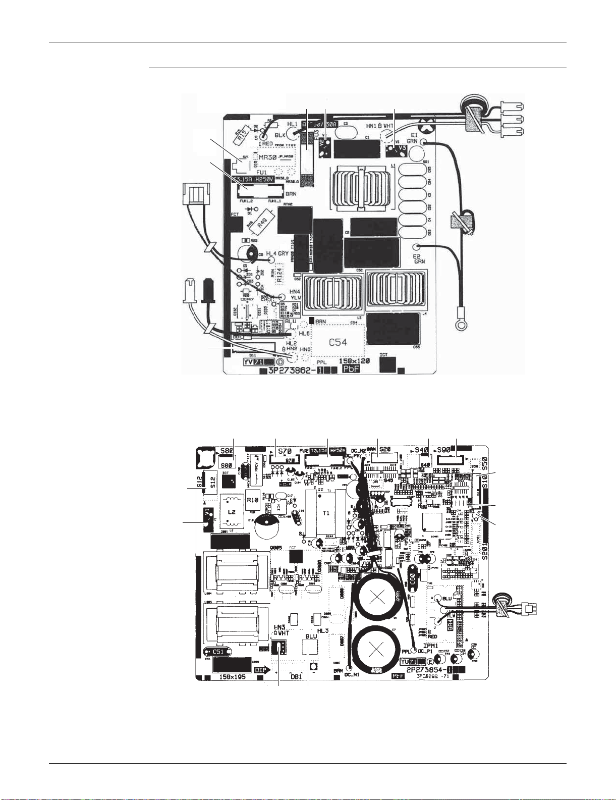
SiUS091133 Outdoor Unit
Printed Circuit Board Connector Wiring Diagram 24
PCB Detail PCB (1): Filter PCB
PCB (2): Main PCB
3P273862-3
SW1
S11
FU1
FU3 V2 V3
S
HL1
HN1
E2, E1
HN2 HL2
HN4, HL4
S80
S10
2P273854-5
S70 S20 S40 S90FU2
J6
LED A
U, V, W
HN3 HL3
S12
V1

Outdoor Unit SiUS091133
25 Printed Circuit Board Connector Wiring Diagram
2.3 RXS24LVJU, RK(X)S30/36LVJU
Connectors and
Other Parts
PCB (1): Main PCB
PCB (2): Service Monitor PCB
1) S10 Connector for terminal board (indoor - outdoor transmission)
2) S20 Connector for electronic expansion valve coil
3) S40 Connector for overload protector
4) S51, S101 Connector for service monitor PCB
5) S70 Connector for fan motor
6) S80 Connector for four-way valve coil
7) S90 Connector for thermistors
(outdoor temperature, outdoor heat exchanger, discharge pipe)
8) AC1, AC2 Connector for terminal board (power supply)
9) HR1, HR2 Connector for reactor
10)E1, E2 Connector for ground wire
11)U, V, W Connector for compressor
12)FU1 Fuse (30 A, 250 V)
13)FU2, FU3 Fuse (3.15 A, 250 V)
14) V2, V3, V5
V9, V100
Varistor
1) S52, S102 Connector for main PCB
2) LED A LED for service monitor (green)
3) SW1 Forced cooling operation [ON/OFF] button
Refer to page 384 for detail.
4) SW4-B Switch for facility setting
Refer to page 389 for detail.
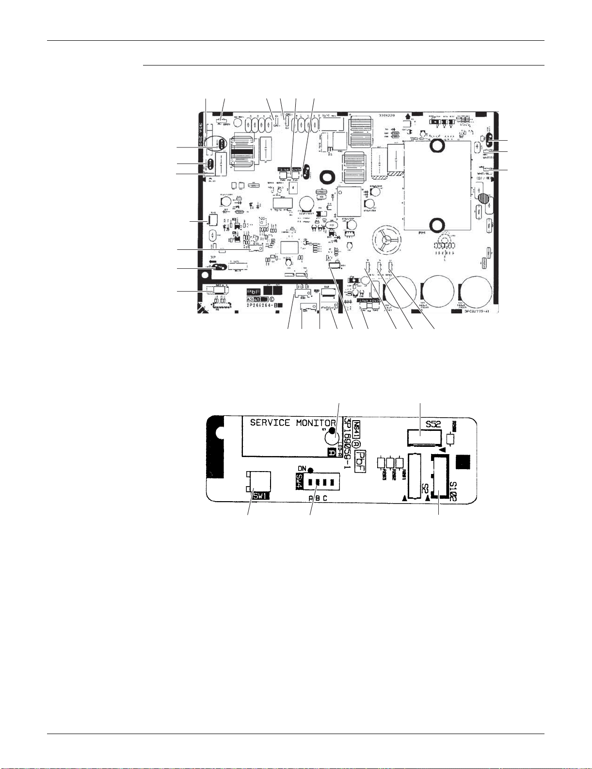
SiUS091133 Outdoor Unit
Printed Circuit Board Connector Wiring Diagram 26
PCB Detail PCB (1): Main PCB
PCB (2): Service Monitor PCB
SW4-A and SW4-C has no function and keep it off.
V3FU1 E1 E2 FU2
V100
HR1
FU3
2P266264-5
2P266264-6
S40S20 S70S90 S51 WV U
S10
AC2
S101
V5
S80
V9
V2
AC1
HR2
S102
SW1
3P169059-1
LED A
SW4-B
S52

SiUS091133
27 Function and Control
Part 4
Function and Control
1. Main Functions..........................................................................................28
1.1 Temperature Control..................................................................................28
1.2 Frequency Principle....................................................................................28
1.3 Airflow Direction Control (FTXS Series).....................................................30
1.4 Fan Speed Control for Indoor Unit .............................................................32
1.5 Program Dry Operation..............................................................................33
1.6 Automatic Operation...................................................................................34
1.7 Thermostat Control.....................................................................................35
1.8 NIGHT SET Mode......................................................................................36
1.9 ECONO Operation .....................................................................................37
1.10 INTELLIGENT EYE Operation (FTXS Series) ........................................... 38
1.11 Inverter POWERFUL Operation.................................................................39
1.12 Other Functions..........................................................................................40
2. Function of Thermistor..............................................................................41
3. Control Specification.................................................................................42
3.1 Mode Hierarchy..........................................................................................42
3.2 Frequency Control......................................................................................43
3.3 Controls at Mode Changing / Start-up........................................................45
3.4 Discharge Pipe Temperature Control.........................................................46
3.5 Input Current Control..................................................................................47
3.6 Freeze-up Protection Control.....................................................................48
3.7 Heating Peak-cut Control...........................................................................48
3.8 Outdoor Fan Control...................................................................................49
3.9 Liquid Compression Protection Function....................................................49
3.10 Defrost Control...........................................................................................50
3.11 Electronic Expansion Valve Control...........................................................51
3.12 Malfunctions...............................................................................................54
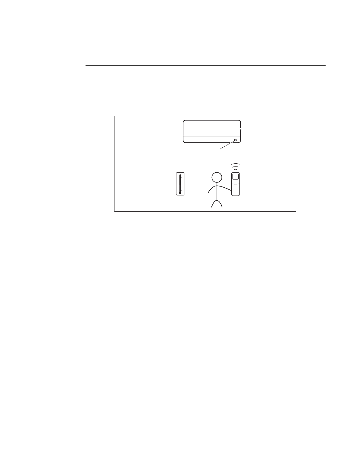
SiUS091133 Main Functions
Function and Control 28
1. Main Functions
1.1 Temperature Control
Definitions of
Temperatures
The definitions of temperatures are classified as following.
Room temperature: temperature of lower part of the room
Set temperature: temperature set by remote controller
Room thermistor temperature: temperature detected by room temperature thermistor
Target temperature: temperature determined by microcomputer
The illustration is for FTXS series as representative.
Temperature
Control
The temperature of the room is detected by the room temperature thermistor. However, there is
difference between the “temperature detected by room temperature thermistor” and the
“temperature of lower part of the room”, depending on the type of the indoor unit or installation
condition. Practically, the temperature control is done by the “target temperature appropriately
adjusted for the indoor unit” and the “temperature detected by room temperature thermistor”.
1.2 Frequency Principle
Main Control
Parameters
The compressor is frequency-controlled during normal operation. The target frequency is set by the
following 2 parameters coming from the operating indoor unit:
The load condition of the operating indoor unit
The difference between the room thermistor temperature and the target temperature
Additional
Control
Parameters
The target frequency is adapted by additional parameters in the following cases:
Frequency restrictions
Initial settings
Forced cooling operation
Target temperature
Set temperature
Room temperature
Room thermistor temperature
(R12321)
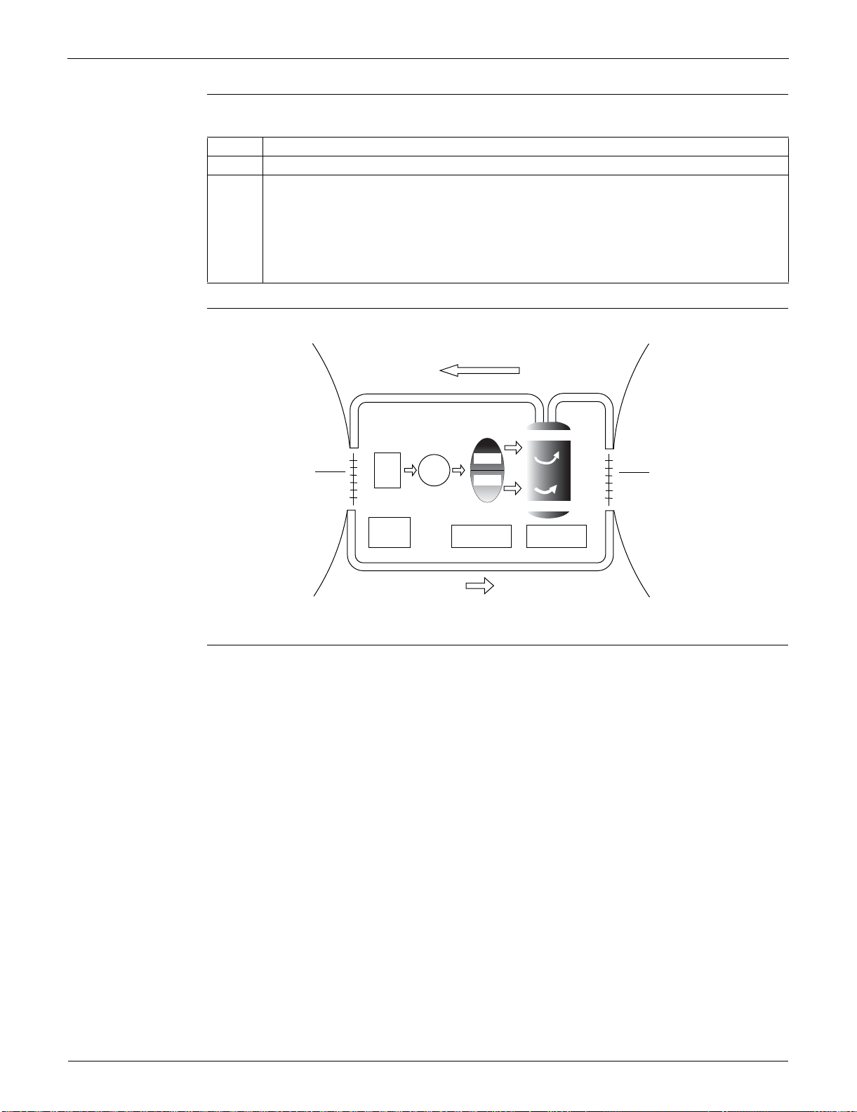
Main Functions SiUS091133
29 Function and Control
Inverter Principle To regulate the capacity, a frequency control is needed. The inverter makes it possible to alter the
rotation speed of the compressor. The following table explains the conversion principle:
Drawing of
Inverter
The following drawing shows a schematic view of the inverter principle:
Inverter Features The inverter provides the following features:
The regulating capacity can be changed according to the changes in the outdoor temperature
and cooling / heating load.
Quick heating and quick cooling
The compressor rotational speed is increased when starting the heating (or cooling). This
enables to reach the set temperature quickly.
Even during extreme cold weather, high capacity is achieved. It is maintained even when the
outdoor temperature is 2°C (35.6°F).
Comfortable air conditioning
A fine adjustment is integrated to keep the room temperature constant.
Energy saving heating and cooling
Once the set temperature is reached, the energy saving operation enables to maintain the room
temperature at low power.
Phase Description
1 The supplied AC power source is converted into the DC power source for the present.
2 The DC power source is reconverted into the three phase AC power source with variable
frequency.
When the frequency increases, the rotation speed of the compressor increases resulting in
an increased refrigerant circulation. This leads to a higher amount of the heat exchange per
unit.
When the frequency decreases, the rotation speed of the compressor decreases resulting
in a decreased refrigerant circulation. This leads to a lower amount of the heat exchange
per unit.
Refrigerant circulation rate (high)
high f
low f
freq=variable
Refrigerant circulation rate (low)
high speed
low speed
(R2812)
Amount of heat
exchanged air (large)
freq=
constant
50 Hz
60 Hz
capacity=
variable
Amount of heat
exchanged air (small)
AC
power
DC
power
Amount of heat
exchanged air (large)
Amount of heat
exchanged air (small)
SiUS091133 Main Functions
Function and Control 30
Frequency Limits The following functions regulate the minimum and maximum frequency:
Forced Cooling
Operation
Refer to page 384 for detail.
1.3 Airflow Direction Control (FTXS Series)
Power-Airflow
Dual Louvers
The large louver sends a large volume of air downward to the floor and provides an optimum
control in cooling, dry, and heating operation.
<Cooling / Dry>
During cooling or dry operation, the louver retracts into the indoor unit. Then, cool air can be blown
far and distributed all over the room.
<Heating>
During heating operation, the large louver directs airflow downward to spread the warm air to the
entire room.
Wide-Angle Fins The fins, made of elastic synthetic resin, provide a wide range of airflow that guarantees
comfortable air distribution.
Auto-Swing The following table explains the auto swing process for cooling, dry, heating, and fan:
Frequency Functions
Low Four-way valve operation compensation. Refer to page 45.
High Compressor protection function. Refer to page 46.
Discharge pipe temperature control. Refer to page 46.
Input current control. Refer to page 47.
Freeze-up protection control. Refer to page 48.
Heating peak-cut control. Refer to page 48.
Defrost control. Refer to page 50.
Vertical Swing (up and down)
Horizontal Swing
(right and left)
Cooling / Dry Heating Fan
09/12 class
15/18/24/30/36
class
15˚
45˚
35˚
55˚
(R13527)
30˚
70˚
30˚
65˚
(R11402)
5˚
80˚
30˚
65˚
(R11403)
45˚
45˚
(R11404)
(R9303)
60
°
50
°
25
°
15
°
(R9304)
70
°
40
°
75
°
30
°
(R9305)
75
°
15
°
25
°
70
°
(R9306)
45
°
45
°
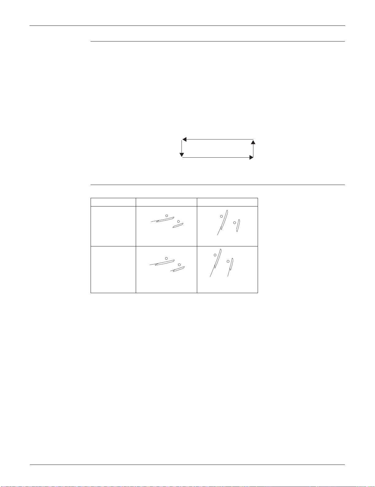
Main Functions SiUS091133
31 Function and Control
3-D Airflow Alternative repetition of vertical and horizontal swing motions enables uniform airconditioning of the
entire room. This function is effective for starting the air conditioner.
When the horizontal swing and vertical swing are both set to automatic operation, the airflow
becomes 3-D airflow. The horizontal and vertical swing motion is altered and the airflow direction
changes in the order shown in the following diagram.
(1) The vertical blades (fins) move from the right to the left.
(2) The horizontal blades (louvers) move downward.
(3) The vertical blades (fins) move from the left to the right.
(4) The horizontal blades (louvers) move upward.
COMFORT
AIRFLOW
Operation
The horizontal blades (louvers) are controlled not to blow the air directly at the people in the room.
(R13554)
(1)
(4)(3)
(2)
Cooling Heating
09/12 class
15/18/24/30/36
class
(R4302)
8˚
(R8413)
80˚
(R9655)
10
°
10
°
(R9654)
75
°
80
°
SiUS091133 Main Functions
Function and Control 32
1.4 Fan Speed Control for Indoor Unit
Outline Phase control and fan speed control contains 9 steps: LLL, LL, SL, L, ML, M, MH, H, and HH.
The airflow rate can be automatically controlled depending on the difference between the room
thermistor temperature and the target temperature. This is done through phase control and Hall IC
control.
For more information about Hall IC, refer to the troubleshooting for fan motor on page 99.
Automatic Fan
Speed Control
In automatic fan speed operation, the step “SL” is not available.
= The airflow rate is automatically controlled within this range when the FAN setting button
is set to automatic
.
<Cooling>
The following drawing explains the principle of fan speed control for cooling.
*For FTXS series, the upper limit is M tap in 30 minutes from the operation start.
<Heating>
In heating operation, the fan speed is regulated according to the indoor heat exchanger
temperature and the difference between the room thermistor temperature and the target
temperature.
Note: 1. During POWERFUL operation, the fan rotates at H tap + 50 rpm.
2. The fan stops during defrost operation.
COMFORT
AIRFLOW
Operation
FTXS series
The fan speed is controlled automatically within the following steps.
<Cooling>
L tap ~ MH tap (same as AUTOMATIC)
<Heating>
ML tap ~ MH tap
The latest command has the priority between POWERFUL and COMFORT AIRFLOW.
Step Cooling Heating
LLL
LL
L
ML
M
MH
H
HH (POWERFUL)
(R11681)
(R6834)
(R16967)
Room thermistor temperature – target temperature
MH*
M
ML
L
+3˚C (+5.4˚F)
+2˚C (+3.6˚F)
+1˚C (+1.8˚F)
Fan speed
+2.5˚C (+4.5˚F)
+1.5˚C (+2.7˚F)
+0.5˚C (+0.9˚F)
Main Functions SiUS091133
33 Function and Control
1.5 Program Dry Operation
Outline Program dry operation removes humidity while preventing the room temperature from lowering.
Since the microcomputer controls both the temperature and airflow rate, the temperature
adjustment and [FAN] setting buttons are inoperable.
Detail The microcomputer automatically sets the temperature and airflow rate. The difference between
the room thermistor temperature at start-up and the target temperature is divided into two zones.
Then, the unit operates in an appropriate capacity for each zone to maintain the temperature and
humidity at a comfortable level.
Room thermistor
temperature at start-up
Target temperature
X
Thermostat OFF point
Y
Thermostat ON point
Z
24°C (75.2°F) or more
Room thermistor
temperature at start-up
X
– 2.5°C (–4.5°F)
X – 0.5°C (– 0.9°F)
or
Y + 0.5°C (0.9°F) (zone
B) continues for 10 min.
23.5°C (74.3°F)
X – 2.0°C (–3.6°F)
X – 0.5°C (– 0.9°F)
or
Y + 0.5°C (0.9°F) (zone
B) continues for 10 min.
~
18°C (64.4°F)
18°C (64.4°F) X
– 2.0°C (–3.6°F)
X – 0.5°C (– 0.9°F) = 17.5°C (63.5°F)
or
Y + 0.5°C (0.9°F) (zone
B) continues for 10 min.
17.5°C (63.5°F)
~
Z
X
Y
Zone B
Zone B
Zone A = Thermostat OFF
Zone C = Thermostat ON
+ 0.5˚C (0.9˚F)
(R11587)
SiUS091133 Main Functions
Function and Control 34
1.6 Automatic Operation
Outline Automatic Cooling / Heating Function
When the automatic operation is selected with the remote controller, the microcomputer
automatically determines the operation mode as cooling or heating according to the room
temperature and the set temperature at start-up.
The unit automatically switches the operation mode to maintain the room temperature at the set
temperature.
Detail Ts: set temperature (set by remote controller)
Tt: target temperature (determined by microcomputer)
Tr: room thermistor temperature (detected by room temperature thermistor)
C: correction value
1. The set temperature (Ts) determines the target temperature (Tt).
(Ts = 18 ~ 30°C, 64.4 ~ 86°F).
2. The target temperature (Tt) is calculated as;
Tt = Ts + C
where C is the correction value
.
C = 0°C (0°F)
3. Thermostat ON/OFF point and operation mode switching point are as follows.
(1) Heating Cooling switching point:
Tr Tt + 3.0°C (+5.4°F) (FTXS series)
Tr Tt + 2.5°C (+4.5°F) (FDXS series)
(2) Cooling Heating switching point:
Tr < Tt – 2.5°C (–4.5°F)
(3) Thermostat ON/OFF point is the same as the ON/OFF point of cooling or heating operation.
4. During initial operation
Tr Ts : Cooling operation
Tr < Ts : Heating operation
FTXS series
Ex: When the target temperature is 25°C (77°F)
Cooling 23°C (73.4°F): Thermostat OFF 22°C (71.6°F): Switch to heating
Heating 27°C (80.6°F): Thermostat OFF 28°C (82.4°F): Switch to cooling
FDXS series
Ex: When the target temperature is 25°C (77°F)
Cooling 23°C (73.4°F): Thermostat OFF 22°C (71.6°F): Switch to heating
Heating 26.5°C (79.7°F): Thermostat OFF 27.5°C (81.5°F): Switch to cooling
Target temperature + 3.0˚C (+5.4˚F)
Heating Operation
Target temperature – 2.5˚C (–4.5˚F)
Cooling Operation
(R16965)
Target temperature – 2.0˚C (–3.6˚F)
= Thermostat OFF
Target temperature + 2.0˚C (+3.6˚F)
= Thermostat OFF
Target temperature + 2.5˚C (+4.5˚F)
Heating Operation
Target temperature – 2.5˚C (–4.5˚F)
Cooling Operation
(R16966)
Target temperature – 2.0˚C (–3.6˚F)
= Thermostat OFF
Target temperature + 1.5˚C (+2.7˚F)
= Thermostat OFF
Main Functions SiUS091133
35 Function and Control
1.7 Thermostat Control
Thermostat control is based on the difference between the room thermistor temperature and the
target temperature.
Thermostat OFF Condition
The temperature difference is in the zone A.
Thermostat ON Condition
The temperature difference returns to the zone C after being in the zone A.
The system resumes from defrost control in any zones except A.
The operation turns on in any zones except A.
The monitoring time has passed while the temperature difference is in the zone B.
(Cooling / Dry: 10 minutes, Heating: 10 seconds)
<Cooling / Dry>
FTXS series
FDXS series
<Heating>
Refer to “Temperature Control” on page 28 for detail.
B
A
OFF
ON
C
Room thermistor temperature – target temperature
–1.5˚C (–2.7˚F)
(R14452)
Cooling : –0.5˚C (–0.9˚F)
Dry : –0.5˚C (–0.9˚F)
Cooling : –2.0˚C (–3.6˚F)
Dry : –2.5 ~ –2.0˚C (–4.5 ~ –3.6˚F)
B
A
OFF
ON
C
Room thermistor temperature – target temperature
–1.5˚C (–2.7˚F)
(R16693)
Cooling : –1.0˚C (–1.8˚F)
Dry : –1.0˚C (–1.8˚F)
Cooling : –2.0˚C (–3.6˚F)
Dry : –2.5 ~ –2.0˚C (–4.5 ~ –3.6˚F)
B
B
A
A
OFF
OFF
ONON
CC
2.0˚C (3.6˚F)
0.5˚C (0.9˚F)
1.5˚C (2.7˚F)
Room thermistor temperature – target temperature
(R14451)
SiUS091133 Main Functions
Function and Control 36
1.8 NIGHT SET Mode
Outline When the OFF timer is set, the NIGHT SET Mode is automatically activated. The NIGHT SET
Mode keeps the airflow rate setting.
Detail The NIGHT SET Mode continues operation at the target temperature for the first one hour, then
automatically raises the target temperature slightly in the case of cooling, or lowers it slightly in the
case of heating. This prevents excessive cooling in summer and excessive heating in winter to
ensure comfortable sleeping conditions, and also conserves electricity.
<Cooling>
<Heating>
(R14453)
TIMER operation
NIGHT SET Mode ON
Target temperature
+0.5˚C (+0.9˚F)
temperature shift
Operation stops
at the set hours
1 hour
0.5˚C (0.9˚F)
2˚C (3.6˚F)
(R14454)
Target temperature
1 hour later
TIMER operation
NIGHT SET Mode ON
Main Functions SiUS091133
37 Function and Control
1.9 ECONO Operation
Outline ECONO operation reduces the maximum operating current and the power consumption.
This operation is particularly convenient for energy-saving-oriented users. It is also a major bonus
for those whose breaker capacities do not allow the use of multiple electrical devices and air
conditioners.
It is easily activated from the wireless remote controller by pushing the [ECONO] button.
When this function is activated, the maximum capacity also decreases.
The remote controller can send the ECONO command when the unit is in COOL, HEAT, DRY, or
AUTO operation. This function can only be set when the unit is running. Pressing the [ON/OFF]
button on the remote controller cancels the function.
This function and POWERFUL operation cannot be used at the same time. The latest command
has the priority.
ECONO Operation
(R9288)
Normal
Maximum during normal operation
Maximum during ECONO operation
Time
Power
consumption
and current
SiUS091133 Main Functions
Function and Control 38
1.10 INTELLIGENT EYE Operation (FTXS Series)
Outline This function detects the existence of humans in the room with a motion sensor (INTELLIGENT
EYE) and reduces the capacity when there is nobody in the room in order to save electricity.
Detail 1. Detection method by INTELLIGENT EYE
This sensor detects human motion by receiving infrared rays and displays the pulse wave
output.
The microcomputer in the indoor unit carries out a sampling every 20 msec. and if it detects 10
cycles of the wave in 1 second in total (corresponding to 20 msec. × 10 = 200 msec.), it judges
humans are in the room as the motion signal is ON.
2. The motions (for example: in cooling)
When the microcomputer does not have a signal from the sensor in 20 minutes, it judges that
nobody is in the room and operates the unit at a temperature shifted from the target
temperature. (Cooling / Dry: 1 ~ 2°C (1.8 ~ 3.6°F) higher, Heating: 2°C (3.6°F) lower, Auto:
according to the operation mode at that time.)
In FAN operation, the fan speed is reduced by 60 rpm.
Others For dry operation, you cannot set the temperature with a remote controller, but the target
temperature is shifted internally.
1 sec.
sampling (20 msec.)
High
Low
ON
OFF
Sensor output
(Human motion)
(R2821)
Human detection
signal
If the sensor detects the outputs
10 times/sec. or more, it judges
humans exist.
ON
OFF
RESET.
20 min. 20 min.within 20 min.
ON
OFF
ON
OFF
Operation
OFF
Fan speed ()
Set speed Set speed
Target temperature
(R14583)
Remote controller
INTELLIGENT
EYE button
Human detection
signal
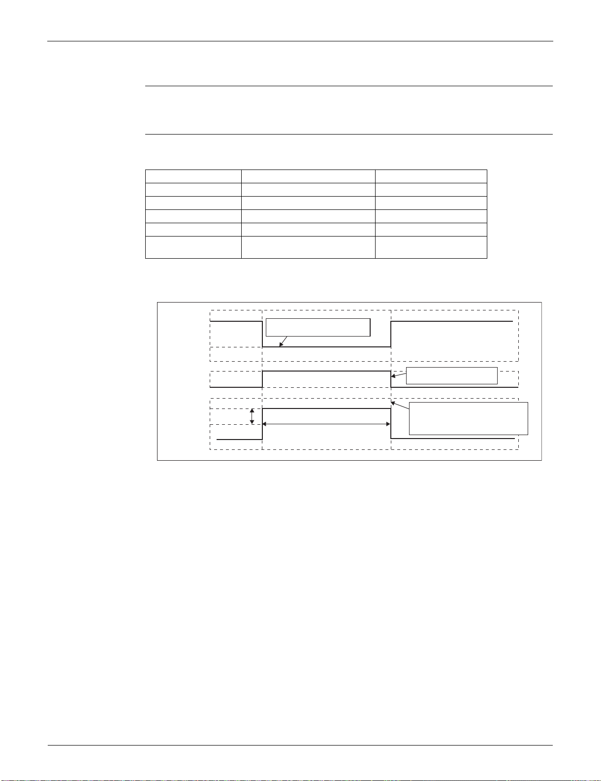
Main Functions SiUS091133
39 Function and Control
1.11 Inverter POWERFUL Operation
Outline In order to exploit the cooling and heating capacity to full extent, operate the air conditioner by
increasing the indoor fan rotating speed and the compressor frequency.
Detail When [POWERFUL] button is pressed, the fan speed and target temperature are converted to the
following states for 20 minutes.
A = 50 rpm
Ex: POWERFUL operation in cooling
Operation mode Fan speed Target temperature
COOL H tap + A rpm 18°C (64.4°F)
DRY Dry rotating speed + A rpm Lowered by 2.5°C (4.5°F)
HEAT H tap + A rpm 30 ~ 31.5°C (86 ~ 88.7°F)
FAN H tap + A rpm —
AUTO Same as cooling / heating in
POWERFUL operation
The target temperature is
kept unchanged.
(R13571)
Target temp.
Fan
A rpm
18˚C (64.4˚F)
H tap
Set tap
20 minutes
It should be the lower limit of
cooling temperature.
It counts 20 minutes. also
in the remote controller.
POWERFUL
ON
POWERFUL
OFF
Ending condition: "or" in 1 to 3
1. After the lapse of 20 minutes.
2. Operation OFF
3. POWERFUL operation is OFF.
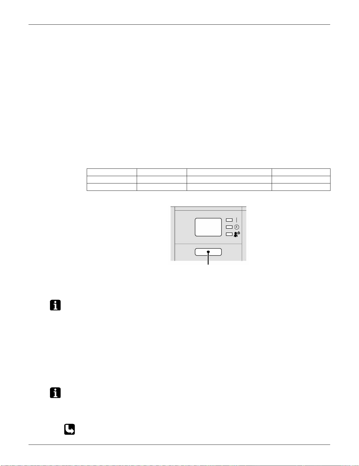
SiUS091133 Main Functions
Function and Control 40
1.12 Other Functions
1.12.1 Hot-Start Function
In order to prevent the cold air blast that normally comes when heating operation is started, the
temperature of the indoor heat exchanger is detected, and the airflow is either stopped or made
very weak thereby carrying out comfortable heating of the room.
*The cold air blast is also prevented using similar control when the defrosting operation is started or
when the thermostat is turned ON.
1.12.2 Signal Receiving Sign
When the indoor unit receives a signal from the remote controller, the unit emits a signal receiving
sound.
1.12.3 Indoor Unit ON/OFF Button
An [ON/OFF] button is provided on the display of the unit.
Press the [ON/OFF] button once to start operation. Press once again to stop it.
The [ON/OFF] button is useful when the remote controller is missing or the battery has run out.
The operation mode refers to the following table.
Ex: FTXS series
<Forced cooling operation>
Forced cooling operation can be started by pressing the [ON/OFF] button for 5 to 9 seconds while
the unit is not operating.
Refer to page 384 for detail.
Note: When the [ON/OFF] button is pressed for 10 seconds or more, the forced cooling operation is
stopped.
1.12.4 Titanium Apatite Photocatalytic Air-Purifying Filter
This filter combines the Air-Purifying Filter and Titanium Apatite Photocatalytic Deodorizing Filter as
a single highly effective filter. The filter traps microscopic particles, decomposes odors and even
deactivates bacteria and viruses. It lasts for 3 years without replacement if washed about once
every 6 months.
1.12.5 Auto-restart Function
If a power failure (including one for just a moment) occurs during the operation, the operation
restarts automatically when the power is restored in the same condition as before the power failure.
Note: It takes 3 minutes to restart the operation because the 3-minute standby function is activated.
1.12.6 WEEKLY TIMER Operation
Up to 4 timer settings can be saved for each day of the week (up to 28 settings in total).
Those 3 items of “ON/OFF”, “temperature” and “time” can be set.
Refer to page 71 for detail.
Operation mode Temperature setting Airflow rate
Cooling Only COOL 22°C (71.6°F) Automatic
Heat Pump AUTO 25°C (77°F) Automatic
ON/OFF button
(R13555)
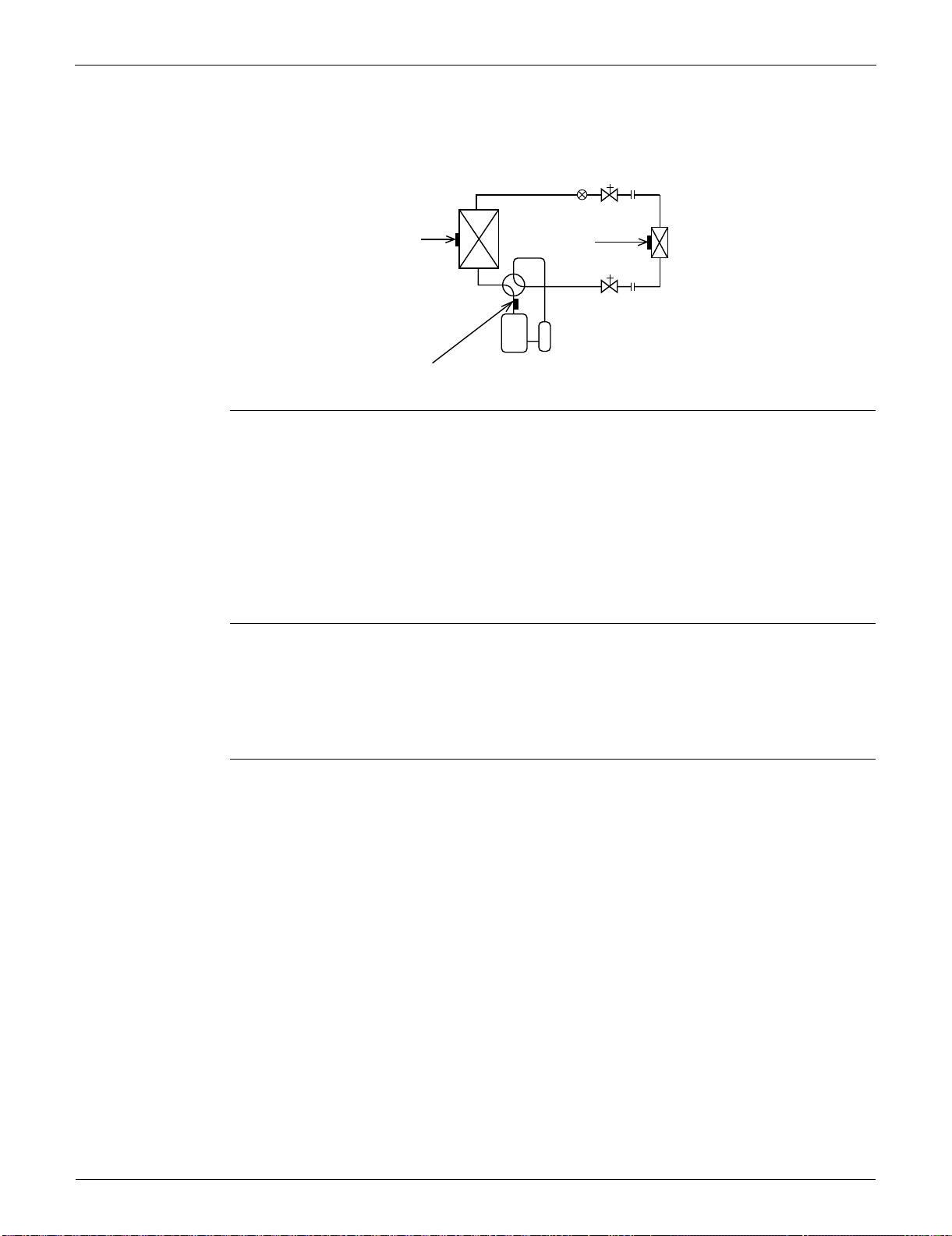
Function of Thermistor SiUS091133
41 Function and Control
2. Function of Thermistor
(1) Outdoor Heat
Exchanger
Thermistor
1. The outdoor heat exchanger thermistor is used for controlling the target discharge pipe
temperature. The system sets the target discharge pipe temperature according to the outdoor
and indoor heat exchanger temperature, and controls the electronic expansion valve opening so
that the target discharge pipe temperature can be obtained.
2. In cooling operation, the outdoor heat exchanger thermistor is used for detecting the
disconnection of the discharge pipe thermistor. When the discharge pipe temperature becomes
lower than the outdoor heat exchanger temperature, the discharge pipe thermistor is judged as
disconnected.
3. In cooling operation, the outdoor heat exchanger thermistor is used for high pressure protection.
(2) Discharge
Pipe Thermistor
1. The discharge pipe thermistor is used for controlling discharge pipe temperature. If the
discharge pipe temperature (used in place of the inner temperature of the compressor) rises
abnormally, the operating frequency becomes lower or the operation halts.
2. The discharge pipe thermistor is used for detecting disconnection of the discharge pipe
thermistor.
(3) Indoor Heat
Exchanger
Thermistor
1. The indoor heat exchanger thermistor is used for controlling the target discharge pipe
temperature. The system sets the target discharge pipe temperature according to the outdoor
and indoor heat exchanger temperature, and controls the electronic expansion valve opening so
that the target discharge pipe temperature can be obtained.
2. In cooling operation, the indoor heat exchanger thermistor is used for freeze-up protection
control. If the indoor heat exchanger temperature drops abnormally, the operating frequency
becomes lower or the operation halts.
3. In heating operation, the indoor heat exchanger thermistor is used for detecting the
disconnection of the discharge pipe thermistor. When the discharge pipe temperature becomes
lower than the indoor heat exchanger temperature, the discharge pipe thermistor is judged as
disconnected.
Four way valve
Compressor
(R14247)
(3)
(2)
Electronic
expansion valve
(1)
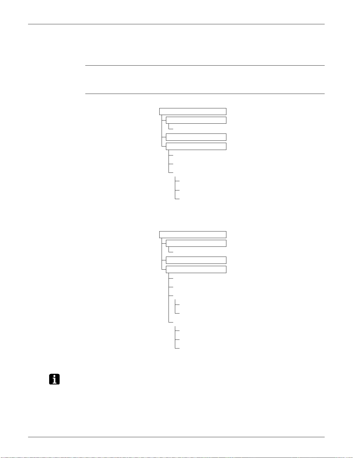
SiUS091133 Control Specification
Function and Control 42
3. Control Specification
3.1 Mode Hierarchy
Outline There are 3 modes; normal operation mode, forced operation mode and the power transistor test
mode for installation and servicing.
Detail Cooling Only Model
Heat Pump Model
Note: Unless specified otherwise, an indoor dry operation command is regarded as cooling operation.
(R14428)
Air conditioner control mode
Forced operation mode
Forced cooling operation
Power transistor test mode
Normal operation mode
Fan
Cooling (includes drying)
Stop (indoor unit: OFF)
Preheating operation
Discharging from capacitor
Stop
Air conditioner control mode
Forced operation mode
Forced cooling operation
Power transistor test mode
Normal operation mode
Fan
Cooling (includes drying)
Heating
Heating
Defrosting
Stop (indoor unit: OFF)
Preheating operation
Discharging from capacitor
Stop
(R14248)
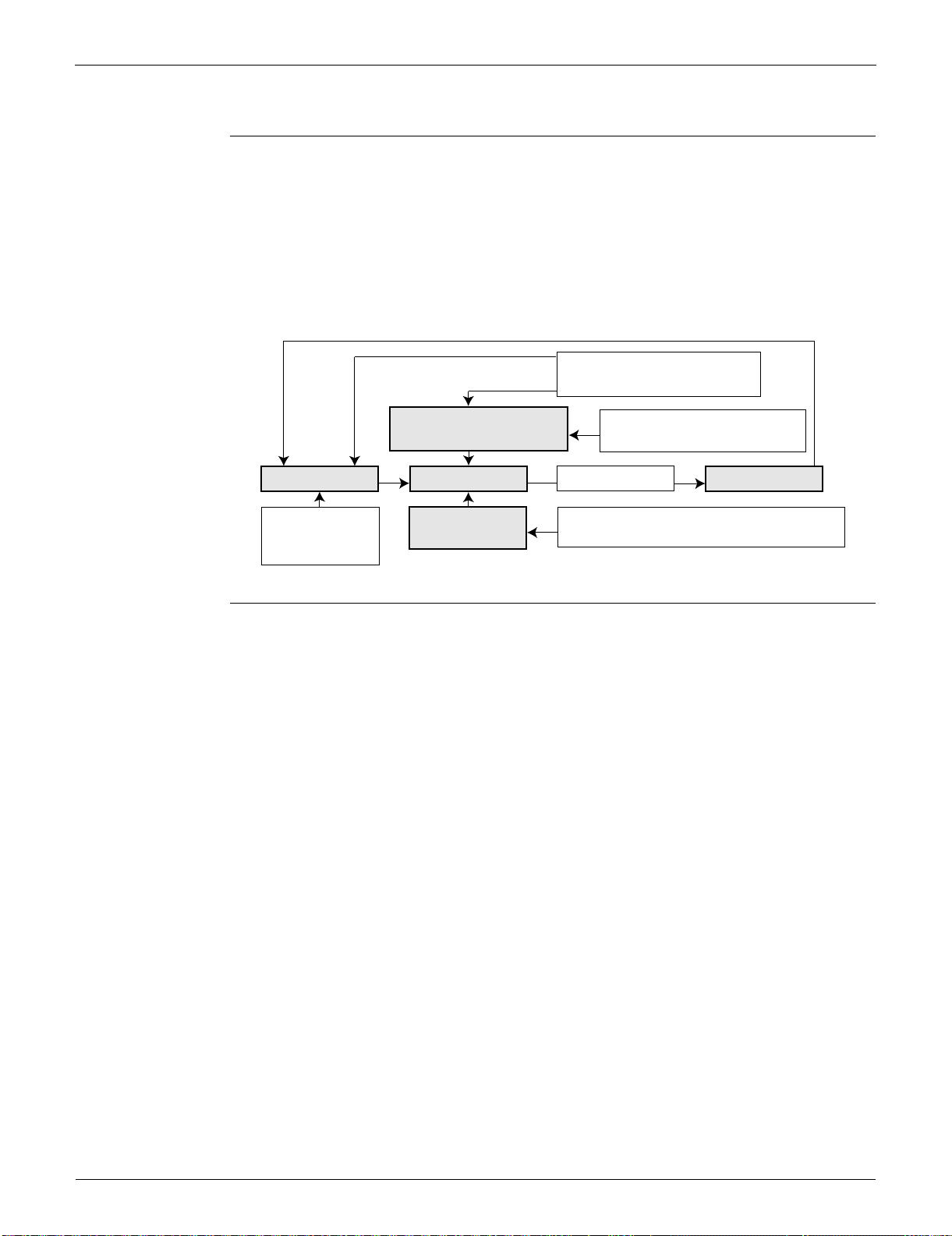
Control Specification SiUS091133
43 Function and Control
3.2 Frequency Control
Outline Frequency is determined according to the difference between the room thermistor temperature and
the target temperature.
The function is explained as follows.
1. How to determine frequency
2. Frequency command from the indoor unit (Difference between the room thermistor temperature
and the target temperature)
3. Frequency initial setting
4. PI control
Detail How to Determine Frequency
The compressor’s frequency is determined by taking the following steps.
For Cooling Only Model
1. Determine command frequency
Command frequency is determined in the following order of priority.
1. Forced cooling
2. Indoor frequency command
2. Determine upper limit frequency
The minimum value is set as an upper limit frequency among the frequency upper limits of the
following functions:
Compressor protection, input current, discharge pipe temperature, freeze-up protection.
3. Determine lower limit frequency
The maximum value is set as a lower limit frequency among the frequency lower limits of the
following function:
Pressure difference upkeep.
4. Determine prohibited frequency
There is a certain prohibited frequency such as a power supply frequency.
For Heat Pump Model
1. Determine command frequency
Command frequency is determined in the following order of priority.
1. Limiting defrost control time
2. Forced cooling
3. Indoor frequency command
Command frequency
Limit frequency
Skip control
Lower limit function
Four way valve operating compensation (∗), etc.
Initial frequency
PI control
Defrost control (∗)
Dropping function
Input current control, etc.
Upper limit function
Compressor protection function
Upper limit frequency
FMAX
Lower limit frequency
FMIN
Target frequency
(R14717)
When the shift of the frequency is less than zero (ΔF<0) by PI control,
the target frequency is used as the command frequency.
(∗): only for heat pump models
SiUS091133 Control Specification
Function and Control 44
2. Determine upper limit frequency
The minimum value is set as an upper limit frequency among the frequency upper limits of the
following functions:
Compressor protection, input current, discharge pipe temperature, heating peak-cut, freeze-up
protection, defrost.
3. Determine lower limit frequency
The maximum value is set as a lower limit frequency among the frequency lower limits of the
following functions:
Four-way valve operation compensation, draft prevention, pressure difference upkeep.
4. Determine prohibited frequency
There is a certain prohibited frequency such as a power supply frequency.
Indoor Frequency Command (D signal)
The difference between the room thermistor temperature and the target temperature is taken as the
“D signal” and is used for frequency command.
Th OFF = Thermostat OFF
Frequency Initial Setting
<Outline>
When starting the compressor, the frequency is initialized according to the D value and the Q
value of the indoor unit.
Q value: Indoor unit output determined from indoor unit volume, airflow rate and other factors.
PI Control (Determine Frequency Up / Down by D Signal)
1. P control
The D value is calculated in each sampling time (15 ~ 20 seconds), and the frequency is
adjusted according to its difference from the frequency previously calculated.
2. I control
If the operating frequency does not change for more than a certain fixed time, the frequency is
adjusted according to the D value.
When the D value is low, the frequency is lowered.
When the D value is high, the frequency is increased.
3. Frequency management when other controls are functioning
When frequency is dropping;
Frequency management is carried out only when the frequency drops.
For limiting lower limit
Frequency management is carried out only when the frequency rises.
4. Upper and lower limit of frequency by PI control
The frequency upper and lower limits are set according to the command of the indoor unit.
When the indoor or outdoor unit quiet operation command comes from the indoor unit, the upper
limit frequency is lower than the usual setting.
Temperature
difference
D
signal
Temperature
difference
D
signal
Temperature
difference
D
signal
Temperature
difference
D
signal
–2.0°C (–3.6°F) Th
OFF
0°C (0°F) 4 2.0°C (3.6°F) 8 4.0°C (7.2°F) C
–1.5°C (–2.7°F) 1 0.5°C (0.9°F) 5 2.5°C (4.5°F) 9 4.5°C (8.1°F) D
–1.0°C (–1.8°F) 2 1.0°C (1.8°F) 6 3.0°C (5.4°F) A 5.0°C (9°F) E
–0.5°C (–0.9°F) 3 1.5°C (2.7°F) 7 3.5°C (6.3°F) B 5.5°C (9.9°F) F
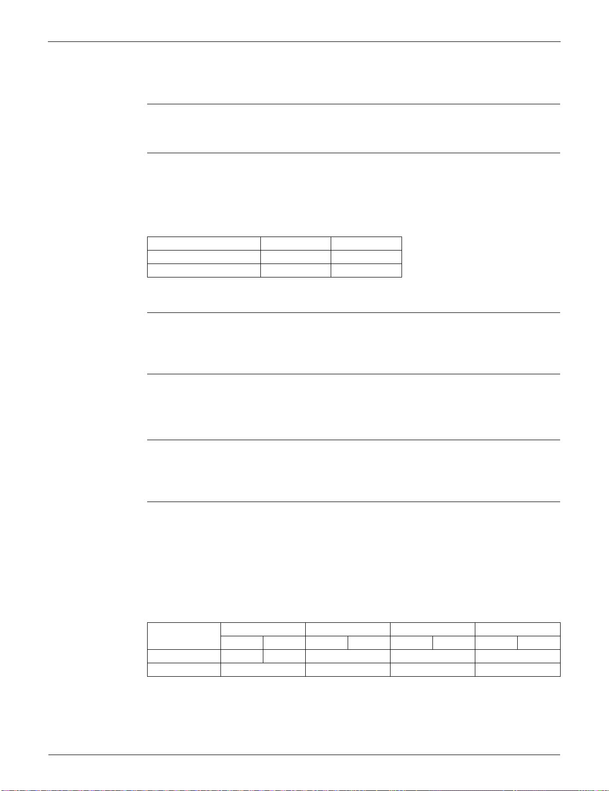
Control Specification SiUS091133
45 Function and Control
3.3 Controls at Mode Changing / Start-up
3.3.1 Preheating Operation
Outline The inverter operation in open phase starts with the conditions of the preheating command from the
indoor unit, the outdoor temperature, and the discharge pipe temperature.
Detail ON Condition
When the discharge pipe temperature is below A, the inverter operation in open phase starts.
OFF Condition
When the discharge pipe temperature is higher than B, the inverter operation in open phase
stops.
3.3.2 Four-Way Valve Switching
Outline In heating operation, current is conducted, and in cooling and defrosting operation, current is not
conducted. In order to eliminate the switching sound as the four-way valve coil switches from ON to
OFF when the heating is stopped, the OFF delay switch of the four-way valve is carried out.
Detail OFF delay switch of four-way valve:
The four-way valve coil is energized for 150 ~ 160 seconds after the operation is stopped.
3.3.3 Four-Way Valve Operation Compensation
Outline At the beginning of the operation as the four-way valve is switched, the pressure difference to
activate the four-way valve is acquired by having output frequency which is more than a certain
fixed frequency, for a certain fixed time.
Detail Starting Conditions
1. When starting the compressor for heating
2. When the operation mode changes from heating to cooling
3. When starting the compressor for defrosting
4. When starting the compressor for heating after defrosting
5. When starting the compressor for the first time after resetting with the power ON
6. When starting the compressor after the fault of switching over cooling / heating
The lower limit of frequency keeps A Hz for B seconds with any conditions 1 through 6 above.
3.3.4 3-minute Standby
Turning on the compressor is prohibited for 3 minutes after turning it off.
(Except when defrosting.)
AB
09/12 class 0°C (32°F) 12°C (53.6°F)
15/18/24/30/36 class 0°C (32°F) 8°C (46.4°F)
09/12 class 15/18 class 24 class 30/36 class
Cooling Heating Cooling Heating Cooling Heating Cooling Heating
A (Hz) 68 66 48 28 83
B (seconds) 45 70 70 70
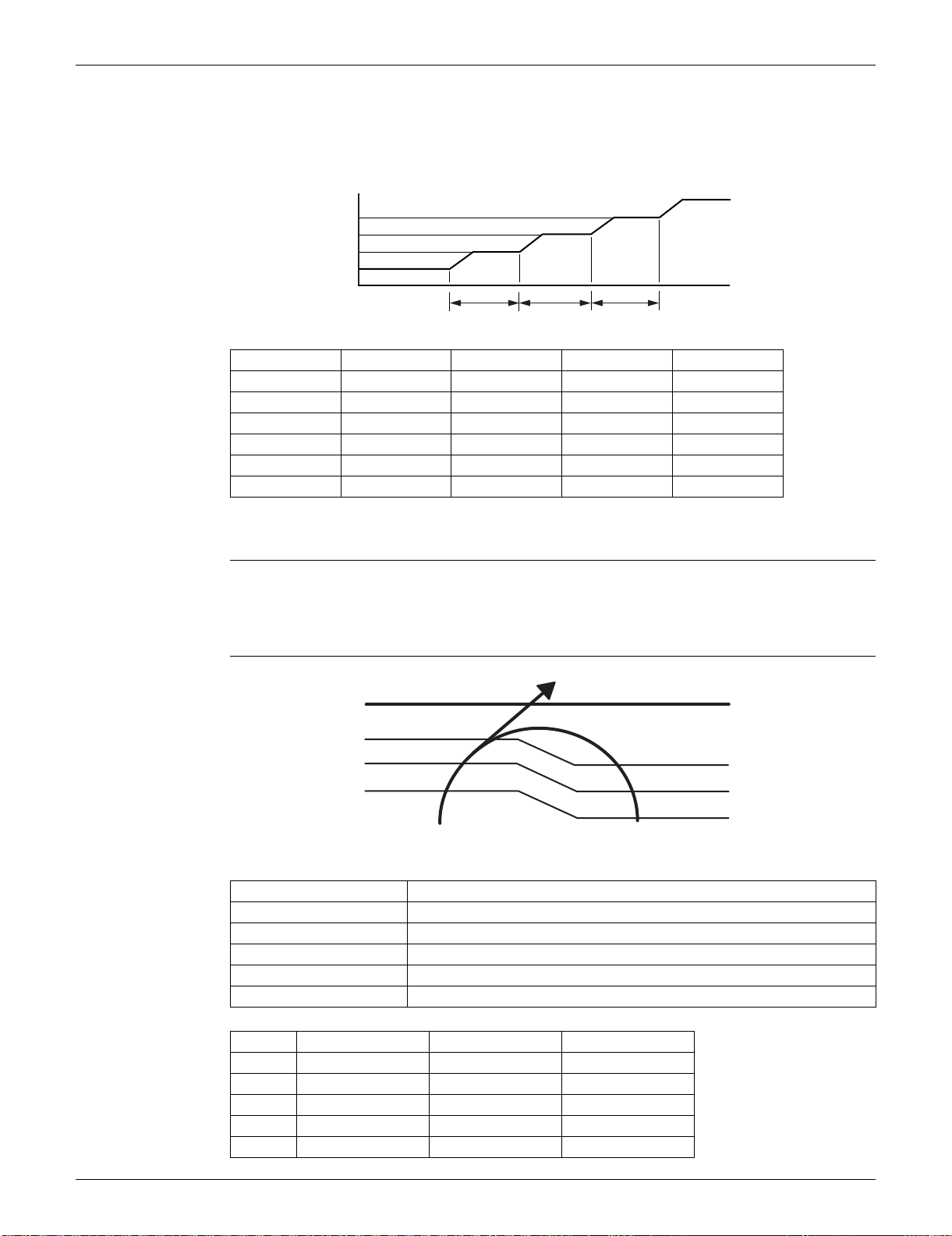
SiUS091133 Control Specification
Function and Control 46
3.3.5 Compressor Protection Function
When turning the compressor from OFF to ON, the upper limit of frequency is set as follows. (The
function is not activated when defrosting.)
3.4 Discharge Pipe Temperature Control
Outline The discharge pipe temperature is used as the internal temperature of the compressor. If the
discharge pipe temperature rises above a certain level, the upper limit of frequency is set to keep
the discharge pipe temperature from rising further.
Detail
09/12 class 15/18 class 24 class 30/36 class
A (Hz) 48 55 55 46 ~ 55
B (Hz) 64 70 65 65
C (Hz) 88 85 80 80
D (seconds) 240 120 120 120 ~ 500
E (seconds) 360 200 200 100 ~ 200
F (seconds) 180 470 470 470
(sec.)
Time
(R13528)
(Hz)
Frequency
C
B
DEF
A
Zone Control
Stop zone When the temperature reaches the stop zone, the compressor stops.
Dropping zone The upper limit of frequency decreases.
Keep zone The upper limit of frequency is kept.
Up zone The upper limit of frequency increases.
Reset zone The upper limit of frequency is canceled.
09/12 class 15/18 class 24/30/36 class
A 110°C (230°F) 110°C (230°F) 120°C (248°F)
B 105°C (221°F) 103°C (217.4°F) 111°C (231.8°F)
C 101°C (213.8°F) 101.5°C (214.7°F) 109°C (228.2°F)
D 99°C (210.2°F) 100°C (212°F) 107°C (224.6°F)
E 97°C (206.6°F) 95°C (203°F) 107°C (224.6°F)
(R14711)
Discharge pipe
temperature
Stop zone
Dropping zone
Keep zone
Up zone
Reset zone
E
A
B
C
D
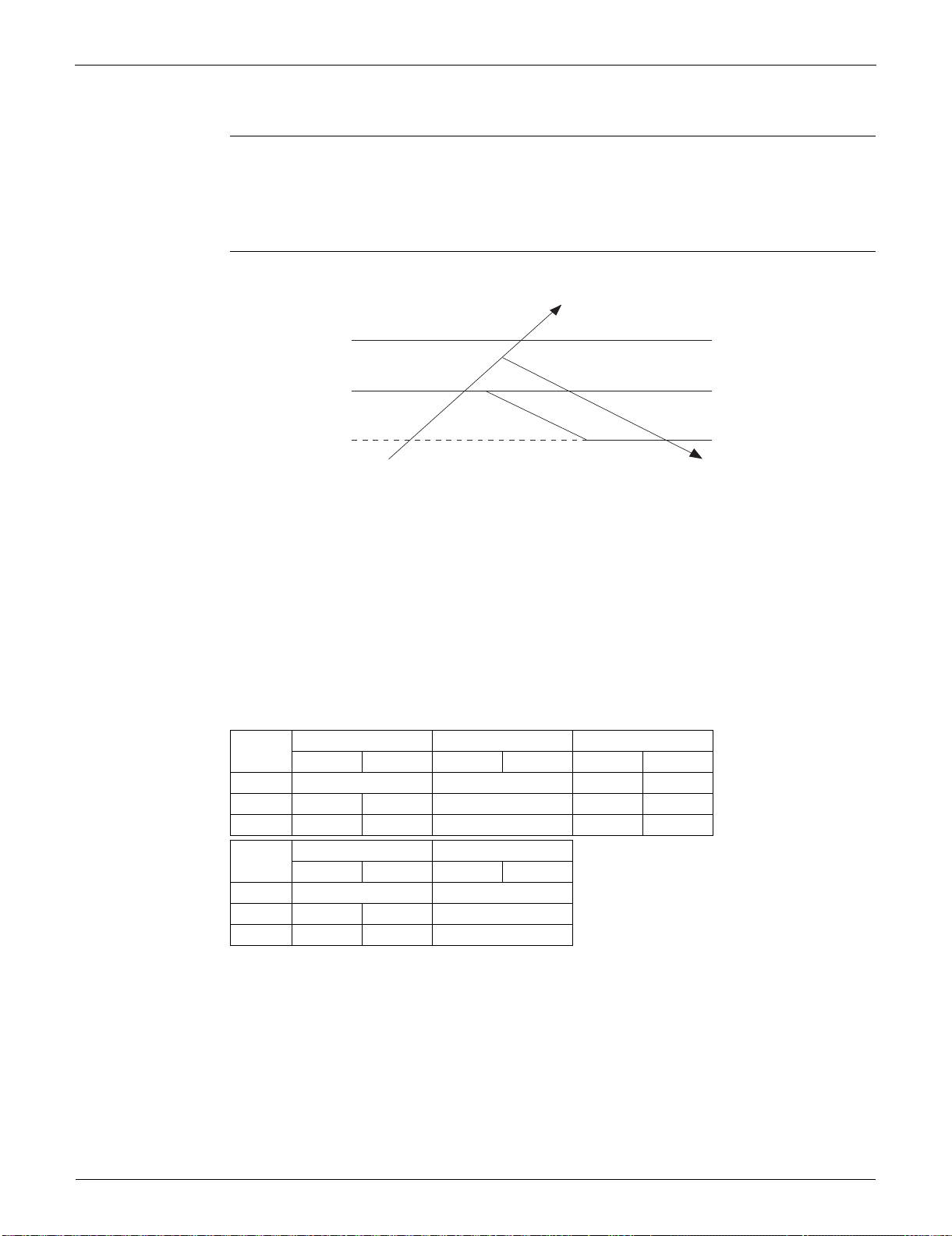
Control Specification SiUS091133
47 Function and Control
3.5 Input Current Control
Outline The microcomputer calculates the input current while the compressor is running, and sets the
frequency upper limit from the input current.
In case of heat pump models, this control which is the upper limit control of the frequency takes
priority over the lower limit of control of four-way valve operation compensation.
Detail
Frequency control in each zone
Stop zone
After 2.5 seconds in this zone, the compressor is stopped.
Dropping zone
The upper limit of the compressor frequency is defined as operation frequency – 2 Hz.
After this, the output frequency is lowered by 2 Hz every second until it reaches the keep zone.
Keep zone
The present maximum frequency goes on.
Reset zone
Limit of the frequency is canceled.
Limitation of current dropping and stop value according to the outdoor temperature
The current drops when outdoor temperature becomes higher than a certain level (depending
on the model).
09 class 12 class 15/18 class
Cooling Heating Cooling Heating Cooling Heating
A (A) 9.25 9.25 15.0 15.25
B (A) 6.25 7.5 8.25 13.0 13.25
C(A) 5.5 6.75 7.5 12.0 12.25
24 class 30/36 class
Cooling Heating Cooling Heating
A (A) 20.0 20.0
B (A) 15.0 17.0 19.0
C(A) 14.0 16.0 18.0
Compressor Stop
Input current
Dropping Zone
Stop Zone
Keep Zone
Reset Zone
(R14643)
A
(A)
B
C
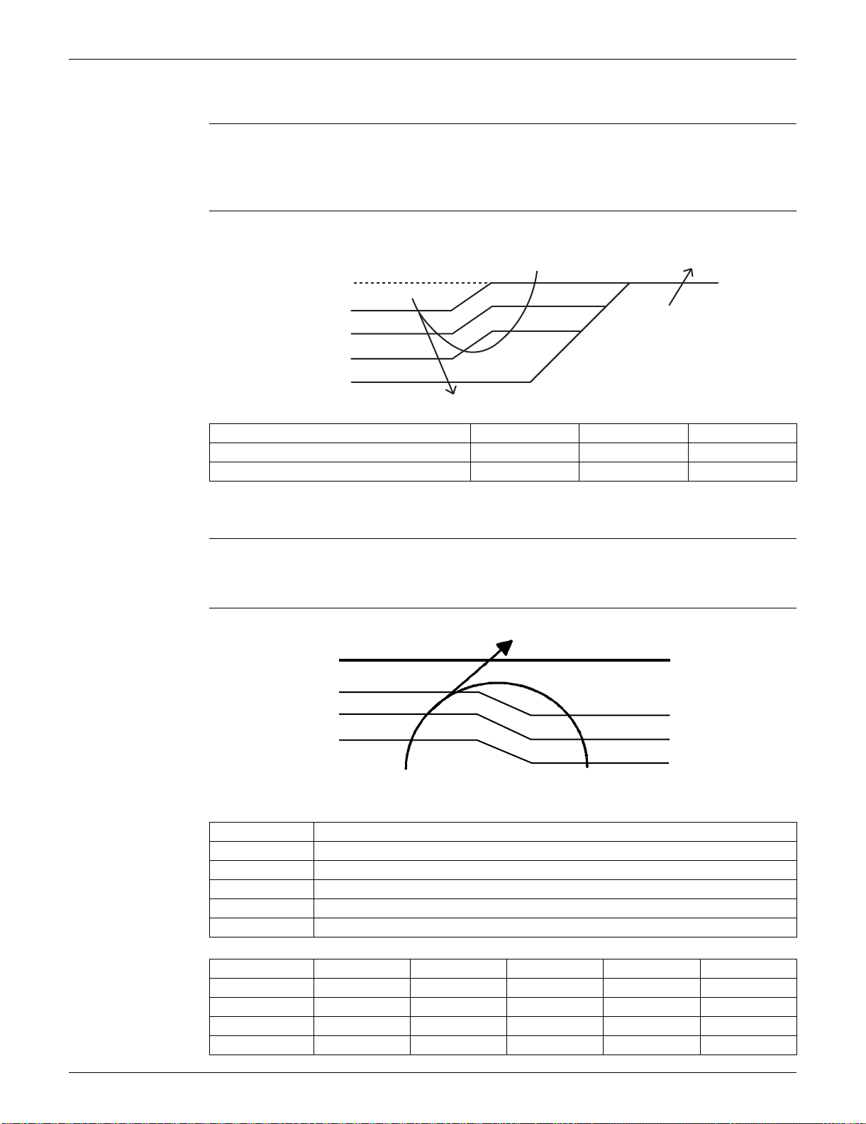
SiUS091133 Control Specification
Function and Control 48
3.6 Freeze-up Protection Control
Outline During cooling operation, the signal sent from the indoor unit controls the operating frequency
limitation and prevents freezing of the indoor heat exchanger. (The signal from the indoor unit is
divided into zones.)
Detail The operating frequency limitation is judged with the indoor heat exchanger temperature.
3.7 Heating Peak-cut Control
Outline During heating operation, the indoor heat exchanger temperature determines the frequency upper
limit to prevent abnormal high pressure.
Detail
ABC
FTXS09/12LVJU 9.5°C (49.1°F) 7.5°C (45.5°F) 5.5°C (41.9°F)
FTXS15/18/24/30/36LVJU, FDXS series 7°C (44.6°F) 5°C (41°F) 3°C (37.4°F)
(R16967)
Reset zone
Indoor heat exchanger
thermistor temperature
Up zone
Keep zone
Dropping zone
Stop zone
0˚C
(32˚F)
C
B
A
13˚C
(55.4˚F)
Zone Control
Stop zone When the temperature reaches the stop zone, the compressor stops.
Dropping zone The upper limit of frequency decreases.
Keep zone The upper limit of frequency is kept.
Up zone The upper limit of frequency increases.
Reset zone The upper limit of frequency is canceled.
ABCDE
09 class 60°C (140°F) 56°C (132.8°F) 53°C (127.4°F) 51°C (123.8°F) 46°C (114.8°F)
12 class 60°C (140°F) 52°C (125.6°F) 50°C (122°F) 48°C (118.4°F) 43°C (109.4°F)
15/18 class 60°C (140°F) 57°C (134.6°F) 56°C (132.8°F) 54°C (129.2°F) 52°C (125.6°F)
24/30/36 class 65°C (149°F) 56°C (132.8°F) 55°C (131°F) 53°C (127.4°F) 51°C (123.8°F)
Indoor heat exchanger
thermistor temperature
Stop zone
Dropping zone
Keep zone
Up zone
Reset zone
(R14665)
D
C
B
A
E

Control Specification SiUS091133
49 Function and Control
3.8 Outdoor Fan Control
1. Fan ON control to cool down the electrical box
The outdoor fan is turned ON when the electrical box temperature is high while the compressor is
OFF.
2. Fan OFF control during defrosting
The outdoor fan is turned OFF during defrosting.
3. Fan OFF delay when stopped
The outdoor fan is turned OFF 60 seconds after the compressor stops.
4. Fan speed control for pressure difference upkeep
The rotation speed of the outdoor fan is controlled for keeping the pressure difference during
cooling operation with low outdoor temperature.
When the pressure difference is low, the rotation speed of the outdoor fan is reduced.
When the pressure difference is high, the rotation speed of the outdoor fan is controlled as well
as normal operation.
5. Fan speed control during forced cooling operation
The outdoor fan is controlled as well as normal operation during forced cooling operation.
6. Fan speed control during POWERFUL operation
The rotation speed of the outdoor fan is increased during POWERFUL operation.
7. Fan speed control during indoor / outdoor unit quiet operation
The rotation speed of the outdoor fan is reduced by the command of the indoor / outdoor unit quiet
operation.
8. Fan ON/OFF control when operation starts / stops
The outdoor fan is turned ON when the operation starts. The outdoor fan is turned OFF when the
operation stops.
3.9 Liquid Compression Protection Function
Outline In order to obtain the dependability of the compressor, the compressor is stopped according to the
outdoor temperature and temperature of the outdoor heat exchanger.
Detail Operation stops depending on the outdoor temperature.
Compressor turns off under the conditions that the system is in cooling operation and outdoor
temperature is below 0°C (32°F).
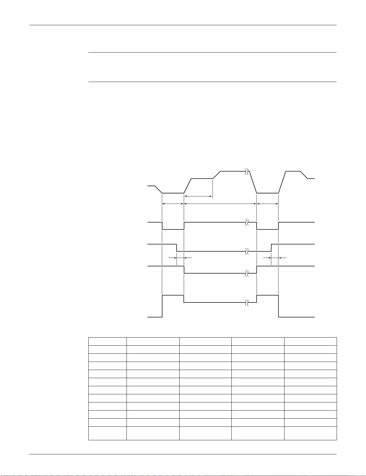
SiUS091133 Control Specification
Function and Control 50
3.10 Defrost Control
Outline Defrosting is carried out by the cooling cycle (reverse cycle). The defrosting time or outdoor heat
exchanger temperature must be more than a certain value to finish.
Detail Conditions for Starting Defrost
The starting conditions are determined with the outdoor temperature and the outdoor heat
exchanger temperature.
The system is in heating operation.
The compressor operates for 6 minutes.
More than A minutes (depending on the duration of the previous defrost control) of accumulated
time have passed since the start of the operation, or ending the previous defrosting.
Conditions for Canceling Defrost
The judgment is made with the outdoor heat exchanger temperature L.
09/12 class 15/18 class 24 class 30/36 class
A (minutes) 15 ~ 28 15 ~ 44 15 ~ 38 15 ~ 38
B (Hz) 76 55 39 39
C (Hz) 86 90 62 62
D (seconds) 50 60 60 60
E (seconds) 60 120 120 120
F (seconds) 480 340 530 530
G (seconds) 60 50 60 60
H (pulse) 450 450 450 450
J (pulse) 350 450 300 350
K (pulse) 450 450 400 400
L
4 ~ 18°C
(39.2 ~ 64.4°F)
4 ~ 12°C
(39.2 ~ 53.6°F)
4 ~ 12°C
(39.2 ~ 53.6°F)
4 ~ 18°C
(39.2 ~ 64.4°F)
Frequency
Compressor
Four way valve
Fan
ON
OFF
ON
OFF
ON
OFF
0 Hz
B Hz
C Hz
5 sec.
J pulse
K pulseH pulse
Initial opening
PI control
5 sec.
G sec.
(R16577)
Electronic expansion
valve opening
D sec.
E sec.
F sec.
Control Specification SiUS091133
51 Function and Control
3.11 Electronic Expansion Valve Control
Outline The following items are included in the electronic expansion valve control.
Electronic expansion valve is fully closed
1. Electronic expansion valve is fully closed when turning on the power.
2. Pressure equalizing control
Open Control
1. Electronic expansion valve control when starting operation
2. Electronic expansion valve control when the frequency changes
3. Electronic expansion valve control for defrosting
4. Electronic expansion valve control when the discharge pipe temperature is abnormally high
5. Electronic expansion valve control when the discharge pipe thermistor is disconnected
Feedback Control
1. Target discharge pipe temperature control
Detail The followings are the examples of electronic expansion valve control which function in each
operation mode.
Cooling
−
h
−−−−−−
−−
h
−
h
−−−
−−−
h
−−−−
−−−−−
hh
−
−
hhhh
hhhhh
−−−
h
−−−−−−−
−
h
−
Heating
−
h
−−−−−−
−−
h
−
h
−−−
−−−
h
−−−−
−−−−−
hh
−
−
hhhh
−−−
−−−−−−−
h
h
−−−−−−−
−
hhhhhh
−
h : Holding Functions
— : No Functions
Starting control
Control when the frequency changes
Target discharge pipe temperature control
Control for disconnection of the discharge
pipe thermistor
High discharge pipe temperature control
Pressure equalizing control
Opening limit control
Starting control
Control when the frequency changes
Target discharge pipe temperature control
Control for disconnection of the discharge
pipe thermistor
High discharge pipe temperature control
Defrost control
Pressure equalizing control
Opening limit control
When the power turns on or when the
compressor stops
When the operation starts
When the frequency changes under
starting control
During target discharge pipe
temperature control
When the frequency changes under
target discharge pipe temperature control
When the disconnection of the discharge
pipe thermistor is ascertained
When the frequency changes under the control for
disconnection of the discharge pipe thermistor
Under defrost control
SiUS091133 Control Specification
Function and Control 52
3.11.1 Fully Closing with Power ON
The electronic expansion valve is initialized when turning on the power. The opening position is set
and the pressure equalization is developed.
3.11.2 Pressure Equalizing Control
When the compressor is stopped, the pressure equalization control is activated. The electronic
expansion valve opens, and develops the pressure equalization.
3.11.3 Opening Limit Control
Outline A maximum and minimum opening of the electronic expansion valve are limited.
Detail
The electronic expansion valve is fully closed when cooling operation stops, and is opened at a
fixed degree during defrosting.
3.11.4 Starting Operation Control
The electronic expansion valve opening is controlled when the operation starts, and prevents
superheating or liquid compression.
3.11.5 Control when the Frequency Changes
When the target discharge pipe temperature control is active, if the target frequency is changed to a
specified value in a certain time period, the target discharge pipe temperature control is canceled
and the target opening of the electronic expansion valve is changed according to the shift.
3.11.6 High Discharge Pipe Temperature Control
When the compressor is operating, if the discharge pipe temperature exceeds a certain value, the
electronic expansion valve opens and the refrigerant runs to the low pressure side. This procedure
lowers the discharge pipe temperature.
09/12 class 15/18 class 24 class 30/36 class
Maximum opening (pulse) 480 480 450 480
Minimum opening (pulse) 52 54 75 10
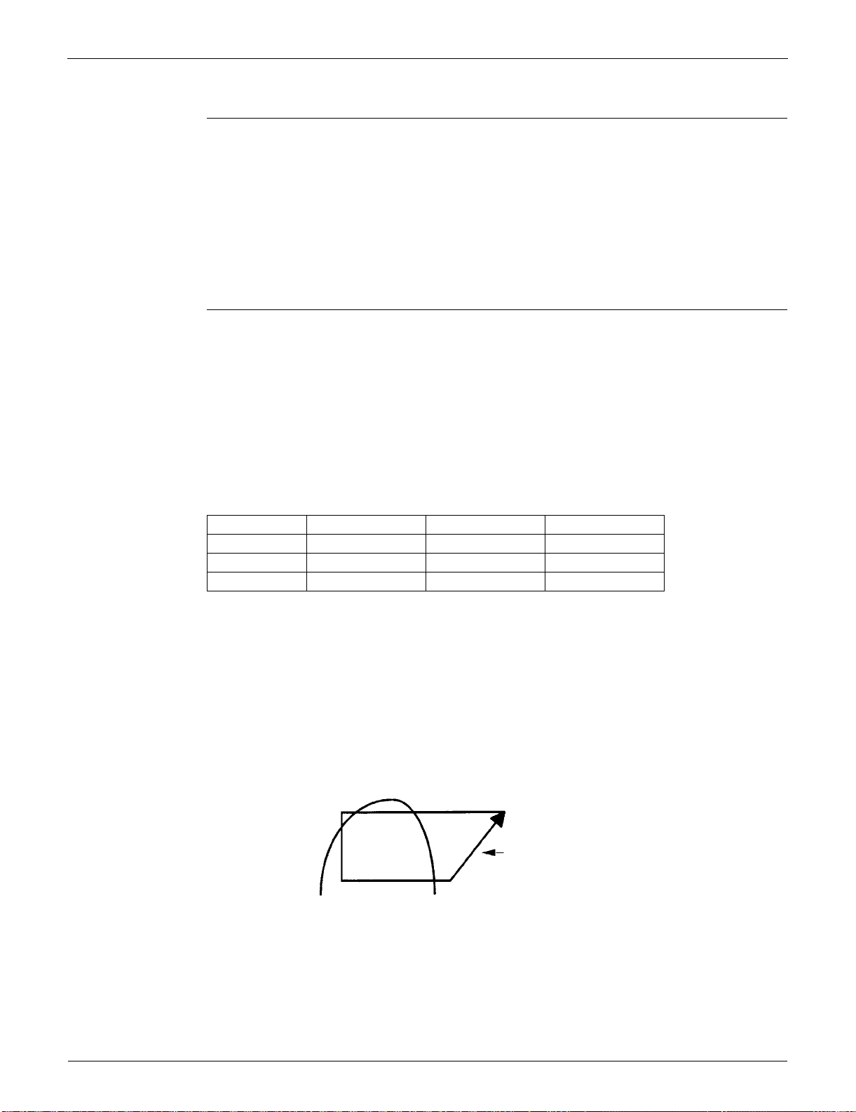
Control Specification SiUS091133
53 Function and Control
3.11.7 Control for Disconnection of the Discharge Pipe Thermistor
Outline The disconnection of the discharge pipe thermistor is detected by comparing the discharge pipe
temperature with the condensation temperature. If the discharge pipe thermistor is disconnected,
the electronic expansion valve opens according to the outdoor temperature and the operation
frequency, operates for a specified time, and then stops.
After 3 minutes, the operation restarts and checks if the discharge pipe thermistor is disconnected.
If the discharge pipe thermistor is disconnected, the system stops after operating for a specified
time.
If the disconnection is detected repeatedly, the system is shut down. When the compressor runs for
60 minutes without any error, the error counter is reset.
Detail When the starting control (cooling: A seconds, heating: B seconds) finishes, the detection timer for
disconnection of the discharge pipe thermistor (
C seconds) starts. When the timer is over, the
following adjustment is made.
1. When the operation mode is cooling
When the following condition is fulfilled, the discharge pipe thermistor disconnection is
ascertained.
Discharge pipe temperature + 6°C (+ 10.8°F) < outdoor heat exchanger temperature
2. When the operation mode is heating
When the following condition is fulfilled, the discharge pipe thermistor disconnection is
ascertained.
Discharge pipe temperature + 6°C (+ 10.8°F) < indoor heat exchanger temperature
Adjustment when the thermistor is disconnected
When the disconnection is ascertained, the compressor continues operation for 9 minutes and then
stops.
If the compressor stops repeatedly, the system is shut down.
3.11.8 Target Discharge Pipe Temperature Control
The target discharge pipe temperature is obtained from the indoor and outdoor heat exchanger
temperature, and the electronic expansion valve opening is adjusted so that the actual discharge
pipe temperature becomes close to the target discharge pipe temperature. (Indirect SH
(superheating) control using the discharge pipe temperature)
The electronic expansion valve opening and the target discharge pipe temperature are adjusted
every 20 seconds. The target discharge pipe temperature is controlled by indoor heat exchanger
temperature and outdoor heat exchanger temperature. The opening degree of the electronic
expansion valve is controlled by the followings.
Target discharge pipe temperature
Actual discharge pipe temperature
Previous discharge pipe temperature
09/12 class 15/18/24 class 30/36 class
A (seconds) 10 10 30
B (seconds) 120 30 30
C (seconds) 810 540 540
SC
(Subcool)
SH
(Superheat)
The target discharge pipe
temperature is set as to become the
aiming SH.
The inclination does not change
depending on the operating condition.
(R14213)
SiUS091133 Control Specification
Function and Control 54
3.12 Malfunctions
3.12.1 Sensor Malfunction Detection
Sensor malfunction may occur in the thermistor.
Relating to Thermistor Malfunction
1. Outdoor heat exchanger thermistor
2. Discharge pipe thermistor
3. Radiation fin thermistor
4. Outdoor temperature thermistor
3.12.2 Detection of Overcurrent and Overload
Outline An excessive output current is detected and the OL temperature is observed to protect the
compressor.
Detail If the OL (compressor head) temperature exceeds 120 ~ 130°C (248 ~ 266°F), the system
shuts down the compressor.
If the inverter current exceeds 9.25 ~ 20 A (depending on the model), the system shuts down
the compressor.
3.12.3 Refrigerant Shortage Control
Outline I: Detecting by power consumption
If the power consumption is below the specified value and the frequency is higher than the
specified frequency, it is regarded as refrigerant shortage.
The power consumption is low comparing with that in the normal operation when refrigerant is
insufficient, and refrigerant shortage is detected by checking power consumption.
II: Detecting by discharge pipe temperature
If the discharge pipe temperature is higher than the target discharge pipe temperature, and the
electronic expansion valve is fully open for more than the specified time, it is regarded as
refrigerant shortage.
III: Detecting by the difference of temperature
If the difference between suction and discharge temperature is smaller than the specified value, it is
regarded as refrigerant shortage.
Refer to page 104 for detail.
Frequency
Power consumption
Refrigerant shortage zone
(R12434)
40 ~ 55 Hz
(depending on
the model)
(R1391)
Target discharge
pipe temperature
Refrigerant shortage
zone

SiUS091133
55 Operation Manual
Part 5
Operation Manual
1. System Configuration................................................................................56
2. FTXS Series..............................................................................................57
2.1 Remote Controller......................................................................................57
2.2 AUTO · DRY · COOL · HEAT · FAN Operation..........................................59
2.3 Adjusting the Airflow Direction and Rate....................................................61
2.4 COMFORT AIRFLOW / INTELLIGENT EYE Operation............................. 64
2.5 POWERFUL Operation..............................................................................66
2.6 OUTDOOR UNIT QUIET Operation...........................................................67
2.7 ECONO Operation .....................................................................................68
2.8 OFF TIMER Operation...............................................................................69
2.9 ON TIMER Operation.................................................................................70
2.10 WEEKLY TIMER Operation ....................................................................... 71
3. FDXS Series .............................................................................................77
3.1 Remote Controller......................................................................................77
3.2 AUTO · DRY · COOL · HEAT · FAN Operation..........................................79
3.3 Adjusting the Airflow Rate..........................................................................81
3.4 POWERFUL Operation..............................................................................82
3.5 OUTDOOR UNIT QUIET Operation...........................................................83
3.6 ECONO Operation .....................................................................................84
3.7 OFF TIMER Operation...............................................................................85
3.8 ON TIMER Operation.................................................................................86

SiUS091133 System Configuration
Operation Manual 56
1. System Configuration
After installation and trial operation of the room air conditioner are completed, the air conditioner
should be handled and operated as described in the following pages. Every user should be
informed on the correct method of operation and how to check if it can cool (or heat) well, and how
to use it efficiently.
Providing instructions to the user can reduce requests for servicing by 80%. However proficient the
installation and operating functions of the AC system are, the customer may fault either the room
air conditioner or its installation work when it is actually due to improper handling. The installation
work and the handing-over of the unit can only be considered completed when its handling has
been fully explained to the user without using technical terms, and while imparting full knowledge of
the equipment.

FTXS Series SiUS091133
57 Operation Manual
2. FTXS Series
2.1 Remote Controller
Names of Parts
Remote Controller
Signal transmitter
FAN setting button
POWERFUL button
Display (LCD)
TEMPERATURE
adjustment buttons
ON/OFF button
Front cover
Receiver
• To use the remote controller, aim the
transmitter at the indoor unit. If there
is anything to block signals between
the unit and the remote controller,
such as a curtain, the unit will not
operate.
• Do not drop the remote controller. Do
not get it wet.
• The maximum distance for
communication is approximately 23ft
(7m).
• Selects the airflow rate setting.
• POWERFUL operation.
• Displays the current settings.
(In this illustration, each section is
shown with all its displays on for the
purpose of explanation.)
• Changes the temperature setting.
• Press this button once to start
operation.
Press once again to stop it.
• Open the front cover.
<ARC452A21>
Page 14
Page 17
Page 12
Page 11
Page 8
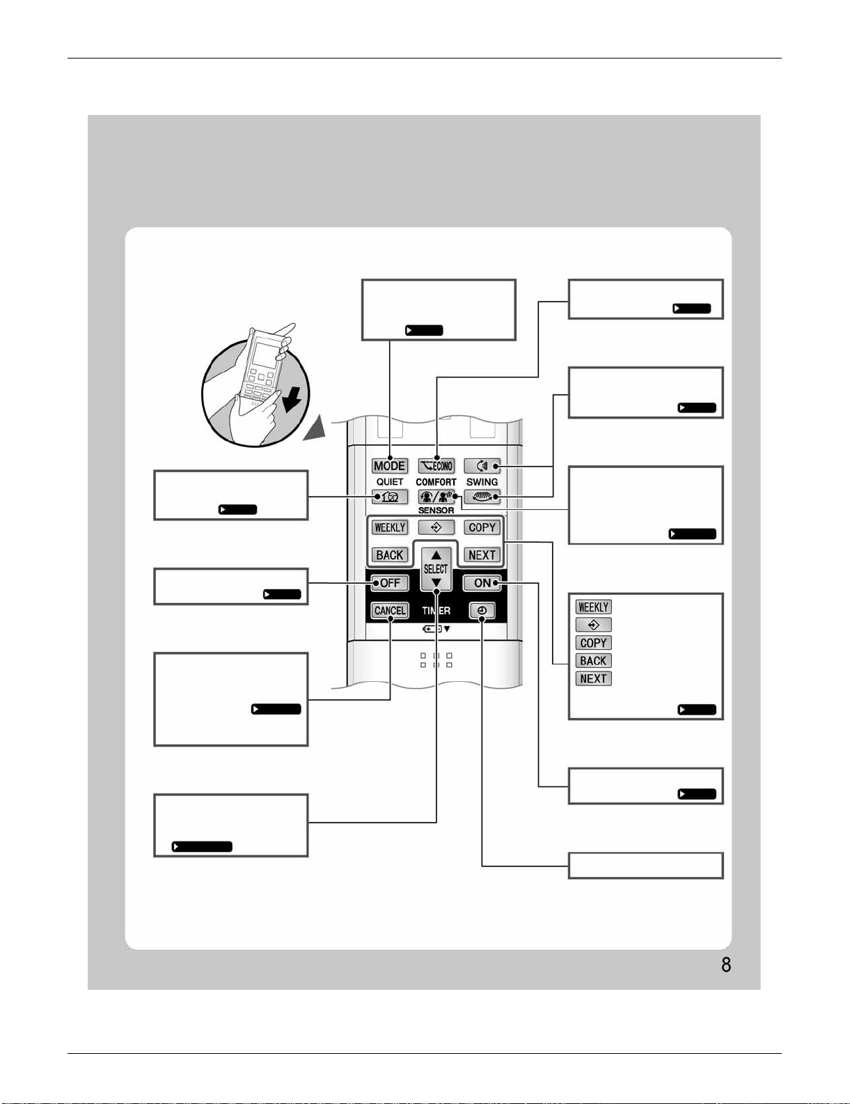
SiUS091133 FTXS Series
Operation Manual 58
Open the front cover
QUIET button
OFF TIMER button
TIMER CANCEL
button
SELECT button
MODE selector button ECONO button
SWING button
COMFORT/SENSOR
button
ON TIMER button
CLOCK button
Page 18
Page 20
Page 20,21
Page 20,21,22
Page 21
Page 22
Page 15,16
Page 13
Page 19
• OUTDOOR UNIT QUIET
operation.
• Cancels the timer setting.
• It cannot be used for the
WEEKLY TIMER operation.
• Changes the ON/OFF TIMER
and WEEKLY TIMER settings.
Page 11
• Selects the operation mode.
(AUTO/DRY/COOL/HEAT/
FAN)
• ECONO operation.
• Adjusting the airflow direction.
• COMFORT AIRFLOW and
INTELLIGENT EYE operation.
• WEEKLY TIMER operation.
: WEEKLY button
: PROGRAM button
: COPY button
: BACK button
: NEXT button
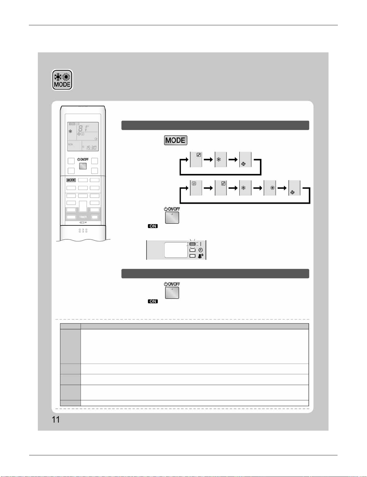
FTXS Series SiUS091133
59 Operation Manual
2.2 AUTO · DRY · COOL · HEAT · FAN Operation
AUTO · DRY · COOL · HEAT ·
FAN Operation
The air conditioner operates with the operation mode of your choice.
From the next time on, the air conditioner will operate with the same operation mode.
To start operation
To stop operation
1.
Press and select an operation mode.
2.
Press .
Press again.
• Each pressing of the button advances the mode setting in sequence.
• “ ” is displayed on the LCD.
• The OPERATION lamp lights green.
• “ ” is no longer displayed on the LCD.
• The OPERATION lamp goes off.
Display
NOTE
MODE
HEAT
COOL
DRY
AUTO
FAN
Notes on each operation mode
• Since this air conditioner heats the room by taking heat from outdoor air to indoors, the heating capacity becomes smaller in lower outdoor
temperatures. If the heating effect is insufficient, it is recommended to use another heating appliance in combination with the air conditioner.
• The heat pump system heats the room by circulating hot air around all parts of the room. After the start of HEAT operation, it takes some
time before the room gets warmer.
• In HEAT operation, frost may occur on the outdoor unit and lower the heating capacity. In that case, the system switches into defrosting
operation to take away the frost.
• During defrosting operation, hot air does not flow out of indoor unit.
• This air conditioner cools the room by releasing the heat in the room outside. Therefore, the cooling performance of the air conditioner may
be degraded if the outdoor temperature is high.
• The computer chip works to rid the room of humidity while maintaining the temperature as much as possible. It automatically controls
temperature and airflow rate, so manual adjustment of these functions is unavailable.
• In AUTO operation, the system selects an appropriate operation mode (COOL or HEAT) based on the room and outside temperatures and
starts the operation.
• The system automatically reselects setting at a regular interval to bring the room temperature to user-setting level.
• This mode is valid for fan only.
COOLING ONLY
model
HEAT PUMP
model
DRY
AUTO DRY COOL HEAT FAN
COOL FAN
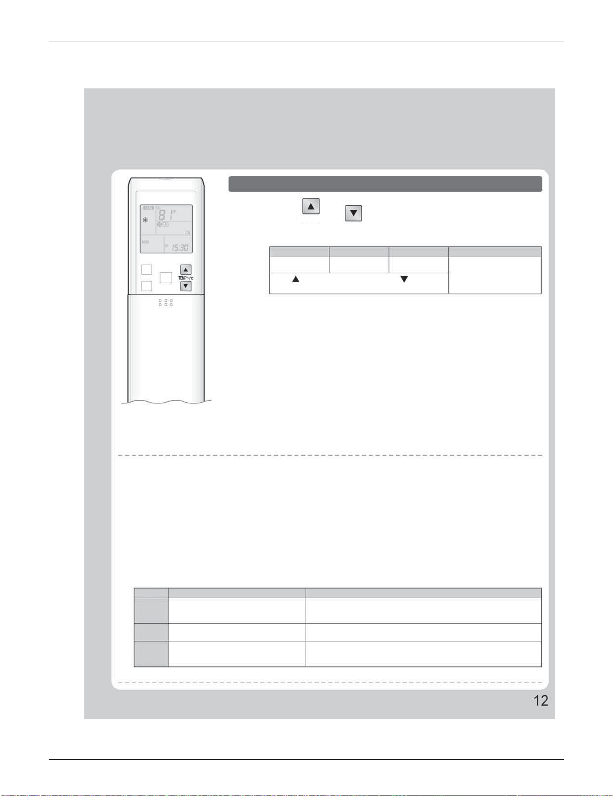
SiUS091133 FTXS Series
Operation Manual 60
To change the temperature setting
Press or .
• The displayed items on the LCD will change whenever either one of the buttons is
pressed.
COOL operation
HEAT operation
AUTO operation DRY or FAN operation
64-90°F
(18-32°C)
50-86°F
(10-30°C)
64-86°F
(18-30°C)
The temperature setting is
not variable.
Press to raise the temperature and press to lower the
temperature.
Operating conditions
Recommended temperature setting
• For cooling: 78-82°F (26-28°C)
• For heating: 68-75°F (20-24°C)
Tips for saving energy
• Be careful not to cool (heat) the room too much.
Keeping the temperature setting at a moderate level helps save energy.
• Cover windows with a blind or a curtain.
Blocking sunlight and air from outdoors increases the cooling (heating) effect.
• Clogged air filters cause inefficient operation and waste energy. Clean them once in about every 2 weeks.
Notes on the operating conditions
• The air conditioner always consumes a small amount of electricity even while it is not operating.
• If you are not going to use the air conditioner for a long period, for example in spring or autumn, turn the breaker off.
• Use the air conditioner in the following conditions.
MODE
COOL
HEAT
DRY
Operating conditions
If operation is continued out of this range
Outdoor temperature : 14-115°F (10-46°C)
Indoor temperature : 64-90°F (18-32°C)
Indoor humidity : 80% max.
Outdoor temperature : 5-75°F (–15-24°C)
Indoor temperature : 50-86°F (10-30°C)
Outdoor temperature : 14-115°F (10-46°C)
Indoor temperature : 64-90°F (18-32°C)
Indoor humidity : 80% max.
• A safety device may work to stop the operation.
• Condensation may occur on the indoor unit and drip.
• A safety device may work to stop the operation.
• A safety device may work to stop the operation.
• Condensation may occur on the indoor unit and drip.
• Operation outside this humidity or temperature range may cause a safety device to disable the system.
TEMP°F/°C
TEMP°F/°C
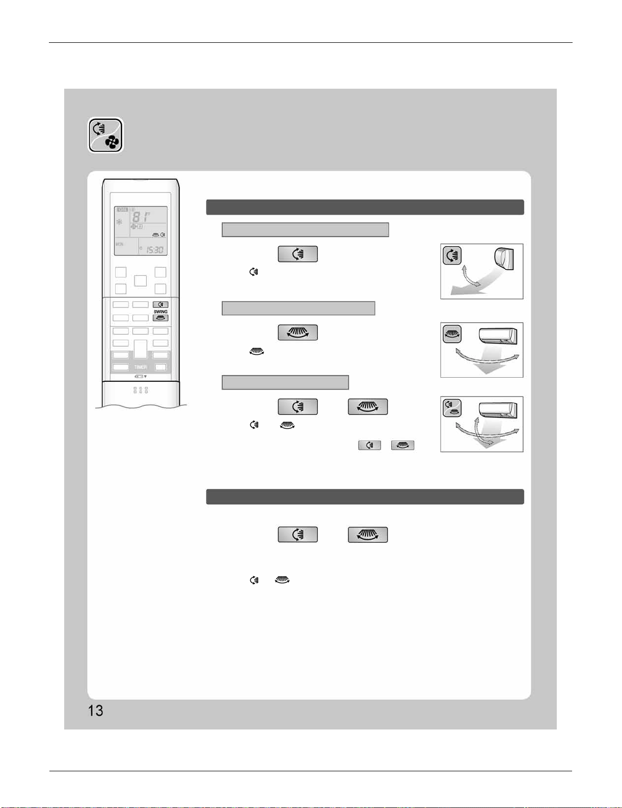
FTXS Series SiUS091133
61 Operation Manual
2.3 Adjusting the Airflow Direction and Rate
Adjusting the Airflow Direction
and Rate
You can adjust the airflow direction to increase your comfort.
To start auto swing
Upper and lower airflow direction
Right and left airflow direction
The 3-D airflow direction
Press .
Press .
Press and .
Press and when the louvers or
fins have reached the desired position.
• “ ” is displayed on the LCD.
• The louvers (horizontal blades) will begin to swing.
• “ ” is displayed on the LCD.
• The fins (vertical blades) will begin to swing.
• “ ” and “ ” are displayed on the LCD.
• The louvers and fins move in turn.
• To cancel 3-D airflow, press either or again.
The louvers or fins will stop moving.
• In the 3-D airflow, the louvers and fins move in turn.
• “ ” or “ ” is no longer displayed on the LCD.
To set the louvers or fins at desired position
• This function is effective while louvers or fins are in auto swing mode.
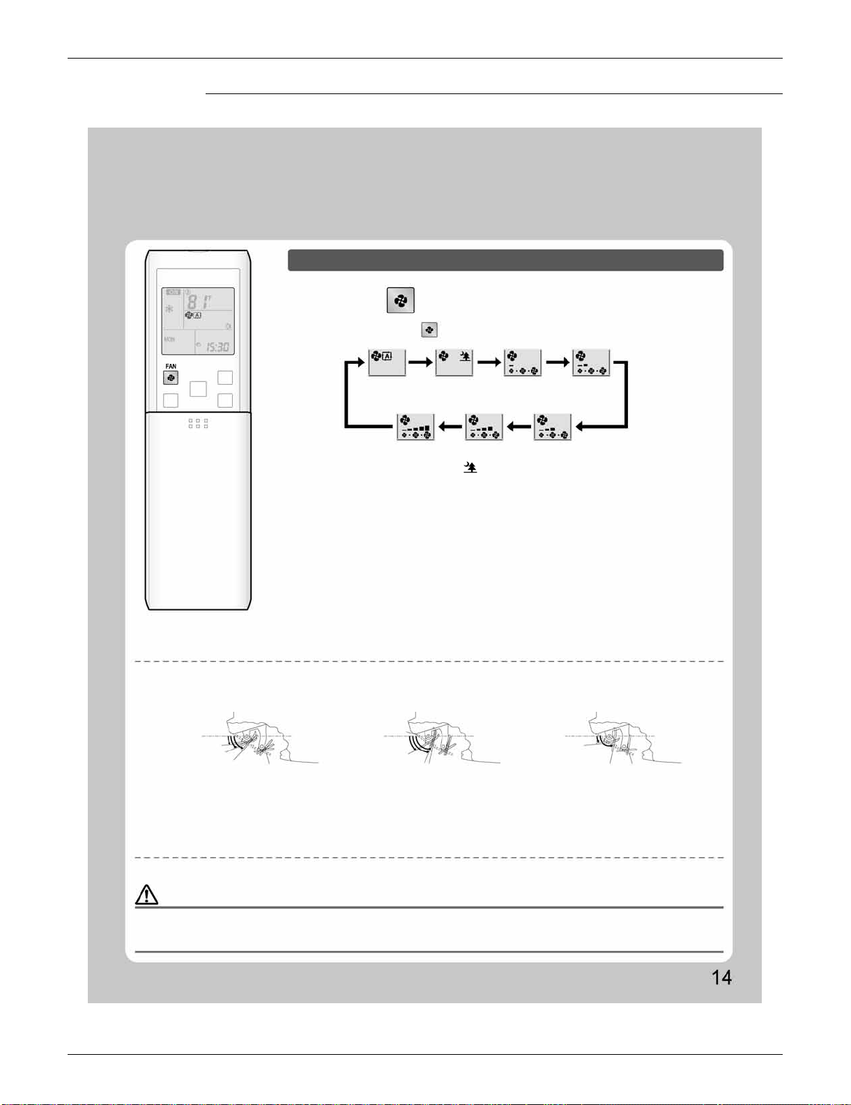
SiUS091133 FTXS Series
Operation Manual 62
FTXS09/12LVJU
Notes on the angles of the louvers
• The louvers swinging range depends on the operation. (See the figure.)
Note on 3-D airflow
• Using 3-D airflow circulates cold air, which tends to collected at the bottom of the room, and hot air, which tends to collect near the ceiling,
throughout the room, preventing areas of cold and hot developing.
Note on airflow rate setting
• At smaller airflow rates, the cooling (heating) effect is also smaller.
To adjust the airflow rate setting
Press .
• Each pressing of advances the airflow rate setting in sequence.
Auto
Indoor unit quiet
Low
Middle low
High
Middle high
Middle
• When the airflow is set to “ ”, indoor unit quiet operation will start and the noise
from the unit will become quieter.
• In indoor unit quiet operation, the airflow rate is set to a weak level.
• In DRY operation, the airflow rate setting is not variable.
NOTE
COOL and DRY operation
HEAT operation FAN operation
COMFORT
AIRFLOW
Upper limit
Lower limit
Stop operation
Stop operation
Upper limit
Lower limit
COMFORT AIRFLOW
Upper limit
Lower limit
Stop operation
30˚
70˚
80˚
80˚
8˚
8˚
15˚
45˚
CAUTION
• Always use a remote controller to adjust the angles of the louvers and fins. If you attempt to move the louvers and fins forcibly with hand when they
are swinging, the mechanism may be broken.
• Always use a remote controller to adjust the fins angles. Inside the air outlet, a fan is rotating at a high speed.
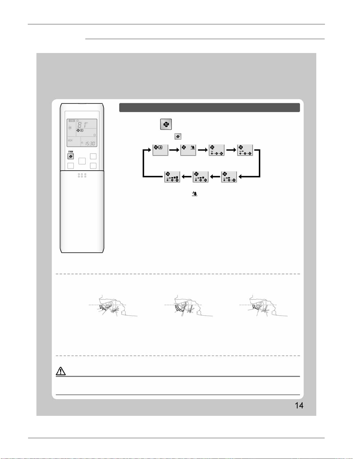
FTXS Series SiUS091133
63 Operation Manual
FTXS15/18/24/30/36LVJU
To adjust the airflow rate setting
Press .
• Each pressing of advances the airflow rate setting in sequence.
Auto
Indoor unit quiet
Low Middle low
High Middle high
Middle
• When the airflow is set to “ ”, indoor unit quiet operation will start and the noise
from the unit will become quieter.
• In indoor unit quiet operation, the airflow rate is set to a weak level.
• In DRY operation, the airflow rate setting is not variable.
Notes on the angles of the louvers
• The louvers swinging range depends on the operation. (See the figure.)
Note on 3-D airflow
• Using 3-D airflow circulates cold air, which tends to collected at the bottom of the room, and hot air, which tends to collect near the ceiling,
throughout the room, preventing areas of cold and hot developing.
Note on airflow rate setting
• At smaller airflow rates, the cooling (heating) effect is also smaller.
NOTE
CAUTION
• Always use a remote controller to adjust the angles of the louvers and fins. If you attempt to move the louvers and fins forcibly with hand when they
are swinging, the mechanism may be broken.
• Always use a remote controller to adjust the fins angles. Inside the air outlet, a fan is rotating at a high speed.
COOL and DRY operation
HEAT operation FAN operation
COMFORT AIRFLOW
COMFORT AIRFLOW
Upper limit
Upper limit
Upper limit
Lower limit
Lower limit
Lower limit
Stop operation
Stop operation
Stop operation
10˚
15˚
50˚
70˚
30˚
75˚
70˚
15˚
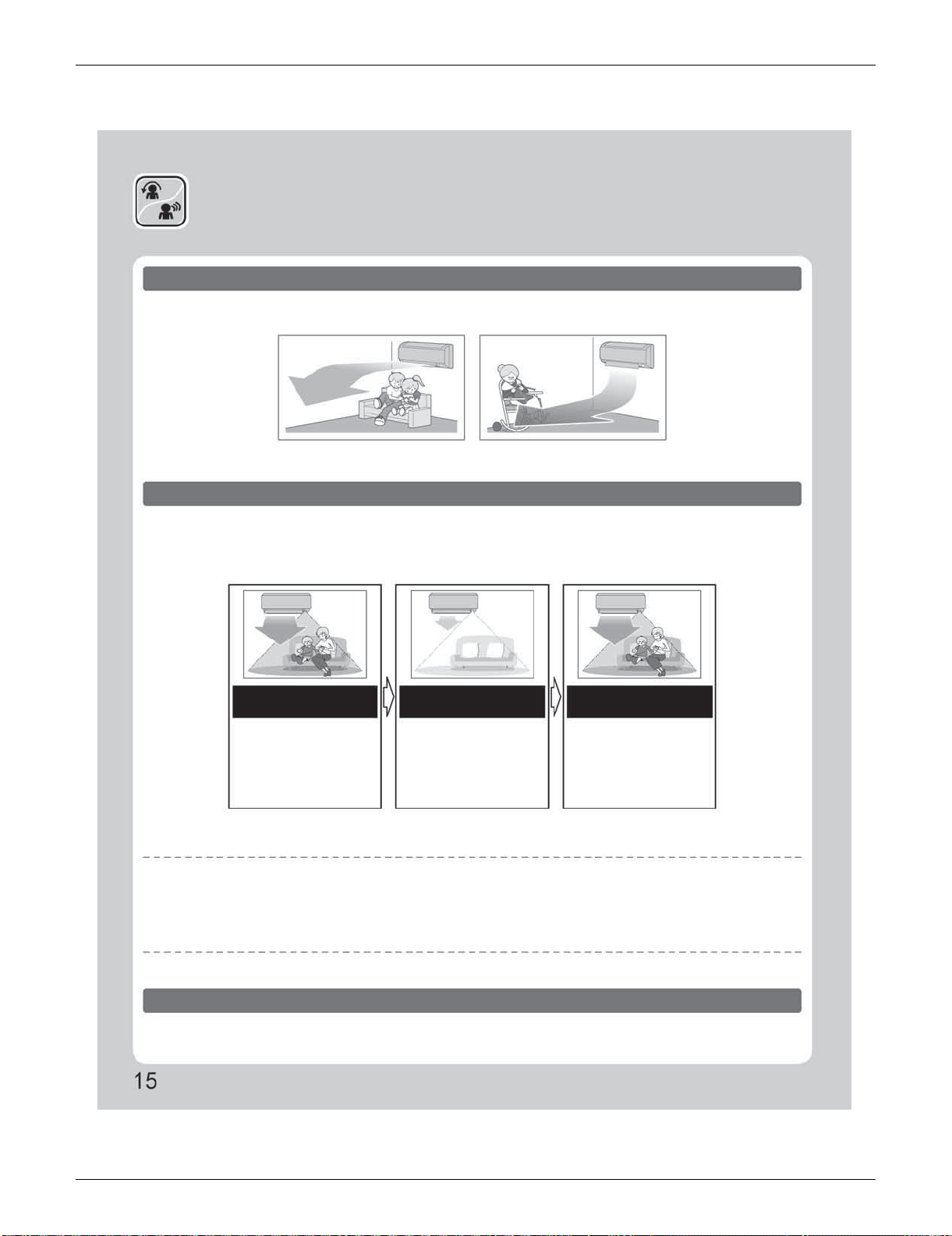
SiUS091133 FTXS Series
Operation Manual 64
2.4 COMFORT AIRFLOW / INTELLIGENT EYE Operation
COMFORT AIRFLOW /
INTELLIGENT EYE Operation
COMFORT AIRFLOW operation
INTELLIGENT EYE operation
The flow of air will be in the upward direction while in COOL operation and in the downward direction while in
HEAT operation, providing comfortable temperatures without air blowing directly on people.
“INTELLIGENT EYE” is the infrared sensor which detects human movement.
If no one is in the room for more than 20 minutes, the operation automatically changes to energy saving
operation.
COOL operation HEAT operation
[Example]
When someone is in
the room
When no one is in the
room
Someone is back in the
room
Normal operation
20 minutes after, start
energy saving
operation.
Back to normal
operation.
• The air conditioner is in
normal operation while the
sensor is detecting the
movement of people.
• The set temperature is
shifted in ±3.6°F (±2°C)
steps.
• The air conditioner will
return to normal operation
when the sensor detects the
movement of people again.
INTELLIGENT EYE operation is useful for energy saving
Energy saving operation
• If no presence detected in the room for 20 minutes, the energy saving operation will start.
• This operation changes the temperature –3.6°F (–2°C) in HEAT / +3.6°F (+2°C) in COOL / +3.6°F (+2°C) in DRY operation from set temperature.
When the room temperature exceeds 86°F (30°C), the operation changes the temperature +1.8°F (+1°C) in COOL / +1.8°F (+1°C) in DRY
operation from set temperature.
• This operation decreases the airflow rate slightly in FAN mode only.
Combination COMFORT AIRFLOW and INTELLIGENT EYE operation
The air conditioner can go into operation with the COMFORT AIRFLOW and INTELLIGENT EYE functions
combined.
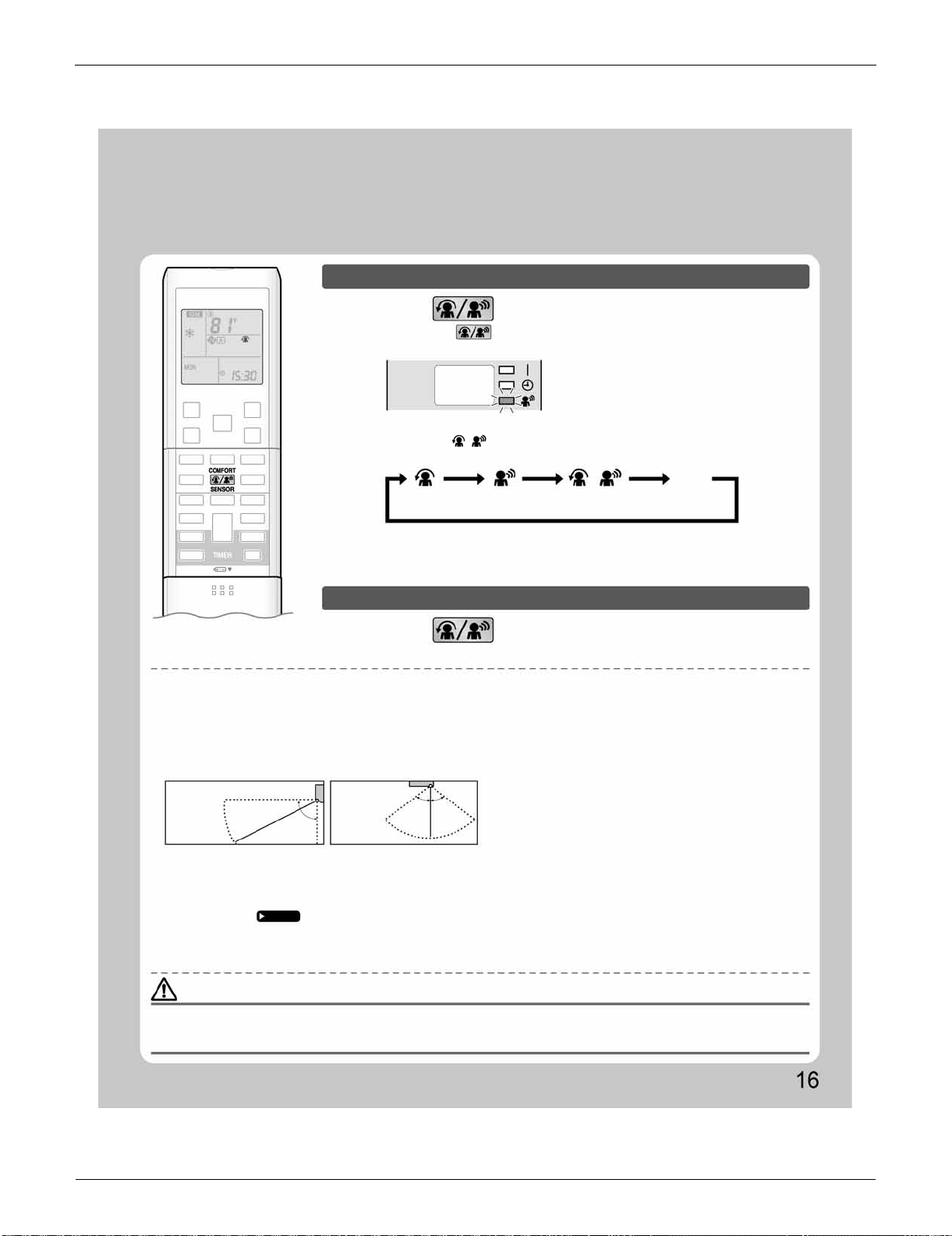
FTXS Series SiUS091133
65 Operation Manual
To start operation
Press and select the desired mode.
Press and select “blank” on the LCD.
• Each time the is pressed a different setting option is displayed on the LCD.
• The INTELLIGENT EYE lamp lights green.
• When the louvers (horizontal blades) are swinging, the operating as above will stop
movement of them.
• The lamp will be lit while human movements are detected.
• The INTELLIGENT EYE lamp goes off.
Display
COMFORT
AIRFLOW
INTELLIGENT
EYE
Combination
No Setting
blank
To cancel operation
NOTE
CAUTION
Notes on COMFORT AIRFLOW operation
• The louver position will change, preventing air from blowing directly on the occupants of the room.
• POWERFUL operation and COMFORT AIRFLOW operation cannot be used at the same time.
Priority is given to the function of whichever button is pressed last.
• The airflow rate will be set to AUTO. If the upper and lower airflow direction is selected, the COMFORT AIRFLOW function will be canceled.
Notes on INTELLIGENT EYE operation
• Application range is as follows.
• Sensor may not detect moving objects further than 23ft (7m) away. (Check the application range)
• Sensor detection sensitivity changes according to indoor unit location, the speed of passersby, temperature range, etc.
• The sensor also mistakenly detects pets, sunlight, fluttering curtains and light reflected off of mirrors as passersby.
• INTELLIGENT EYE operation will not go on during POWERFUL operation.
• NIGHT SET mode
Page 20
will not go on during use of INTELLIGENT EYE operation.
Notes on combination of COMFORT AIRFLOW operation and INTELLIGENT EYE operation
• The airflow rate will be set to AUTO. If the upper and lower airflow direction is selected, the COMFORT AIRFLOW operation will be canceled.
Priority is given to the function of whichever button is pressed last.
• Do not place large objects near the sensor.
Also keep heating units or humidifiers outside the sensor’s detection area. This sensor can detect undesirable objects.
• Do not hit or violently push the INTELLIGENT EYE sensor. This can lead to damage and malfunction.
Vertical angle 90˚
(Side view)
Horizontal
angle 110˚
(Top view)
23ft (7m)
90˚
55˚ 55˚
23ft
(7m)
• By selecting “ ” from the following icons, the air conditioner will be in COMFORT
AIRFLOW operation combined with INTELLIGENT EYE operation.
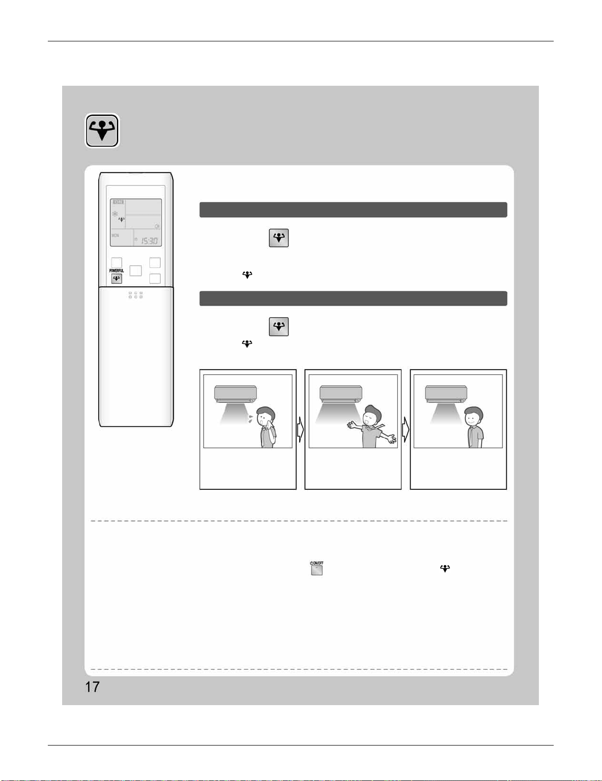
SiUS091133 FTXS Series
Operation Manual 66
2.5 POWERFUL Operation
POWERFUL Operation
POWERFUL operation quickly maximizes the cooling (heating) effect in any
operation mode. You can get the maximum capacity.
To start POWERFUL operation
To cancel POWERFUL operation
Press during operation.
Press again.
• POWERFUL operation ends in 20 minutes. Then the system automatically operates
again with the previous settings which were used before POWERFUL operation.
• “ ” is displayed on the LCD.
• “ ” is no longer displayed on the LCD.
• When you want to get the
cooling effect quickly, start
the POWERFUL operation.
• POWERFUL operation will
work for 20 minutes.
[Example]
Normal operation
POWERFUL operation
Back to normal
operation
NOTE
Notes on POWERFUL operation
• When using POWERFUL operation, there are some functions which are not available.
• POWERFUL operation cannot be used together with ECONO, COMFORT AIRFLOW or OUTDOOR UNIT QUIET operation.
Priority is given to the function of whichever button is pressed last.
• POWERFUL operation can only be set when the unit is running. Pressing causes the settings to be canceled, and “ ” is no longer
displayed on the LCD.
• POWERFUL operation will not increase the capacity of the air conditioner if the air conditioner is already in operation with its maximum capacity
demonstrated.
• In COOL, HEAT and AUTO operation
To maximize the cooling (heating) effect, the capacity of outdoor unit is increased and the airflow rate is fixed to the maximum setting.
The temperature and airflow settings are not variable.
• In DRY operation
The temperature setting is lowered by 4.5˚F (2.5˚C) and the airflow rate is slightly increased.
• In FAN operation
The airflow rate is fixed to the maximum setting.
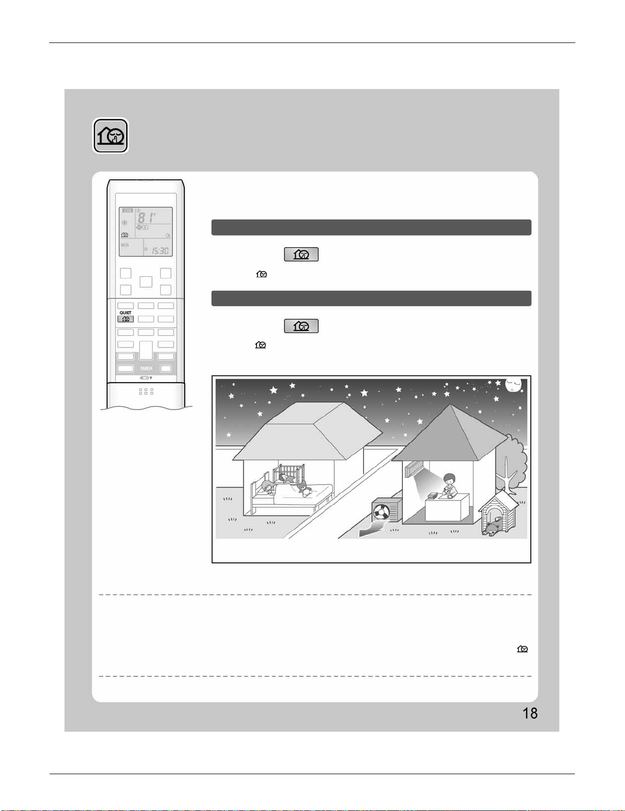
FTXS Series SiUS091133
67 Operation Manual
2.6 OUTDOOR UNIT QUIET Operation
OUTDOOR UNIT QUIET
Operation
OUTDOOR UNIT QUIET operation lowers the noise level of the outdoor unit by
changing the frequency and fan speed on the outdoor unit. This function is
convenient during the night.
To start OUTDOOR UNIT QUIET operation
To cancel OUTDOOR UNIT QUIET operation
Press .
Press again.
[Example] Using the OUTDOOR UNIT QUIET operation during the night.
• The noise level of the outdoor unit will be lower.
This is convenient in consideration of your neighbors.
NOTE
Notes on OUTDOOR UNIT QUIET operation
• This function is available in COOL, HEAT, and AUTO operation.
This is not available in FAN and DRY operation.
• POWERFUL operation and OUTDOOR UNIT QUIET operation cannot be used at the same time.
Priority is given to the function of whichever button is pressed last.
• Even the operation is stopped using the remote controller or the indoor unit ON/OFF switch when using OUTDOOR UNIT QUIET operation, “ ”
will remain on the remote controller display.
• OUTDOOR UNIT QUIET operation will drop neither the frequency nor fan speed if they have been already dropped low enough.
• “ ” is displayed on the LCD.
• “ ” is no longer displayed on the LCD.
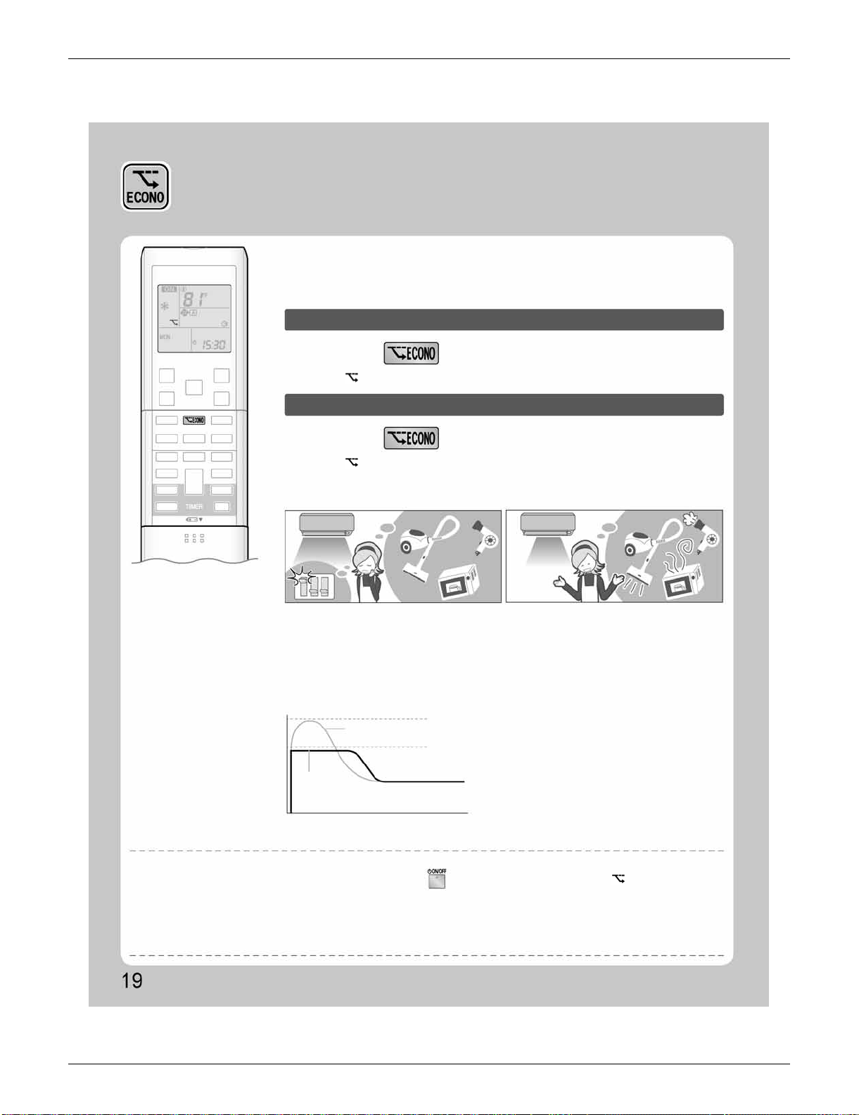
SiUS091133 FTXS Series
Operation Manual 68
2.7 ECONO Operation
ECONO Operation
ECONO operation is a function which enables efficient operation by limiting the
maximum power consumption value.
This function is useful for cases in which attention should be paid to ensure a
circuit breaker will not trip when the product runs alongside other appliances.
To start ECONO operation
To cancel ECONO operation
Press during operation.
Press again.
• “ ” is displayed on the LCD.
• “ ” is no longer displayed on the LCD.
[Example]
Normal operation
ECONO operation
• In case the air conditioner and other
appliances which require high power
consumption are used at same time, a circuit
breaker may trip if the air conditioner operate
with its maximum capacity.
Running current and
power consumption
From start up until set temperature is reached
Maximum during
normal operation
Maximum during
ECONO operation
Time
Normal
operation
ECONO
operation
• The maximum power consumption of the air
conditioner is limited by using ECONO operation.
The circuit breaker is unlikely to trip even if the
air conditioner and other appliances are used at
same time.
• This diagram is a representation for illustrative
purposes only.
The maximum running current and power
consumption of the air conditioner in ECONO
operation vary with the connecting outdoor
unit.
NOTE
Notes on ECONO operation
• ECONO operation can only be set when the unit is running. Pressing causes the settings to be canceled, and “ ” is no longer displayed
on the LCD.
• ECONO operation functions in AUTO, COOL, DRY, and HEAT operation.
• POWERFUL and ECONO operation cannot be used at the same time.
Priority is given to the function of whichever button is pressed last.
• If the level of power consumption is already low, ECONO operation will not drop the power consumption.
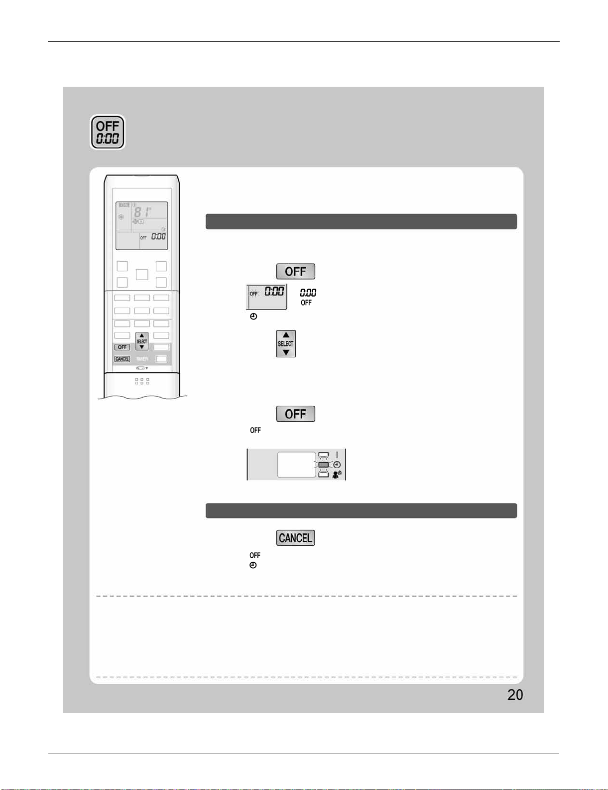
FTXS Series SiUS091133
69 Operation Manual
2.8 OFF TIMER Operation
OFF TIMER Operation
Timer functions are useful for automatically switching the air conditioner on or off
at night or in the morning. You can also use OFF TIMER and ON TIMER in
combination.
To use OFF TIMER operation
To cancel OFF TIMER operation
• Check that the clock is correct.
If not, set the clock to the present time.
• Each pressing of either button increases or decreases the time setting by 10 minutes.
Holding down either button changes the time setting rapidly.
• “ ” and setting time are displayed on the LCD.
• The TIMER lamp lights yellow.
• “ ” and setting time are no longer displayed on the LCD.
• “ ” and day of the week are displayed on the LCD.
• The TIMER lamp goes off.
• “ ” is no longer displayed on the LCD.
“ ” is displayed on the LCD.
“ ” blinks.
1.
Press .
Press .
3.
Press again.
2.
Press until the time setting reaches the
point you like.
Display
NOTE
Notes on TIMER operation
• When TIMER is set, the present time is not displayed.
• Once you set ON/OFF TIMER, the time setting is kept in the memory. The memory is canceled when remote controller batteries are replaced.
• When operating the unit via the ON/OFF TIMER, the actual length of operation may vary from the time entered by the user. (Maximum
approximately 10 minutes)
NIGHT SET mode
• When the OFF TIMER is set, the air conditioner automatically adjusts the temperature setting (0.9˚F (0.5˚C) up in COOL, 3.6˚F (2.0˚C) down in
HEAT) to prevent excessive cooling (heating) for your pleasant sleep.
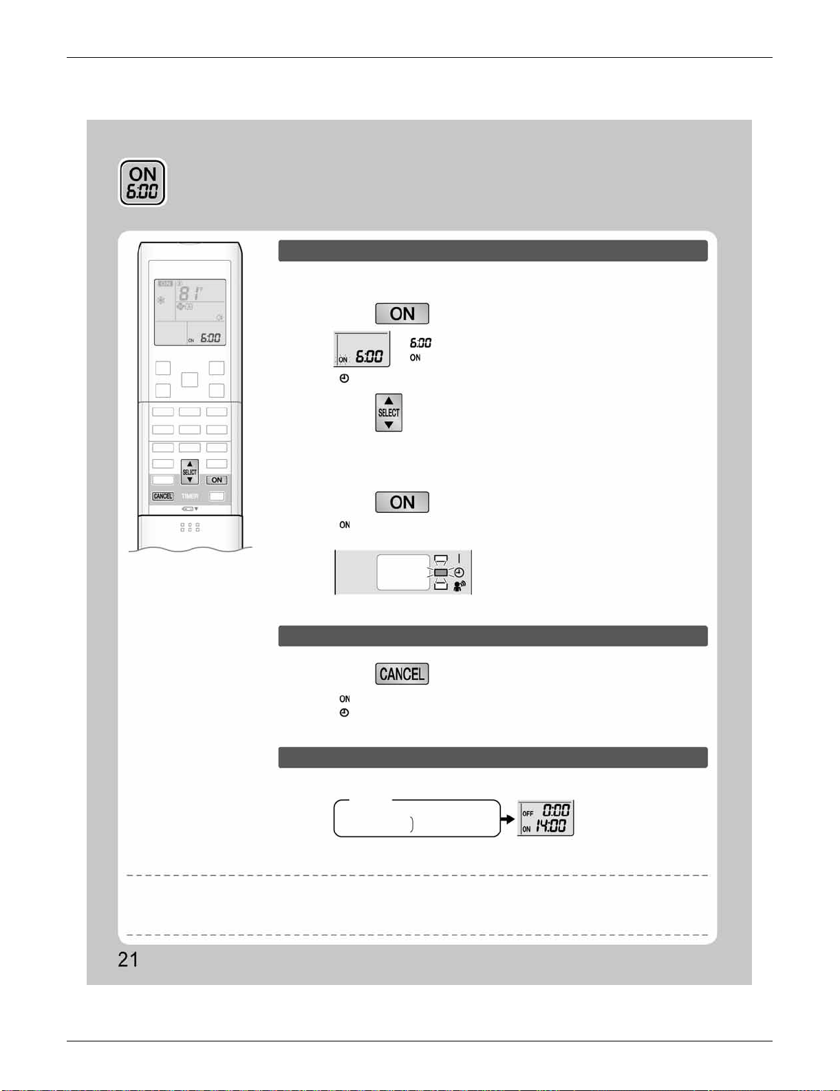
SiUS091133 FTXS Series
Operation Manual 70
2.9 ON TIMER Operation
ON TIMER Operation
1.
Press .
• “ ” and day of the week are no longer displayed on the LCD.
3.
Press again.
Display
Press .
• A sample setting for combining the 2 timers is shown below.
(Example)
Combined
NOTE
To use ON TIMER operation
To cancel ON TIMER operation
To combine ON TIMER and OFF TIMER
• Check that the clock is correct.
If not, set the clock to the present time.
“ ” is displayed on the LCD.
“ ” blinks.
2.
Press until the time setting reaches the
point you like.
• Each pressing of either button increases or decreases the time setting by 10 minutes.
Holding down either button changes the setting rapidly.
• “ ” and setting time are displayed on the LCD.
• The TIMER lamp lights yellow.
• “ ” and setting time are no longer displayed on the LCD.
• “ ” and day of the week are displayed on the LCD.
• The TIMER lamp goes off.
Present time: 23:00 (The unit operating)
OFF TIMER at 0:00
ON TIMER at 14:00
In the following cases, set the timer again.
• After a breaker has turned off.
• After a power failure.
• After replacing batteries in the remote controller.
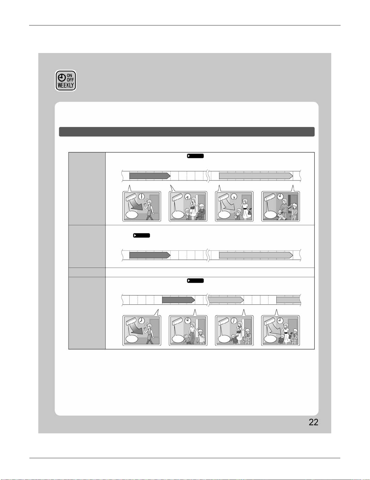
FTXS Series SiUS091133
71 Operation Manual
2.10 WEEKLY TIMER Operation
WEEKLY TIMER Operation
Up to 4 timer settings can be saved for each day of the week. It is convenient if the WEEKLY TIMER is set
according to the family’s life style.
Using in these cases of WEEKLY TIMER
Example: The same timer settings are made for the week from Monday through Friday while different timer settings are made
for the weekend.
[Monday]
[Tuesday]
to
[Friday]
[Saturday]
[Sunday]
Make timer settings up to programs 1-4.
No timer settings
Use the copy mode to make settings for Tuesday to Friday, because these settings are the same as those
for Monday.
Page 23
Make timer settings up to programs 1-4.
Page 23
Page 25
Program 1
77˚F (25˚C) 81˚F (27˚C)
ON
ON
6:00 8:30 17:30 22:00
OFF
OFF
ON
OFF
ON
OFF
ON
OFF
ON OFF
Program 2
OFF
Program 2
Program 3 Program 4
Program 1
77˚F (25˚C) 81˚F (27˚C)
ON
6:00 8:30 17:30 22:00
ON OFF
Program 3 Program 4
OFF
Program 2Program 1
77˚F (25˚C) 81˚F (27˚C)81˚F (27˚C)
ON
8:00 10:00 19:00 21:00
ONOFF
Program 3 Program 4
• Up to 4 reservations per day and 28 reservations per week can be set in the WEEKLY TIMER. The effective use of the copy
mode ensures ease of making reservations.
• The use of ON-ON-ON-ON settings, for example, makes it possible to schedule operating mode and set temperature changes.
Furthermore, by using OFF-OFF-OFF-OFF settings, only the turn off time of each day can be set. This will turn off the air
conditioner automatically if the user forgets to turn it off.
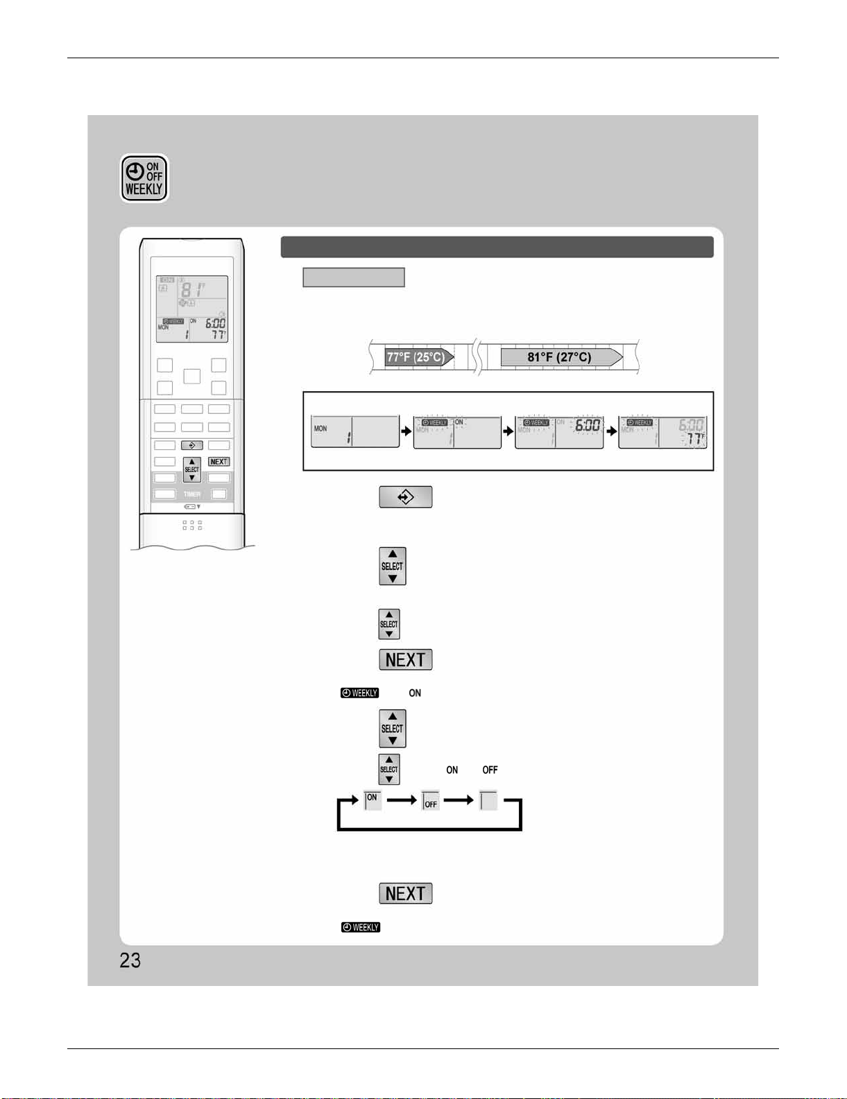
SiUS091133 FTXS Series
Operation Manual 72
WEEKLY TIMER Operation
To use WEEKLY TIMER operation
Setting mode
• Make sure the day of the week and time are set. If not, set the day of the week and time.
Program 1 Program 2 Program 3 Program 4
ON ON
6:00 8:30 17:30 22:00
OFF OFF
[Monday]
Setting Displays
Day and number settings ON/OFF settings Time settings Temperature settings
1.
Press .
2.
Press to select the desired day of the
week and reservation number.
3.
Press .
4.
Press to select the desired mode.
5.
Press .
• The day of the week and the reservation number of the current day will be displayed.
• 1 to 4 settings can be made per day.
• Pressing changes the reservation number and the day of the week.
• The day of the week and reservation number will be set.
• “ ” and “ ” blink.
• Pressing changes “ ” or “ ” setting in sequence.
• In case the reservation has already been set, selecting “blank” deletes the
reservation.
• Go to STEP
9
if “blank” is selected.
• The ON/OFF TIMER mode will be set.
• “ ” and the time blink.
ON TIMER OFF TIMER blank
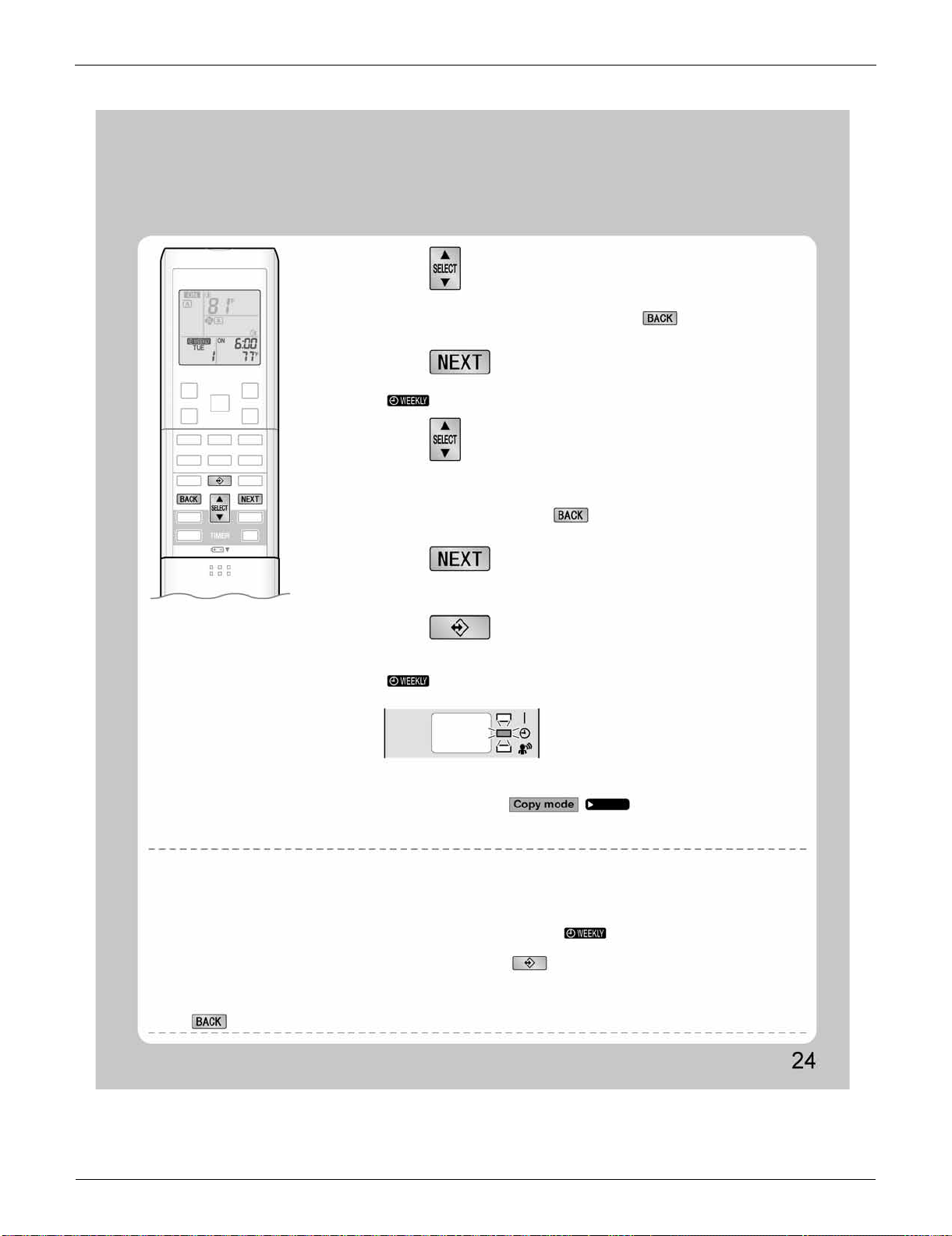
FTXS Series SiUS091133
73 Operation Manual
NOTE
7.
Press .
8.
Press to select the desired temperature.
6.
Press to select the desired time.
9.
Press .
10.
Press to complete the setting.
• The time can be set between 0:00 and 23:50 in 10 minute intervals.
• To return to the ON/OFF TIMER mode setting, press .
• Go to
STEP
9
when setting the OFF TIMER.
• The time will be set.
• “ ” and the temperature blink.
• The temperature can be set between 50˚F (10˚C) and 90˚F (32˚C).
Cooling: The unit operates at 64˚F (18˚C) even if it is set at 50 (10) to 63˚F (17˚C).
Heating: The unit operates at 86˚F (30˚C) even if it is set at 87 (31) to 90˚F (32˚C).
• To return to the time setting, press .
• The set temperature is only displayed when the mode setting is on.
• The temperature will be set and go to the next reservation setting.
• To continue further settings, repeat the procedure from
STEP
4
.
• Be sure to direct the remote controller toward the indoor unit and check for a receiving
tone and flashing the OPERATION lamp.
• “ ” is displayed on the LCD and WEEKLY TIMER operation is activated.
• The TIMER lamp lights yellow.
• A reservation made once can be easily copied and the same settings used for another
day of the week. Refer to .
Notes on WEEKLY TIMER operation
• Do not forget to set the clock on the remote controller first.
• The day of the week, ON/OFF TIMER mode, time and set temperature (only for ON TIMER mode) can be set with WEEKLY TIMER.
Other settings for ON TIMER are based on the settings just before the operation.
• Both WEEKLY TIMER and ON/OFF TIMER operation cannot be used at the same time. The ON/OFF TIMER operation has priority if it is set
while WEEKLY TIMER is still active. The WEEKLY TIMER will go into standby state, and
“ ” will be no longer displayed on the LCD.
When ON/OFF TIMER is up, the WEEKLY TIMER will automatically become active.
• Only the time and set temperature with the WEEKLY TIMER are sent with the . Set the WEEKLY TIMER only after setting the operation
mode, the airflow rate and the airflow direction ahead of time.
• Shutting the breaker off, power failure, and other similar events will render operation of the indoor unit’s internal clock inaccurate. Reset the
clock.
• The can be used only for the time and temperature settings. It cannot be used to go back to the reservation number.
Display
Page 25
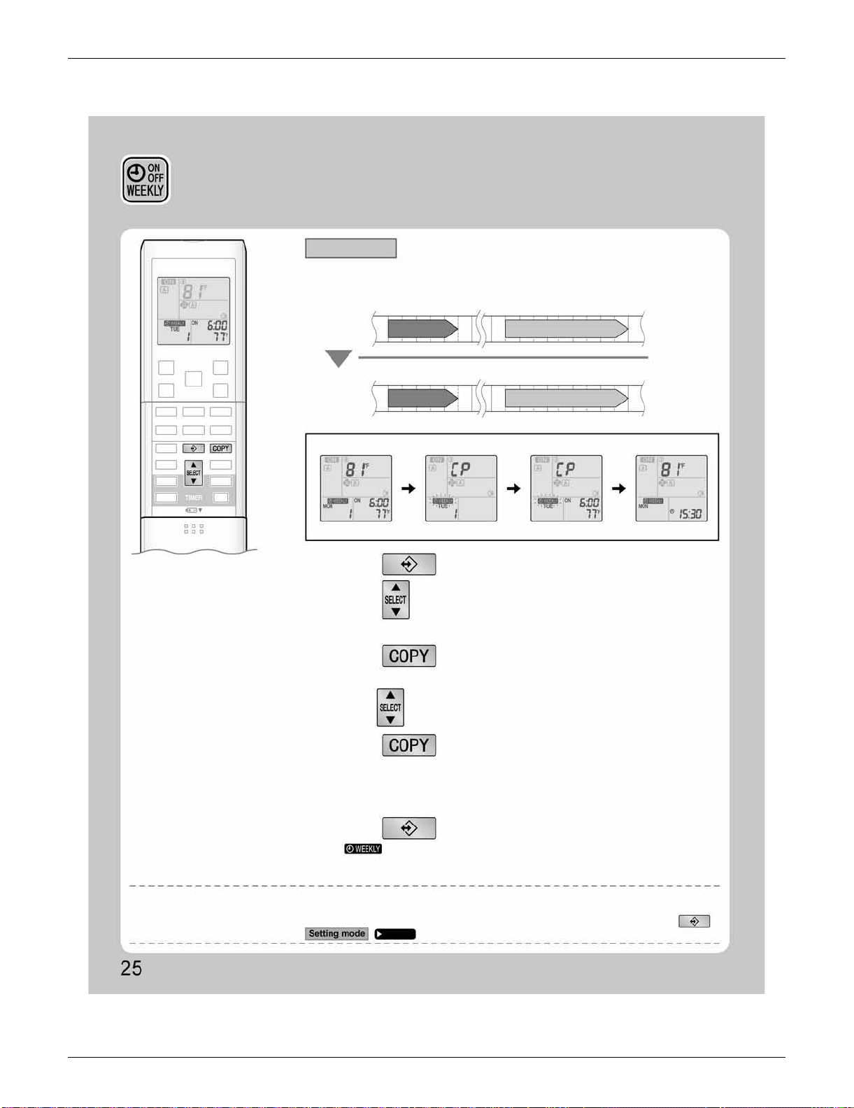
SiUS091133 FTXS Series
Operation Manual 74
WEEKLY TIMER Operation
• A reservation made once can be copied to another day of the week. The whole reservation
of the selected day of the week will be copied.
• The whole reservation of the selected day of the week will be copied.
• The reservation will be copied to the selected day of the week. The whole reservation
of the selected day of the week will be copied.
• To continue copying the settings to other days of the week, repeat
STEP
4
and
STEP
5
.
Program 1 Program 2 Program 3
ON OFF
Program 4
OFFON
Program 1 Program 2 Program 3
ON OFF
Program 4
OFFON
77˚F (25˚C)
77˚F (25˚C)
6:00 8:30 17:30 22:00
6:00 8:30 17:30 22:00
81˚F (27˚C)
81˚F (27˚C)
Setting Displays
1.
Press .
3.
Press .
5.
Press .
6.
Press to complete the setting.
2.
Press to confirm the day of the week to be
copied.
4.
Press to select the destination day of the week.
• “ ” is displayed on the LCD and WEEKLY TIMER operation is activated.
NOTE
Note on COPY MODE
•
The entire reservation of the source day of the week is copied in the copy mode.
In the case of making a reservation change for any day of the week individually after copying the content of weekly reservations, press
and change the settings in the steps of .
Confirmation display Copy display Paste display Normal display
[Monday]
COPY
Page 23
[Tuesday]
to
[Friday]
Copy mode
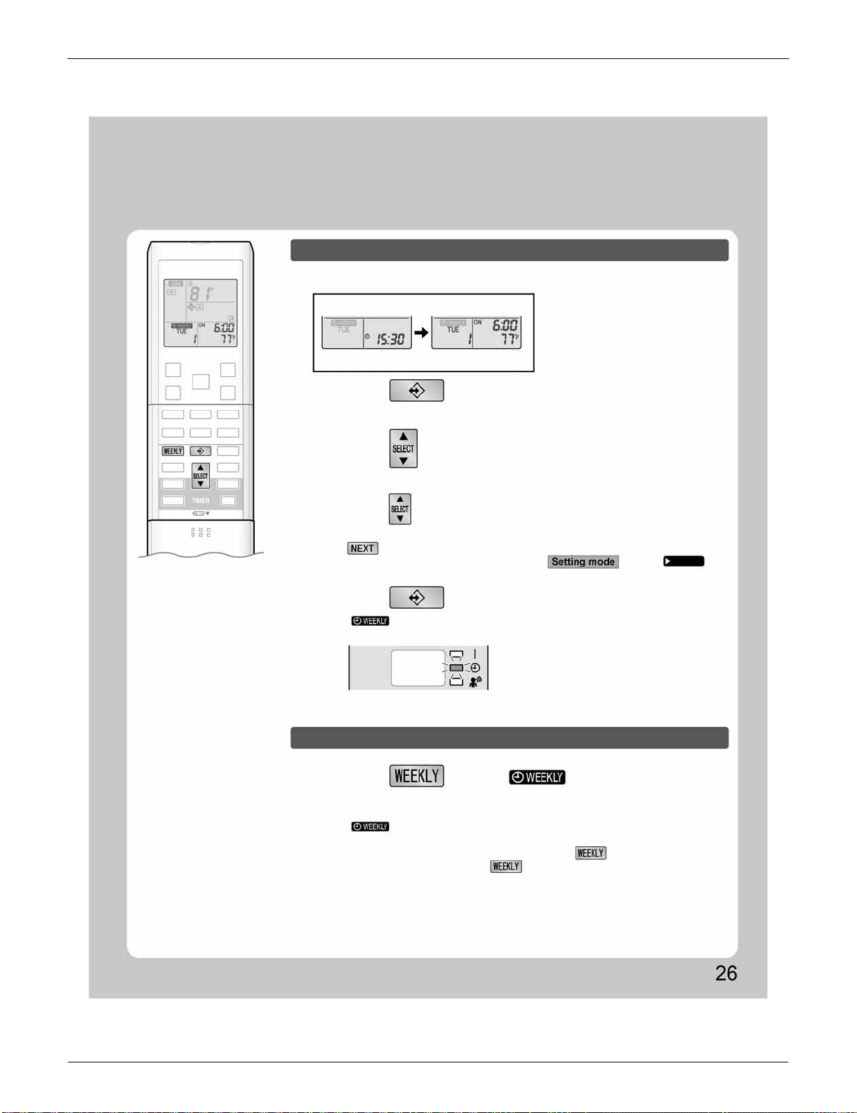
FTXS Series SiUS091133
75 Operation Manual
To deactivate WEEKLY TIMER operation
• The reservation can be confirmed.
• The day of the week and the reservation number of current day will be displayed.
• Pressing displays the reservation details.
• “ ” is displayed on the LCD and WEEKLY TIMER operation is activated.
• The TIMER lamp lights yellow.
• To change the confirmed reserved settings, select the reservation number and press
.
The mode is switched to setting mode. Go to
STEP
4
.
Setting Displays
Normal display Confirmation display
1.
Press .
2.
Press to select the day of the week and
the reservation number to be confirmed.
3.
Press to exit confirming mode.
Press while “ ” is displayed on
the LCD.
Display
• “ ” will be no longer displayed on the LCD.
• The TIMER lamp goes off.
• To reactivate the WEEKLY TIMER operation, press again.
• If a reservation deactivated with is activated once again, the last reservation
mode will be used.
Page 23
Confirming a reservation
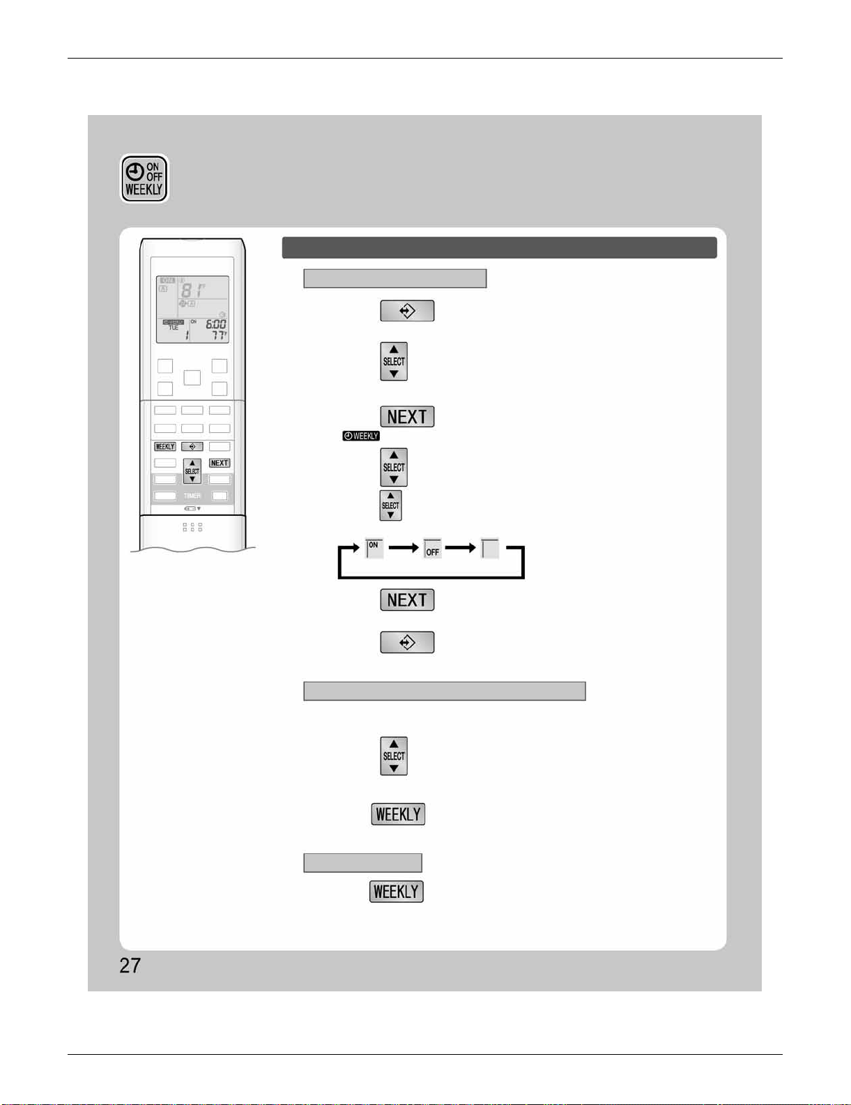
SiUS091133 FTXS Series
Operation Manual 76
To delete reservations
The individual reservation
All reservations
The reservations for each day of the week
1.
Press .
3.
Press .
5.
Press .
2.
Hold for 5 seconds.
Hold for 5 seconds while normal display.
6.
Press .
4.
Press and select “ blank ”.
2.
Press to select the day of the week and
the reservation number to be deleted.
• The day of the week and the reservation number will be displayed.
• Pressing changes ON/OFF TIMER mode.
• The reservation will be no setting with selecting “blank”.
• “ ” and “ON” or “OFF” blink.
• The selected reservation will be deleted.
• The reservation of the selected day of the week will be deleted.
• If there are still other reservations, WEEKLY TIMER operation will be activated.
• This function can be used for deleting reservations for each day of the week.
• It can be used while confirming or setting reservations.
• Be sure to direct the remote controller toward the indoor unit and check for a receiving tone.
• This operation is not effective on the setting display of WEEKLY TIMER.
• All reservations will be deleted.
ON TIMER OFF TIMER blank
1.
Press to select the day of the week to be
deleted.
WEEKLY TIMER Operation
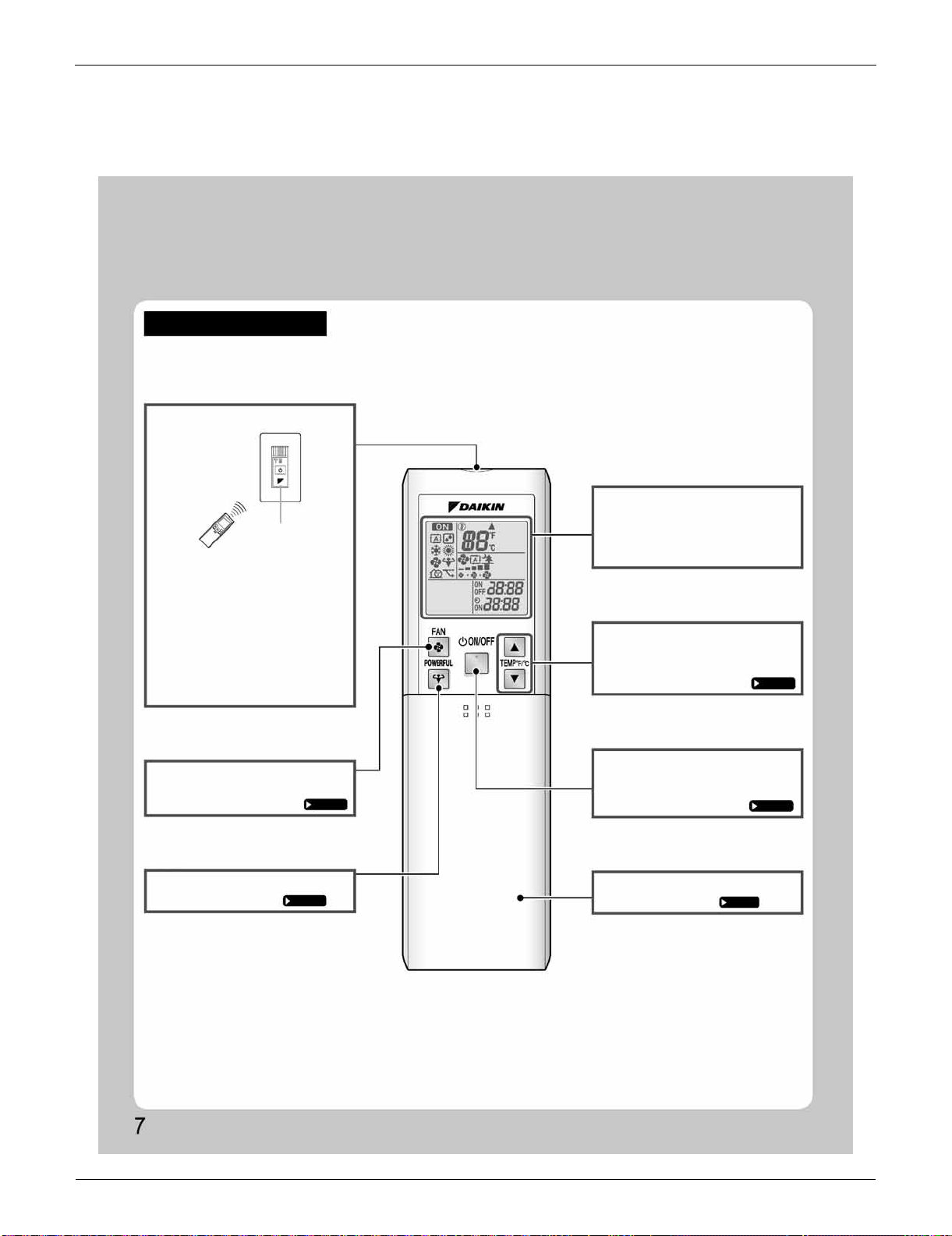
FDXS Series SiUS091133
77 Operation Manual
3. FDXS Series
3.1 Remote Controller
Names of Parts
Remote Controller
Signal transmitter
Receiver
FAN setting button
• Selects the airflow rate setting.
Page 13
POWERFUL button
• POWERFUL operation.
Page 14
Display (LCD)
• Changes the temperature setting.
Page 12
ON/OFF button
Page 11
Front cover
• Open the front cover.
Page 8
<ARC452A23>
• To use the remote controller, aim the
transmitter at the indoor unit. If there
is anything to block signals between
the unit and the remote controller,
such as a curtain, the unit will not
operate.
• Do not drop the remote controller.
Do not get it wet.
• The maximum distance for
communication is approximately 13ft
(4m).
TEMPERATURE
adjustment buttons
• Displays the current settings.
(In this illustration, each section is
shown with all its displays on for the
purpose of explanation.)
• Press this button once to start
operation.
Press once again to stop it.
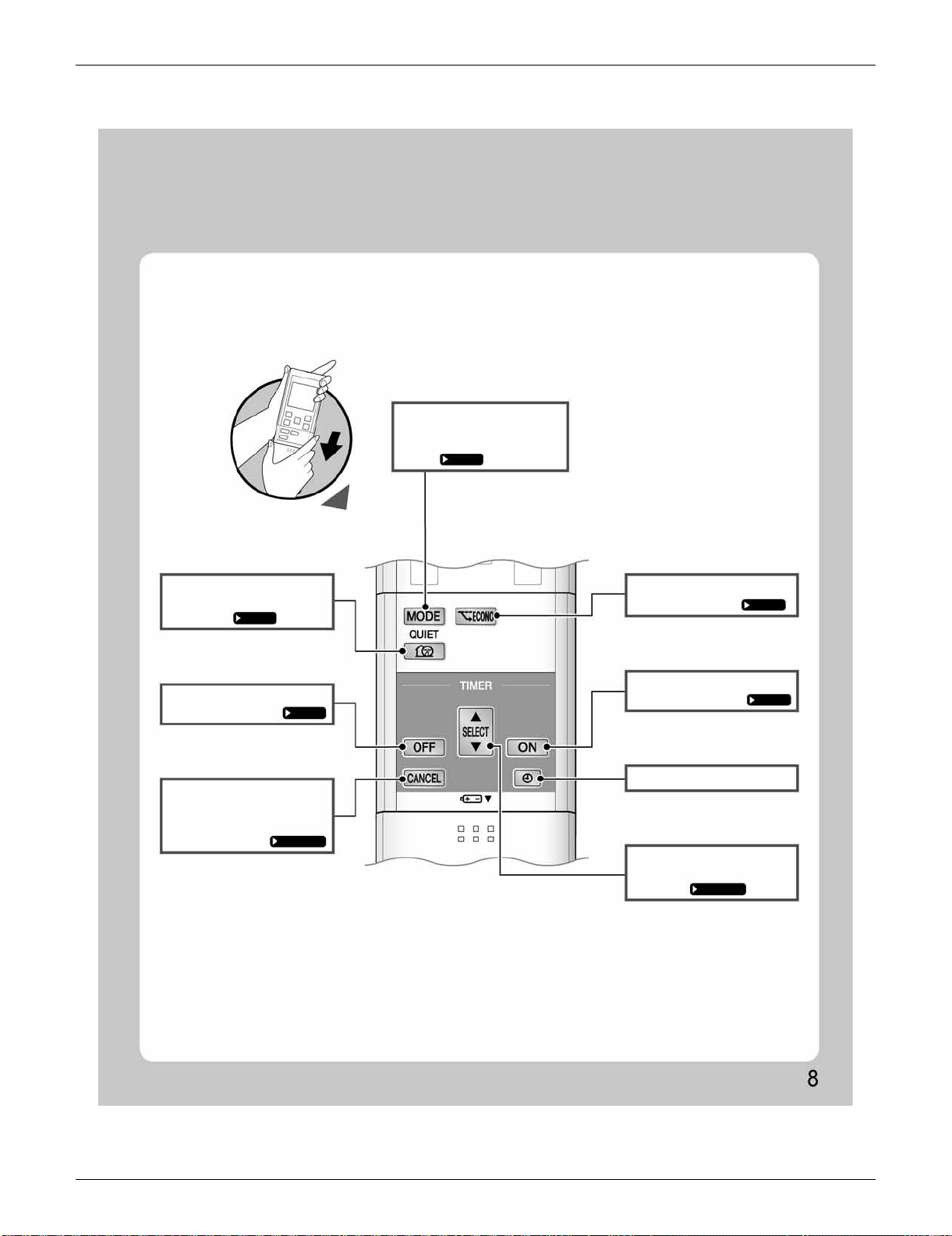
SiUS091133 FDXS Series
Operation Manual 78
ECONO button
• ECONO operation.
Page 16
ON TIMER button
Page 18
CLOCK button
SELECT button
Page 17,18
QUIET button
Page 15
OFF TIMER button
Page 17
• Cancels the timer setting.
Page 17,18
MODE selector button
Page 11
Open the front cover
• Selects the operation mode.
(AUTO/DRY/COOL/HEAT/
FAN)
• Changes the ON/OFF TIMER
settings.
TIMER CANCEL
button
• OUTDOOR UNIT QUIET
operation.
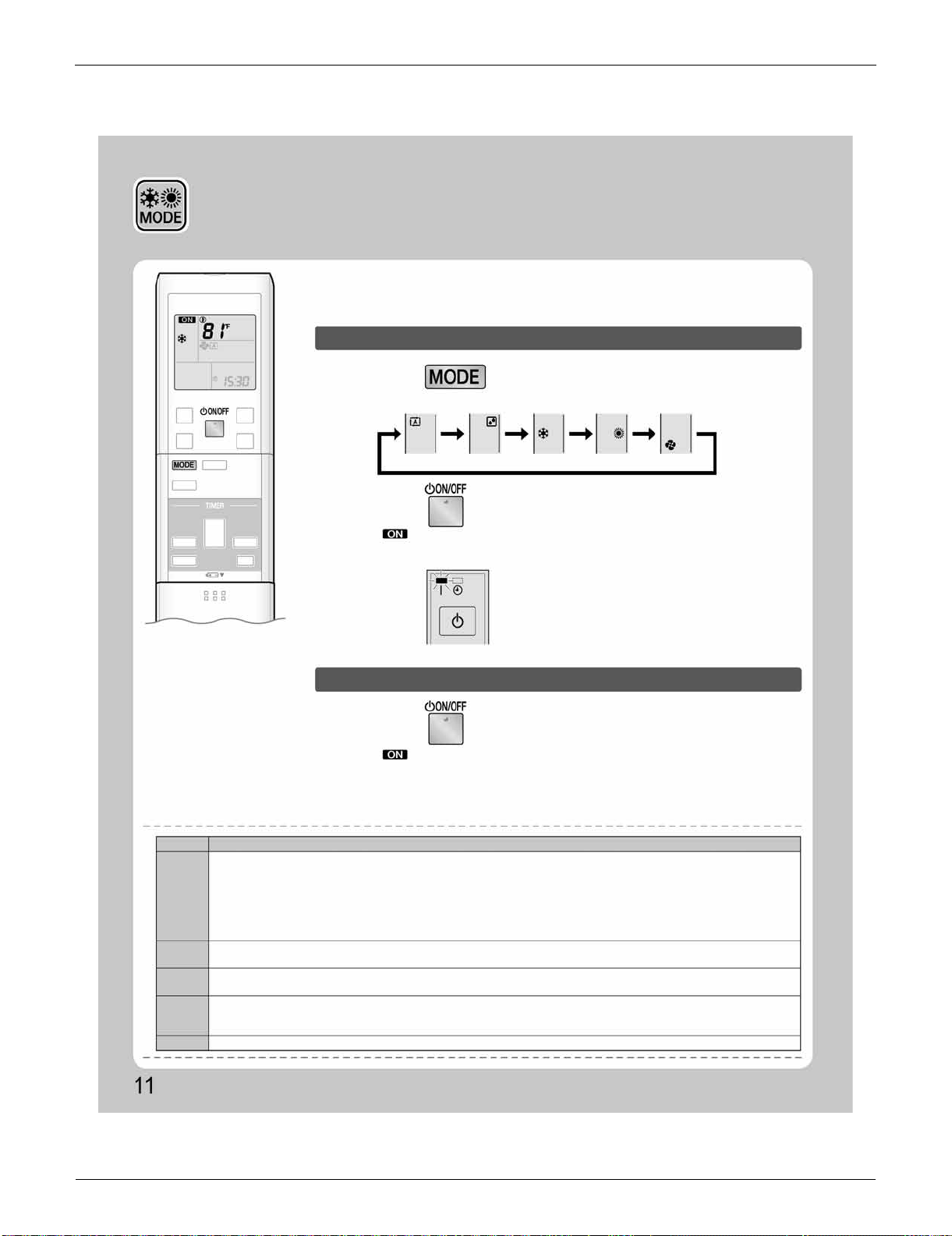
FDXS Series SiUS091133
79 Operation Manual
3.2 AUTO · DRY · COOL · HEAT · FAN Operation
1.
Press and select an operation mode.
• Each pressing of the button advances the mode setting in sequence.
AUTO DRY COOL HEAT FAN
2.
Press .
Display
NOTE
MODE
Notes on each operation mode
HEAT
COOL
DRY
AUTO
FAN
AUTO · DRY · COOL · HEAT ·
FAN Operation
The air conditioner operates with the operation mode of your choice.
From the next time on, the air conditioner will operate with the same operation
mode.
To start operation
• “ ” is displayed on the LCD.
• The OPERATION lamp lights green.
• “ ” is no longer displayed on the LCD.
• The OPERATION lamp goes off.
To stop operation
Press again.
•
Since this air conditioner heats the room by taking heat from outdoor air to indoors, the heating capacity becomes smaller in lower outdoor
temperatures. If the heating effect is insufficient, it is recommended to use another heating appliance in combination with the air conditioner.
• The heat pump system heats the room by circulating hot air around all parts of the room. After the start of HEAT operation, it takes
some time before the room gets warmer.
• In HEAT operation, frost may occur on the outdoor unit and lower the heating capacity. In that case, the system switches into
defrosting operation to take away the frost.
• During defrosting operation, hot air does not flow out of indoor unit.
• This air conditioner cools the room by releasing the heat in the room outside. Therefore, the cooling performance of the air
conditioner may be degraded if the outdoor temperature is high.
• The computer chip works to rid the room of humidity while maintaining the temperature as much as possible. It automatically
controls temperature and airflow rate, so manual adjustment of these functions is unavailable.
• In AUTO operation, the system selects an appropriate operation mode (COOL or HEAT) based on the room and outside
temperatures and starts the operation.
• The system automatically reselects setting at a regular interval to bring the room temperature to user-setting level.
• This mode is valid for fan only.
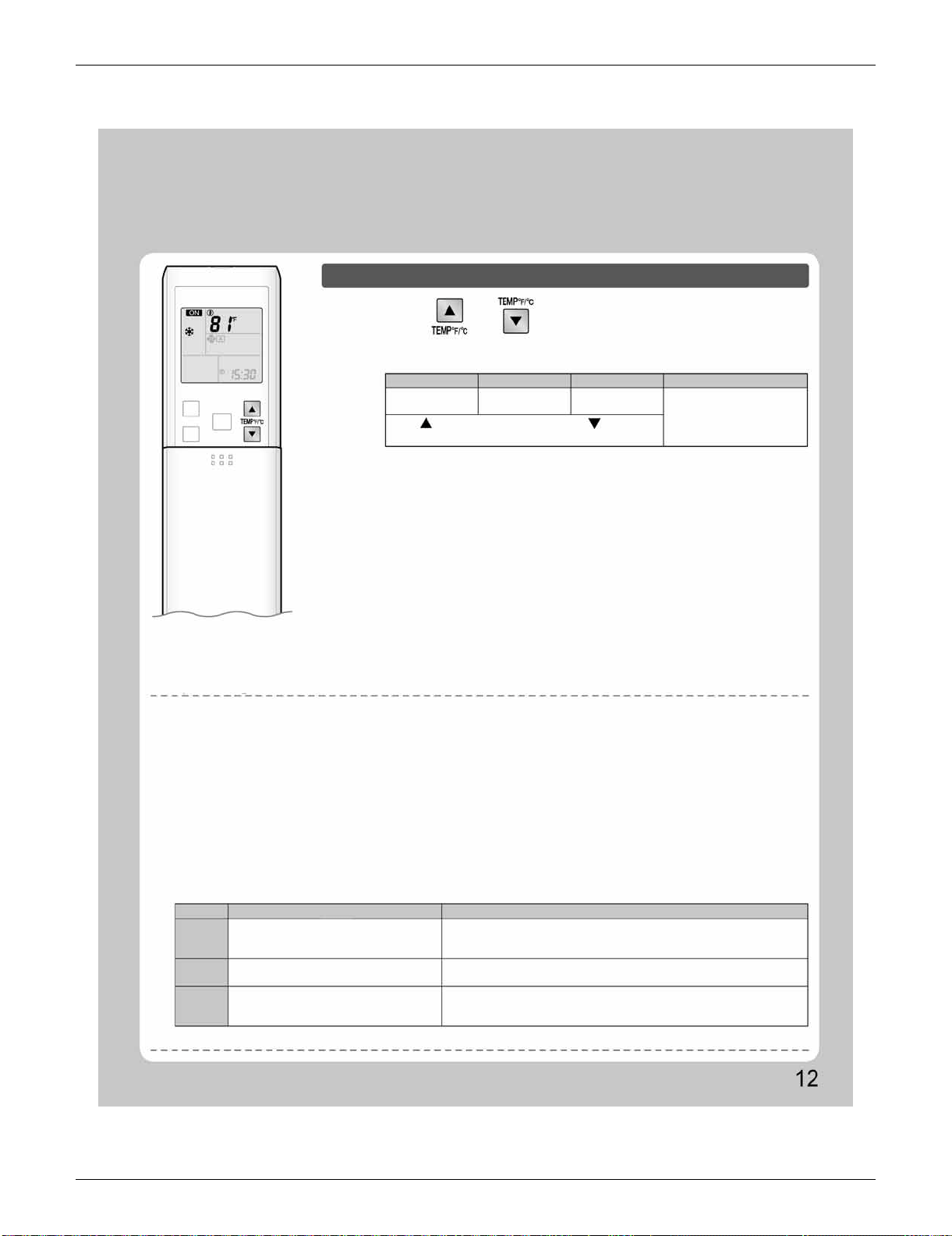
SiUS091133 FDXS Series
Operation Manual 80
COOL operation HEAT operation AUTO operation DRY or FAN operation
Operating conditions
MODE Operating conditions If operation is continued out of this range
COOL
HEAT
DRY
• Operation outside this humidity or temperature range may cause a safety device to disable the system.
Recommended temperature setting
• For cooling: 78-82˚F (26-28˚C)
• For heating: 68-75˚F (20-24˚C)
Tips for saving energy
• Be careful not to cool (heat) the room too much.
Keeping the temperature setting at a moderate level helps save energy.
• Cover windows with a blind or a curtain.
Blocking sunlight and air from outdoors increases the cooling (heating) effect.
• Clogged air filters cause inefficient operation and waste energy. Clean them once in about every 2 weeks.
Notes on the operating conditions
• The air conditioner always consumes a small amount of electricity even while it is not operating.
• If you are not going to use the air conditioner for a long period, for example in spring or autumn, turn the breaker off.
• Use the air conditioner in the following conditions.
Outdoor temperature : 50-115˚F (10-46˚C)
Indoor temperature : 64-90˚F (18-32˚C)
Indoor humidity : 80% max.
Outdoor temperature : 5-75˚F (–15-24˚C)
Indoor temperature : 50-86˚F (10-30˚C)
Outdoor temperature : 50-115˚F (10-46˚C)
Indoor temperature : 64-90˚F (18-32˚C)
Indoor humidity : 80% max.
• A safety device may work to stop the operation.
• Condensation may occur on the indoor unit and drip.
•
A safety device may work to stop the operation.
• A safety device may work to stop the operation.
• Condensation may occur on the indoor unit and drip.
To change the temperature setting
Press or .
• The displayed items on the LCD will change whenever either one of the buttons is
pressed.
The temperature setting is
not variable.
64-90˚F
(18-32˚C)
50-86˚F
(10-30˚C)
64-86˚F
(18-30˚C)
Press to raise the temperature and press to lower the
temperature.
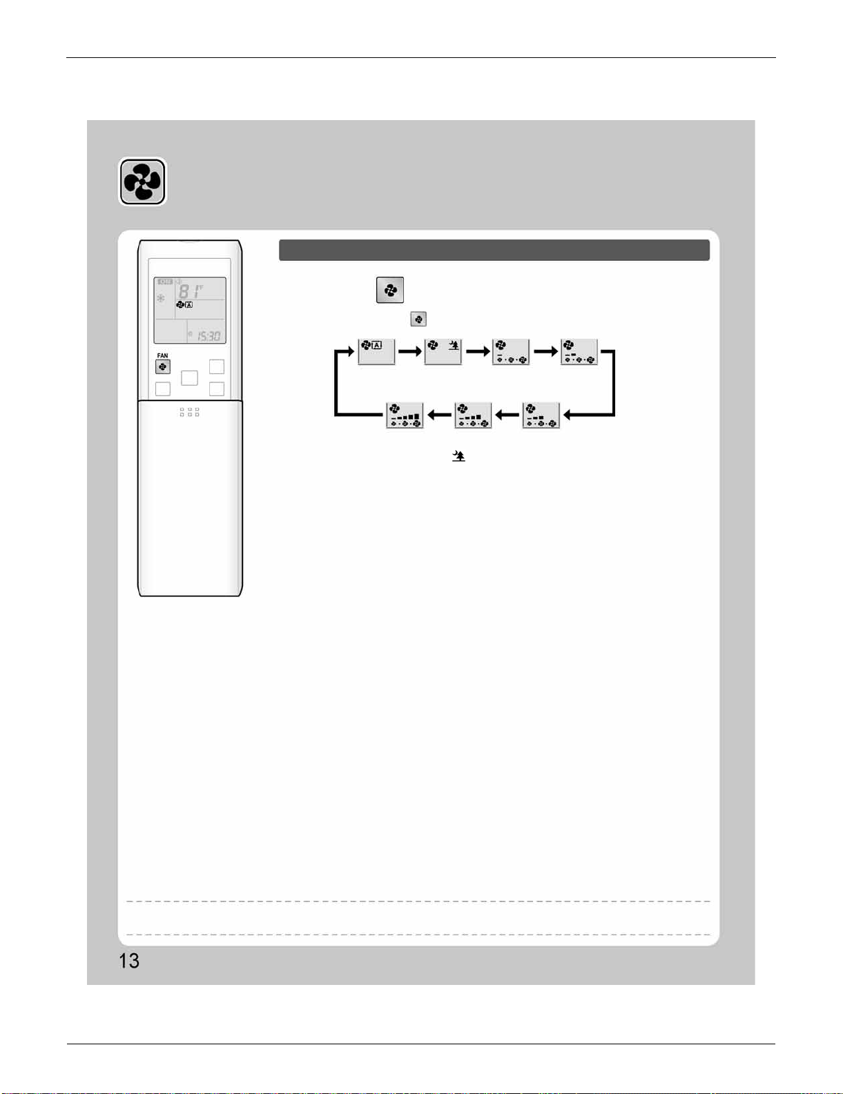
FDXS Series SiUS091133
81 Operation Manual
3.3 Adjusting the Airflow Rate
Adjusting the Airflow Rate
To adjust the airflow rate setting
Press .
•
Each pressing of advances the airflow rate setting in sequence.
•
At smaller airflow rates, the cooling (heating) effect is also smaller.
•
When the airflow is set to “ ”, indoor unit quiet operation will start and the noise
from the unit will become quieter.
•
In indoor unit quiet operation, the airflow rate is set to a weak level.
•
In DRY operation, the airflow rate setting is not variable.
Auto
Indoor unit quiet
Middle low
Low
High
Middle high
Middle
NOTE
Note on airflow rate setting

SiUS091133 FDXS Series
Operation Manual 82
3.4 POWERFUL Operation
POWERFUL Operation
POWERFUL operation quickly maximizes the cooling (heating) effect in any
operation mode. You can get the maximum capacity.
To start POWERFUL operation
To cancel POWERFUL operation
Normal operation
Press during operation.
Press again.
• POWERFUL operation ends in 20 minutes. Then the system automatically operates
again with the previous settings which were used before POWERFUL operation.
•
“ ” is displayed on the LCD.
• “ ” is no longer displayed on the LCD.
• When you want to get the
cooling effect quickly, start
the POWERFUL operation.
POWERFUL operation
• POWERFUL operation will
work for 20 minutes.
Back to normal
operation
[Example]
NOTE
Notes on POWERFUL operation
•
When using POWERFUL operation, there are some functions which are not available.
•
POWERFUL operation cannot be used together with ECONO and OUTDOOR UNIT QUIET operation.
Priority is given to the function of whichever button is pressed last.
•
POWERFUL Operation can only be set when the unit is running. Pressing the operation stop button causes the settings to be canceled, and
“ ” is no longer displayed on the LCD.
•
POWERFUL operation will not increase the capacity of the air conditioner if the air conditioner is already in operation with its maximum capacity
demonstrated.
•
In COOL, HEAT and AUTO operation
To maximize the cooling (heating) effect, the capacity of outdoor unit is increased and the airflow rate is fixed to the maximum setting.
The temperature and airflow settings are not variable.
•
In DRY operation
The temperature setting is lowered by 4.5˚F (2.5˚C) and the airflow rate is slightly increased.
•
In FAN operation
The airflow rate is fixed to the maximum setting.
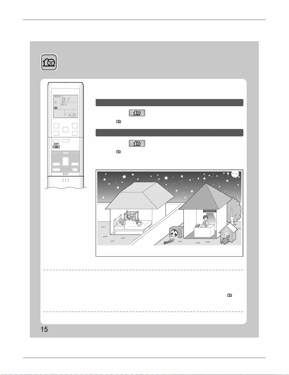
FDXS Series SiUS091133
83 Operation Manual
3.5 OUTDOOR UNIT QUIET Operation
OUTDOOR UNIT QUIET
Operation
OUTDOOR UNIT QUIET operation lowers the noise level of the outdoor unit by
changing the frequency and fan speed on the outdoor unit. This function is
convenient during night.
To start OUTDOOR UNIT QUIET operation
To cancel OUTDOOR UNIT QUIET operation
Press .
Press again.
•
“ ” is displayed on the LCD.
•
“ ” is no longer displayed on the LCD.
•
The noise level of the outdoor unit will be lower.
This is convenient in consideration of your neighbors.
[Example] Using the OUTDOOR UNIT QUIET operation during the night.
NOTE
Notes on OUTDOOR UNIT QUIET operation
•
This function is available in COOL, HEAT, and AUTO operation.
(This is not available in FAN and DRY operation.)
•
POWERFUL operation and OUTDOOR UNIT QUIET operation cannot be used at the same time.
Priority is given to the function of whichever button is pressed last.
•
If operation is stopped using the remote controller or the indoor unit ON/OFF switch when using OUTDOOR UNIT QUIET operation, “ ” will
remain on the remote controller display.
•
OUTDOOR UNIT QUIET operation will drop neither the frequency nor fan speed if the frequency and fan speed have been already dropped low
enough.
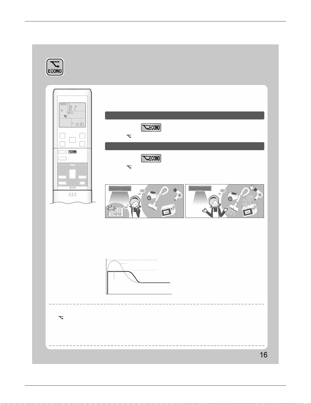
SiUS091133 FDXS Series
Operation Manual 84
3.6 ECONO Operation
ECONO Operation
ECONO operation is a function which enables efficient operation by limiting the
maximum power consumption value.
This function is useful for cases in which attention should be paid to ensure a
circuit breaker will not trip when the product runs alongside other appliances.
To start ECONO operation
To cancel ECONO operation
Press during operation.
Press again.
• “ ” is displayed on the LCD.
•
“ ” is no longer displayed on the LCD.
[Example]
Normal operation
ECONO operation
•
In case the air conditioner and other
appliances which require high power
consumption are used at same time, a circuit
breaker may trip if the air conditioner operate
with its maximum capacity.
•
The maximum power consumption of the air
conditioner is limited by using ECONO operation.
The circuit breaker is unlikely to trip even if the
air conditioner and other appliances are used at
same time.
•
This diagram is a representation for illustrative
purposes only.
The maximum running current and power
consumption of the air conditioner in ECONO
operation vary with the connecting outdoor
unit.
Running current and
power consumption
Maximum during
normal operation
Maximum during
ECONO operation
Normal
operation
ECONO
operation
From start up until set temperature is reached
Time
NOTE
Notes on ECONO operation
•
ECONO operation can only be set when the unit is running. Pressing the operation stop button causes the settings to be canceled, and the
“ ” is no longer displayed on the LCD.
•
ECONO operation is a function which enables efficient operation by limiting the power consumption of the outdoor unit (operating frequency).
•
ECONO operation functions in AUTO, COOL, DRY, and HEAT operation.
•
POWERFUL and ECONO operation cannot be used at the same time.
Priority is given to the function of whichever button is pressed last.
•
If the level of power consumption is already low, ECONO operation will not drop the power consumption.
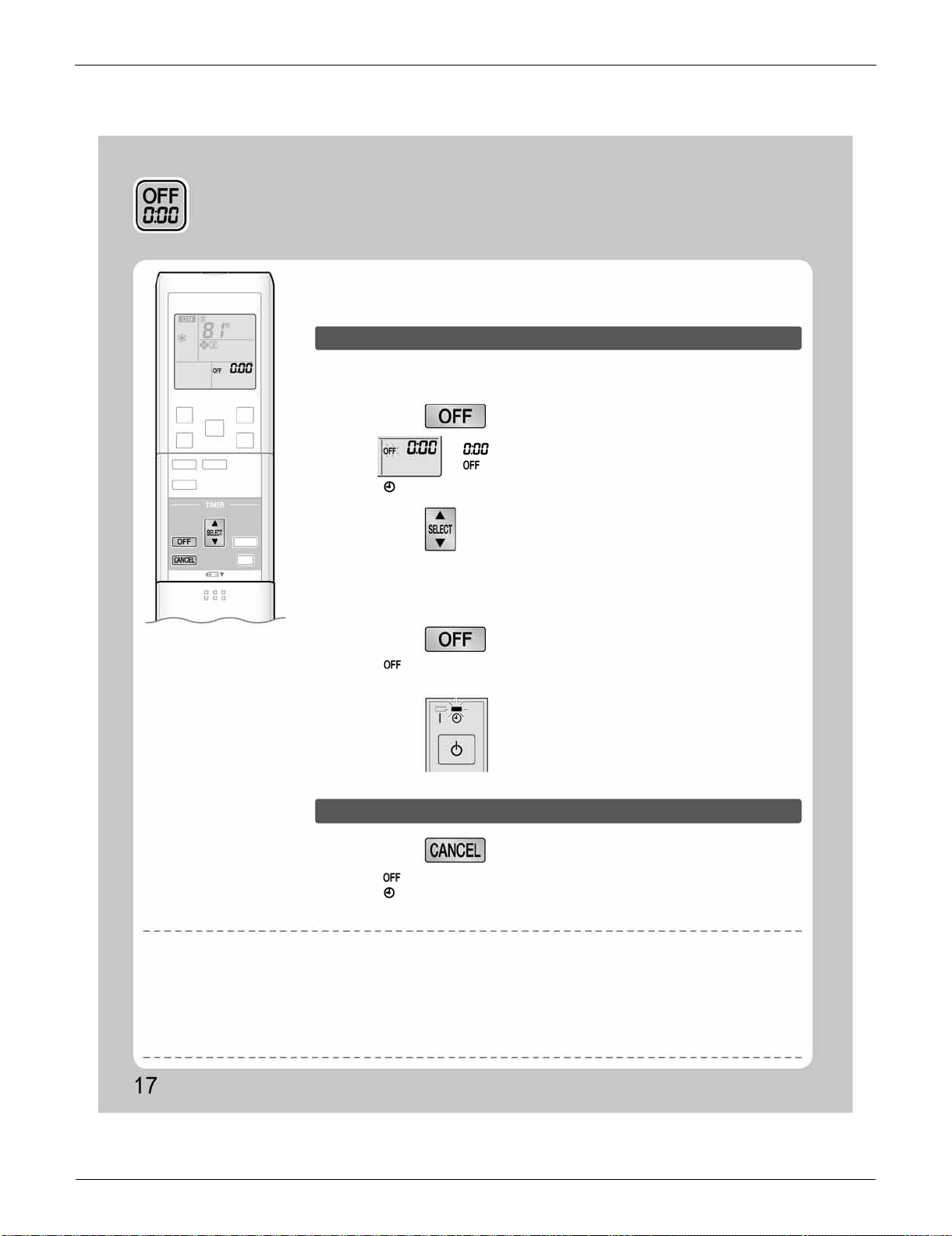
FDXS Series SiUS091133
85 Operation Manual
3.7 OFF TIMER Operation
OFF TIMER Operation
Timer functions are useful for automatically switching the air conditioner on or off
at night or in the morning. You can also use OFF TIMER and ON TIMER in
combination.
To use OFF TIMER operation
To cancel OFF TIMER operation
•
Check that the clock is correct.
If not, set the clock to the present time.
1.
Press .
“ ” is displayed on the LCD.
“ ” blinks.
• “ ” is no longer displayed on the LCD.
•
Each pressing of either button increases or decreases the time setting by 10 minutes.
Holding down either button changes the time setting rapidly.
• “ ” and setting time are displayed on the LCD.
• The TIMER lamp lights yellow.
• “ ” and setting time are no longer displayed on the LCD.
• “ ” and day of the week are displayed on the LCD.
• The TIMER lamp goes off.
• When TIMER is set, the present time is not displayed.
• Once you set ON/OFF TIMER, the time setting is kept in the memory. The memory is canceled when remote controller batteries are replaced.
• When operating the unit via the ON/OFF TIMER, the actual length of operation may vary from the time entered by the user. (Maximum
approximately 10 minutes)
• When the OFF TIMER is set, the air conditioner automatically adjusts the temperature setting (0.9˚F (0.5˚C) up in COOL, 3.6˚F (2.0˚C) down in
HEAT) to prevent excessive cooling (heating) for your pleasant sleep.
2.
Press until the time setting reaches the
point you like.
3.
Press again.
Press .
Display
NOTE
Notes on TIMER operation
NIGHT SET mode
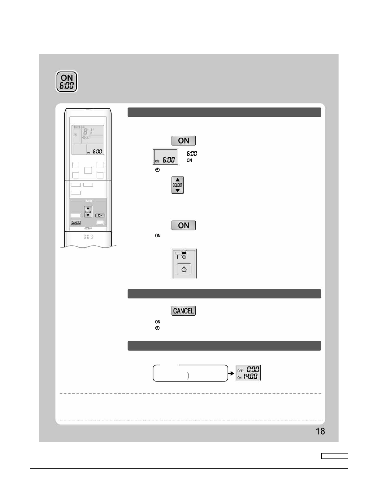
SiUS091133 FDXS Series
Operation Manual 86
3.8 ON TIMER Operation
ON TIMER Operation
To use ON TIMER operation
•
Check that the clock is correct.
If not, set the clock to the present time.
1.
Press .
“ ” is displayed on the LCD.
“ ” blinks.
• “ ” is no longer displayed on the LCD.
2.
Press until the time setting reaches the
point you like.
• Each pressing of either button increases or decreases the time setting by 10 minutes.
Holding down either button changes the setting rapidly.
3.
Press again.
• “ ” and setting time are displayed on the LCD.
• The TIMER lamp lights yellow.
Display
To cancel ON TIMER operation
To combine ON TIMER and OFF TIMER
Press .
• “ ” and setting time are no longer displayed on the LCD.
• “ ” and day of the week are displayed on the LCD.
• The TIMER lamp goes off.
• A sample setting for combining the 2 timers is shown below.
(Example)
Present time: 23:00 (The unit operating)
OFF TIMER at 0:00
Combined
ON TIMER at 14:00
NOTE
• After a breaker has turned off.
• After a power failure.
• After replacing batteries in the remote controller.
In the following cases, set the timer again.
3P297290-3

SiUS091133
87 Service Diagnosis
Part 6
Service Diagnosis
1. Troubleshooting with LED.........................................................................89
1.1 Indoor Unit..................................................................................................89
1.2 Outdoor Unit...............................................................................................89
2. Problem Symptoms and Measures...........................................................90
3. Service Check Function............................................................................91
4. Troubleshooting ........................................................................................94
4.1 Error Codes and Description......................................................................94
4.2 Indoor Unit PCB Abnormality .....................................................................95
4.3 Freeze-up Protection Control or Heating Peak-cut Control........................ 97
4.4 Fan Motor or Related Abnormality .............................................................99
4.5 Thermistor or Related Abnormality (Indoor Unit)......................................103
4.6 Refrigerant Shortage................................................................................104
4.7 Low-voltage Detection or Over-voltage Detection....................................107
4.8 Signal Transmission Error (between Indoor Unit and Outdoor Unit)........109
4.9 Signal Transmission Error on Outdoor Unit PCB
(24/30/36 Class Only)...............................................................................111
4.10 Unspecified Voltage (between Indoor Unit and Outdoor Unit) .................112
4.11 Outdoor Unit PCB Abnormality.................................................................113
4.12 OL Activation (Compressor Overload) .....................................................115
4.13 Compressor Lock.....................................................................................116
4.14 DC Fan Lock ............................................................................................117
4.15 Input Overcurrent Detection.....................................................................118
4.16 FourWay Valve Abnormality..................................................................... 119
4.17 Discharge Pipe Temperature Control.......................................................121
4.18 High Pressure Control in Cooling.............................................................123
4.19 Compressor System Sensor Abnormality ................................................125
4.20 Position Sensor Abnormality....................................................................128
4.21 DC Voltage / Current Sensor Abnormality (09/12 Class Only).................131
4.22 CT or Related Abnormality (24/30/36 Class Only)...................................132
4.23 Thermistor or Related Abnormality (Outdoor Unit)...................................134
4.24 Electrical Box Temperature Rise.............................................................. 136
4.25 Radiation Fin Temperature Rise ..............................................................138
4.26 Output Overcurrent Detection ..................................................................140
5. Check......................................................................................................142
5.1 Thermistor Resistance Check..................................................................142
5.2 Fan Motor Connector Output Check ........................................................143
5.3 Hall IC Check ...........................................................................................143
5.4 Power Supply Waveforms Check.............................................................144
5.5 Electronic Expansion Valve Check...........................................................144
5.6 FourWay Valve Performance Check........................................................145
5.7 Inverter Units Refrigerant System Check.................................................145

SiUS091133
Service Diagnosis 88
5.8 “Inverter Checker” Check.........................................................................146
5.9 Rotation Pulse Check on the Outdoor Unit PCB......................................148
5.10 Installation Condition Check.....................................................................149
5.11 Discharge Pressure Check.......................................................................150
5.12 Outdoor Fan System Check.....................................................................150
5.13 Main Circuit Short Check..........................................................................151
5.14 Capacitor Voltage Check..........................................................................152
5.15 Power Module Check...............................................................................153
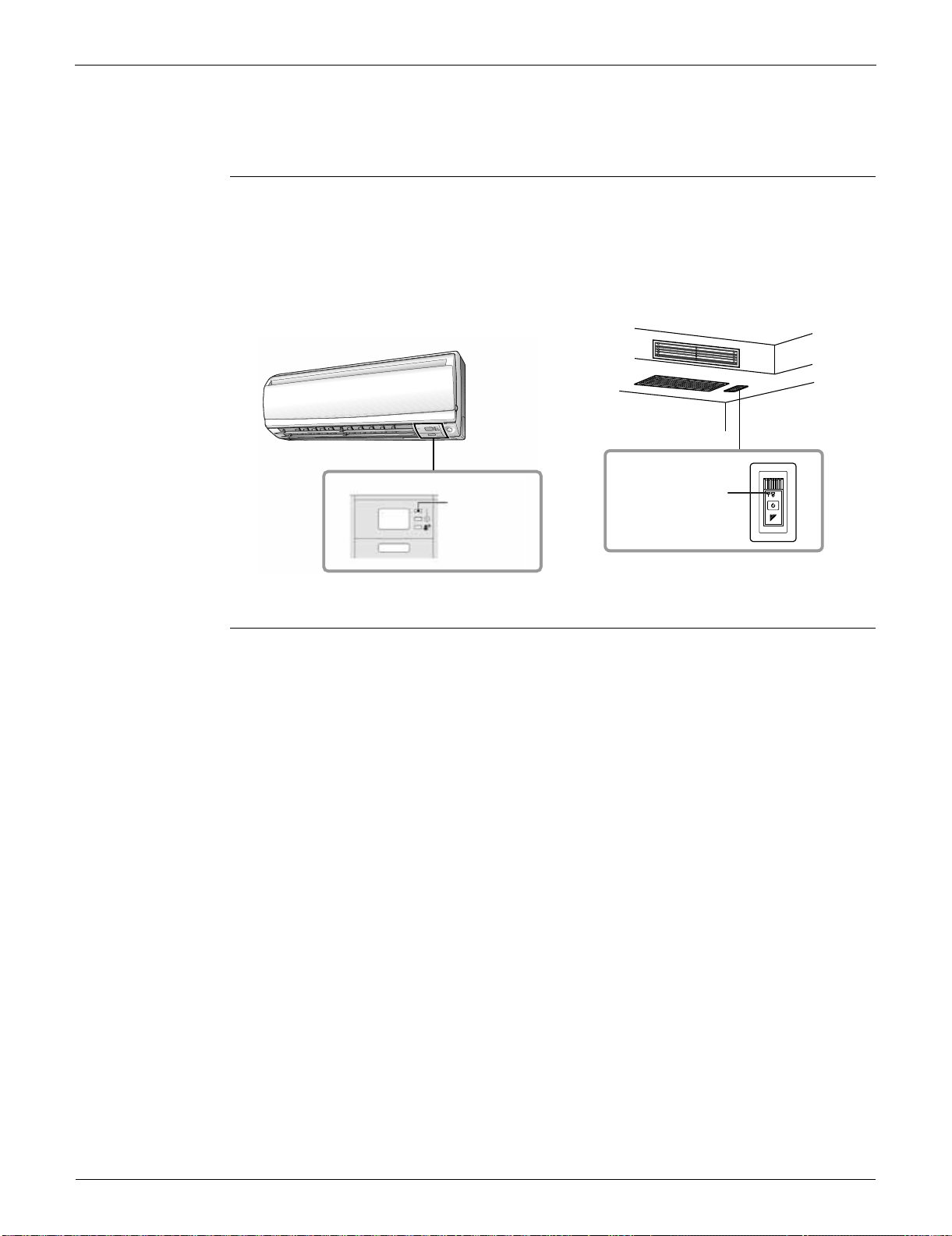
Troubleshooting with LED SiUS091133
89 Service Diagnosis
1. Troubleshooting with LED
1.1 Indoor Unit
Operation Lamp The operation lamp blinks when any of the following errors is detected.
1. When a protection device of the indoor or outdoor unit is activated, or when the thermistor
malfunctions.
2. When a signal transmission error occurs between the indoor and outdoor units.
In either case, conduct the diagnostic procedure described in the following pages.
Service Monitor The indoor unit has one green LED (LED A) on the control PCB. When the microcomputer works in
order, the LED A blinks.
1.2 Outdoor Unit
The outdoor unit has one green LED (LED A) on the PCB. When the microcomputer works in order,
the LED A blinks.
FTXS series
(Ex. 09/12 class)
FDXS series
(R13534)
Operation lamp
(green)
Operation lamp
(green)
(R16589)
SiUS091133 Problem Symptoms and Measures
Service Diagnosis 90
2. Problem Symptoms and Measures
Symptom Check Item Details of Measure Reference
Page
The unit does not operate. Check the power supply. Check if the rated voltage is supplied. —
Check the type of the indoor unit. Check if the indoor unit type is compatible with
the outdoor unit.
—
Check the outdoor temperature. Heating operation cannot be used when the
outdoor temperature is 24°C (75.2°F) or higher,
and cooling operation cannot be used when the
outdoor temperature is below 10°C (50°F).
—
Diagnose with remote controller
indication.
—
94
Check the remote controller
addresses.
Check if address settings for the remote
controller and indoor unit are correct.
388
Operation sometimes
stops.
Check the power supply. A power failure of 2 to 10 cycles stops air
conditioner operation. (Operation lamp OFF)
—
Check the outdoor temperature. Heating operation cannot be used when the
outdoor temperature is 24°C (75.2°F) or higher,
and cooling operation cannot be used when the
outdoor temperature is below 10°C (50°F).
—
Diagnose with remote controller
indication.
—
94
The unit operates but does
not cool, or does not heat.
Check for wiring and piping errors in
the connection between the indoor
unit and outdoor unit.
—
—
Check for thermistor detection errors. Check if the thermistor is mounted securely. —
Check for faulty operation of the
electronic expansion valve.
Set the unit to cooling operation, and check the
temperature of the liquid pipe to see if the
electronic expansion valve works.
—
Diagnose with remote controller
indication.
—
94
Diagnose by service port pressure
and operating current.
Check for refrigerant shortage. 104
operating noise and
vibrations
Check the output voltage of the
power module.
—
153
Check the power module. — —
Check the installation condition. Check if the required spaces for installation
(specified in the installation manual) are
provided.
—
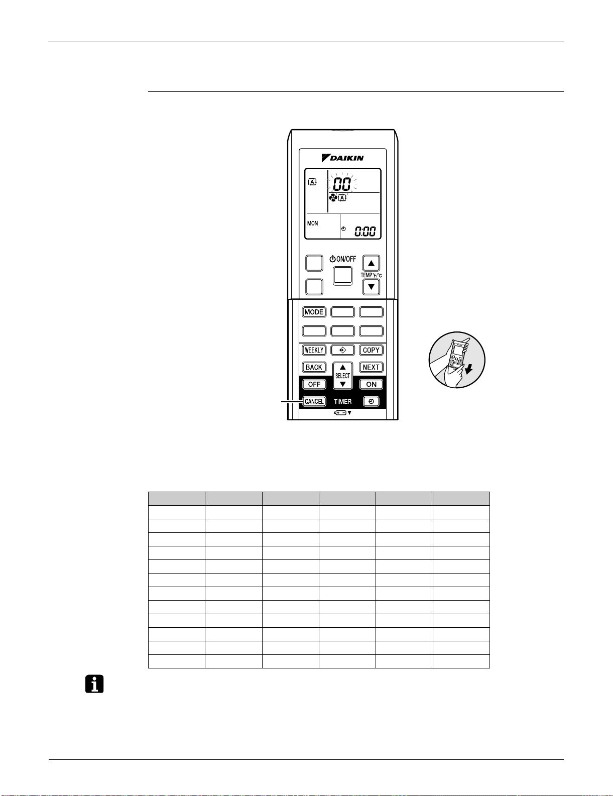
Service Check Function SiUS091133
91 Service Diagnosis
3. Service Check Function
Check Method 1 1. When the timer cancel button is held down for 5 seconds, 00 is displayed on the temperature
display screen.
2. Press the timer cancel button repeatedly until a long beep sounds.
The code indication changes in the sequence shown below.
Note: 1. A short beep or two consecutive beeps indicate non-corresponding codes.
2. To return to the normal mode, hold the timer cancel button down for 5 seconds. When the
remote controller is left untouched for 60 seconds, it also returns to the normal mode.
3. Not all the error codes are displayed. When you cannot find the error code, try the check
method 2. (Refer to page 92.)
No. Code No. Code No. Code
1 00 13 C7 25 UA
2 U4 14 A3 26 UH
3 L5 15 H8 27 P4
4 E6 16 H9 28 L3
5 H6 17 C9 29 L4
6 H0 18 C4 30 H7
7 A6 19 C5 31 U2
8 E7 20 J3 32 EA
9 U0 21 J6 33 AH
10 F3 22 E5 34 FA
11 A5 23 A1 35 H1
12 F6 24 E1 36 P9
(R14460)
Timer cancel button
< ARC452 Series >
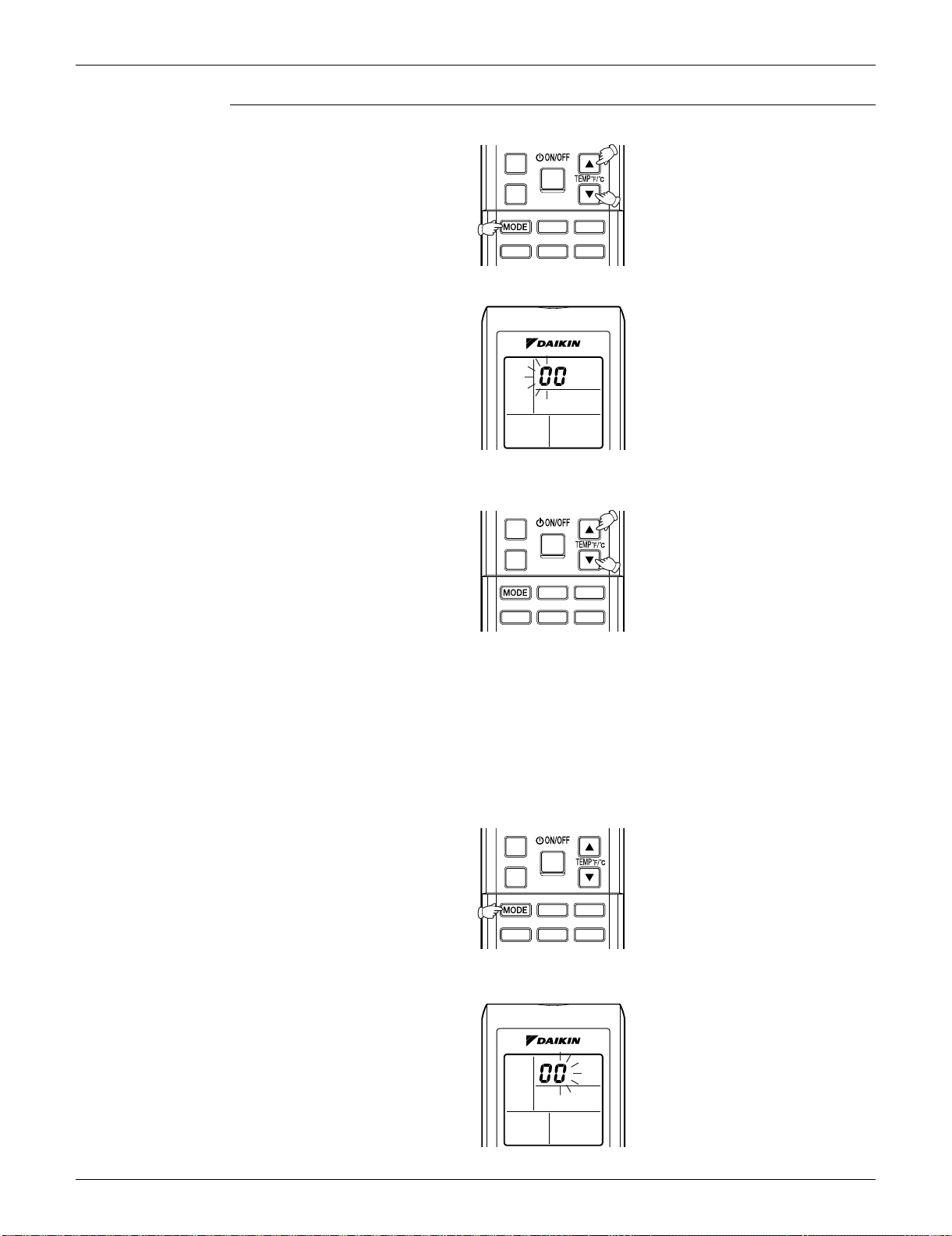
SiUS091133 Service Check Function
Service Diagnosis 92
Check Method 2 1. Press the 3 buttons (TEMP, TEMP, MODE) at the same time to enter the diagnosis mode.
The left-side number blinks.
2. Press the [TEMP]
or button and change the number until you hear the two consecutive
beeps or the long beep.
3. Diagnose by the sound.
beep : The left-side number does not correspond with the error code.
two consecutive beeps : The left-side number corresponds with the error code but the
right-side number does not.
long beep : Both the left-side and right-side number correspond with the error code.
The numbers indicated when you hear the long beep are the error code.
Refer to page 94.
4. Press the [MODE] button.
The right-side number blinks.
(R14550)
(R9430)
(R14551)
(R14552)
(R9429)
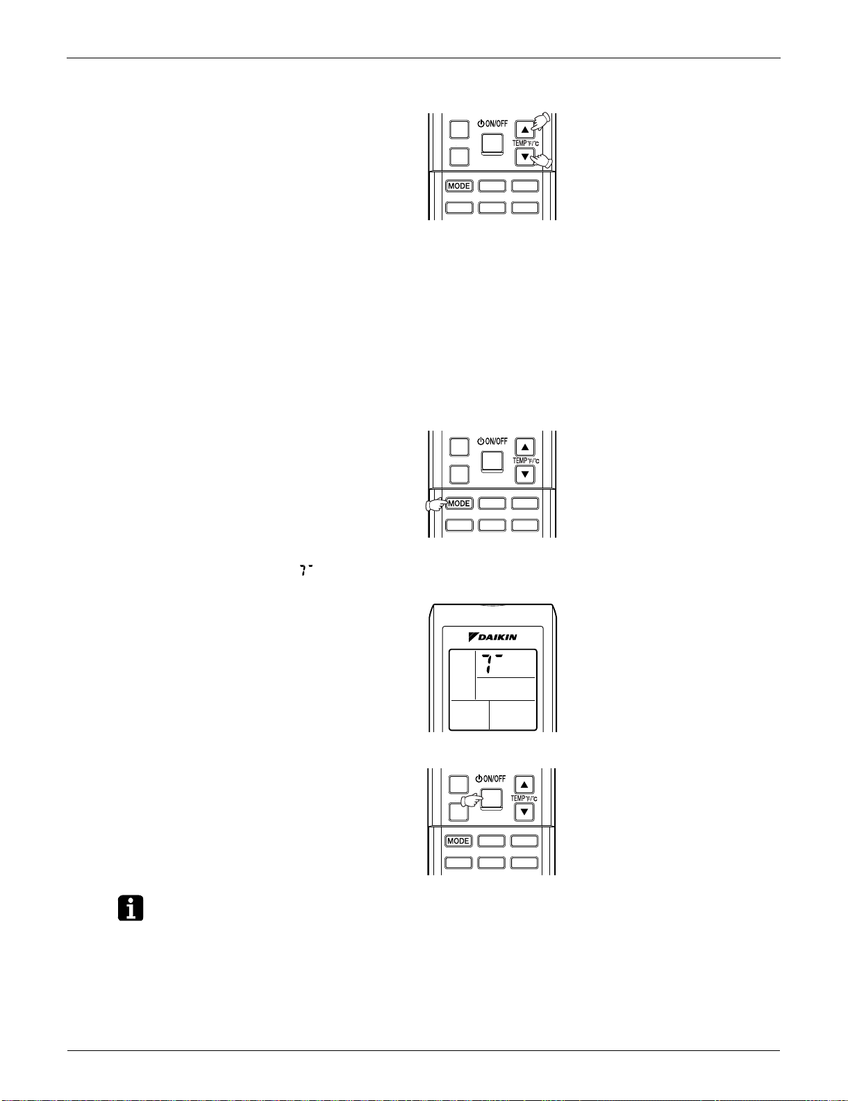
Service Check Function SiUS091133
93 Service Diagnosis
5. Press the [TEMP] or buttonand change the number until you hear the long beep.
6. Diagnose by the sound.
beep : The left-side number does not correspond with the error code.
two consecutive beeps : The left-side number corresponds with the error code but the
right-side number does not.
long beep : Both the left-side and right-side number corresponds with the error code.
7. Determine the error code.
The numbers indicated when you hear the long beep are the error code.
Error codes and description
Refer to page 94.
8. Press the [MODE] button to exit from the diagnosis mode.
The display means the trial operation mode.
Refer to page 386 for trial operation.
9. Press the [ON/OFF] button twice to return to the normal mode.
Note: When the remote controller is left untouched for 60 seconds, it returns to the normal mode.
(R14547)
(R14548)
(R9879)
(R14549)
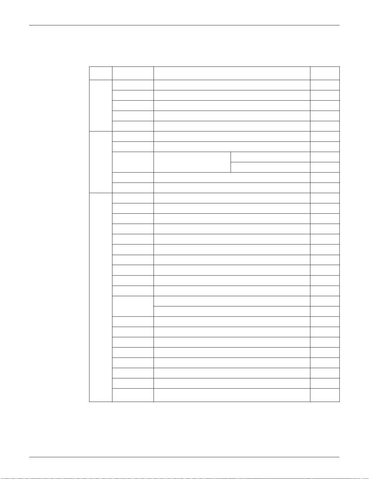
SiUS091133 Troubleshooting
Service Diagnosis 94
4. Troubleshooting
4.1 Error Codes and Description
: Displayed only when system-down occurs.
Error Codes Description
Reference
Page
System
00
Normal —
U0
Refrigerant shortage 104
U2
Low-voltage detection or over-voltage detection 107
U4
Signal transmission error (between indoor unit and outdoor unit) 109
UA
Unspecified voltage (between indoor unit and outdoor unit) 112
Indoor
Unit
A1
Indoor unit PCB abnormality 95
A5
Freeze-up protection control or heating peak-cut control 97
A6
Fan motor or related
abnormality
DC motor (FTXS series) 99
AC motor (FDXS series) 101
C4
Indoor heat exchanger thermistor or related abnormality 103
C9
Room temperature thermistor or related abnormality 103
Outdoor
Unit
E1
Outdoor unit PCB abnormality 113
E5
OL activation (compressor overload) 115
E6
Compressor lock 116
E7
DC fan lock 117
E8
Input overcurrent detection 118
EA
FourWay valve abnormality 119
F3
Discharge pipe temperature control 121
F6
High pressure control in cooling 123
H0
Compressor system sensor abnormality 125
H6
Position sensor abnormality 128
H8
DC voltage / current sensor abnormality (09/12 class only) 131
CT or related abnormality (24/30/36 class only) 132
H9
Outdoor temperature thermistor or related abnormality 134
J3
Discharge pipe thermistor or related abnormality 134
J6
Outdoor heat exchanger thermistor or related abnormality 134
L3
Electrical box temperature rise 136
L4
Radiation fin temperature rise 138
L5
Output overcurrent detection 140
P4
Radiation fin thermistor or related abnormality 134
U7
Signal transmission error on outdoor unit PCB
(24/30/36 class only)
111

Troubleshooting SiUS091133
95 Service Diagnosis
4.2 Indoor Unit PCB Abnormality
Remote
Controller
Display
A1
Method of
Malfunction
Detection
The system checks if the circuit works properly within the microcomputer of the indoor unit.
Malfunction
Decision
Conditions
The system cannot set the internal settings.
Supposed
Causes
Wrong models interconnected
Defective indoor unit PCB
Disconnection of connector
Reduction of power supply voltage
SiUS091133 Troubleshooting
Service Diagnosis 96
Troubleshooting
Note: Check the following connector.
Check the combination of the
indoor and outdoor unit.
OK?
Check the connection of
connectors (See Note.).
Correct the connection.
OK?
Check the power supply
voltage.
Start operation.
Voltage as rated?
Error repeats?
Check the power supply
voltage.
Start operation.
Voltage as rated?
Error repeats?
Error repeats?
YES
NO
NO
YES
NO
NO
YES
(R15270)
Caution
∗ To secure the connection,
once disconnect the connector
and then reconnect it.
YES
NO
YES
NO
YES
NO
YES
Match the compatible
models.
Correct the power
supply.
Replace the indoor unit
PCB (1).
Completed.
Completed.
Correct the power
supply.
Replace the indoor unit
PCB (1).
Completed.
Be sure to turn off the power switch before connecting or disconnecting
connectors, or parts may be damaged.
Model Type Connector
FTXS series Terminal board ~ Control PCB
FDXS series Terminal board ~ Control PCB

Troubleshooting SiUS091133
97 Service Diagnosis
4.3 Freeze-up Protection Control or Heating Peak-cut Control
Remote
Controller
Display
A5
Method of
Malfunction
Detection
Freeze-up protection control
During cooling operation, the freeze-up protection control (operation halt) is activated according
to the temperature detected by the indoor heat exchanger thermistor.
Heating peak-cut control
During heating operation, the temperature detected by the indoor heat exchanger thermistor is
used for the heating peak-cut control (operation halt, outdoor fan stop, etc.)
Malfunction
Decision
Conditions
Freeze-up protection control
During cooling operation, the indoor heat exchanger temperature is below 0°C (32°F).
Heating peak-cut control
During heating operation, the indoor heat exchanger temperature is above 60 ~ 65°C (140 ~
149°F) (depending on the model).
Supposed
Causes
Short-circuited air
Clogged air filter of the indoor unit
Dust accumulation on the indoor heat exchanger
Defective indoor heat exchanger thermistor
Defective indoor unit PCB
SiUS091133 Troubleshooting
Service Diagnosis 98
Troubleshooting
Check No.01
Refer to P.142
NO
NO
NO
Check No. 06
Check the indoor heat exchanger
thermistor.
YES
YES
(R7131)
YES
YES
NO
Caution
Provide sufficient air passage.
Clean the air filter.
Clean the indoor heat
exchanger.
Replace the indoor unit PCB.
Replace the thermistor.
Does it
conform to the
thermistor characteristic
chart?
Check the air filter.
Check the dust accumulation on
the indoor heat exchanger.
Is there any short circuit?
Is it very dirty?
Is it very dirty?
Check the air passage.
Be sure to turn off the power switch before connecting or disconnecting
connectors, or parts may be damaged.
NO
NO
NO
Check No. 01
Check the indoor heat exchanger
thermistor.
YES
YES
(R15715)
YES
YES
NO
Caution
Provide sufficient air passage.
Clean the air filter.
Clean the indoor heat
exchanger.
Replace the indoor unit PCB.
Replace the thermistor.
As
described in the
thermistor characteristic
chart?
Check the air filter.
Check the dust accumulation on
the indoor heat exchanger.
Is there any short circuit?
Dirty?
Dirty?
Check the air passage.
Be sure to turn off the power switch before connecting or disconnecting
connectors, or parts may be damaged.

Troubleshooting SiUS091133
99 Service Diagnosis
4.4 Fan Motor or Related Abnormality
4.4.1 DC Motor (FTXS Series)
Remote
Controller
Display
A6
Method of
Malfunction
Detection
The rotation speed detected by the Hall IC during fan motor operation is used to determine
abnormal fan motor operation.
Malfunction
Decision
Conditions
The detected rotation speed does not reach the demanded rotation speed of the target tap, and is
less than 50% of the maximum fan motor rotation speed.
Supposed
Causes
Layer short inside the fan motor winding
Breaking of wire inside the fan motor
Breaking of the fan motor lead wires
Defective capacitor of the fan motor
Defective indoor unit PCB
SiUS091133 Troubleshooting
Service Diagnosis 100
Troubleshooting
Check No.02
Refer to P.143
Turn off the power supply
and disconnect the fan
motor connector, then
turn the power on.
Check No.02
Check the output of the
fan motor connector
YES
YES
NO
YES
YES
NO
NO
NO
Note : The motor may break when the
motor connector is disconnected
while remaining power supply.
(Turn off the power supply before
connecting the connector also.)
Caution
Replace the indoor
fan motor.
Replace the indoor
unit PCB.
Replace the indoor
unit PCB.
Does the fan
rotate smoothly?
Does the fan
rotate?
Is the
motor power
supply voltage
310 ~ 340 VDC
generated?
Is the motor
control voltage 15
VDC generated?
Turn off the power supply
and rotate the fan by
hand.
Turn the power on and
start operation.
Be sure to turn off the power switch before connecting or disconnecting
connectors, or parts may be damaged.
Check No.02
Check the output of the
fan motor connector
(R14970)
NO
YES
YES
NO
YES
NO
Replace the indoor
fan motor.
Replace the indoor
unit PCB.
Replace the indoor
unit PCB.
Replace the indoor
fan motor.
Replace the indoor
fan motor and the
indoor unit PCB.
Is the rotation
pulse generated?
Is the
rotation
command voltage
1 ~ 5 VDC
generated?
Is the rotation
pulse generated?
Stop the fan motor.

Troubleshooting SiUS091133
101 Service Diagnosis
4.4.2 AC Motor (FDXS Series)
Remote
Controller
Display
A6
Method of
Malfunction
Detection
The rotation speed detected by the Hall IC during fan motor operation is used to determine
abnormal fan motor operation.
Malfunction
Decision
Conditions
The detected rotation speed does not reach the demanded rotation speed of the target tap, and is
less than 50% of the maximum fan motor rotation speed.
Supposed
Causes
Reduction of power supply voltage
Layer short inside the fan motor winding
Breaking of wire inside the fan motor
Breaking of the fan motor lead wires
Defective capacitor of the fan motor
Defective indoor unit PCB
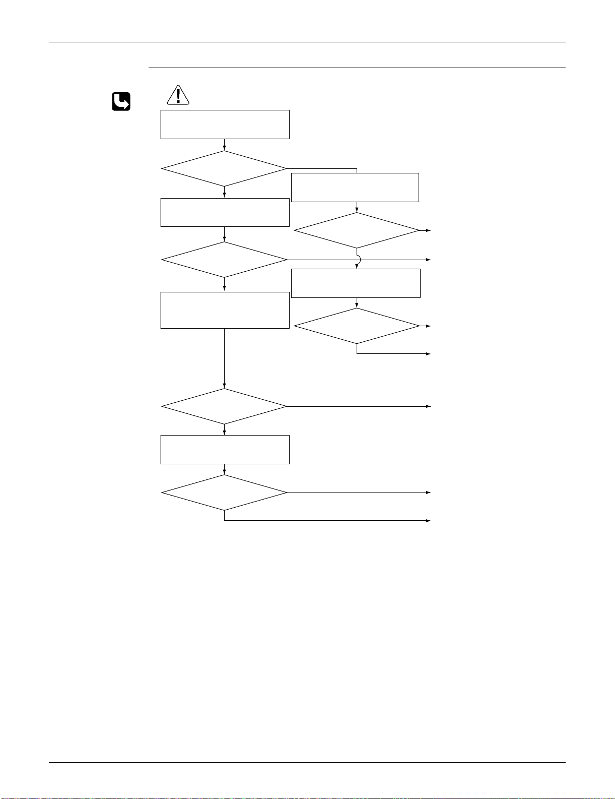
SiUS091133 Troubleshooting
Service Diagnosis 102
Troubleshooting
Check No.04
Refer to P.143
NO
NO
NO
NO
NO
NO
YES
YES
YES
YES
YES
YES
(R16009)
Caution
Replace the fan motor or the
indoor unit PCB.
Replace the fan motor.
Replace the indoor unit PCB.
Replace the capacitor.
(Replace the indoor unit PCB.)
Replace the fan motor.
Replace the fan motor.
Replace the indoor unit PCB.
Be sure to turn off the power switch before connecting or disconnecting
connectors, or parts may be damaged.
∗ Measure the voltage
between the red and black
lead wires of the fan motor,
and check if the maximum
voltage reaches the rated
voltage.
Check No. 04
Check Hall IC
Is there an output?
Check the fan motor voltage.
Voltage as rated? ∗
Start operation.
Does the fan rotate?
Turn off the power supply and
rotate the fan by hand.
Does the fan rotate
smoothly?
Turn the power on and check the
fan motor voltage. (immediately
after restart)
Voltage as rated? ∗
Check the capacitor's continuity.
Is there continuity?
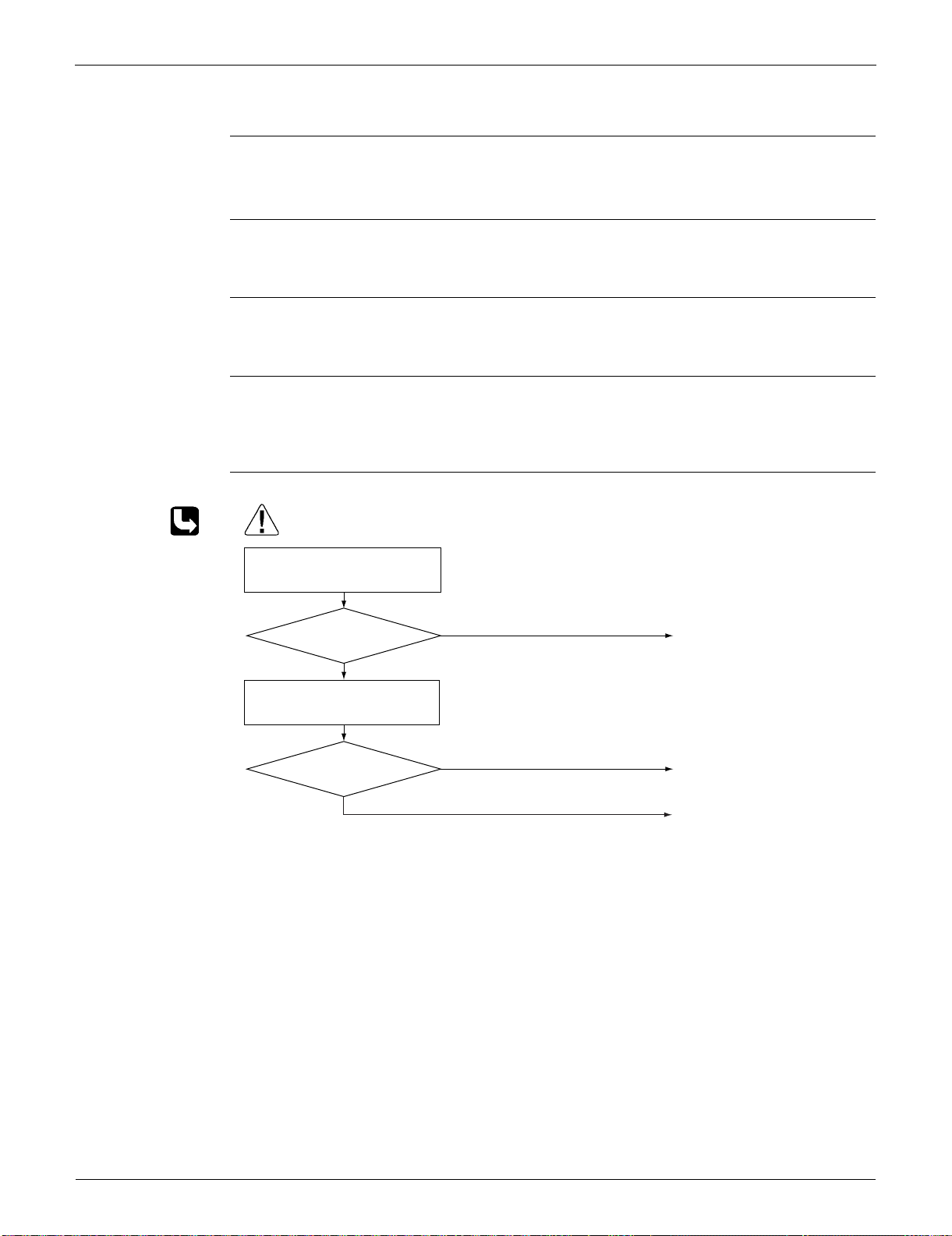
Troubleshooting SiUS091133
103 Service Diagnosis
4.5 Thermistor or Related Abnormality (Indoor Unit)
Remote
Controller
Display
C4, C9
Method of
Malfunction
Detection
The temperatures detected by the thermistors determine thermistor errors.
Malfunction
Decision
Conditions
The thermistor input is more than 4.96 V or less than 0.04 V during compressor operation.
Supposed
Causes
Disconnection of connector
Defective thermistor
Defective indoor unit PCB
Troubleshooting
Check No.01
Refer to P.142
C4 : Indoor heat exchanger thermistor
C9 : Room temperature thermistor
YES
(R15717)
NO
Check No. 01
Check the thermistor resistance
value.
YES
NO
Caution
Correct the connection.
Replace the thermistor.
Replace the indoor unit PCB.
Normal?
Normal?
Check the connection of
connectors.
Be sure to turn off the power switch before connecting or disconnecting
connectors, or parts may be damaged.
SiUS091133 Troubleshooting
Service Diagnosis 104
4.6 Refrigerant Shortage
Remote
Controller
Display
U0
Method of
Malfunction
Detection
Refrigerant shortage detection I:
Refrigerant shortage is detected by checking the input current value and the compressor running
frequency. If the refrigerant is short, the input current is lower than the normal value.
Refrigerant shortage detection II:
Refrigerant shortage is detected by checking the discharge pipe temperature and the opening of
the electronic expansion valve. If the refrigerant is short, the discharge pipe temperature tends to
rise.
Refrigerant shortage detection III:
Refrigerant shortage is detected by checking the difference between suction and discharge
temperature.
Malfunction
Decision
Conditions
Refrigerant shortage detection I:
The following conditions continue for 7 minutes.
<09/12 class>
Input current × input voltage
A × output frequency + B
Output frequency > C
<15/18/24/30/36 class>
Input current
D × output frequency + E
Output frequency > F
Refrigerant shortage detection II:
The following conditions continue for 80 seconds.
Opening of the electronic expansion valve G
Discharge pipe temperature (°C) > H × target discharge pipe temperature (°C) + J (°C)
(Discharge pipe temperature (°F) > H × target discharge pipe temperature (°F) + K (°F))
A
(–)
B (W) C (Hz)
09/12 class 640/256 0 55
D (–) E (A) F (Hz)
15/18 class 2000/256 –181 55
24/30/36 class 27/1000 2.0 40
G (pulse) H (–) J (°C) K (°F)
09/12 class 480 128/128 cooling: 63.5, heating: 30 cooling: 114.3, heating: 54
15/18 class 480 128/128 cooling: 60, heating: 45 cooling: 108, heating: 81
24 class 450 128/128 60 108
30/36 class 480 128/128 cooling: 50, heating: 45 cooling: 90, heating: 81

Troubleshooting SiUS091133
105 Service Diagnosis
Refrigerant shortage detection III: (09/12 class only)
When the difference of the temperature is smaller than L, it is regarded as refrigerant shortage.
If the error repeats, the system is shut down.
Reset condition: Continuous run for about 60 minutes without any other error
Supposed
Causes
Disconnection of the discharge pipe thermistor, indoor or outdoor heat exchanger thermistor,
room or outdoor temperature thermistor
Closed stop valve
Refrigerant shortage (refrigerant leakage)
Poor compression performance of compressor
Defective electronic expansion valve
L
Cooling
room thermistor temperature – indoor heat exchanger temperature 4.0°C (7.2°F)
outdoor heat exchanger temperature – outdoor temperature 4.0°C (7.2°F)
Heating
indoor heat exchanger temperature – room thermistor temperature 3.0°C (5.4°F)
outdoor temperature – outdoor heat exchanger temperature 3.0°C (5.4°F)

SiUS091133 Troubleshooting
Service Diagnosis 106
Troubleshooting
Check No.01
Refer to P.142
Check No.12
Refer to P.144
(R16015)
Caution
YES
NG
NO
NO
YES
YES
YES
NO
YES
NO
NO
YES
NO
NO
YES
∗ Discharge pipe thermistor
∗ Indoor or outdoor heat exchanger thermistor
∗ Room temperature thermistor
∗ Outdoor temperature thermistor
Check for refrigerant shortage.
Change for a specified amount of
fresh refrigerant.
Check No. 12
Electronic expansion valve
functioning?
Replace the thermistor(s) in
position.
Open the stop valve.
Repair the pipe flare or
replace the union.
Check the power transistor
harness for loosening.
Correct it as required. Also
replace the cracked pipe.
Check the pipes for
improper contact and
correct them as required.
Replace the cracked pipe.
Replace the electronic
expansion valve.
Replace the defective
thermistor(s).
Completed.
Refrigerant shortage error
again?
Oil oozing at internal
piping?
Stop valve closed?
Compressor vibrating
too much?
Oil oozing at relay
pipe connections?
Any thermistor
disconnected?
Check No. 01
Check the thermistors.
Be sure to turn off the power switch before connecting or disconnecting
connectors, or parts may be damaged.
OK
NO
YES
Replace the outdoor unit PCB.
Replace the compressor.
Completed.
Error again?

Troubleshooting SiUS091133
107 Service Diagnosis
4.7 Low-voltage Detection or Over-voltage Detection
Remote
Controller
Display
U2
Method of
Malfunction
Detection
Indoor Unit
The zero-cross detection of the power supply is evaluated by the indoor unit PCB.
Outdoor Unit
Low-voltage detection:
An abnormal voltage drop is detected by the DC voltage detection circuit.
Over-voltage detection:
An abnormal voltage rise is detected by the over-voltage detection circuit.
Malfunction
Decision
Conditions
Indoor Unit
There is no zero-cross detection in approximately 10 seconds.
Outdoor Unit
Low-voltage detection:
The voltage detected by the DC voltage detection circuit is below 150 ~ 200 V (depending on
the model).
The compressor stops if the error occurs, and restarts automatically after 3-minute standby.
Over-voltage detection:
An over-voltage signal is fed from the over-voltage detection circuit to the microcomputer.
The compressor stops if the error occurs, and restarts automatically after 3-minute standby.
Supposed
Causes
Supply voltage is not as specified.
Defective DC voltage detection circuit
Defective over-voltage detection circuit
Defective PAM control part
Disconnection of compressor harness
Noise
Momentary fall of voltage
Momentary power failure
Defective indoor unit PCB
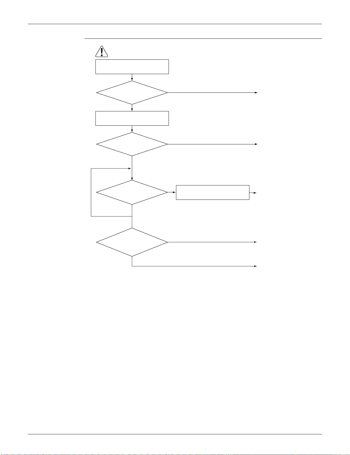
SiUS091133 Troubleshooting
Service Diagnosis 108
Troubleshooting
Correct the power supply.
Replace the outdoor
unit PCB.
Check for such factors for a
long term.
∗ Try to restart a few times.
(R16043)
Caution
Be sure to turn off the power switch before connecting or disconnecting
connectors, or parts may be damaged.
NO
NO
YES
NO
YES
YES
Reconnect the harness.
Check the power supply voltage.
Check the connection of the
compressor harness.
Disturbance factors
∗ Noise ∗ Power supply distortion
Repeat a few
times.
(Precaution before turning on the power again)
Make sure the power has been off for at
least 30 seconds.
Replace the indoor
unit PCB.
Turn on the
power again. System
restarted?
Error
again within 3 minutes
after turning on the
power?
Loose or
disconnected?
Voltage as rated?
YES
NO

Troubleshooting SiUS091133
109 Service Diagnosis
4.8 Signal Transmission Error (between Indoor Unit and
Outdoor Unit)
Remote
Controller
Display
U4
Method of
Malfunction
Detection
The data received from the outdoor unit in indoor unit-outdoor unit signal transmission is checked
whether it is normal.
Malfunction
Decision
Conditions
The data sent from the outdoor unit cannot be received normally, or the content of the data is
abnormal.
Supposed
Causes
Wiring error
Breaking of the connection wires between the indoor and outdoor units (wire No. 3)
Defective outdoor unit PCB
Defective indoor unit PCB
Disturbed power supply waveform
SiUS091133 Troubleshooting
Service Diagnosis 110
Troubleshooting
Check No.11
Refer to P.144
Check No.11
Check the power supply
waveform.
Check the voltage of the
connection wires on the indoor
terminal board between No. 1
and No. 3, and between No. 2
and No. 3.
YES
YES
Replace the indoor unit PCB.
Locate the cause of the
disturbance of the power supply
waveform, and correct it.
NO
(R16914)
NO
YES
YES
NO
NO
Caution
Correct the indoor unit - outdoor
unit connection wires.
Diagnose the outdoor unit
PCB.
∗ Before you check the LED A,
cancel the standby electricity
saving function by starting fan
operation with the remote
controller.
∗ Wait at least for 7 sec. after
turning on the power.
Replace the connection wires
between the indoor unit and
the outdoor unit.
Is LED A blinking?
Properly insulated?
Is there any disturbance?
Is there any wiring error?
Check the indoor unit - outdoor
unit connection wires.
Check the LED A on the outdoor
unit PCB.
Be sure to turn off the power switch before connecting or disconnecting
connectors, or parts may be damaged.
Troubleshooting SiUS091133
111 Service Diagnosis
4.9 Signal Transmission Error on Outdoor Unit PCB
(24/30/36 Class Only)
Remote
Controller
Display
U7
Method of
Malfunction
Detection
Communication error between microcomputer mounted on the main microcomputer and PM1.
Malfunction
Decision
Conditions
The abnormality is determined when the data sent from the PM1 can not be received for 9
seconds.
The error counter is reset when the data from the PM1 can be successfully received.
Supposed
Causes
Defective outdoor unit PCB
Troubleshooting
(R7185)
Caution
NO
YES
Turn off the power and turn it on
again.
Error again?
Replace the outdoor unit
PCB.
Be sure to turn off the power switch before connecting or disconnecting
connectors, or parts may be damaged.
The cause can be an
external factor other than
the malfunction.
Observe the operating
condition in long term.
SiUS091133 Troubleshooting
Service Diagnosis 112
4.10 Unspecified Voltage (between Indoor Unit and Outdoor
Unit)
Remote
Controller
Display
UA
Method of
Malfunction
Detection
The supply power is detected for its requirements (different from pair type and multi type) by the
indoor / outdoor transmission signal.
Malfunction
Decision
Conditions
The pair type and multi type are interconnected.
Supposed
Causes
Wrong models interconnected
Wrong wiring of connecting wires
Wrong indoor unit PCB or outdoor unit PCB mounted
Defective indoor unit PCB
Defective outdoor unit PCB
Troubleshooting
(R11707)
Caution
NO
YES
YES
YES
NO
NO
Check the code numbers
(2P01234, for example) of the
indoor and outdoor unit PCB with
the Parts List.
Match the compatible models.
Change for the correct PCB.
Replace the indoor unit PCB
(or the outdoor unit PCB).
OK?
Matched compatibly?
Correct the connection.
Are the
connection wires connected
property?
Check the combination of the
indoor and outdoor unit.
Be sure to turn off the power switch before connecting or disconnecting
connectors, or parts may be damaged.
Troubleshooting SiUS091133
113 Service Diagnosis
4.11 Outdoor Unit PCB Abnormality
Remote
Controller
Display
E1
Method of
Malfunction
Detection
The system checks if the microprocessor is working in order.
The system checks if the zero-cross signal comes in properly.
Malfunction
Decision
Conditions
The microprocessor program runs out of control.
The zero-cross signal is not detected.
Supposed
Causes
Defective outdoor unit PCB
Broken harness between PCBs
Noise
Momentary fall of voltage
Momentary power failure, etc.
Troubleshooting 09/12/15/18 class
Caution
Be sure to turn off the power switch before connecting or disconnecting
connectors, or parts may be damaged.
NO
YES
YES
(R16910)
YES
NO
NO
Replace the outdoor unit
PCB (2).
Ground the system.
Zero-cross signal
abnormality.
Replace the outdoor unit
PCB (1).
Replace the harness.
Check to see if the outdoor unit is
grounded.
Is LED A blinking?
Grounded?
Is the harness
broken?
Turn on the power again.
∗ Before you check the LED A,
cancel the standby electricity
saving function by starting fan
operation with the remote
controller.
∗ Wait at least for 7 sec. after
turning on the power.
SiUS091133 Troubleshooting
Service Diagnosis 114
Troubleshooting 24/30/36 class
(R16911)
Caution
Be sure to turn off the power switch before connecting or disconnecting
connectors, or parts may be damaged.
YES
NO
NO
YES
Turn on the power again.
Check to see if the unit is
grounded.
Replace the outdoor unit
PCB.
Ground the system.
The cause can be external
factors other than
malfunction.
Investigate the cause of
noise.
Error again?
Grounded?
∗ Before you check the LED A,
cancel the standby electricity
saving function by starting fan
operation with the remote
controller.
∗ Wait at least for 7 sec. after
turning on the power.
Troubleshooting SiUS091133
115 Service Diagnosis
4.12 OL Activation (Compressor Overload)
Remote
Controller
Display
E5
Method of
Malfunction
Detection
A compressor overload is detected through compressor OL.
Malfunction
Decision
Conditions
If the error repeats, the system is shut down.
Reset condition: Continuous run for about 60 minutes without any other error
The operating temperature condition is not specified.
Supposed
Causes
Defective discharge pipe thermistor
Defective electronic expansion valve or coil
Defective FourWay valve or coil
Defective outdoor unit PCB
Refrigerant shortage
Water mixed in refrigerant
Defective stop valve
Troubleshooting
Check No.01
Refer to P.142
Check No.12
Refer to P.144
Check No.13
Refer to P.145
Check No.14
Refer to P.145
(R14438)
Caution
YES
NG
* Discharge pipe thermistor
NO
OK
OK
NG
NG
OK
NG
OK
* Refrigerant shortage
* Water mixed
* Stop valve
Insert the thermistor in
position.
Replace the discharge pipe
thermistor.
Replace the electronic
expansion valve or the coil.
Refer to the refrigerant line
check procedure.
Replace the outdoor unit
PCB.
Replace the four-way valve
or the coil.
Replace the outdoor unit
PCB.
Discharge pipe
thermistor disconnected?
Check No. 01
Check the thermistors.
Check No. 13
Check the four-way valve.
Check No. 14
Check the refrigerant line.
Check No. 12
Check the electronic
expansion valve.
Be sure to turn off the power switch before connecting or disconnecting
connectors, or parts may be damaged.
SiUS091133 Troubleshooting
Service Diagnosis 116
4.13 Compressor Lock
Remote
Controller
Display
E6
Method of
Malfunction
Detection
A compressor lock is detected by checking the compressor running condition through the position
detection circuit.
Malfunction
Decision
Conditions
09/12 class
Operation stops due to overcurrent.
If the error repeats, the system is shut down.
Reset condition: Continuous run for about 11 minutes without any other error
15/18/24/30/36 class
A compressor lock is detected by the current waveform generated when applying high-
frequency voltage to the motor.
If the error repeats, the system is shut down
Reset condition: Continuous run for about 5 minutes without any other error
Supposed
Causes
Compressor locked
Compressor harness disconnected
Troubleshooting
Check No.15
Refer to P.146
Turn off the power. Disconnect the
harnesses U, V, and W.
(R14439)
Caution
NO
YES
YES
NO
NO
YES
Check No.15
Check with the inverter checker (∗).
Turn off the power and reconnect
the harnesses. Turn on the power
again and restart the system.
(Precaution before turning on the power again)
Make sure the power has been off for at least 30 seconds.
Correct the power supply or
replace the outdoor unit
PCB.
∗ Inverter checker
Part No.: 1225477
Replace the compressor.
Replace the compressor.
Check the outdoor electronic
expansion valve coil.
Replace it as required.
Normal?
Emergency
stop without compressor
running?
System shut
down after errors repeated
several times?
Be sure to turn off the power switch before connecting or disconnecting
connectors, or parts may be damaged.
Troubleshooting SiUS091133
117 Service Diagnosis
4.14 DC Fan Lock
Remote
Controller
Display
E7
Method of
Malfunction
Detection
An error is determined with the high-voltage fan motor rotation speed detected by the Hall IC.
Malfunction
Decision
Conditions
The fan does not start in 15 ~ 30 seconds (depending on the model) even when the fan motor is
running.
If the error repeats, the system is shut down.
Reset condition: Continuous run for about 11 minutes (09/12 class) or 5 minutes (15/18/24/30/
36 class) without any other error
Supposed
Causes
Foreign matter stuck in the fan
Defective fan motor
Defective outdoor unit PCB
Troubleshooting
Check No.16
Refer to P.148
(R15675)
Caution
YES
YES
NO
YES
NO
NO
YES
NO
Turn on the power.
Rotate the fan.
Check No. 16
Check the rotation pulse input on
the outdoor unit PCB.
Turn off the power and
reconnect the connector.
Remove the foreign
matters.
Replace the outdoor fan
motor.
Replace the outdoor unit
PCB.
Fan motor connector
disconnected?
Foreign matters in or
around the fan?
Replace the outdoor fan
motor.
Fan rotates
smoothly?
Pulse signal generated?
Be sure to turn off the power switch before connecting or disconnecting
connectors, or parts may be damaged.
SiUS091133 Troubleshooting
Service Diagnosis 118
4.15 Input Overcurrent Detection
Remote
Controller
Display
E8
Method of
Malfunction
Detection
An input overcurrent is detected by checking the input current value with the compressor running.
Malfunction
Decision
Conditions
The current exceeds about 9.25 ~ 20 A for 2.5 seconds with the compressor running.
(The upper limit of the current decreases when the outdoor temperature exceeds a certain
level.)
Supposed
Causes
Outdoor temperature is out of operation range.
Defective compressor
Defective power module
Defective outdoor unit PCB
Short circuit
Troubleshooting
Check No.15
Refer to P.146
Check No.17
Refer to P.149
Check No.18
Refer to P.150
Caution
Be sure to turn off the power switch before connecting or disconnecting
connectors, or parts may be damaged.
∗ An input overcurrent may result from wrong internal wiring. If the system is interrupted by an input
overcurrent after the wires have been disconnected and reconnected for part replacement, check the
wiring again.
(R14440)
NO
YES
YES
NO
Start operation and measure the
input current.
Check No. 18
Check the discharge pressure.
Check No. 17
Check the installation condition.
Check No.15
Check with the inverter checker (∗).
Turn off the power and disconnect
the harnesses U, V, and W.
Turn off the power, and reconnect
the harnesses. Turn on the power
again and start operation.
Replace the outdoor unit
PCB.
Correct the power supply or
replace the outdoor unit
PCB.
Any LED off?
Input current flowing
above its stop level?
∗ Inverter checker
Part No.: 1225477

Troubleshooting SiUS091133
119 Service Diagnosis
4.16 FourWay Valve Abnormality
Remote
Controller
Display
EA
Method of
Malfunction
Detection
The room temperature thermistor and the indoor heat exchanger thermistor are checked if they
function within their normal ranges in each operation mode.
Malfunction
Decision
Conditions
A following condition continues over 1 ~ 10 minutes after operating for 5 ~ 10 minutes.
Cooling / Dry
(room thermistor temp. – indoor heat exchanger temp.) < –5°C (–9°F)
Heating
(indoor heat exchanger temp. – room thermistor temp.) < –5°C (–9°F)
If the error repeats, the system is shut down.
Reset condition: Continuous run for about 60 minutes without any other error
Supposed
Causes
Disconnection of fourway valve coil
Defective fourway valve, coil, or harness
Defective outdoor unit PCB
Defective thermistor
Refrigerant shortage
Water mixed in refrigerant
Defective stop valve
SiUS091133 Troubleshooting
Service Diagnosis 120
Troubleshooting
Check No.01
Refer to P.142
Check No.13
Refer to P.145
Check No.14
Refer to P.145
NG
OK
NO
OK
NG
OK
YES
NG
Correct the four-way valve
coil.
Reconnect the harness.
YES
YES
YES
NO
NO
Replace the outdoor
unit PCB.
Replace the defective
thermistor(s).
Refer to the refrigerant line
check procedure.
Replace the four-way valve
(defective or dust-clogged).
Reconnect the
thermistor(s).
Caution
Be sure to turn off the power switch before connecting or disconnecting
connectors, or parts may be damaged.
(R15824)
* Refrigerant shortage
* Water mixed
* Stop valve
Four-way valve
coil disconnected (loose)?
Harness out of
connector?
Any thermistor
disconnected?
Check No. 01
Check the thermistors.
Check No. 14
Check the refrigerant line.
Check No.
13
Check the four-way valve
switching output.
Check the continuity of the four-way
valve coil and harness.
Replace the four-way
valve coil.
NO
Resistance
between harnesses
about 1000 ~ 2000 W?
Disconnect the harness from the
connector.
Troubleshooting SiUS091133
121 Service Diagnosis
4.17 Discharge Pipe Temperature Control
Remote
Controller
Display
F3
Method of
Malfunction
Detection
An error is determined with the temperature detected by the discharge pipe thermistor.
Malfunction
Decision
Conditions
If the temperature detected by the discharge pipe thermistor rises above A, the compressor
stops.
The error is cleared when the discharge pipe temperature has dropped below B.
<09/12 class>
<15/18/24/30/36 class>
If the error repeats, the system is shut down.
Reset condition: Continuous run for about 60 minutes without any other error
Supposed
Causes
Defective discharge pipe thermistor
(Defective outdoor heat exchanger thermistor or outdoor temperature thermistor)
Defective electronic expansion valve or coil
Refrigerant shortage
Defective fourway valve
Water mixed in refrigerant
Defective stop valve
Defective outdoor unit PCB
AB
(1) above 45 Hz (rising), above 40 Hz (dropping) 110°C (230°F) 97°C (206.6°F)
(2) 30 ~ 45 Hz (rising), 25 ~ 40 Hz (dropping) 105°C (221°F) 92°C (197.6°F)
(3) below 30 Hz (rising), below 25 Hz (dropping) 99°C (210.2°F) 86°C (186.8°F)
AB
15/18 class 110°C (230°F) 95°C (203°F)
24/30/36 class 120°C (248°F) 107°C (224.6°F)
SiUS091133 Troubleshooting
Service Diagnosis 122
Troubleshooting
Check No.01
Refer to P.142
Check No.12
Refer to P.144
Check No.14
Refer to P.145
(R15825)
Caution
NG
OK
OK
OK
NG
NG
* Discharge pipe thermistor
* Outdoor heat exchanger thermistor
* Outdoor temperature thermistor
* Refrigerant shortage
* Four-way valve
* Water mixed
* Stop valve
Check No. 01
Check the thermistors.
Check No. 14
Check the refrigerant line.
Check No. 12
Check the electronic
expansion valve.
Replace the defective
thermistor(s).
Replace the electronic
expansion valve or the coil.
Refer to the refrigerant line
check procedure.
Replace the outdoor unit
PCB.
Be sure to turn off the power switch before connecting or disconnecting
connectors, or parts may be damaged.

Troubleshooting SiUS091133
123 Service Diagnosis
4.18 High Pressure Control in Cooling
Remote
Controller
Display
F6
Method of
Malfunction
Detection
High-pressure control (operation halt, frequency drop, etc.) is activated in cooling operation if the
temperature sensed by the outdoor heat exchanger thermistor exceeds the limit.
Malfunction
Decision
Conditions
The temperature sensed by the outdoor heat exchanger thermistor rises above about 60 ~ 65°C
(140 ~ 149°F).
The error is cleared when the temperature drops below about 50°C (122°F).
Supposed
Causes
The installation space is not large enough.
Dirty outdoor heat exchanger
Defective outdoor fan motor
Defective stop valve
Defective electronic expansion valve or coil
Defective outdoor heat exchanger thermistor
Defective outdoor unit PCB
SiUS091133 Troubleshooting
Service Diagnosis 124
Troubleshooting
Check No.01
Refer to P.142
Check No.12
Refer to P.144
Check No.17
Refer to P.149
Check No.18
Refer to P.150
Check No.19
Refer to P.150
(R15667)
Caution
Replace the outdoor fan
motor.
Reconnect the connector or
fan motor lead wires.
Replace the stop valve.
Replace the outdoor heat
exchanger thermistor.
Replace the outdoor unit
PCB.
Replace the electronic
expansion valve or the coil.
Replace the outdoor unit
PCB.
Change the installation
location or direction.
Clean the outdoor heat
exchanger.
Check the installation space.
NG
OK
OK
NG
NG
OK
OK
OK
NG
NG
Check No. 19
Check the outdoor fan.
Check No. 18
Check the discharge
pressure.
Check No. 12
Check the electronic
expansion valve.
Check No. 01
Check the outdoor heat
exchanger thermistor.
Check No. 17
Check the installation
condition.
Be sure to turn off the power switch before connecting or disconnecting
connectors, or parts may be damaged.
Troubleshooting SiUS091133
125 Service Diagnosis
4.19 Compressor System Sensor Abnormality
4.19.1 09/12/15/18 Class
Remote
Controller
Display
H0
Method of
Malfunction
Detection
The system checks the DC current before the compressor starts.
Malfunction
Decision
Conditions
The DC current before compressor start-up is out of the range 0.5 ~ 4.5 V (sensor output
converted to voltage value)
The DC voltage before compressor start-up is below 50 V.
Supposed
Causes
Broken or disconnected harness
Defective outdoor unit PCB
Troubleshooting
Caution
Be sure to turn off the power switch before connecting or disconnecting
connectors, or parts may be damaged.
NO
(R11712)
YES
Turn off the power and turn it on
again.
YES
NO
Replace the harness.
Replace the outdoor unit
PCB.
Is the harness broken?
Restart operation
and error displayed
again?
Check the relay harness for the
compressor.
No problem.
Keep on running.

SiUS091133 Troubleshooting
Service Diagnosis 126
4.19.2 24/30/36 Class
Remote
Controller
Display
H0
Method of
Malfunction
Detection
The system checks the supply voltage and the DC voltage before the compressor starts.
The system checks the compressor current right after the compressor starts.
Malfunction
Decision
Conditions
The supply voltage and the DC voltage is obviously low or high.
The compressor current does not run when the compressor starts.
Supposed
Causes
Disconnection of reactor
Disconnection of compressor harness
Defective outdoor unit PCB
Defective compressor
Troubleshooting SiUS091133
127 Service Diagnosis
Troubleshooting
Connect the reactor
properly.
(R15891)
NO
YES
Connect the compressor
properly.
NO
YES
Replace the reactor.
NO
YES
Replace the compressor or
the compressor relay
harness.
Restart the operation again
and if the error occurs
again, replace the outdoor
unit PCB.
NO
YES
Disconnect the reactor from the outdoor
unit PCB and measure the resistance
value between reactor terminals with
tester.
Disconnect the compressor relay harness
from the outdoor unit PCB and measure
the resistance value between the each 3
terminals of the compressor with tester.
Caution
Be sure to turn off the power switch before connecting or disconnecting
connectors, or parts may be damaged.
10 Ω or less
between each terminal?
Check the connection of the
compressor.
Check the reactor.
Check the compressor.
Turn off the power.
Check the connection of the
reactor.
Connection OK?
Connection OK?
10 Ω or less?

SiUS091133 Troubleshooting
Service Diagnosis 128
4.20 Position Sensor Abnormality
Remote
Controller
Display
H6
Method of
Malfunction
Detection
A compressor start-up failure is detected by checking the compressor running condition through the
position detection circuit.
Malfunction
Decision
Conditions
If the error repeats, the system is shut down.
Reset condition: Continuous run for about 11 minutes (09/12 class) or 5 minutes (15/18/24/30/
36 class) without any other error
Supposed
Causes
Disconnection of the compressor relay cable
Defective compressor
Defective outdoor unit PCB
Start-up failure caused by the closed stop valve
Input voltage is outside the specified range.
Troubleshooting SiUS091133
129 Service Diagnosis
Troubleshooting 09/12/15/18 class
Check No.15
Refer to P.146
Check No.18
Refer to P.150
Check No.20
Refer to P.151
Caution
Be sure to turn off the power switch before connecting or disconnecting
connectors, or parts may be damaged.
NO
YES
Turn off the power.
Check the connection.
Check the power supply voltage.
Correct the power supply.
Voltage as rated?
(R15827)
NO
NO
NO
YES
YES
NO
YES
YES
Check No. 20
Check the short circuit of the diode
bridge.
Check No.15
Check with the inverter checker (∗).
Turn off the power. Disconnect the
harnesses U, V, and W.
Turn on the power.
Check the electrolytic capacitor
voltage.
Electrical
components or
compressor harnesses
connected as
specified?
Replace the outdoor unit
PCB.
Replace the compressor.
Correct the power supply
or replace the outdoor unit
PCB.
Reconnect the electrical
components or compressor
harnesses as specified.
Replace the outdoor unit
PCB.
∗ Inverter checker
Part No.: 1225477
Normal?
NO
YES
Check No. 18
Check the discharge pressure.
Replace the stop valve.
OK?
320 ± 50 VDC?
Any LED OFF?
SiUS091133 Troubleshooting
Service Diagnosis 130
Troubleshooting 24/30/36 class
Check No.15
Refer to P.146
Check No.18
Refer to P.150
Caution
Be sure to turn off the power switch before connecting or disconnecting
connectors, or parts may be damaged.
NO
YES
Check the power supply voltage.
Check the connection.
Turn off the power.
Correct the power supply.
Voltage as rated?
(R15892)
NO
NO
YES
NO
YES
YES
Check No. 15
Check with the inverter checker (∗).
Turn off the power. Disconnect the
harnesses U, V, and W.
Turn on the power.
Check the electrolytic capacitor
voltage.
Electrical
components or
compressor harnesses
connected as
specified?
Replace the outdoor unit
PCB.
Replace the compressor.
Correct the power supply or
replace the outdoor unit
PCB.
Reconnect the electrical
components or compressor
harnesses as specified.
∗ Inverter checker
Part No.: 1225477
320 ± 50 VDC?
Any LED OFF?
NO
YES
Check No. 18
Check the discharge pressure.
Replace the stop valve.
OK?
Troubleshooting SiUS091133
131 Service Diagnosis
4.21 DC Voltage / Current Sensor Abnormality (09/12 Class Only)
Remote
Controller
Display
H8
Method of
Malfunction
Detection
DC voltage or DC current sensor abnormality is identified based on the compressor running
frequency and the input current.
Malfunction
Decision
Conditions
If the error repeats, the system is shut down.
Reset condition: Continuous run for about 60 minutes without any other error
Supposed
Causes
Defective outdoor unit PCB
Troubleshooting
Replace the outdoor unit PCB.
Caution
Be sure to turn off the power switch before connecting or disconnecting
connectors, or parts may be damaged.
SiUS091133 Troubleshooting
Service Diagnosis 132
4.22 CT or Related Abnormality (24/30/36 Class Only)
Remote
Controller
Display
H8
Method of
Malfunction
Detection
A CT or related error is detected by checking the compressor running frequency and CT-detected
input current.
Malfunction
Decision
Conditions
The compressor running frequency is more than A Hz, and the CT input current is less than B
A.
If the error repeats, the system is shut down.
Reset condition: Continuous run for about 60 minutes without any other error
Supposed
Causes
Defective power module
Broken or disconnected wiring
Defective reactor
Defective outdoor unit PCB
A (Hz) B (A)
32 0.5
Troubleshooting SiUS091133
133 Service Diagnosis
Troubleshooting
Check No.15
Refer to P.146
Check No.21
Refer to P.152
(R15326)
Caution
YES
2 sec
Time
NO
NO
YES
YES
NO
YES
NO
YES
NO
Current
(guideline)
Turn off the power and turn it on
again.
Start operation.
Check No. 21
Check the capacitor voltage.
Measure the rectifier input voltage.
Turn off the power. Disconnect the
harnesses U, V, and W.
Check No. 15
Check with the inverter checker (∗).
Turn off the power and reconnect
the harnesses. Then turn on the
power again and restart operation.
Replace the outdoor unit
PCB.
Replace the outdoor unit
PCB.
Replace the outdoor unit
PCB.
Check the supply voltage.
Replace the compressor.
Capacitor charged when
the indoor unit or outdoor
unit main relay turns on
Rising with increasing
frequency
Correct the power supply or
replace the outdoor unit PCB.
∗ Inverter checker
Part No.: 1225477
Be sure to turn off the power switch before connecting or disconnecting
connectors, or parts may be damaged.
∗ Running current
as shown at right
with relay cable 1
or 2?
320 ± 50 VDC?
Any LED OFF?
Compressor running?
Voltage within the
allowable range
(Supply voltage ±
15%)?
SiUS091133 Troubleshooting
Service Diagnosis 134
4.23 Thermistor or Related Abnormality (Outdoor Unit)
Remote
Controller
Display
H9, J3, J6, P4
Method of
Malfunction
Detection
This fault is identified based on the thermistor input voltage to the microcomputer.
A thermistor fault is identified based on the temperature sensed by each thermistor.
Malfunction
Decision
Conditions
The thermistor input voltage is above 4.96 V or below 0.04 V with the power on.
J3 error is judged if the discharge pipe temperature is lower than the heat exchanger
temperature.
Supposed
Causes
Disconnection of the connector for the thermistor
Defective thermistor corresponding to the error code
Defective heat exchanger thermistor in the case of J3 error (outdoor heat exchanger thermistor
in cooling operation, or indoor heat exchanger thermistor in heating operation)
Defective outdoor unit PCB
Troubleshooting In case of “P4”
Replace the outdoor unit PCB.
P4 : Radiation fin thermistor
Caution
Be sure to turn off the power switch before connecting or disconnecting
connectors, or parts may be damaged.
Troubleshooting SiUS091133
135 Service Diagnosis
Troubleshooting In case of “H9” “J3” “J6”
Check No.01
Refer to P.142
H9 : Outdoor temperature thermistor
J3 : Discharge pipe thermistor
J6 : Outdoor heat exchanger thermistor
(R16059)
Caution
NO
YES
YES
NO
NO
YES
Turn on the power again.
Normal?
Reconnect the connectors
or thermistors.
J3 error: the discharge
pipe temperature is
lower than the heat
exchanger temperature.
Replace the defective
thermistor(s) of the following
thermistors.
∗ Outdoor temperature
thermistor
∗ Discharge pipe thermistor
∗ Outdoor heat exchanger
thermistor
Cooling: Outdoor heat
exchanger
temperature
Heating: Indoor heat
exchanger
temperature
Replace the indoor heat
exchanger thermistor.
Replace the outdoor unit
PCB.
Error displayed
again on remote
controller?
Indoor heat
exchanger thermistor
functioning?
Check No. 01
Check the thermistor resistance
value.
Check No. 01
Check the indoor heat exchanger
thermistor resistance value in the
heating operation.
Be sure to turn off the power switch before connecting or disconnecting
connectors, or parts may be damaged.
SiUS091133 Troubleshooting
Service Diagnosis 136
4.24 Electrical Box Temperature Rise
Remote
Controller
Display
L3
Method of
Malfunction
Detection
An electrical box temperature rise is detected by checking the radiation fin thermistor with the
compressor off.
Malfunction
Decision
Conditions
With the compressor off, the radiation fin temperature is above A.
The error is cleared when the radiation fin temperature drops below B.
To cool the electrical components, the outdoor fan starts when the radiation fin temperature
rises above C and stops when it drops below B.
Supposed
Causes
Defective outdoor fan motor
Short circuit
Defective radiation fin thermistor
Disconnection of connector
Defective outdoor unit PCB
ABC
09/12 class 98°C (208.4°F) 75°C (167°F) 83°C (181.4°F)
15/18 class 122°C (251.6°F) 64°C (147.2°F) 113°C (235.4°F)
24/30/36 class 100°C (212°F) 70°C (158°F) 85°C (185°F)
Troubleshooting SiUS091133
137 Service Diagnosis
Troubleshooting
Check No.17
Refer to P.149
Check No.19
Refer to P.150
Caution
To cool the electrical components,
the outdoor fan starts when the
radiation fin temperature rises
above C and stops when it drops
below B.
(R16695)
YES
NO
NG
Too dirty
OK
NO
YES
Check No. 17
Check the installation condition.
Slightly dirty
Check the radiation fin
temperature.
Turn off the power and turn it on
again.
WARNING
Replace the outdoor unit
PCB.
Replace the outdoor fan
motor.
Correct the connectors and
fan motor lead wire.
Replace the outdoor unit
PCB.
Clean up the radiation fin.
Be sure to turn off the power switch before connecting or disconnecting
connectors, or parts may be damaged.
Radiation fin dirty?
Check No. 19
Check the outdoor fan or
related.
Above A?
Error again or outdoor
fan activated?
ABC
09/12 class 98°C (208.4°F) 75°C (167°F) 83°C (181.4°F)
15/18 class 122°C (251.6°F) 64°C (147.2°F) 113°C (235.4°F)
24/30/36 class 100°C (212°F) 70°C (158°F) 85°C (185°F)
SiUS091133 Troubleshooting
Service Diagnosis 138
4.25 Radiation Fin Temperature Rise
Remote
Controller
Display
L4
Method of
Malfunction
Detection
A radiation fin temperature rise is detected by checking the radiation fin thermistor with the
compressor on.
Malfunction
Decision
Conditions
If the radiation fin temperature with the compressor on is above A.
The error is cleared when the radiation fin temperature drops below B.
If the error repeats, the system is shut down.
Reset condition: Continuous run for about 60 minutes without any other error
Supposed
Causes
Defective outdoor fan motor
Short circuit
Defective radiation fin thermistor
Disconnection of connector
Defective outdoor unit PCB
Silicon grease is not applied properly on the radiation fin after replacing the outdoor unit PCB.
AB
09/12 class 98°C (208.4°F) 78°C (172.4°F)
15/18 class 85°C (185°F) 56°C (132.8°F)
24/30/36 class 105°C (221°F) 97°C (206.6°F)
Troubleshooting SiUS091133
139 Service Diagnosis
Troubleshooting
Check No.17
Refer to P.149
Check No.19
Refer to P.150
Note: Refer to “Application of silicon grease to a power transistor and a diode bridge” on page 391 for
detail.
(R16696)
Caution
NO
Slightly dirty
NG
Too dirty
OK
NO
YES
Turn off the power and turn it on
again to start the system.
Check the radiation fin
temperature.
Check No. 17
Check the installation condition.
NO
YES
YES
Above A?
Radiation fin dirty?
Check No. 19
Check the outdoor fan or
related.
Error displayed again?
Has the PCB been
replaced?
Check if applied properly on
the radiation fin. If not,
apply the silicon grease (
∗
).
(See Note.)
∗
Silicon grease
Part No.: 1
172698
Replace the outdoor unit
PCB.
Clean up the radiation fin.
Be sure to turn off the power switch before connecting or disconnecting
connectors, or parts may be damaged.
Replace the outdoor fan
motor.
Correct the connectors and
fan motor leads.
Replace the outdoor unit
PCB.
A
09/12 class 98°C (208.4°F)
15/18 class 85°C (185°F)
24/30/36 class 105°C (221°F)

SiUS091133 Troubleshooting
Service Diagnosis 140
4.26 Output Overcurrent Detection
Remote
Controller
Display
L5
Method of
Malfunction
Detection
An output overcurrent is detected by checking the current that flows in the inverter DC section.
Malfunction
Decision
Conditions
A position signal error occurs while the compressor is running.
A speed error occurs while the compressor is running.
An output overcurrent signal is fed from the output overcurrent detection circuit to the
microcomputer.
If the error repeats, the system is shut down.
Reset condition: Continuous run for about 11 minutes (09/12 class) or 5 minutes (15/18/24/30/
36) without any other error
Supposed
Causes
Poor installation condition
Closed stop valve
Defective power module
Wrong internal wiring
Abnormal power supply voltage
Defective outdoor unit PCB
Defective compressor
Troubleshooting SiUS091133
141 Service Diagnosis
Troubleshooting
Check No.15
Refer to P.146
Check No.17
Refer to P.149
Check No.18
Refer to P.150
Check No.22
Refer to P.153
(R15830)
Caution
NO
YES
NO
YES
NO
YES
YES
NO
NO
YES
YES
NO
∗ An output overcurrent may result from wrong internal wiring. If the system is interrupted by an output
overcurrent after the wires have been disconnected and reconnected for part replacement, check the
wiring again.
Check No. 18
Check the discharge pressure.
Check No. 22
Check the power module.
Check No. 17
Check the installation condition.
Check No.15
Check with the inverter checker (∗).
Turn off the power and disconnect
the harnesses U, V, and W.
Turn off the power, and reconnect
the harnesses. Turn on the power
again and start operation.
Turn off the power and turn it on
again to start the system. See if the
same error occurs.
Check the power supply voltage.
Monitor the power supply voltage,
discharge and suction pressures,
and other factors for a long term.
Possible causes
∗ Momentary fall of power supply
voltage
∗ Compressor overload
∗ Short circuit
Keep on using.
Check the connectors and
other components.
Fully open the stop valve.
Correct the power supply.
Replace the compressor.
Correct the power supply
or replace the outdoor unit
PCB.
Replace the outdoor unit
PCB.
Error again?
Stop valve fully open?
Voltage as rated?
Any LED off?
Normal?
∗ Inverter checker
Part No.: 1225477
Short circuit or
wire breakage between
compressor's coil
phases?
Be sure to turn off the power switch before connecting or disconnecting
connectors, or parts may be damaged.
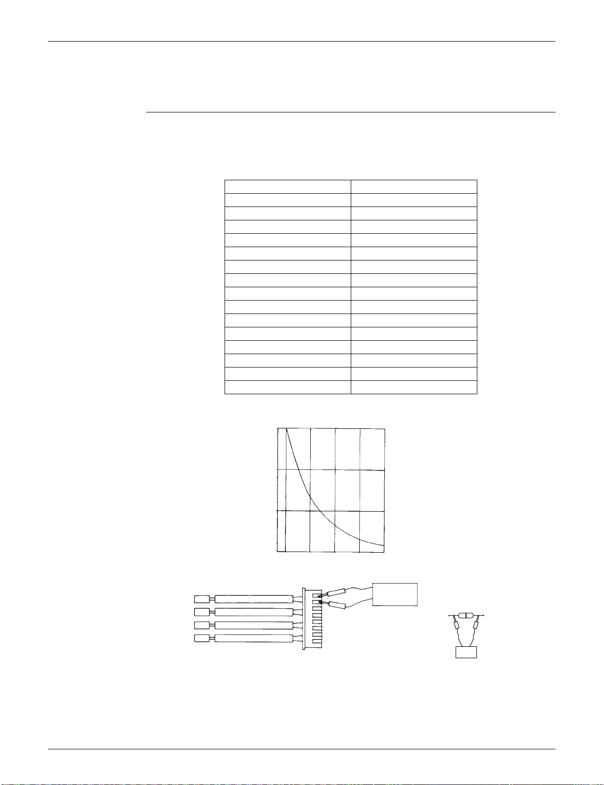
SiUS091133 Check
Service Diagnosis 142
5. Check
5.1 Thermistor Resistance Check
Check No.01 Disconnect the connectors of the thermistors from the PCB, and measure the resistance of each
thermistor using tester.
The relationship between normal temperature and resistance is shown in the table and the graph
below.
The data is for reference purpose only.
The room temperature thermistor is directly mounted on the display PCB. Remove the display
PCB from the control PCB to measure the resistance.
When the indoor heat exchanger thermistor is soldered on the PCB, remove the thermistor and
measure the resistance.
Temperature (°C / °F) Resistance (k)
–20 / –4 197.8
–15 / 5 148.2
–10 / 14 112.1
–5 / 23 85.60
0 / 32 65.93
5 / 41 51.14
10 / 50 39.99
15 / 59 31.52
20 / 68 25.02
25 / 77 20.00
30 / 86 16.10
35 / 95 13.04
40 / 104 10.62
45 / 113 8.707
50 / 122 7.176
(R25°C (77°F) = 20 k, B = 3950 K)
(kΩ)
150
100
50
–15 0 15 30 45
(R14467)
5 32 59 86 113
(˚C)
(˚F)
Tester
Resistance range
(R11906)
RTH1
Tester
(R3460)
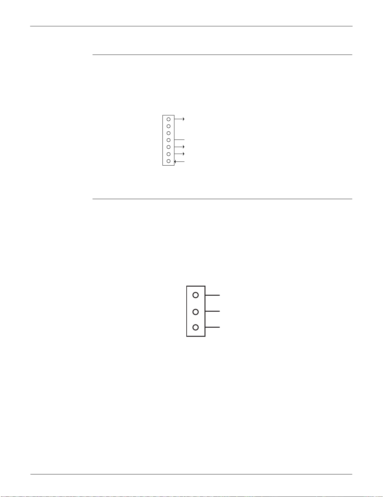
Check SiUS091133
143 Service Diagnosis
5.2 Fan Motor Connector Output Check
Check No.02 FTXS series
1. Check the connection of connector.
2. Check the motor power supply voltage output (pins 4 - 7).
3. Check the motor control voltage (pins 4 - 3).
4. Check the rotation command voltage (pins 4 - 2).
5. Check the rotation pulse (pins 4 - 1).
5.3 Hall IC Check
Check No.04 FDXS series
1. Check the connector connection.
2. With the power on, operation off, and the connector connected, check the following.
Output voltage of about 5 V between pins 1 and 3.
Generation of 3 pulses between pins 2 and 3 when the fan motor is operating.
If NG in step 1 Defective PCB Replace the PCB.
If NG in step 2 Defective Hall IC Replace the fan motor.
If OK in both steps 1 and 2 Replace the PCB.
7
6
5
4
3
2
1
S1
(R12404)
Motor power supply voltage (310 ~ 340 VDC)
Unused
Unused
GND
Motor control voltage (15 VDC)
Rotation command voltage (1~ 5 VDC)
Rotation pulse input
1
Gray (power supply)
Purple (signals)
Blue (grounding)
2
3
(R14211)
S7
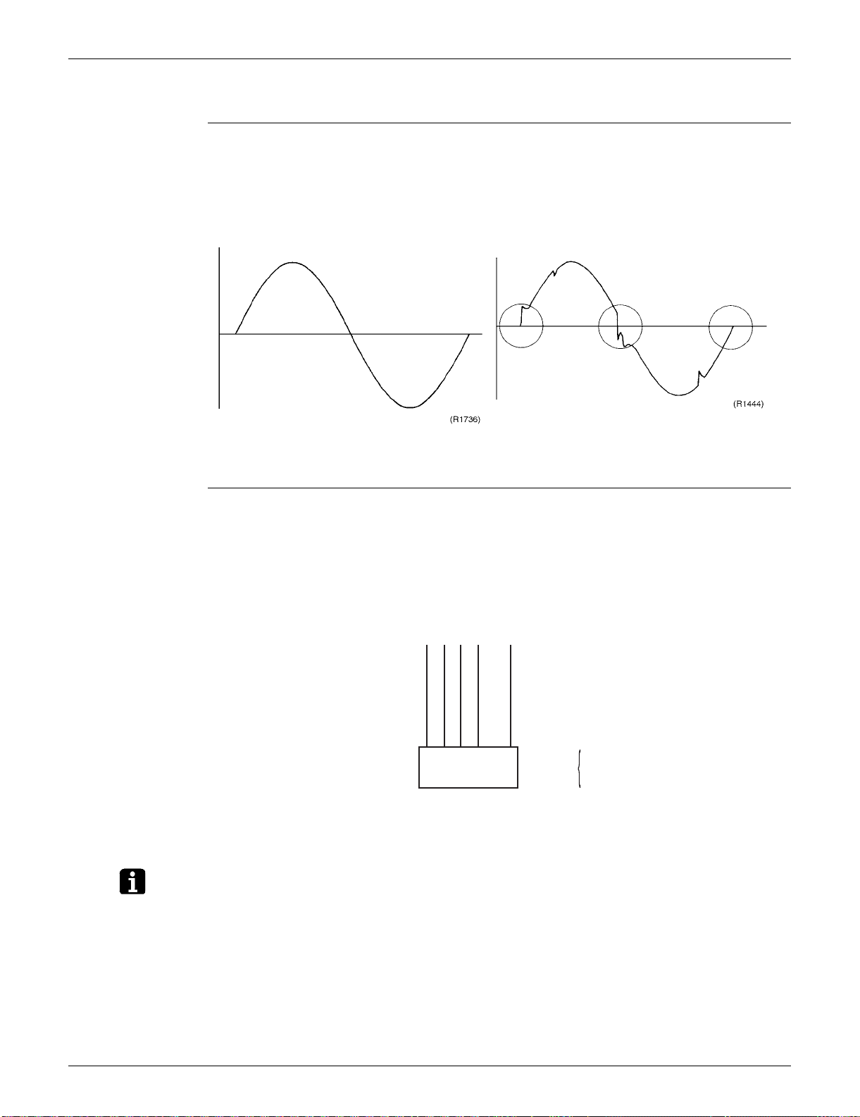
SiUS091133 Check
Service Diagnosis 144
5.4 Power Supply Waveforms Check
Check No.11 Measure the power supply waveform between No. 1 and No. 2 on the terminal board, and check
the waveform disturbance.
Check to see if the power supply waveform is a sine wave. (Fig.1)
Check to see if there is waveform disturbance near the zero cross. (sections circled in Fig.2)
5.5 Electronic Expansion Valve Check
Check No.12 Conduct the followings to check the electronic expansion valve (EV).
1. Check to see if the EV connector is correctly connected to the PCB.
2. Turn the power off and on again, and check to see if the EV generates a latching sound.
3. If the EV does not generate a latching sound in the above step 2, disconnect the connector and
check the continuity using a tester.
4. Check the continuity between the pins 1 - 6, 2 - 6, 3 - 6, and 4 - 6. If there is no continuity
between the pins, the EV coil is faulty.
5. If the continuity is confirmed in step 3, the outdoor unit PCB is faulty.
Note: Please note that the latching sound varies depending on the valve type.
Fig.1 Fig.2
Harness 5P
S20
6P Connector
(5)
Check
6-1
6-2
6-3
6-4
1 2 3 4 5 6
(R14212)
Check SiUS091133
145 Service Diagnosis
5.6 FourWay Valve Performance Check
Check No.13
5.7 Inverter Units Refrigerant System Check
Check No.14
(R15737)
NO
YES
YES
NO
Turn the power off and then on
again.
Disconnect the four-way valve coil
from the connector and check the
continuity.
Start heating operation.
* Four-way valve coil
Cooling / Dry : No continuity
Heating : Continuity
Replace the outdoor unit
PCB.
Replace the four-way valve
coil.
Replace the four-way valve.
Four-way valve
coil resistance at 1000 ~
2000 W?
S80 voltage at
220 - 240 VAC with
compressor on? (Fig.
1)
(R11904)
(Fig. 1)
Voltage at S80
220 - 240 VAC
Time
Compressor
ON
Refrigerant system check
Check for refrigerant leakage.
See the service diagnosis on
refrigerant shortage (U0).
(R15833)
YES
NO
Reconnect the thermistor.
Replace the refrigerant.
Is the
discharge pipe
thermistor disconnected
from the holder?
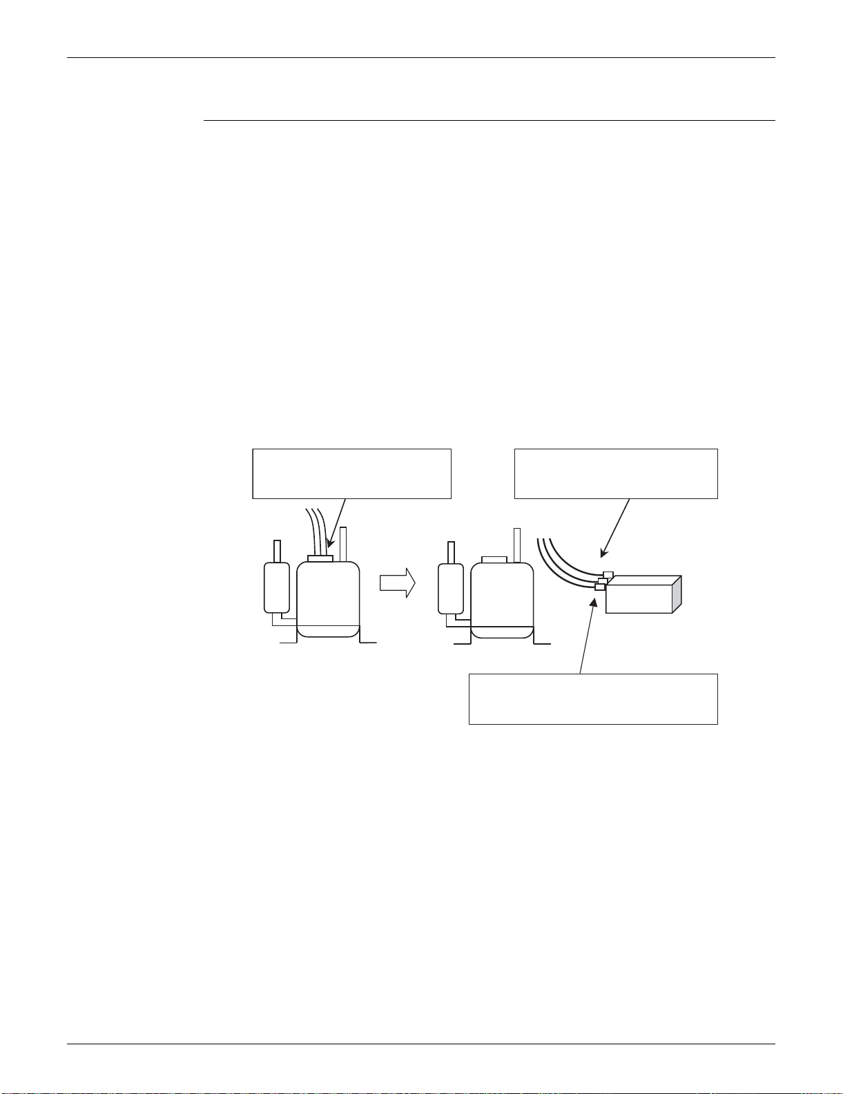
SiUS091133 Check
Service Diagnosis 146
5.8 “Inverter Checker” Check
Check No.15 Characteristics
If an abnormal stop occurs due to compressor startup failure or overcurrent output when using an
inverter unit, it is difficult to judge whether the stop is caused by the compressor failure or some
other failure (control PCB, power module, etc.). The inverter checker makes it possible to judge the
cause of trouble easily and securely. (Connect this checker as a quasi-compressor instead of
compressor and check the output of the inverter)
Operation Method
Step 1
Be sure to turn the power off.
Step 2
Install the inverter checker instead of a compressor.
Note:
Make sure the charged voltage of the built-in smoothing electrolytic capacitor drops to 10 VDC
or below before carrying out the service work.
Reference:
If the terminals of the compressor are not FASTON terminals (difficult to remove the wire on the
terminals), it is possible to connect wires available on site to the outdoor unit from output side of
PCB. (Do not connect them to the compressor at the same time, otherwise it may result in
incorrect detection.)
Step 3
Activate the power transistor test operation from the outdoor unit.
1) Press the forced cooling operation [ON/OFF] button for 5 seconds.
(Refer to page 384 for the position.)
Power transistor test operation starts.
(R14926)
(1) Remove the terminals from
the compressor.
(2) Connect the terminals to the
terminals of the inverter
checker.
Compressor
Inverter checker
Be careful not to let the terminals (U,V,W)
touch each other. Otherwise, high voltage
is applied.
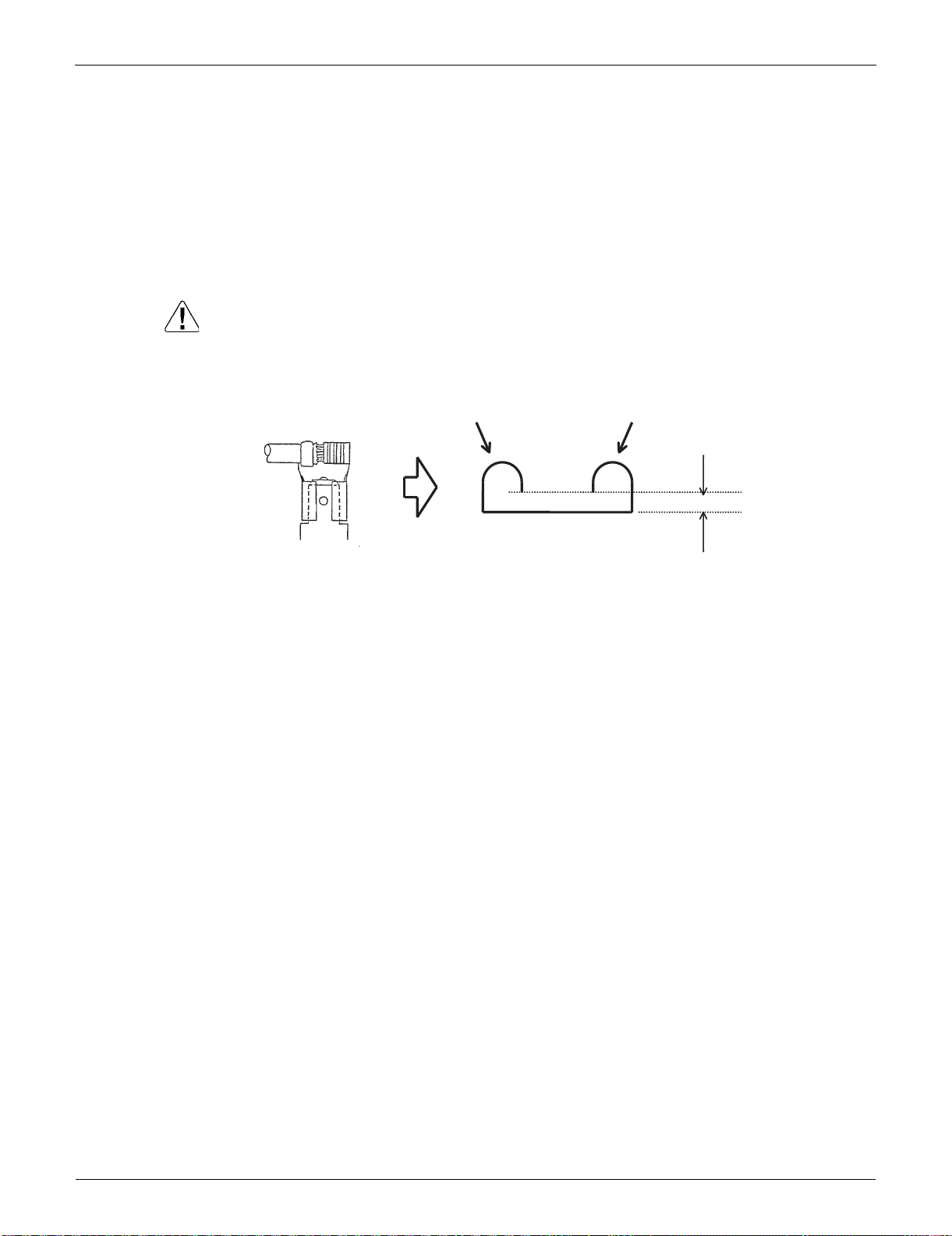
Check SiUS091133
147 Service Diagnosis
Diagnose method (Diagnose according to 6 LEDs lighting status.)
(1) If all the LEDs are lit uniformly, the compressor is defective.
Replace the compressor.
(2) If the LEDs are not lit uniformly, check the power module.
Refer to Check No.22.
(3) If NG in Check No.22, replace the power module.
(Replace the main PCB. The power module is united with the main PCB.)
If OK in Check No.22, check if there is any solder cracking on the PCB.
(4) If any solder cracking is found, replace the PCB or repair the soldered section.
If there is no solder cracking, replace the PCB.
Caution
(1) When the output frequency is low, the LEDs blink slowly. As the output frequency increases, the
LEDs blink quicker. (The LEDs look like they are lit.)
(2) On completion of the inverter checker diagnosis, be sure to re-crimp the FASTON terminals.
Otherwise, the terminals may be burned due to loosening.
(R15292)
Direction of crimp
FASTON terminal
This size is shortened
by the crimp.
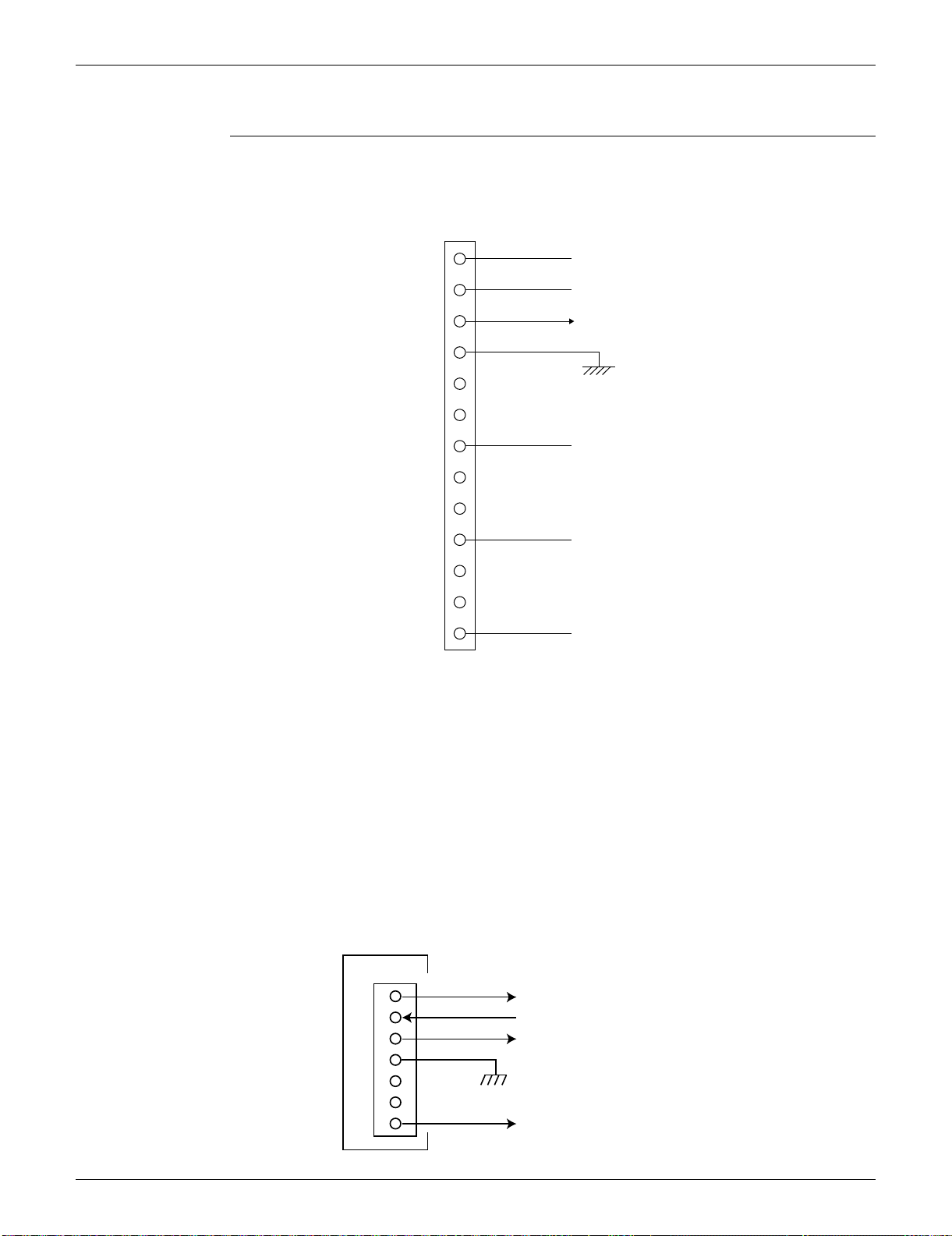
SiUS091133 Check
Service Diagnosis 148
5.9 Rotation Pulse Check on the Outdoor Unit PCB
Check No.16 09/12 class
1. Check that the voltage between the pins 10 - 11 is 15 VDC.
2. Check if the Hall IC generates the rotation pulse (0 ~ 15 VDC) 4 times between the pins 10 -12,
10 - 13, when the fan motor is manually rotated once.
15/18/24/30/36 class
Make sure that the voltage of 320 ± 30 V is applied.
1. Set operation off and power off. Disconnect the connector S70.
2. Check that the voltage between the pins 4 - 7 is 320 VDC.
3. Check that the control voltage between the pins 3 - 4 is 15 VDC.
4. Check that the rotation command voltage between the pins 2 - 4 is 0 ~ 15 VDC.
5. Keep operation off and power off. Connect the connector S70.
6. Check whether 2 pulses (0 ~ 15 VDC) are output at the pins 1 - 4 when the fan motor is rotated
1 turn by hand.
When the fuse is melted, check the outdoor fan motor for proper function.
If NG in step 2 Defective PCB Replace the outdoor unit PCB.
If NG in step 4 Defective Hall IC Replace the outdoor fan motor.
If OK in both steps 2 and 4 Replace the outdoor unit PCB.
13
12
11
10
9
8
7
6
5
4
3
2
1
S70
Phase U
15 VDC
Phase V
Phase W
HU (Hall IC)
HV (Hall IC)
Free pin
Free pin
Free pin
Free pin
Free pin
Free pin
(R11907)
1
2
3
4
5
6
7
320 VDC
(R10811)
S70
PCB
Actual rotation pulse output (0 ~ 15VDC)
Rotation command pulse input (0 ~ 15VDC)
15 VDC
Check SiUS091133
149 Service Diagnosis
5.10 Installation Condition Check
Check No.17
Installation condition check
OK
Check the allowable
dimensions of the air
suction and
discharge area.
Is the airflow blocked by
obstacles or winds
blowing in the opposite
direction?
(R17119)
NG
YES
YES
YES
Is the discharged air
short-circuited?
NO
NO
NO
Is the outdoor heat
exchanger very dirty?
Change the installation
location or direction.
Change the installation
location or direction.
Clean the outdoor heat
exchanger.
Change the installation
location or direction.
Check the outdoor temperature.
(The outdoor temperature
should be within operation
range.)
SiUS091133 Check
Service Diagnosis 150
5.11 Discharge Pressure Check
Check No.18
5.12 Outdoor Fan System Check
Check No.19 DC motor
(R15738)
Not dirty
YES
YES
Dirty
NO
NO
NO
YES
Is the air
filter or indoor / outdoor
heat exchanger
dirty?
Is the connection pipe
deformed?
Is the stop valve open?
High?
Replace the compressor.
Open the stop valve.
Replace the pipe installed at
the site.
Clean the dirty air filter or
indoor / outdoor heat
exchanger.
Replace the compressor.
Discharge pressure check
(R15001)
YES
YES
NO
NO
Outdoor fan system is functioning.
Check the outdoor fan system.
Go to Check No. 16.
Outdoor fan running?
Fan motor
lead wire connector
disconnected?
Reconnect the connector.
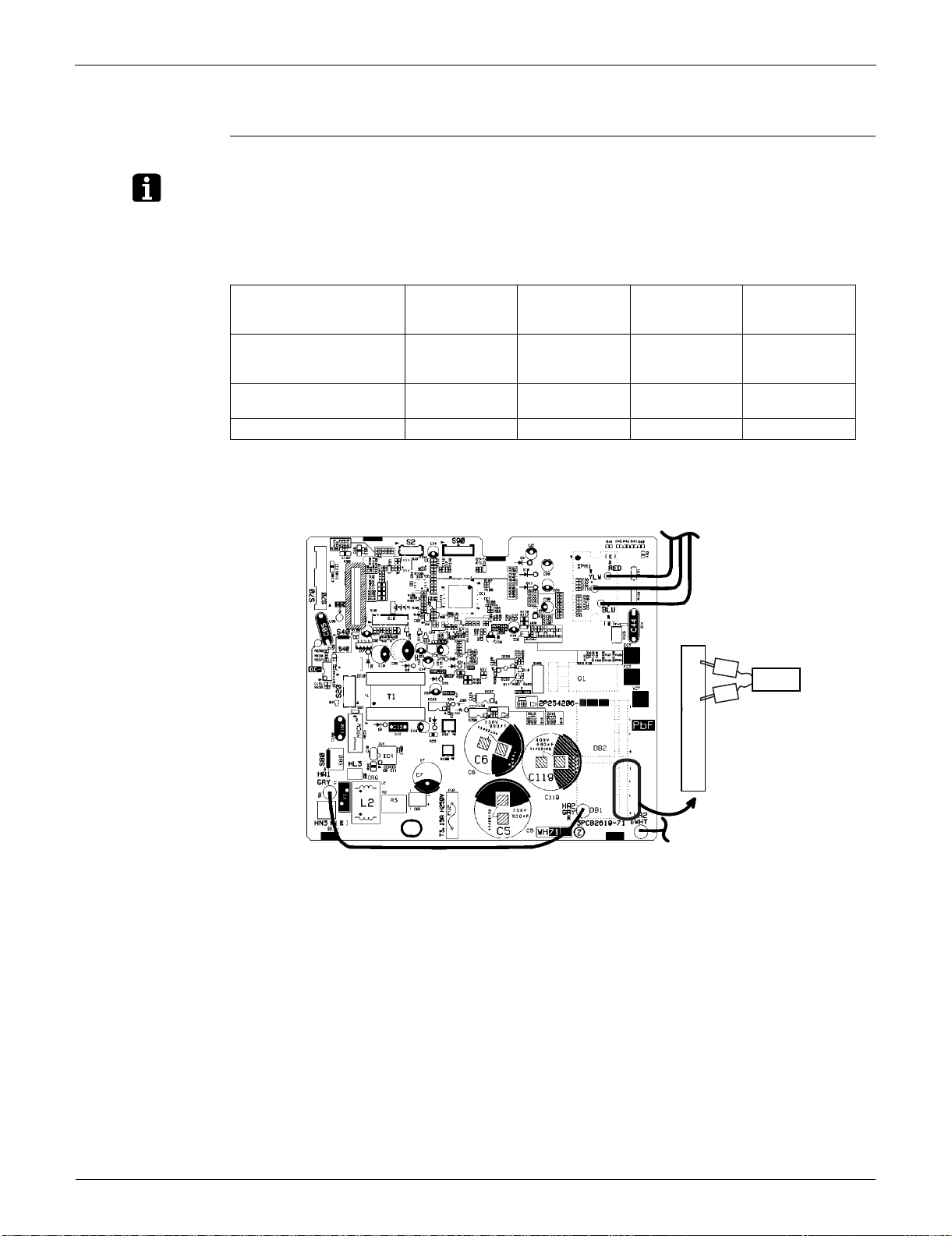
Check SiUS091133
151 Service Diagnosis
5.13 Main Circuit Short Check
Check No.20
Note: Check to make sure that the voltage between (+) and (–) of the diode bridge (DB1) is approx.
0 V before checking.
Measure the resistance between the pins of the DB1 referring to the table below.
If the resistance is or less than 1 k, short circuit occurs on the main circuit.
09/12 class
Negative (–) terminal of
tester (positive terminal
(+) for digital tester)
~ (2, 3) + (4) ~ (2, 3) – (1)
Positive (+) terminal of
tester (negative terminal
(–) for digital tester)
+ (4) ~ (2, 3) – (1) ~ (2, 3)
Resistance is OK. several k
~ several M
several k
~ several M
Resistance is NG. 0 or 000 or
(R12035)
Tester
–~~+
1
2
3
4
–
+
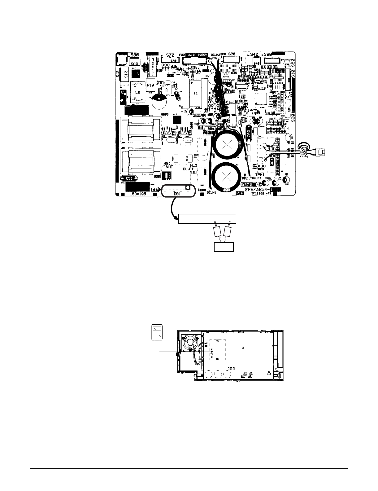
SiUS091133 Check
Service Diagnosis 152
15/18 class
5.14 Capacitor Voltage Check
Check No.21 Before this check, be sure to check the main circuit for short circuit.
With the circuit breaker still on, measure the voltage according to the drawing of the model in
question. Be careful never to touch any live parts.
Tester
–~~+
1234
–
+
(R14700)
Multimeter
(DC voltage range)
(R13538)
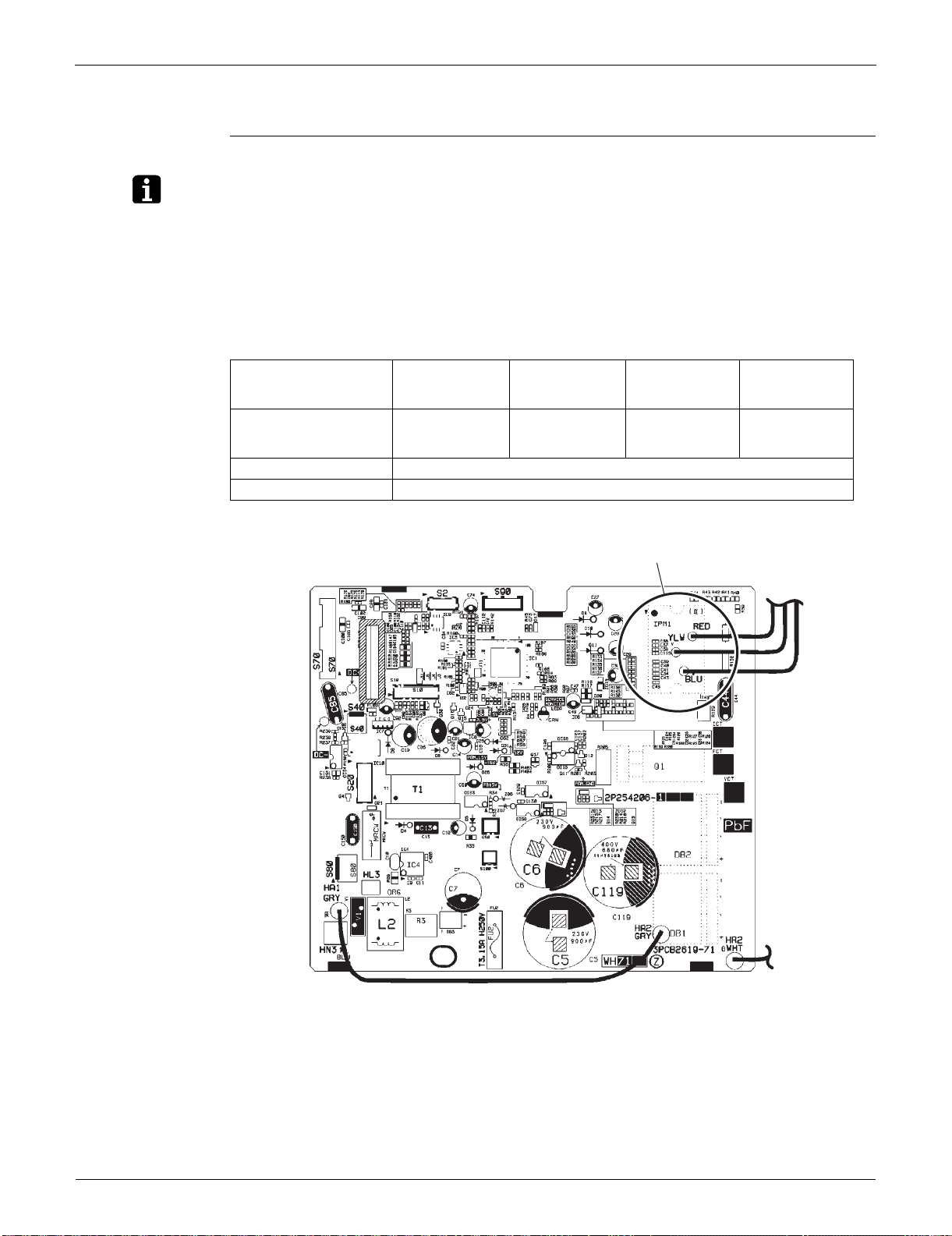
Check SiUS091133
153 Service Diagnosis
5.15 Power Module Check
Check No.22
Note: Check to make sure that the voltage between (+) and (–) of the power module is approx. 0 V before
checking.
Disconnect the compressor harness connector from the outdoor unit PCB. To disengage the
connector, press the protrusion on the connector.
Follow the procedure below to measure resistance between the terminals of the power module
and the terminals of the compressor with a multi-tester. Evaluate the measurement results
referring to the following table.
09/12 class
Negative (–) terminal of
tester (positive terminal
(+) for digital tester)
Power module
(+)
UVW Power module
(–)
UVW
Positive (+) terminal of
tester (negative terminal
(–) for digital tester)
UVW Power module
(+)
UVW Power module
(–)
Resistance is OK. several k ~ several M
Resistance is NG. 0 or
(R16069)
Power module
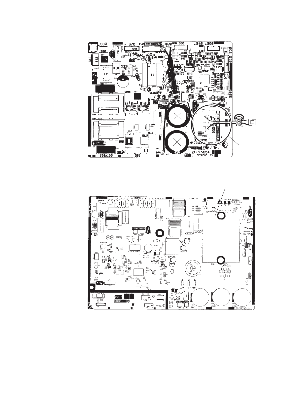
SiUS091133 Check
Service Diagnosis 154
15/18 class
24/30/36 class
Power module
(R16697)
(R16073)
Power module

SiUS091133
155 Removal Procedure
Part 7
Removal Procedure
1. Indoor Unit: FTXS09/12LVJU..................................................................157
1.1 Removal of Air Filters...............................................................................157
1.2 Removal of Front Panel............................................................................159
1.3 Removal of Front Grille ............................................................................160
1.4 Removal of Horizontal Blades / Vertical Blades.......................................162
1.5 Removal of Electrical Box ........................................................................166
1.6 Removal of PCBs.....................................................................................170
1.7 Removal of Swing Motors ........................................................................ 176
1.8 Removal of Indoor Heat Exchanger.........................................................180
1.9 Removal of Fan Motor..............................................................................183
2. Indoor Unit: FTXS15/18/24LVJU.............................................................186
2.1 Removal of Air Filters / Front Panel .........................................................186
2.2 Removal of Front Grille ............................................................................189
2.3 Removal of Electrical Box ........................................................................192
2.4 Removal of PCBs.....................................................................................196
2.5 Removal of Horizontal Blades / Swing Motors.........................................205
2.6 Removal of Indoor Heat Exchanger.........................................................213
2.7 Removal of Fan Motor / Fan Rotor...........................................................217
2.8 Removal of Vertical Blade ASSYs............................................................220
3. Indoor Unit: FTXS30/36LVJU..................................................................221
3.1 Removal of Air Filters / Front Panel .........................................................221
3.2 Removal of Front Grille ............................................................................224
3.3 Removal of Electrical Box ........................................................................228
3.4 Removal of PCBs.....................................................................................232
3.5 Removal of Horizontal Blades / Swing Motors.........................................241
3.6 Removal of Fan Motor..............................................................................250
3.7 Removal of Indoor Heat Exchanger.........................................................254
3.8 Removal of Fan Rotor..............................................................................258
3.9 Removal of Vertical Blade ASSYs............................................................260
4. Outdoor Unit: RXS09/12LVJU.................................................................261
4.1 Removal of Outer Panels / Fan Motor......................................................261
4.2 Removal of Electrical Box ........................................................................270
4.3 Removal of PCBs.....................................................................................273
4.4 Removal of Reactor / Partition Plate........................................................281
4.5 Removal of Sound Blankets.....................................................................283
4.6 Removal of FourWay Valve......................................................................285
4.7 Removal of Compressor...........................................................................288
5. Outdoor Unit: RXS15/18LVJU.................................................................290
5.1 Removal of Outer Panels.........................................................................290
5.2 Removal of Outdoor Fan / Fan Motor.......................................................293
5.3 Removal of Electrical Box ........................................................................297

SiUS091133
Removal Procedure 156
5.4 Removal of PCBs.....................................................................................308
5.5 Removal of Sound Blankets / Thermistors...............................................316
5.6 Removal of FourWay Valve......................................................................320
5.7 Removal of Electronic Expansion Valve...................................................321
5.8 Removal of Compressor...........................................................................323
6. Outdoor Unit: RXS24LVJU......................................................................326
6.1 Removal of Outer Panels.........................................................................326
6.2 Removal of Electrical Box ........................................................................340
6.3 Removal of PCBs.....................................................................................344
6.4 Removal of Fan Motor..............................................................................347
6.5 Removal of Coils / Thermistors................................................................ 348
6.6 Removal of Sound Blankets.....................................................................351
6.7 Removal of Compressor...........................................................................354
7. Outdoor Unit: RKS30/36LVJU, RXS30/36LVJU .....................................356
7.1 Removal of Outer Panels.........................................................................356
7.2 Removal of Electrical Box ........................................................................367
7.3 Removal of PCBs.....................................................................................371
7.4 Removal of Fan Motor..............................................................................374
7.5 Removal of Coils / Thermistors................................................................ 375
7.6 Removal of Sound Blankets.....................................................................378
7.7 Removal of Compressor...........................................................................380
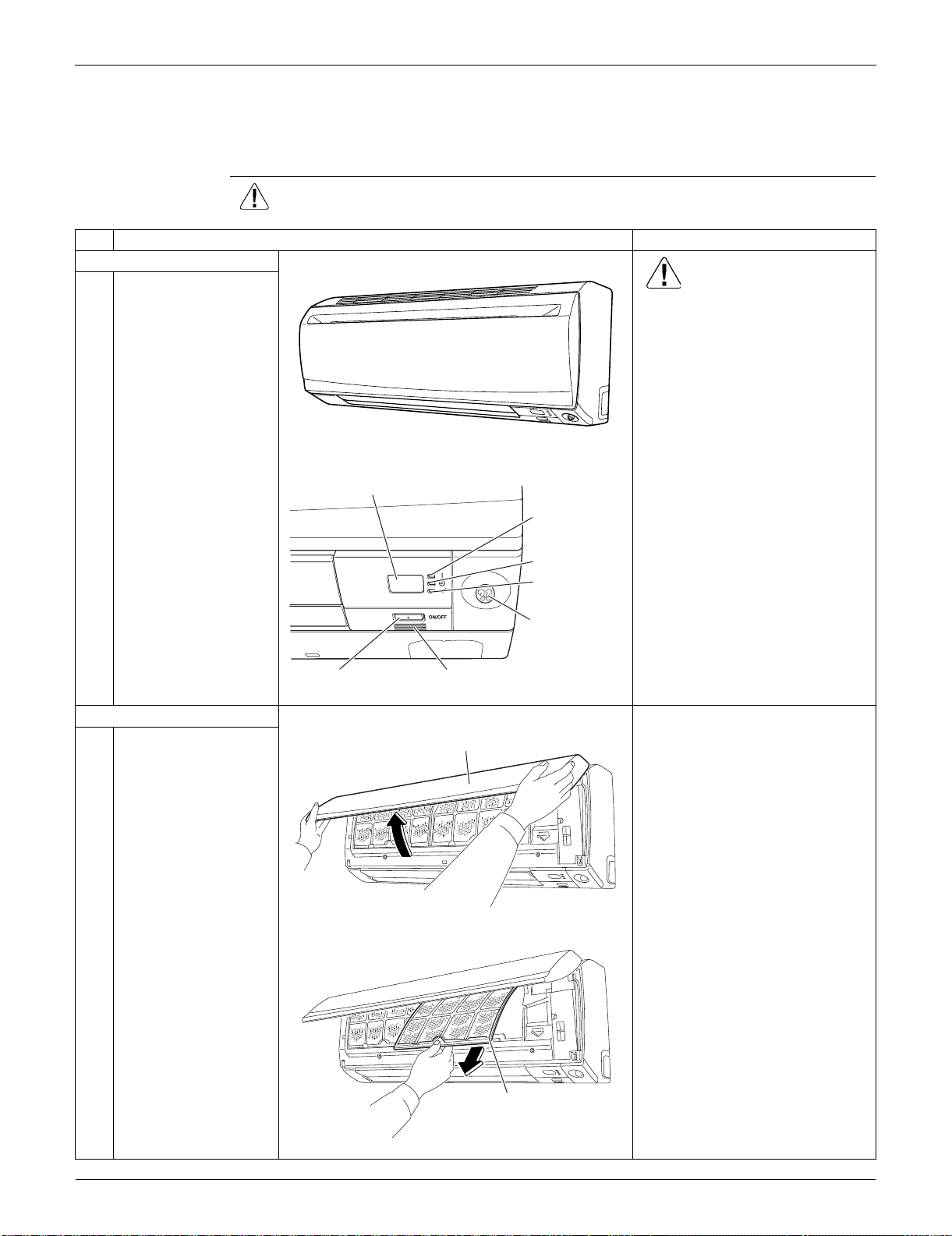
Indoor Unit: FTXS09/12LVJU SiUS091133
157 Removal Procedure
1. Indoor Unit: FTXS09/12LVJU
1.1 Removal of Air Filters
Procedure Warning Be sure to wait for 10 minutes or more after turning off all power supplies
before disassembling work.
Step
Procedure Points
1. Appearance features
Warning
Dangerous: High voltage
A high voltage is applied to all
the electric circuits of this
product including thermistors.
When the signal receiver
catches a signal from the
remote controller, the receiving
tone sounds and the operation
lamp blinks immediately to
confirm the signal reception.
When the [ON/OFF] button is
kept pressed for 5 seconds, the
forced cooling operation is
performed for about 15 minutes.
2. Remove the air filters.
1
Open the front panel to
the position where it
stops.
2
Slightly push up the
center knob of the air
filter and release the
hooks.
The air filter is not marked for
difference between the right and
left sides.
The air filter can be set easily by
inserting it along the guides.
Insert the air filter with the
"FRONT" mark faced up.
Be sure to insert the hooks (at 2
lower positions) when
reassembling the air filter.
3
Pull out the air filter
downward and remove
it.
(R7900)
(R7901)
Signal receiver
Operation lamp
TIMER lamp
[ON/OFF] button Room temperature thermistor
INTELLIGENT
EYE sensor
INTELLIGENT
EYE lamp
(R7902)
Front panel
(R7903)
Air filter
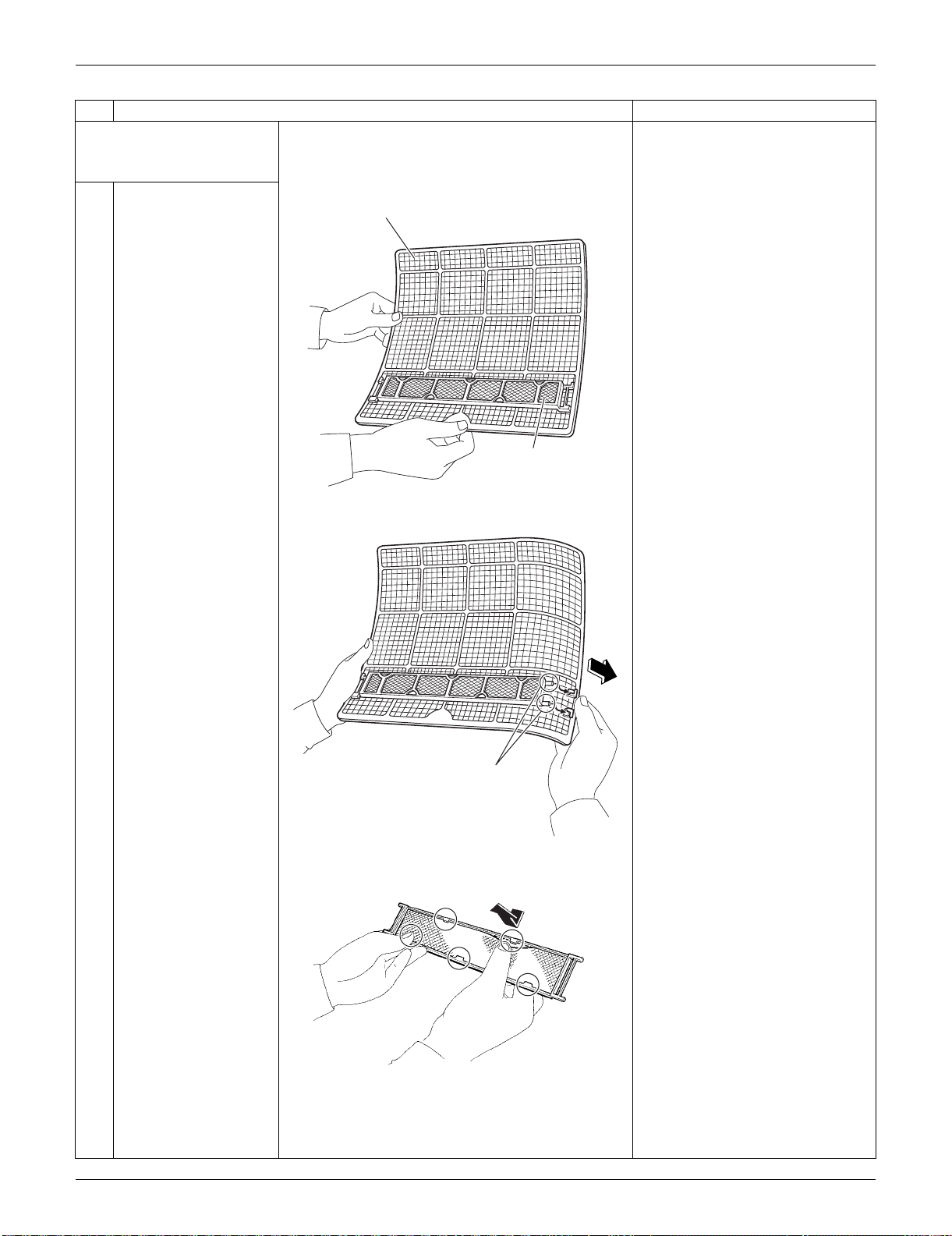
SiUS091133 Indoor Unit: FTXS09/12LVJU
Removal Procedure 158
3. Remove the Titanium
apatite photocatalytic air-
purifying filters.
1
The Titanium apatite
photocatalytic air-
purifying filter ASSY is
attached to the back of
the air filter.
The right and left filters are
interchangeable.
2
Remove the Titanium
apatite photocatalytic
air-purifying filter ASSY
by unfastening the
projections from the
back of the air filter
frame.
3
Unfasten the 5 hooks
and remove the
Titanium apatite
photocatalytic air-
purifying filter from its
frame.
Step
Procedure Points
(R7904)
Air filter
Titanium apatite
photocatalytic
air-purifying filter ASSY
(R13487)
Projection
(R13174)
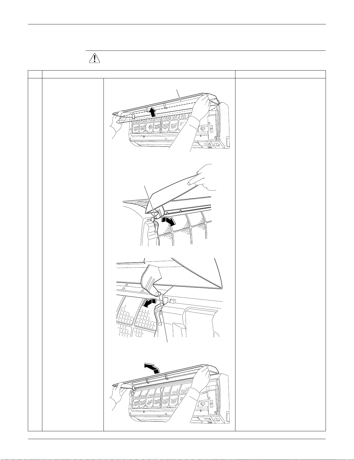
Indoor Unit: FTXS09/12LVJU SiUS091133
159 Removal Procedure
1.2 Removal of Front Panel
Procedure Warning Be sure to wait for 10 minutes or more after turning off all power supplies
before disassembling work.
Step
Procedure Points
1
Open the front panel
over the position where
it stops.
2
Slide the left rotary
shaft to the right and
release it.
When reassembling the front
panel, fit the right and left rotary
shafts one by one into the
grooves and fully push them into
position.
3
Slide the right rotary
shaft to the left and
release it.
4
Remove the front
panel.
(R7906)
Front panel
(R7907)
Rotary shaft
(R7909)
Rotary shaft
(R7910)
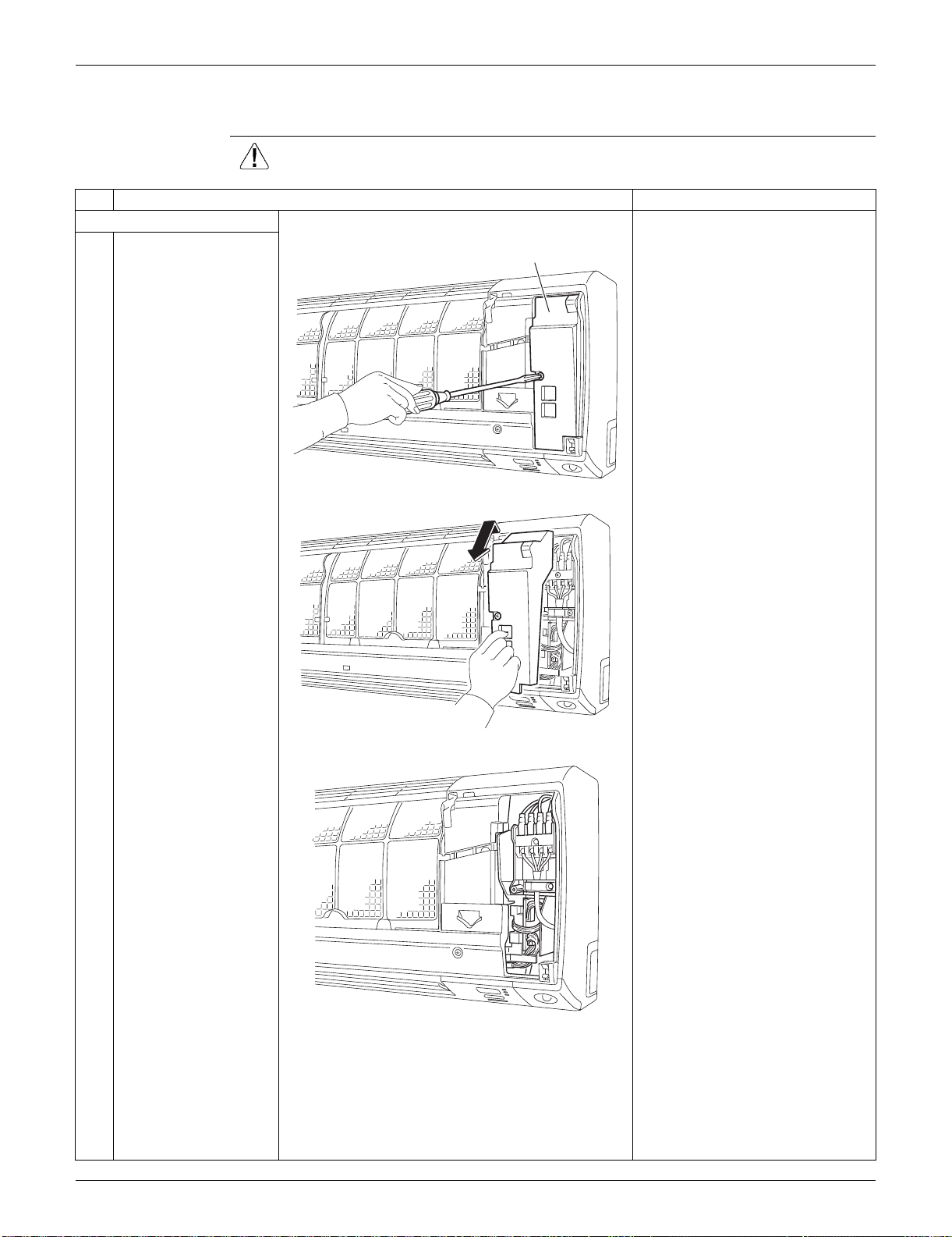
SiUS091133 Indoor Unit: FTXS09/12LVJU
Removal Procedure 160
1.3 Removal of Front Grille
Procedure Warning Be sure to wait for 10 minutes or more after turning off all power supplies
before disassembling work.
Step
Procedure Points
1. Remove the service cover.
1
Remove the screw of
the service cover.
Preparation
Remove the front panel
according to the “Removal of
Front Panel”.
2
Pull out the service
cover diagonally down
in the direction of the
arrow.
3
The figure shows the
inside.
(R7911)
Service cover
(R13488)
(R13489)
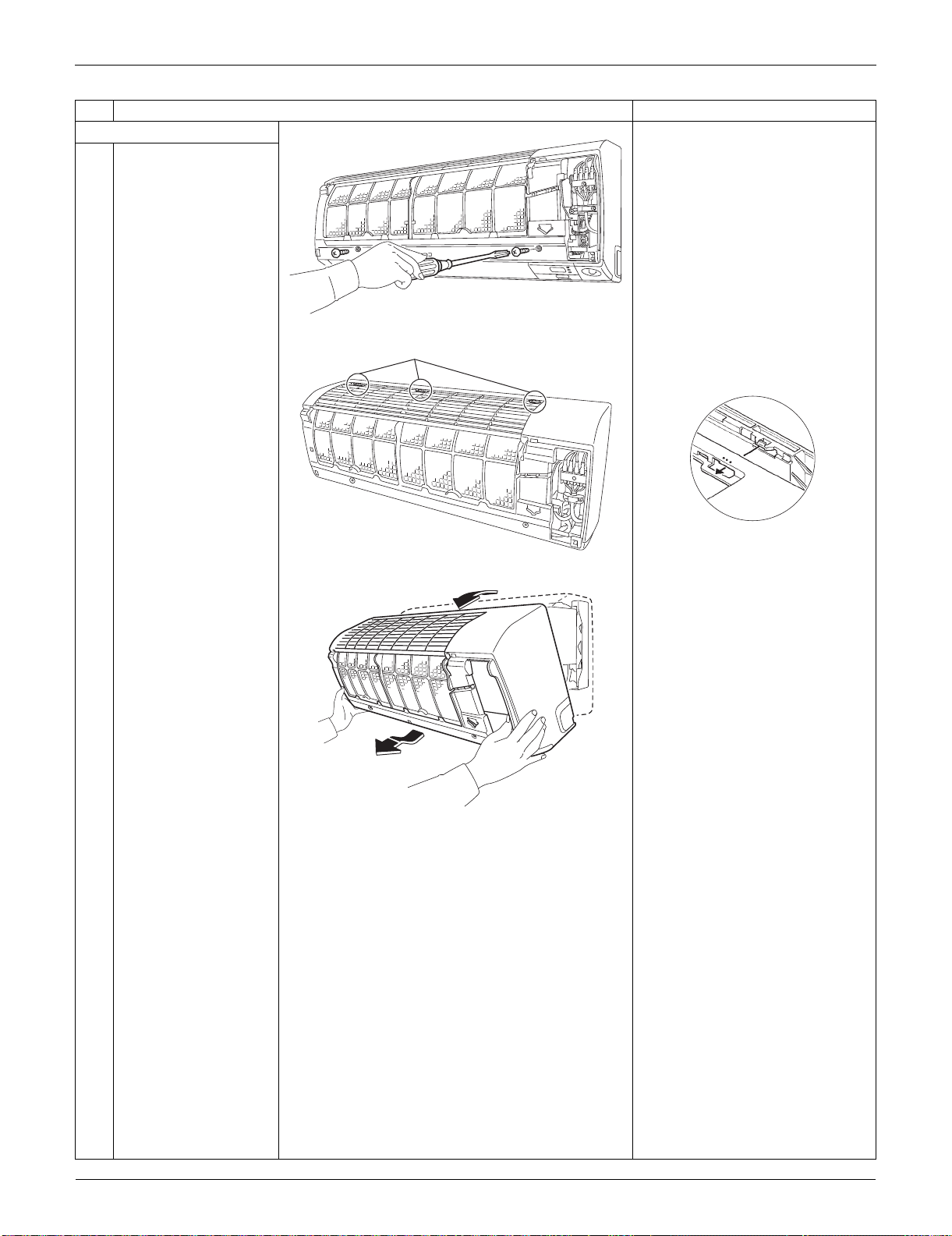
Indoor Unit: FTXS09/12LVJU SiUS091133
161 Removal Procedure
2. Remove the front grille.
1
Remove the 2 screws.
2
Unfasten the 3 hooks at
the top.
The convex marks (...) on the
front panel indicate the position
of the hooks.
3
Pull the upper part of
the front grille out and
lift the lower part up,
and then remove the
front grille.
When reassembling, make sure
that all the 3 hooks are fastened
as they were.
Step
Procedure Points
(R13490)
(R13491)
Hook
(R12715)
(R12268)
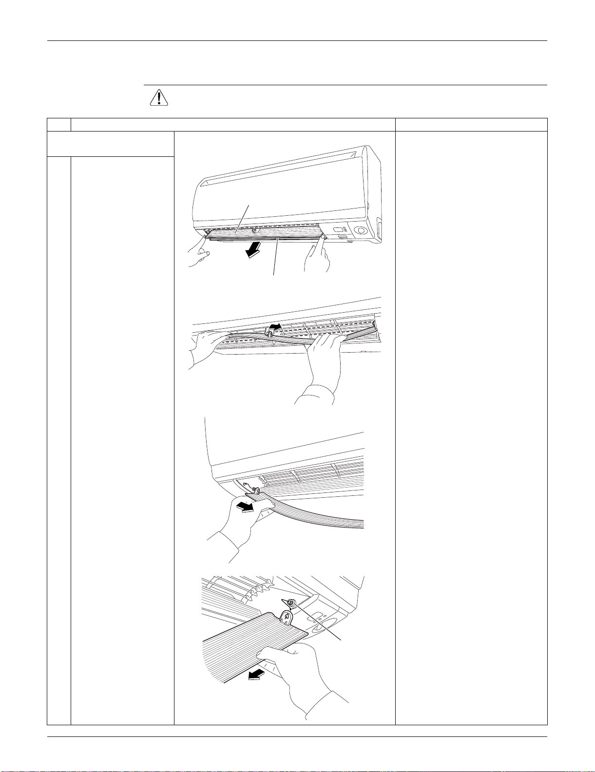
SiUS091133 Indoor Unit: FTXS09/12LVJU
Removal Procedure 162
1.4 Removal of Horizontal Blades / Vertical Blades
Procedure Warning Be sure to wait for 10 minutes or more after turning off all power supplies
before disassembling work.
Step
Procedure Points
1. Remove the horizontal
blade (large).
1
Open the horizontal
blade (large).
When reassembling, mount the
large horizontal blade to the
upper position and the small
horizontal blade to the lower
position.
Do not put them in the wrong
place.
2
Unfasten the center
shaft while bending the
horizontal blade (large)
slightly.
3
Unfasten the left shaft.
4
Unfasten the right shaft. There is a key alignment at the
right shaft. When reassembling,
insert the right shaft first while
turning.
After inserting the right shaft,
first mount the horizontal blade
to the center shaft and then to
the left shaft.
(R7921)
Horizontal blade (large)
Horizontal blade (small)
(R7922)
(R7923)
(R13738)
Key alignment
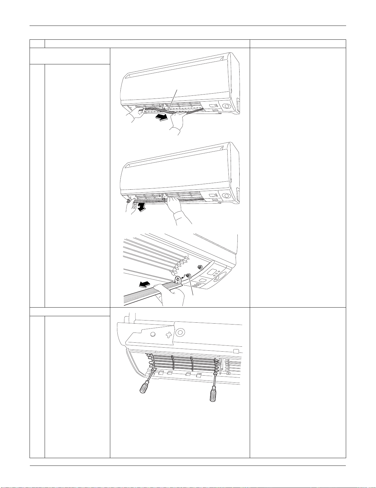
Indoor Unit: FTXS09/12LVJU SiUS091133
163 Removal Procedure
2. Remove the horizontal
blade (small).
1
Unfasten the center
shaft while bending the
horizontal blade (small)
slightly.
2
Unfasten the left shaft.
3
Unfasten the right shaft. There is a key alignment at the
right shaft. When reassembling,
insert the right shaft first while
turning.
After inserting the right shaft,
first mount the horizontal blade
to the center shaft, and then to
the left shaft.
3. Remove the fan guard.
1
Unfasten the hooks at
the lower part of the fan
guard with a flat
screwdriver.
Step
Procedure Points
(R7925)
Horizontal blade (small)
(R7926)
(R13737)
Key alignment
(R13751)
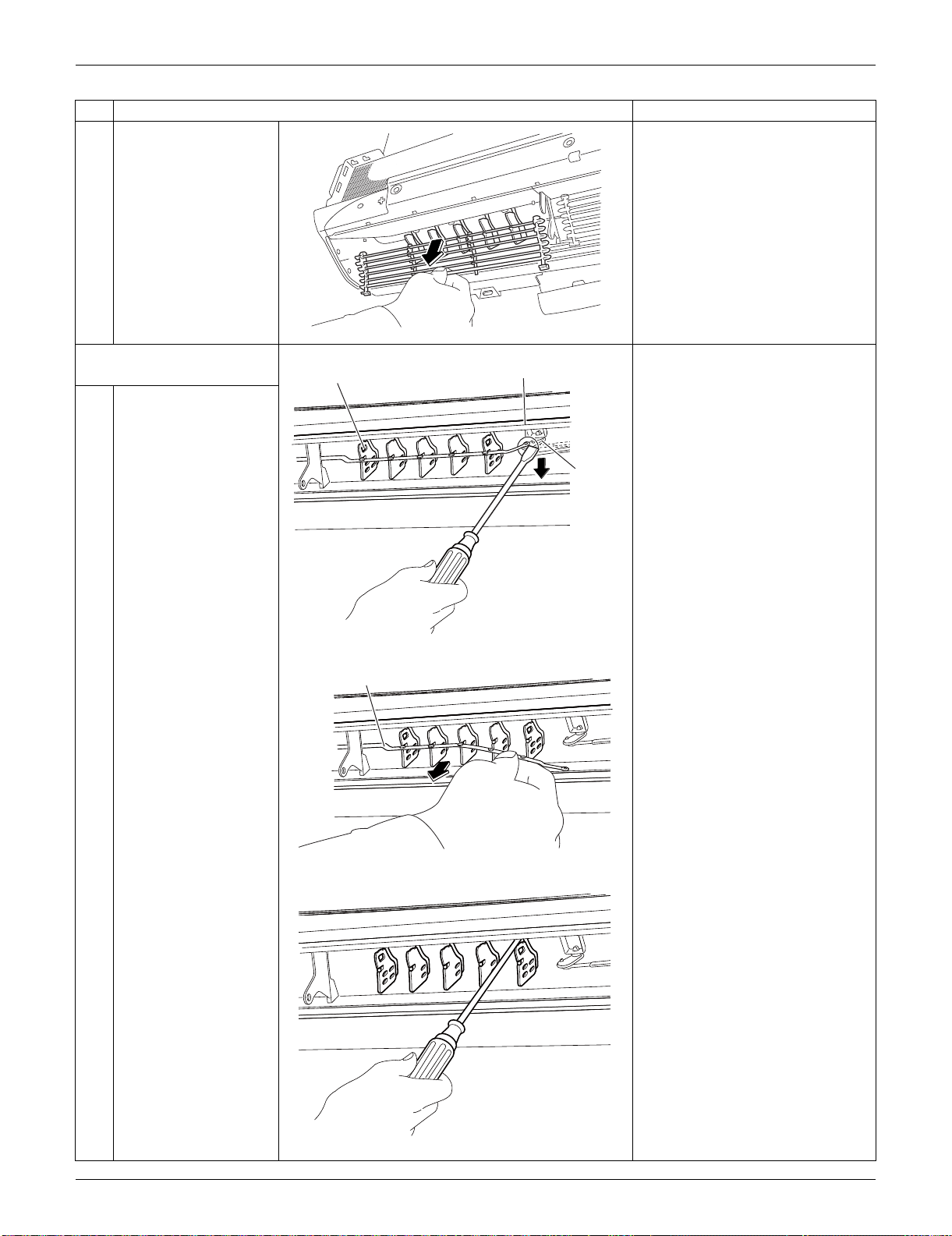
SiUS091133 Indoor Unit: FTXS09/12LVJU
Removal Procedure 164
2
Remove the fan guard.
4. Remove the vertical blade
ASSYs.
1
Detach the pivot from
the interlock shaft for
vertical blades with a
flat screwdriver.
2
Remove the interlock
rod.
3
Unfasten the hooks at
the upper 3 positions by
pressing them with a
flat screwdriver.
Step
Procedure Points
(R8079)
(R13092)
Vertical blade ASSY
Pivot
Interlock
shaft
(R13093)
Interlock rod
(R13094)
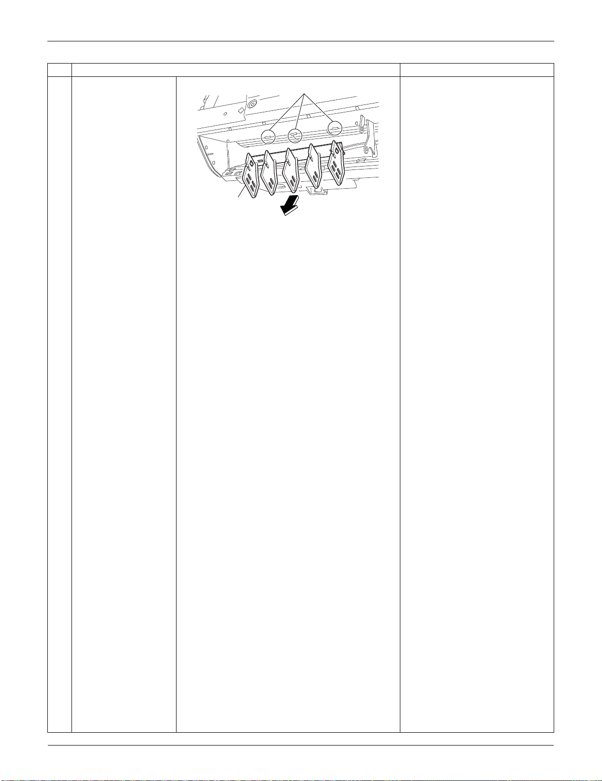
Indoor Unit: FTXS09/12LVJU SiUS091133
165 Removal Procedure
4
Remove the vertical
blade ASSY.
A vertical blade ASSY has 5
fins.
It is impossible to replace only
one fin.
The vertical blade ASSY is not
marked for difference between
right and left.
Step
Procedure Points
(R13095)
Hook
Vertical blade
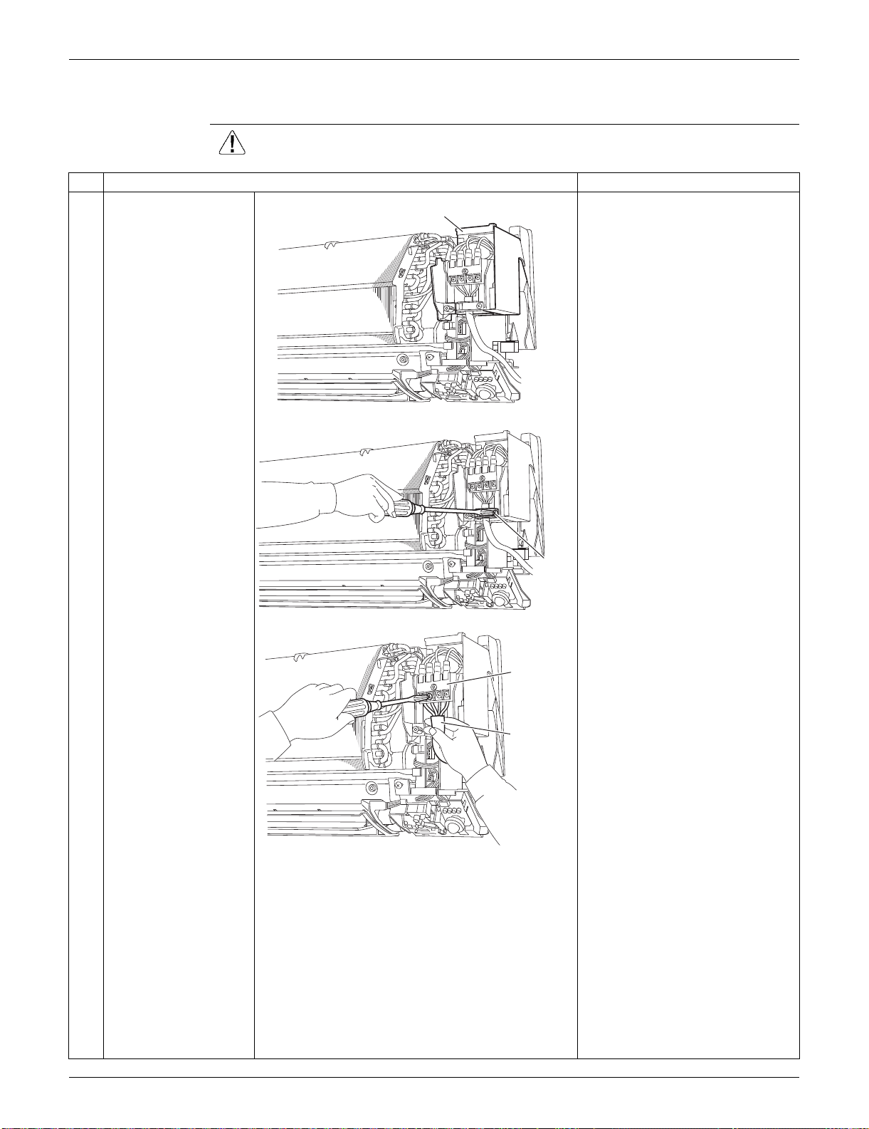
SiUS091133 Indoor Unit: FTXS09/12LVJU
Removal Procedure 166
1.5 Removal of Electrical Box
Procedure Warning Be sure to wait for 10 minutes or more after turning off all power supplies
before disassembling work.
Step
Procedure Points
1
The figure shows the
connections of the wire
harnesses.
Preparation
Remove the front grille
according to the “Removal of
Front Grille”.
2
Remove the screw of
the wire retainer.
3
Remove the 4 screws
of the terminal board
and disconnect the
connection wires.
(R13496)
Electrical box
(R13497)
Wire
retainer
(R16968)
Terminal
board
Connection
wire
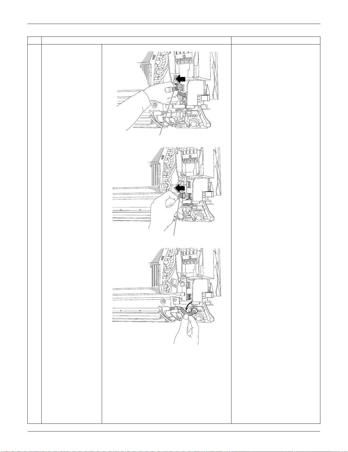
Indoor Unit: FTXS09/12LVJU SiUS091133
167 Removal Procedure
4
Disconnect the
connector for the fan
motor [S1].
5
Disconnect the
connector for the swing
motors [S41].
6
Release the harness for
the swing motors from
the hook.
Step
Procedure Points
(R13499)
[S1]
(R7935)
[S41]
(R7936)
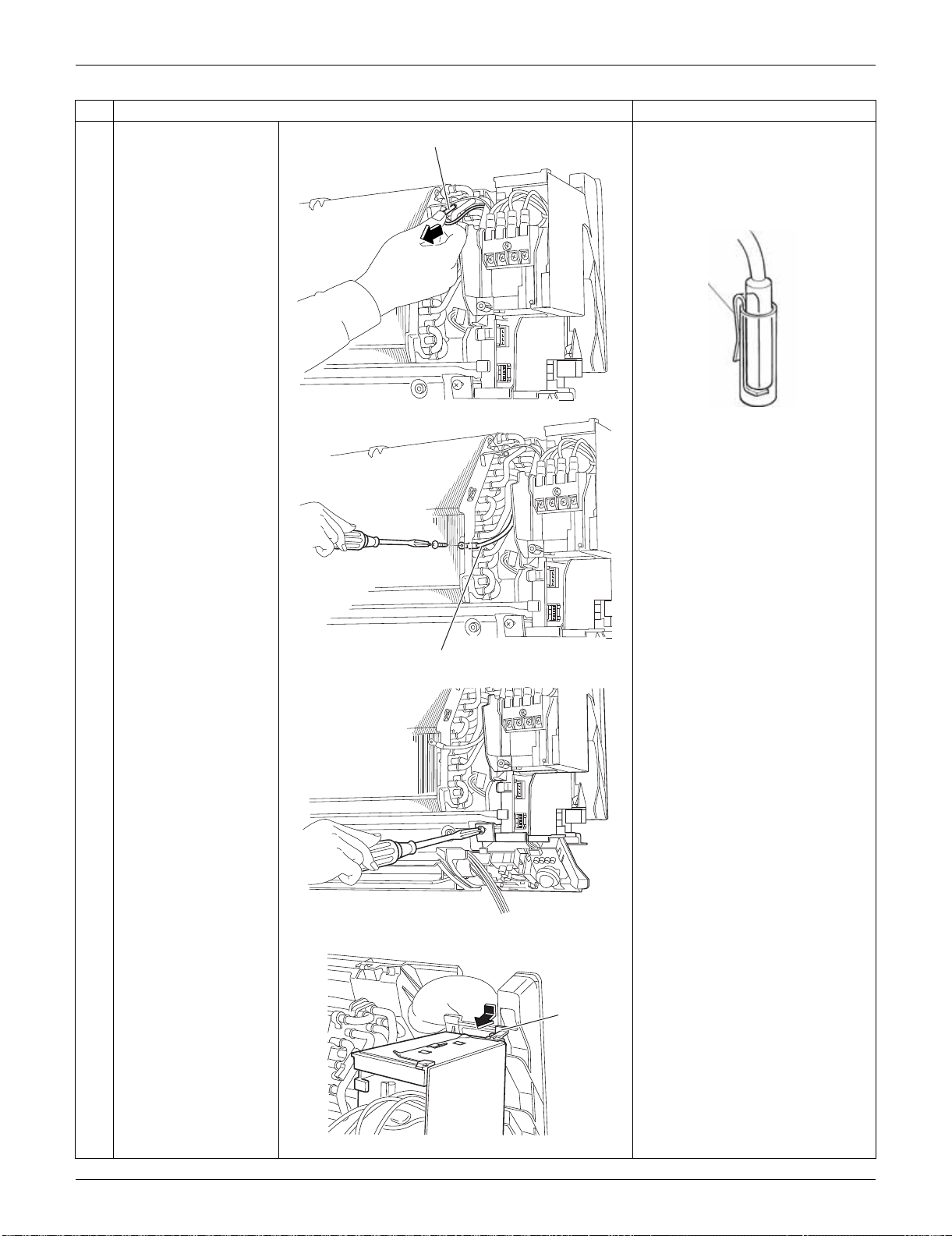
SiUS091133 Indoor Unit: FTXS09/12LVJU
Removal Procedure 168
7
Pull out the indoor heat
exchanger thermistor.
The position of the indoor heat
exchanger thermistor varies by
model.
Be careful not to lose the clip of
the thermistor.
8
Remove the screw and
detach the ground wire.
9
Remove the screw of
the electrical box.
10
Unfasten the hook at
the upper far side by
pressing it from above
and pulling the
electrical box.
Step
Procedure Points
(R7937)
Indoor heat exchanger thermistor
Clip
(R11268)
(R16969)
Ground wire
(R3939)
(R8081)
Hook
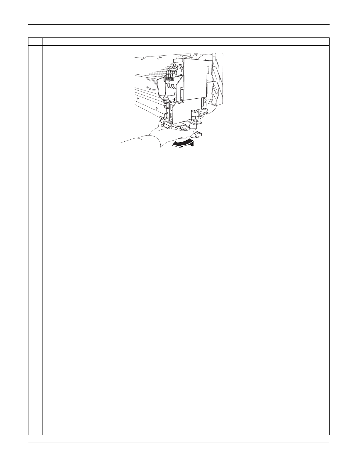
Indoor Unit: FTXS09/12LVJU SiUS091133
169 Removal Procedure
11
Lift up the electrical box
and pull it out.
There is a hook also at the lower
part of the back. When
reassembling the electrical box,
make sure that it is securely
fastened.
Step
Procedure Points
(R8082)
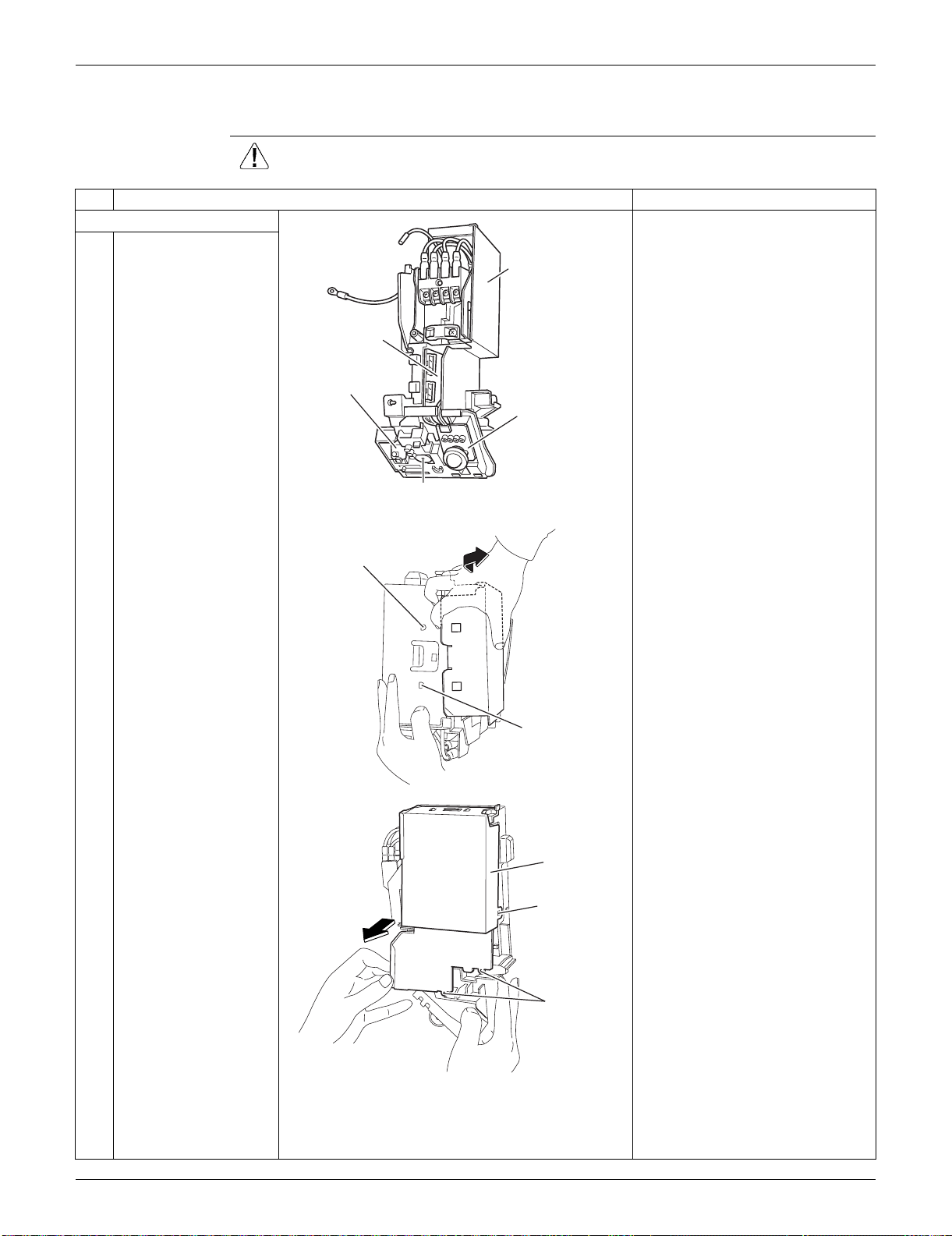
SiUS091133 Indoor Unit: FTXS09/12LVJU
Removal Procedure 170
1.6 Removal of PCBs
Procedure Warning Be sure to wait for 10 minutes or more after turning off all power supplies
before disassembling work.
Step
Procedure Points
1. Remove the shield plate.
1
The figure shows the
appearance of the
electrical box.
Preparation
Remove the electrical box
according to the “Removal of
Electrical Box”.
2
Unfasten the hooks at
the upper 2 positions of
the shield plate.
3
Unfasten the hook at
the side of the shield
plate.
4
Lift up the shield plate
to unfasten the lower
hooks and remove it.
(R13747)
Signal receiver PCB
Control PCB
Display PCB
(inside)
Shield plate
INTELLIGENT EYE
sensor PCB
(R8085)
Hook
Hook
(R10619)
Shield plate
Hook (side)
Hook (lower)
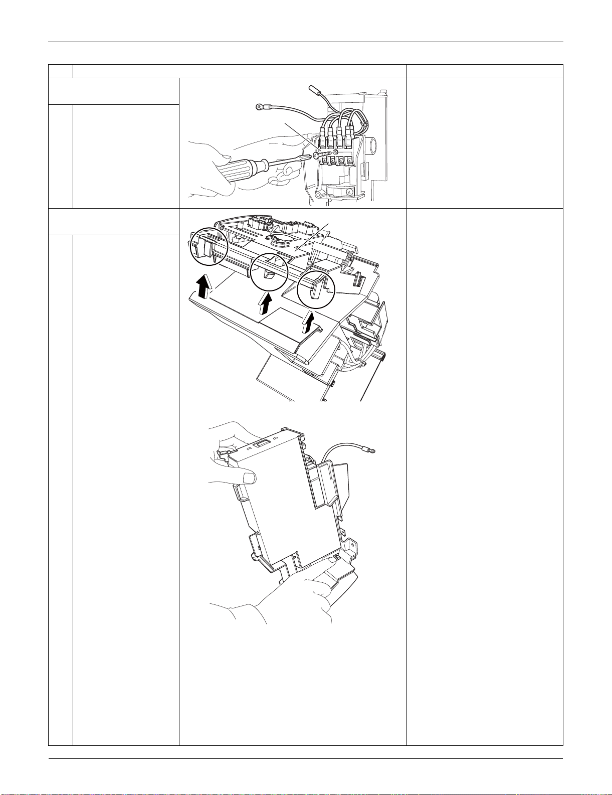
Indoor Unit: FTXS09/12LVJU SiUS091133
171 Removal Procedure
2. Remove the terminal
board.
1
Remove the screw and
remove the terminal
board.
3. Remove the signal
receiver unit.
1
Unfasten the 3 hooks.
2
Unfasten the hook on
the opposite side, and
lift up the signal
receiver unit.
Step
Procedure Points
(R10315)
Terminal board
(R12277)
Signal receiver unit
(R8262)
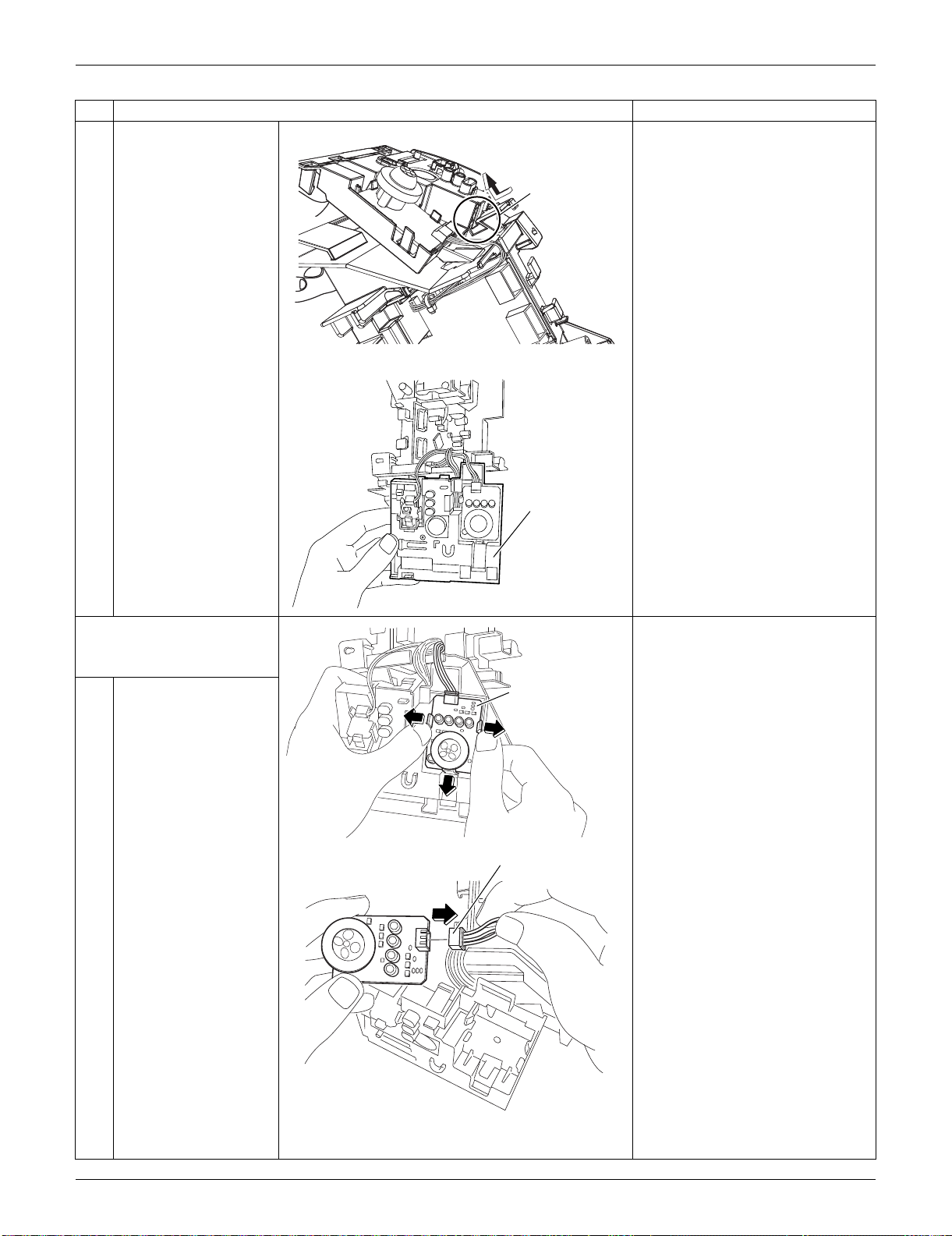
SiUS091133 Indoor Unit: FTXS09/12LVJU
Removal Procedure 172
3
Remove the signal
receiver unit.
4. Remove the
INTELLIGENT EYE
sensor PCB.
1
Unfasten the 3 hooks
and remove the
INTELLIGENT EYE
sensor PCB.
2
Disconnect the
connector [S26] from
the INTELLIGENT EYE
sensor PCB.
Step
Procedure Points
(R12278)
Hook
(R8088)
Signal receiver unit
(R8092)
INTELLIGENT EYE
sensor PCB
(R8093)
[S26]
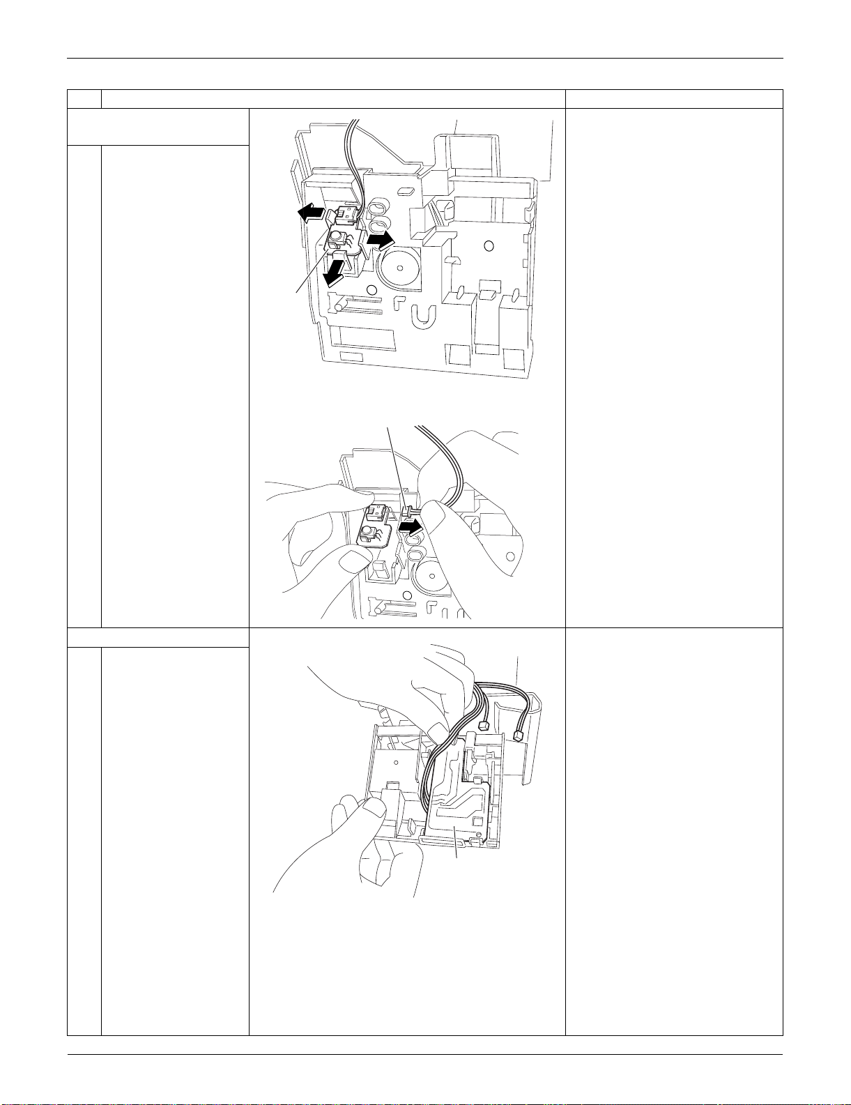
Indoor Unit: FTXS09/12LVJU SiUS091133
173 Removal Procedure
5. Remove the signal
receiver PCB.
1
Unfasten the 3 hooks
and remove the signal
receiver PCB.
2
Disconnect the
connector [S48] from
the signal receiver
PCB.
6. Remove the display PCB. The display PCB is positioned
on the rear side of the signal
receiver unit.
1
The figure shows the
connection of the wire
harness for the display
PCB.
Step
Procedure Points
(R8090)
Signal
receiver
PCB
(R8091)
[S48]
(R8094)
Display PCB
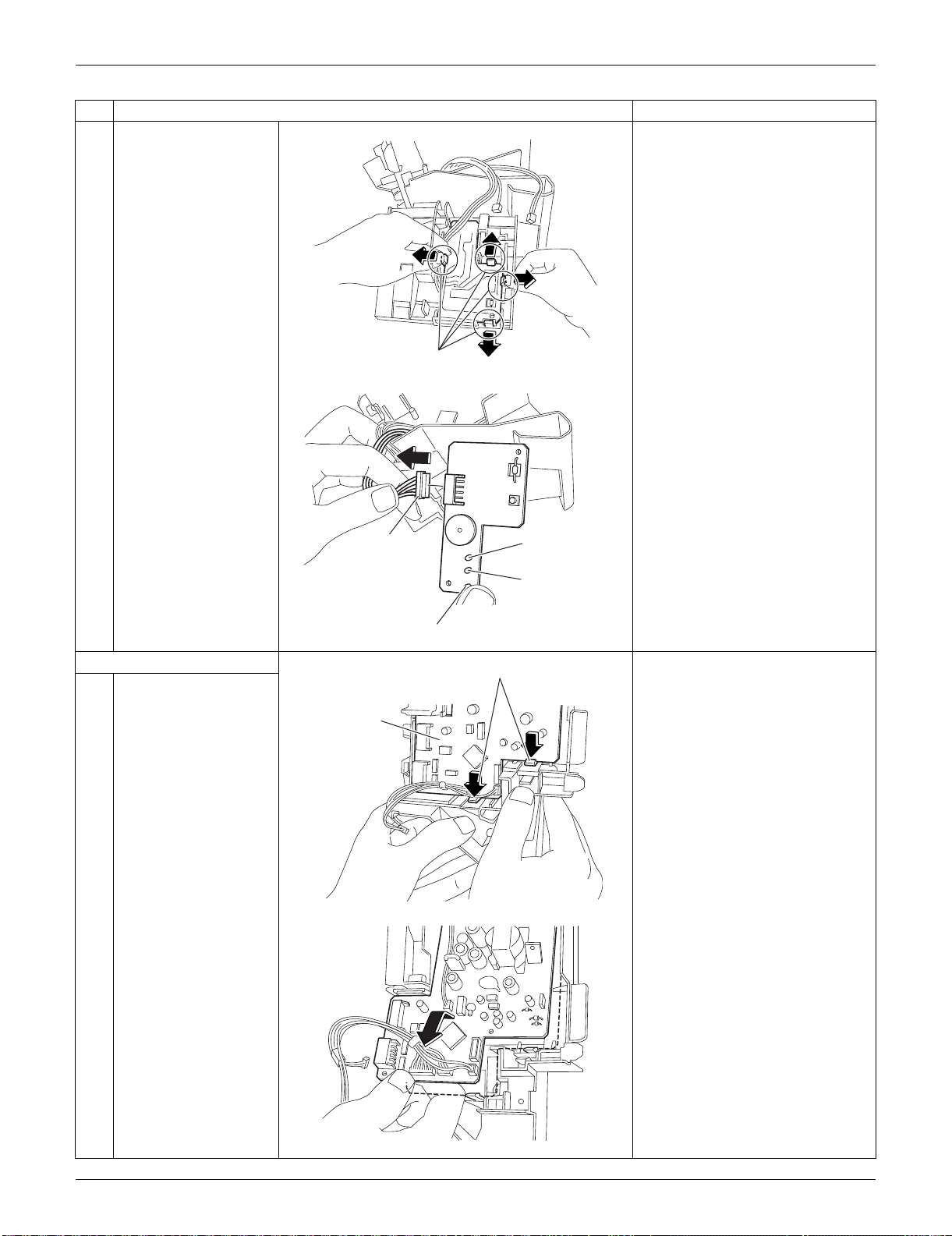
SiUS091133 Indoor Unit: FTXS09/12LVJU
Removal Procedure 174
2
Unfasten the 4 hooks
and remove the display
PCB.
3
Disconnect the
connector [S49] from
the display PCB.
7. Remove the control PCB.
1
Unfasten the lower 2
hooks of the control
PCB.
2
Lift up the bottom of the
control PCB and pull it
out.
The control PCB is also fixed by
2 upper hooks. When
reassembling, be sure to fit all
the 4 hooks.
Step
Procedure Points
(R10318)
Hook
(R8096)
LED 3 (Green)
LED 1 (Green)
[S49]
LED 2 (Yellow)
(R8097)
Hook
Control PCB
(R8098)
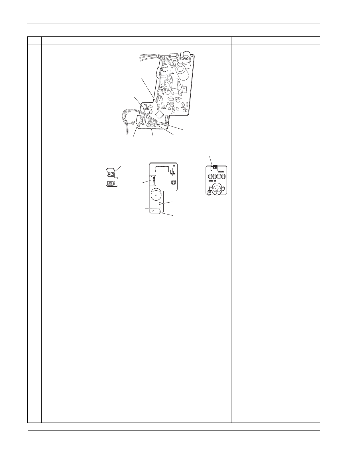
Indoor Unit: FTXS09/12LVJU SiUS091133
175 Removal Procedure
3
The figures show the
names of the PCB
component parts.
[S1]: DC fan motor
[S25]: INTELLIGENT EYE
sensor PCB
[S26]: control PCB
[S32]: indoor heat exchanger
thermistor
[S41]: swing motors
[S46]: display PCB
[S47]: signal receiver PCB
[S48] [S49]: control PCB
Refer to page 14, 15 for detail.
Step
Procedure Points
(R16970)
[S32]
[S1]
[S47]
[S25]
[S46]
[S41]
(R8100)
[S48]
[S49]
[S26]
LED2
(Yellow)
LED3
(Green)
LED1
(Green)
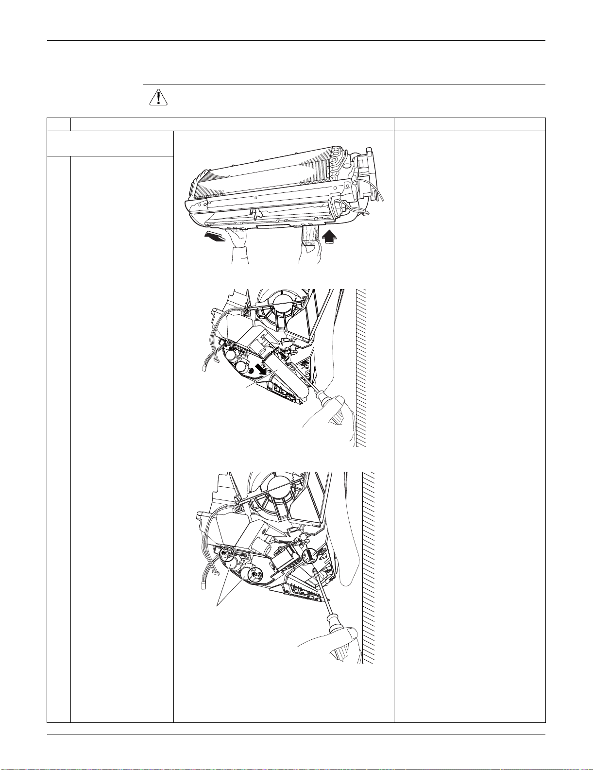
SiUS091133 Indoor Unit: FTXS09/12LVJU
Removal Procedure 176
1.7 Removal of Swing Motors
Procedure Warning Be sure to wait for 10 minutes or more after turning off all power
supplies before disassembling work.
Step
Procedure Points
1. Remove the swing motor
for vertical blades.
1
Lift the indoor unit with
a wooden base.
2
Remove the screw
behind the drain hose,
and disconnect the
drain hose.
3
Remove the screw at
the rear, and remove
the screws on the right
and the left side of the
swing motors for
horizontal blades.
(R10323)
(R10329)
Drain hose
(R13748)
Swing motor for
horizontal blades
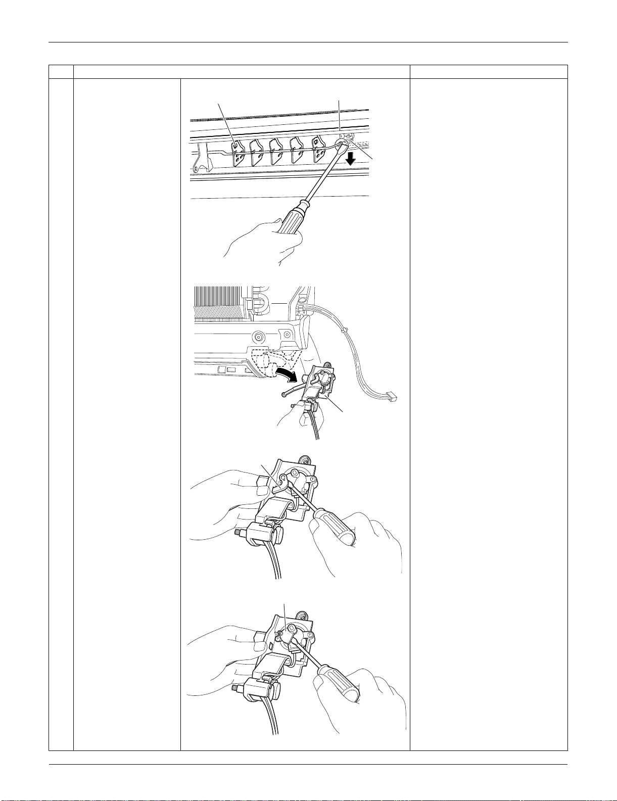
Indoor Unit: FTXS09/12LVJU SiUS091133
177 Removal Procedure
4
Detach the pivot from
the interlock shaft for
vertical blades with a
flat screwdriver.
5
Remove the swing
motor unit.
6
Detach the interlock
shaft from the swing
motor with a flat
screwdriver.
7
Remove the vertical
blade interlock with a
flat screwdriver.
Step
Procedure Points
(R13092)
Interlock
shaft
Pivot
Vertical blade
(R8126)
Swing motor unit
(R8127)
Interlock shaft
(R10331)
Vertical blade interlock
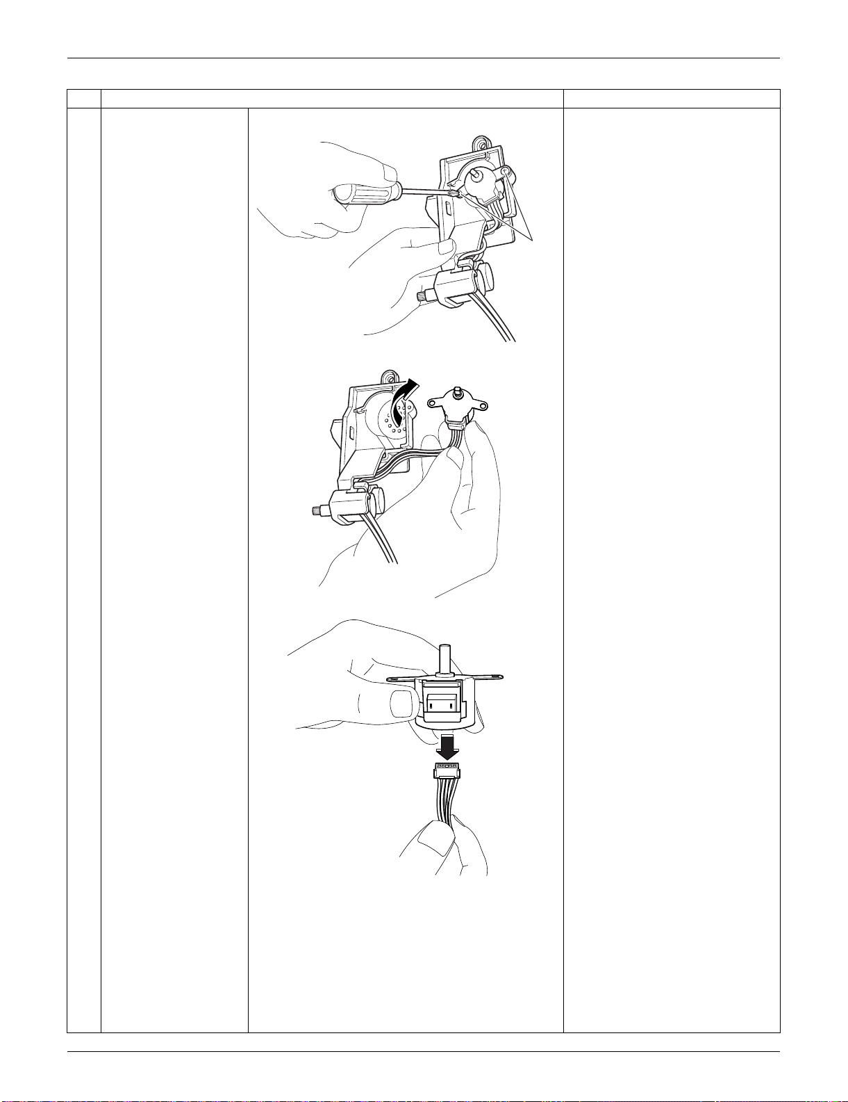
SiUS091133 Indoor Unit: FTXS09/12LVJU
Removal Procedure 178
8
Remove the 2 screws.
9
Remove the swing
motor for vertical
blades.
10
Disconnect the
connector.
Connector: green
Step
Procedure Points
(R13573)
Screw
(R10333)
(R10334)
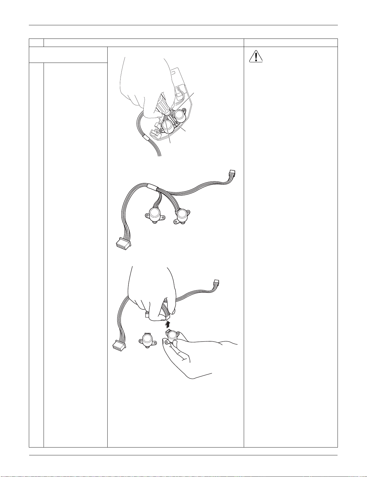
Indoor Unit: FTXS09/12LVJU SiUS091133
179 Removal Procedure
2. Remove the swing motors
for horizontal blades. Caution
When reassembling, do not
confuse the installing order of
the 2 motors and the colors of
the connectors.
If you set the connectors or
motors opposite, the horizontal
blades do not move smoothly or
noise may be heard.
(1) Set the swing motor for the
upper blade first.
(connector: white)
(2) Then, set the swing motor for
the lower blade.
(connector: red)
(3) Fix both swing motors with a
screw.
1
Remove the screw and
remove the swing
motors for horizontal
blades.
2
Disconnect the
harnesses from the
motors.
Step
Procedure Points
(R8131)
Connector for
lower blade (red)
Connector for
upper blade (white)
Screw
(R8132)
(R10335)
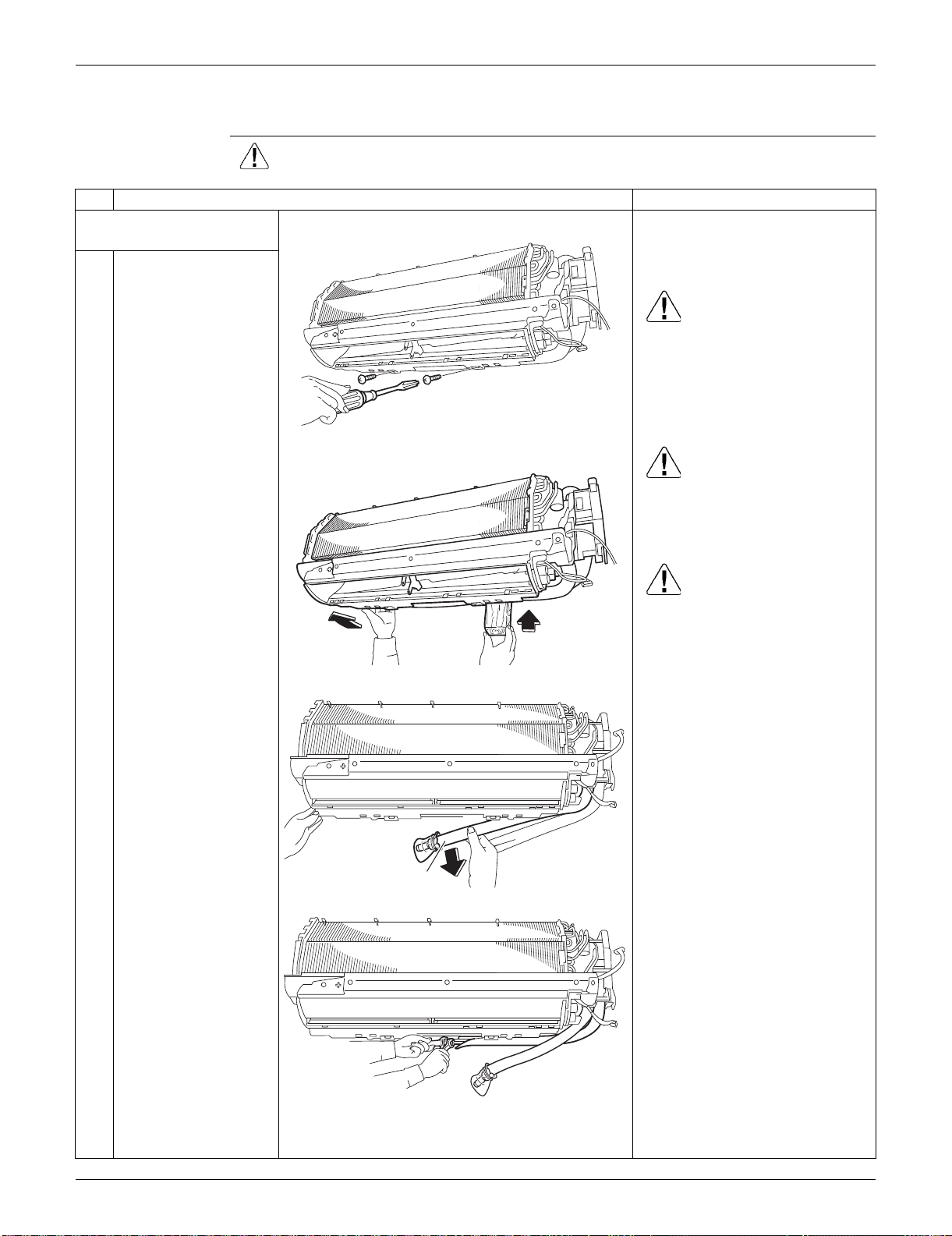
SiUS091133 Indoor Unit: FTXS09/12LVJU
Removal Procedure 180
1.8 Removal of Indoor Heat Exchanger
Procedure Warning Be sure to wait for 10 minutes or more after turning off all power
supplies before disassembling work.
Step
Procedure Points
1. Disconnect the refrigerant
piping.
Preparation
Remove the electrical box
according to the “Removal of
Electrical Box”.
Caution
If the refrigerant leaks, repair the
leakage, then collect all
refrigerant from the unit. After
conducting vacuum drying,
recharge the proper amount of
refrigerant.
Caution
From the viewpoint of global
environment protection, be sure
to use a vacuum pump for air
purging.
Caution
In pump-down work, be sure to
stop the compressor before
disconnecting the refrigerant
piping. If the refrigerant piping is
disconnected with the
compressor operating and the
stop valve open, air may be
sucked in to generate an over-
pressure in refrigeration cycle,
thus resulting in pipe rupture or
accidental injury.
Place a plastic sheet under the
drain pan to prevent from
wetting the floor with remaining
drain.
If the drain hose is embedded in
the wall, disconnect the drain
hose beforehand.
Carry out the removal work with
2 wrenches.
When the pipings are
disconnected, protect both the
openings of pipe and unit from
entering moisture.
1
Remove the screws
which fix the indoor
heat exchanger to the
installation plate.
2
Lift the indoor unit with
a wooden base.
3
Lift up the indoor unit
slightly and pull out the
drain hose. (The
illustration is for the
case of left piping.)
4
Disconnect the gas
piping and the liquid
piping.
(R8103)
(R8104)
(R8101)
Drain hose
(R8105)
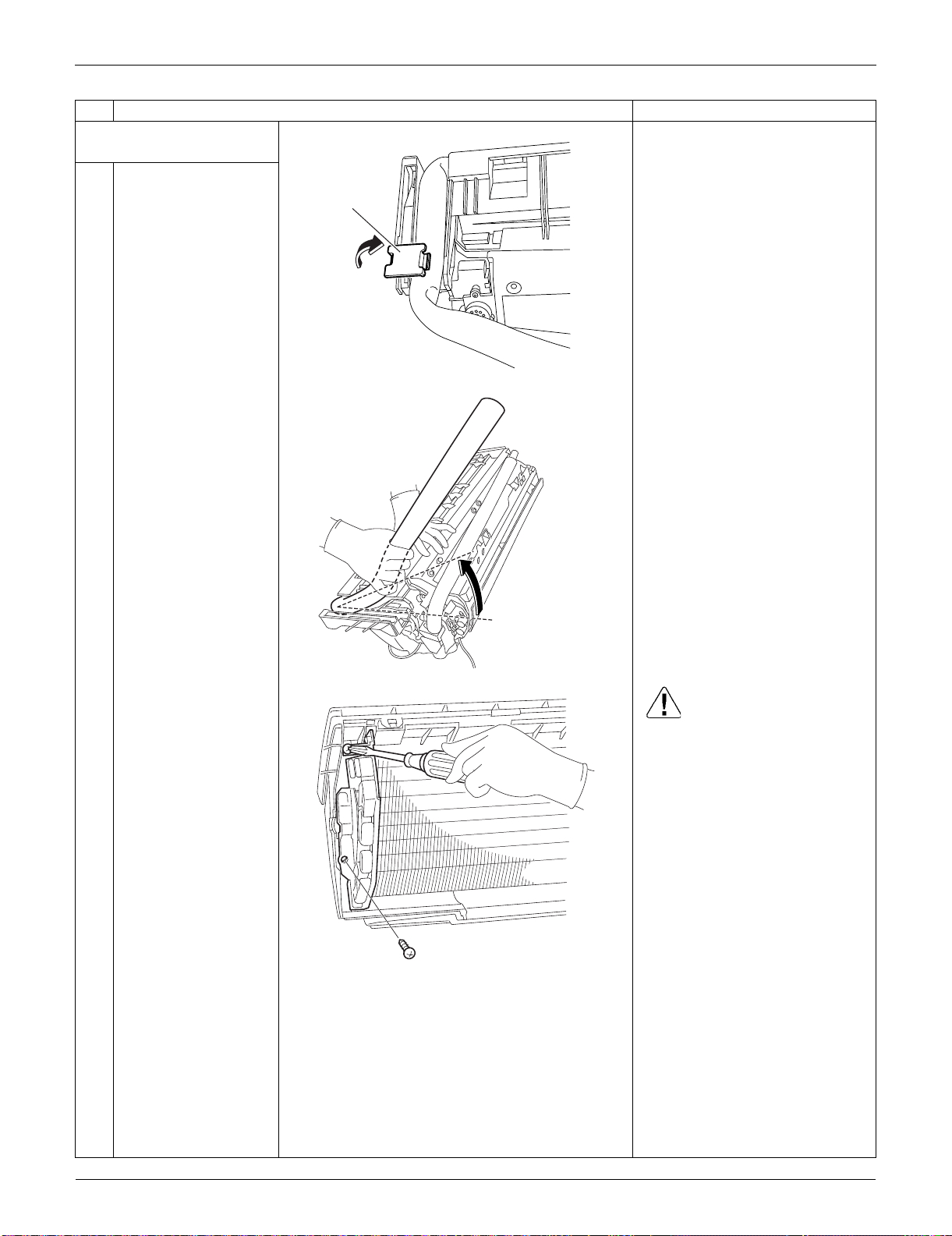
Indoor Unit: FTXS09/12LVJU SiUS091133
181 Removal Procedure
2. Remove the indoor heat
exchanger.
1
Detach the indoor unit
from the installation
plate.
2
Unfasten the hook of
the piping fixture at the
back of the indoor unit.
Remove the piping
fixture.
3
Widen the auxiliary
piping.
4
Remove the 2 screws
on the left side. Caution
When removing or reassembling
the indoor heat exchanger, be
sure to wear gloves or wrap the
indoor heat exchanger with
cloth. (You may be injured by the
fins.)
Step
Procedure Points
(R10622)
Piping
fixture
(R17120)
(R10546)
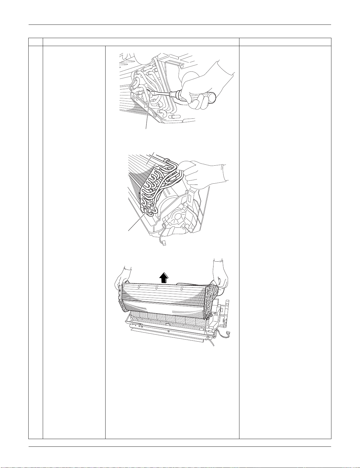
SiUS091133 Indoor Unit: FTXS09/12LVJU
Removal Procedure 182
5
Unfasten the upper
hook on the right side
with a flat screwdriver.
6
After unfastening the
lower hooks, lift up the
indoor heat exchanger
by its right side.
When reassembling the indoor
heat exchanger, make sure that
the right hooks (upper and
lower) are fastened.
7
Remove the indoor
heat exchanger.
Step
Procedure Points
(R13138)
Upper hook
(R13139)
Indoor heat exchanger
Lower hook
(R13140)
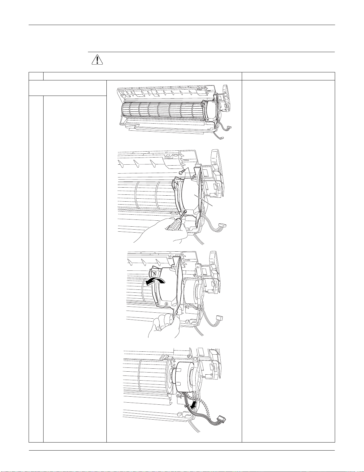
Indoor Unit: FTXS09/12LVJU SiUS091133
183 Removal Procedure
1.9 Removal of Fan Motor
Procedure Warning Be sure to wait for 10 minutes or more after turning off all power
supplies before disassembling work.
Step
Procedure Points
1. Remove the right side
plate.
Preparation
Remove the indoor heat
exchanger according to the
“Removal of Indoor Heat
Exchanger”.
1
Remove the 2 screws
and remove the right
side plate.
2
Release the fan motor
wire harness from the
hook.
(R8112)
(R13502)
Right side
plate
(R8114)
(R8115)
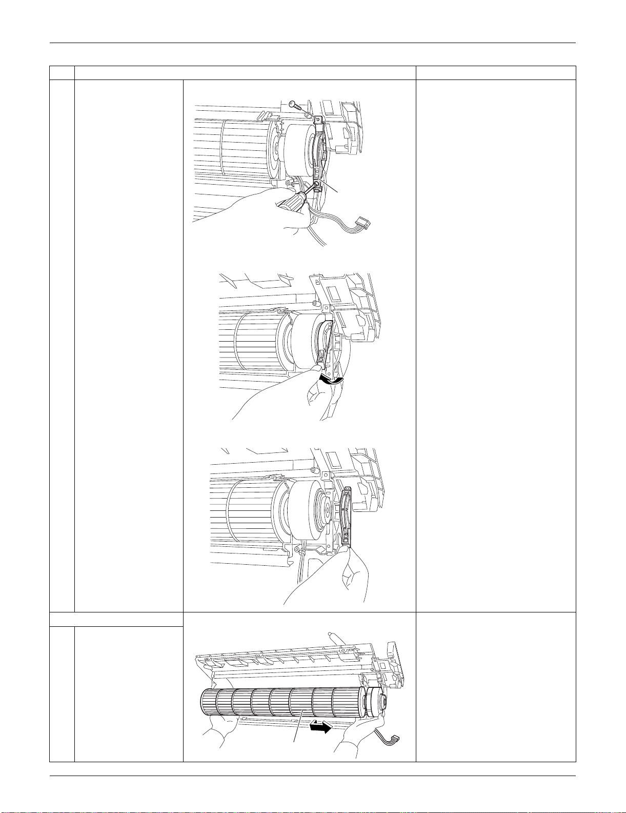
SiUS091133 Indoor Unit: FTXS09/12LVJU
Removal Procedure 184
3
Remove the 2 screws
of the fan motor fixing
plate.
4
Unfasten the hook of
the fan motor fixing
plate and remove the
plate.
2. Remove the fan motor.
1
Dislocate the fan rotor
by sliding it to the right.
Step
Procedure Points
(R8116)
Fan motor fixing plate
(R8117)
(R8118)
(R8119)
Fan rotor
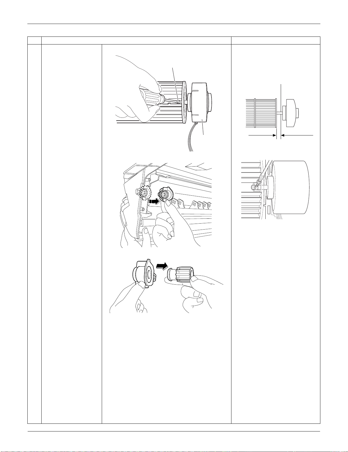
Indoor Unit: FTXS09/12LVJU SiUS091133
185 Removal Procedure
2
Loosen the lock screw
and remove the fan
motor.
When reassembling the fan
motor and the fan rotor, provide
as much as 5 mm (0.2 inch) of
play between the side face of
the rotor and the bottom frame.
(1) Insert the fan motor with approx.
5 mm (0.2 inch) left.
(2) Tighten the screw until it stops.
Then give the screw one more
turn.
(3) Rotate the fan rotor and confirm
the fan motor and the fan rotor
are installed appropriately.
(4) Tighten the screw completely if
appropriate.
(5) If not appropriate, go back to
(1).
3
Press the bearing
ASSY from outside.
4
Remove the bearing.
Step
Procedure Points
(R8120)
Lock screw
Fan motor
5 mm (0.2 inch)
Side face of rotor
(R2808)
Side face of
bottom frame
(R9582)
(R8121)
(R8122)
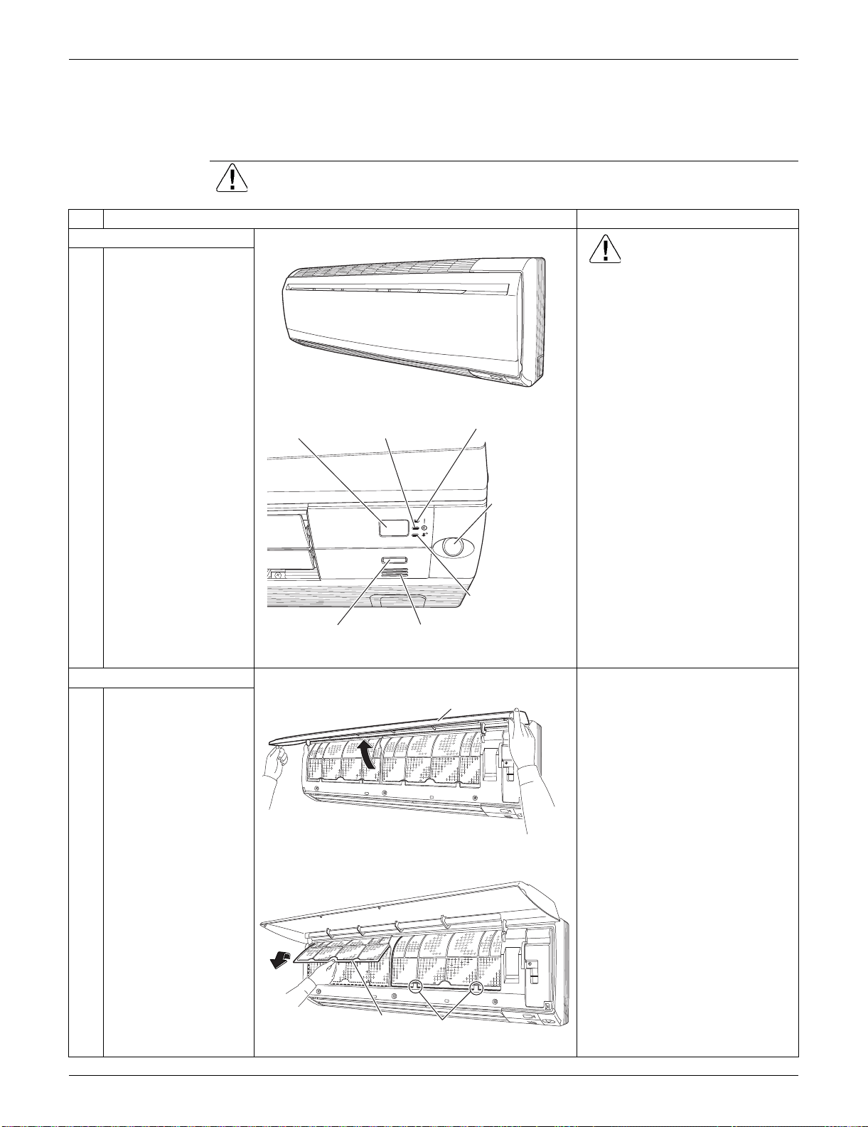
SiUS091133 Indoor Unit: FTXS15/18/24LVJU
Removal Procedure 186
2. Indoor Unit: FTXS15/18/24LVJU
2.1 Removal of Air Filters / Front Panel
Procedure Warning Be sure to wait for 10 minutes or more after turning off all power supplies
before disassembling work.
Step
Procedure Points
1. Appearance features
Warning
Dangerous: High voltage
A high voltage is applied to all
the electric circuits of this
product including thermistors.
When the signal receiver
catches a signal from the
remote controller, the receiving
tone sounds and the operation
lamp blinks immediately to
confirm the signal reception.
When the [ON/OFF] button is
kept pressed for 5 seconds, the
forced cooling operation is
performed for about 15 minutes.
2. Remove the air filters.
1
Open the front panel to
the position where it
stops.
2
Slightly push up the
center knob of the air
filter and unfasten the
hooks.
The 2 filters are
interchangeable.
The air filter can be set easily by
inserting it along the guides.
Insert the air filter with the
"FRONT" mark faced up.
Be sure to insert the hooks (at 2
lower positions) when
reassembling the air filter.
3
Pull out the air filter
downward and remove
it.
(R16259)
ON/OFF
(R16682)
Operation lamp
TIMER lampSignal receiver
Room temperature thermistor[ON/OFF] button
INTELLIGENT
EYE sensor
INTELLIGENT
EYE lamp
Front Panel
(R16683)
(R16975)
Air filter
Hook
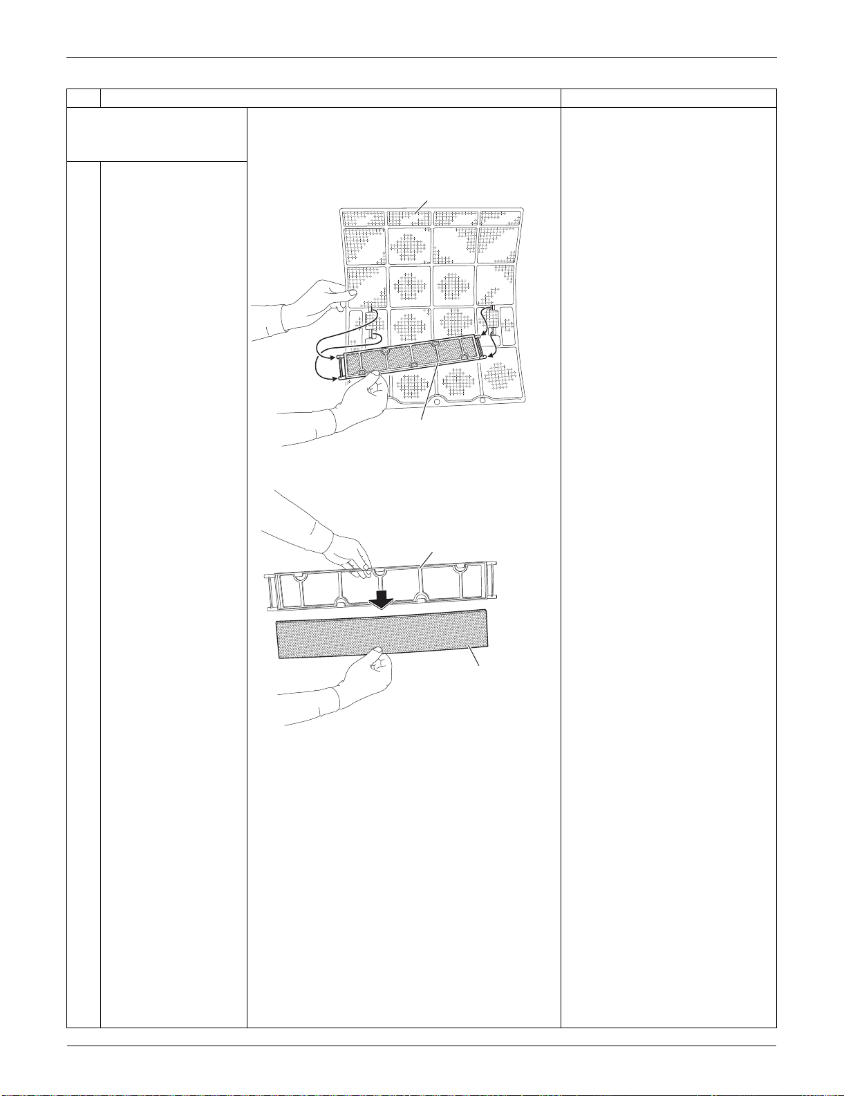
Indoor Unit: FTXS15/18/24LVJU SiUS091133
187 Removal Procedure
3. Remove the Titanium
apatite photocatalytic air-
purifying filters.
1
Remove the Titanium
apatite photocatalytic
air-purifying filter ASSY
by unfastening the
projections from the
back of the air filter
frame.
The right and left filters are
interchangeable.
2
Remove the Titanium
apatite photocatalytic
air-purifying filter from
its frame.
Step
Procedure Points
(R16262)
Air filter
Titanium apatite photocatalytic
air-purifying filter ASSY
(R9478)
Frame
Titanium apatite photocatalytic
air-purifying filter
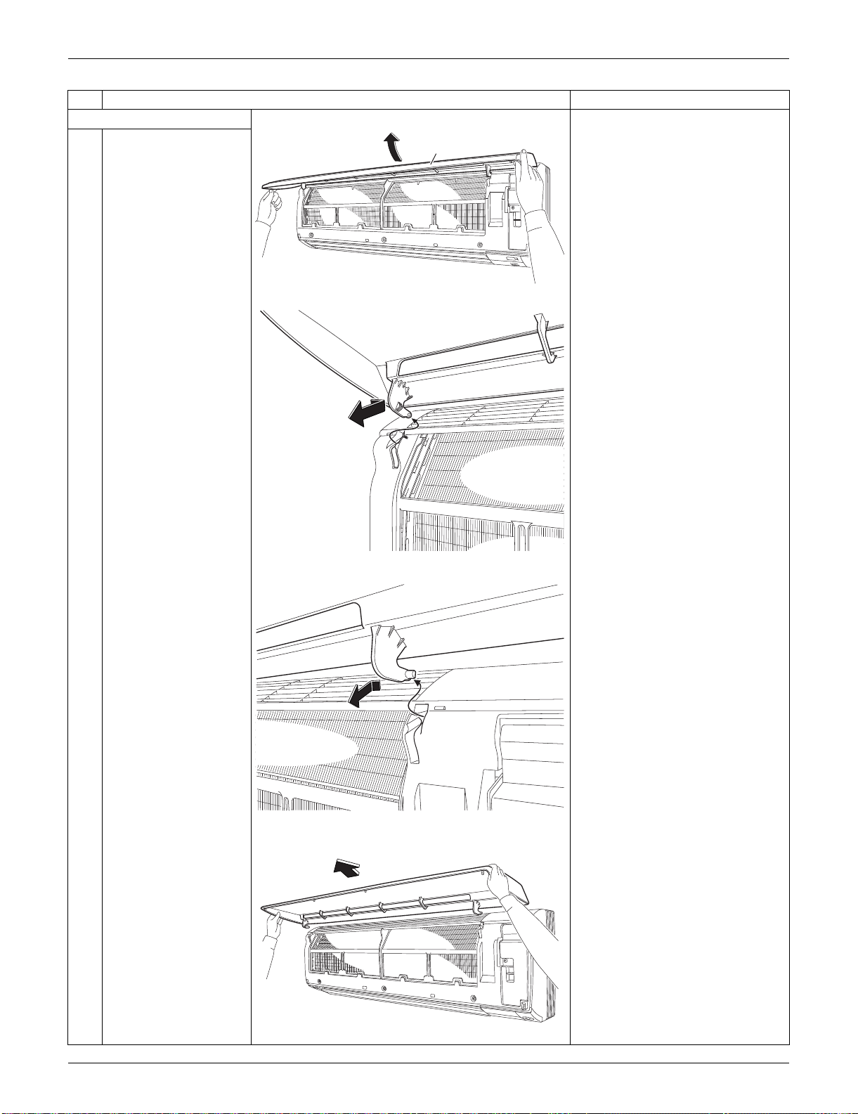
SiUS091133 Indoor Unit: FTXS15/18/24LVJU
Removal Procedure 188
4. Remove the front panel.
1
While opening the front
panel further than it
stops, release both the
shafts.
Slide the front panel from side to
side to release each shaft.
Align the right and left shafts
with grooves in turn and insert
them to the end when
reassembling.
2
Remove the front
panel.
Step
Procedure Points
(R16456)
Front Panel
(R9480)
(R9481)
(R16684)
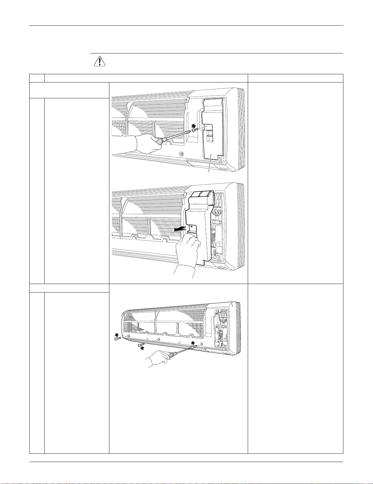
Indoor Unit: FTXS15/18/24LVJU SiUS091133
189 Removal Procedure
2.2 Removal of Front Grille
Procedure Warning Be sure to wait for 10 minutes or more after turning off all power supplies
before disassembling work.
Step
Procedure Points
1. Remove the service
cover.
1
Remove the screw and
remove the service
cover.
You can remove the front grille
without detaching the service
cover.
2. Remove the front grille.
1
Remove the 3 screws
of the front grille.
Refer to the removal procedure
in a reverse way when
reassembling.
(R9483)
Service cover
(R9484)
(R16685)
Front grille
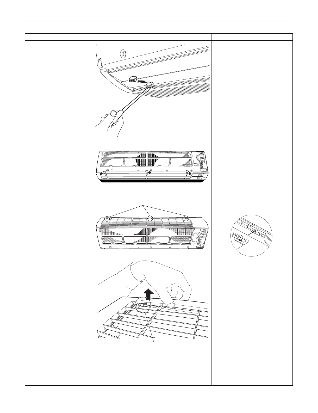
SiUS091133 Indoor Unit: FTXS15/18/24LVJU
Removal Procedure 190
2
Remove the screw
caps with a flat
screwdriver.
3
Remove the lower 3
screws.
4
Unfasten the 3 hooks
on the top of the front
grille.
The convex marks (...) on the
front panel indicate the position
of the hooks.
Step
Procedure Points
(R16266)
(R16686)
(R16511)
Hook
(R9487)
Hook
(R12715)
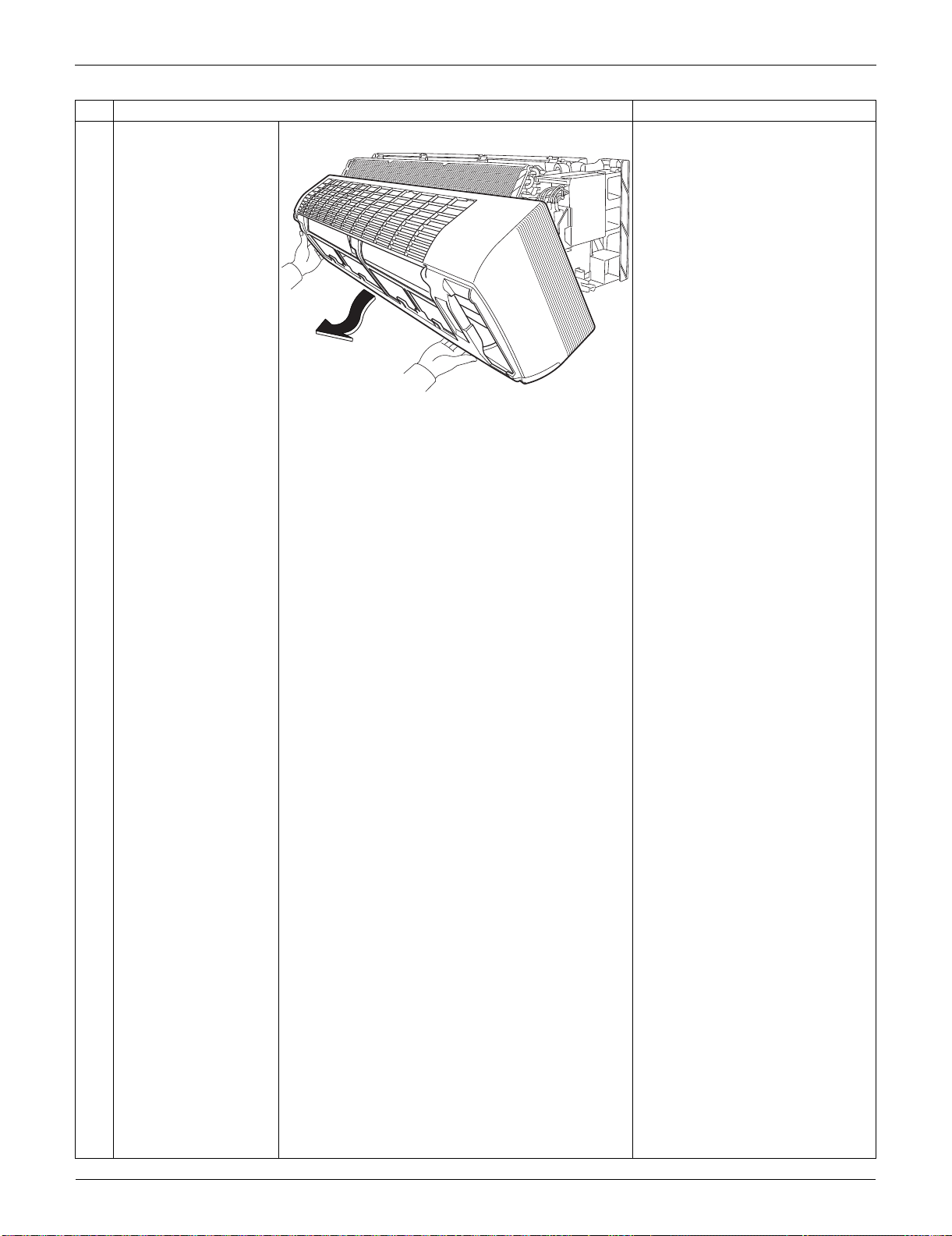
Indoor Unit: FTXS15/18/24LVJU SiUS091133
191 Removal Procedure
5
Pull the upper part of
the front grille out and
lift the lower part up,
and then remove the
front grille.
When reassembling, make sure
that all the 3 hooks are fastened
as they were.
Step
Procedure Points
(R16269)
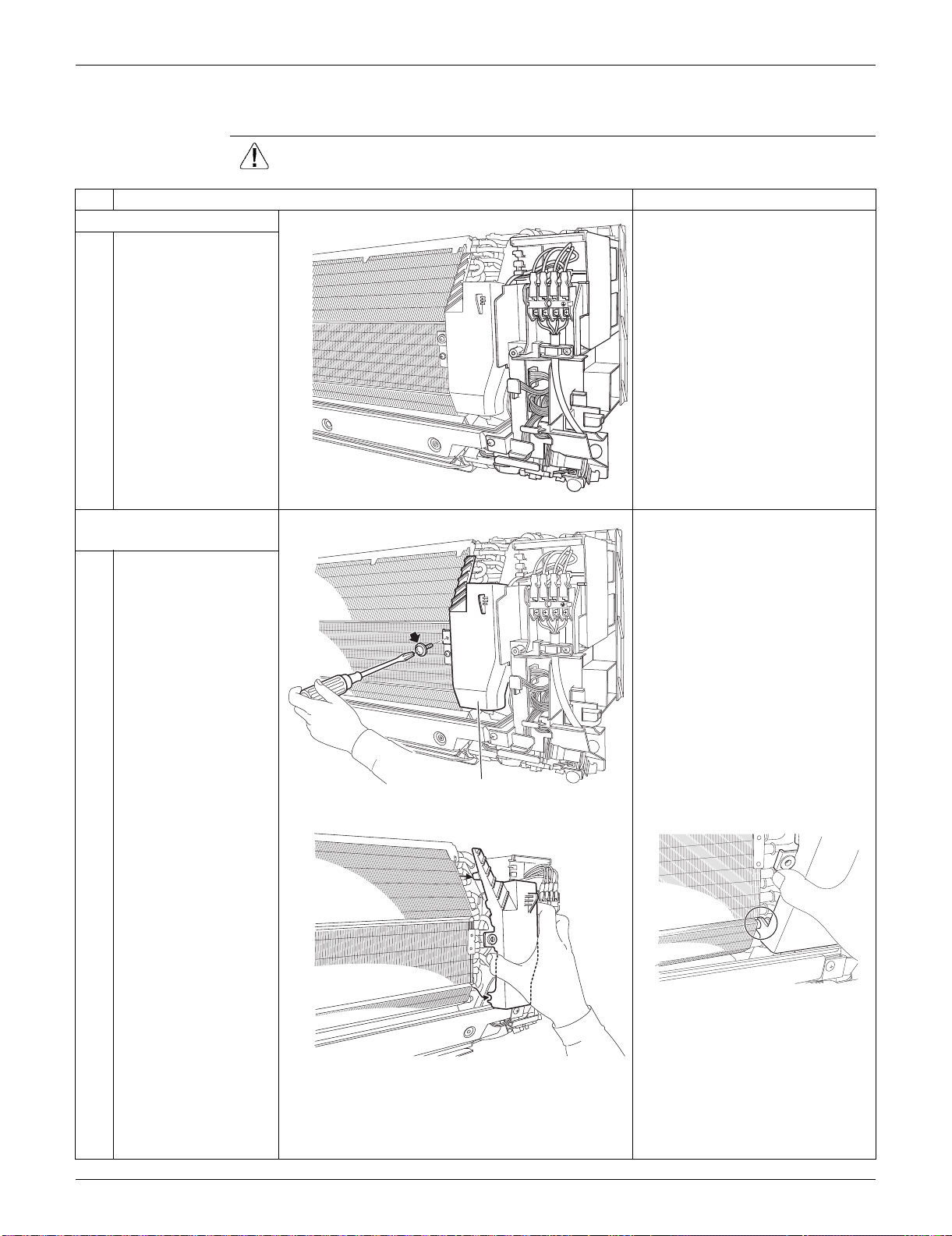
SiUS091133 Indoor Unit: FTXS15/18/24LVJU
Removal Procedure 192
2.3 Removal of Electrical Box
Procedure Warning Be sure to wait for 10 minutes or more after turning off all power supplies
before disassembling work.
Step
Procedure Points
1. Layout of the parts
Preparation
Remove the front grille
according to the “Removal of
Front Grille.”
2. Remove the drip proof
plate. The shape of the drip proof plate
differs by the model.
1
Remove the screw.
2
Remove the drip proof
plate from the indoor
heat exchanger.
When reassembling, fit the hook
to the indoor heat exchanger.
1
2
3
(R16270)
1
2
3
(R16271)
Drip proof plate
(R16272)
(R16273)

Indoor Unit: FTXS15/18/24LVJU SiUS091133
193 Removal Procedure
3. Release the ground wire
and the indoor heat
exchanger thermistor.
1
Cut the clamp
2
Pull out and release the
ground wire.
3
Pull out the indoor heat
exchanger thermistor.
The position of the indoor heat
exchanger thermistor is slightly
different depending on the
model.
Be careful not to lose the clip of
the thermistor.
Step
Procedure Points
(R16274)
(R16275)
(R16276)
Clip
(R11268)
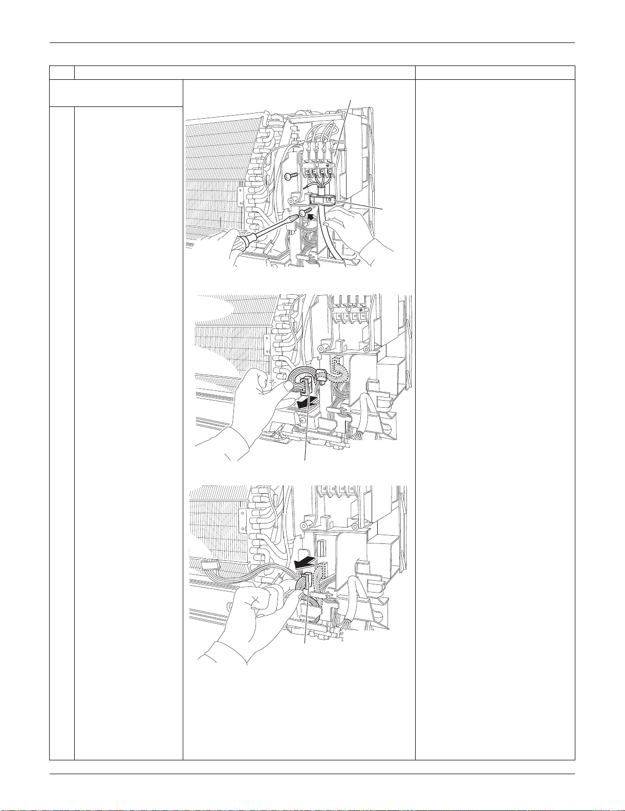
SiUS091133 Indoor Unit: FTXS15/18/24LVJU
Removal Procedure 194
4. Remove the electrical
box.
1
Remove the 4 screws
and disconnect the
connection wires on the
terminal board.
Remove the screw and
remove the wire
retainer.
2
Disconnect the
connector for the fan
motor [S1] and release
the harness from the
hook.
3
Disconnect the
connector for the swing
motors [S41].
Step
Procedure Points
1
2
3
(R16277)
Terminal board
Wire
retainer
1
2
3
(R16278)
[S1]
(R16279)
[S41]
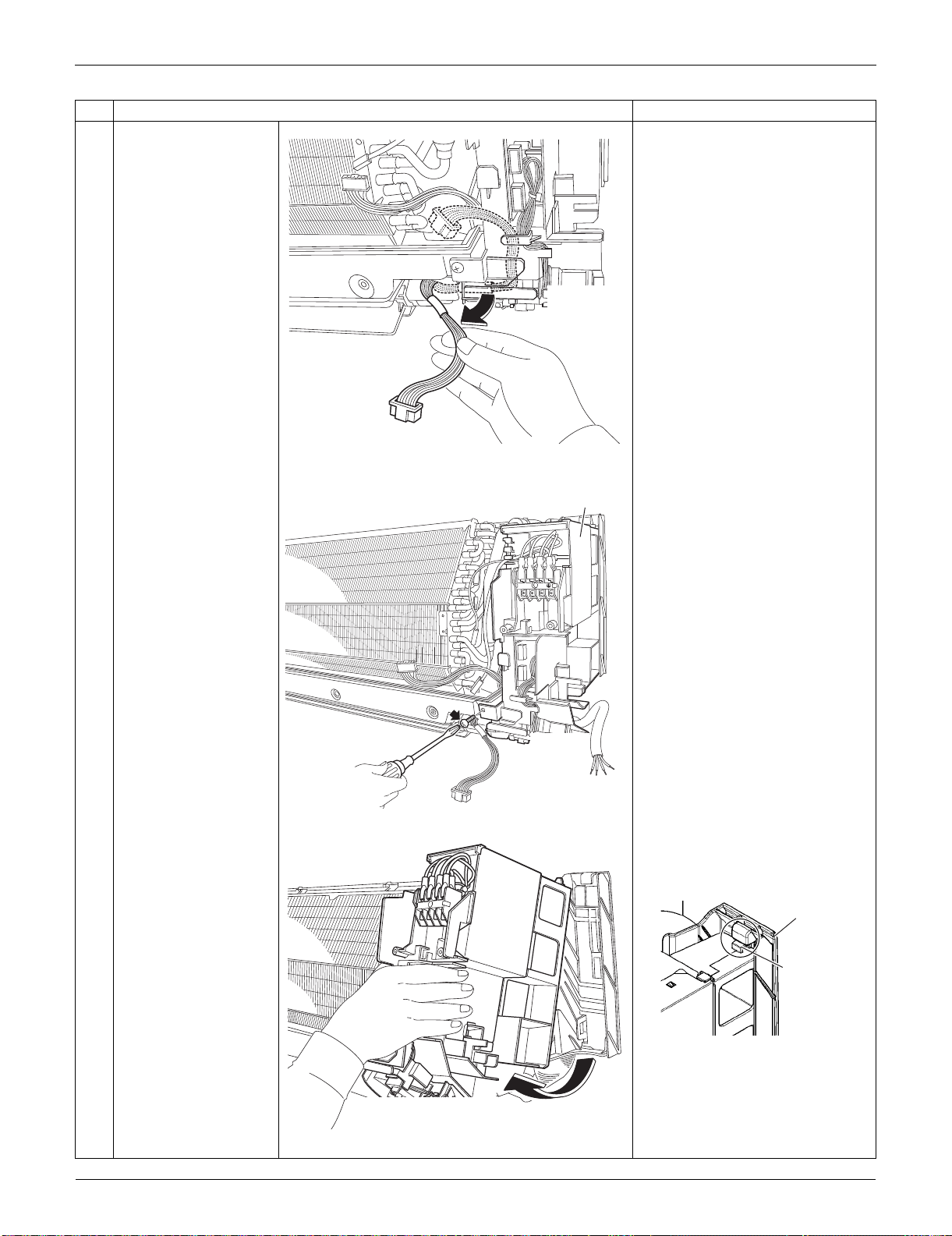
Indoor Unit: FTXS15/18/24LVJU SiUS091133
195 Removal Procedure
4
Release the harness
from the hooks.
5
Remove the screw of
the electrical box.
6
Lift up the electrical box
from the bottom frame
and remove it.
Fit the back hook of the
electrical box to the bottom
frame when reassembling.
Step
Procedure Points
(R16280)
1
2
3
(R16281)
Electrical box
(R16282)
(R9647)
Bottom frame
Hook
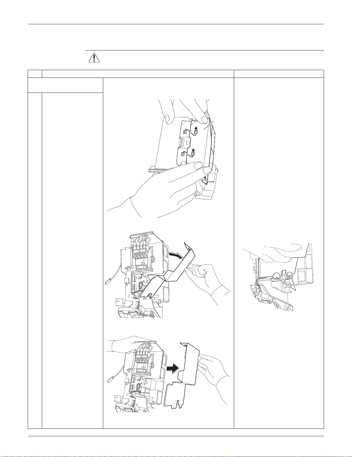
SiUS091133 Indoor Unit: FTXS15/18/24LVJU
Removal Procedure 196
2.4 Removal of PCBs
Procedure Warning Be sure to wait for 10 minutes or more after turning off all power supplies
before disassembling work.
Step
Procedure Points
1. Remove the signal
receiver PCB.
1
Unfasten the hooks of
the shield plate.
Preparation
Remove the electrical box
according to the “Removal of
Electrical Box.”
2
Open the shield plate. The shield plate has 2 hooks at
the lower part also.
3
Remove the shield
plate.
(R9506)
Shield
plate
(R16283)
(R16498)
Hook
(R16284)
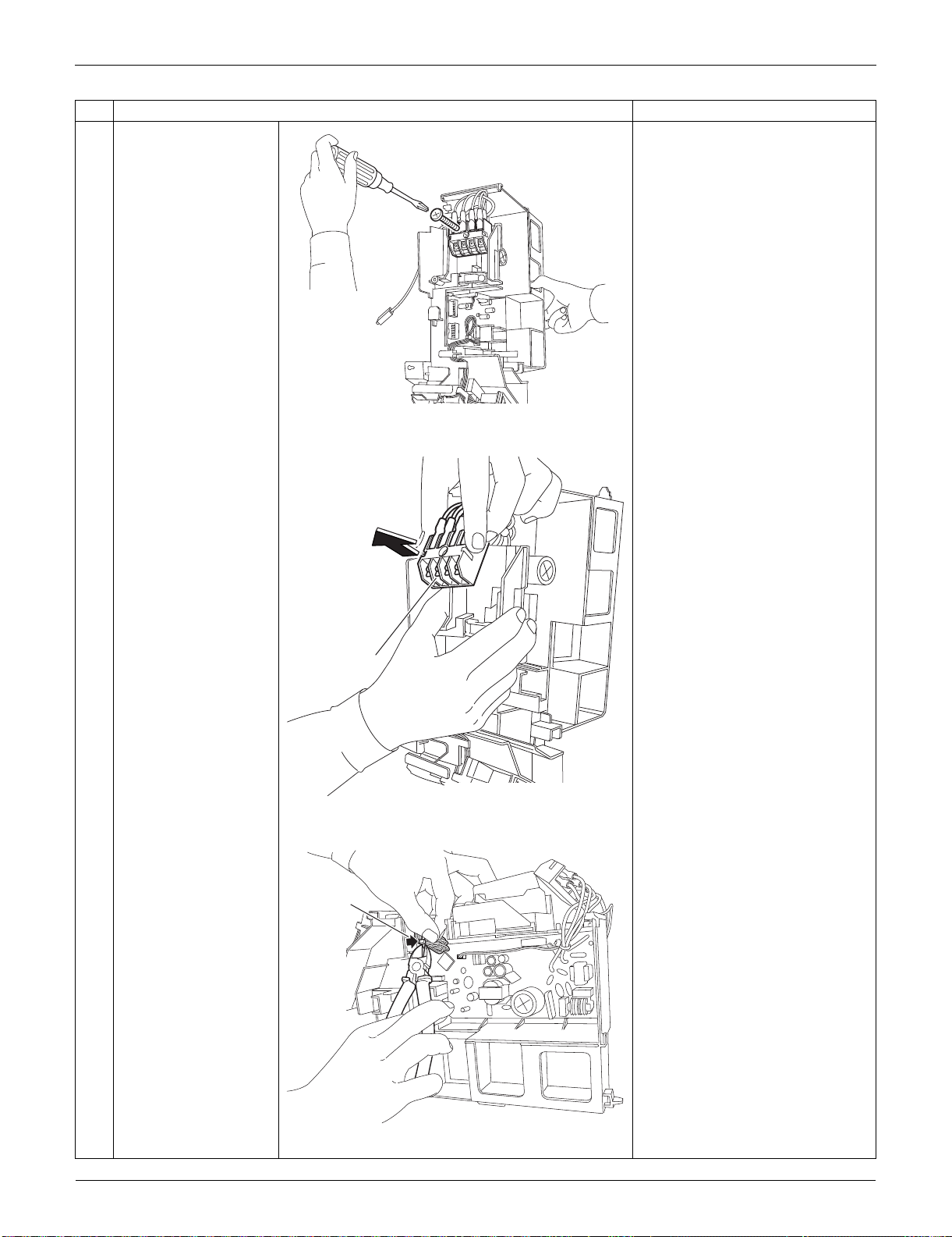
Indoor Unit: FTXS15/18/24LVJU SiUS091133
197 Removal Procedure
4
Remove the screw of
the terminal board.
5
Remove the terminal
board.
(1 hook at the back)
6
Cut the clamp.
Step
Procedure Points
(R16285)
(R16286)
Terminal board
(R16971)
Clamp
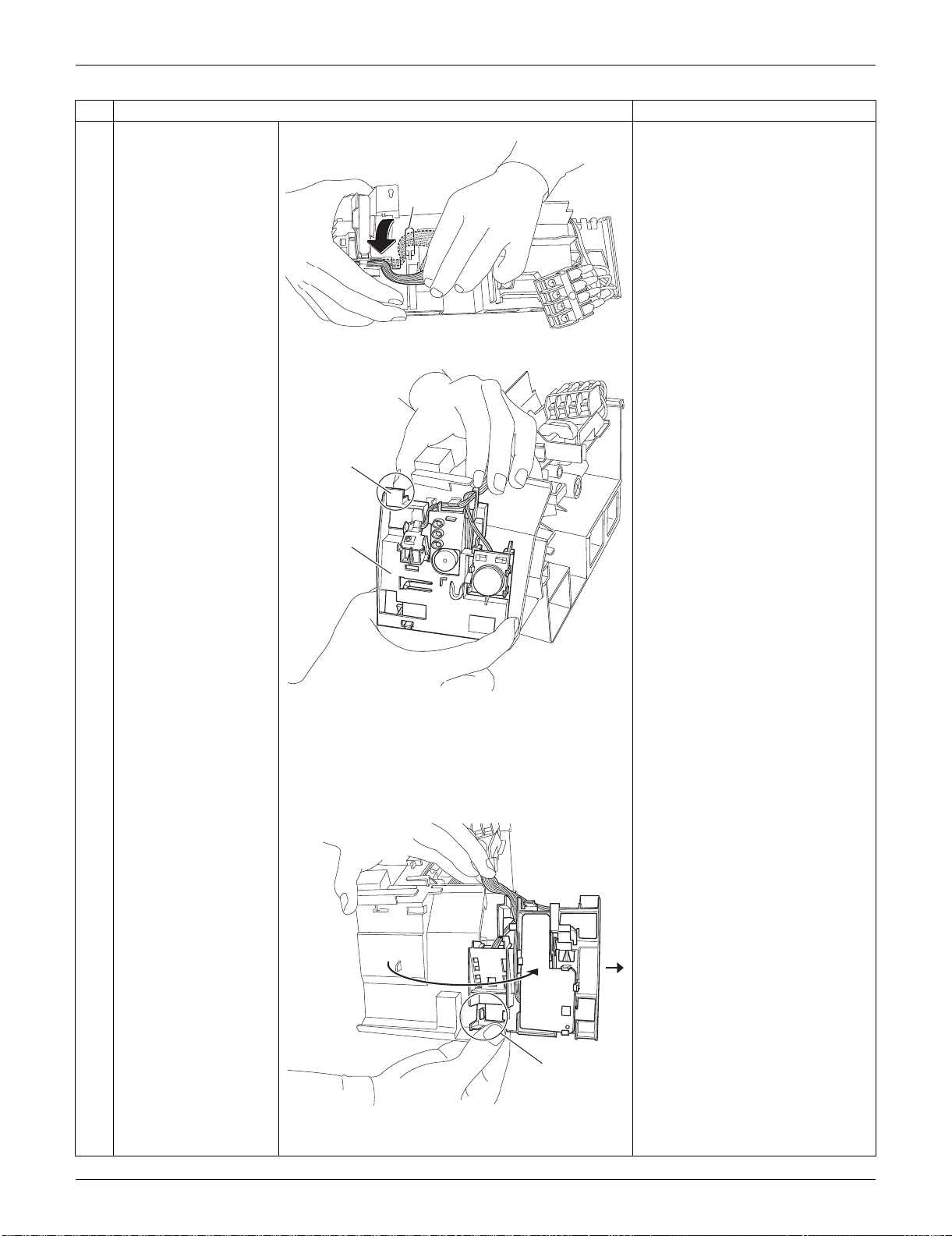
SiUS091133 Indoor Unit: FTXS15/18/24LVJU
Removal Procedure 198
7
Release the harness
from the hook.
When reassembling, make sure
to hook the harness.
8
Push and unfasten the
hook of the signal
receiver unit.
9
Open the signal
receiver unit.
Unfasten the hook and
remove the signal
receiver unit.
Step
Procedure Points
(R9514)
Hook
(R13518)
Hook
Signal
receiver
unit
(R9516)
Hook
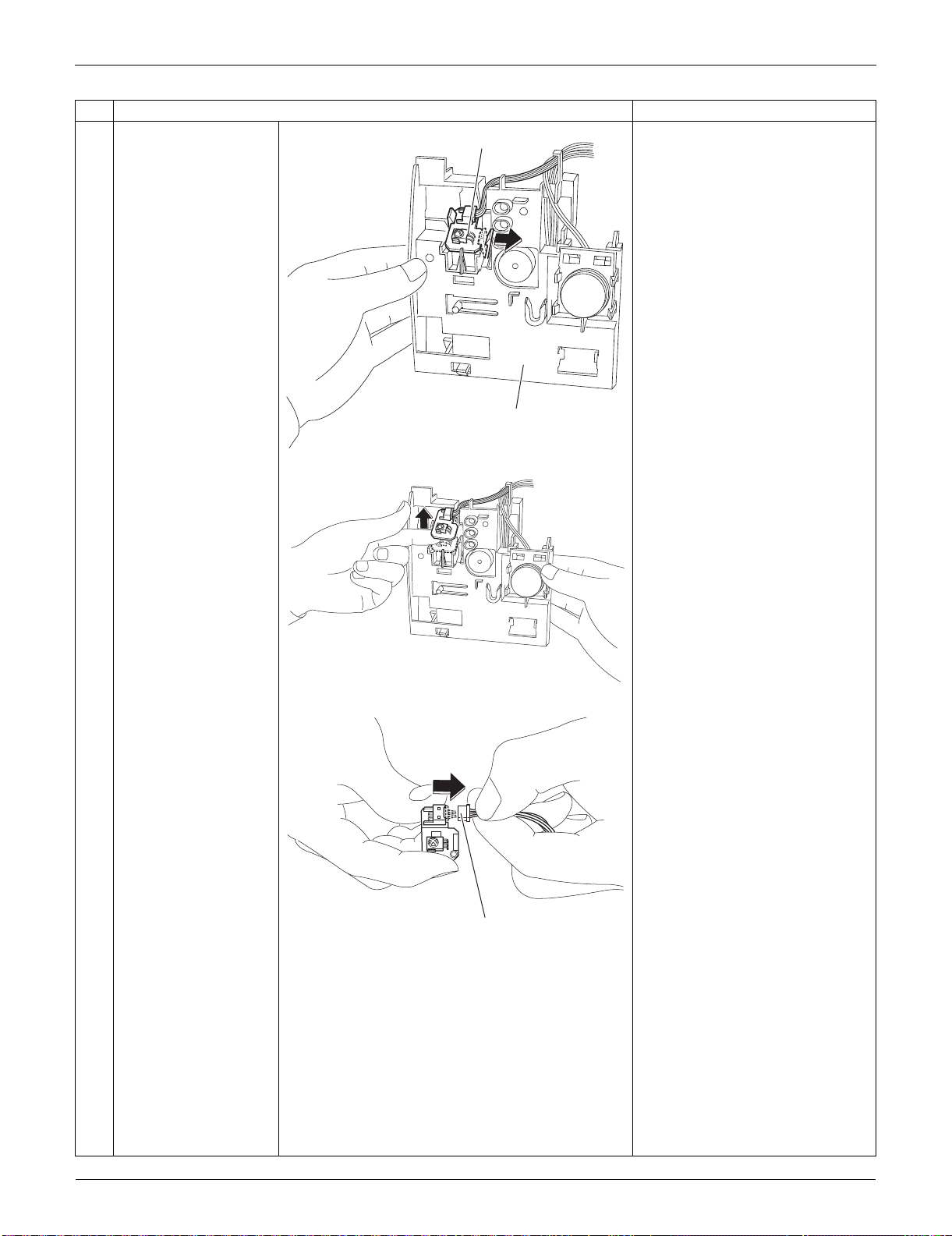
Indoor Unit: FTXS15/18/24LVJU SiUS091133
199 Removal Procedure
10
Unfasten the hook on
the right of the signal
receiver PCB.
(Then the signal
receiver PCB is lifted
up.)
11
Remove the signal
receiver PCB.
12
Disconnect the
connector.
[S48] : to control PCB
Step
Procedure Points
(R13519)
Signal receiver PCB
Signal receiver unit
(R9521)
(R9522)
[S48]
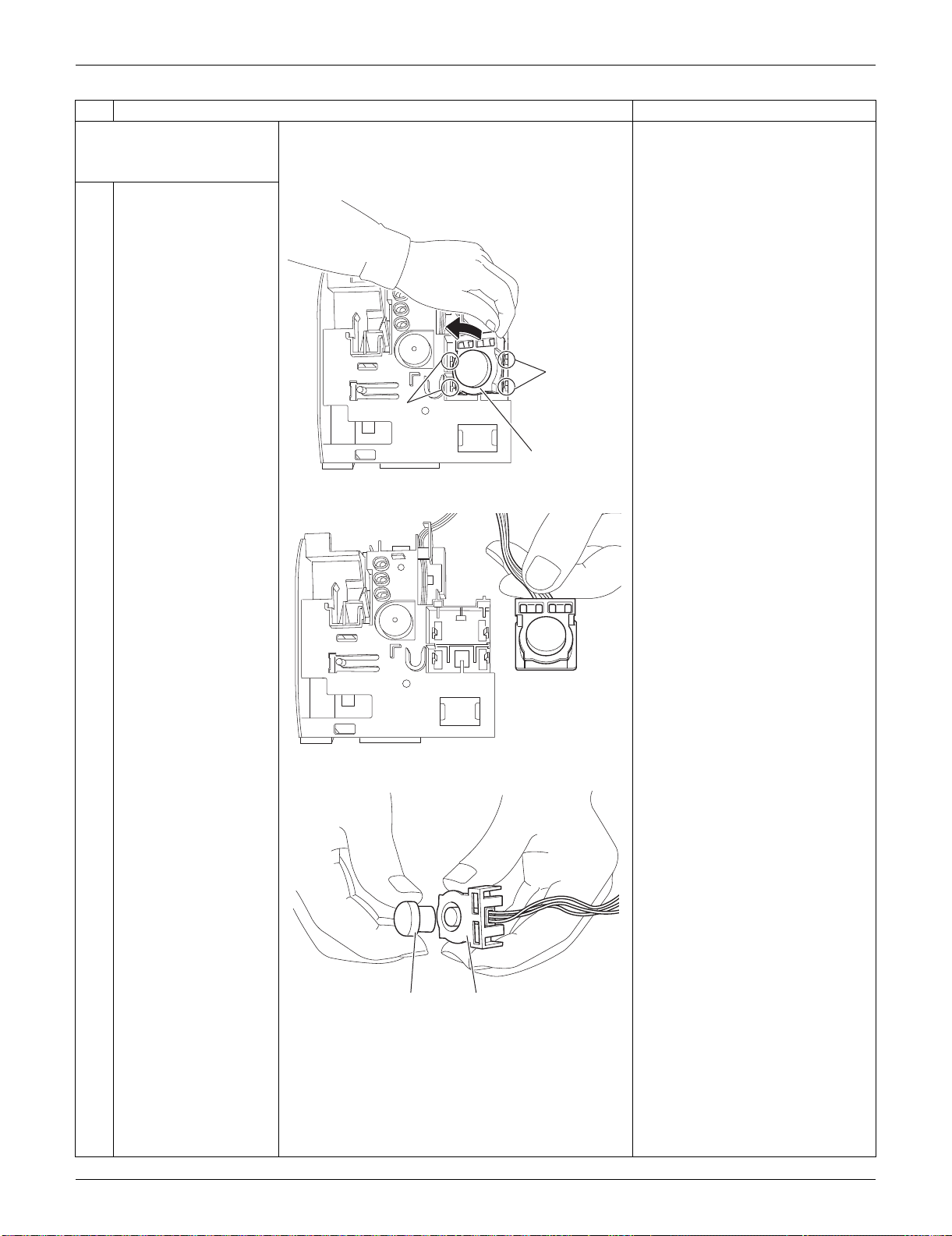
SiUS091133 Indoor Unit: FTXS15/18/24LVJU
Removal Procedure 200
2. Remove the
INTELLIGENT EYE
sensor PCB.
1
Unfasten the 2 hooks
on the right and then
the 2 hooks on the left.
Remove the
INTELLIGENT EYE
sensor ASSY.
2
Remove the sensor
from the shield plate.
When reassembling, set the
sensor at the position where it
“clicks”. Otherwise, the sensor is
not completely set.
Step
Procedure Points
(R9523)
Hook
Hook
INTELLIGENT EYE
sensor ASSY
(R9524)
(R9525)
Sensor Shield plate
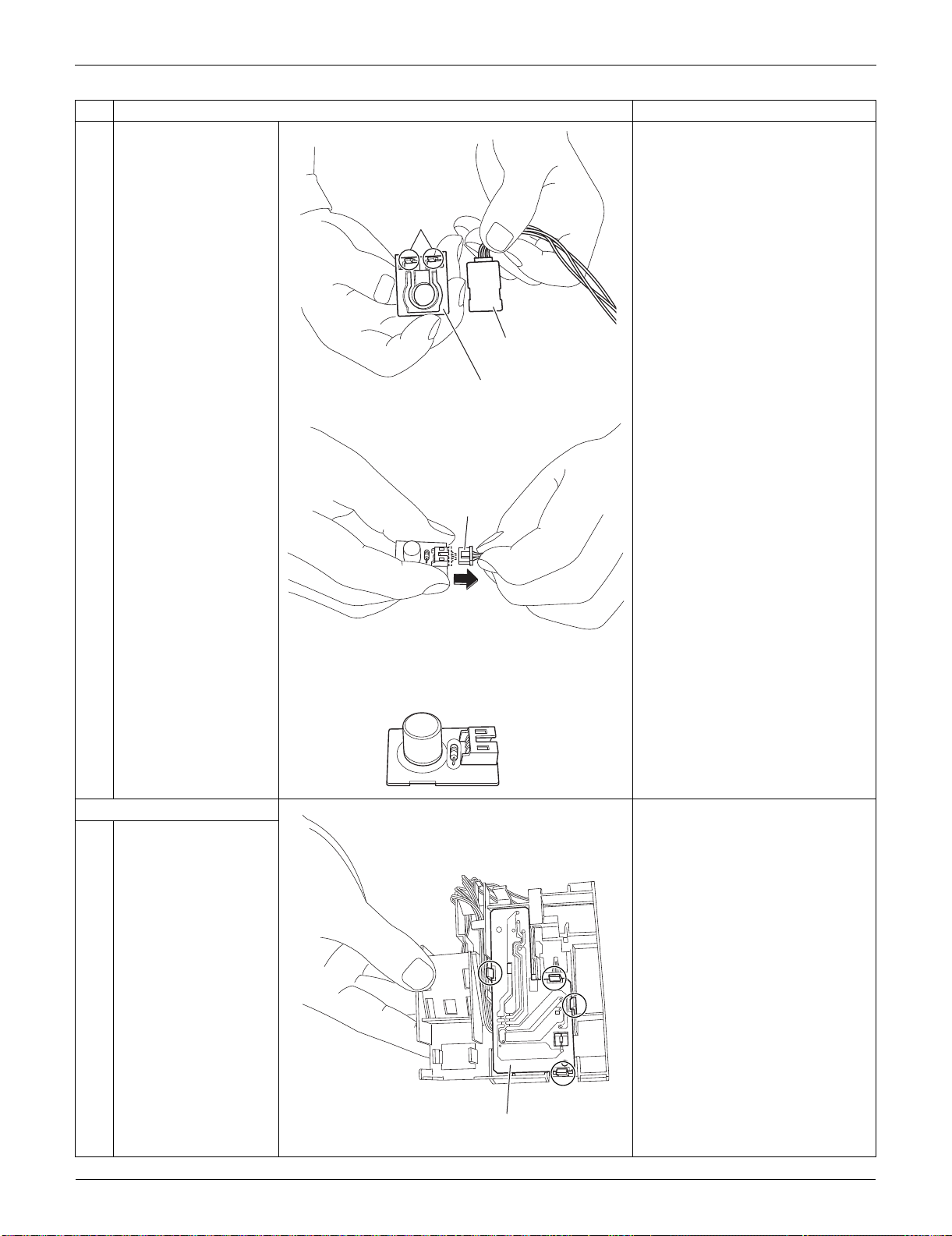
Indoor Unit: FTXS15/18/24LVJU SiUS091133
201 Removal Procedure
3
Remove the shield
plate by unfastening the
2 hooks.
4
Disconnect the
connector.
[S36]: control PCB
3. Remove the display PCB.
1
Unfasten the 4 hooks.
Step
Procedure Points
(R9526)
Shield plate (rear)
Hook
INTELLIGENT EYE
sensor PCB
(R9527)
[S36]
(R9528)
Display PCB
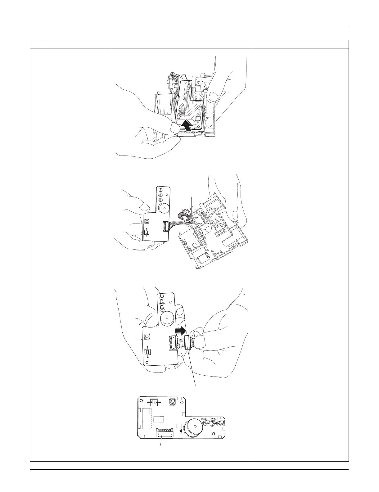
SiUS091133 Indoor Unit: FTXS15/18/24LVJU
Removal Procedure 202
2
Lift up the display PCB.
3
Release the harness
from the hook.
4
Disconnect the
connector.
[S49]: to control PCB
Step
Procedure Points
(R9529)
(R9530)
Hook
(R9531)
[S49]
3P224121-1
PbF
S49
SW1
BZ
LED1
LED2
LED3
(R13520)
[S49]
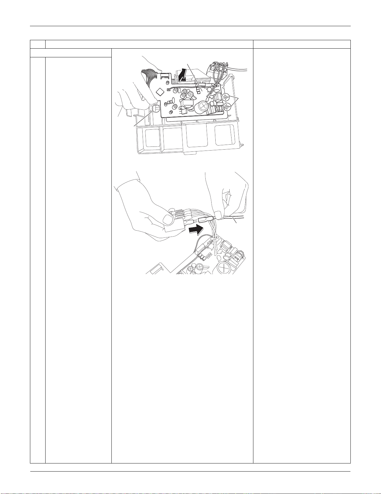
Indoor Unit: FTXS15/18/24LVJU SiUS091133
203 Removal Procedure
4. Remove the control PCB.
1
Unfasten the 3 hooks.
Lift up and remove the
control PCB.
2
Pull out the ground wire
from the terminal board.
Step
Procedure Points
(R9517)
Hook
Hook
Control PCB
(R16550)
Ground
wire
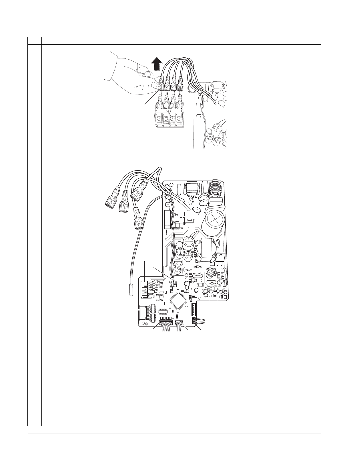
SiUS091133 Indoor Unit: FTXS15/18/24LVJU
Removal Procedure 204
3
Pull out the terminals
from the terminal board.
[S1] : DC fan motor
[S25] : INTELLIGENT EYE sensor
PCB
[S32] : indoor heat exchanger
thermistor
[S41] : swing motors
[S46] : display PCB
[S47] : signal receiver PCB
Refer to page 17 for detail.
Step
Procedure Points
(R9519)
Terminal
(R17042)
[S1]
[S32]
[S41]
[S46]
[S25]
[S47]
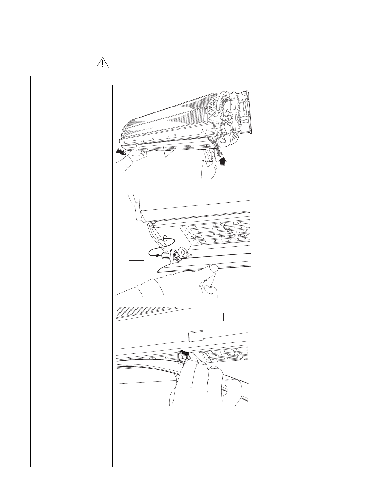
Indoor Unit: FTXS15/18/24LVJU SiUS091133
205 Removal Procedure
2.5 Removal of Horizontal Blades / Swing Motors
Procedure Warning Be sure to wait for 10 minutes or more after turning off all power supplies
before disassembling work.
Step
Procedure Points
1. Remove the horizontal
blades.
1
Hold the indoor unit up
with something sturdy
such as a piece of
wood.
2
Release the shafts in
turn.
(R9568)
Horizontal blade
(R9536)
left
(R9537)
inner right
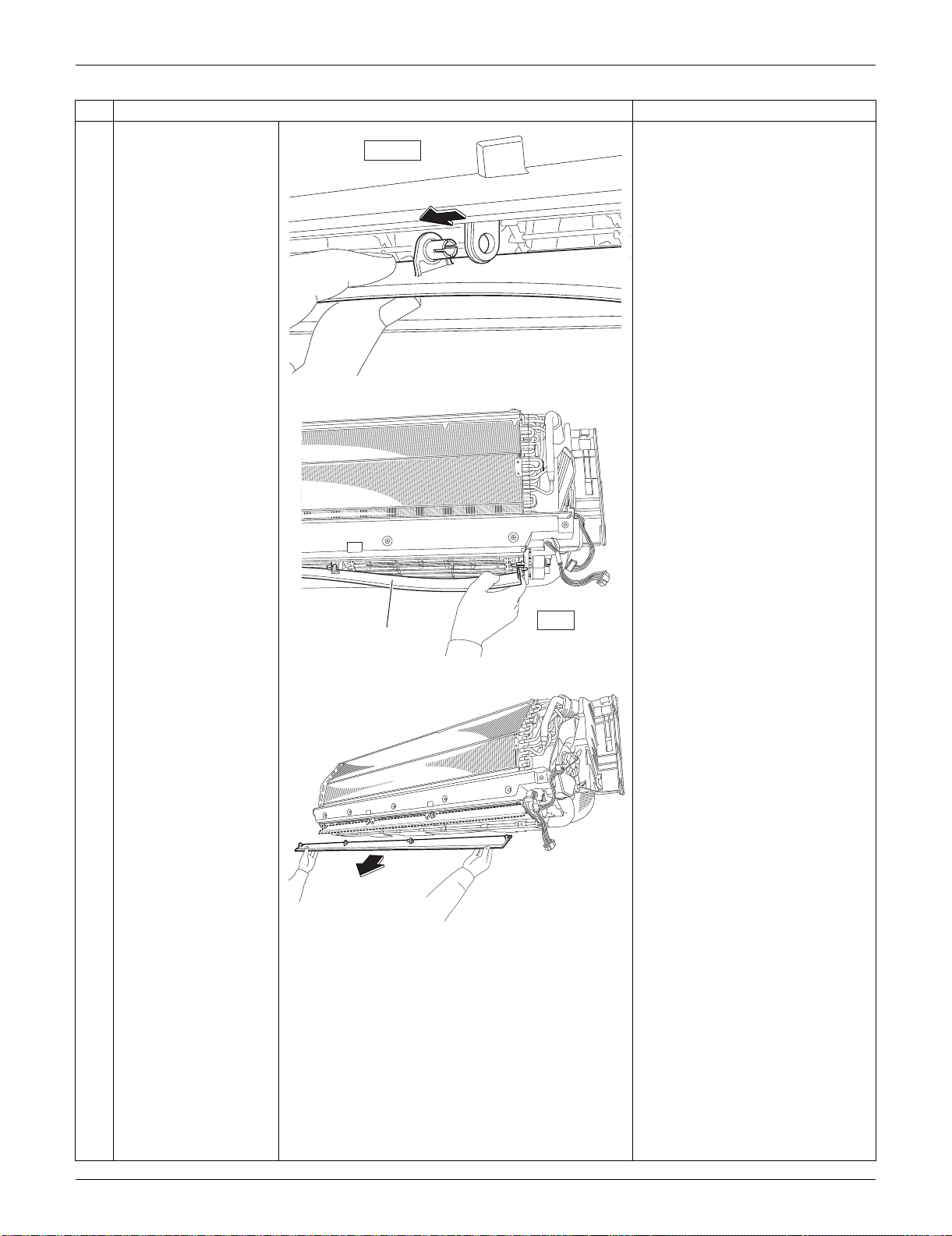
SiUS091133 Indoor Unit: FTXS15/18/24LVJU
Removal Procedure 206
3
Remove the horizontal
blade.
Remove both the horizontal
blades (upper and lower) in the
same way.
Step
Procedure Points
inner left
(R9538)
right
Horizontal
blade
(R9535)
(R16292)
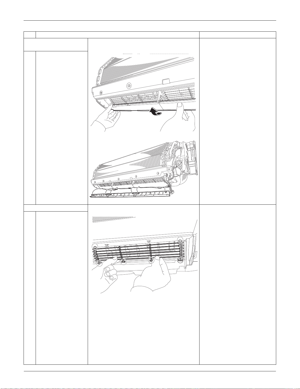
Indoor Unit: FTXS15/18/24LVJU SiUS091133
207 Removal Procedure
2. Remove the air outlet
ASSYs.
1
Remove the air outlet
ASSYs by pushing the
2 hooks at the back of
each.
The 3 air outlet ASSYs are
bound with sealing materials.
3. Remove the fan guards.
1
Unfasten the 4 lower
hooks and the 2 upper
hooks and remove the
fan guard.
Remove the other 2 fan guards
likewise.
Step
Procedure Points
(R16687)
(R16688)
(R16689)
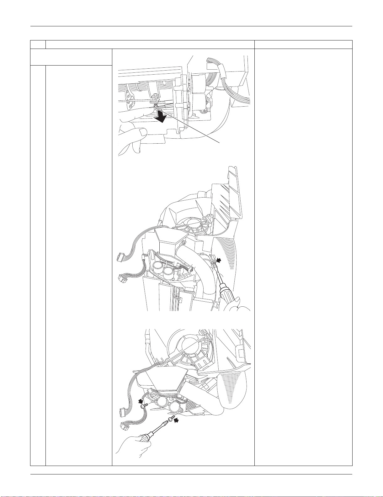
SiUS091133 Indoor Unit: FTXS15/18/24LVJU
Removal Procedure 208
4. Remove the swing motors
for horizontal blades.
1
Release the interlock
rod.
2
Remove the screw at
the rear of the indoor
unit.
3
Remove the 2 screws
(front and rear).
Step
Procedure Points
(R9546)
Interlock rod
(R16296)
(R16297)
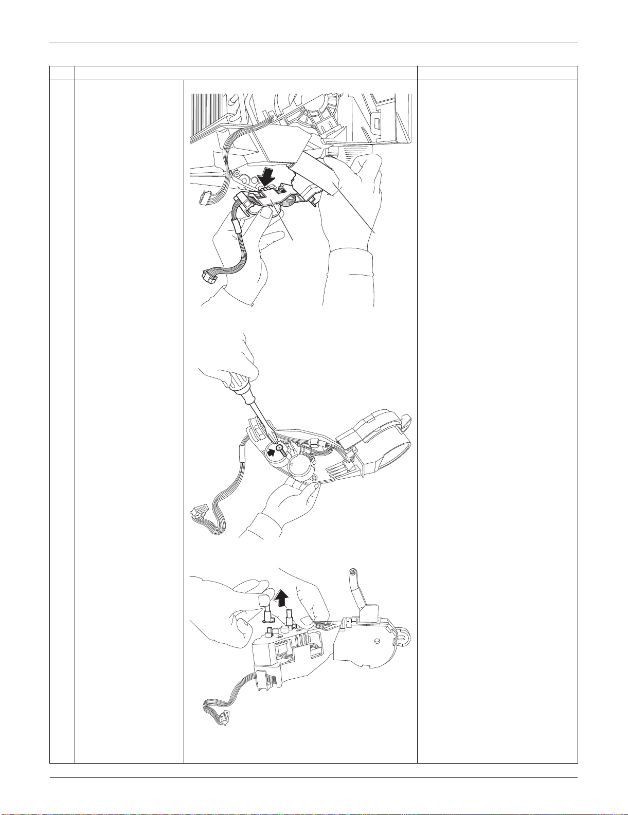
Indoor Unit: FTXS15/18/24LVJU SiUS091133
209 Removal Procedure
4
Pull out the drain hose,
then remove the swing
motor unit.
5
Remove the screw at
the center.
6
Remove the 2 pivots.
Step
Procedure Points
(R16298)
Drain hose
Swing motor
unit
(R9548)
(R9549)
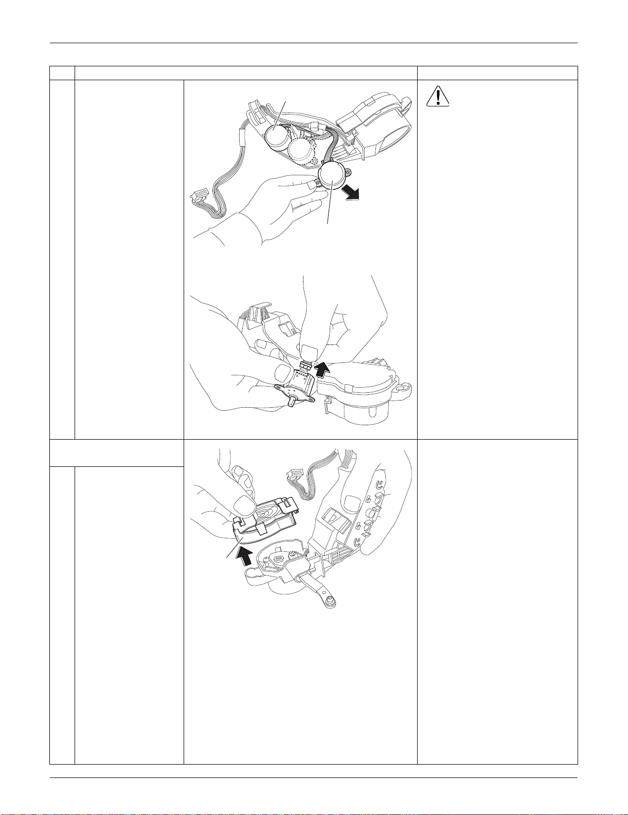
SiUS091133 Indoor Unit: FTXS15/18/24LVJU
Removal Procedure 210
7
Remove the swing
motors. Caution
When reassembling, do not
confuse the installing order of
the 2 motors and the colors of
the connectors.
If you set the connectors or
motors opposite, the horizontal
blades do not move smoothly or
noise may be heard.
(1) Set the swing motor of the upper
blade first.
(connector: white)
(2) Then, set the swing motor of the
lower blade.
(connector: red)
(3) Fix both swing motors with a
screw.
8
Disconnect the
connector to remove
the swing motor.
5. Remove the swing motor
for vertical blades.
1
Remove the link cover.
Step
Procedure Points
(R16079)
Swing motor (lower blade)
Swing motor (upper blade)
(R9551)
(R9552)
Link cover
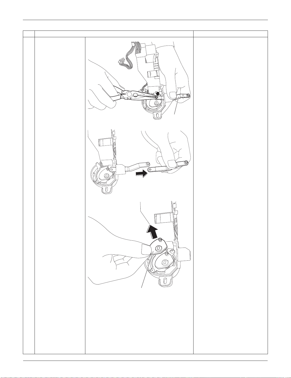
Indoor Unit: FTXS15/18/24LVJU SiUS091133
211 Removal Procedure
2
Remove the interlock
rod (2) with pliers.
3
Remove the interlock
rod (1).
Step
Procedure Points
(R9553)
Interlock rod (2)
(R9554)
(R9555)
Interlock rod (1)
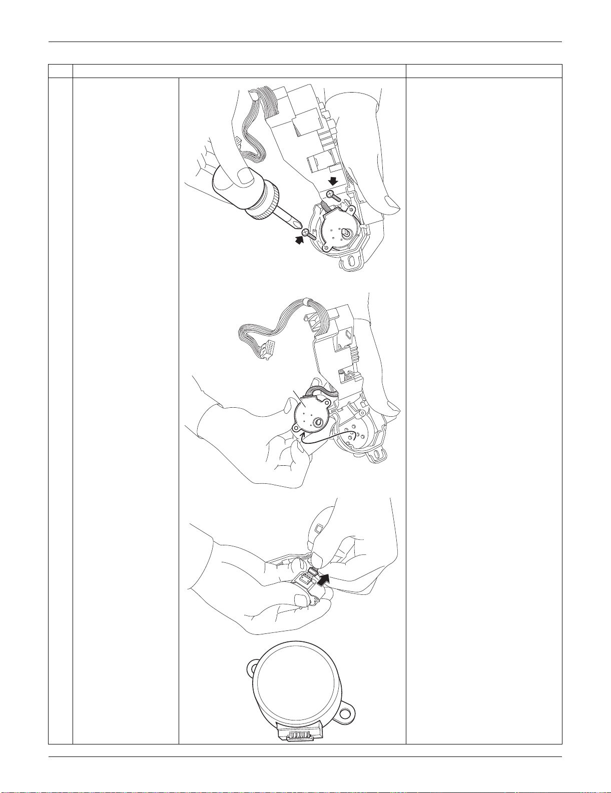
SiUS091133 Indoor Unit: FTXS15/18/24LVJU
Removal Procedure 212
4
Remove the 2 screws.
5
Remove the swing
motor for the vertical
blade.
6
Disconnect the
connector.
Step
Procedure Points
(R9556)
(R9557)
Swing motor for
vertical blade
(R9558)
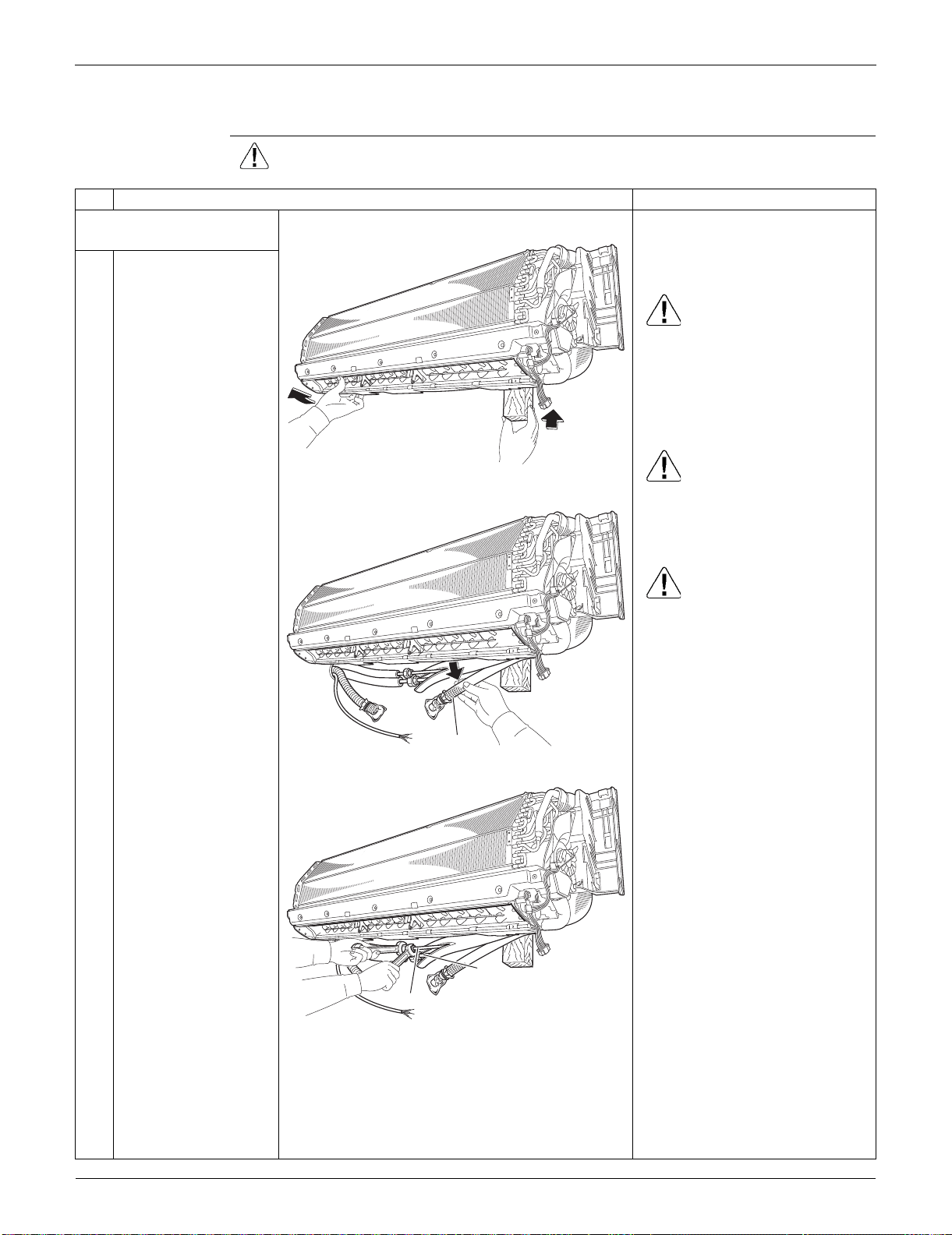
Indoor Unit: FTXS15/18/24LVJU SiUS091133
213 Removal Procedure
2.6 Removal of Indoor Heat Exchanger
Procedure Warning Be sure to wait for 10 minutes or more after turning off all power supplies
before disassembling work.
Step
Procedure Points
1. Disconnect the refrigerant
piping.
Preparation
Remove the electrical box
according to the “Removal of
Electrical Box”.
Caution
If the refrigerant leaks, repair the
leakage, then collect all
refrigerant from the unit. After
conducting vacuum drying,
recharge a proper amount of
refrigerant.
Caution
From the viewpoint of global
environment protection, be sure
to use a vacuum pump for air
purging.
Caution
In pump-down work, be sure to
stop the compressor before
disconnecting the refrigerant
piping. If the refrigerant piping is
disconnected with the
compressor operating and the
stop valve open, air may be
sucked in to generate an over-
pressure in refrigeration cycle,
thus resulting in pipe rupture or
accidental injury.
Place a plastic sheet under the
drain pan to prevent from
wetting the floor with remaining
drain.
If the drain hose is embedded in
the wall, disconnect the drain
hose beforehand.
Carry out the removal work with
2 wrenches.
When the pipings are
disconnected, protect both the
openings of pipe and unit from
entering moisture.
1
Hold the indoor unit up
with a piece of wood
etc.
2
Pull out the drain hose.
3
Unscrew the flare nuts
for gas piping and liquid
piping.
(R16521)
(R16522)
Drain hose
(R16523)
Liquid piping
Gas piping
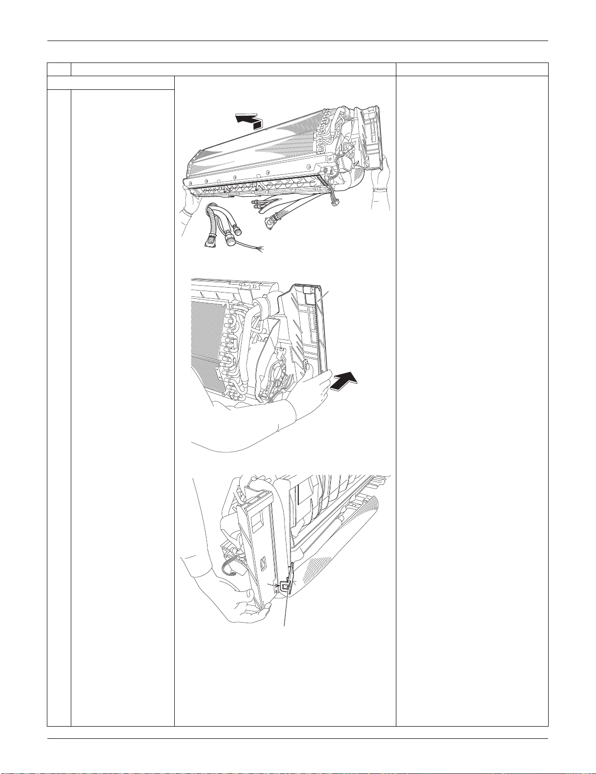
SiUS091133 Indoor Unit: FTXS15/18/24LVJU
Removal Procedure 214
2. Remove the piping fixture.
1
Detach the indoor unit
from the installation
plate.
2
Push the bottom frame.
3
Release the piping
fixture.
Step
Procedure Points
(R16524)
(R16309)
Bottom frame
(R9573)
Piping fixture
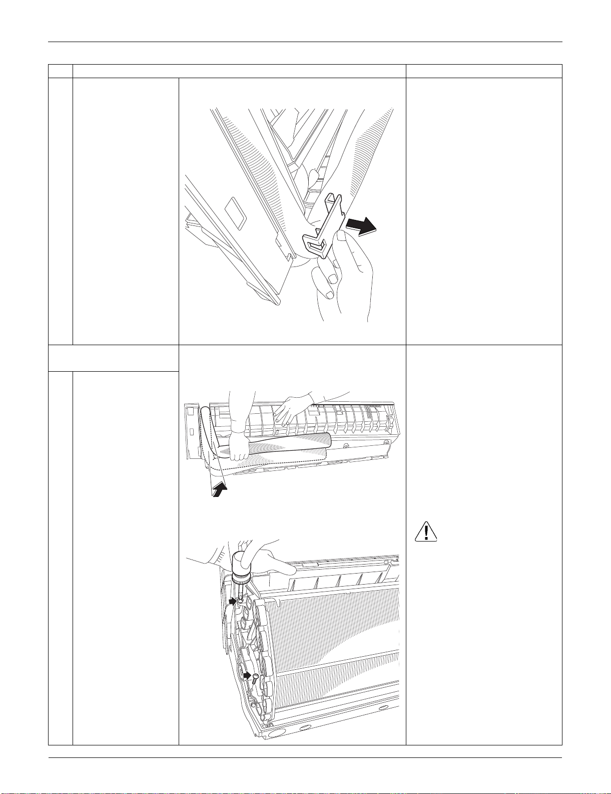
Indoor Unit: FTXS15/18/24LVJU SiUS091133
215 Removal Procedure
4
Remove the piping
fixture.
3. Remove the indoor heat
exchanger.
1
Widen the auxiliary
piping.
2
Remove the 2 screws
on the left side. Caution
When removing or reassembling
the indoor heat exchanger, be
sure to wear gloves or wrap the
indoor heat exchanger with
cloths. (You may be injured by
the fins.)
Step
Procedure Points
(R9574)
(R9575)
(R13580)
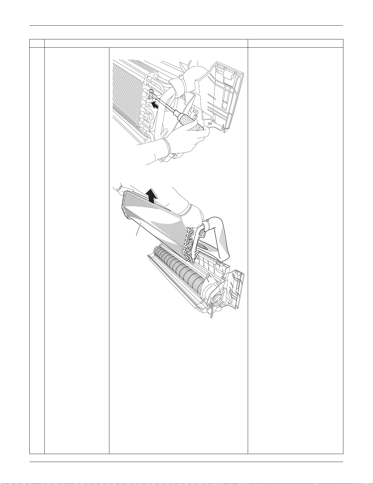
SiUS091133 Indoor Unit: FTXS15/18/24LVJU
Removal Procedure 216
3
Push the hook on the
right side and unfasten
it.
4
Lift up and remove the
indoor heat exchanger.
Press the right side of the indoor
heat exchanger, and lift it up
from the left side.
Step
Procedure Points
(R16310)
(R16311)
Indoor heat
exchanger
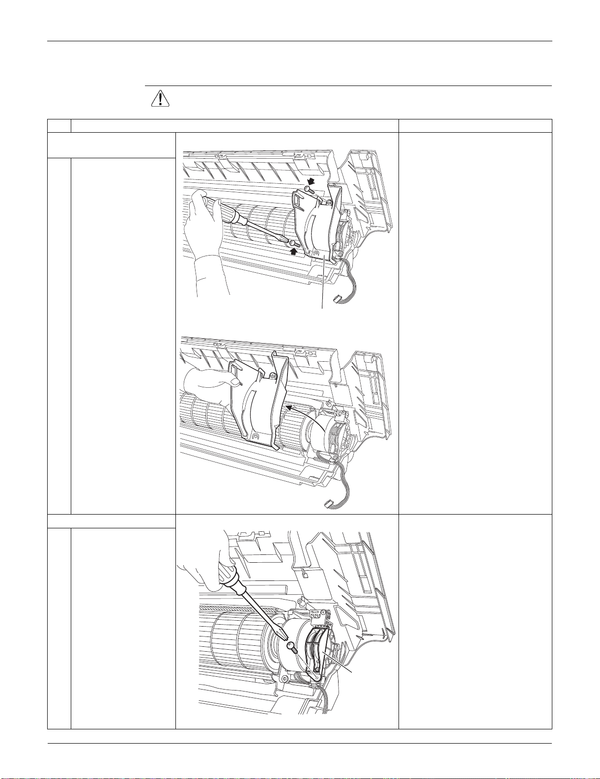
Indoor Unit: FTXS15/18/24LVJU SiUS091133
217 Removal Procedure
2.7 Removal of Fan Motor / Fan Rotor
Procedure Warning Be sure to wait for 10 minutes or more after turning off all power supplies
before disassembling work.
Step
Procedure Points
1. Remove the right side
plate.
1
Remove the 2 screws.
2
Lift the right side plate
and remove it.
2. Remove the fan rotor.
1
Remove the screw of
the fan motor fixing
plate.
(R16306)
Right side plate
(R16307)
(R16972)
Fan motor
fixing plate
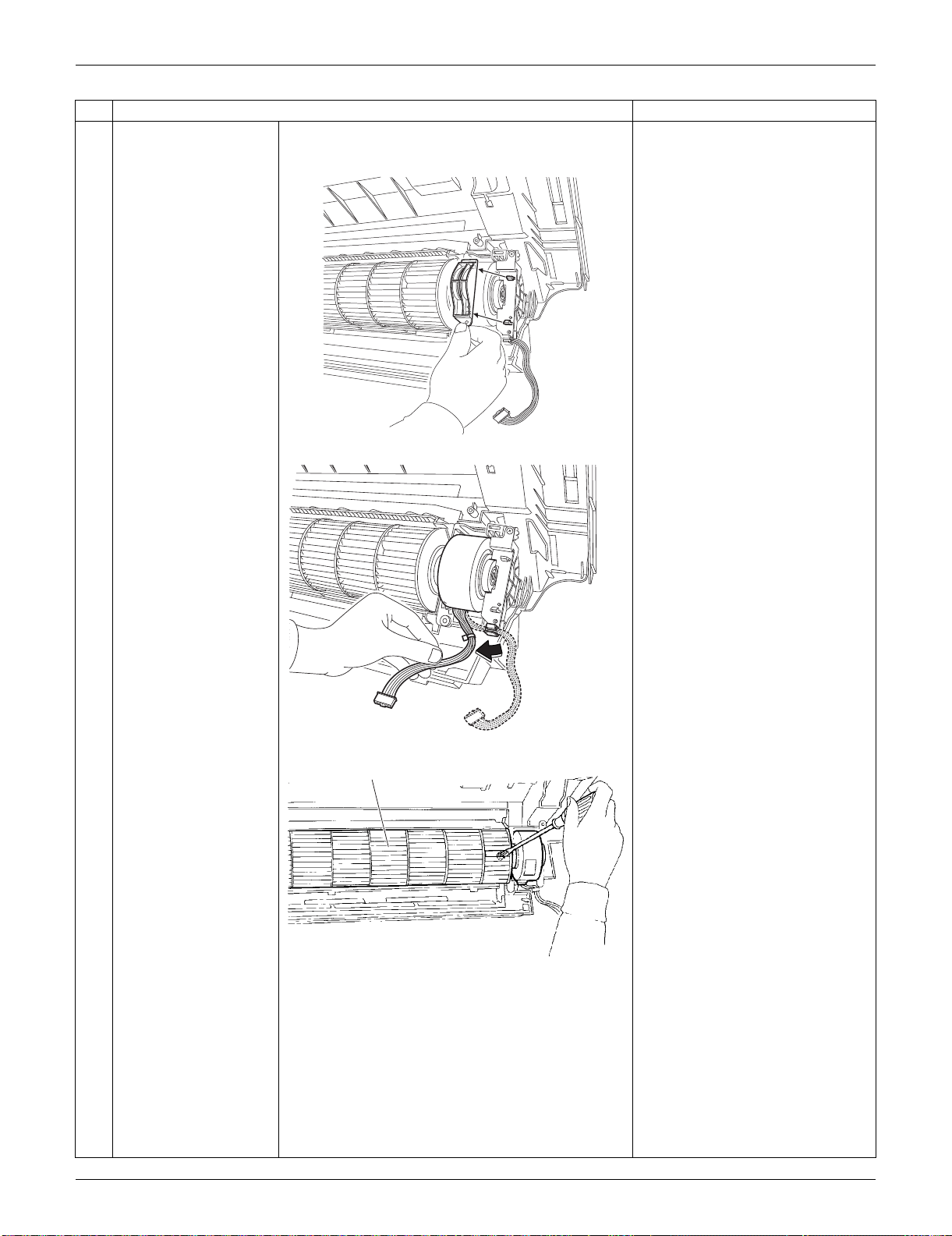
SiUS091133 Indoor Unit: FTXS15/18/24LVJU
Removal Procedure 218
2
Remove the fan motor
fixing plate.
3
Release the fan motor
harness from the hook.
4
Loosen the screw of the
fan rotor.
Step
Procedure Points
(R16973)
(R16304)
Fan rotor
(R9648)
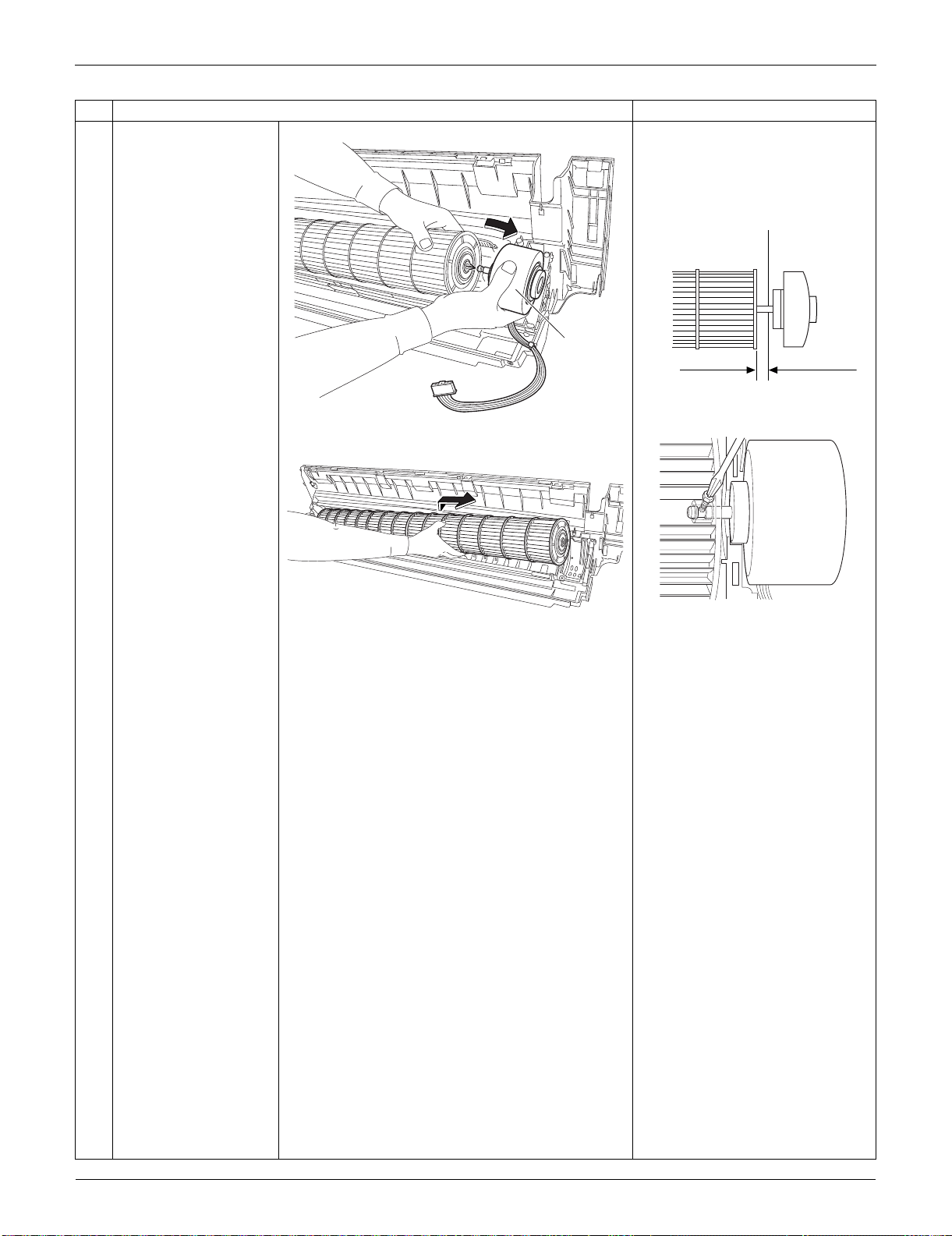
Indoor Unit: FTXS15/18/24LVJU SiUS091133
219 Removal Procedure
5
Remove the fan motor. When reassembling the fan
motor and the fan rotor, provide
as much as 5 mm (0.2 inch) of
play between the side face of
the rotor and the bottom frame.
(1) Insert the fan motor with approx.
5 mm (0.2 inch) left.
(2) Tighten the screw until it stops.
Then give the screw one more
turn.
(3) Rotate the fan rotor and confirm
the fan motor and the fan rotor
are installed appropriately.
(4) Tighten the screw completely if
appropriate.
(5) If not appropriate, go back to
(1).
6
Remove the fan rotor.
Step
Procedure Points
(R16305)
Fan motor
5 mm (0.2 inch)
Side face of rotor
(R2808)
Side face of
bottom frame
(R9582)
(R9584)
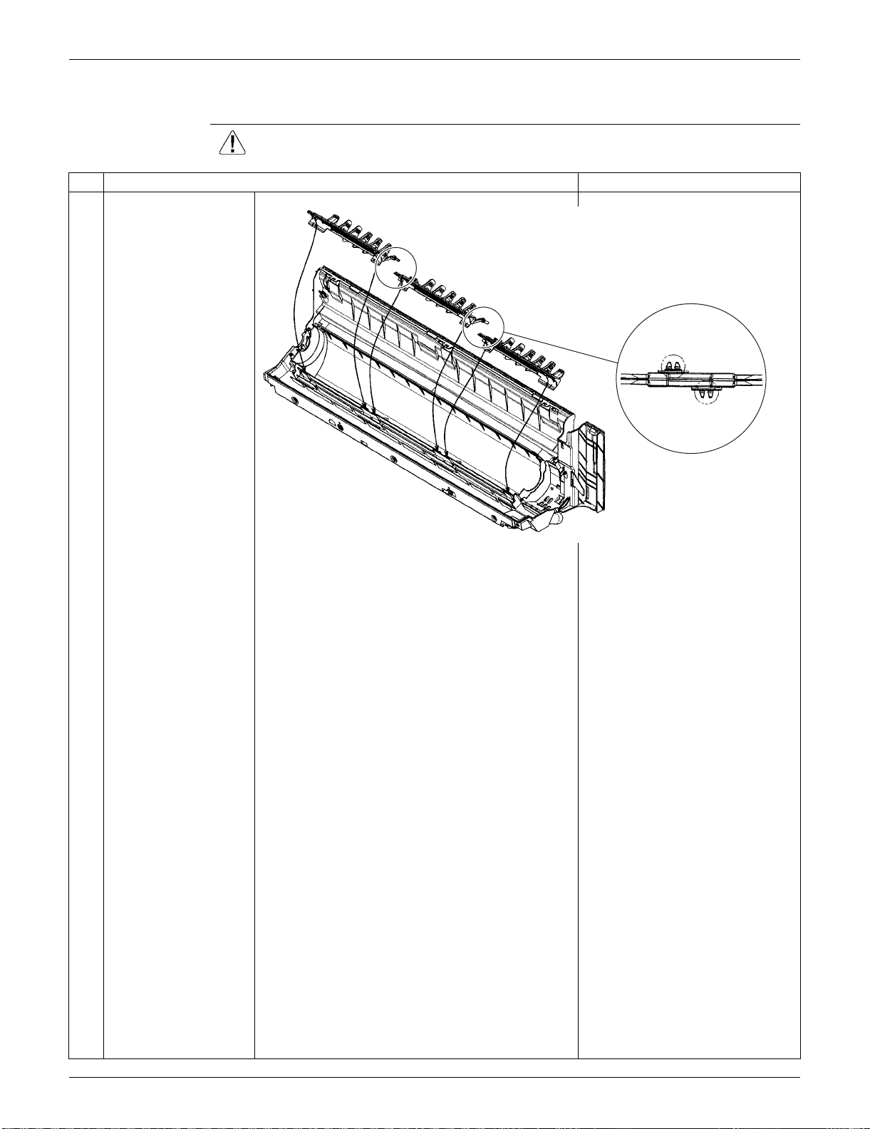
SiUS091133 Indoor Unit: FTXS15/18/24LVJU
Removal Procedure 220
2.8 Removal of Vertical Blade ASSYs
Procedure Warning Be sure to wait for 10 minutes or more after turning off all power supplies
before disassembling work.
Step
Procedure Points
Unfasten the 2 hooks of
each vertical blade
ASSY.
Remove the 3 vertical
blade ASSYs.
Each vertical blade ASSY is
united with a drain pan ASSY.
(R16504)
When reassembling,
connect the 3 vertical blade
ASSYs. Fasten the hooks at
the connecting points.
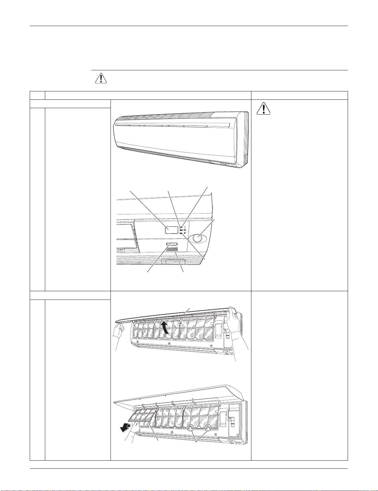
Indoor Unit: FTXS30/36LVJU SiUS091133
221 Removal Procedure
3. Indoor Unit: FTXS30/36LVJU
3.1 Removal of Air Filters / Front Panel
Procedure Warning Be sure to wait for 10 minutes or more after turning off all power supplies
before disassembling work.
Step
Procedure Points
1. Appearance features
Warning
Dangerous: High voltage
A high voltage is applied to all
the electric circuits of this
product including thermistors.
When the signal receiver
catches a signal from the
remote controller, the receiving
tone sounds and the operation
lamp blinks immediately to
confirm the signal reception.
When the [ON/OFF] button is
kept pressed for 5 seconds, the
forced cooling operation is
performed for about 15 minutes.
2. Remove the air filters.
1
Open the front panel to
the position where it
stops.
2
Slightly push up the
center knob of the air
filter and unfasten the
hooks.
The 3 filters are
interchangeable.
The air filter can be set easily by
inserting it along the guides.
Insert the air filter with the
"FRONT" mark faced up.
Be sure to insert the hooks (at 2
lower positions) when
reassembling the air filter.
3
Pull out the air filter
downward and remove
it.
(R9473)
ON/OFF
(R16974)
Operation lamp
TIMER lampSignal receiver
Room temperature thermistorON/OFF button
INTELLIGENT
EYE sensor
INTELLIGENT
EYE lamp
(R9475)
Front Panel
(R13625)
Air filter
Hook
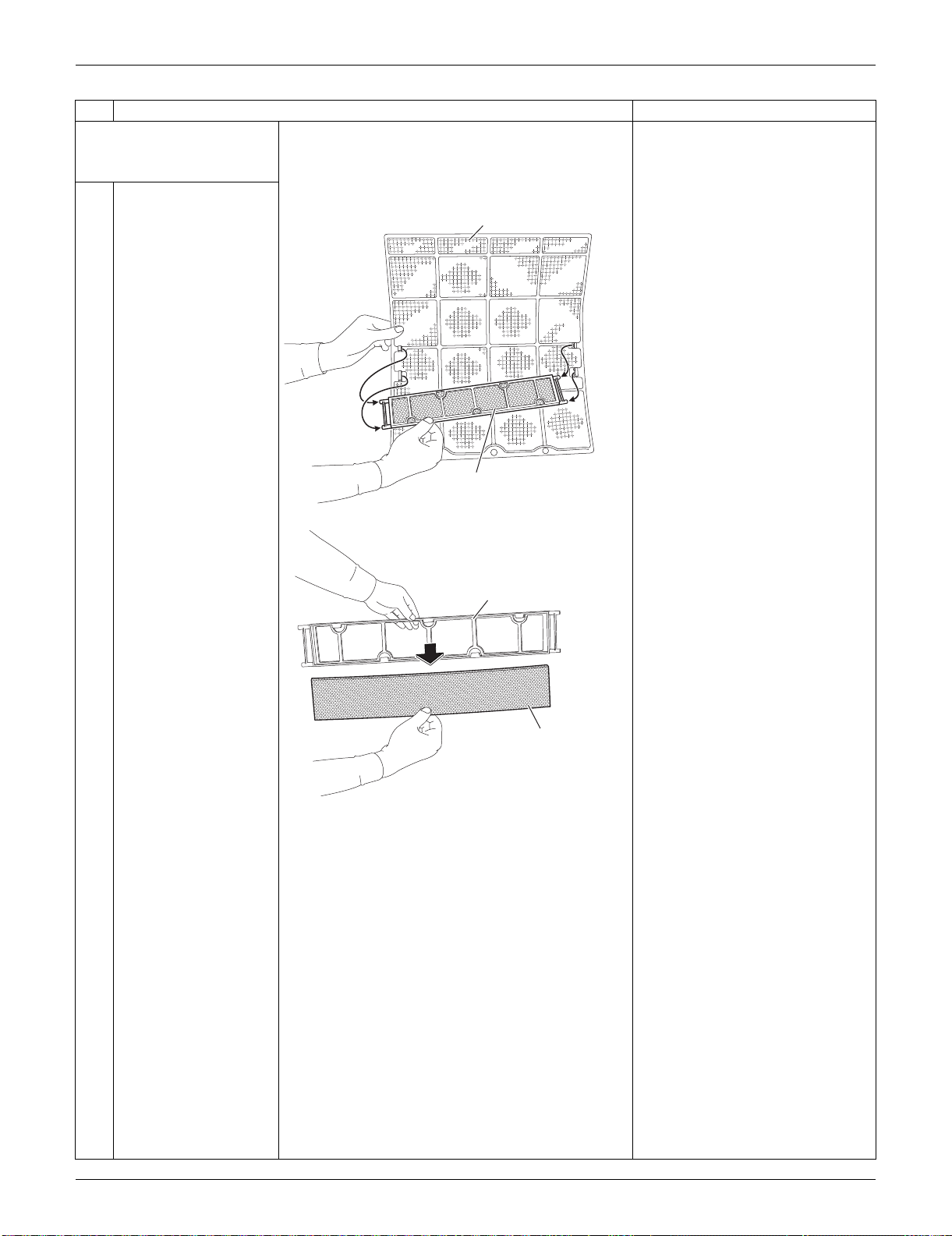
SiUS091133 Indoor Unit: FTXS30/36LVJU
Removal Procedure 222
3. Remove the Titanium
apatite photocatalytic air-
purifying filters.
1
Remove the Titanium
apatite photocatalytic
air-purifying filter ASSY
by unfastening the
projections from the
back of the air filter
frame.
The 3 filters are
interchangeable.
2
Remove the Titanium
apatite photocatalytic
air-purifying filter from
its frame.
Step
Procedure Points
(R9477)
Air filter
Titanium apatite photocatalytic
air-purifying filter ASSY
(R9478)
Frame
Titanium apatite photocatalytic
air-purifying filter
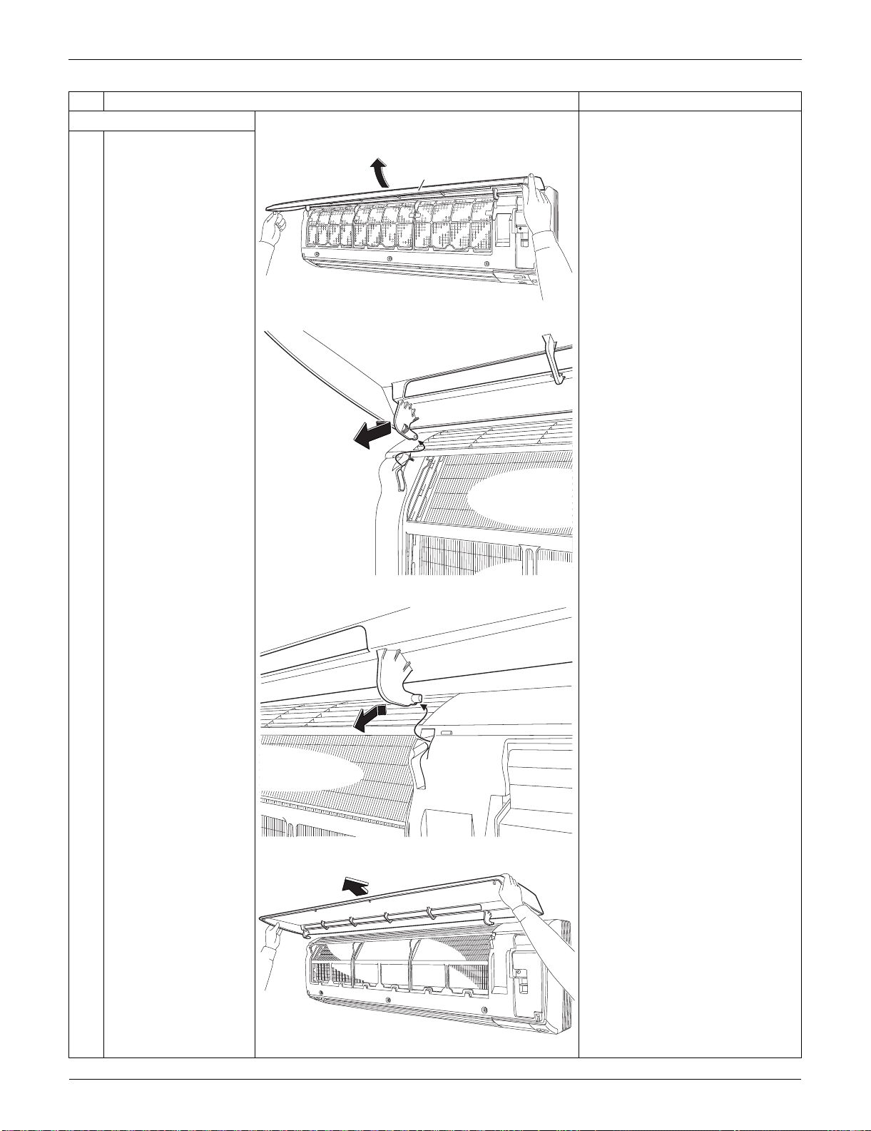
Indoor Unit: FTXS30/36LVJU SiUS091133
223 Removal Procedure
4. Remove the front panel.
1
While opening the front
panel further than it
stops, release both the
shafts.
Slide the front panel from side to
side to release each shaft.
Align the right and left shafts
with grooves in turn and insert
them to the end when
reassembling.
2
Remove the front
panel.
Step
Procedure Points
(R9479)
Front Panel
(R9480)
(R9481)
(R9482)
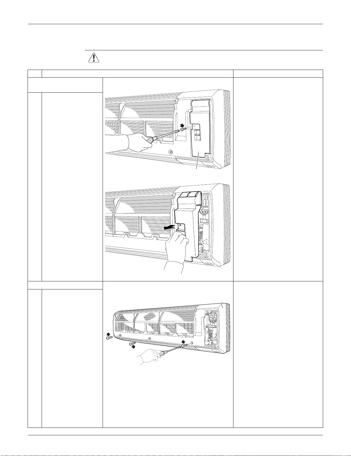
SiUS091133 Indoor Unit: FTXS30/36LVJU
Removal Procedure 224
3.2 Removal of Front Grille
Procedure Warning Be sure to wait for 10 minutes or more after turning off all power supplies
before disassembling work.
Step
Procedure Points
1. Remove the service
cover.
1
Remove the screw and
remove the service
cover.
You can remove the front grille
without detaching the service
cover.
2. Remove the front grille.
1
Remove the 3 screws
of the front grille.
Refer to the removal procedure
in a reverse way when
reassembling.
(R9483)
Service cover
(R9484)
(R9485)
Front grille
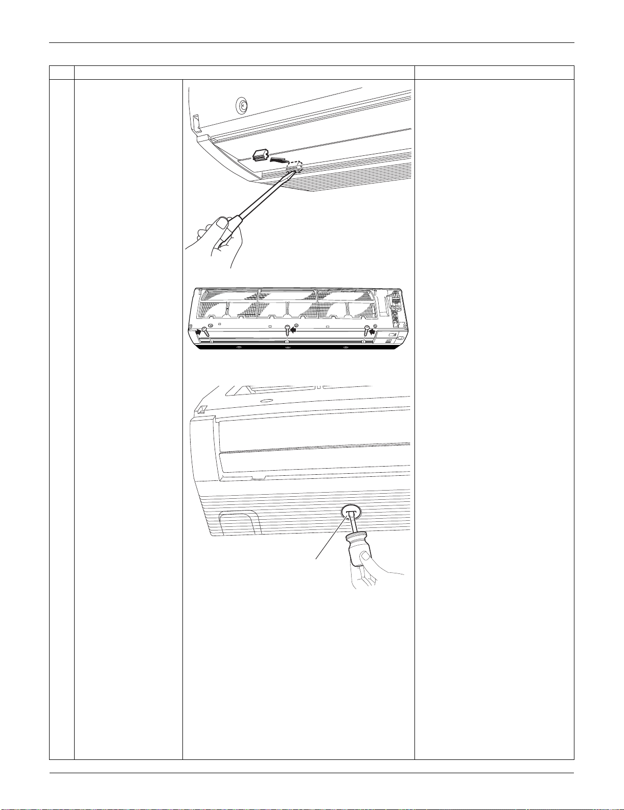
Indoor Unit: FTXS30/36LVJU SiUS091133
225 Removal Procedure
2
Remove the screw
caps with a flat
screwdriver.
3
Remove the lower 3
screws.
4
Remove the 3 front
grille fixtures.
The Illustration shows the left
fixture.
Step
Procedure Points
(R16266)
(R9488)
(R9489)
Front grille fixture
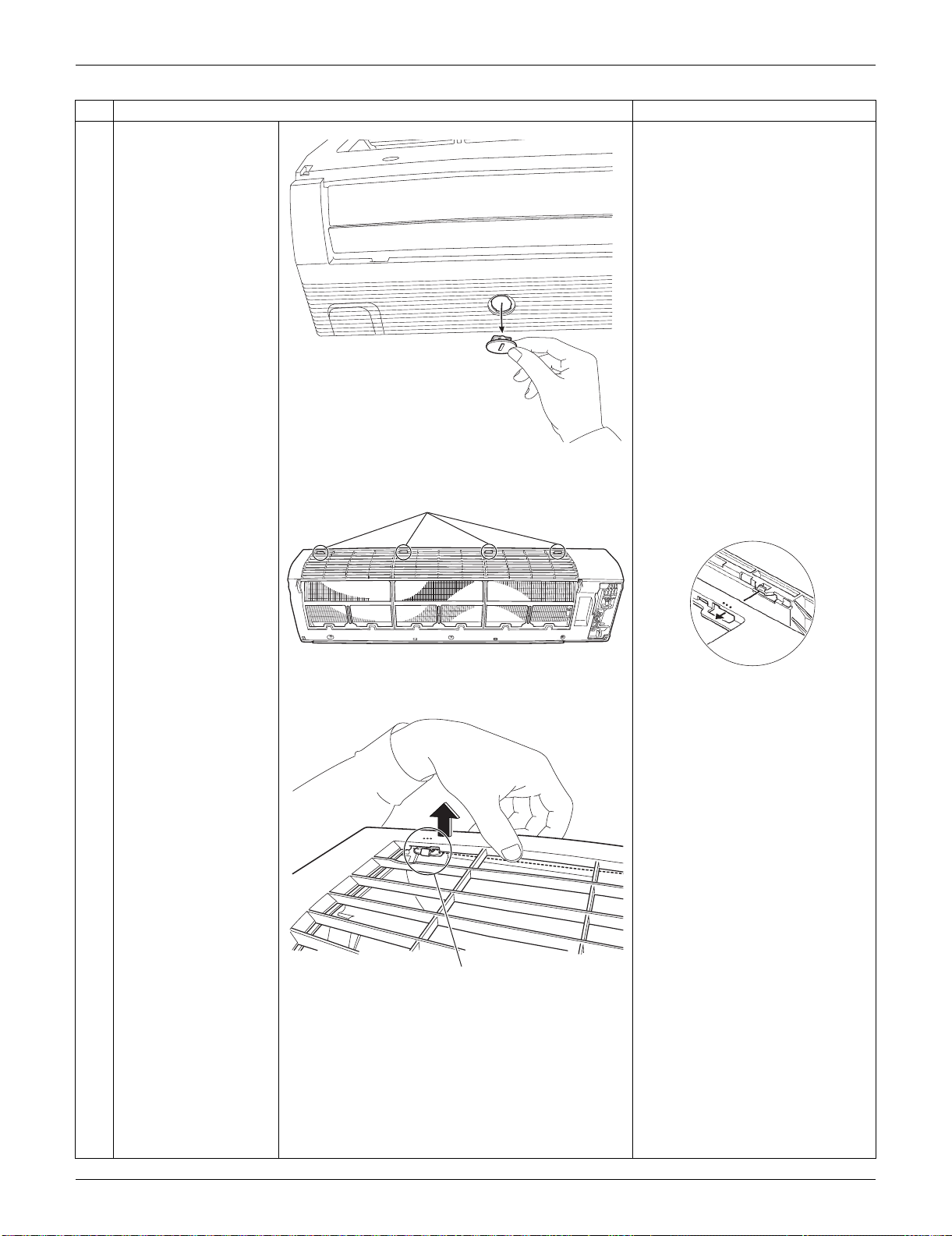
SiUS091133 Indoor Unit: FTXS30/36LVJU
Removal Procedure 226
5
Unfasten the 4 hooks
on the top of the front
grille.
The convex marks (...) on the
front panel indicate the position
of the hooks.
Step
Procedure Points
(R9490)
(R9486)
Hook
(R12715)
(R9487)
Hook

Indoor Unit: FTXS30/36LVJU SiUS091133
227 Removal Procedure
6
Pull the upper part of
the front grille out and
lift the lower part up,
and then remove the
front grille.
When reassembling, make sure
that all the 4 hooks are fastened
as they were.
Step
Procedure Points
(R9492)
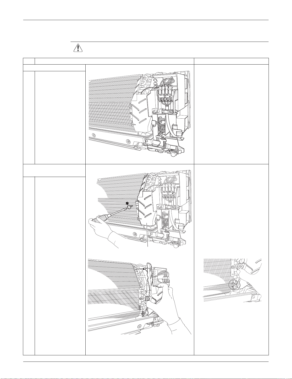
SiUS091133 Indoor Unit: FTXS30/36LVJU
Removal Procedure 228
3.3 Removal of Electrical Box
Procedure Warning Be sure to wait for 10 minutes or more after turning off all power supplies
before disassembling work.
Step
Procedure Points
1. Layout of the parts
Preparation
Remove the front grille
according to the “Removal of
Front Grille.”
2. Remove the drip proof
plate.
1
Remove the screw.
2
Remove the drip proof
plate from the indoor
heat exchanger.
When reassembling, fit the hook
to the indoor heat exchanger.
1
2
3
(R9493)
1
2
3
(R9494)
Drip proof plate
(R9496)
(R9495)
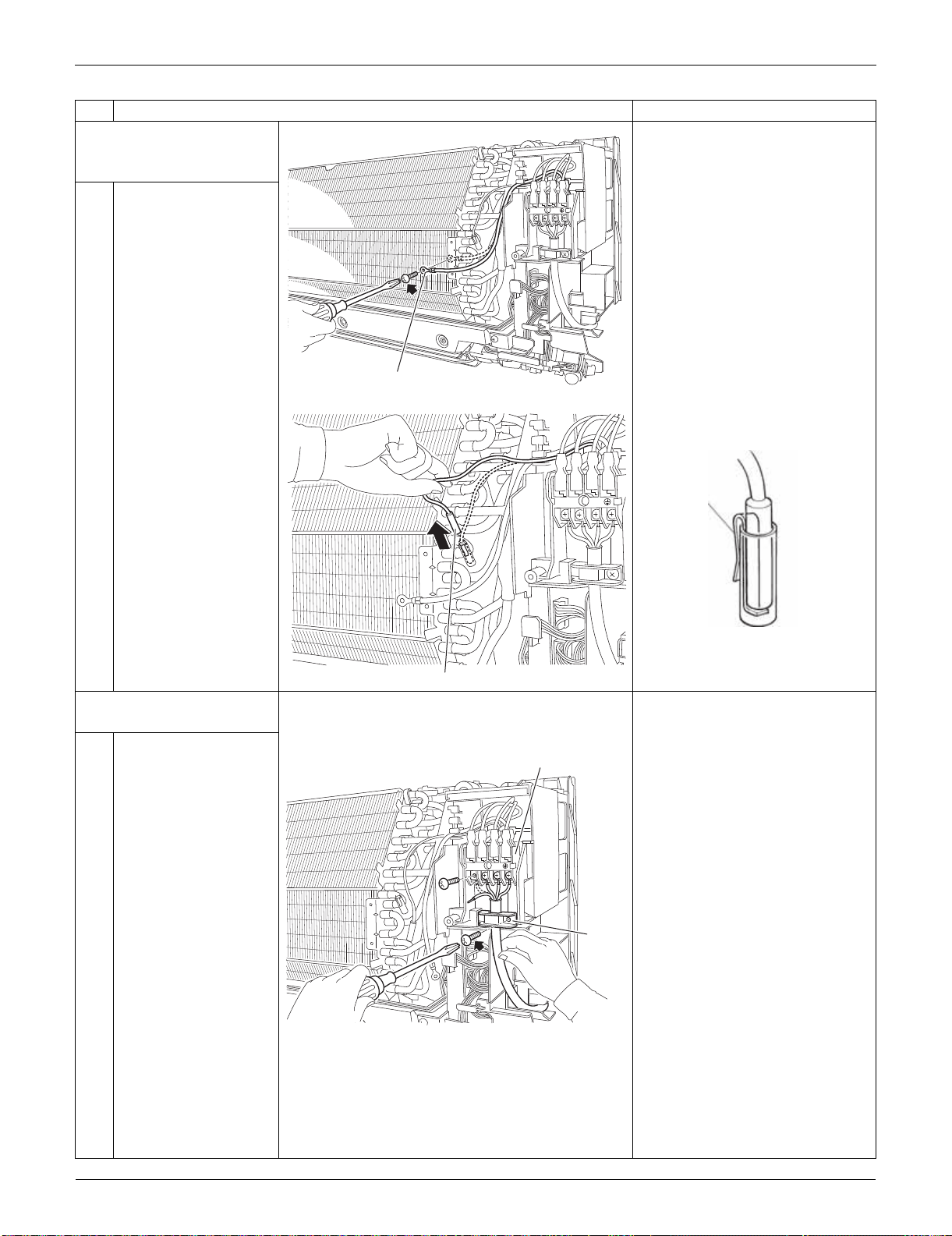
Indoor Unit: FTXS30/36LVJU SiUS091133
229 Removal Procedure
3. Release the ground wire
and the indoor heat
exchanger thermistor.
1
Remove the screw and
release the ground
wire.
2
Pull out the indoor heat
exchanger thermistor.
Be careful not to lose the clip of
the thermistor.
4. Remove the electrical
box.
1
Remove the 4 screws
and disconnect the
connection wires on the
terminal board.
Remove the screw and
remove the wire
retainer.
Step
Procedure Points
1
2
3
(R16976)
Ground wire
1
2
3
(R9498)
Indoor heat exchanger thermistor
Clip
(R11268)
1
2
3
(R9499)
Terminal board
Wire
retainer
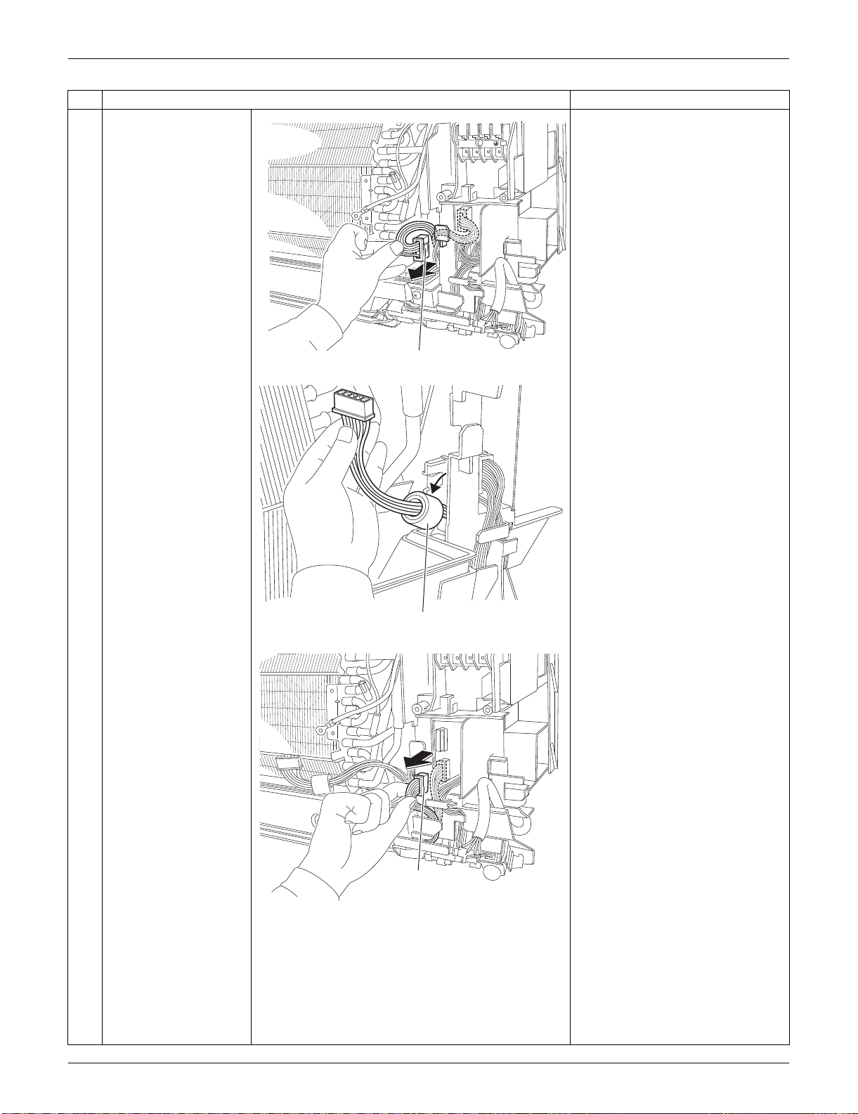
SiUS091133 Indoor Unit: FTXS30/36LVJU
Removal Procedure 230
2
Disconnect the
connector for the fan
motor [S1] and release
the harness from the
hook.
3
Release the ferrite
core.
4
Disconnect the
connector for the swing
motors [S41].
Step
Procedure Points
1
2
3
(R9500)
[S1]
(R9501)
Ferrite core
(R9502)
[S41]
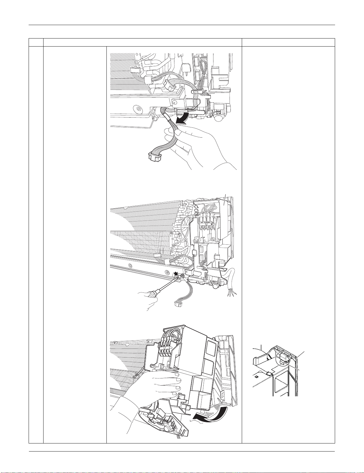
Indoor Unit: FTXS30/36LVJU SiUS091133
231 Removal Procedure
5
Release the harness
from the hooks.
6
Remove the screw of
the electrical box.
7
Lift up the electrical box
from the bottom frame
and remove it.
Fit the back hook of the
electrical box to the bottom
frame when reassembling.
Step
Procedure Points
(R9503)
1
2
3
(R9504)
Electrical box
(R9505)
(R9647)
Bottom frame
Hook
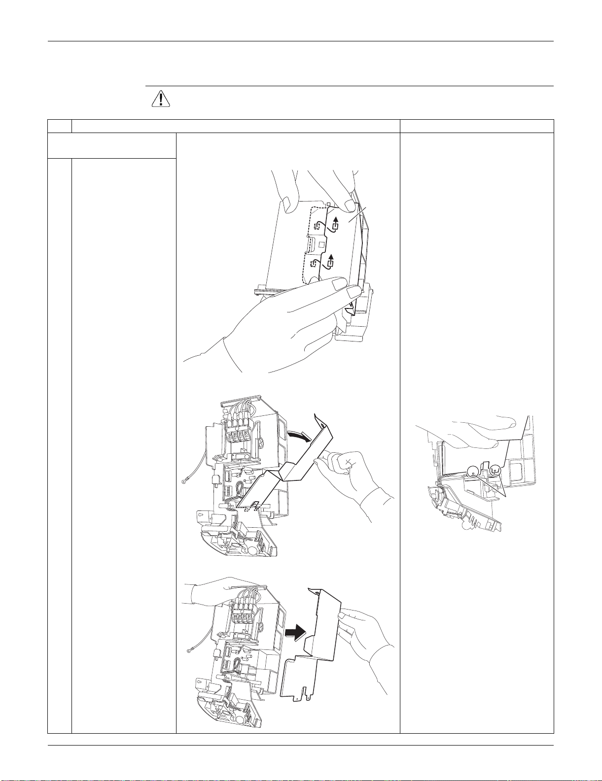
SiUS091133 Indoor Unit: FTXS30/36LVJU
Removal Procedure 232
3.4 Removal of PCBs
Procedure Warning Be sure to wait for 10 minutes or more after turning off all power supplies
before disassembling work.
Step
Procedure Points
1. Remove the signal
receiver PCB.
1
Unfasten the hooks of
the shield plate.
2
Open the shield plate. The shield plate has 2 hooks at
the lower part also.
3
Remove the shield
plate.
(R9506)
Shield
plate
(R9507)
(R9508)
Hook
(R9509)
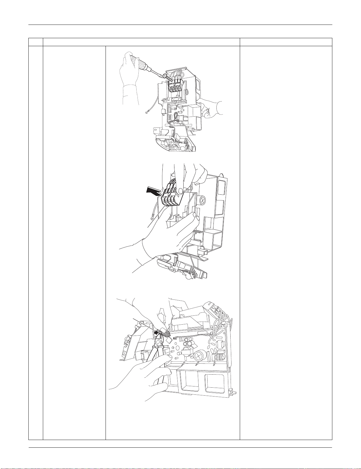
Indoor Unit: FTXS30/36LVJU SiUS091133
233 Removal Procedure
4
Remove the screw of
the terminal board.
5
Remove the terminal
board.
(1 hook at the back)
6
Cut the clamp.
Step
Procedure Points
(R9511)
(R9512)
Terminal board
(R9513)
Clamp
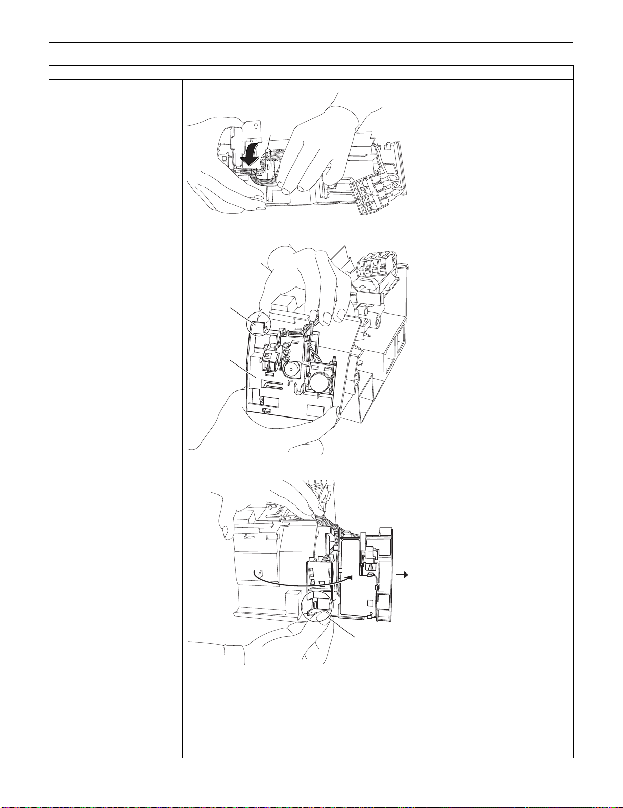
SiUS091133 Indoor Unit: FTXS30/36LVJU
Removal Procedure 234
7
Release the harness
from the hook.
When reassembling, make sure
to hook the harness.
8
Push and unfasten the
hook of the signal
receiver unit.
9
Open the signal
receiver unit.
Unfasten the hook and
remove the signal
receiver unit.
Step
Procedure Points
(R9514)
Hook
(R13518)
Hook
Signal
receiver
unit
(R9516)
Hook
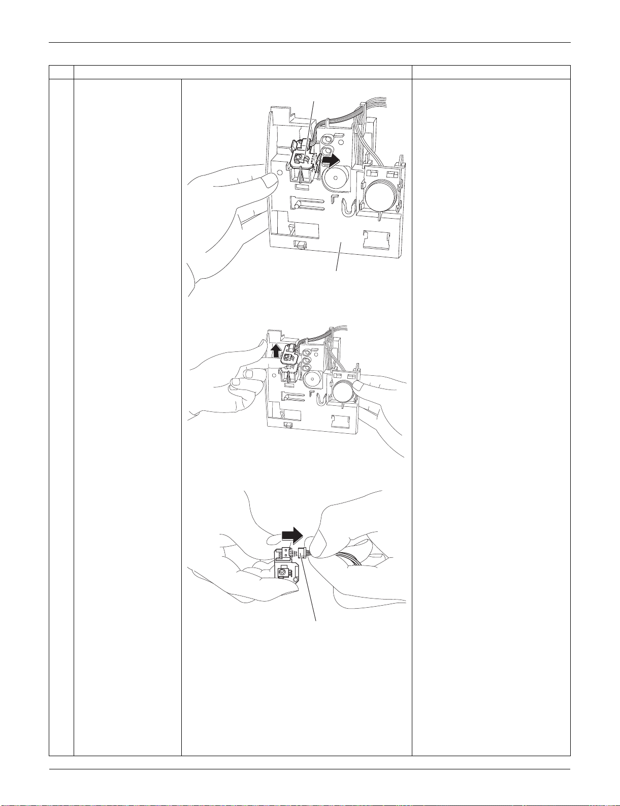
Indoor Unit: FTXS30/36LVJU SiUS091133
235 Removal Procedure
10
Unfasten the hook on
the right of the signal
receiver PCB.
(Then the signal
receiver PCB is lifted
up.)
11
Remove the signal
receiver PCB.
12
Disconnect the
connector.
[S48]: control PCB
Step
Procedure Points
(R13519)
Signal receiver PCB
Signal receiver unit
(R9521)
(R9522)
[S48]
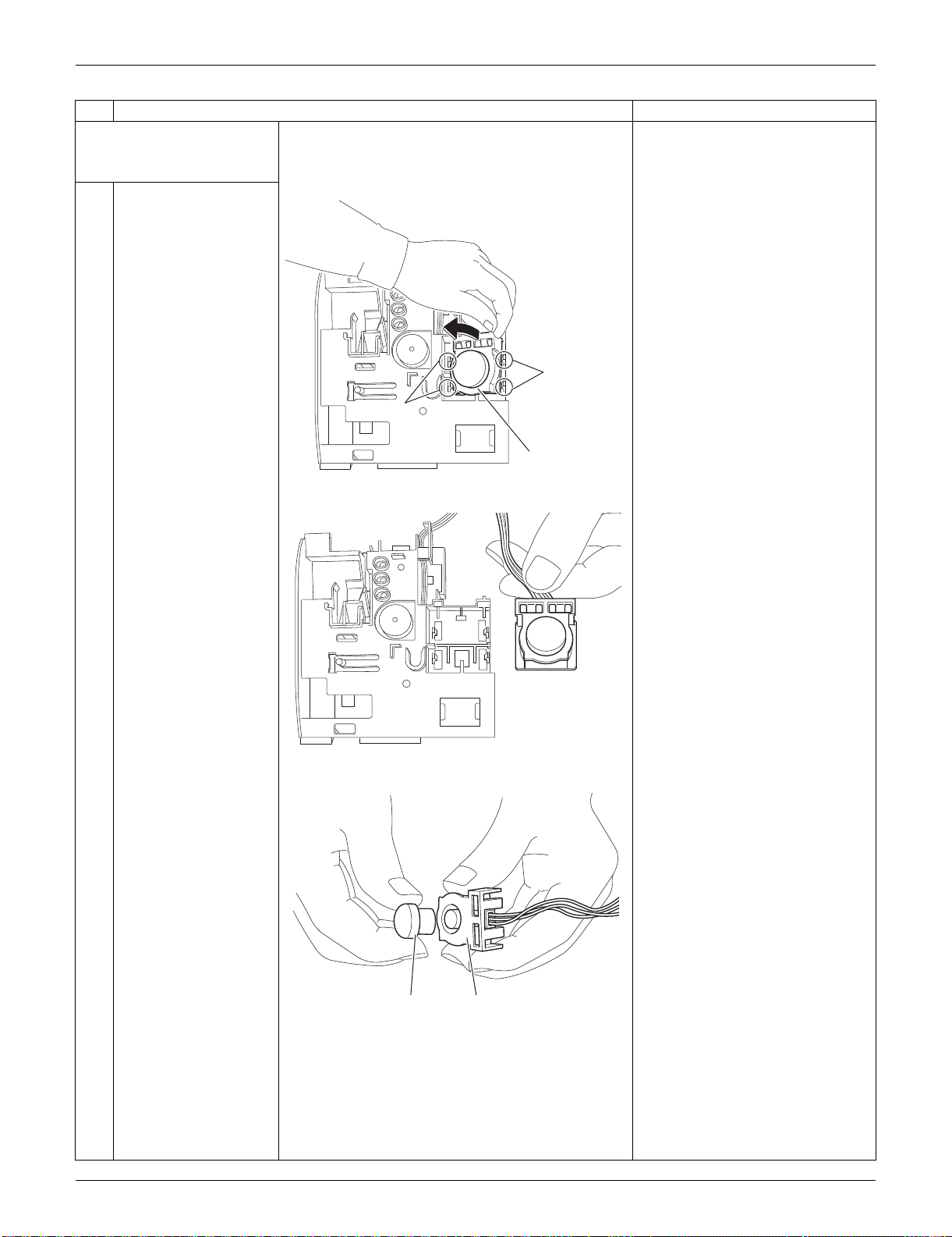
SiUS091133 Indoor Unit: FTXS30/36LVJU
Removal Procedure 236
2. Remove the
INTELLIGENT EYE
sensor PCB.
1
Unfasten the 2 hooks
on the right and then
the 2 hooks on the left.
Remove the
INTELLIGENT EYE
sensor ASSY.
2
Remove the sensor
from the shield plate.
When reassembling, set the
sensor at the position where it
“clicks”. Otherwise, the sensor is
not completely set.
Step
Procedure Points
(R9523)
Hook
Hook
INTELLIGENT EYE
sensor ASSY
(R9524)
(R9525)
Sensor Shield plate
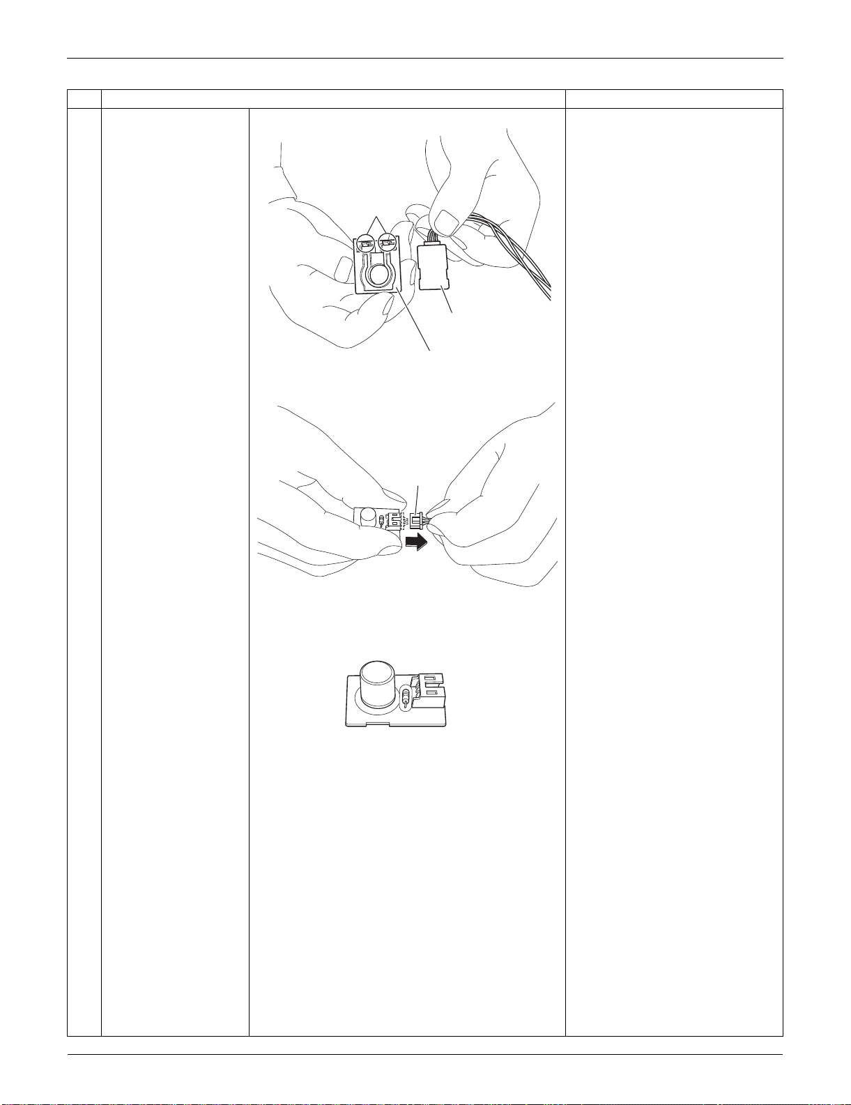
Indoor Unit: FTXS30/36LVJU SiUS091133
237 Removal Procedure
3
Remove the shield
plate by unfastening the
2 hooks.
4
Disconnect the
connector.
[S36]: control PCB
Step
Procedure Points
(R9526)
Shield plate (rear)
Hook
INTELLIGENT EYE
sensor PCB
(R9527)
[S36]
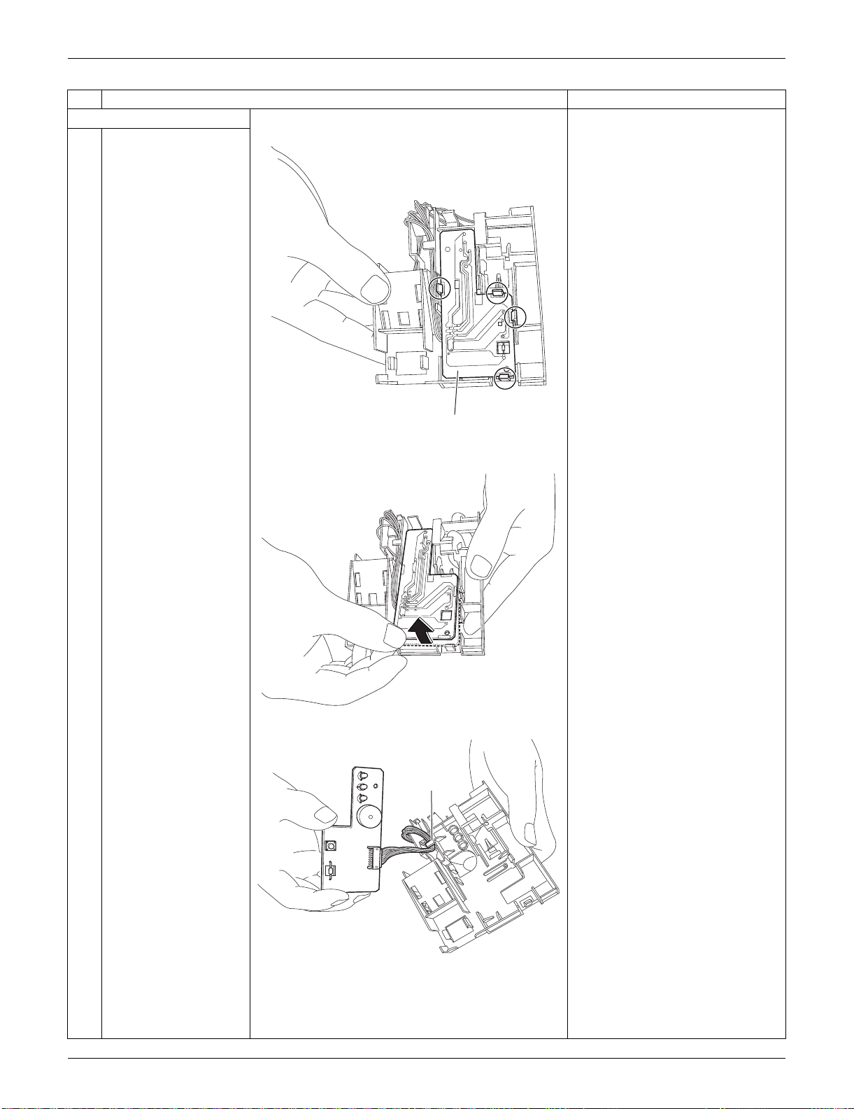
SiUS091133 Indoor Unit: FTXS30/36LVJU
Removal Procedure 238
3. Remove the display PCB.
1
Unfasten the 4 hooks.
2
Lift up the display PCB.
3
Release the harness
from the hook.
Step
Procedure Points
(R9528)
Display PCB
(R9529)
(R9530)
Hook
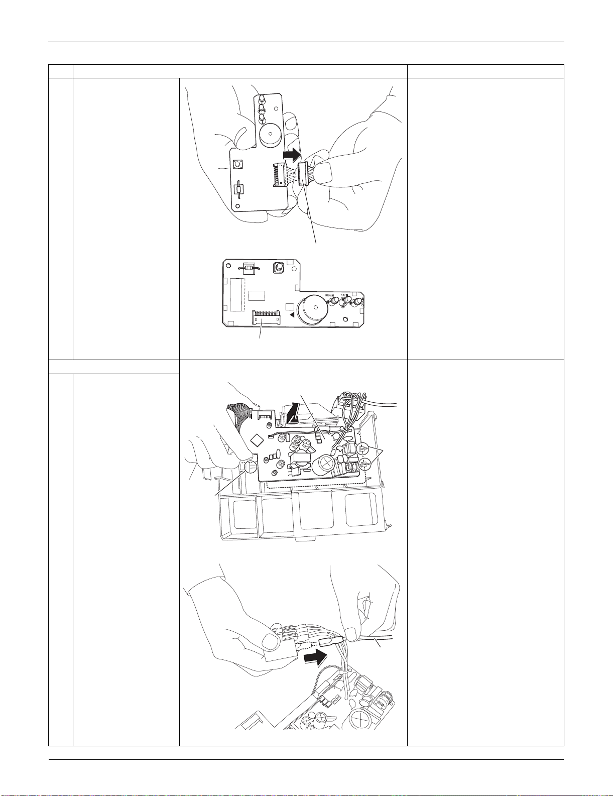
Indoor Unit: FTXS30/36LVJU SiUS091133
239 Removal Procedure
4
Disconnect the
connector.
[S49]: control PCB
4. Remove the control PCB.
1
Unfasten the 3 hooks.
Lift up and remove the
control PCB.
2
Pull out the ground wire
from the terminal board.
Step
Procedure Points
(R9531)
[S49]
3P224121-1
PbF
S49
SW1
BZ
LED1
LED2
LED3
(R13520)
[S49]
(R9517)
Hook
Hook
Control PCB
(R16550)
Ground
wire
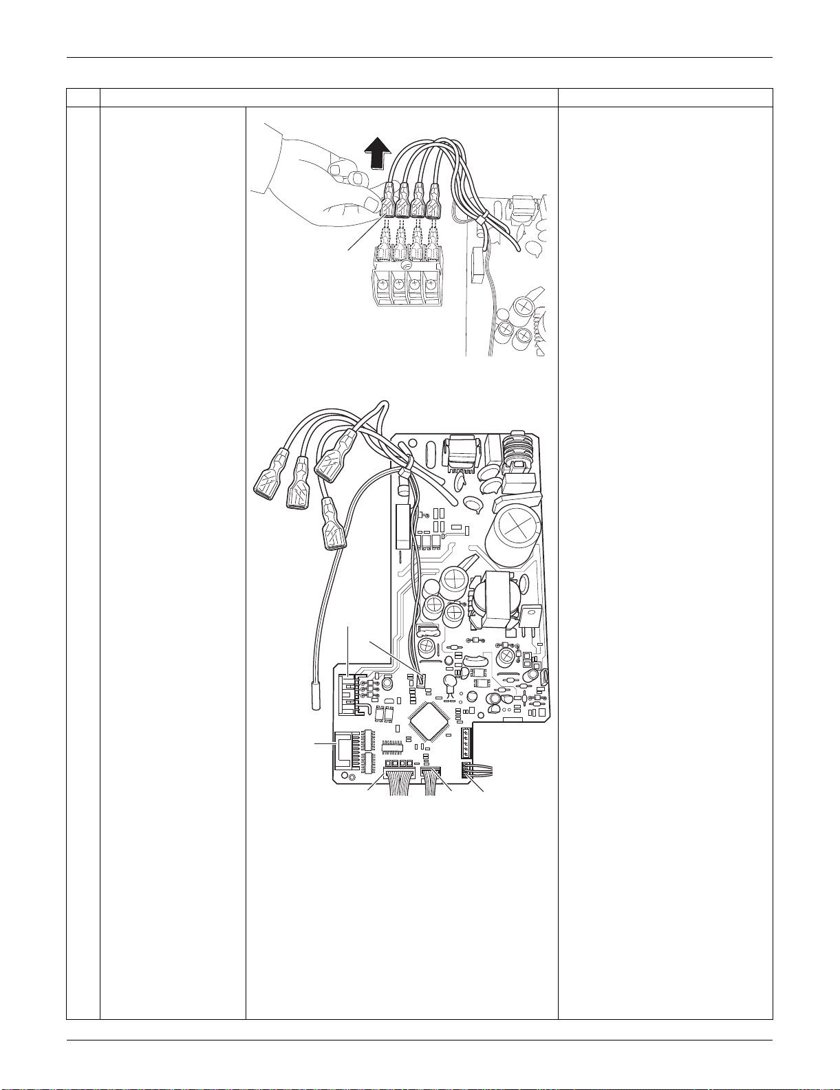
SiUS091133 Indoor Unit: FTXS30/36LVJU
Removal Procedure 240
3
Pull out the terminals
from the terminal board.
[S1] : DC fan motor
[S25] : INTELLIGENT EYE sensor
PCB
[S32] : indoor heat exchanger
thermistor
[S41] : swing motors
[S46] : display PCB
[S47] : signal receiver PCB
Refer to page 17 for detail.
Step
Procedure Points
(R9519)
Terminal
(R17047)
[S1]
[S32]
[S41]
[S46]
[S25]
[S47]
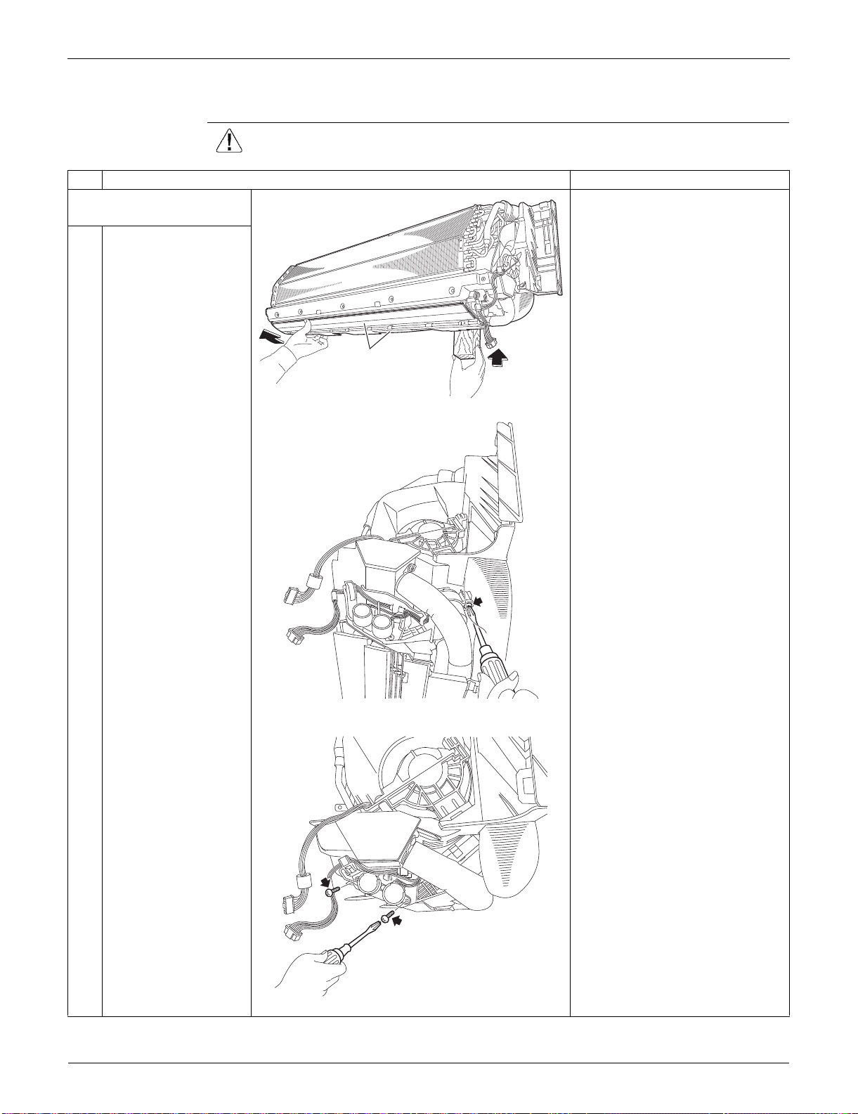
Indoor Unit: FTXS30/36LVJU SiUS091133
241 Removal Procedure
3.5 Removal of Horizontal Blades / Swing Motors
Procedure Warning Be sure to wait for 10 minutes or more after turning off all power supplies
before disassembling work.
Step
Procedure Points
1. Remove the horizontal
blades.
1
Hold the indoor unit up
with a piece of wood
etc.
2
Remove the screw at
the rear of the indoor
unit.
3
Remove the 2 screws
(front and rear).
(R9568)
Horizontal blade
(R9533)
(R9534)
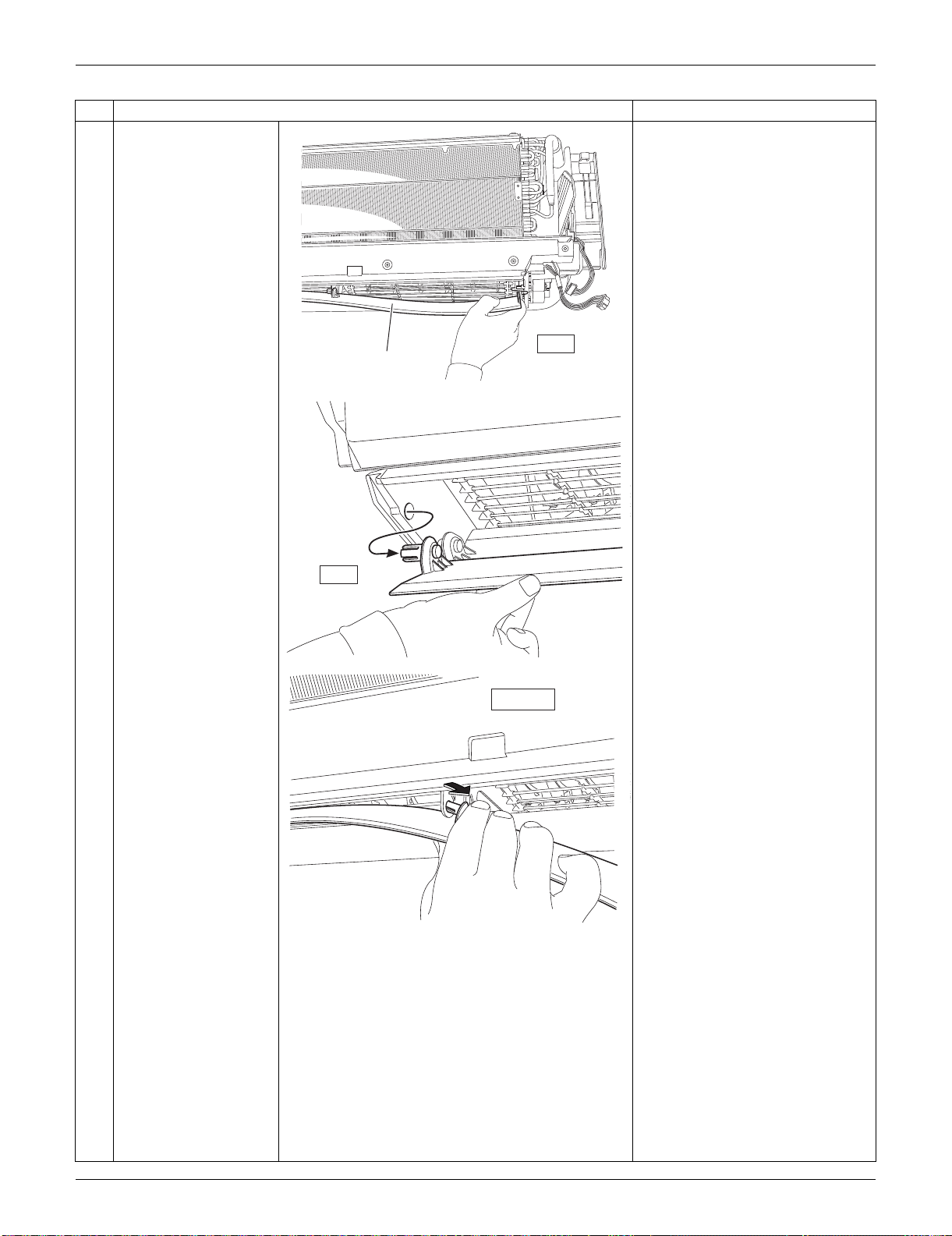
SiUS091133 Indoor Unit: FTXS30/36LVJU
Removal Procedure 242
4
Release the shafts in
turn.
Removing order
(right left
inner right
inner left)
Step
Procedure Points
right
Horizontal
blade
(R9535)
(R9536)
left
(R9537)
inner right
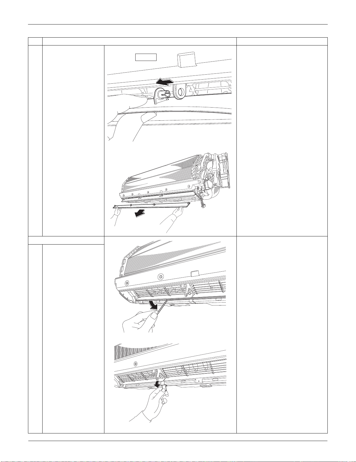
Indoor Unit: FTXS30/36LVJU SiUS091133
243 Removal Procedure
5
Remove the horizontal
blade.
Remove both the horizontal
blades (upper and lower) in the
same way.
2. Remove the fan guards.
1
Remove the sealing
material (horizontal).
2
Remove the sealing
material (vertical).
Also remove the other
sealing material on the
right.
Step
Procedure Points
inner left
(R9538)
(R9539)
(R14469)
(R14470)
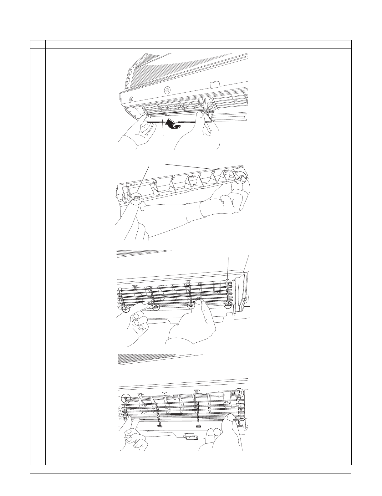
SiUS091133 Indoor Unit: FTXS30/36LVJU
Removal Procedure 244
3
Remove the left air
outlet ASSY by pushing
the 2 hooks at the back.
Remove the center and right air
outlet ASSY likewise.
4
Unfasten the 4 lower
hooks and the 2 upper
hooks and remove the
fan guard.
Remove the other 2 fan guards
likewise.
Step
Procedure Points
(R14471)
Air outlet
ASSY
(R9543)
Hook
(R9544)
Fan guard
(R9545)
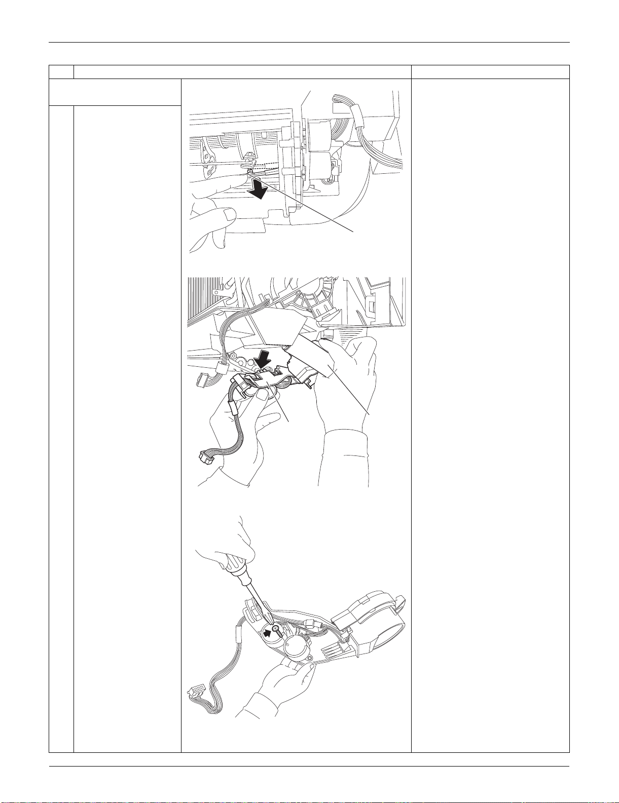
Indoor Unit: FTXS30/36LVJU SiUS091133
245 Removal Procedure
3. Remove the swing motors
for horizontal blades.
1
Release the interlock
rod.
2
Pull out the drain hose,
then remove the swing
motor unit.
3
Remove the screw at
the center.
Step
Procedure Points
(R9546)
Interlock rod
(R13579)
Drain hose
Swing motor
unit
(R9548)
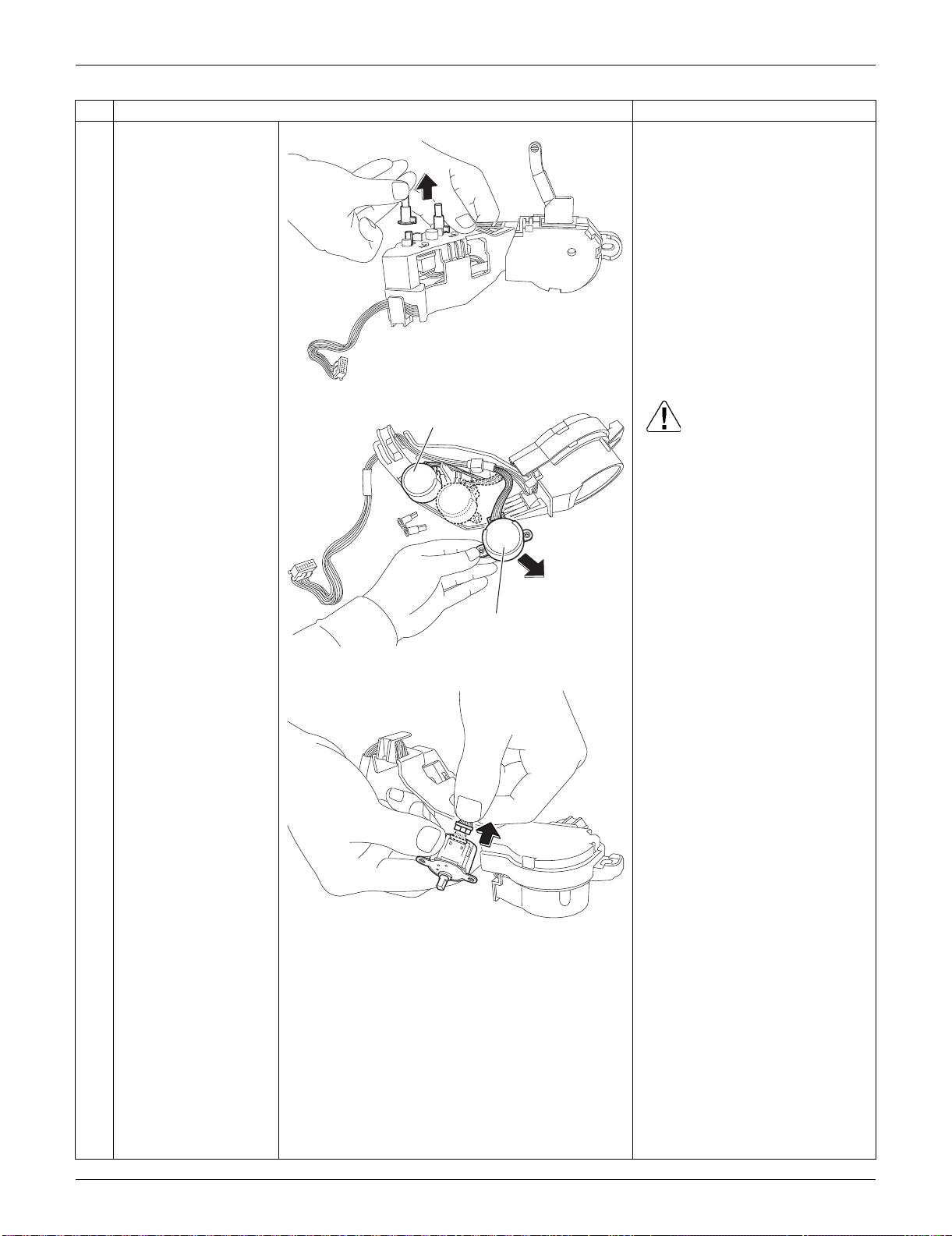
SiUS091133 Indoor Unit: FTXS30/36LVJU
Removal Procedure 246
4
Remove the 2 pivots.
5
Remove the swing
motors. Caution
When reassembling, do not
confuse the installing order of
the 2 motors and the colors of
the connectors.
If you set the connectors or
motors opposite, the horizontal
blades do not move smoothly or
the noise may be heard.
(1) Set the swing motor for the
upper blade first.
(connector: white)
(2) Then, set the swing motor for
the lower blade.
(connector: red)
(3) Fix both the swing motors with a
screw.
6
Disconnect the
connector to remove
the swing motor.
Step
Procedure Points
(R9549)
(R9550)
Swing motor (lower blade)
Swing motor (upper blade)
(R9551)
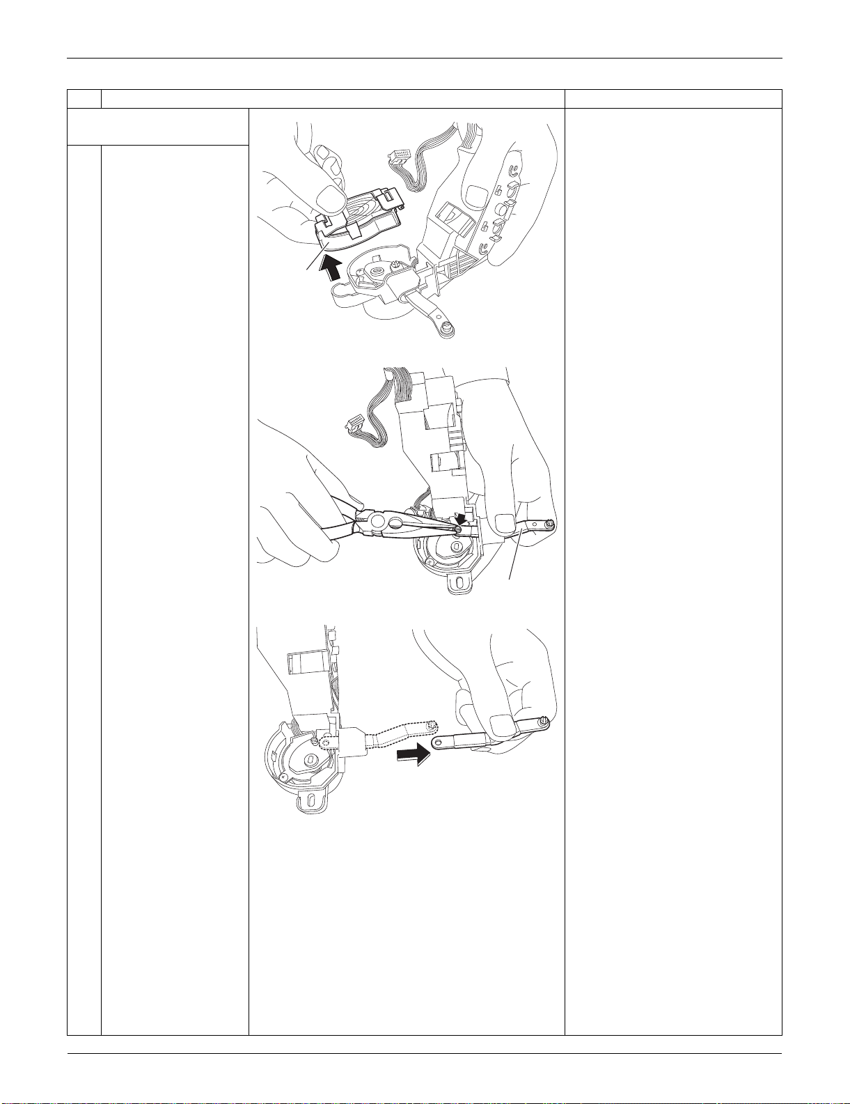
Indoor Unit: FTXS30/36LVJU SiUS091133
247 Removal Procedure
4. Remove the swing motor
for vertical blades.
1
Remove the link cover.
2
Remove the interlock
rod (2) with pliers.
Step
Procedure Points
(R9552)
Link cover
(R9553)
Interlock rod (2)
(R9554)
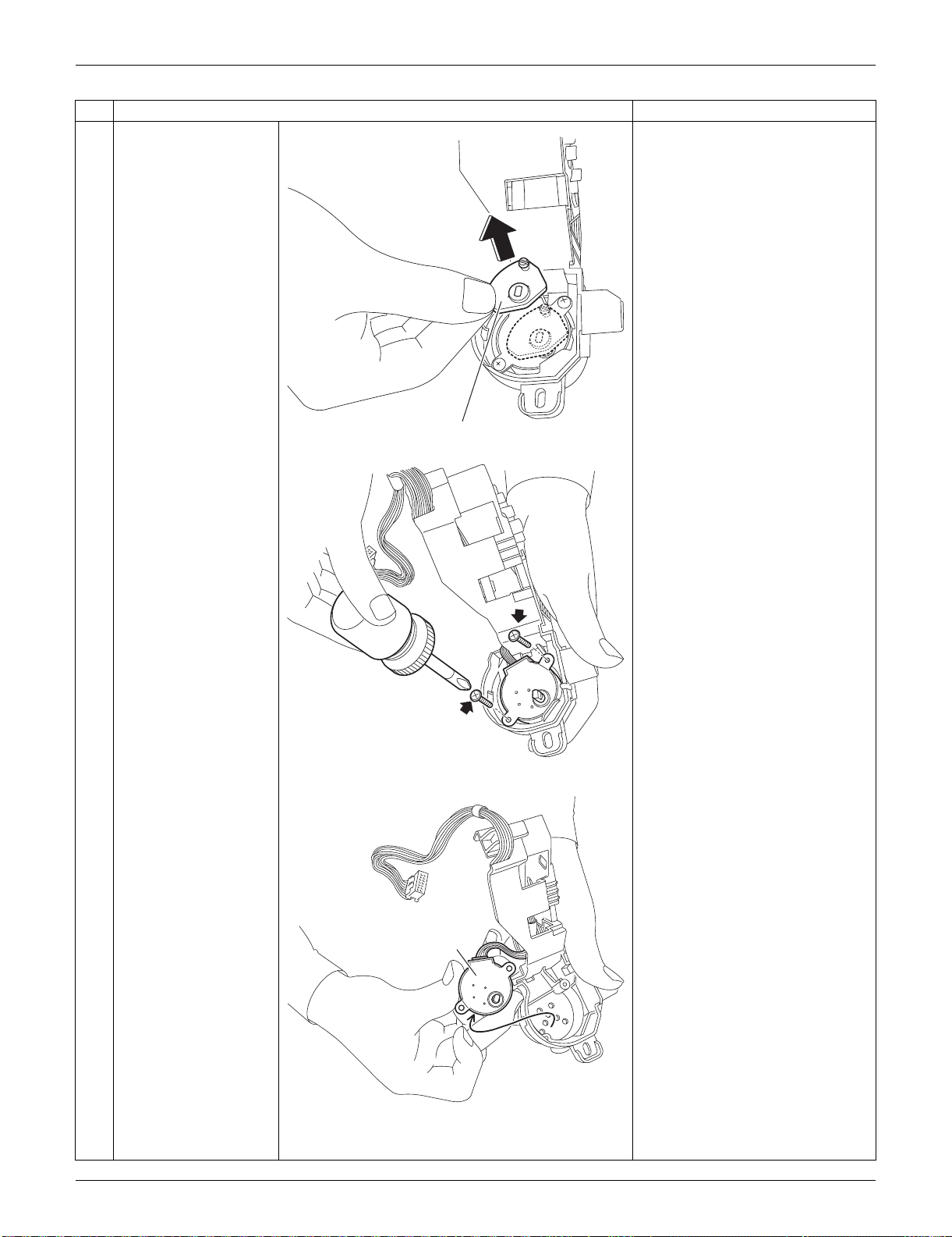
SiUS091133 Indoor Unit: FTXS30/36LVJU
Removal Procedure 248
3
Remove the interlock
rod (1).
4
Remove the 2 screws.
5
Remove the swing
motor for the vertical
blade.
Step
Procedure Points
(R9555)
Interlock rod (1)
(R9556)
(R9557)
Swing motor for
vertical blade
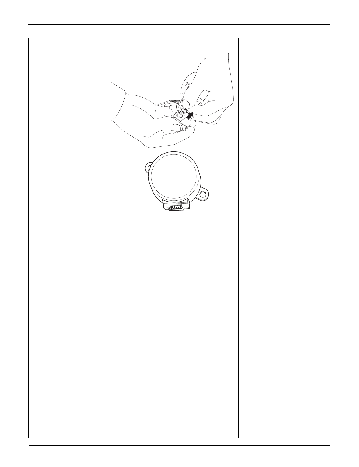
Indoor Unit: FTXS30/36LVJU SiUS091133
249 Removal Procedure
6
Disconnect the
connector.
Step
Procedure Points
(R9558)
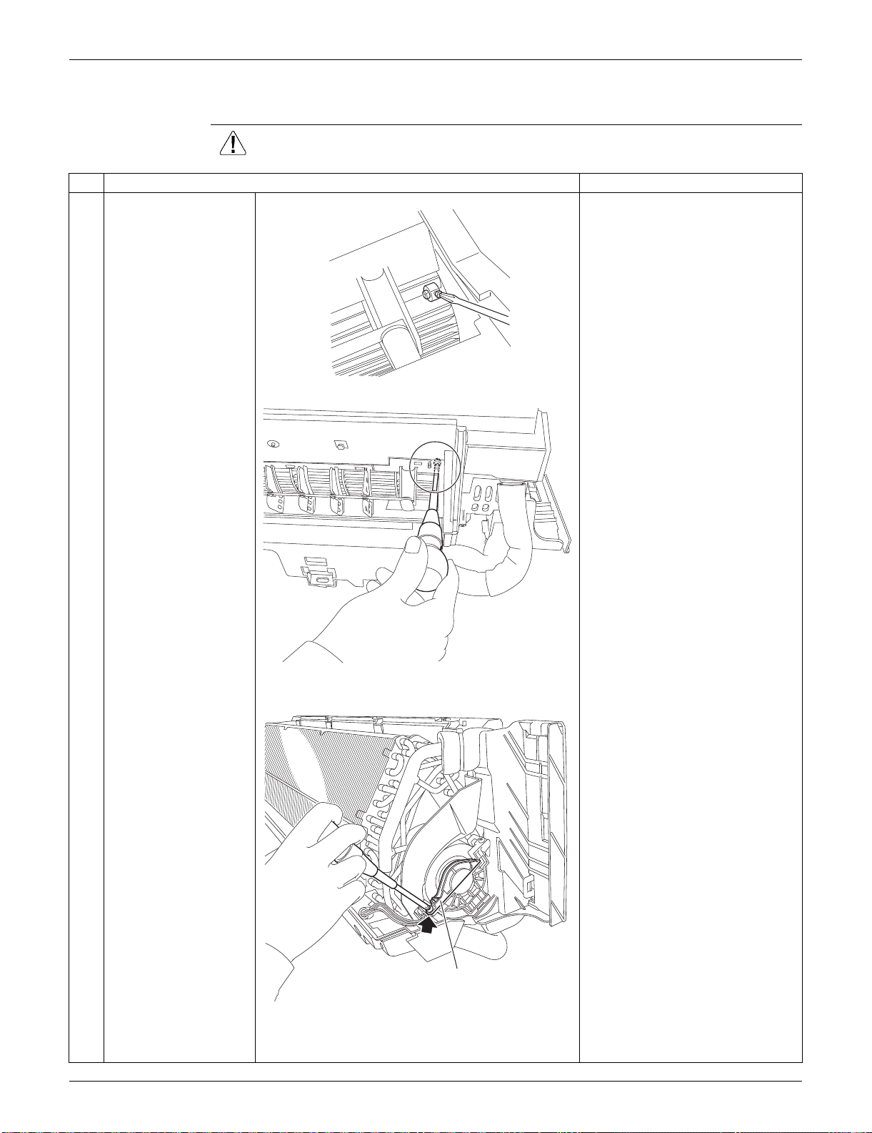
SiUS091133 Indoor Unit: FTXS30/36LVJU
Removal Procedure 250
3.6 Removal of Fan Motor
Procedure Warning Be sure to wait for 10 minutes or more after turning off all power supplies
before disassembling work.
Step
Procedure Points
1
Loosen the screw of the
fan motor from the air
outlet.
2
Remove the screw of
the fan motor fixing
plate.
(R9559)
(R9560)
Fan motor fixing plate
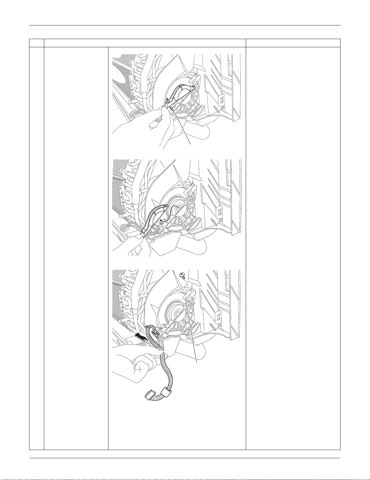
Indoor Unit: FTXS30/36LVJU SiUS091133
251 Removal Procedure
3
Unfasten the hook at
the front and remove
the fan motor fixing
plate.
4
Release the harness
from the hook, and
remove the screw of the
motor mounting plate.
Step
Procedure Points
(R9561)
Hook
(R9562)
(R9563)
Motor mounting plate
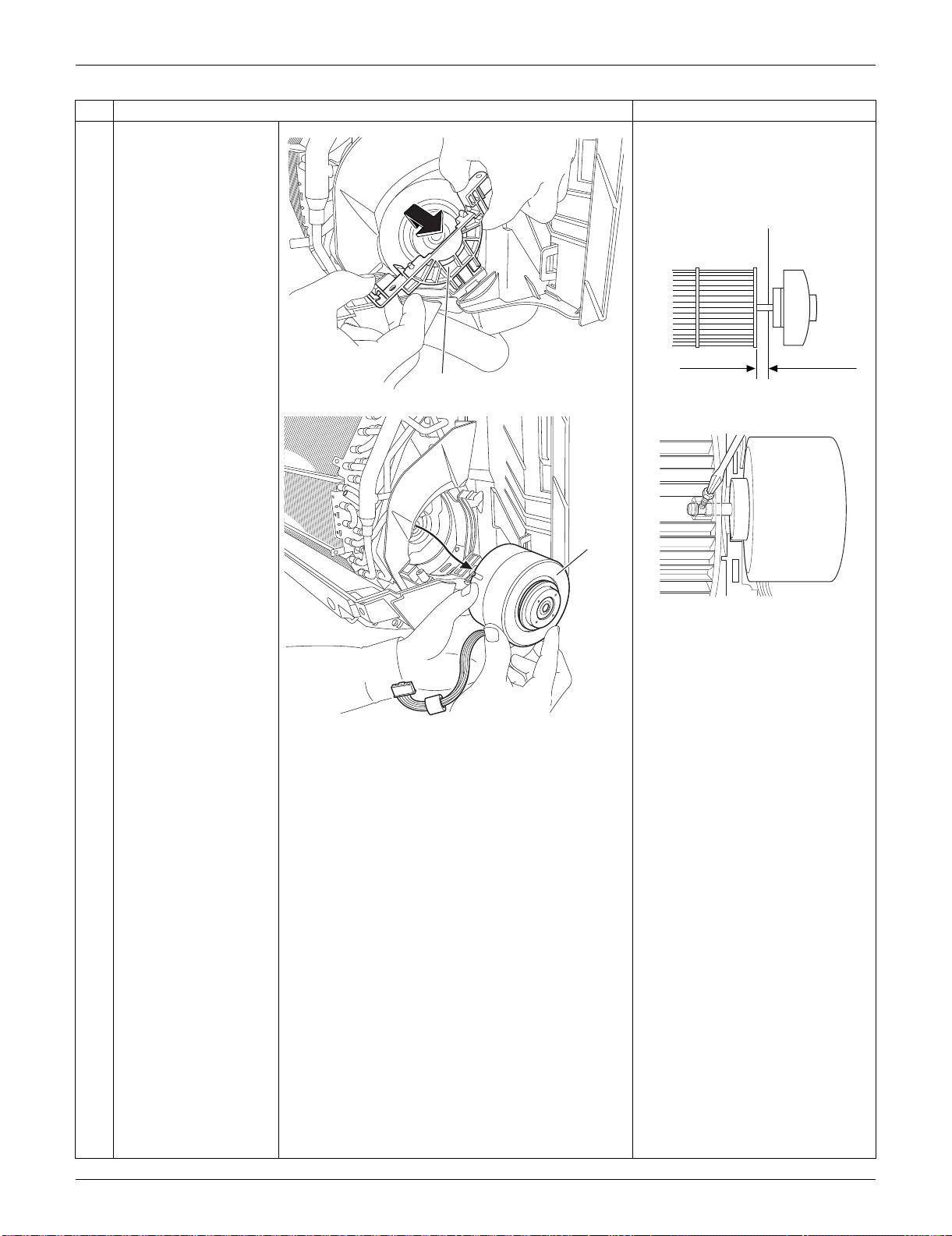
SiUS091133 Indoor Unit: FTXS30/36LVJU
Removal Procedure 252
5
Remove the motor
mounting plate.
When reassembling the fan
motor and the fan rotor, provide
as much as 5 mm (0.2 inch) of
play between the side face of
the rotor and the bottom frame.
(1) Insert the fan motor with approx.
5 mm (0.2 inch) left.
(2) Tighten the screw until it stops.
Then give the screw one more
turn.
(3) Rotate the fan rotor and confirm
the fan motor and the fan rotor
are installed appropriately.
(4) Tighten the screw completely if
appropriate.
(5) If not appropriate, go back to
(1).
6
Remove the fan motor.
Step
Procedure Points
(R9564)
Motor mounting plate
5 mm (0.2 inch)
Side face of rotor
(R2808)
Side face of
bottom frame
(R9582)
(R9565)
Fan motor
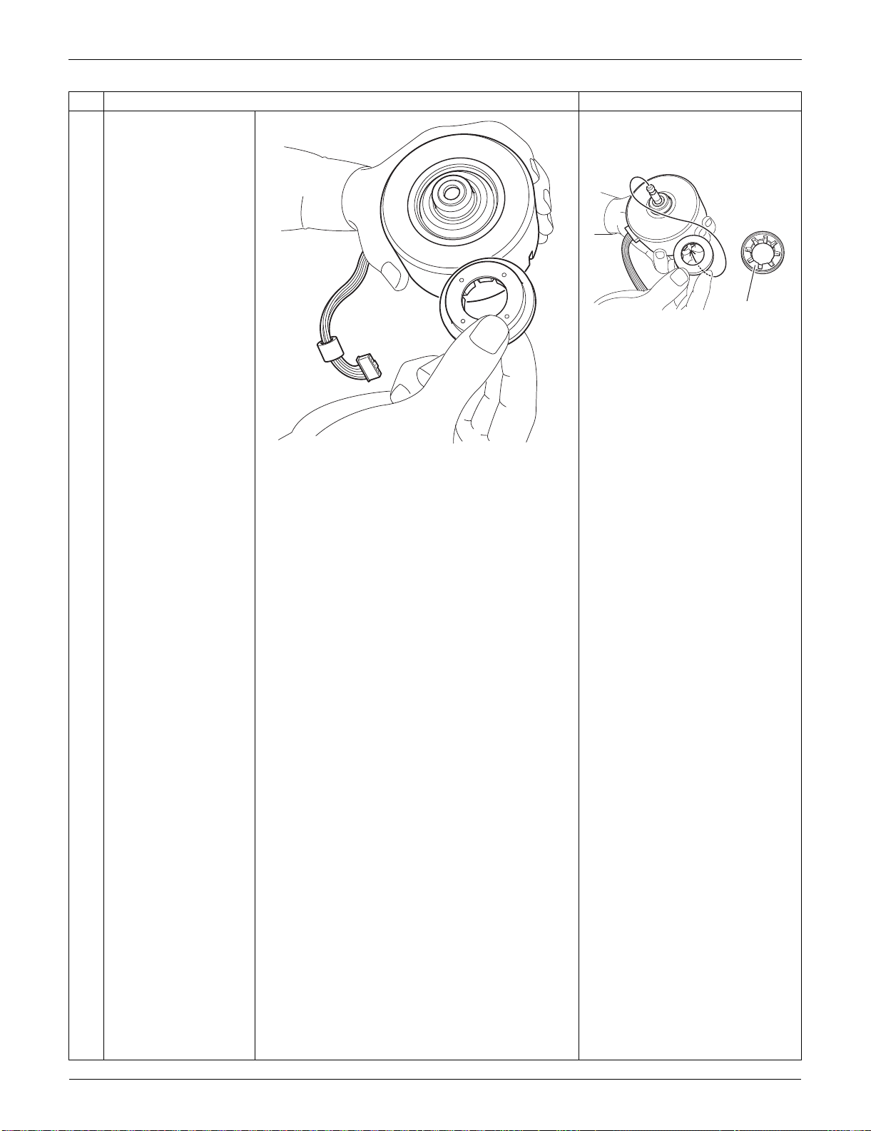
Indoor Unit: FTXS30/36LVJU SiUS091133
253 Removal Procedure
7
Remove the vibration
absorber.
When reassembling, engage
the vibration absorber
completely.
Step
Procedure Points
(R9567)
(R9566)
Vibration
absorber
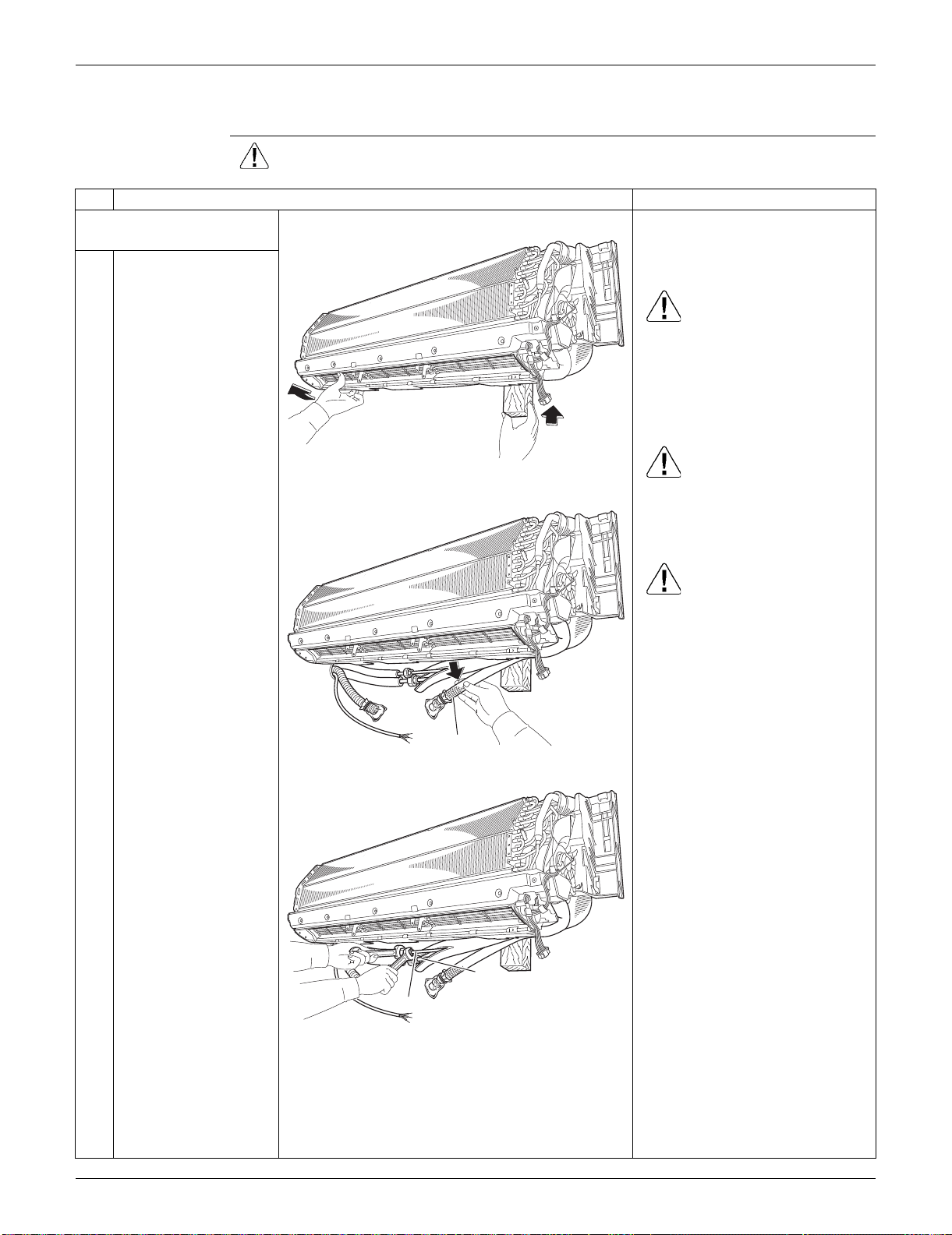
SiUS091133 Indoor Unit: FTXS30/36LVJU
Removal Procedure 254
3.7 Removal of Indoor Heat Exchanger
Procedure Warning Be sure to wait for 10 minutes or more after turning off all power supplies
before disassembling work.
Step
Procedure Points
1. Disconnect the refrigerant
piping.
Preparation
Remove the electrical box
according to the “Removal of
Electrical Box”.
Caution
If the refrigerant leaks, repair the
leakage, then collect all
refrigerant from the unit. After
conducting vacuum drying,
recharge a proper amount of
refrigerant.
Caution
From the viewpoint of global
environment protection, be sure
to use a vacuum pump for air
purging.
Caution
In pump-down work, be sure to
stop the compressor before
disconnecting the refrigerant
piping. If the refrigerant piping is
disconnected with the
compressor operating and the
stop valve open, air may be
sucked in to generate an over-
pressure in refrigeration cycle,
thus resulting in pipe rupture or
accidental injury.
Place a plastic sheet under the
drain pan to prevent from
wetting the floor with remaining
drain.
If the drain hose is embedded in
the wall, disconnect the drain
hose beforehand.
Carry out the removal work with
2 wrenches.
When the pipings are
disconnected, protect both the
openings of pipe and unit from
entering moisture.
1
Hold the indoor unit up
with a piece of wood
etc.
2
Pull out the drain hose.
3
Unscrew the flare nuts
for gas piping and liquid
piping.
(R11406)
(R9569)
Drain hose
(R9570)
Liquid piping
Gas piping
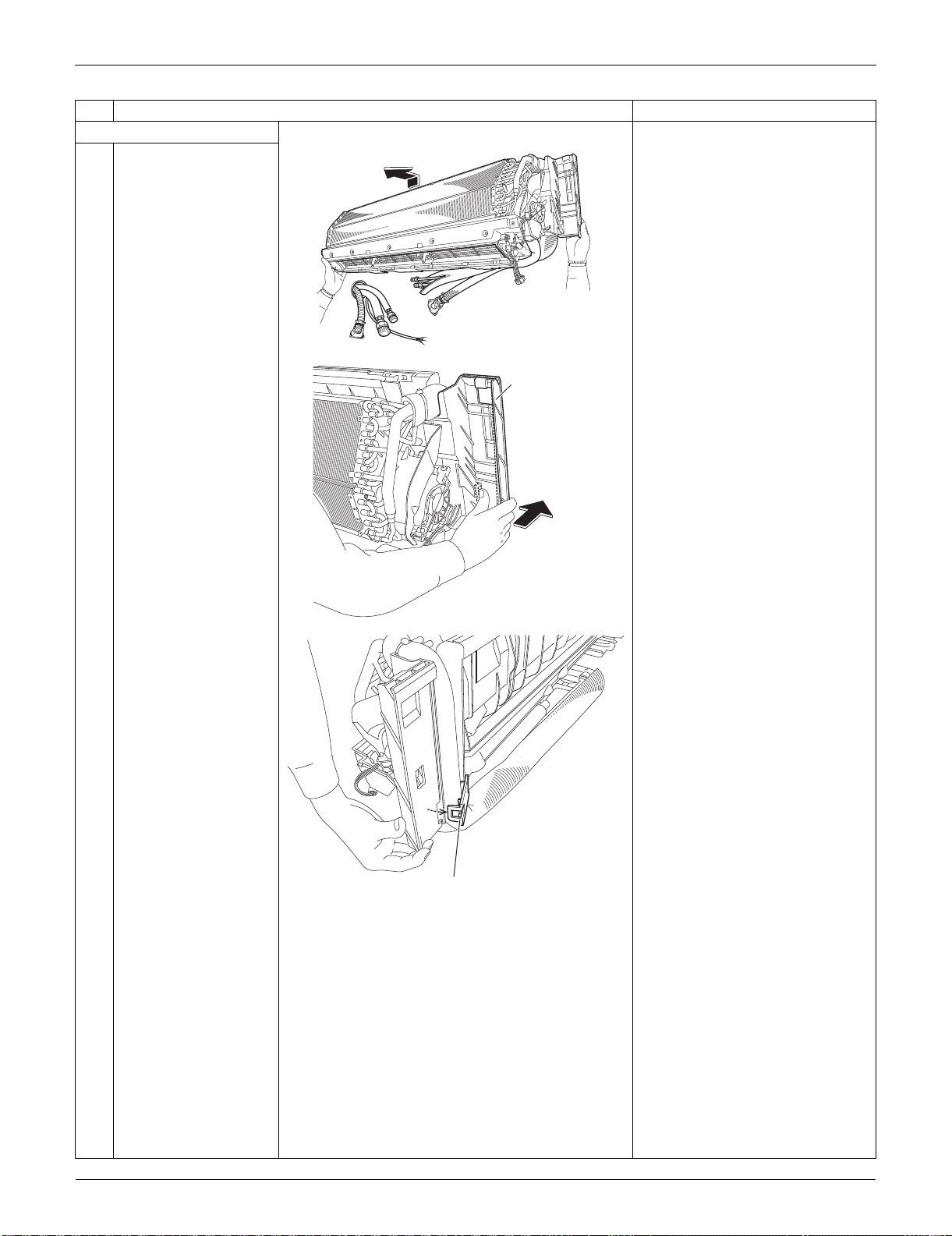
Indoor Unit: FTXS30/36LVJU SiUS091133
255 Removal Procedure
2. Remove the piping fixture.
1
Detach the indoor unit
from the installation
plate.
2
Push the bottom frame.
3
Release the piping
fixture.
Step
Procedure Points
(R9571)
(R9572)
Bottom frame
(R9573)
Piping fixture
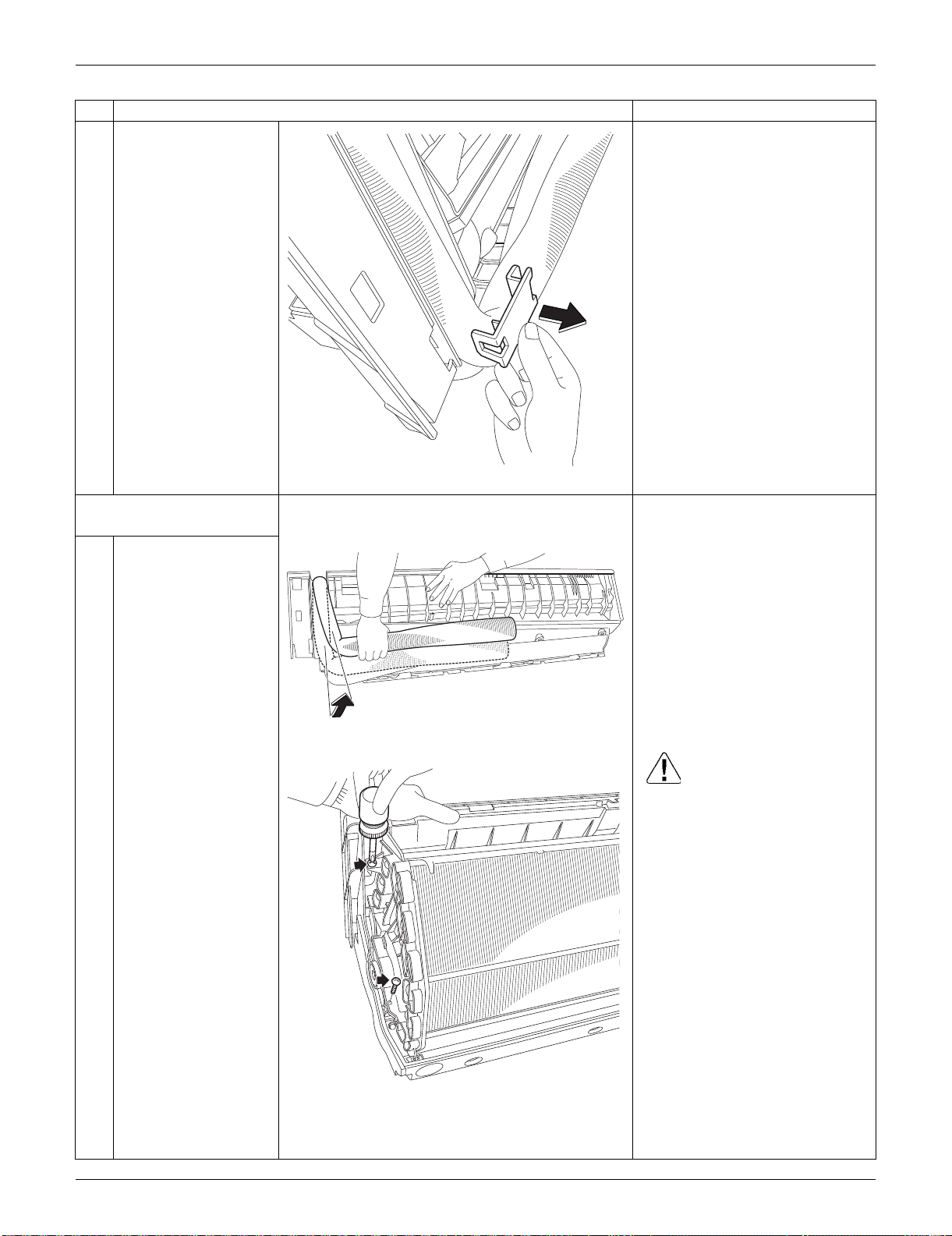
SiUS091133 Indoor Unit: FTXS30/36LVJU
Removal Procedure 256
4
Remove the piping
fixture.
3. Remove the indoor heat
exchanger.
1
Widen the auxiliary
piping.
2
Remove the 2 screws
on the left side. Caution
When removing or reassembling
the indoor heat exchanger, be
sure to wear gloves or wrap the
indoor heat exchanger with
cloths. (You may be injured by
the fins.)
Step
Procedure Points
(R9574)
(R9575)
(R13580)
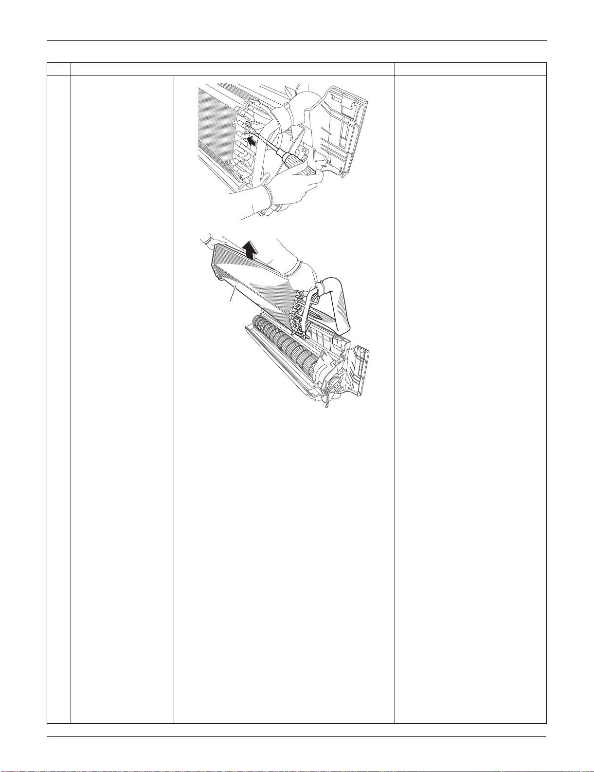
Indoor Unit: FTXS30/36LVJU SiUS091133
257 Removal Procedure
3
Push the hook on the
right side and unfasten
it.
4
Lift up and remove the
indoor heat exchanger.
Press the right side of the indoor
heat exchanger, and lift it up
from the left side.
Step
Procedure Points
(R13581)
(R9578)
Indoor heat
exchanger
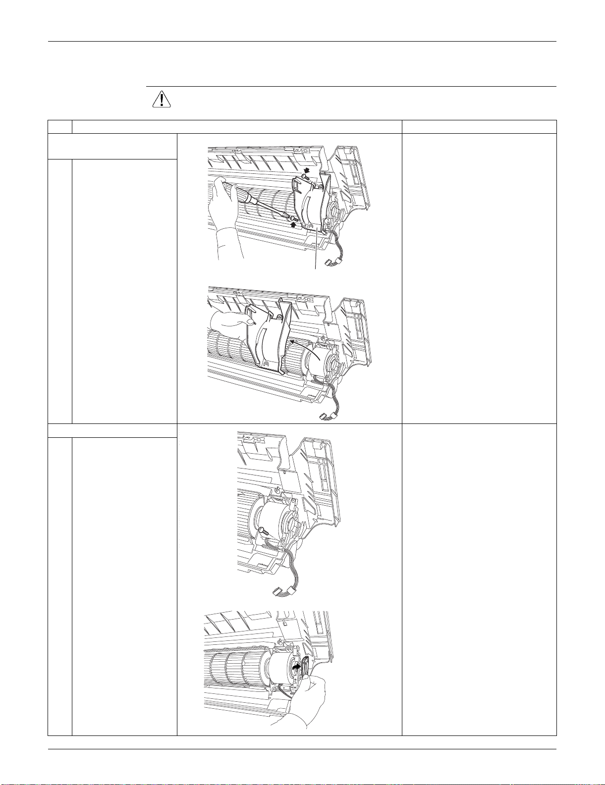
SiUS091133 Indoor Unit: FTXS30/36LVJU
Removal Procedure 258
3.8 Removal of Fan Rotor
Procedure Warning Be sure to wait for 10 minutes or more after turning off all power supplies
before disassembling work.
Step
Procedure Points
1. Remove the right side
plate.
1
Remove the 2 screws.
2
Lift the right side plate
and remove it.
2. Remove the fan rotor.
1
Remove the screw of
the fan motor fixing
plate.
2
Remove the fan motor
fixing plate.
(R9579)
Right side plate
(R9580)
(R17121)
(R9581)
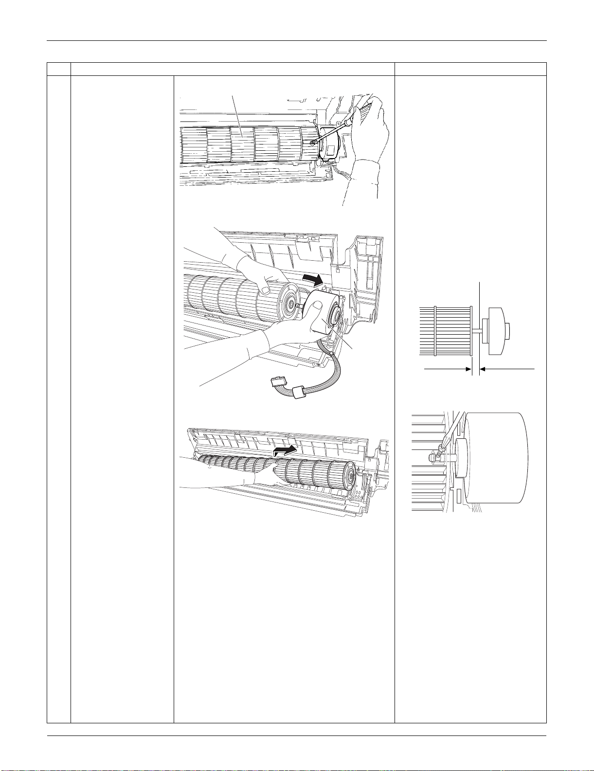
Indoor Unit: FTXS30/36LVJU SiUS091133
259 Removal Procedure
3
Loosen the screw of the
fan rotor.
4
Remove the fan motor. When reassembling the fan
motor and the fan rotor, provide
as much as 5 mm (0.2 inch) of
play between the side face of
the rotor and the bottom frame.
(1) Insert the fan motor with approx.
5 mm (0.2 inch) left.
(2) Tighten the screw until it stops.
Then give the screw one more
turn.
(3) Rotate the fan rotor and confirm
the fan motor and the fan rotor
are installed appropriately.
(4) Tighten the screw completely if
appropriate.
(5) If not appropriate, go back to
(1).
5
Remove the fan rotor.
Step
Procedure Points
Fan rotor
(R9648)
(R9583)
Fan motor
5 mm (0.2 inch)
Side face of rotor
(R2808)
Side face of
bottom frame
(R9582)
(R9584)
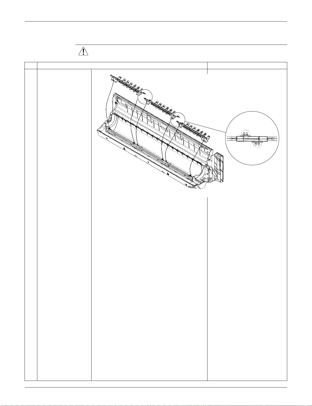
SiUS091133 Indoor Unit: FTXS30/36LVJU
Removal Procedure 260
3.9 Removal of Vertical Blade ASSYs
Procedure Warning Be sure to wait for 10 minutes or more after turning off all power supplies
before disassembling work.
Step
Procedure Points
Unfasten the 2 hooks of
each vertical blade
ASSY.
Remove the 3 vertical
blade ASSYs.
Each vertical blade ASSY is
united with a drain pan ASSY.
(R16979)
When reassembling,
connect the 3 vertical blade
ASSYs. Fasten the hooks at
the connecting points.
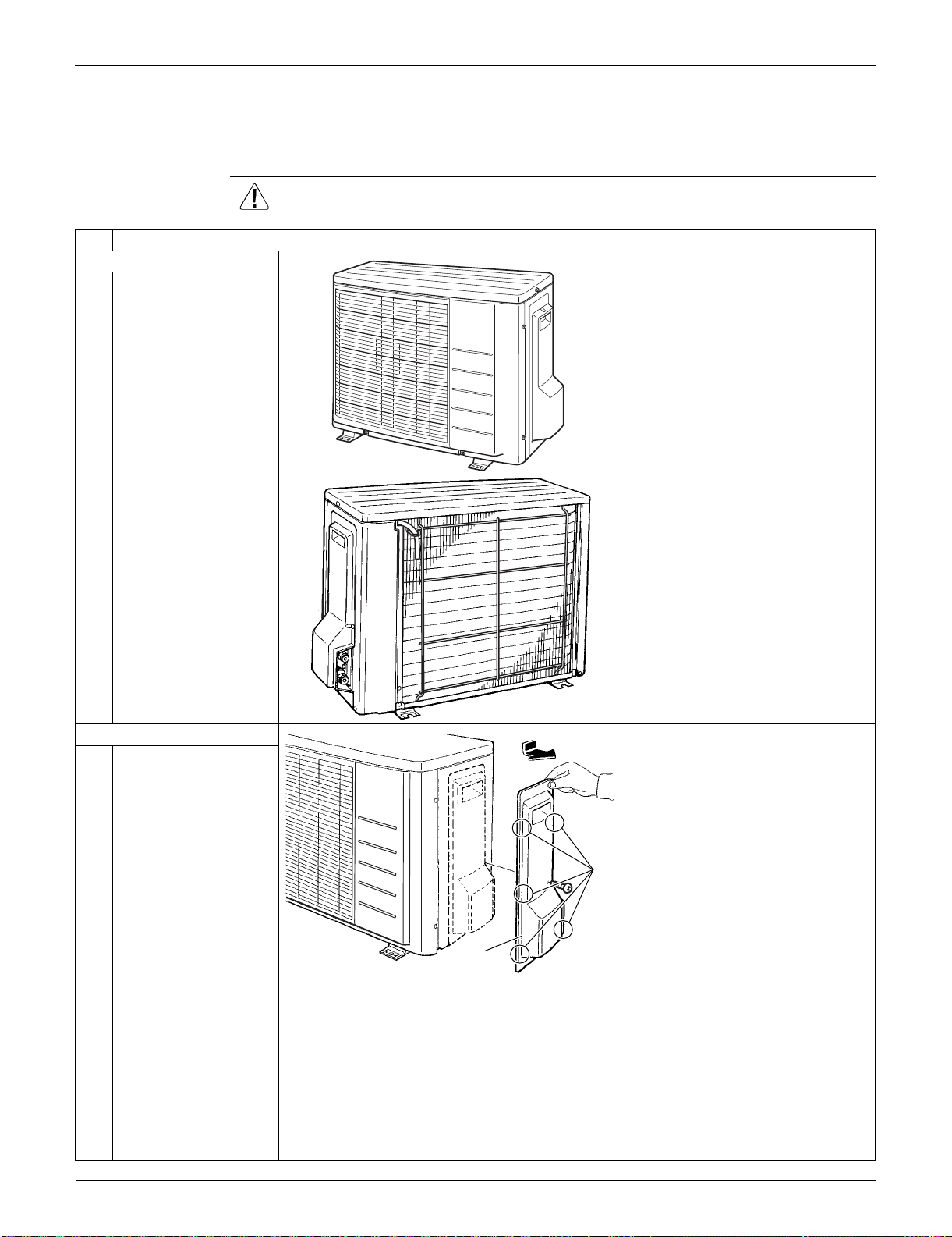
Outdoor Unit: RXS09/12LVJU SiUS091133
261 Removal Procedure
4. Outdoor Unit: RXS09/12LVJU
4.1 Removal of Outer Panels / Fan Motor
Procedure Warning Be sure to wait for 10 minutes or more after turning off all power supplies
before disassembling work.
Step
Procedure Points
1. Appearance features
Take care not to cut your finger
by the fins of the outdoor heat
exchanger.
2. Remove the panels. When reassembling, make sure
to fit the 5 hooks.
1
Remove the screw of
the stop valve cover.
Pull the stop valve
cover downward and
remove it.
(R7186)
(R16044)
Stop valve
cover
Hook
(R16977)

SiUS091133 Outdoor Unit: RXS09/12LVJU
Removal Procedure 262
2
Remove the 3 screws
and lift the top panel.
3
Remove the drip proof
cover.
4
Remove the 4 screws
and remove the
discharge grille.
Step
Procedure Points
Top panel
(R16978)
Drip proof cover
(R16980)
Discharge
grille
(R16981)
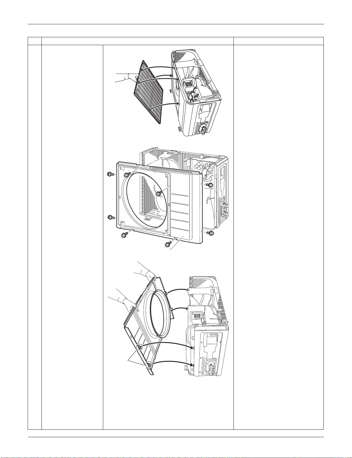
Outdoor Unit: RXS09/12LVJU SiUS091133
263 Removal Procedure
The discharge grille has 4
hooks.
5
Remove the 8 screws
of the front panel.
6
Unfasten the hooks.
Pull and remove the
front panel.
The front panel has 4 hooks.
Step
Procedure Points
(R16982)
Front panel
(R16983)
Hook
(R16984)
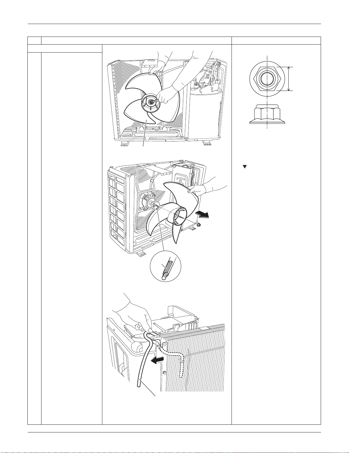
SiUS091133 Outdoor Unit: RXS09/12LVJU
Removal Procedure 264
3. Remove the fan motor. Nut size: M6
1
Remove the nut of the
outdoor fan.
2
Remove the outdoor
fan.
When reassembling, align the
mark of the outdoor fan with
the D-cut section of the motor
shaft.
3
Release the outdoor
temperature thermistor.
Step
Procedure Points
Outdoor fan
(R16922)
10 mm
(0.39 inch)
(R16985)
D-cut
(R11828)
Outdoor temperature
thermistor
(R16986)
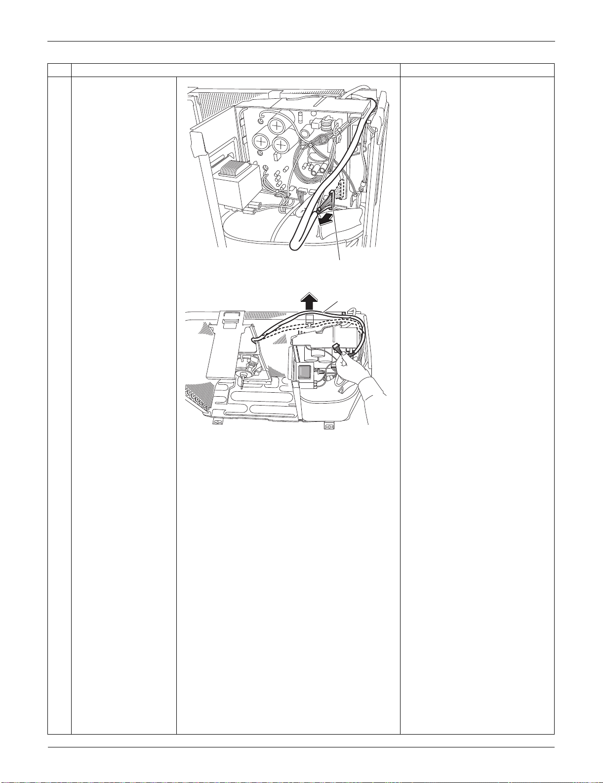
Outdoor Unit: RXS09/12LVJU SiUS091133
265 Removal Procedure
4
Disconnect the
connector for the fan
motor [S70].
5
Release the fan motor
lead wire from the hook.
Step
Procedure Points
[S70]
(R16987)
Fan motor
lead wire
(R11832)
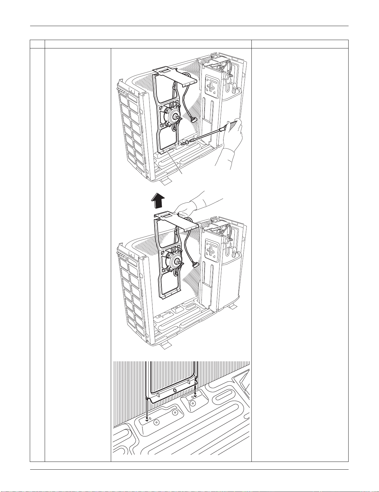
SiUS091133 Outdoor Unit: RXS09/12LVJU
Removal Procedure 266
6
Remove the screw and
remove the fan motor
fixing frame.
When reassembling, fit the
lower hooks into the bottom
frame.
Step
Procedure Points
Fan motor fixing frame
(R11833)
(R12314)
(R7206)
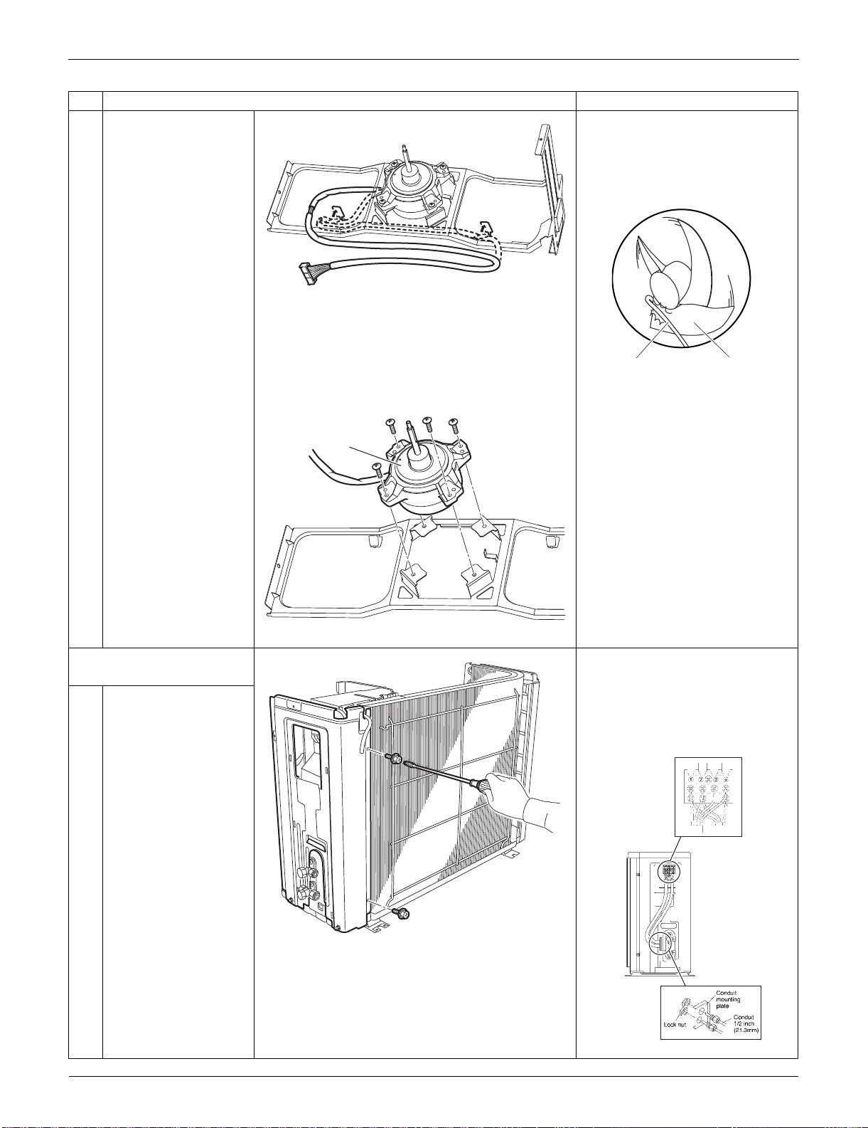
Outdoor Unit: RXS09/12LVJU SiUS091133
267 Removal Procedure
7
Open the 2 hooks and
release the fan motor
lead wire.
When reassembling, put the fan
motor lead wire through the
back of the fan motor so as not
to be entangled with the outdoor
fan.
8
Remove the 4 screws
and remove the fan
motor.
4. Remove the right side
panel.
When reassembling, pass the
connecting wires through the
conduit and secure them with a
lock nut.
Remove the screws and detach
the connection wires.
1
Remove the 2 screws
on the rear side.
Step
Procedure Points
(R11835)
(R3249)
Lead wire Outdoor fan
Fan motor
(R12311)
(R16988)
(R16989)
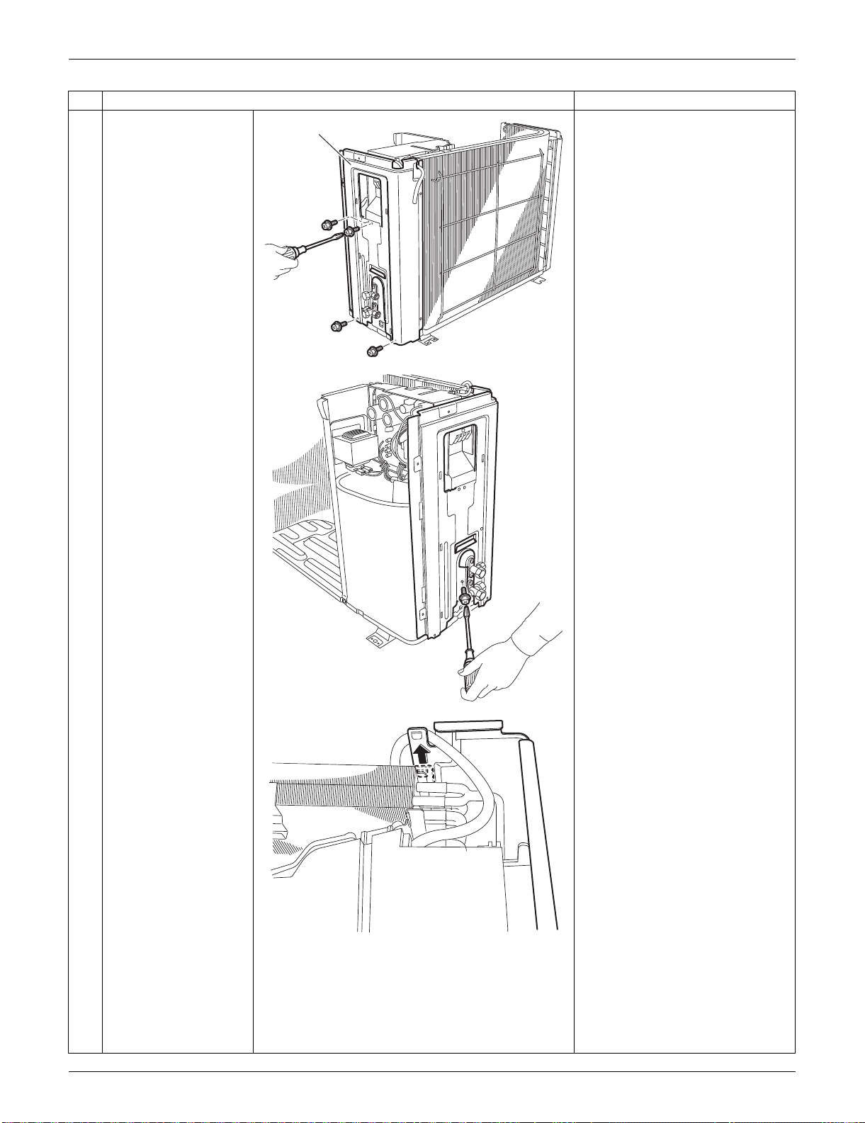
SiUS091133 Outdoor Unit: RXS09/12LVJU
Removal Procedure 268
2
Remove the 4 screws
on the right side panel.
3
Remove the screw near
the stop valves.
4
Unfasten the hook on
the rear side.
When reassembling, make sure
to fit the hook.
Step
Procedure Points
Right side panel
(R16990)
(R16991)
(R11842)
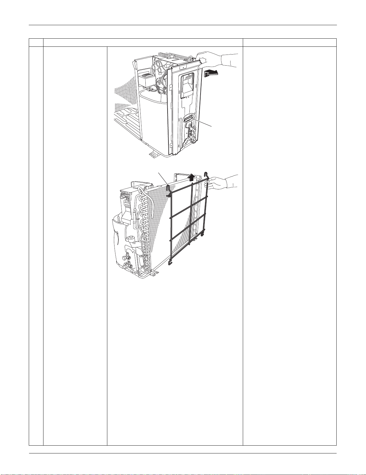
Outdoor Unit: RXS09/12LVJU SiUS091133
269 Removal Procedure
5
Lift up the right side
panel and remove it.
When reassembling, make sure
to fit the hook.
6
Lift up the guard net
and remove it.
Step
Procedure Points
Hook
(R16992)
Guard net
(R16993)
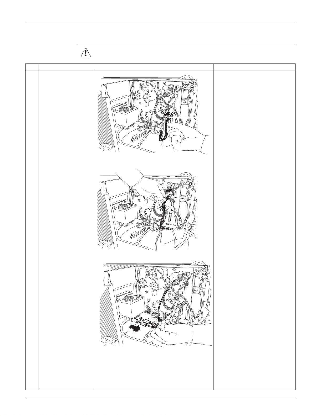
SiUS091133 Outdoor Unit: RXS09/12LVJU
Removal Procedure 270
4.2 Removal of Electrical Box
Procedure Warning Be sure to wait for 10 minutes or more after turning off all power supplies
before disassembling work.
Step
Procedure Points
1
Disconnect the
connector for the
overload protector
[S40].
Preparation
Remove the outer panels and
disconnect the connector for the
fan motor according to the
“Removal of Outer Panels / Fan
Motor”.
2
Disconnect the
connector for the four-
way valve coil [S80].
3
Disconnect the 2
connectors for the
reactor.
When reassembling, you can
connect the 2 harnesses in
either way regardless of the
color.
[S40]
(R16924)
[S80]
(R16925)
(R16926)
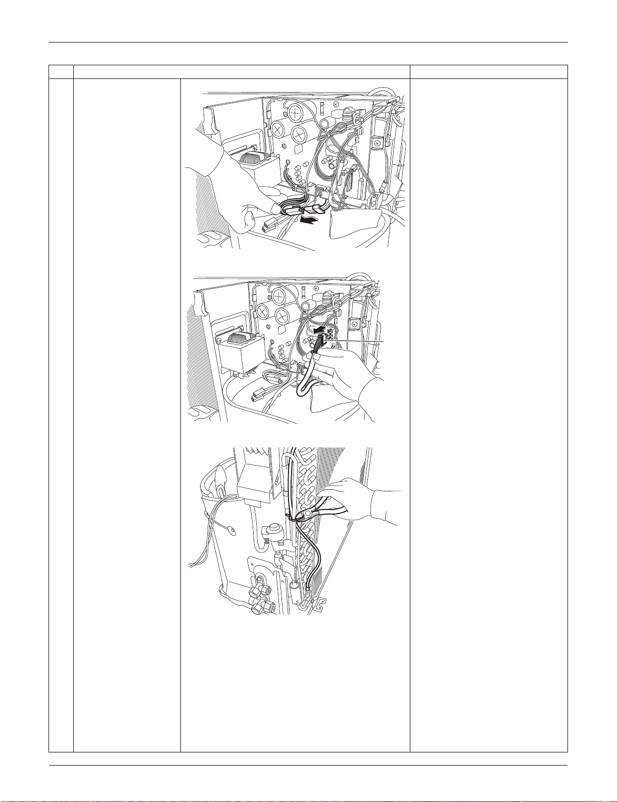
Outdoor Unit: RXS09/12LVJU SiUS091133
271 Removal Procedure
4
Disconnect the relay
connector for the
compressor.
5
Disconnect the
connector for the
electronic expansion
valve coil [S20].
6
Cut the clamp.
Step
Procedure Points
(R16927)
[S20]
(R16928)
(R16994)
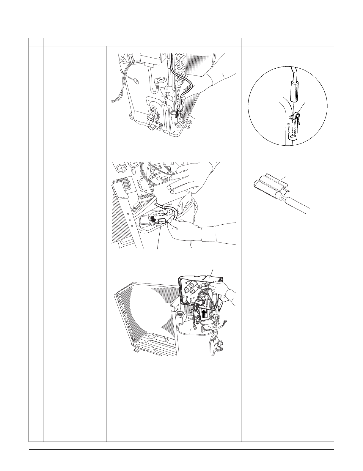
SiUS091133 Outdoor Unit: RXS09/12LVJU
Removal Procedure 272
7
Pull out the outdoor
heat exchanger
thermistor.
Be careful not to lose the clip for
the thermistor.
8
Release the discharge
pipe thermistor.
Be careful not to lose the clip for
the thermistor.
9
Lift and remove the
electrical box.
Step
Procedure Points
Outdoor heat
exchanger thermistor
(R16995)
Clip
(R3264)
Discharge pipe thermistor
(R11849)
(R12279)
Clip
Electrical Box
(R16996)
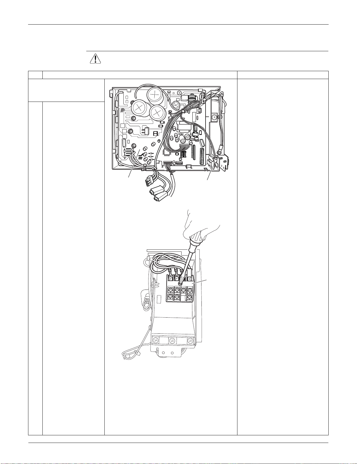
Outdoor Unit: RXS09/12LVJU SiUS091133
273 Removal Procedure
4.3 Removal of PCBs
Procedure Warning Be sure to wait for 10 minutes or more after turning off all power supplies
before disassembling work.
Step
Procedure Points
1. Remove the main PCB
and the forced operation
button PCB.
You can remove the main PCB
when you disconnect the lead
wires on the terminal board
without removing the electrical
box.
1
Layout of the main PCB
2
Remove the screw on
the terminal board.
Main PCB
Forced operation
button PCB
(R16997)
Terminal
board
(R11854)
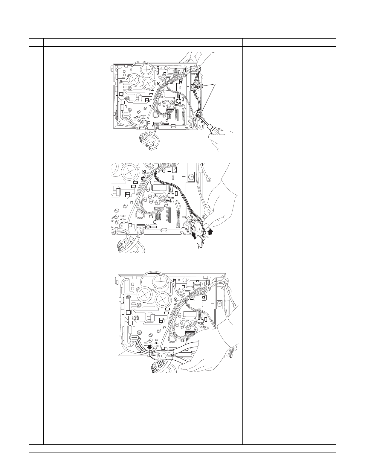
SiUS091133 Outdoor Unit: RXS09/12LVJU
Removal Procedure 274
3
Release the 2 ground
wires.
4
Pull out the forced
operation button PCB.
Disconnect the
connector [S110] to
remove the forced
operation button PCB.
Be careful of a sharp protrusion
at the back of the forced
operation button PCB.
5
Cut the clamp.
Step
Procedure Points
Ground
wire
(R16998)
Forced operation button PCB
[S110]
(R16932)
(R16933)
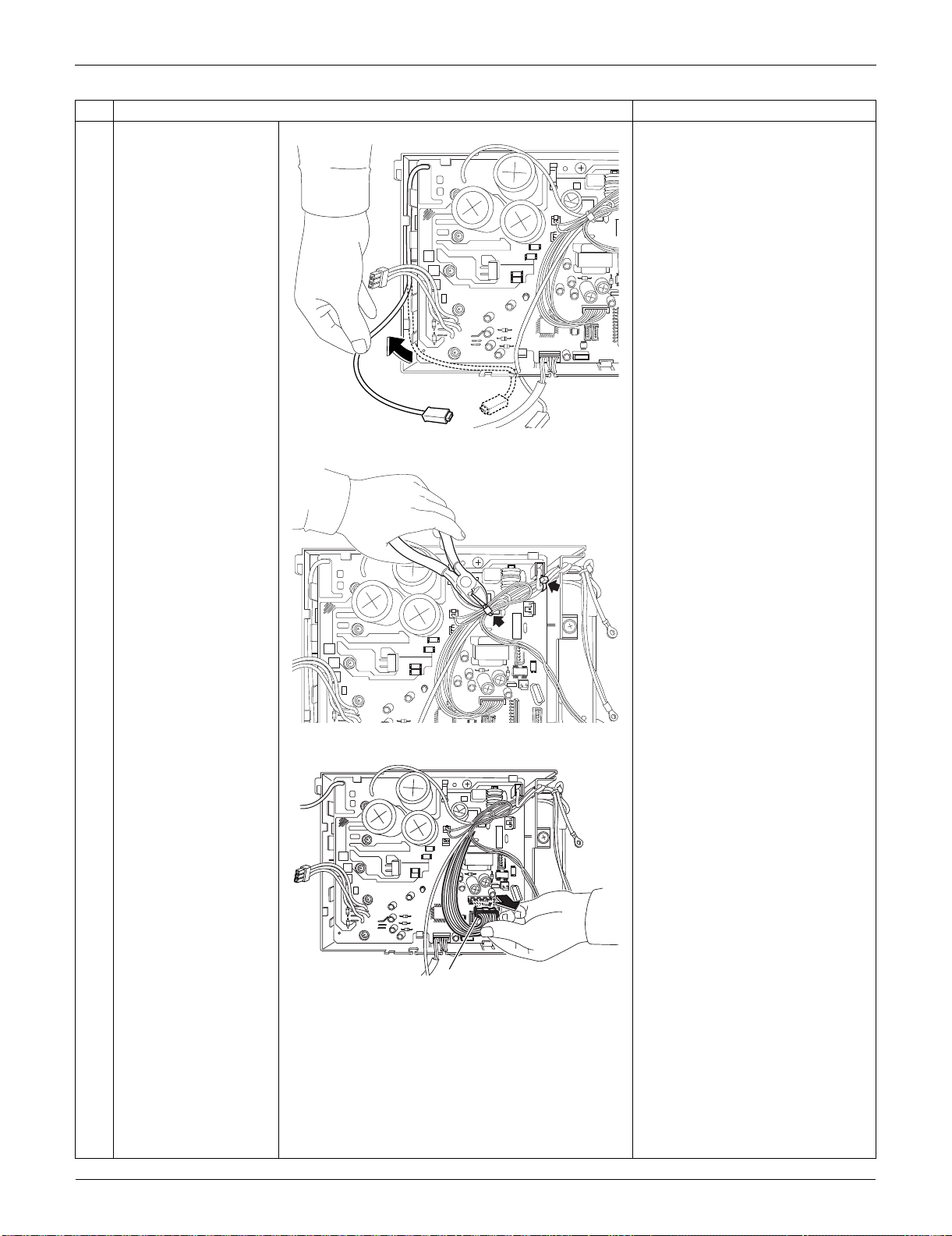
Outdoor Unit: RXS09/12LVJU SiUS091133
275 Removal Procedure
6
Release the harness.
7
Cut the clamps at the 2
locations.
8
Disconnect the
connector for the filter
PCB [S10].
Step
Procedure Points
(R16934)
(R16935)
[S10]
(R16936)
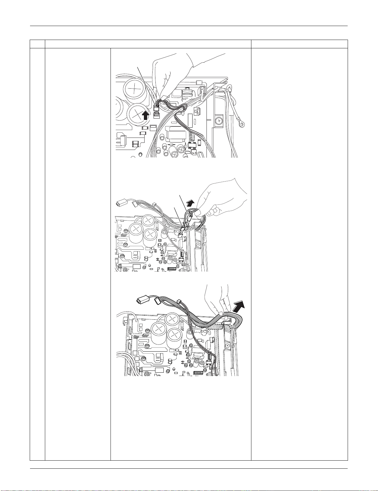
SiUS091133 Outdoor Unit: RXS09/12LVJU
Removal Procedure 276
9
Disconnect the
connector for the forced
operation button PCB
[S100].
10
Disconnect the
connector for the filter
PCB [HL3] [HN3].
11
Release the harnesses
from the hook.
Step
Procedure Points
[S100]
(R16937)
[HL3]
[HN3]
(R16938)
(R16939)
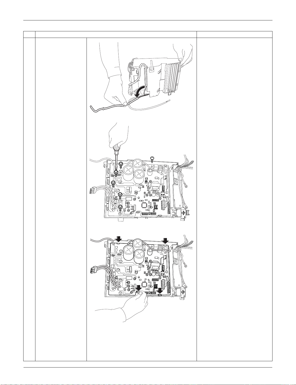
Outdoor Unit: RXS09/12LVJU SiUS091133
277 Removal Procedure
12
Release the harness for
the outdoor
temperature thermistor.
13
Remove the 6 screws.
14
Unfasten the 4 hooks
and remove the main
PCB.
Step
Procedure Points
(R11865)
(R16940)
(R16999)
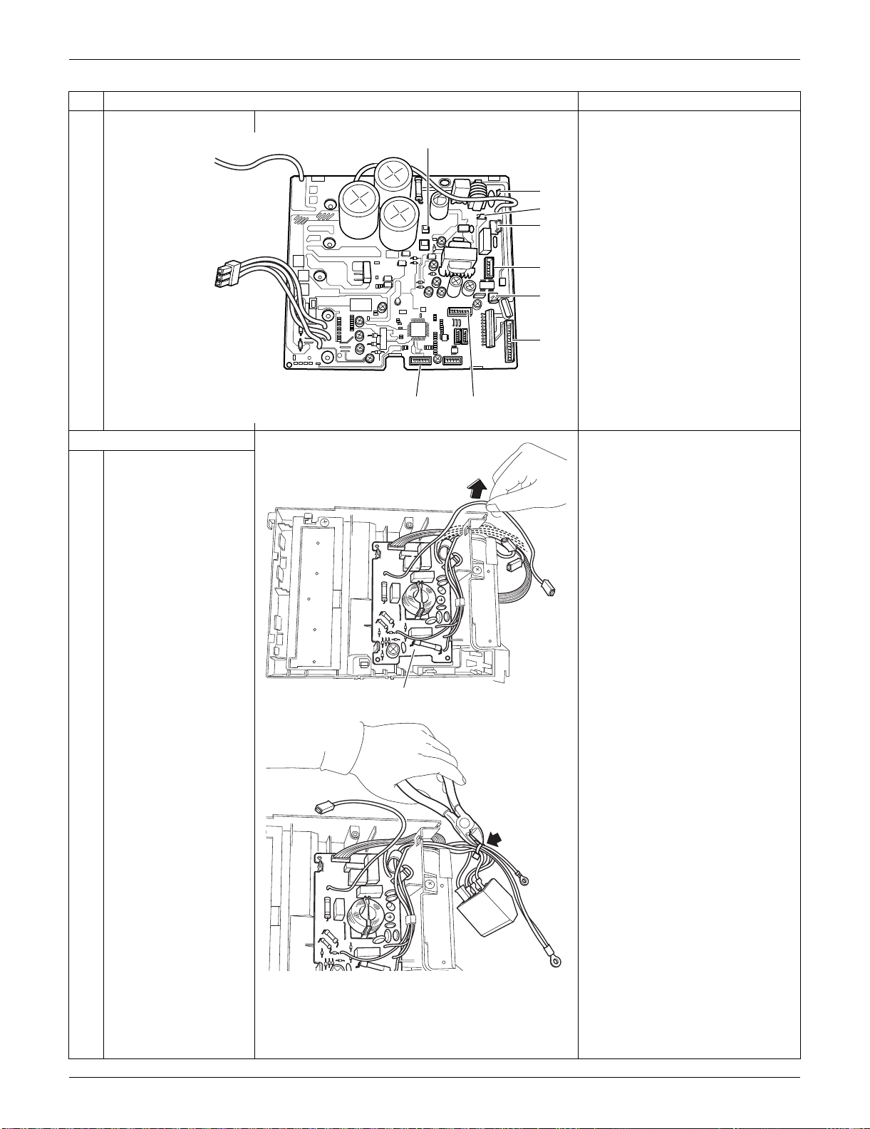
SiUS091133 Outdoor Unit: RXS09/12LVJU
Removal Procedure 278
Refer to page 22 for detail.
[S10] [HL3] [HN3]: filter PCB
[S20]: electronic expansion valve
coil
[S40]: overload protector
[S70]: fan motor
[S80]: four-way valve coil
[S90]: thermistors
[S100]: forced operation button
PCB
2. Remove the filter PCB.
1
Release the harnesses
from the hook.
2
Cut the clamp.
Step
Procedure Points
[S100]
[S90] [S10]
[HN3]
[HL3]
[S80]
[S20]
[S40]
[S70]
(R11868)
Filter PCB
(R17000)
(R16943)
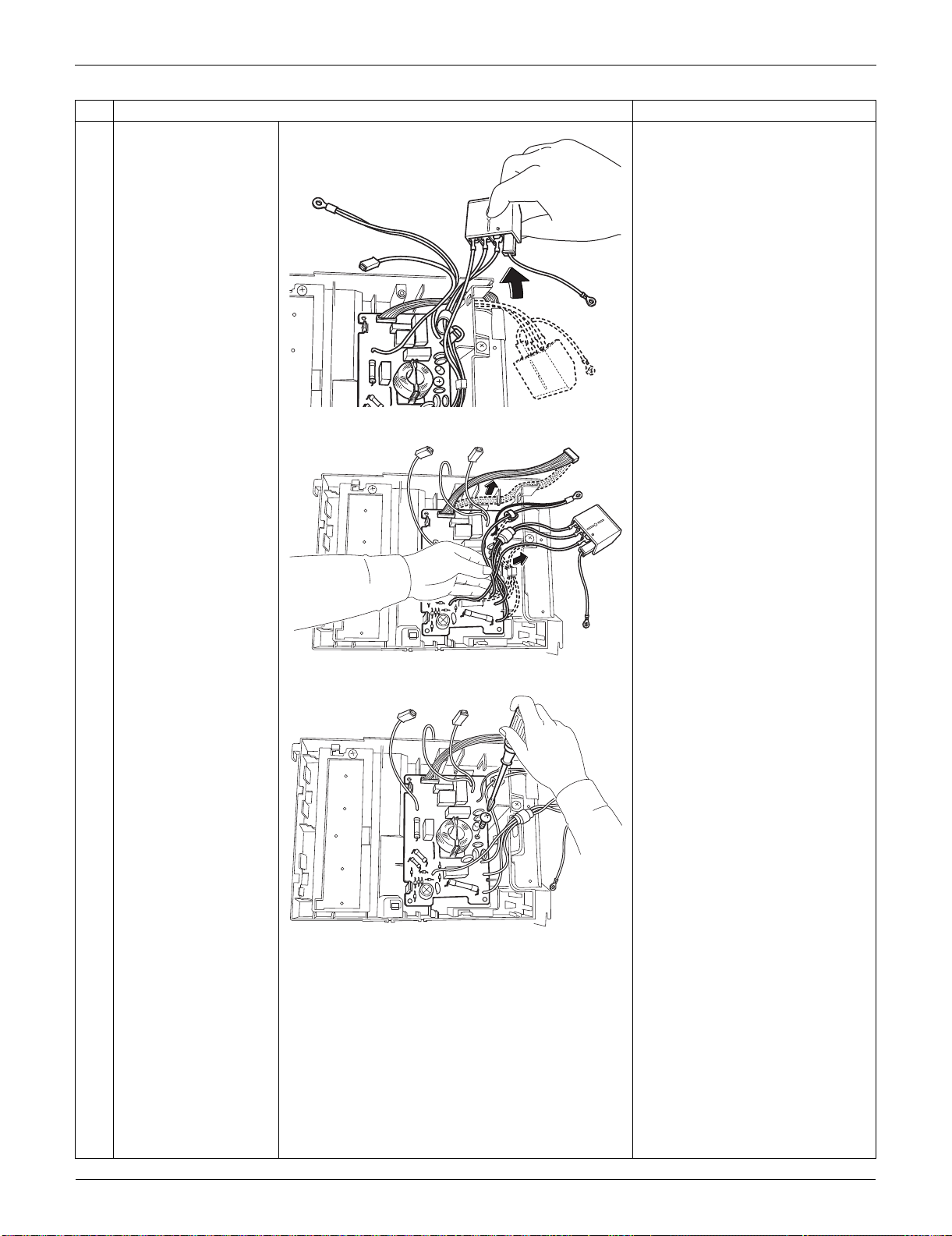
Outdoor Unit: RXS09/12LVJU SiUS091133
279 Removal Procedure
3
Release the harnesses
from the hook.
4
Release the harnesses
from the 2 hooks.
5
Remove the screw.
Step
Procedure Points
(R16944)
(R17001)
(R17002)
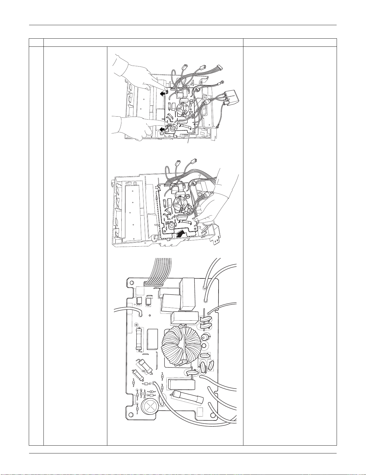
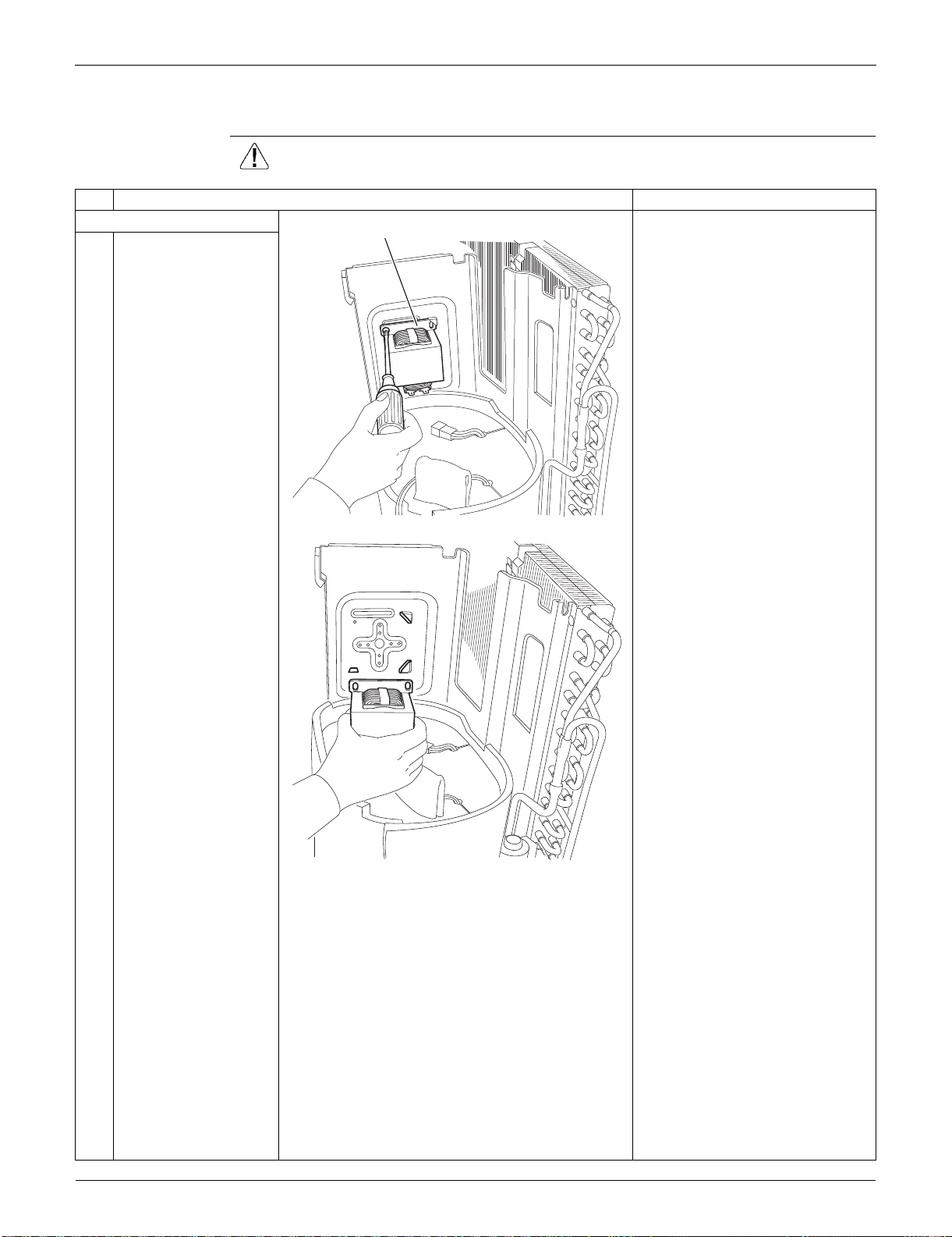
Outdoor Unit: RXS09/12LVJU SiUS091133
281 Removal Procedure
4.4 Removal of Reactor / Partition Plate
Procedure Warning Be sure to wait for 10 minutes or more after turning off all power supplies
before disassembling work.
Step
Procedure Points
1. Remove the reactor. Preparation
Remove the outer panels
according to the “Removal of
Outer Panels / Fan Motor”.
Remove the electrical box
according to the “Removal of
Electrical Box”.
1
Remove the screw and
remove the reactor.
Reactor
(R11879)
(R11880)
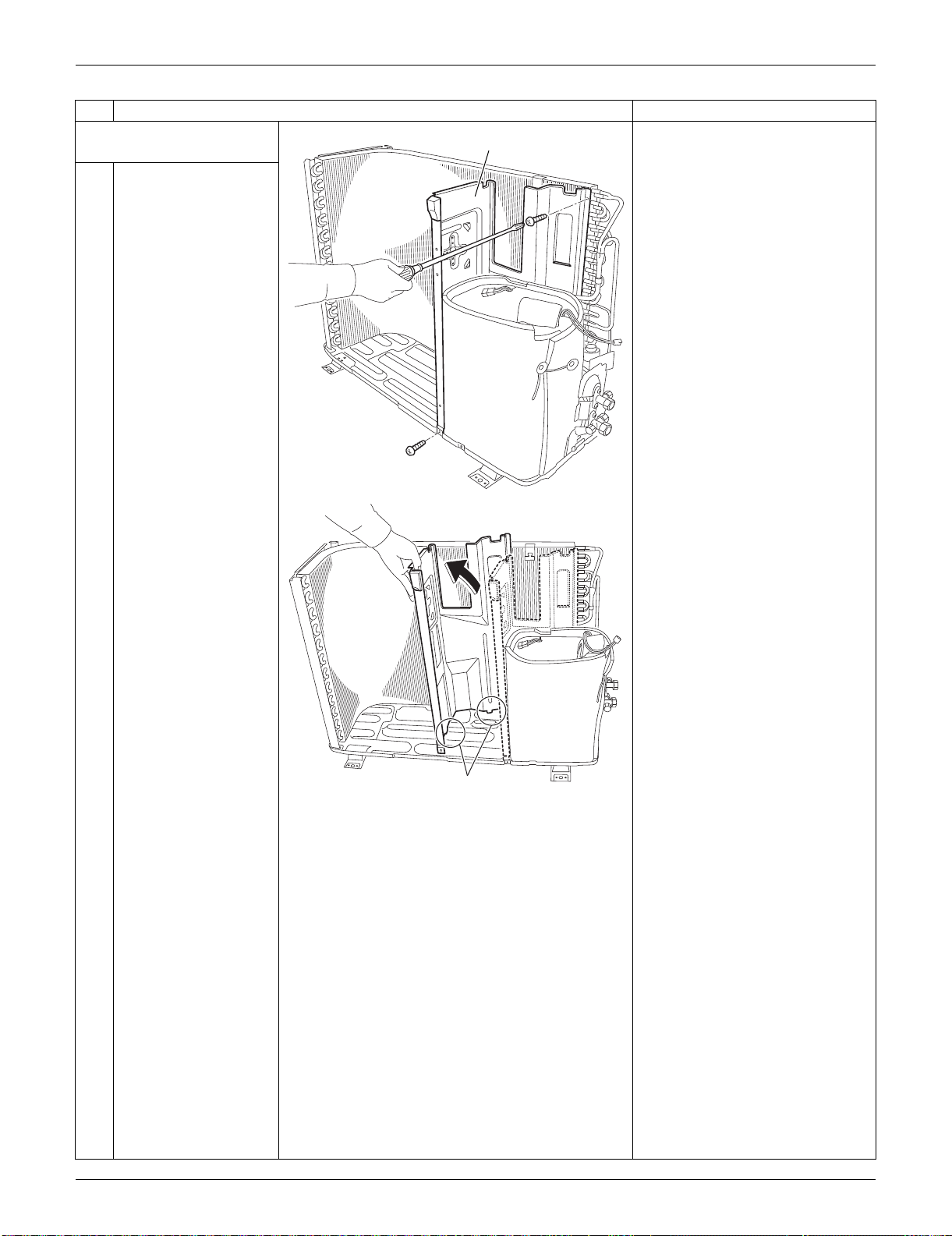
SiUS091133 Outdoor Unit: RXS09/12LVJU
Removal Procedure 282
2. Remove the partition
plate.
1
Remove the 2 screws.
2
The partition plate has
2 hooks on the lower
side. Lift and pull the
partition plate to
remove.
When reassembling, fit the
lower hooks into the bottom
frame.
Step
Procedure Points
Partition plate
(R12273)
Hook
(R13508)
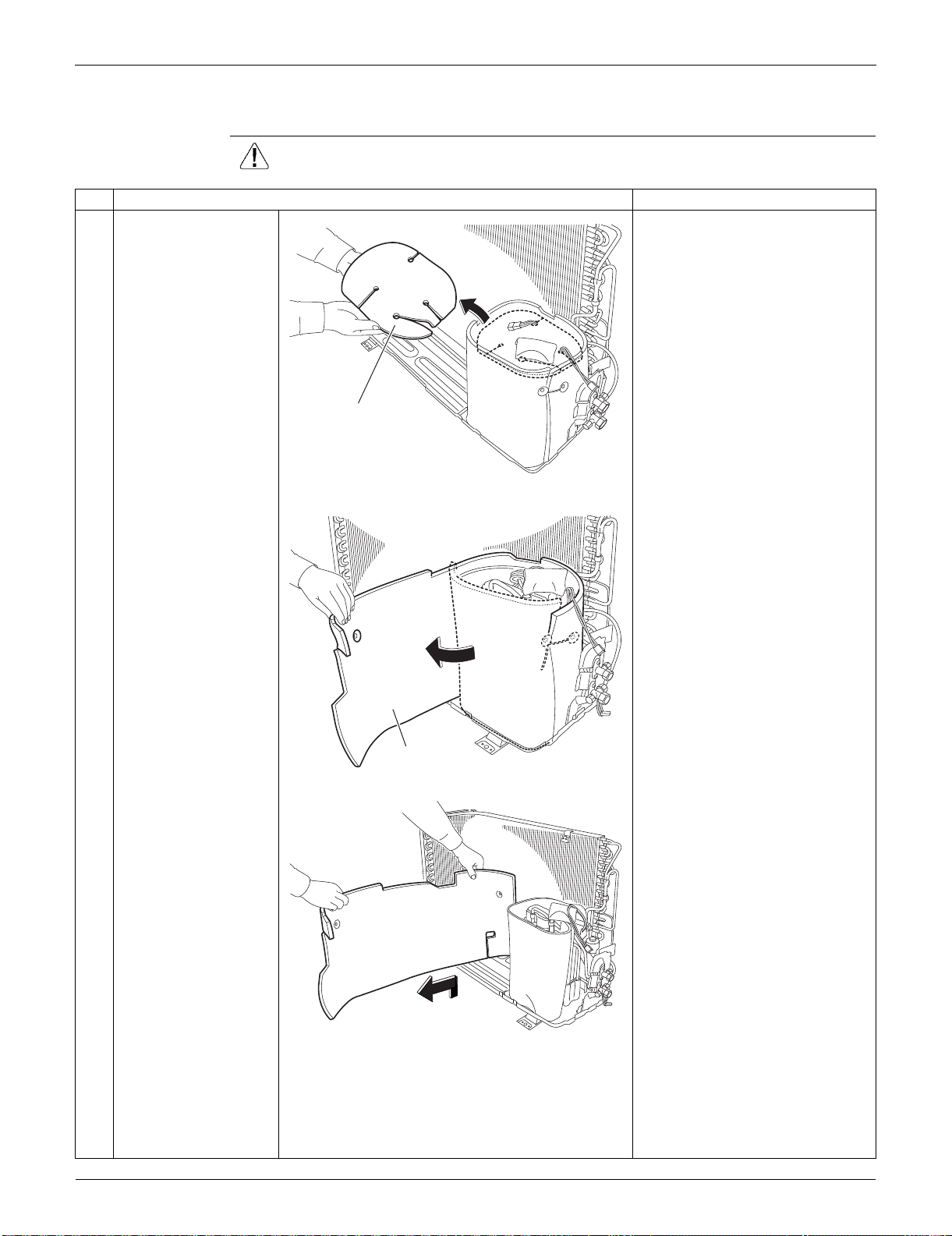
Outdoor Unit: RXS09/12LVJU SiUS091133
283 Removal Procedure
4.5 Removal of Sound Blankets
Procedure Warning Be sure to wait for 10 minutes or more after turning off all power supplies
before disassembling work.
Step
Procedure Points
1
Remove the sound
blanket (top).
Since the piping ports are torn
easily, remove the sound
blankets carefully.
2
Untie the string and
open the sound blanket
(outer).
3
Lift and remove the
sound blanket (outer).
Sound blanket
(top)
(R11884)
Sound blanket
(outer)
(R11885)
(R11886)
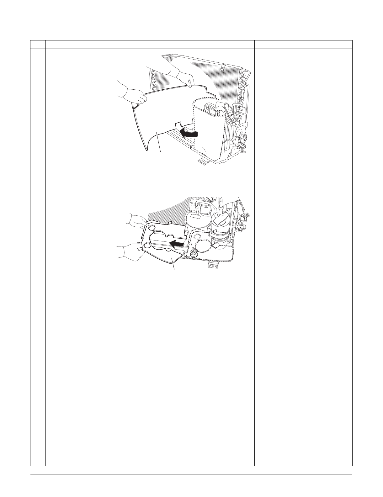
SiUS091133 Outdoor Unit: RXS09/12LVJU
Removal Procedure 284
4
Pull out the sound
blanket (inner).
5
Pull out the sound
blanket (bottom).
Step
Procedure Points
Sound blanket
(inner)
(R11887)
Sound blanket
(bottom)
(R11888)
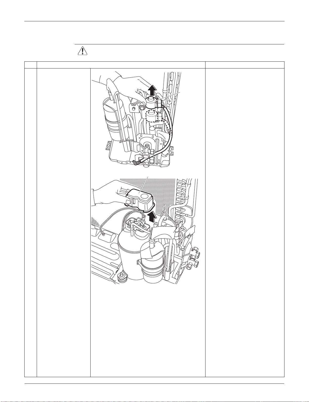
Outdoor Unit: RXS09/12LVJU SiUS091133
285 Removal Procedure
4.6 Removal of Four-Way Valve
Procedure Warning Be sure to wait for 10 minutes or more after turning off all power supplies
before disassembling work.
Step
Procedure Points
1
Pull out the electronic
expansion valve coil.
2
Remove the terminal
cover.
Electronic
expansion
valve coil
(R7233)
Terminal cover
(R7234)

SiUS091133 Outdoor Unit: RXS09/12LVJU
Removal Procedure 286
3
Disconnect the lead
wires of the
compressor.
4
Remove the screw and
remove the four-way
valve coil.
Warning
Be careful not to get yourself
burnt with the pipes and other
parts that are heated by the gas
brazing machine.
Warning
If the refrigerant gas leaks during
work, ventilate the room. (If the
refrigerant gas is exposed to
flames, toxic gas may be
generated.)
Caution
From the viewpoint of global
environment protection, do not
discharge the refrigerant gas in
the atmosphere. Make sure to
collect all the refrigerant gas.
Cautions for restoration
1. Restore the piping by non-
oxidation brazing.
2. It is required to prevent the
carbonization of the oil inside
the four-way valve and the
deterioration of the gaskets
affected by heat. (Keep below
120°C (248°F).) For the sake of
this, wrap the four-way valve
with wet cloth and provide water
so that the cloth does not dry.
5
Remove the sheets of
putty.
Step
Procedure Points
V
W
U
Red (U)
Yellow (V) Blue (W)
(R7235)
Four way valve coil
(R7247)
(R7248)
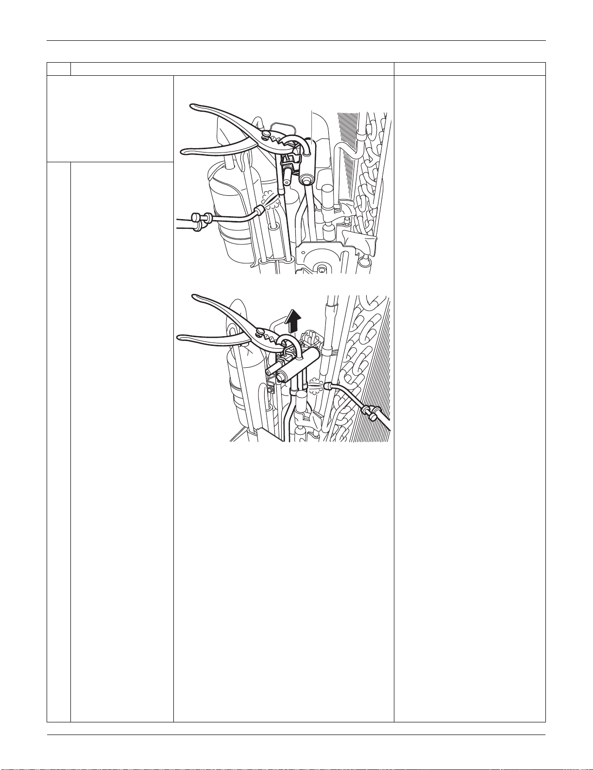
Outdoor Unit: RXS09/12LVJU SiUS091133
287 Removal Procedure
Before working, make
sure that the refrigerant
gas is empty in the circuit.
Be sure to apply nitrogen
replacement when
heating up the brazed
part.
In case of difficulty with gas
brazing machine
1. Disconnect the brazed part
where is easy to disconnect and
restore.
2. Cut pipes on the main unit with
a tube cutter in order to make it
easy to disconnect.
6
Heat up the brazed part
and withdraw the piping
with pliers.
Note:
Never use a metal saw to cut
pipes because the sawdust may
enter the circuit.
When withdrawing the pipes, be
careful not to pinch them firmly
with pliers. The pipes may get
deformed.
Provide a protective sheet or a
steel plate so that the brazing
flame cannot influence
peripheries.
Step
Procedure Points
Four way valve
(R7249)
(R7250)
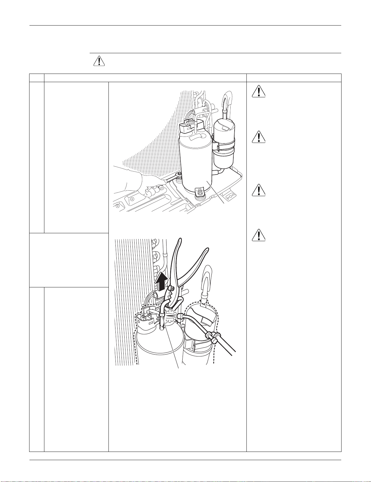
SiUS091133 Outdoor Unit: RXS09/12LVJU
Removal Procedure 288
4.7 Removal of Compressor
Procedure Warning Be sure to wait for 10 minutes or more after turning off all power supplies
before disassembling work.
Step
Procedure Points
1
Remove the 2 nuts of
the compressor. Warning
Be careful not to get yourself
burnt with pipes and other parts
that are heated by the gas
brazing machine.
Warning
If the refrigerant gas leaks during
work, ventilate the room. (If the
refrigerant gas is exposed to
flames, toxic gas may be
generated.)
Warning
Since it may happen that the
refrigerant oil in the compressor
catches fire, prepare wet cloth so
as to extinguish fire immediately.
Caution
From the viewpoint of global
environment protection, do not
discharge the refrigerant gas in
the atmosphere. Make sure to
collect all the refrigerant gas.
Cautions for restoration
1. Restore the piping by non-
oxidation brazing.
2. It is required to prevent the
carbonization of the oil inside
the four-way valve and the
deterioration of the gaskets
affected by heat. (Keep below
120°C (248°F).) For the sake of
this, wrap the four-way valve
with wet cloth and provide water
so that the cloth does not dry.
In case of difficulty with gas
brazing machine
1. Disconnect the brazed part
where is easy to disconnect and
restore.
2. Cut pipes on the main unit with
a tube cutter in order to make it
easy to disconnect.
Before working, make
sure that the refrigerant
gas is empty in the circuit.
Be sure to apply nitrogen
replacement when
heating up the brazed
part.
2
Heat up the brazed part
of the discharge side
and disconnect it.
Compressor
(R11889)
Discharge side
(R12031)
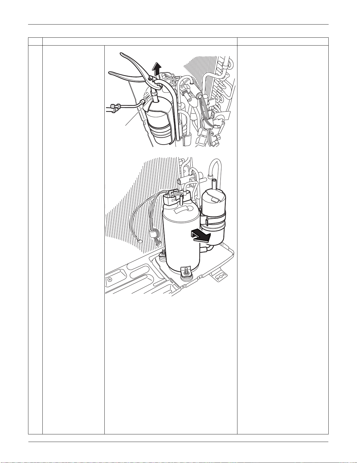
Outdoor Unit: RXS09/12LVJU SiUS091133
289 Removal Procedure
3
Heat up the brazed part
of the suction side and
disconnect it.
Note:
Never use a metal saw to cut
pipes because the sawdust may
enter the circuit.
When withdrawing the pipes, be
careful not to pinch them firmly
with pliers. The pipes may get
deformed.
Provide a protective sheet or a
steel plate so that the brazing
flame cannot influence
peripheries.
Be careful so as not to burn the
compressor terminals, the name
plate, the heat exchanger fins.
4
Lift the compressor up
and remove it.
Step
Procedure Points
Suction side
(R12032)
(R7254)
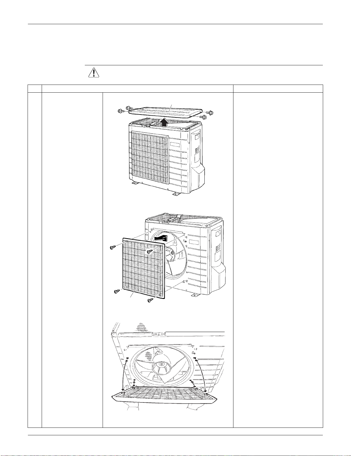
SiUS091133 Outdoor Unit: RXS15/18LVJU
Removal Procedure 290
5. Outdoor Unit: RXS15/18LVJU
5.1 Removal of Outer Panels
Procedure Warning Be sure to wait for 10 minutes or more after turning off all power supplies
before disassembling work.
Step
Procedure Points
1
Remove the 4 screws
and remove the top
panel.
Take care not to cut your finger
by the fins of the outdoor heat
exchanger.
2
Remove the 4 screws
and remove the
discharge grille.
Slide the discharge grille
upward and remove it.
The discharge grille has 4
hooks.
Top panel
(R16754)
Discharge grille
(R16755)
(R16756)
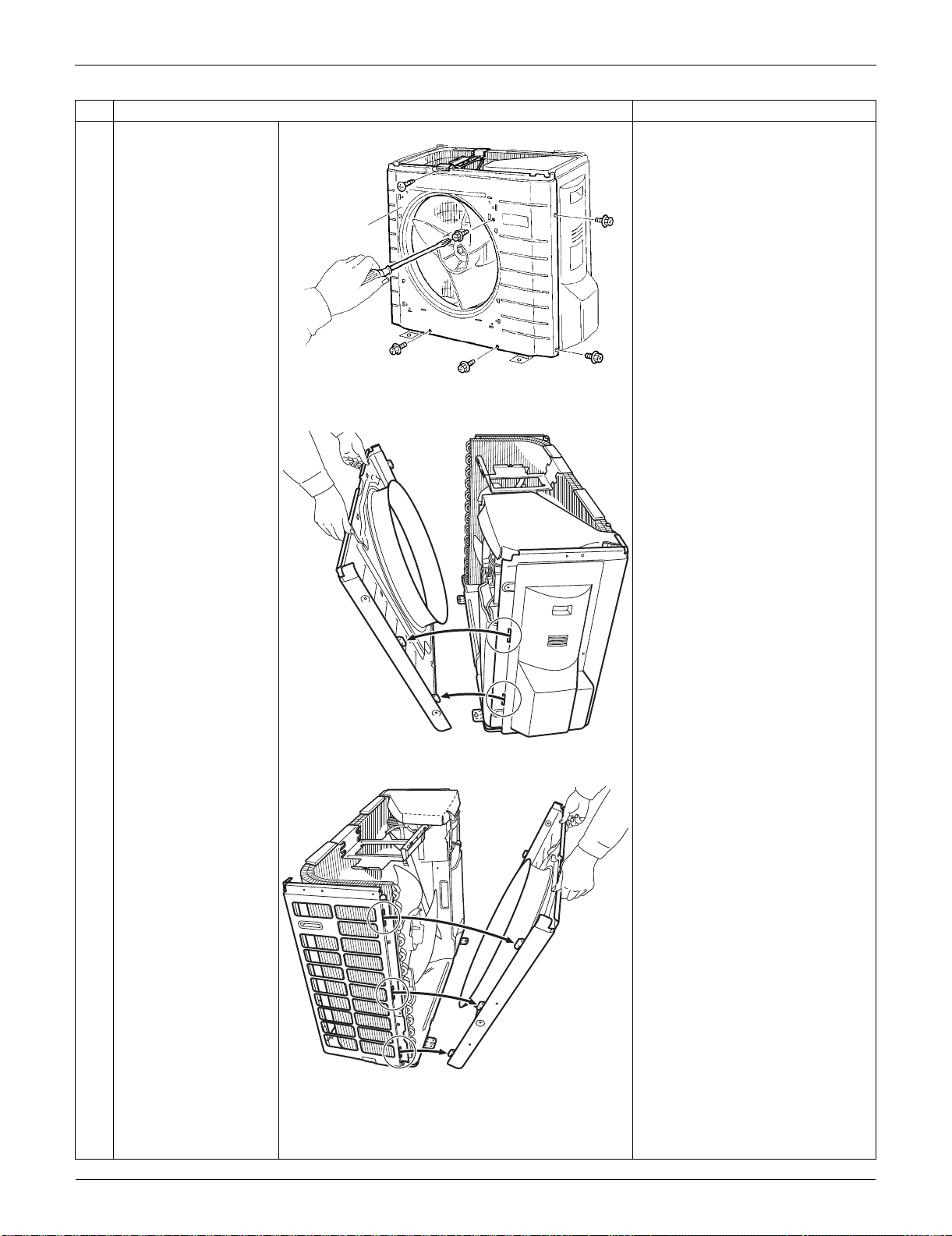
Outdoor Unit: RXS15/18LVJU SiUS091133
291 Removal Procedure
3
Remove the 6 screws
of the front panel.
4
Unfasten the right side
hooks.
5
Unfasten the left side
hooks.
Remove the front
panel.
When reassembling, fit the left
side of the front panel first.
Step
Procedure Points
Front panel
(R16757)
(R16759)
(R16760)
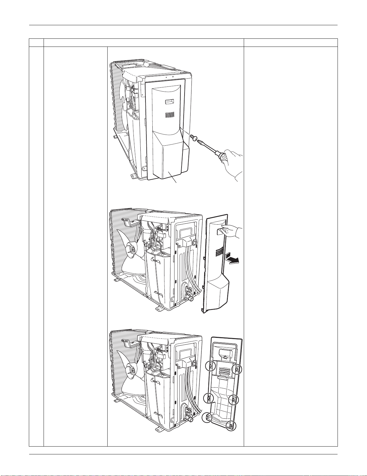
SiUS091133 Outdoor Unit: RXS15/18LVJU
Removal Procedure 292
6
Remove the screw of
the stop valve cover.
7
Pull down the stop
valve cover to unfasten
the hooks and remove
it.
The stop valve cover has 6
hooks.
Step
Procedure Points
Stop valve cover
(R16761)
(R16762)
(R16763)
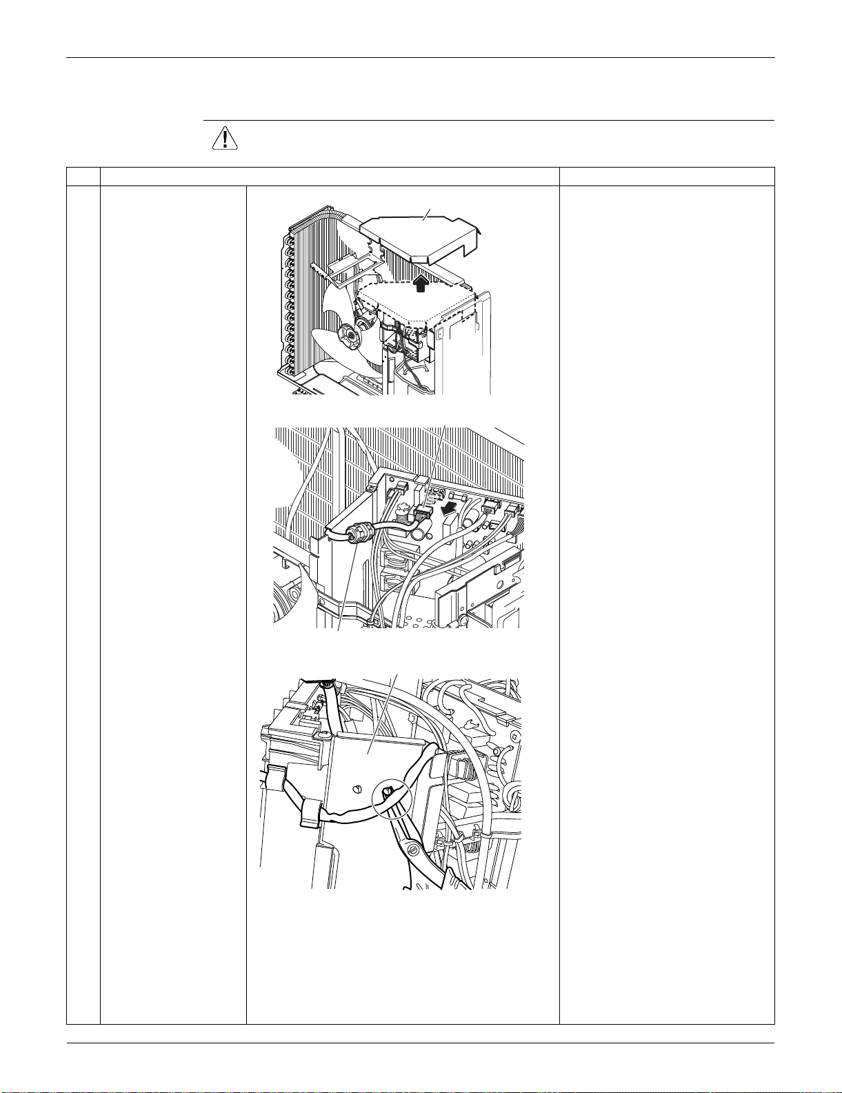
Outdoor Unit: RXS15/18LVJU SiUS091133
293 Removal Procedure
5.2 Removal of Outdoor Fan / Fan Motor
Procedure Warning Be sure to wait for 10 minutes or more after turning off all power supplies
before disassembling work.
Step
Procedure Points
1
Remove the drip proof
cover.
Preparation
Remove the top panel and the
front panel according to the
“Removal of Outer Panels”.
2
Disconnect the
connector for the fan
motor [S70].
3
Release the clamp from
the partition plate.
The ferrite core of the fan motor
lead wire has a clamp.
Drip proof cover
(R17049)
(R16951)
[S70]
Ferrite core
Partition plate
(R16952)
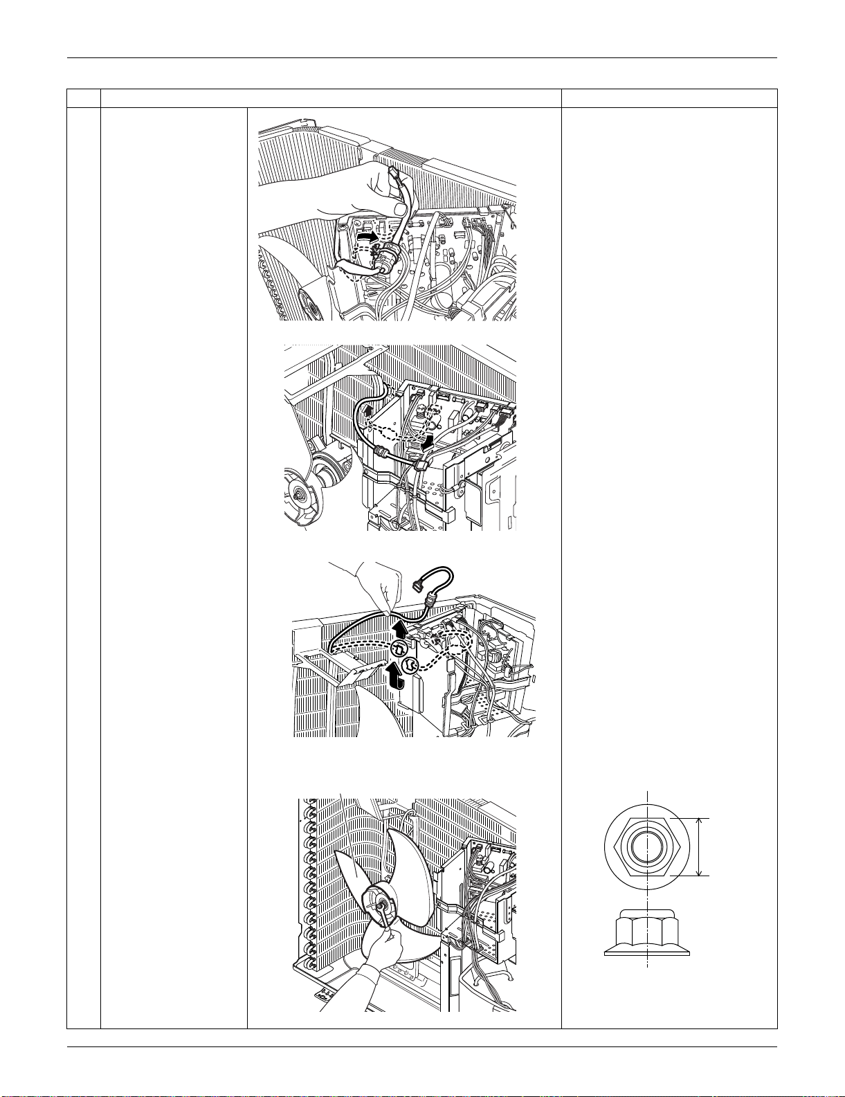
SiUS091133 Outdoor Unit: RXS15/18LVJU
Removal Procedure 294
4
Release the fan motor
lead wire from the
groove and the 2 hooks
of the partition plate.
5
Remove the nut of the
outdoor fan.
Nut size: M6
Step
Procedure Points
(R16764)
(R16796)
(R16797)
Outdoor fan
(R16787)
(R16985)
10 mm
(0.39 inch)

Outdoor Unit: RXS15/18LVJU SiUS091133
295 Removal Procedure
6
Remove the outdoor
fan.
When reassembling, align the
mark of the outdoor fan with
the D-cut section of the motor
shaft.
7
Remove the 2 screws
of the fan motor fixing
frame.
8
Pull up the fan motor
fixing frame to unfasten
the 2 hooks at the
bottom.
9
Remove the fan motor
fixing frame.
Step
Procedure Points
(R16788)
Fan motor fixing frame
(R16953)
(R16790)
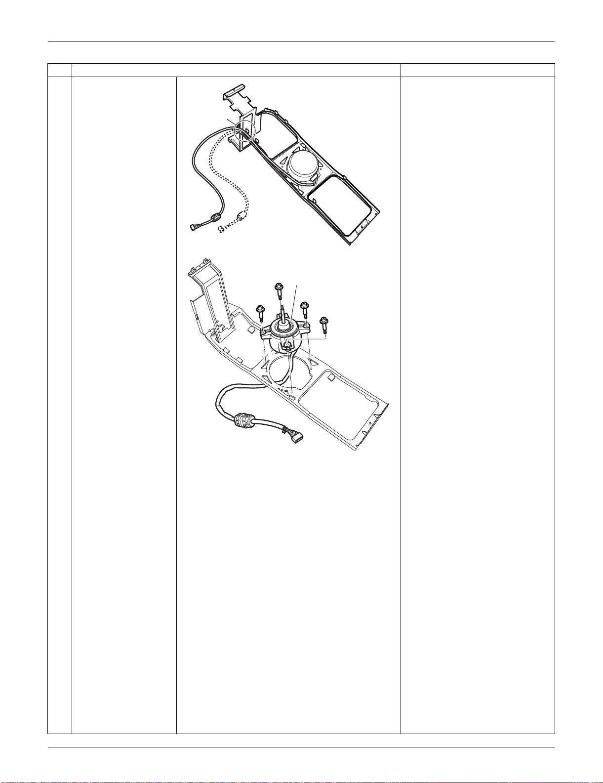
SiUS091133 Outdoor Unit: RXS15/18LVJU
Removal Procedure 296
10
Open the hook and
release the fan motor
lead wire.
11
Remove the 4 screws
and remove the fan
motor.
Step
Procedure Points
(R16954)
Hook
Fan motor
(R16792)
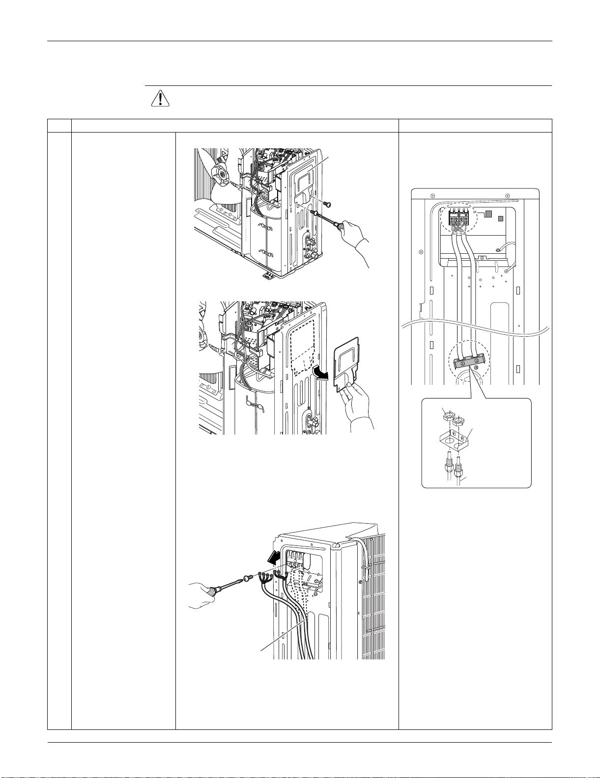
Outdoor Unit: RXS15/18LVJU SiUS091133
297 Removal Procedure
5.3 Removal of Electrical Box
Procedure Warning Be sure to wait for 10 minutes or more after turning off all power supplies
before disassembling work.
Step
Procedure Points
1
Remove the 2 screws
of the protection plate.
When reassembling, pass the
connecting wires through the
conduit and secure them with a
lock nut.
2
Remove the protection
plate.
3
Remove the screws
and remove the
connecting wires and
the power supply wires.
(R16955)
Protection plate
1
2
3
Lock nut
Conduit
mounting plate
Conduit 1/2 inch
(21.3mm)
(R16825)
(R16956)
(R16914)
Power supply wire
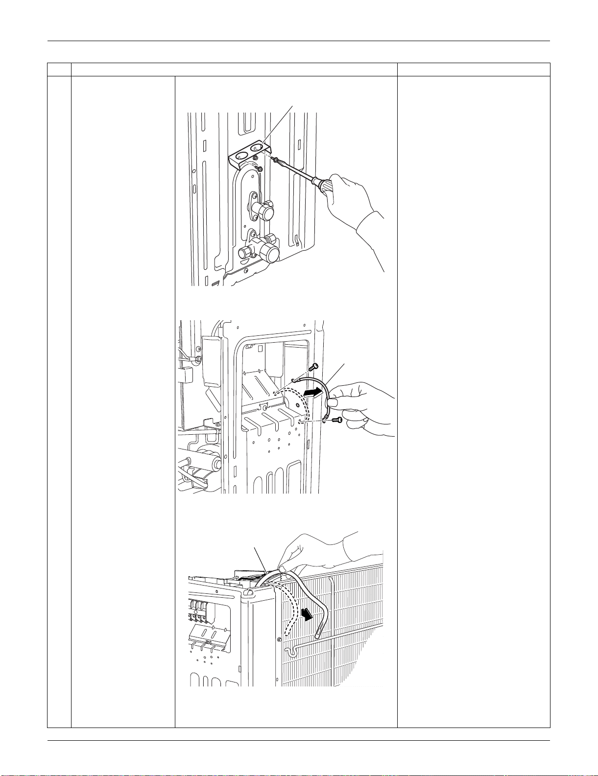
SiUS091133 Outdoor Unit: RXS15/18LVJU
Removal Procedure 298
4
Remove the 2 screws
of the conduit mounting
plate.
5
Remove the conduit
mounting plate.
6
Remove the 2 screws
and remove the ground
wire.
7
Pull out the outdoor
temperature thermistor.
Step
Procedure Points
(R16780)
Conduit mounting plate
(R16781)
Ground wire
(R16794)
Outdoor temperature
thermistor

Outdoor Unit: RXS15/18LVJU SiUS091133
299 Removal Procedure
8
Remove the 4 screws
of the right side panel.
9
Unfasten the hooks and
remove the right side
panel.
When reassembling, insert the
upper hook and the 2 lower
hooks back into place.
10
Cut the clamp.
Step
Procedure Points
Right side panel
(R16957)
Hook
(R16823)
Hook
(R16824)
(R16766)
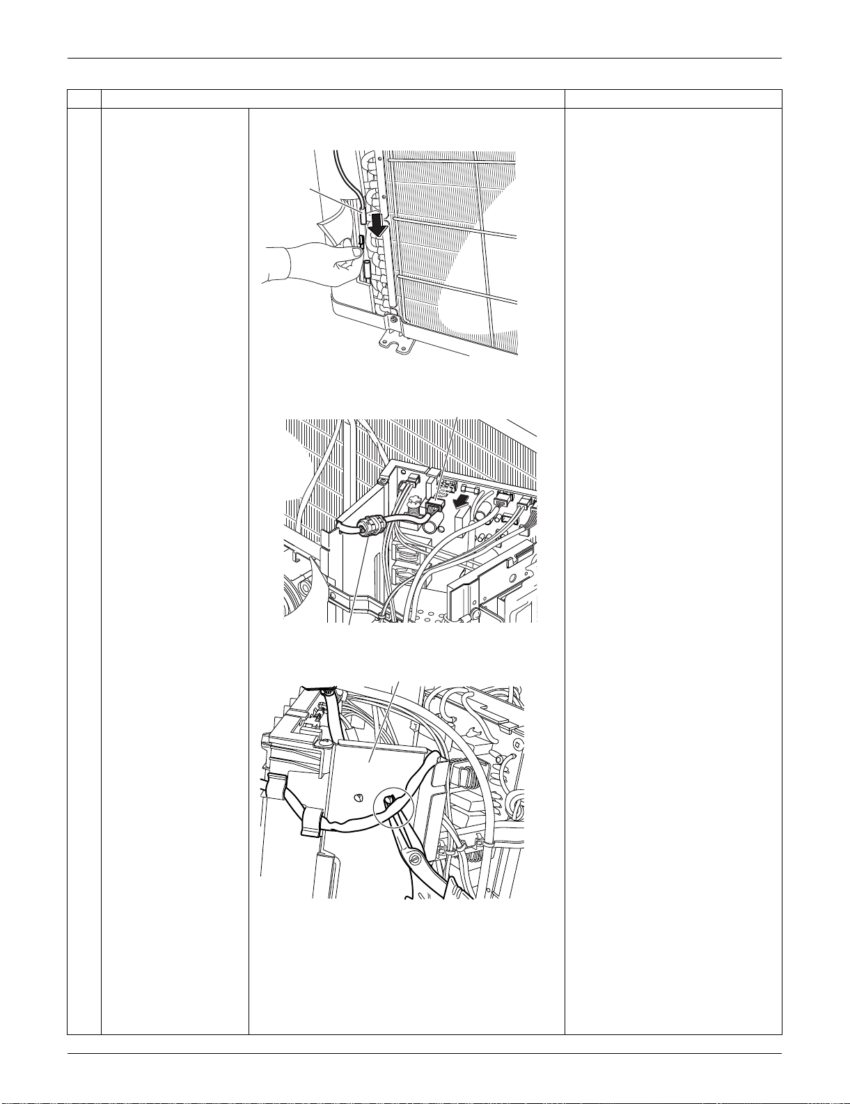
SiUS091133 Outdoor Unit: RXS15/18LVJU
Removal Procedure 300
11
Pull out the outdoor
heat exchanger
thermistor.
12
Disconnect the
connector for the fan
motor [S70].
13
Release the clamp from
the partition plate.
The ferrite core of the fan motor
lead wire has a clamp.
Step
Procedure Points
Outdoor
heat
exchanger
thermistor
(R16819)
(R16951)
[S70]
Ferrite core
Partition plate
(R16952)
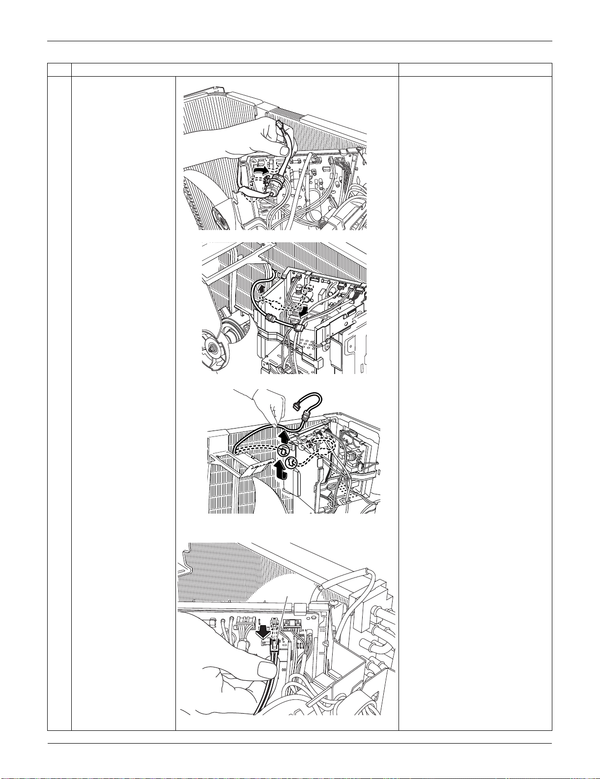
Outdoor Unit: RXS15/18LVJU SiUS091133
301 Removal Procedure
14
Release the fan motor
lead wire from the
groove and the 2 hooks
of the partition plate.
15
Disconnect the
connector for the
overload protector
[S40].
Step
Procedure Points
(R16764)
(R16796)
(R16797)
[S40]
(R16782)
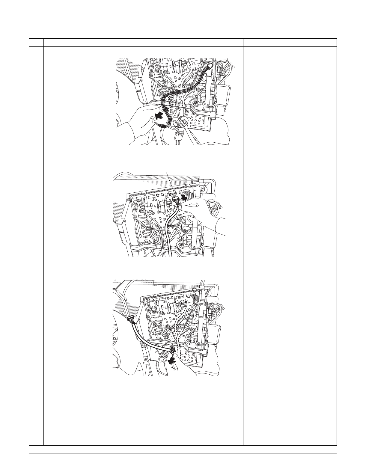
SiUS091133 Outdoor Unit: RXS15/18LVJU
Removal Procedure 302
16
Pull out the clamp.
17
Disconnect the
connector for the
electronic expansion
valve coil [S20].
18
Pull out the clamp (2
locations).
Step
Procedure Points
(R16803)
(R16798)
[S20]
(R16799)
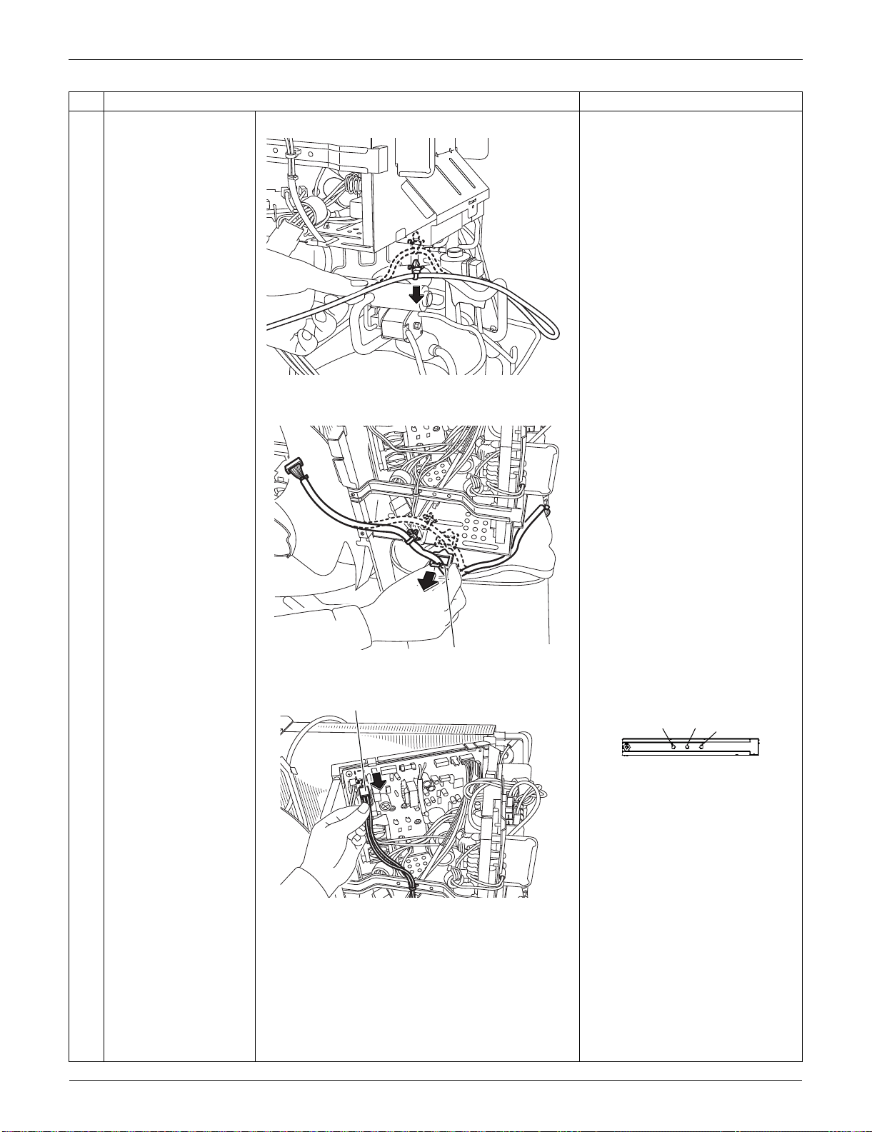
Outdoor Unit: RXS15/18LVJU SiUS091133
303 Removal Procedure
19
Remove the wire
saddle.
20
Disconnect the
connector for the four-
way valve coil [S80].
When reassembling, insert the
clamps of harnesses as below.
When reassembling, connect
the connectors in the following
order.
(1) [S80]
(2) [S20]
(3) [S40]
(4) [S70]
Step
Procedure Points
(R16767)
Wire saddle
(R16800)
(R16801)
[S80]
[S40]
[S80]
[S20]
(R14363)
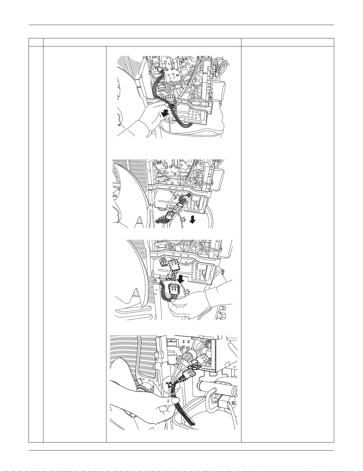
SiUS091133 Outdoor Unit: RXS15/18LVJU
Removal Procedure 304
21
Pull out the clamp.
22
Disconnect the relay
connector for the
compressor.
23
Release the harness of
the relay connector
from the wire saddle.
24
Pull out the clamp from
the partition plate.
Step
Procedure Points
(R16802)
(R14312)
(R14313)
(R16950)
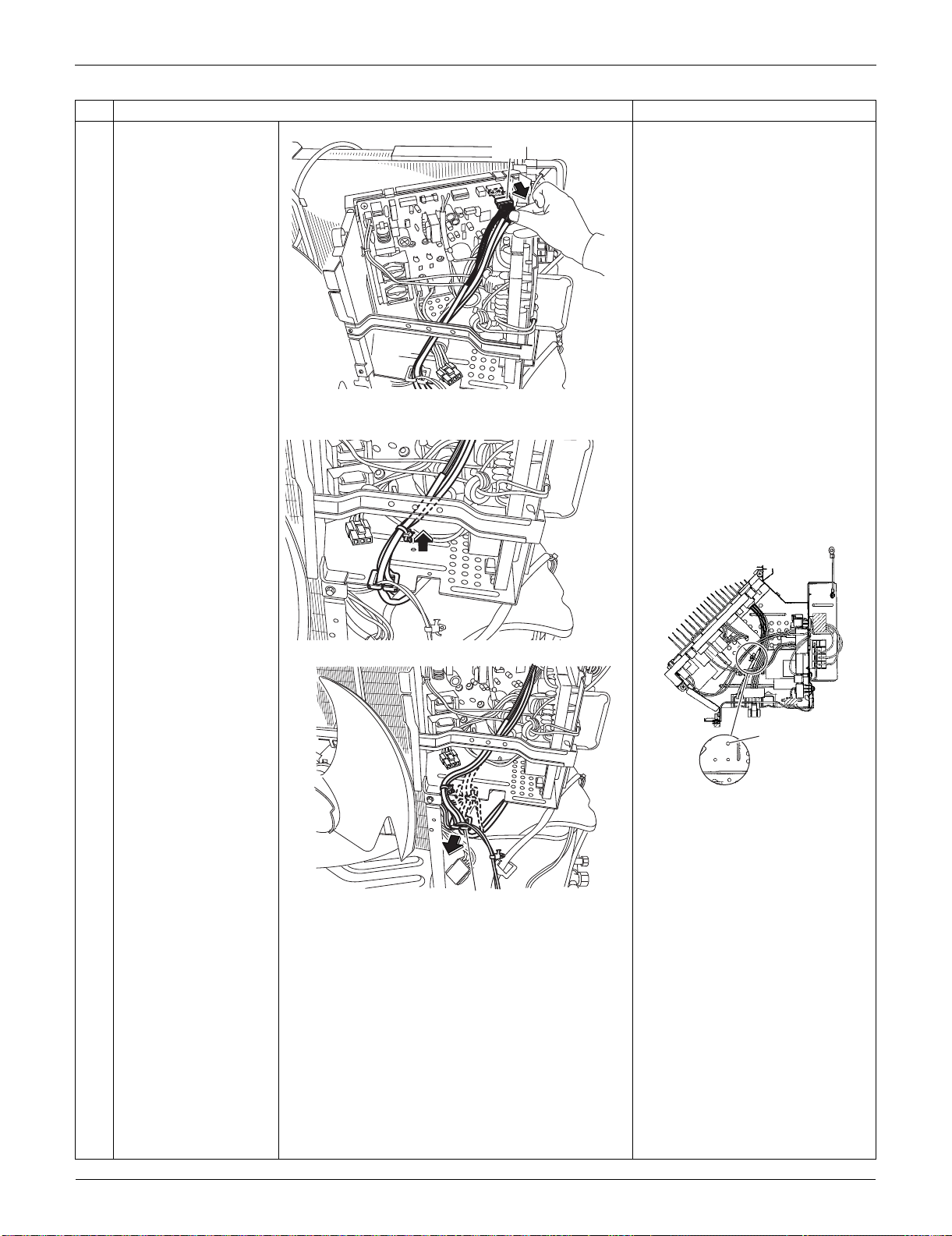
Outdoor Unit: RXS15/18LVJU SiUS091133
305 Removal Procedure
25
Disconnect the
connector for the
thermistors [S90].
26
Pull out the clamp. When reassembling, pass the
thermistor harness under the
harnesses (HL2: blue, HN2:
white) from the filter PCB.
When reassembling, insert the
clamp as below.
27
Remove the wire
saddle.
Step
Procedure Points
(R16806)
[S90]
(R14315)
(R16958)
Thermistor
harnesses
(R14316)
Wire saddle
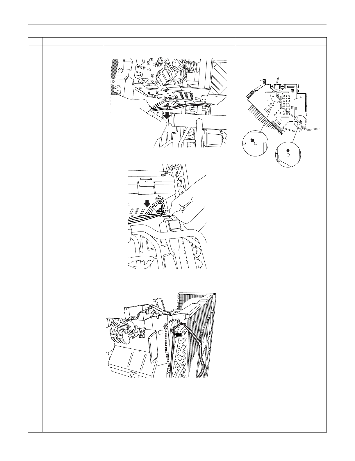
SiUS091133 Outdoor Unit: RXS15/18LVJU
Removal Procedure 306
28
Pull out the clamp (3
locations).
When reassembling, insert the 2
clamps into the bottom of the
electrical box.
Step
Procedure Points
(R16768)
(R16769)
(R16770)
(R16749)
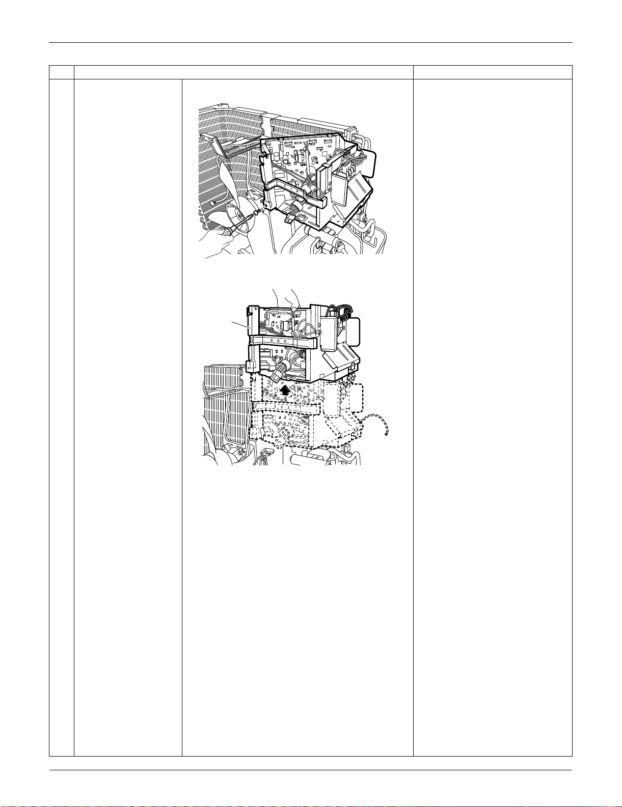
Outdoor Unit: RXS15/18LVJU SiUS091133
307 Removal Procedure
29
Remove the screw.
30
Remove the electrical
box.
Step
Procedure Points
(R16771)
(R16772)
Electrical box
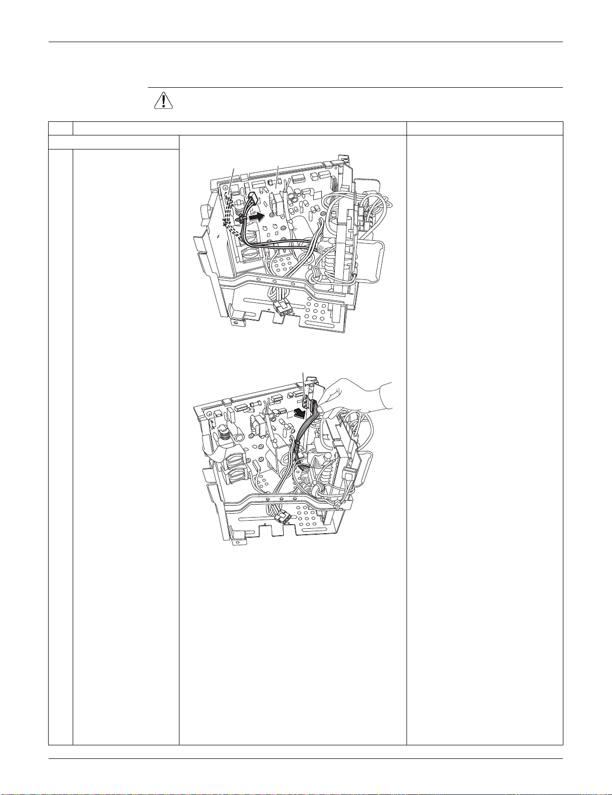
SiUS091133 Outdoor Unit: RXS15/18LVJU
Removal Procedure 308
5.4 Removal of PCBs
Procedure Warning Be sure to wait for 10 minutes or more after turning off all power supplies
before disassembling work.
Step
Procedure Points
1. Remove the main PCB. [S12]: for [HL4] [HN4] on filter PCB
1
Disconnect the
connector [S12] and
pull out the clamp.
2
Disconnect the
connector [S10].
[S10]: for [S11] on filter PCB
(R16959)
[S12]
Main PCB
(R16808)
[S10]
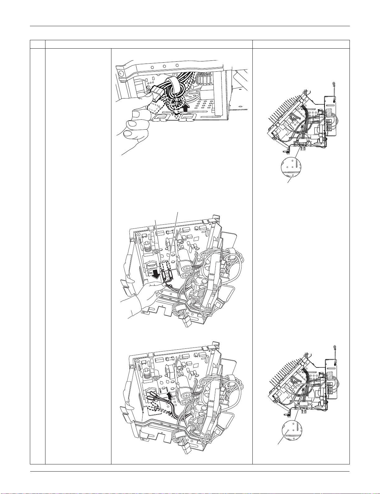
Outdoor Unit: RXS15/18LVJU SiUS091133
309 Removal Procedure
3
Pull out the clamp. The compressor harness has a
clamp.
When reassembling, insert the
clamp as below.
4
Disconnect the
connectors [HN3] and
[HL3].
[HL3]: for [HL2] on filter PCB
[HN3]: for [HN2] on filter PCB
5
Pull out the clamp. When reassembling, insert the
clamp as below.
Step
Procedure Points
(R16775)
(R16747)
Compressor harness
(red, blue, yellow)
[HN3]: white
[HL3]: blue
(R16809)
(R16810)
(R16960)
Harnesses from [HL2]
(blue) and [HN2] (white)
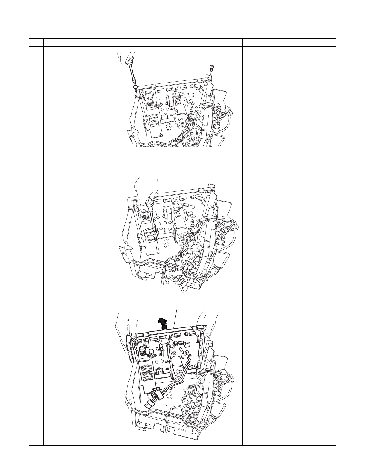
SiUS091133 Outdoor Unit: RXS15/18LVJU
Removal Procedure 310
6
Remove the 2 upper
screws.
7
Remove the lower
screw.
8
Lift the main PCB
ASSY.
Step
Procedure Points
(R16811)
(R16812)
(R16813)
Main PCB ASSY
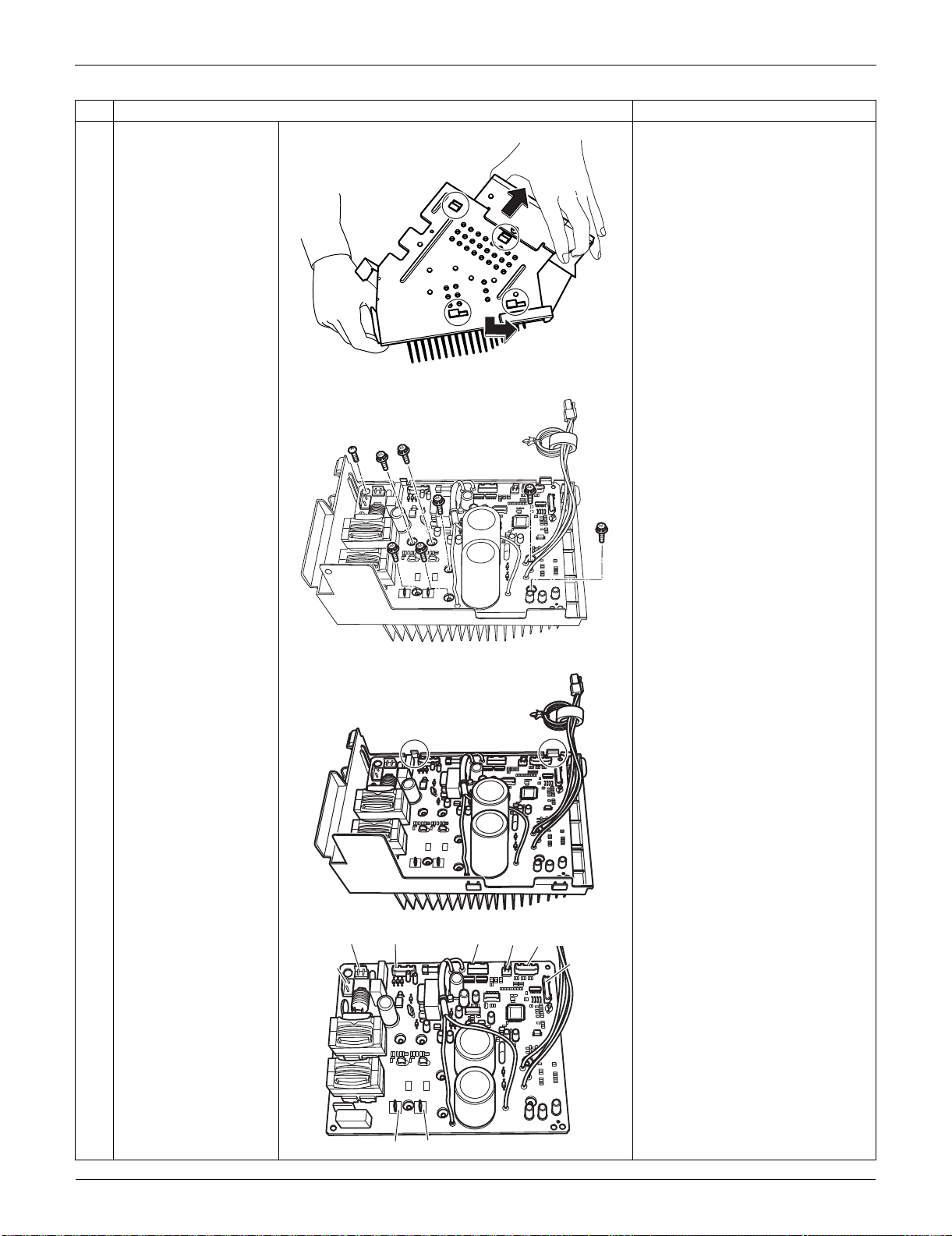
Outdoor Unit: RXS15/18LVJU SiUS091133
311 Removal Procedure
9
Unfasten the 4 hooks at
the bottom.
10
Remove the 8 screws.
11 Unfasten the 2 hooks.
Refer to page 24 for detail.
12 Remove the main PCB. [S10] [S12]: filter PCB
[S20]: electronic expansion valve
coil
[S40]: overload protector
[S70]: fan motor
[S80]: four-way valve coil
[S90]: thermistors
[HL3] [HN3]: filter PCB
Step
Procedure Points
(R16814)
(R14330)
(R14331)
(R14332)
[S80]
[S12]
[HN3][HL3]
[S70] [S20] [S40] [S90]
[S10]
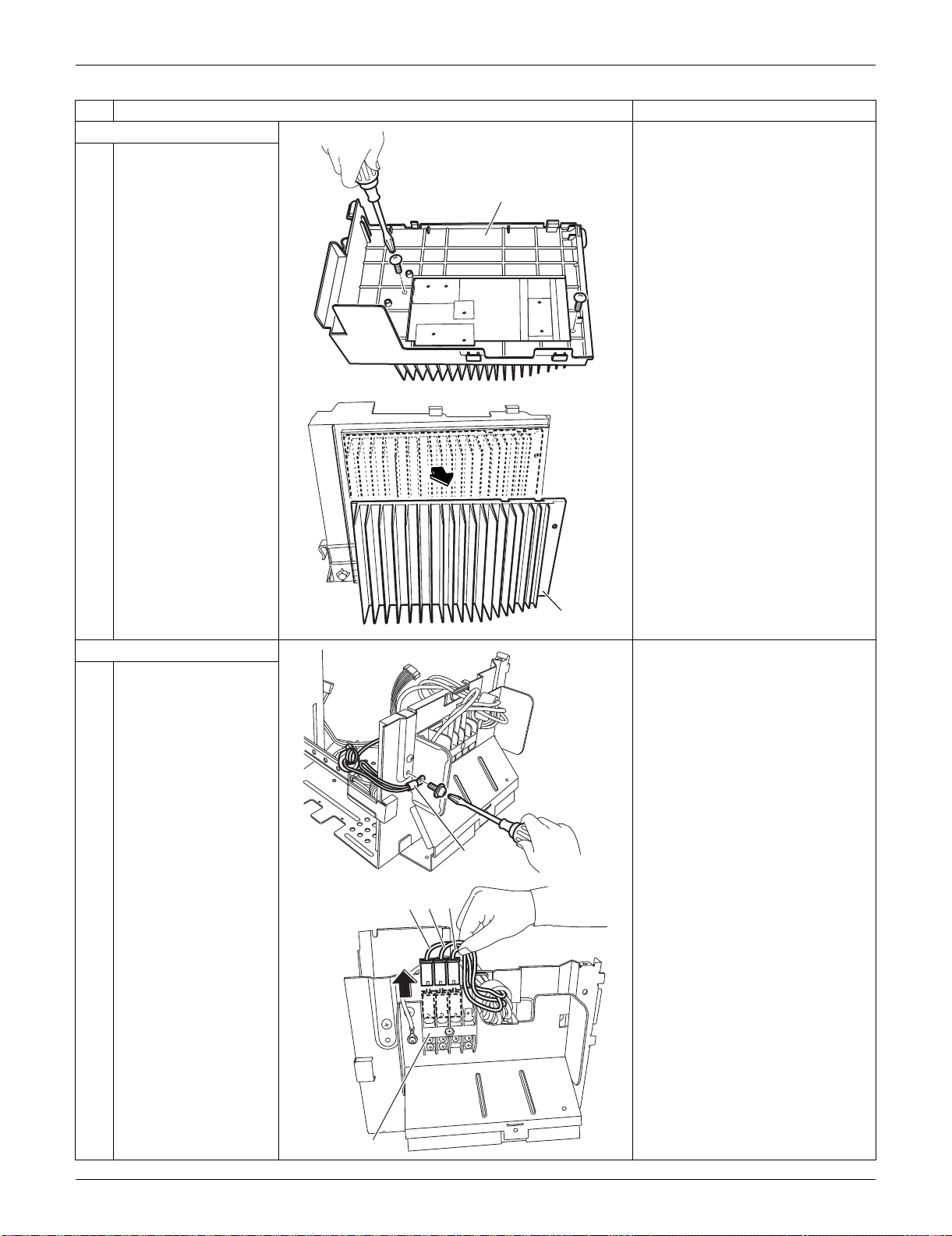
SiUS091133 Outdoor Unit: RXS15/18LVJU
Removal Procedure 312
2. Remove the radiation fin.
1 Remove the 2 screws
on the bottom of the
electrical box.
2 Remove the radiation
fin.
3. Remove the filter PCB.
1 Remove the ground
wire screw.
2 Pull out the terminals
from the terminal board.
(1): black
(2): white
(3): red
Step
Procedure Points
(R14333)
Electrical box
(R14334)
Radiation fin
(R16822)
Ground wire
Terminal board
(R16815)
(1) (2) (3)
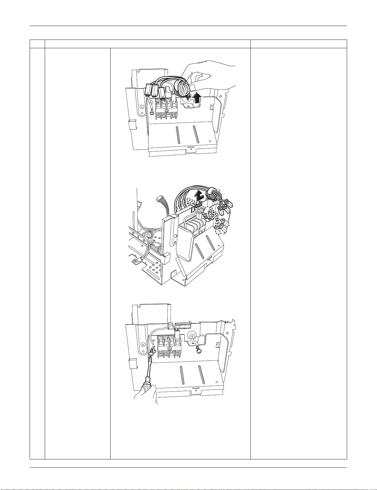
Outdoor Unit: RXS15/18LVJU SiUS091133
313 Removal Procedure
3 Pull out the clamp.
4 Release the harnesses
from the groove.
5 Remove the 2 screws.
Step
Procedure Points
(R16816)
(R16817)
(R16818)
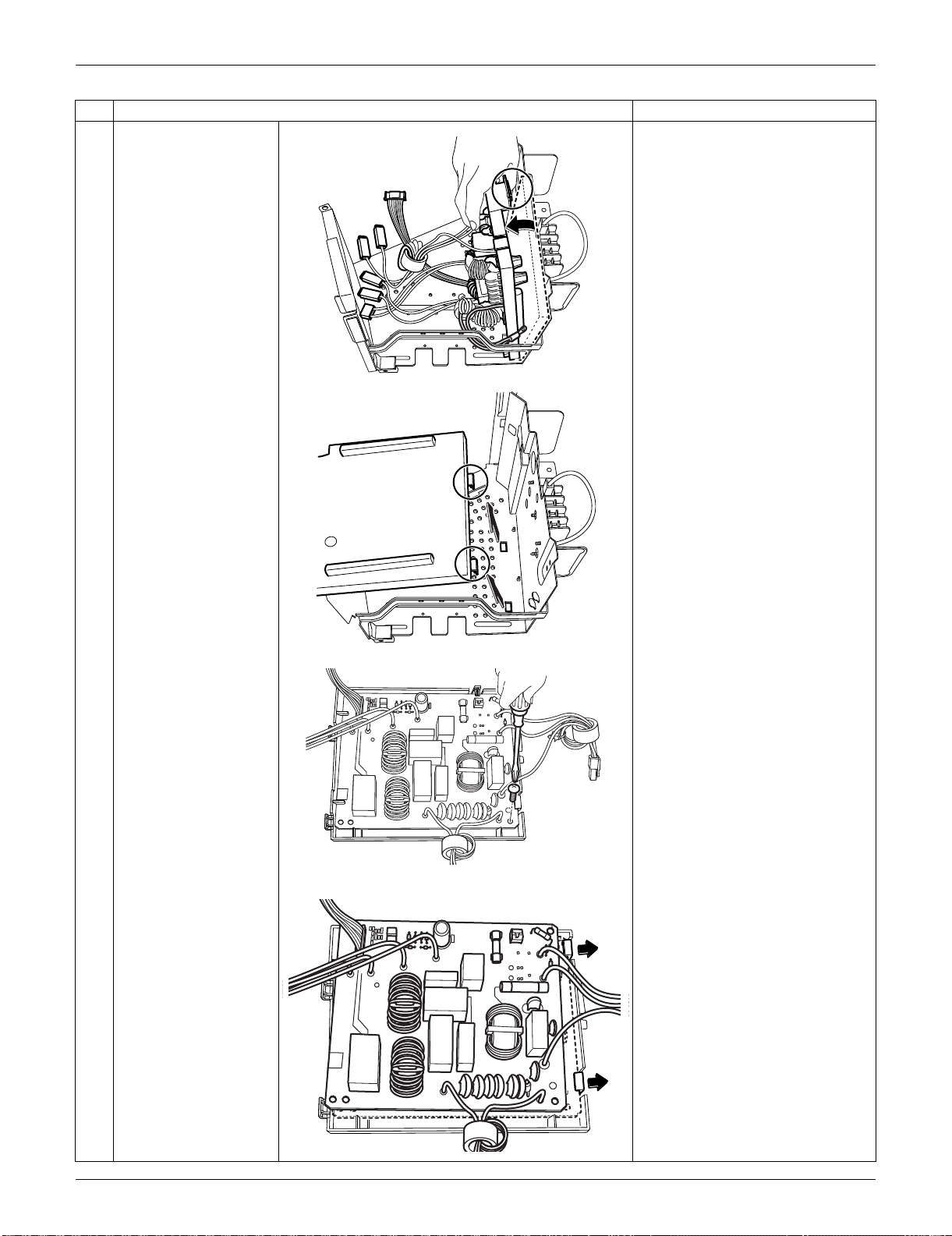
SiUS091133 Outdoor Unit: RXS15/18LVJU
Removal Procedure 314
6 Unfasten the 3 hooks of
the filter PCB ASSY.
7 Remove the screw.
8 Unfasten the 2 hooks.
Step
Procedure Points
(R16961)
(R14367)
(R14368)
(R16964)
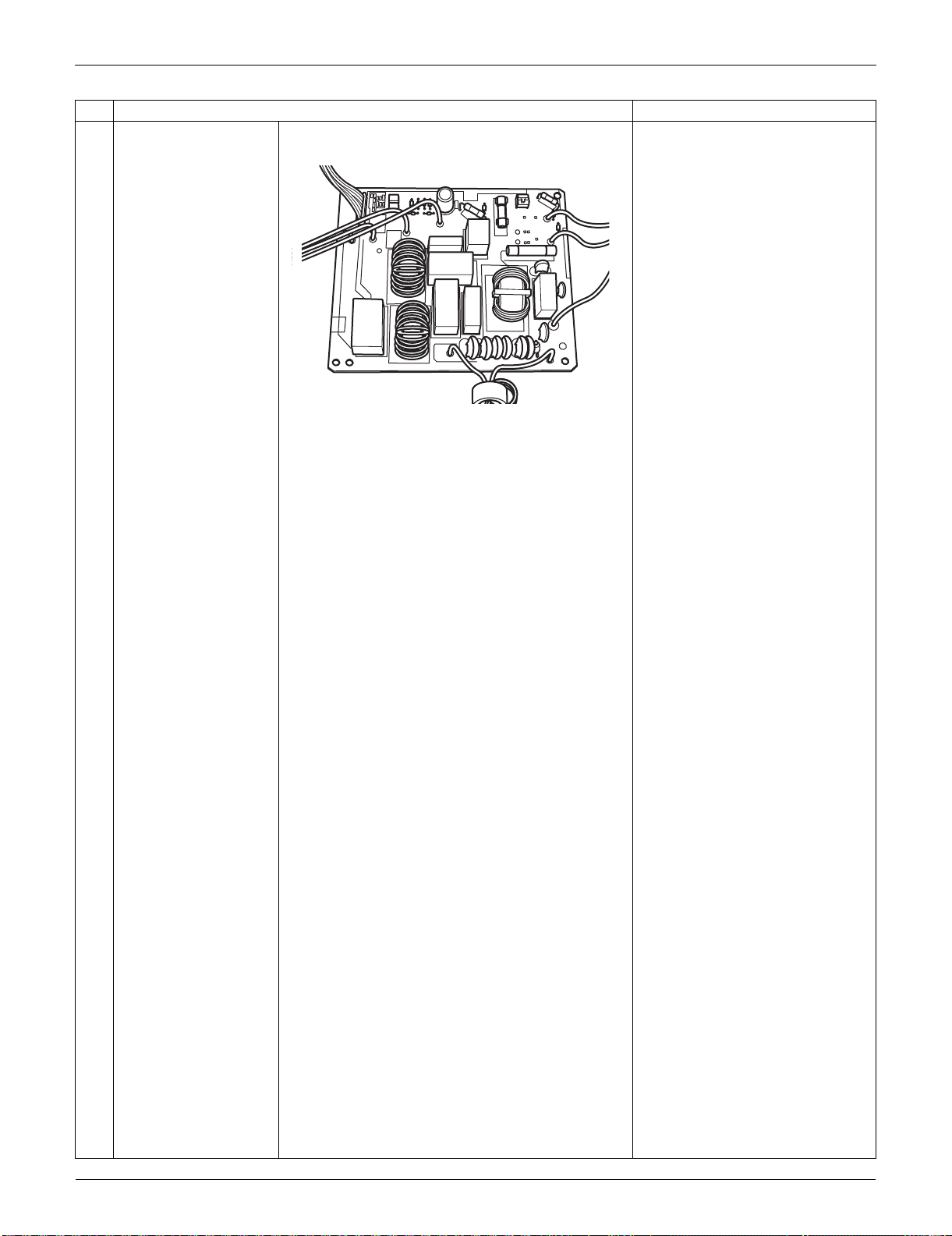
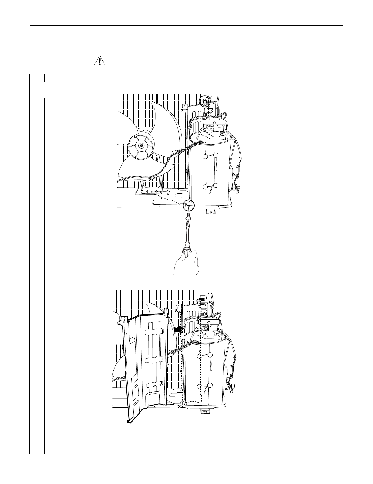
SiUS091133 Outdoor Unit: RXS15/18LVJU
Removal Procedure 316
5.5 Removal of Sound Blankets / Thermistors
Procedure Warning Be sure to wait for 10 minutes or more after turning off all power supplies
before disassembling work.
Step
Procedure Points
1. Remove the partition
plate.
1
Remove the 2 screws.
2
Remove the partition
plate.
(R16773)
(R16774)
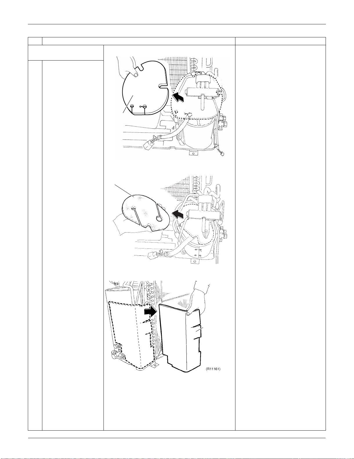
Outdoor Unit: RXS15/18LVJU SiUS091133
317 Removal Procedure
2. Remove the sound
blankets.
1
Remove the sound
blanket (top upper).
2
Remove the sound
blanket (top lower).
3
Remove the sound
blanket (back).
Step
Procedure Points
(R16962)
Sound blanket
(top upper)
Sound blanket
(top lower)
(R16783)
Sound blanket
(back)
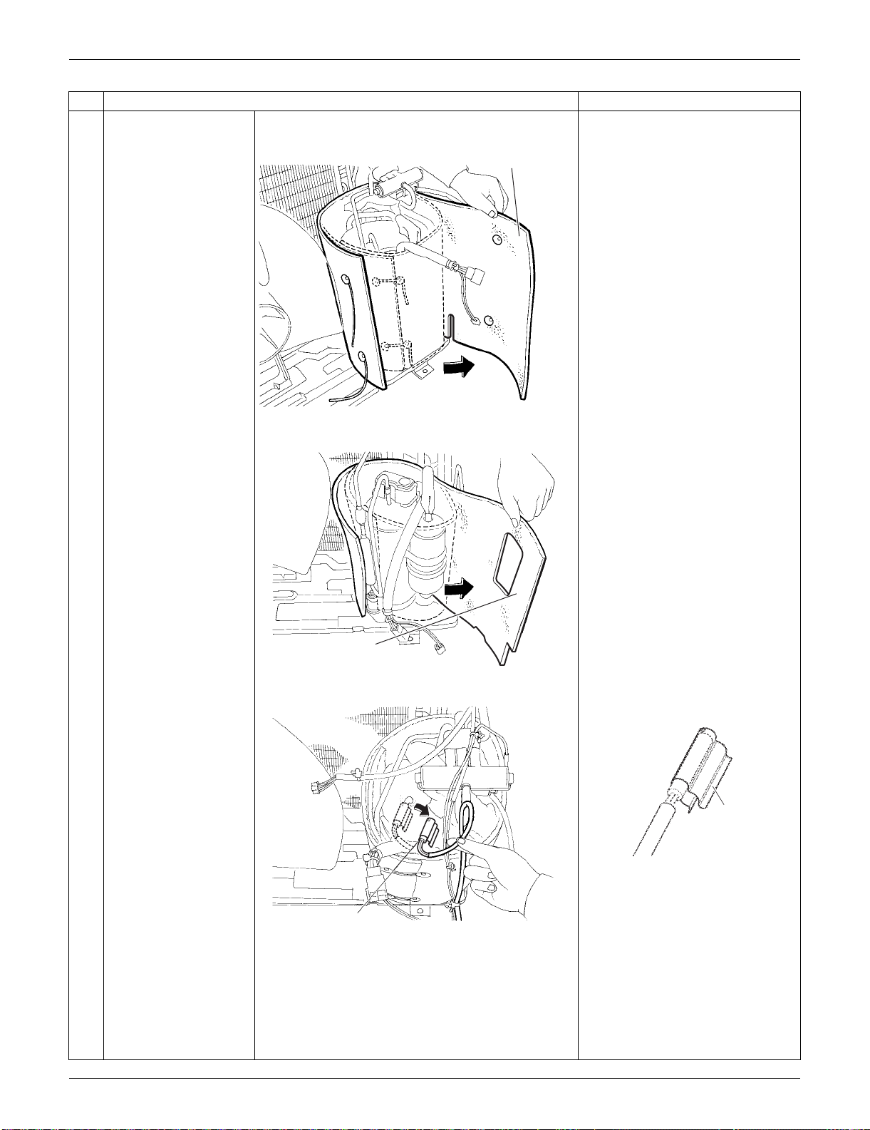
SiUS091133 Outdoor Unit: RXS15/18LVJU
Removal Procedure 318
4
Remove the sound
blanket (outer).
Since the piping ports are torn
easily, remove the sound
blankets carefully.
5
Remove the sound
blanket (inner).
6
Release the discharge
pipe thermistor.
Be careful not to lose the clip for
the thermistor.
Step
Procedure Points
(R16776)
Sound blanket
(outer)
Sound blanket
(inner)
(R16778)
(R12286)
Discharge pipe thermistor
(R12287)
Clip
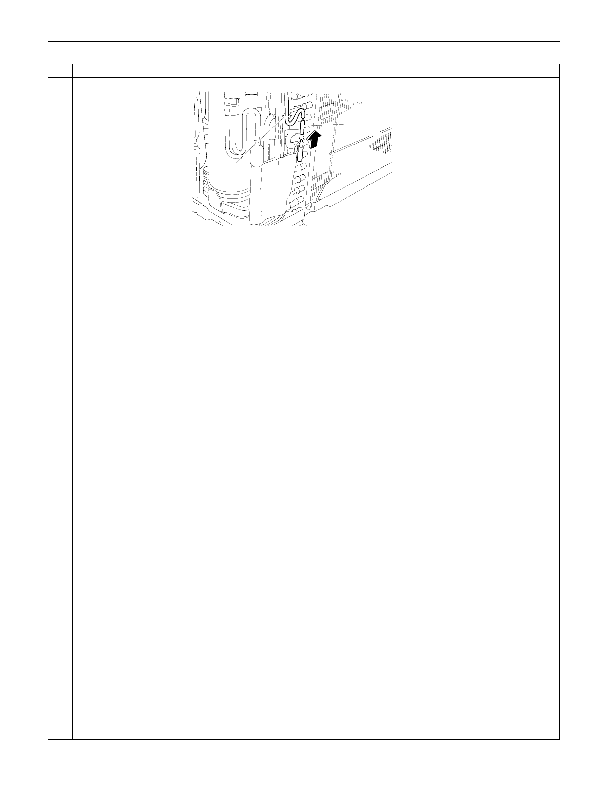
Outdoor Unit: RXS15/18LVJU SiUS091133
319 Removal Procedure
7
Cut the clamp and pull
out the
outdoor heat
exchanger thermistor.
Step
Procedure Points
Outdoor heat
exchanger
thermistor
(R5292)
Clamp
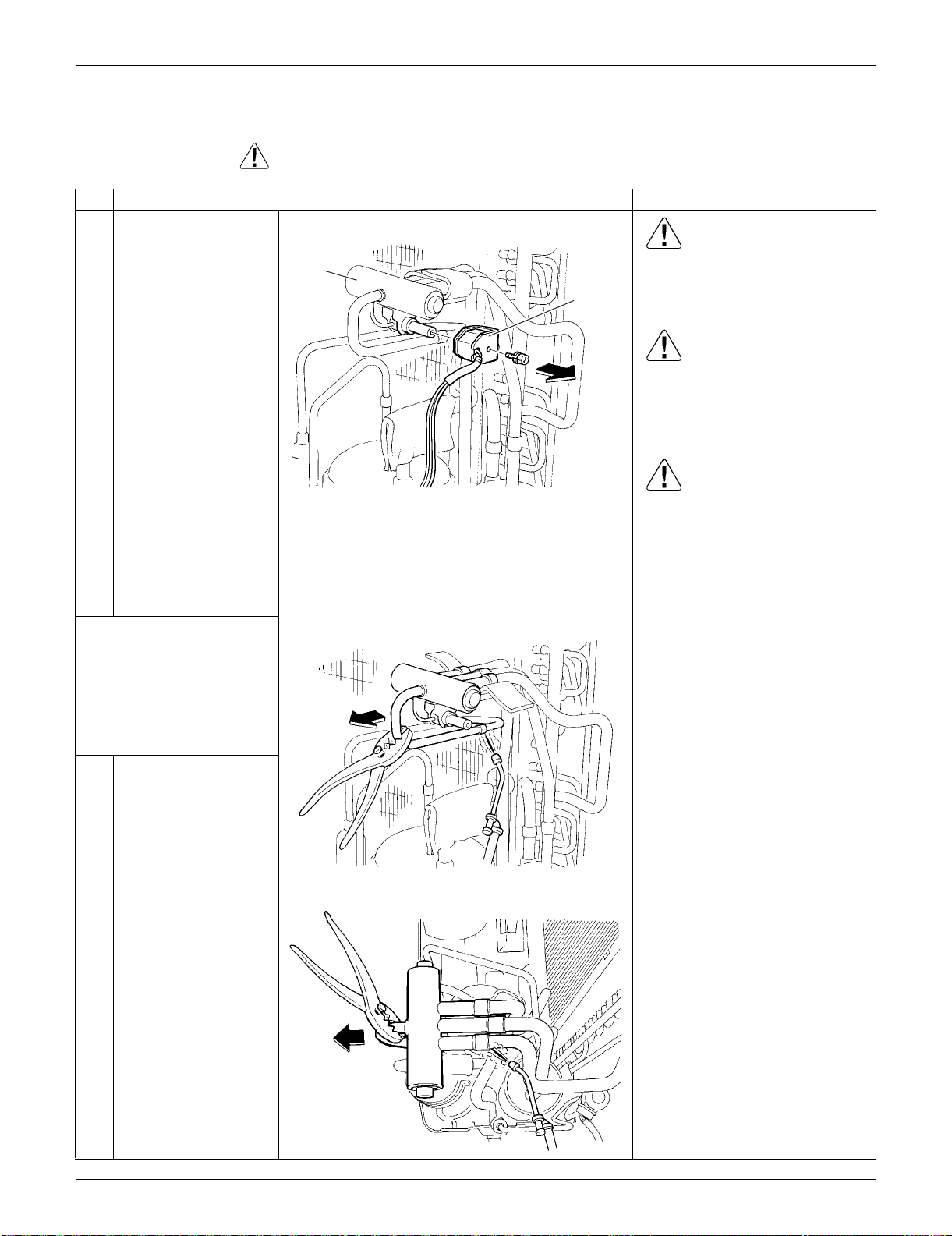
SiUS091133 Outdoor Unit: RXS15/18LVJU
Removal Procedure 320
5.6 Removal of Four-Way Valve
Procedure Warning Be sure to wait for 10 minutes or more after turning off all power supplies
before disassembling work.
Step
Procedure Points
1
Remove the screw and
remove the four-way
valve coil.
Warning
Be careful not to get yourself
burnt with the pipes and other
parts that are heated by the gas
brazing machine.
Warning
If the refrigerant gas leaks during
work, ventilate the room. (If the
refrigerant gas is exposed to
flames, toxic gas may be
generated.)
Caution
From the viewpoint of global
environment protection, do not
discharge the refrigerant gas in
the atmosphere. Make sure to
collect all the refrigerant gas.
Cautions for restoration
1. Restore the piping by non-
oxidation brazing.
2. It is required to prevent the
carbonization of the oil inside
the four-way valve and the
deterioration of the gaskets
affected by heat. (Keep below
120°C (248°F).) For the sake of
this, wrap the four-way valve
with wet cloth and provide water
so that the cloth does not dry.
Note:
Never use a metal saw to cut
pipes because the sawdust may
enter the circuit.
When withdrawing the pipes, be
careful not to pinch them firmly
with pliers. The pipes may get
deformed.
Provide a protective sheet or a
steel plate so that the brazing
flame cannot influence
peripheries.
Before working, make
sure that the refrigerant
gas is empty in the circuit.
Be sure to apply nitrogen
replacement when
heating up the brazed
part.
2
Remove the putty. Heat
up the brazed part of
the four-way valve and
disconnect.
3
Heat up every brazed
part in turn and
disconnect.
Four way
valve coil
Four way
valve
(R5297)
(R5298)
(R5299)
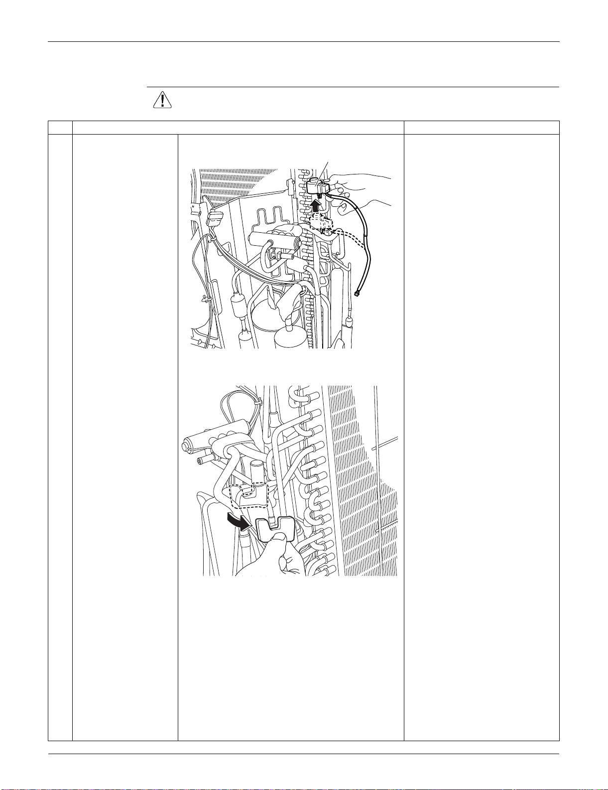
Outdoor Unit: RXS15/18LVJU SiUS091133
321 Removal Procedure
5.7 Removal of Electronic Expansion Valve
Procedure Warning Be sure to wait for 10 minutes or more after turning off all power supplies
before disassembling work.
Step
Procedure Points
1
Pull out the electronic
expansion valve coil.
2
Remove the sheets of
putty.
(R16751)
Electronic expansion valve coil
(R16752)
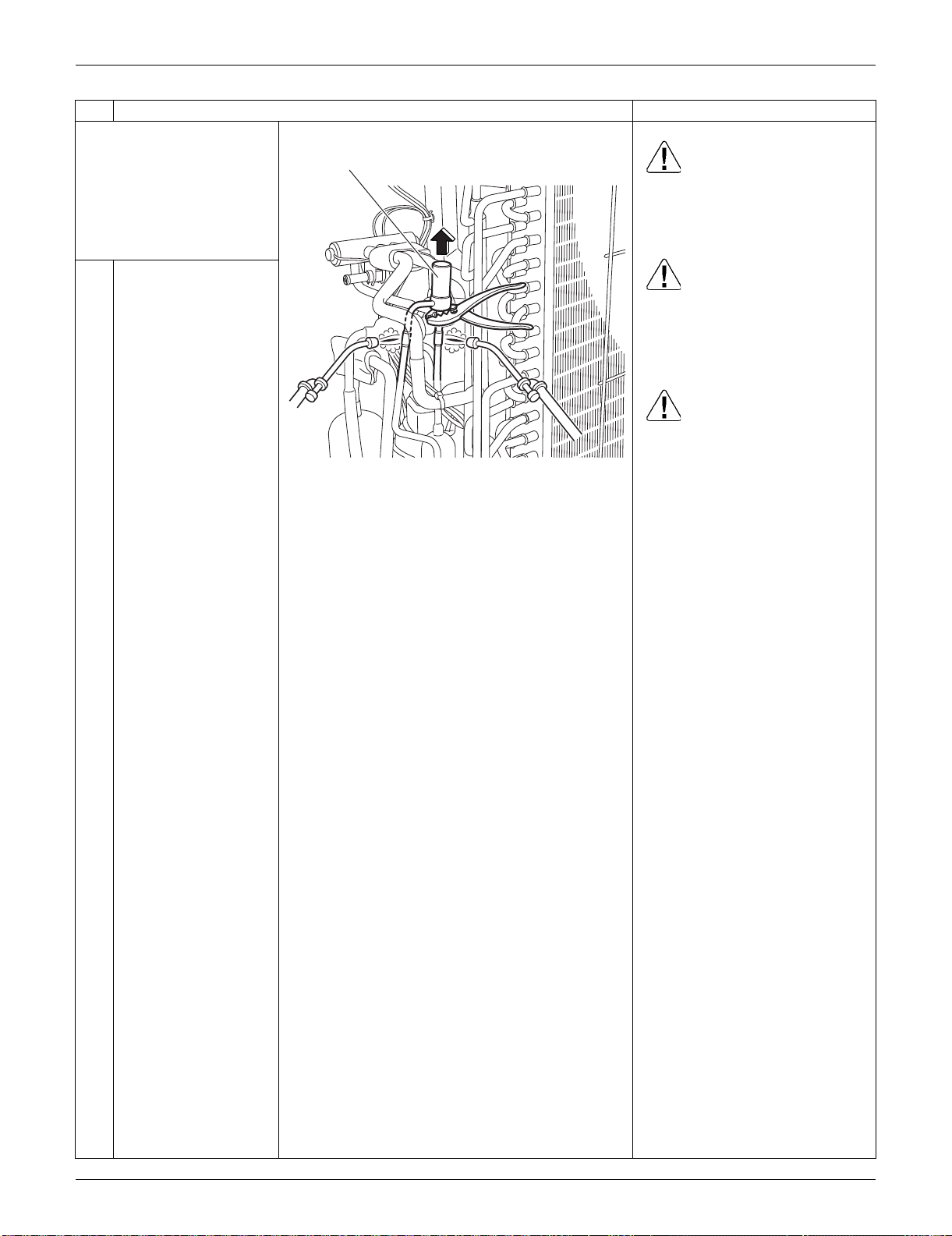
SiUS091133 Outdoor Unit: RXS15/18LVJU
Removal Procedure 322
Before working, make
sure that the refrigerant
gas is empty in the circuit.
Be sure to apply nitrogen
replacement when
heating up the brazed
part.
Warning
Use caution to avoid burning
yourself with pipes and other
parts that are heated by the gas
brazing.
Warning
If the refrigerant gas leaks during
work, immediately ventilate the
room. If refrigerant gas is
exposed to flames, toxic gas may
be generated.
Caution
For global environmental
protection, do not discharge the
refrigerant gas in the
atmosphere. Make sure to collect
all the refrigerant gas.
3
Heat up the 2 brazed
parts of the electronic
expansion valve and
remove it.
Step
Procedure Points
(R16753)
Electric expansion valve
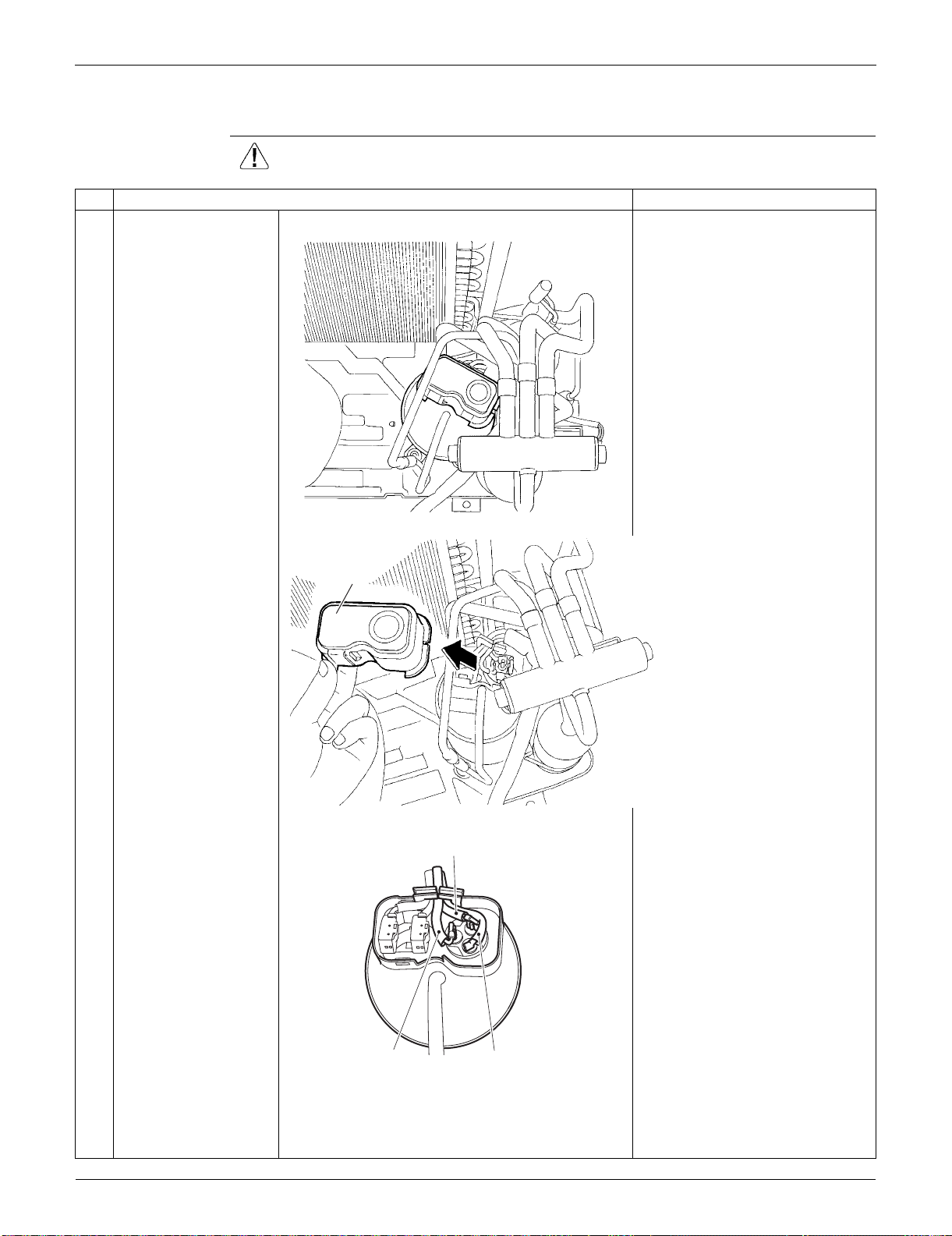
Outdoor Unit: RXS15/18LVJU SiUS091133
323 Removal Procedure
5.8 Removal of Compressor
Procedure Warning Be sure to wait for 10 minutes or more after turning off all power supplies
before disassembling work.
Step
Procedure Points
1
Remove the terminal
cover.
2
Disconnect the lead
wires of the
compressor.
(R5301)
Terminal cover
(R5302)
Red (U)
Yellow (V)
Blue (W)
(R16784)
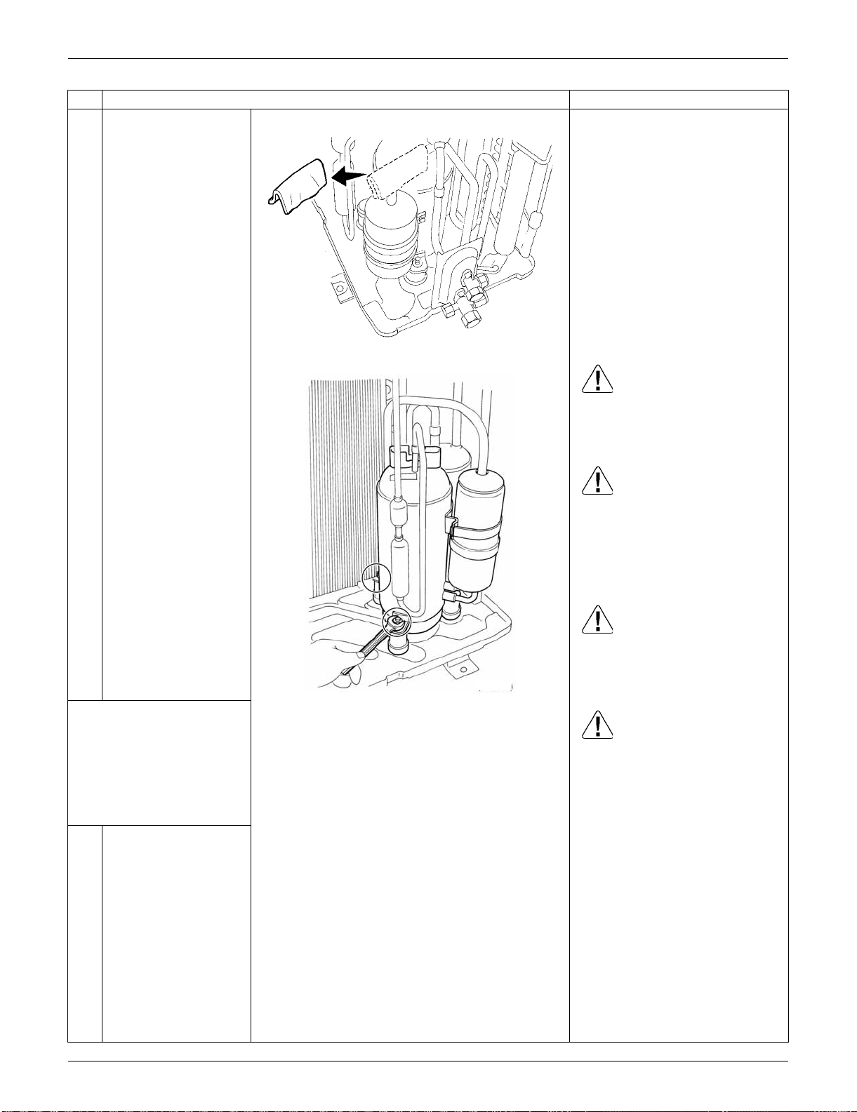
SiUS091133 Outdoor Unit: RXS15/18LVJU
Removal Procedure 324
3
Remove the putty.
Warning
Use caution to avoid burning
yourself with pipes and other
parts that are heated by the gas
brazing
Warning
If the refrigerant gas leaks during
work, immediately ventilate the
room. If refrigerant gas is
exposed to flames, toxic gas may
be generated.
Warning
If the refrigerant oil in the
compressor catches fire, have a
wet cloth prepared to extinguish
the fire immediately.
Caution
For global environmental
protection, do not discharge the
refrigerant gas in the
atmosphere. Make sure to collect
all the refrigerant gas.
4
Remove the 2 nuts of
the compressor.
Before working, make
sure that the refrigerant
gas is empty in the circuit.
Be sure to apply nitrogen
replacement when
heating up the brazed
part.
Step
Procedure Points
(R16963)
(R10257)
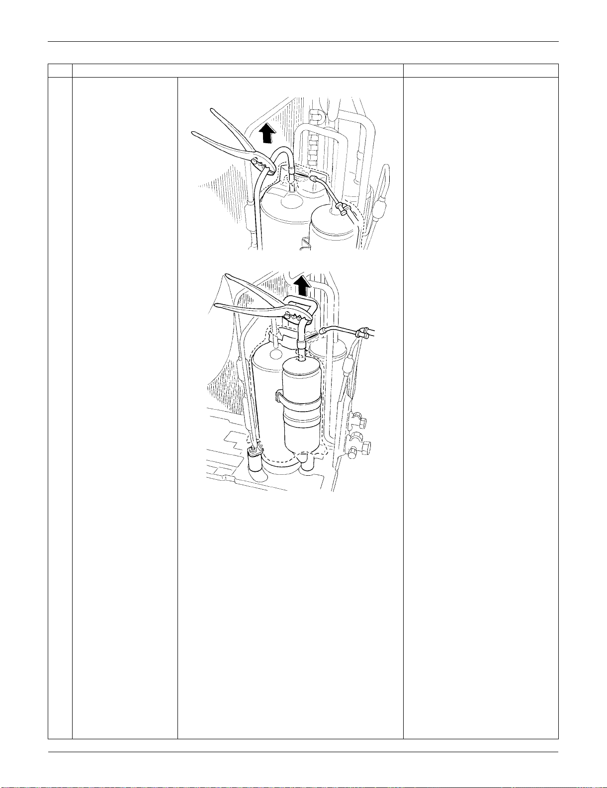
Outdoor Unit: RXS15/18LVJU SiUS091133
325 Removal Procedure
5
Heat up the brazed part
of the discharge side
and disconnect it.
Cautions for restoration
1. Restore the piping by non-
oxidation brazing.
2. It is required to prevent the
carbonization of the oil inside
the four-way valve and the
deterioration of the gaskets
affected by heat. Keep below
120°C (248°F). Wrap the four-
way valve with a wet cloth and
provide water so that the cloth
does not dry.
In case of difficulty with gas
brazing machine
1. Disconnect the brazed part
where is easy to disconnect and
restore.
2. Cut pipes on the main unit with
a tube cutter in order to make it
easy to disconnect.
Note:
Never use a metal saw to cut
pipes because the sawdust may
enter the circuit.
When withdrawing the pipes, be
careful not to pinch them firmly
with pliers. The pipes may get
deformed.
Provide a protective sheet or a
steel plate so that the brazing
flame cannot influence
peripheries.
Be careful so as not to burn the
compressor terminals, the name
plate, the heat exchanger fin.
6
Heat up the brazed part
of the suction side and
disconnect it.
7
Lift the compressor up
and remove it.
Step
Procedure Points
(R5308)
(R5309)

SiUS091133 Outdoor Unit: RXS24LVJU
Removal Procedure 326
6. Outdoor Unit: RXS24LVJU
6.1 Removal of Outer Panels
Procedure Warning Be sure to wait for 10 minutes or more after turning off all power supplies
before disassembling work.
Step
Procedure Points
1. Appearance features
2. Remove the suction grille. The hooks are secured in the
clearances of the outdoor heat
exchanger fins.
1
Unfasten the 2 hooks at
the bottom first.
2
Slide the suction grille
downward to unfasten
the 3 top hooks.
(R16578)
Hook
Rear side Suction grille
(R16916)
Hook
(R16917)
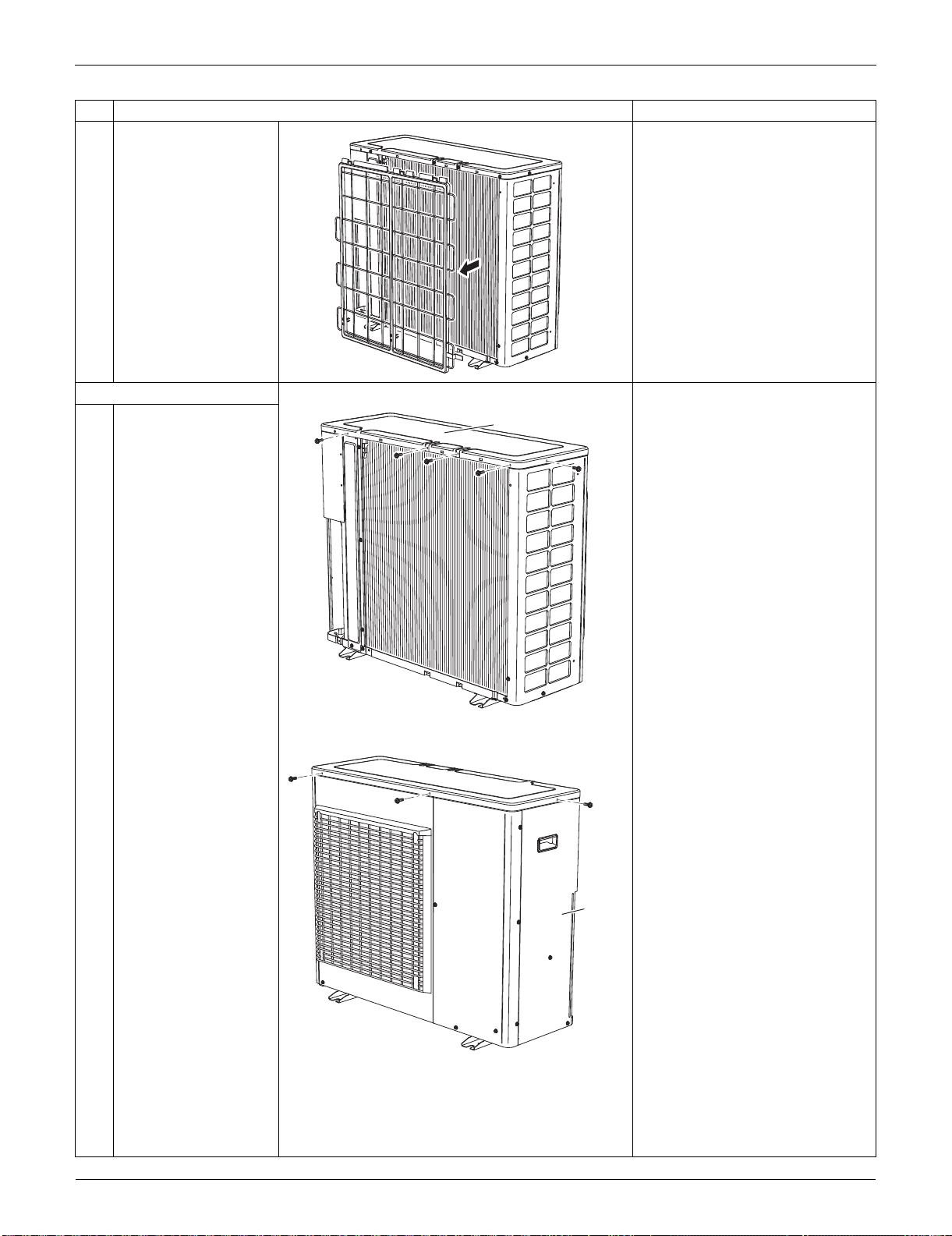
Outdoor Unit: RXS24LVJU SiUS091133
327 Removal Procedure
3
Remove the suction
grille.
3. Remove the top panel.
1
Remove the 4 screws
on the back and the
screw on the left side.
2
Remove the 2 screws
on the front and the
screw on the right side
panel.
Step
Procedure Points
(R6372)
(R6373)
Top panel
(R16579)
Right
side
panel
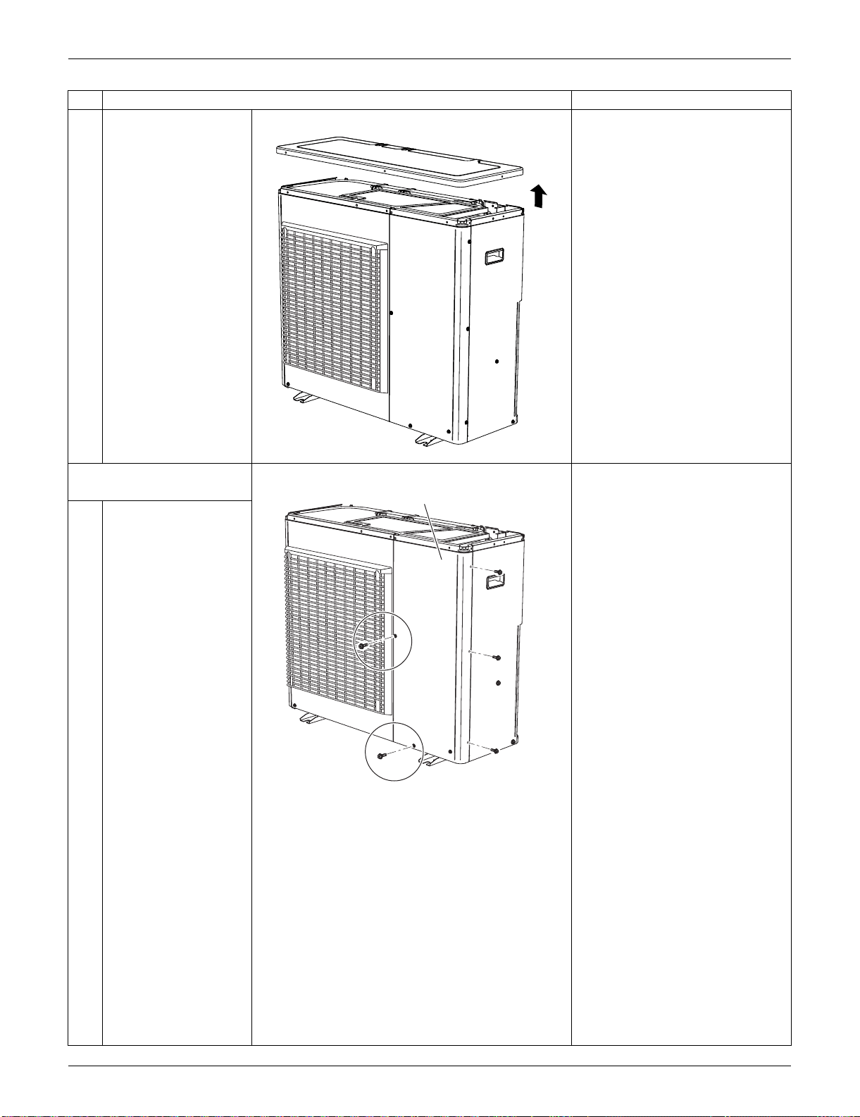
SiUS091133 Outdoor Unit: RXS24LVJU
Removal Procedure 328
3
Lift the top panel and
remove it.
4. Remove the front panel
(2).
:This screw is M5(3) × 16
1
Remove the 5 screws.
Step
Procedure Points
(R16580)
(R17006)
Front Panel (2)
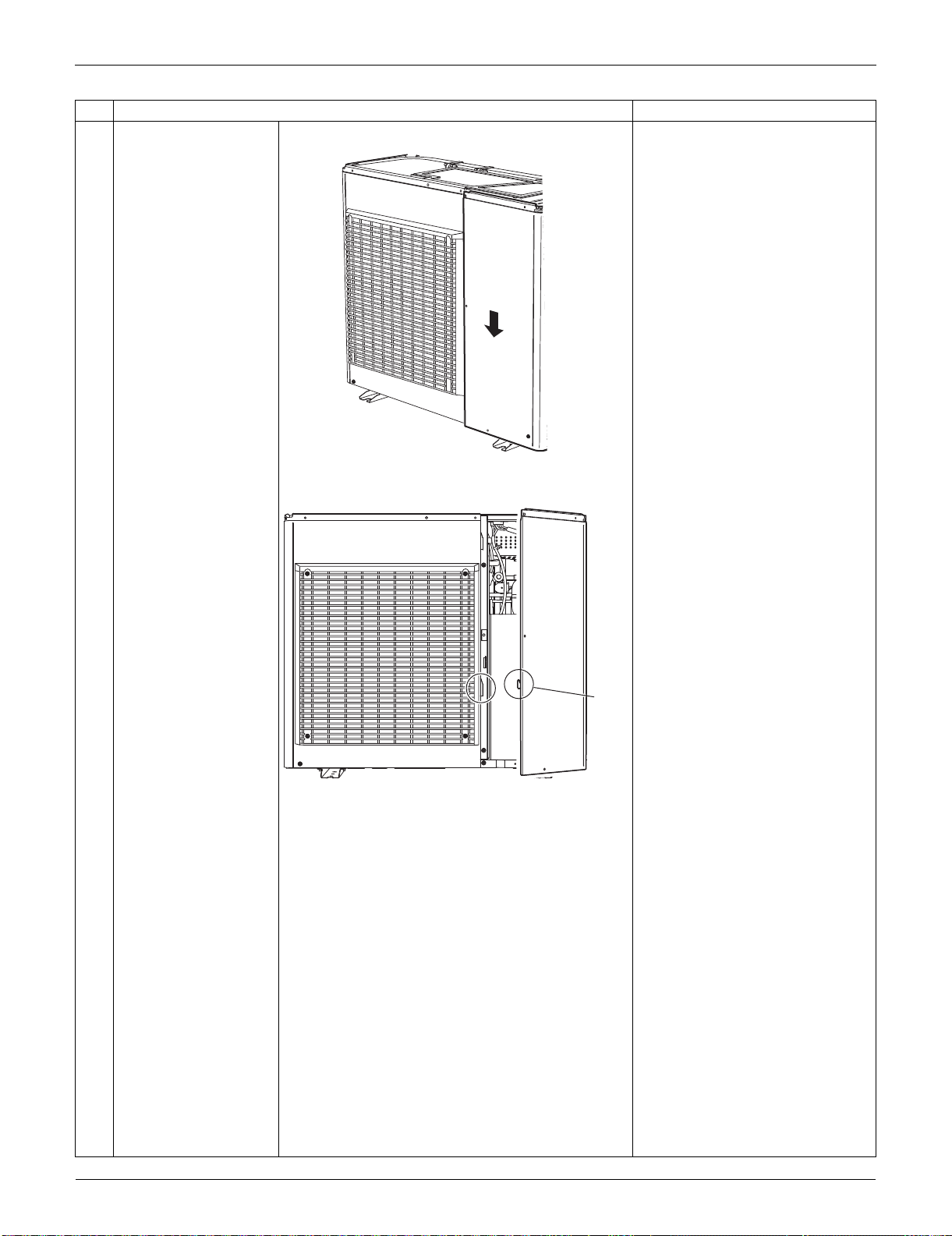
Outdoor Unit: RXS24LVJU SiUS091133
329 Removal Procedure
2
Slide the front panel (2)
downward to unfasten
the hook.
3
Remove the front panel
(2).
Step
Procedure Points
(R16582)
(R16583)
Hook
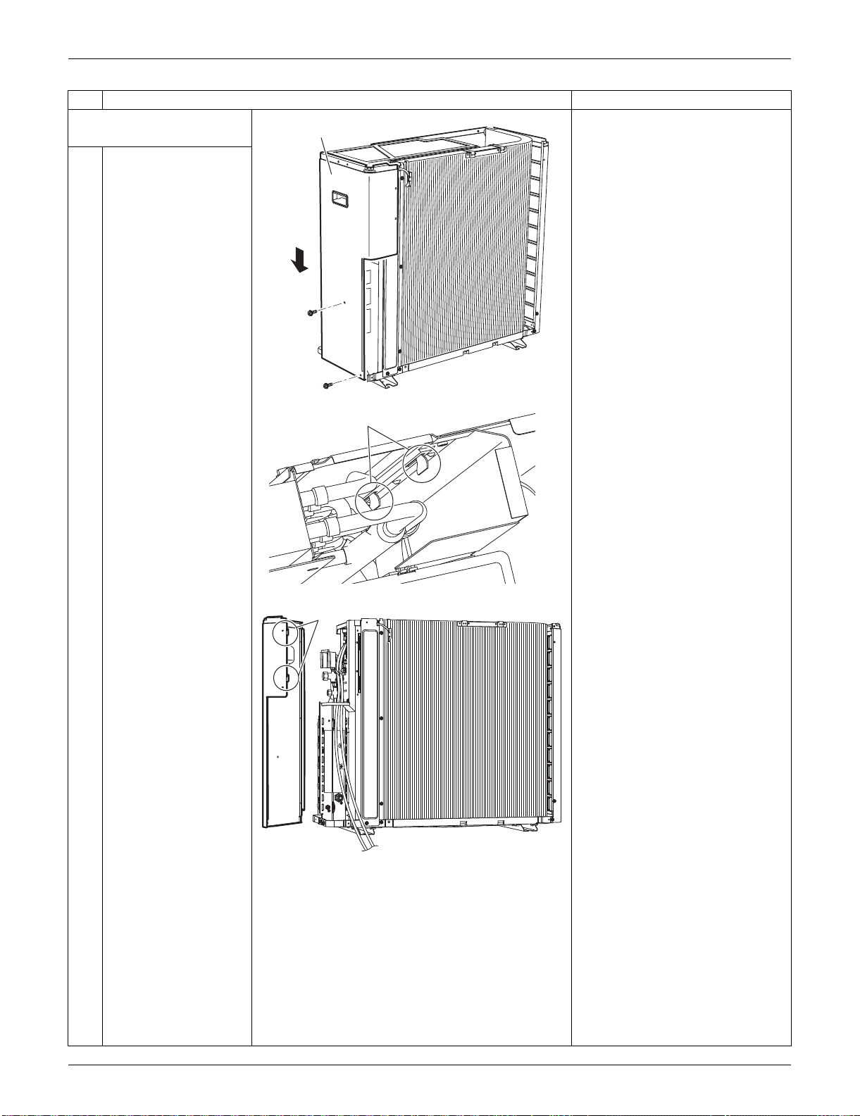
SiUS091133 Outdoor Unit: RXS24LVJU
Removal Procedure 330
5. Remove the right side
panel.
1
Remove the 2 screws.
Slide the right side
panel downward to
unfasten the 2 hooks on
the rear side.
Step
Procedure Points
(R16728)
Right side panel
Hook
(R13521)
Hook
(R16729)
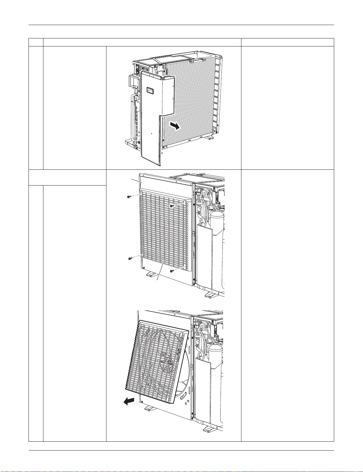
Outdoor Unit: RXS24LVJU SiUS091133
331 Removal Procedure
2
Remove the right side
panel.
6. Remove the front panel
(1).
Remove the discharge grille and
the outdoor fan first to remove
the front panel (1).
1
Remove the 4 screws
on the discharge grille.
2
Pull the bottom of the
discharge grille.
Step
Procedure Points
(R16730)
Discharge grille
(R16587)
Front
Panel (1)
(R16588)
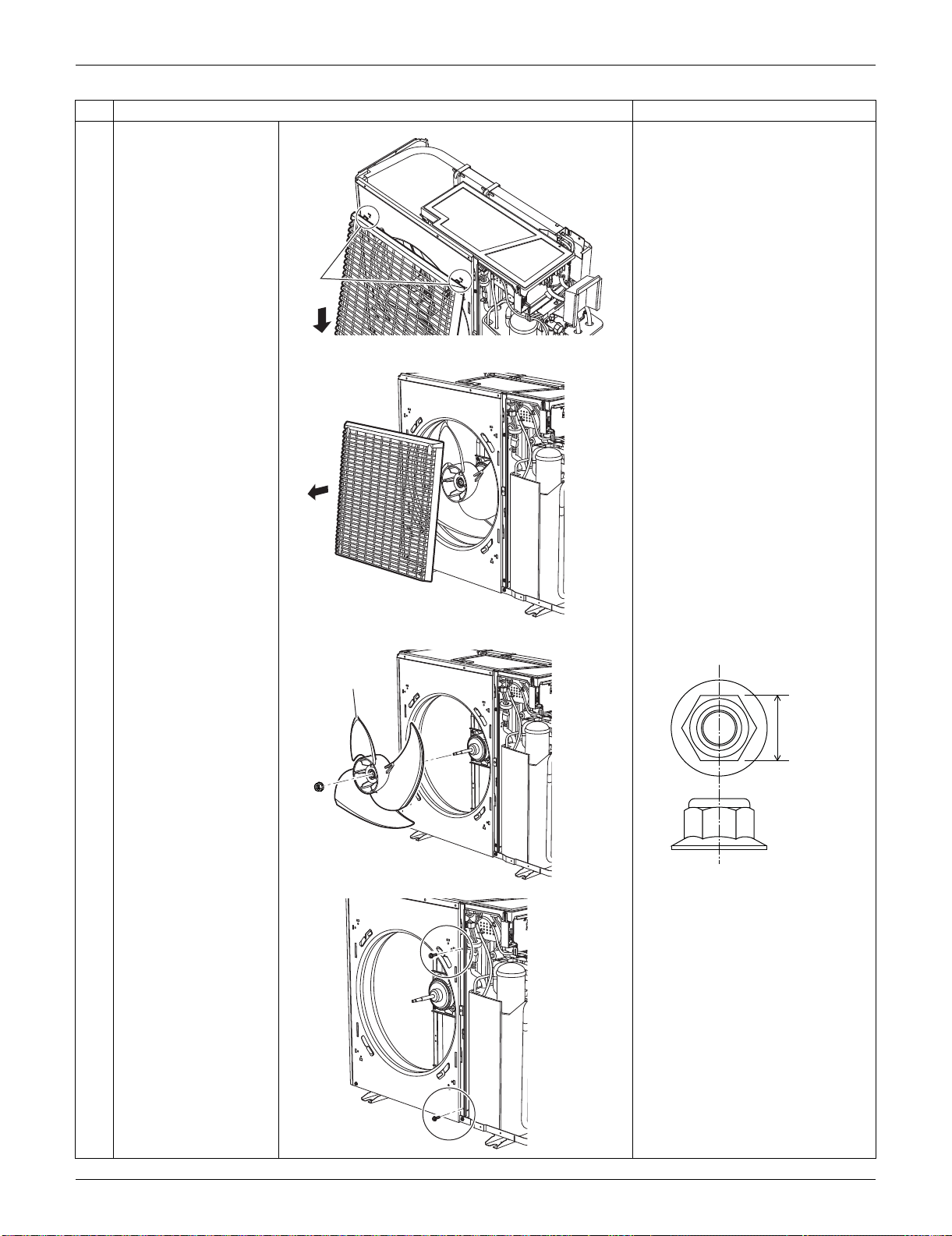
SiUS091133 Outdoor Unit: RXS24LVJU
Removal Procedure 332
3
Slide the discharge
grille downward to
unfasten the 2 hooks at
the top.
4
Remove the discharge
grille.
5
Remove the nut of the
outdoor fan.
Nut size : M8
6
Remove the 2 screws
on the partition plate
(1).
Step
Procedure Points
Hook
(R16591)
(R16592)
Outdoor fan
(R16736)
13 mm
(0.51 inch)
(R17005)
(R16737)
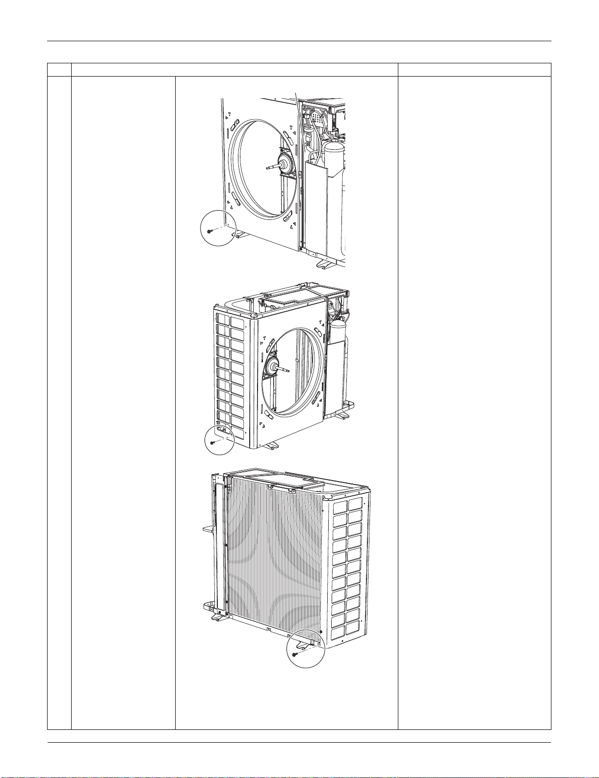
Outdoor Unit: RXS24LVJU SiUS091133
333 Removal Procedure
7
Remove the screw at
the bottom left of the
front.
8
Remove the screw at
the bottom of the left
side.
9
Remove the screw at
the bottom of the rear
side.
Step
Procedure Points
Partition plate (1)
(R16738)
(R16739)
(R6394)
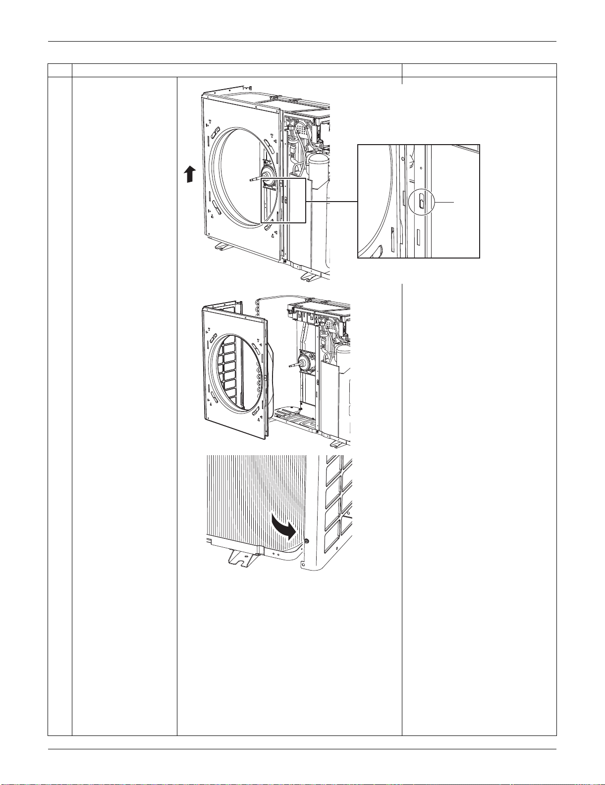
SiUS091133 Outdoor Unit: RXS24LVJU
Removal Procedure 334
10
Lift the front panel (1) to
unfasten the hook.
11
Remove the front panel
(1).
Be sure to detach the front
panel (1) carefully so as not to
deform it.
Step
Procedure Points
Hook
(R16740)
(R16741)
(R6995)
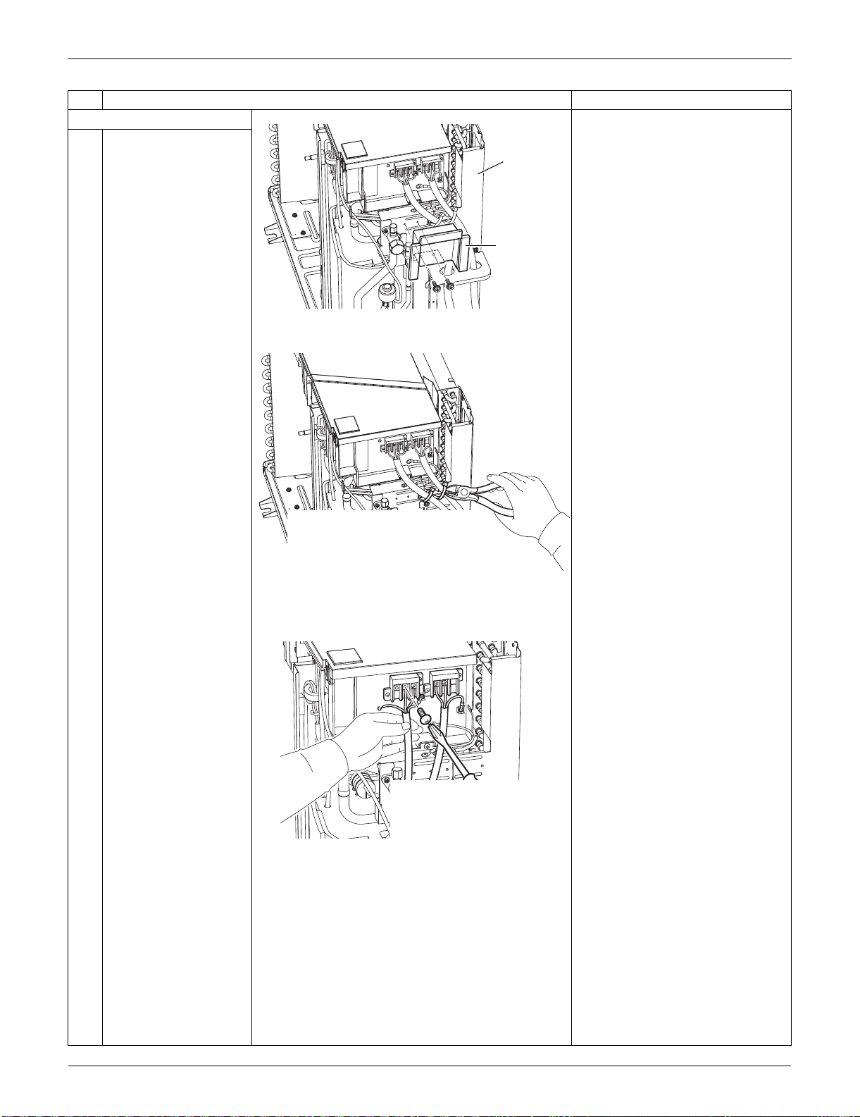
Outdoor Unit: RXS24LVJU SiUS091133
335 Removal Procedure
7. Remove the rear panel.
1
Remove the 2 screws,
and remove the shield
plate ASSY.
2
Release the clamps of
the connection wire.
3
Remove the screws
and detach the
connection wires.
Step
Procedure Points
(R16599)
Rear panel
Shield plate
ASSY
(R17009)
(R17012)
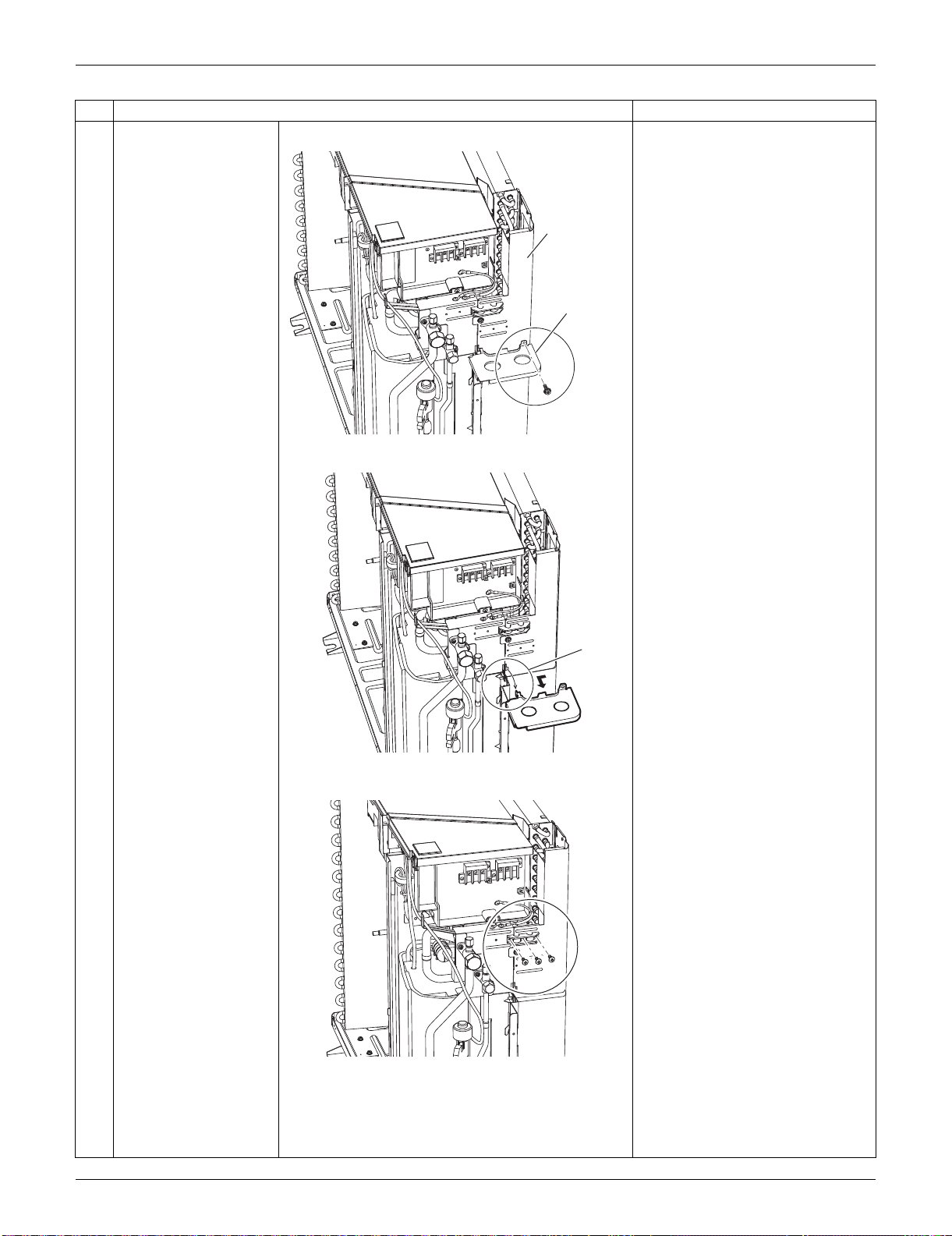
SiUS091133 Outdoor Unit: RXS24LVJU
Removal Procedure 336
4
Remove the screw on
the partition plate (2).
5
Slide the partition plate
(2) to the left, and
remove it.
6
Remove the 3 screws
on the wire fixing plate.
Step
Procedure Points
(R17008)
Rear panel
Partition
plate (2)
(R17007)
Hook
(R17010)
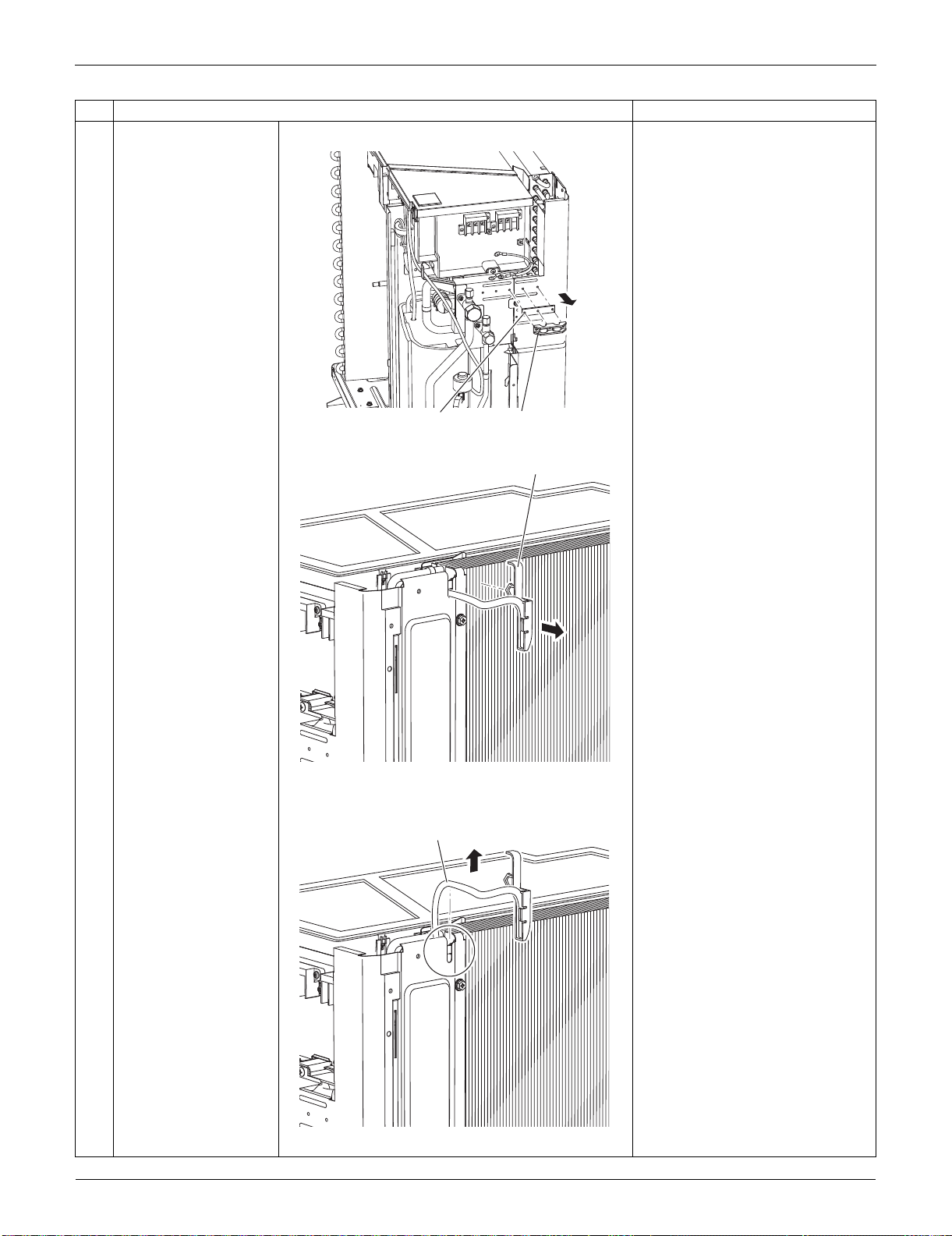
Outdoor Unit: RXS24LVJU SiUS091133
337 Removal Procedure
7
Remove the wire fixing
plate and the insulation.
8
Release the holder of
the outdoor
temperature thermistor.
The holder is secured in the
clearances of the outdoor heat
exchanger fins.
9
Release the harness of
the outdoor
temperature thermistor
from the groove.
Step
Procedure Points
Wire fixing plate
Insulation
(R17011)
Holder
(R11151)
Thermistor
(R14991)
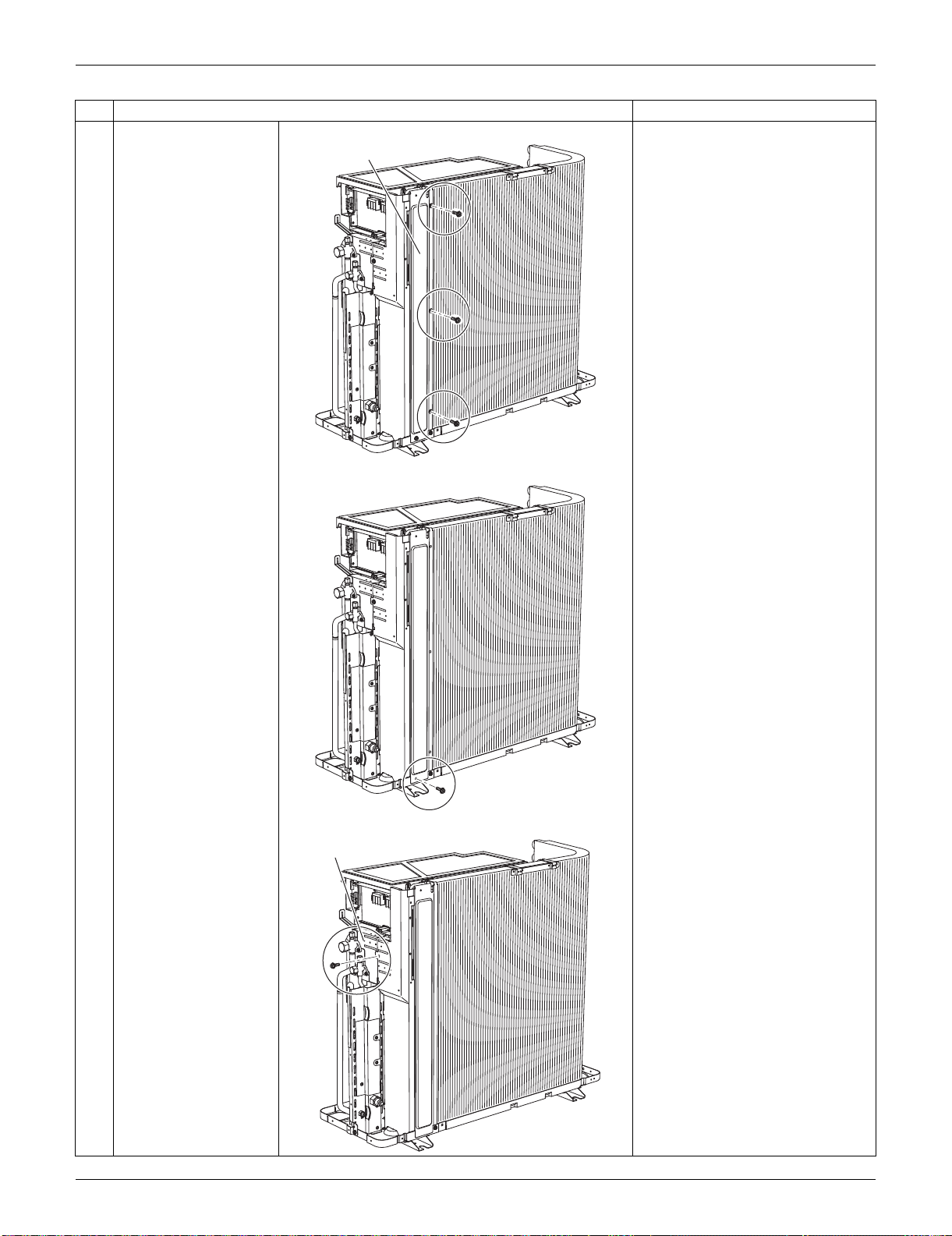
SiUS091133 Outdoor Unit: RXS24LVJU
Removal Procedure 338
10
Remove the 3 screws
on the rear panel.
11
Remove the screw on
the bottom frame.
12
Remove the screw on
the stop valve mounting
plate.
Step
Procedure Points
Rear panel
(R16699)
(R16700)
Stop valve mounting plate
(R16701)
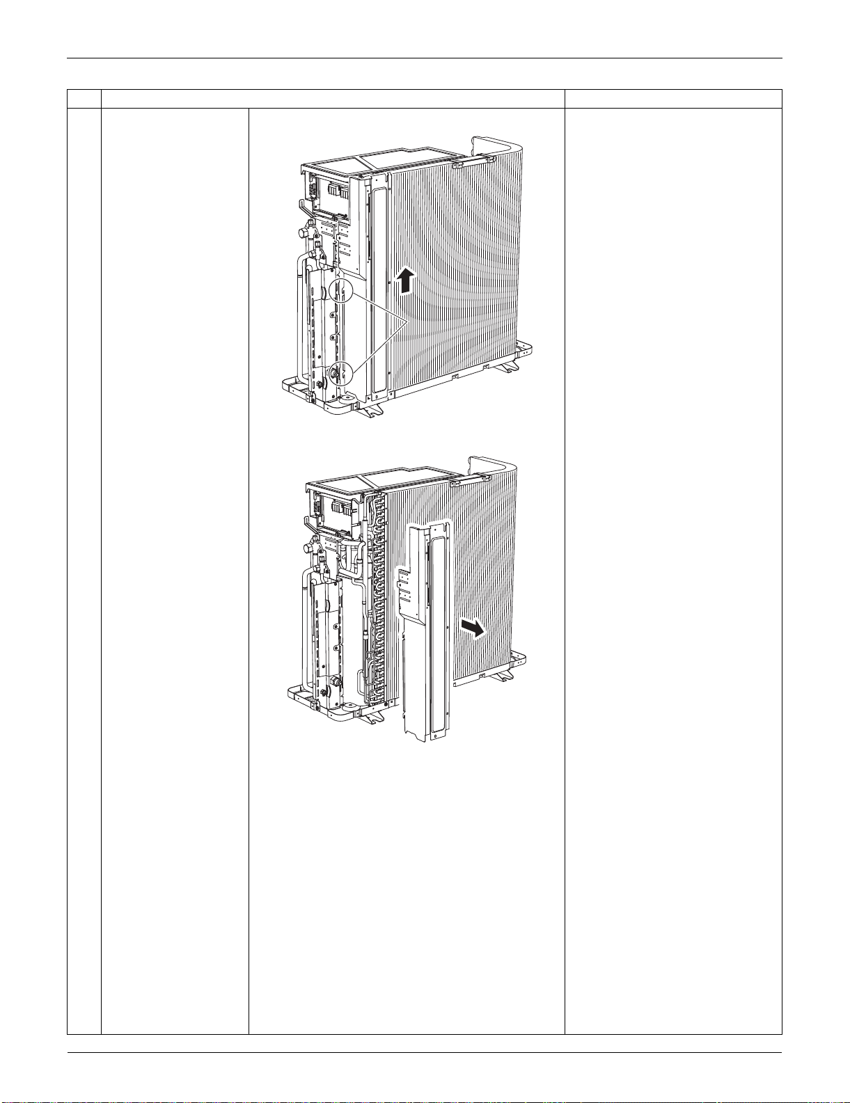
Outdoor Unit: RXS24LVJU SiUS091133
339 Removal Procedure
13
Lift the rear panel
upward to unfasten the
2 hooks.
14
Remove the rear panel.
Step
Procedure Points
HookHook
(R16702)
(R16703)
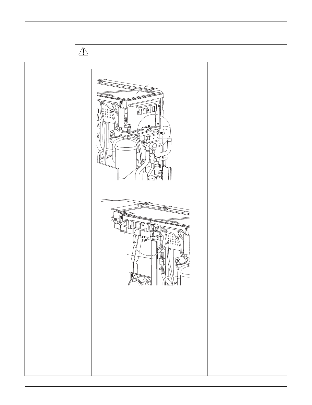
SiUS091133 Outdoor Unit: RXS24LVJU
Removal Procedure 340
6.2 Removal of Electrical Box
Procedure Warning Be sure to wait for 10 minutes or more after turning off all power supplies
before disassembling work.
Step
Procedure Points
1 Remove the screw on
the stop valve mounting
plate.
2 Remove the screw on
the partition plate (1).
Electrical box
Stop valve
mounting plate
(R16605)
Partition
plate (1)
(R16606)
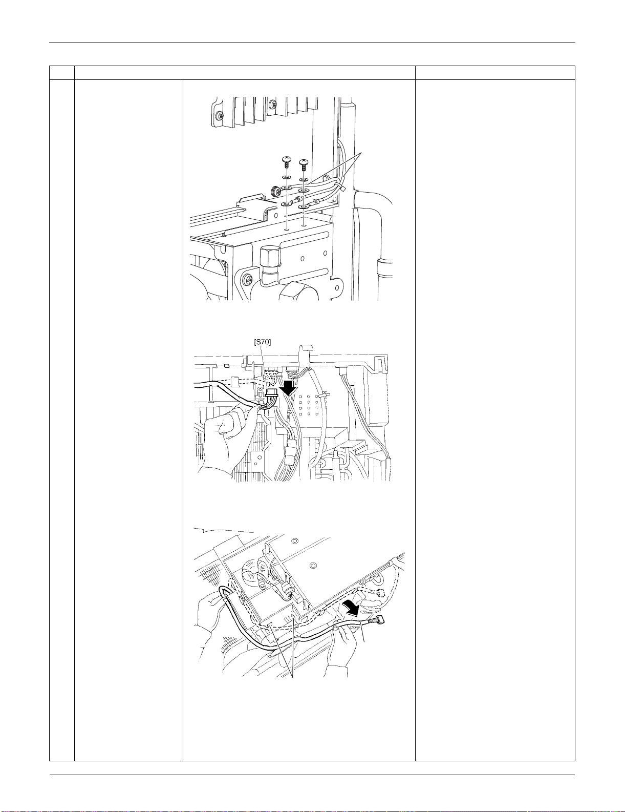
Outdoor Unit: RXS24LVJU SiUS091133
341 Removal Procedure
3 Remove the 2 screws
to detach the ground
wires.
4
Disconnect the
connector for the fan
motor [S70].
5
Release the fan motor
lead wire from the 5
hooks.
: When reassembling, do not use
these 2 hooks.
Step
Procedure Points
Ground wire
(R16607)
(R7008)
Fan motor
lead wire
(R9468)
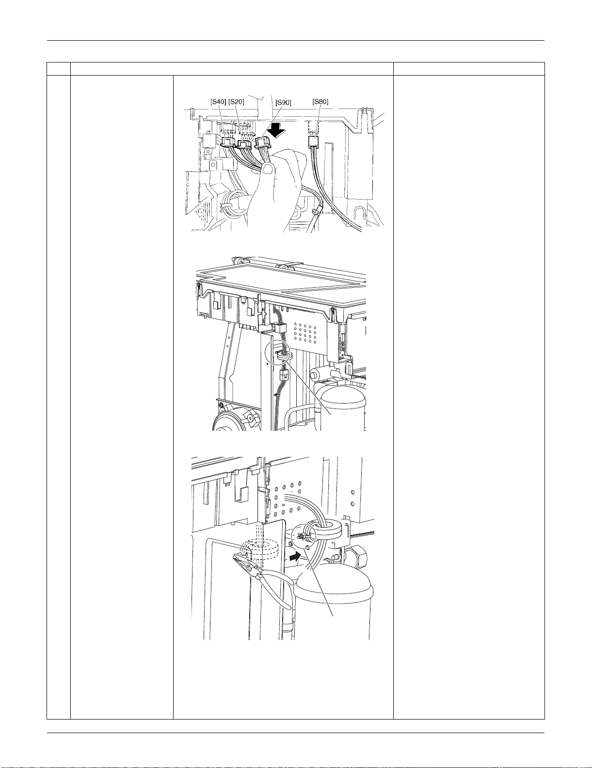
SiUS091133 Outdoor Unit: RXS24LVJU
Removal Procedure 342
6
Disconnect the
connectors of the front
side.
[S20]: electronic expansion valve
coil
[S40]: overload protector
[S80]: four-way valve coil
[S90]: thermistors
7 The compressor lead
wire is fixed on the
partition plate (1) with a
clamp.
8 Release the clamp of
the compressor relay
harness with pliers.
Step
Procedure Points
(R5275)
Clamp
(R16704)
Clamp
(R6423)
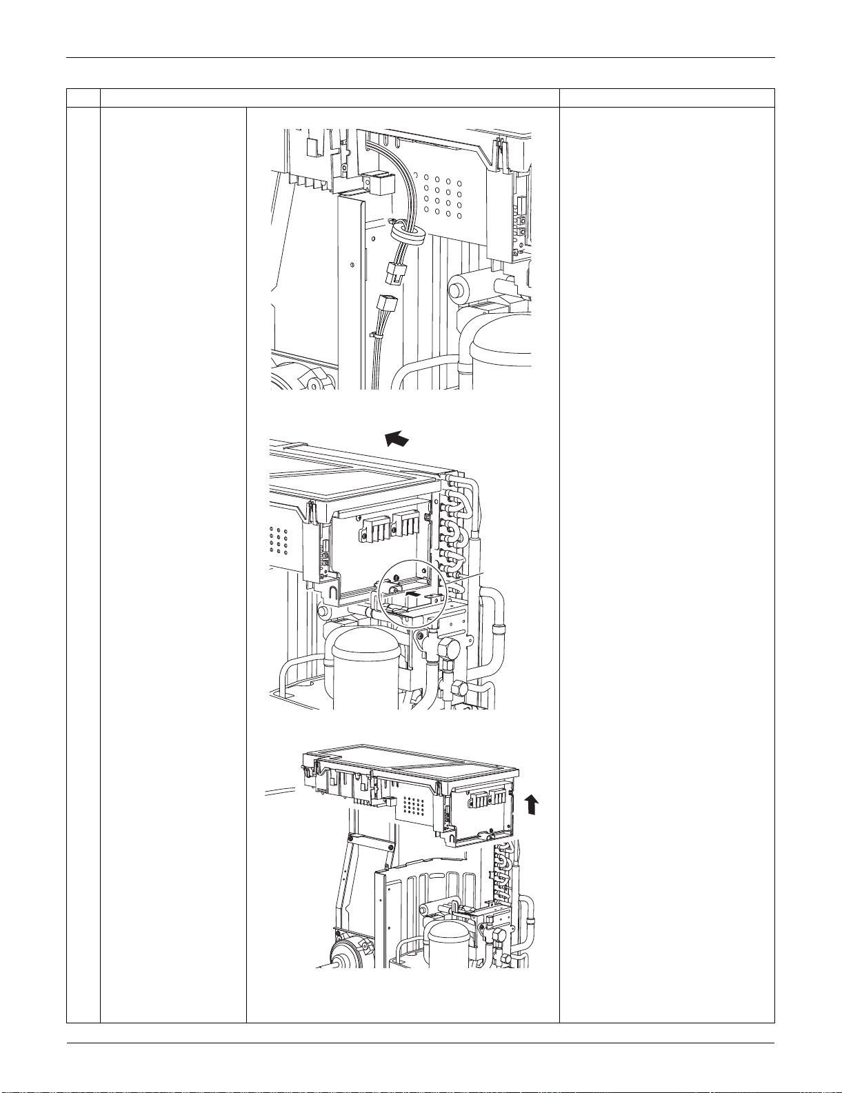
Outdoor Unit: RXS24LVJU SiUS091133
343 Removal Procedure
9 Disconnect the relay
connector for the
compressor.
10 Slide the electrical box
to the left to unfasten
the hook on the right
side of the box.
11 Lift up the electrical box
and remove it.
Step
Procedure Points
(R6469)
(R16705)
Hook
(R16706)
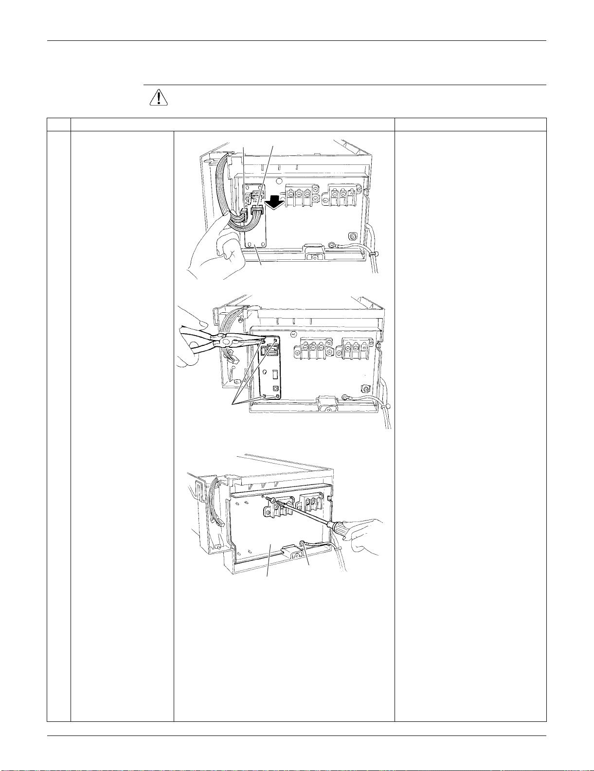
SiUS091133 Outdoor Unit: RXS24LVJU
Removal Procedure 344
6.3 Removal of PCBs
Procedure Warning Be sure to wait for 10 minutes or more after turning off all power supplies
before disassembling work.
Step
Procedure Points
1
Disconnect the
connectors [S52]
[S102] from the service
monitor PCB.
Preparation
Remove the electrical box
according to the "Removal of
Electrical Box".
2
Detach the 4 clamps
with pliers and remove
the service monitor
PCB.
3
Remove the screws of
the terminal board and
the ground wire.
Service monitor PCB
[S52]
[S102]
(R16707)
Clamp
(R16708)
Terminal board
(R16709)
Ground wire
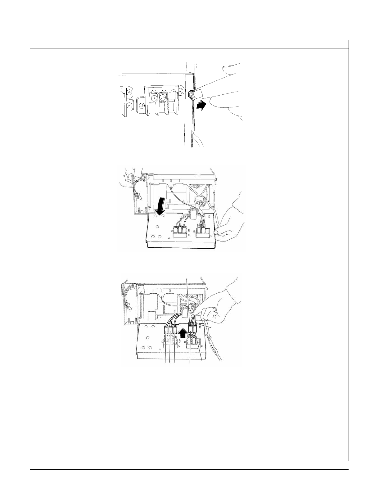
Outdoor Unit: RXS24LVJU SiUS091133
345 Removal Procedure
4
Unfasten the hook on
the right.
5
Open the terminal
board.
6
Disconnect the
harnesses from the
terminal board.
1: Black
2: White
3: Red
L1: Black
L2: Brown
N1: White
N2: Blue
Step
Procedure Points
(R5283)
(R16710)
(R16711)
N2
N1
L1
321
L2
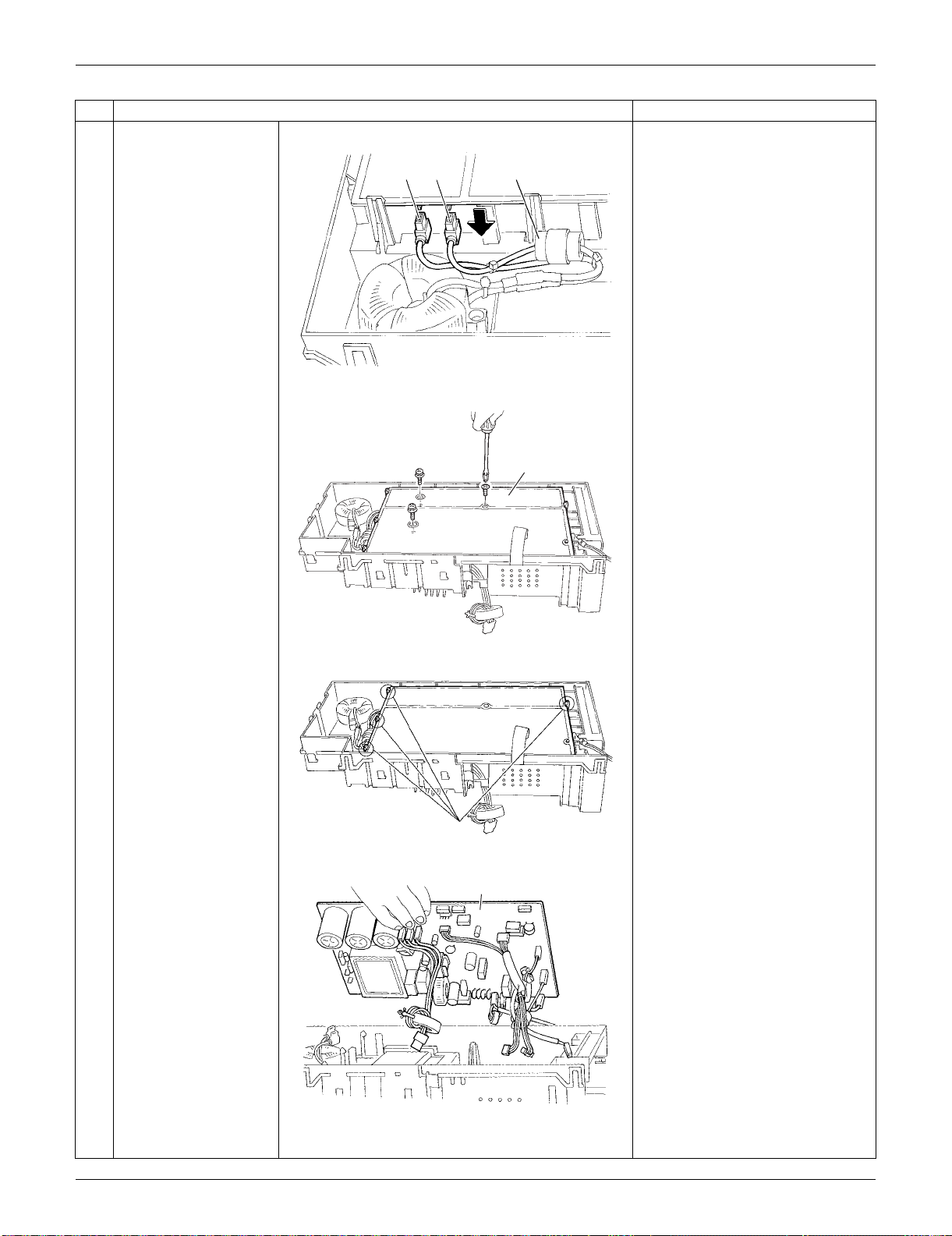
SiUS091133 Outdoor Unit: RXS24LVJU
Removal Procedure 346
7
Disconnect the 2
harnesses for the
reactor [HR1] [HR2].
[HR1] : White
[HR2] : Blue
The harness for [HR2] has a
ferrite core.
8
Remove the 3 screws
of the main PCB.
9
Release the 4 hooks.
10
Lift up and remove the
main PCB.
Refer to page 26 for detail.
Step
Procedure Points
[HR2] Ferrite core[HR1]
(R5286)
Main PCB
(R5287)
Hook
(R13524)
Main PCB
(R5289)
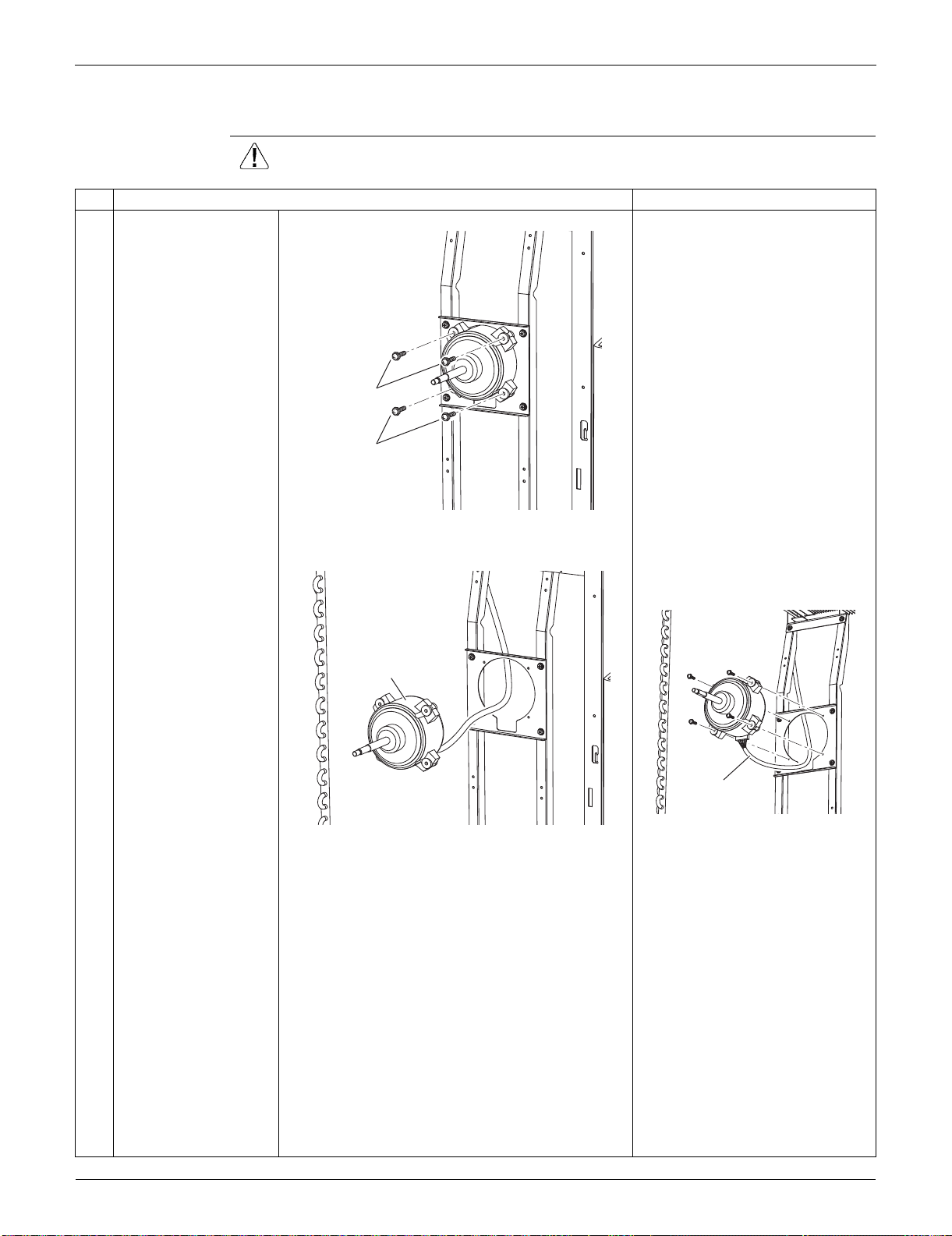
Outdoor Unit: RXS24LVJU SiUS091133
347 Removal Procedure
6.4 Removal of Fan Motor
Procedure Warning Be sure to wait for 10 minutes or more after turning off all power supplies
before disassembling work.
Step
Procedure Points
1
2
Remove the 2 lower
screws first.
Then, remove the 2
upper screws.
Preparation
Remove the electrical box
according to the "Removal of
Electrical Box".
Be sure to remove the lower
screws first. If the top screws
are removed first, the fan motor
may tilt down or fall and cause
injury because its center of
gravity is shifted to the front.
3 Remove the fan motor. When reassembling, make sure
that the wire harness is facing
downward.
2
1
(R6442)
Fan motor
(R6443)
Harness
(R6444)
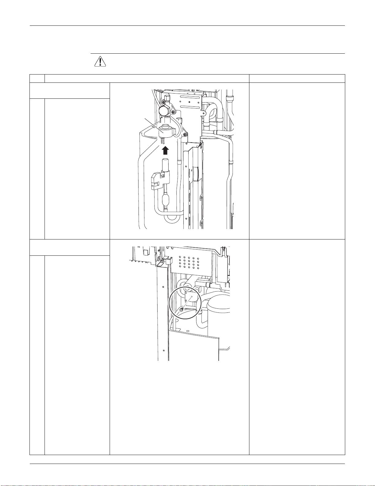
SiUS091133 Outdoor Unit: RXS24LVJU
Removal Procedure 348
6.5 Removal of Coils / Thermistors
Procedure Warning Be sure to wait for 10 minutes or more after turning off all power supplies
before disassembling work.
Step
Procedure Points
1. Remove the electronic
expansion valve coil.
1 Pull the electronic
expansion valve coil
out.
2. Remove the four-way
valve coil.
1 Remove the screw.
Electronic
expansion
valve coil
(R11159)
(R6457)
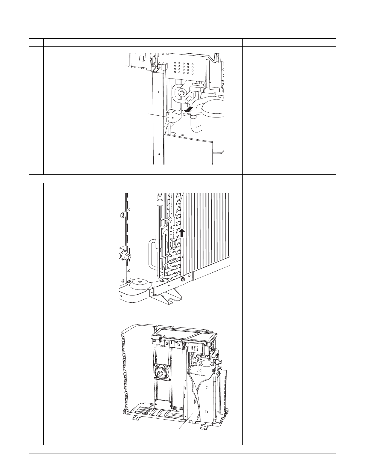
Outdoor Unit: RXS24LVJU SiUS091133
349 Removal Procedure
2 Remove the four-way
valve coil.
3. Remove the thermistors.
1
Pull out the outdoor
heat exchanger
thermistor.
2
Slightly open the sound
blanket (outer).
Step
Procedure Points
Four way
valve coil
(R6458)
Outdoor heat exchanger thermistor
(R11160)
Sound blanket (outer)
(R7011)
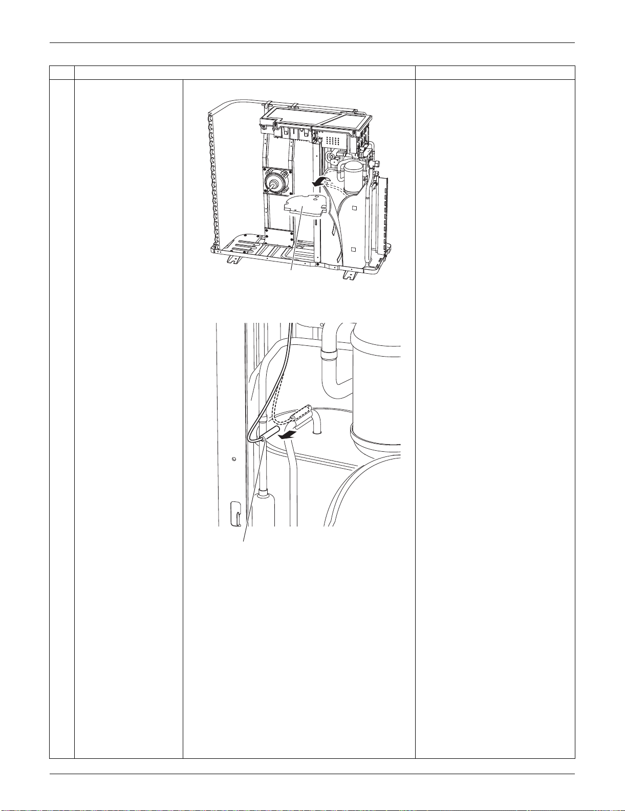
SiUS091133 Outdoor Unit: RXS24LVJU
Removal Procedure 350
3
Remove the sound
blanket (upper top).
4
Remove the discharge
pipe thermistor.
Step
Procedure Points
Sound blanket (upper top)
(R7012)
Discharge pipe thermistor
(R9469)
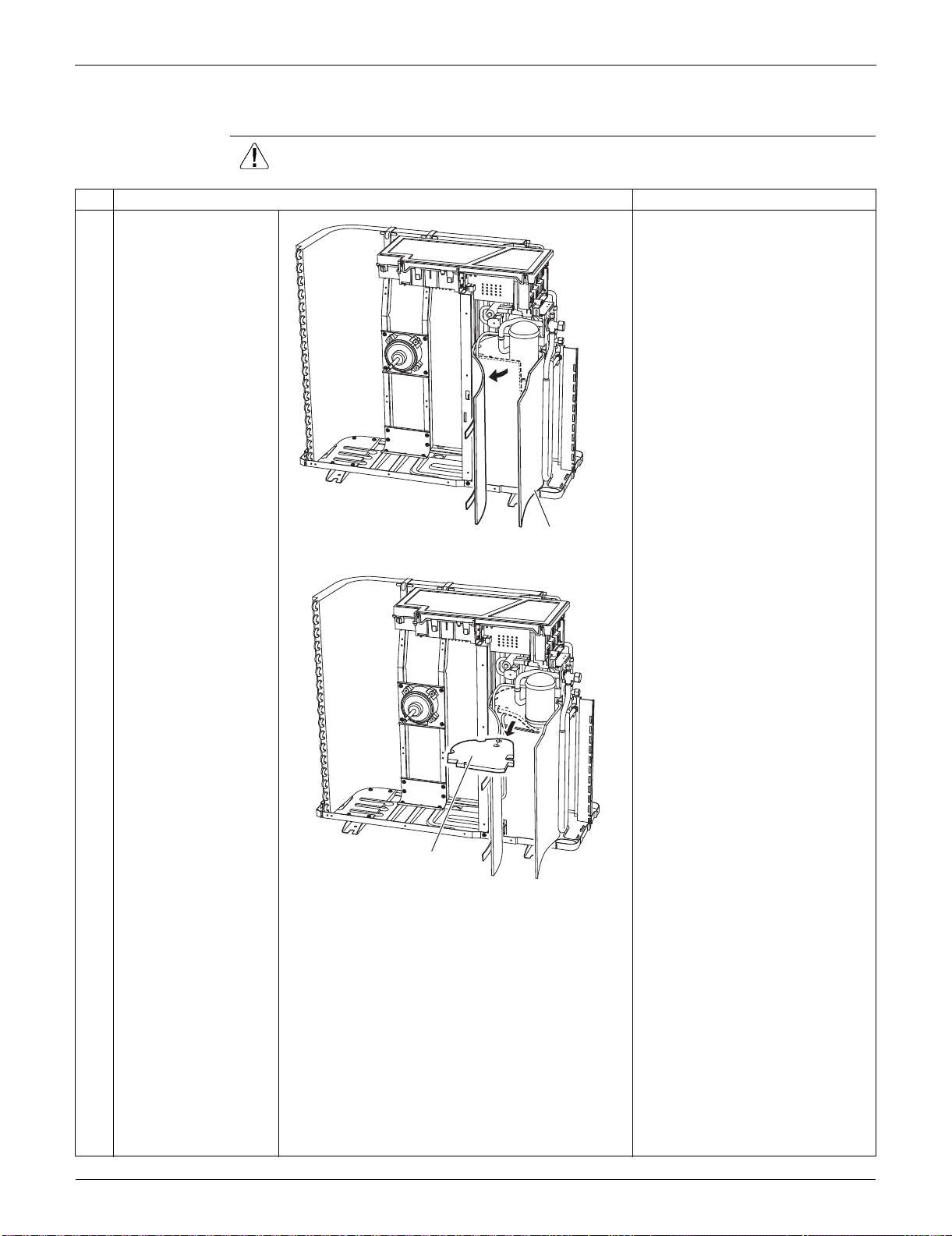
Outdoor Unit: RXS24LVJU SiUS091133
351 Removal Procedure
6.6 Removal of Sound Blankets
Procedure Warning Be sure to wait for 10 minutes or more after turning off all power supplies
before disassembling work.
Step
Procedure Points
1
Open the sound blanket
(outer).
2
Remove the sound
blanket (top upper).
The sound blanket is fragile.
Carefully pass the discharge
pipe through it.
Sound blanket (outer)
(R16608)
Sound blanket (top upper)
(R16609)
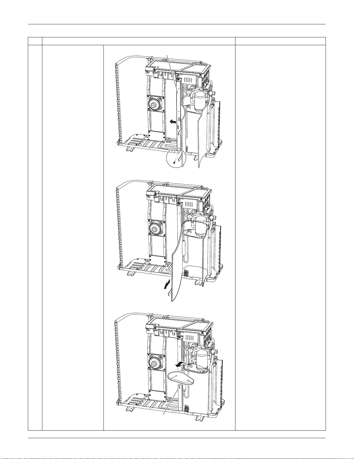
SiUS091133 Outdoor Unit: RXS24LVJU
Removal Procedure 352
3
Remove the screw and
slightly push the
partition plate (1) to the
left for easy work.
4
Remove the sound
blanket (outer).
5
Remove the sound
blanket (top lower).
The sound blanket is fragile.
Carefully pass the discharge
pipe through it.
Step
Procedure Points
Partition plate (1)
(R16610)
(R16611)
Sound blanket (top lower)
(R16612)
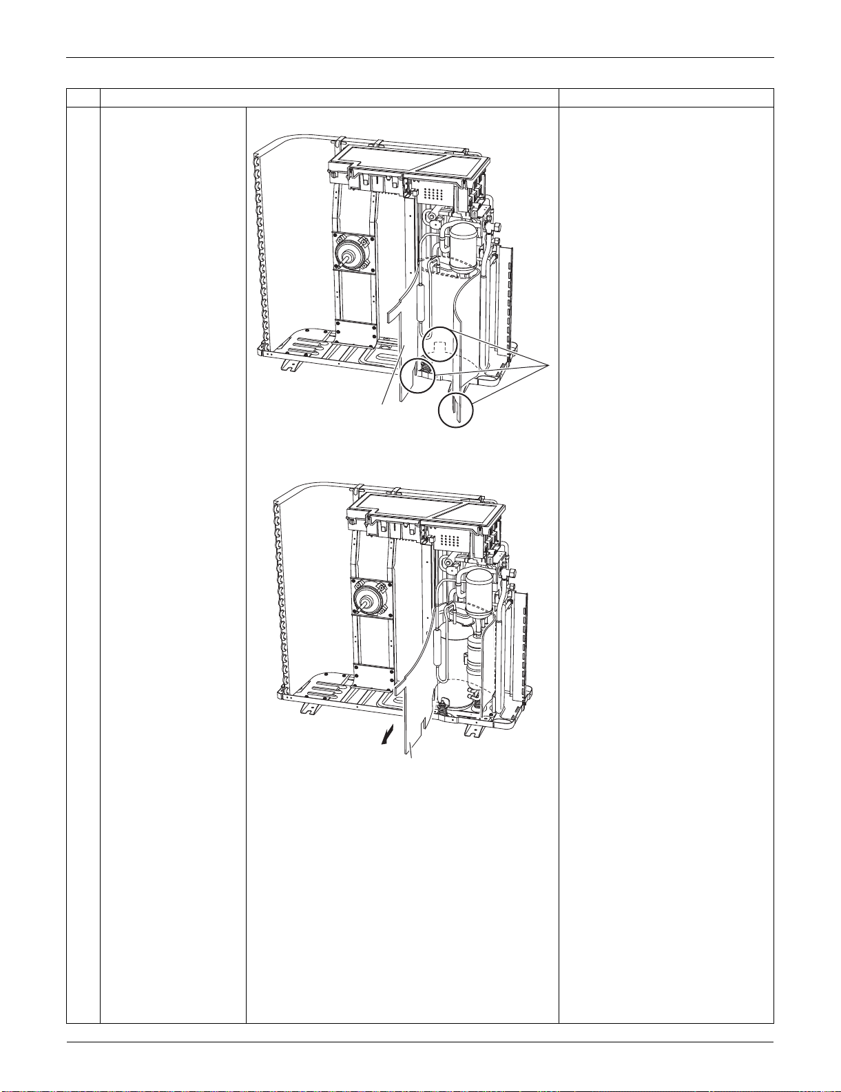
Outdoor Unit: RXS24LVJU SiUS091133
353 Removal Procedure
6
Open the sound blanket
(inner).
The sound blanket is fragile. Be
careful of the notches of the
compressor mount (3 locations).
7
Remove the sound
blanket (inner).
Step
Procedure Points
Sound blanket (inner)
(R7018)
Sound blanket
(inner)
(R7019)
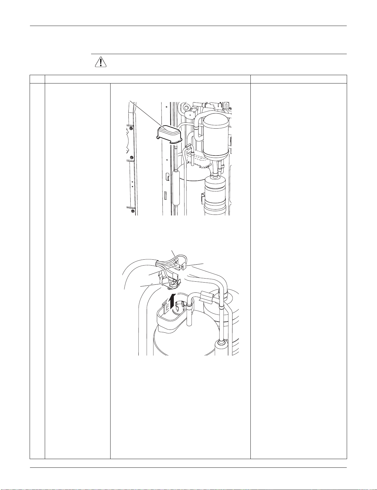
SiUS091133 Outdoor Unit: RXS24LVJU
Removal Procedure 354
6.7 Removal of Compressor
Procedure Warning Be sure to wait for 10 minutes or more after turning off all power supplies
before disassembling work.
Step
Procedure Points
1
Remove the terminal
cover.
2
Pull out the 3 lead
wires.
3
Remove the overload
protector (OL).
Terminal cover
(R9690)
W (blue)
U (red)
V (yellow)
OL
(R9471)
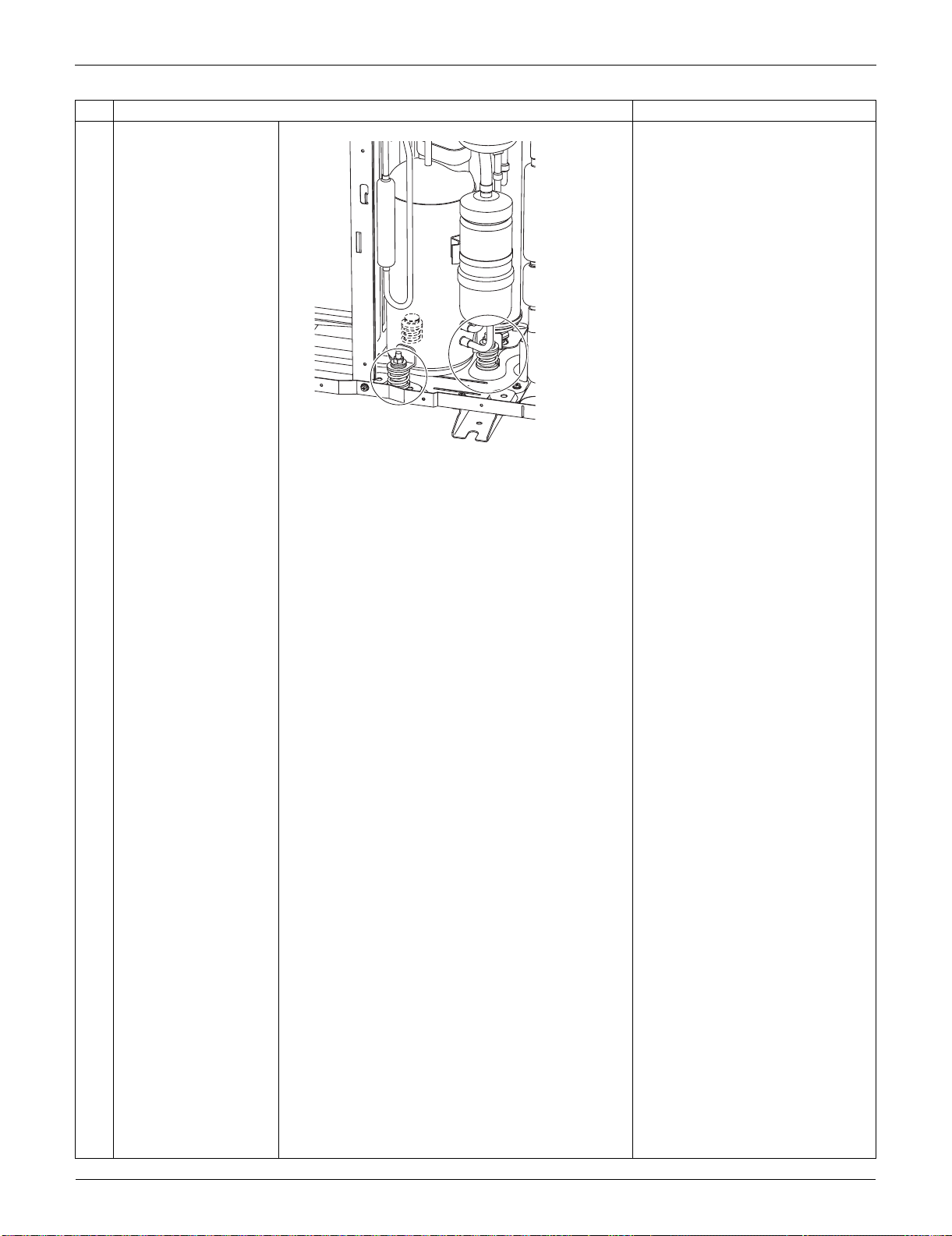
Outdoor Unit: RXS24LVJU SiUS091133
355 Removal Procedure
4
Remove the 2 nuts. Disconnect the piping, referring
to page 381.
Step
Procedure Points
(R9472)
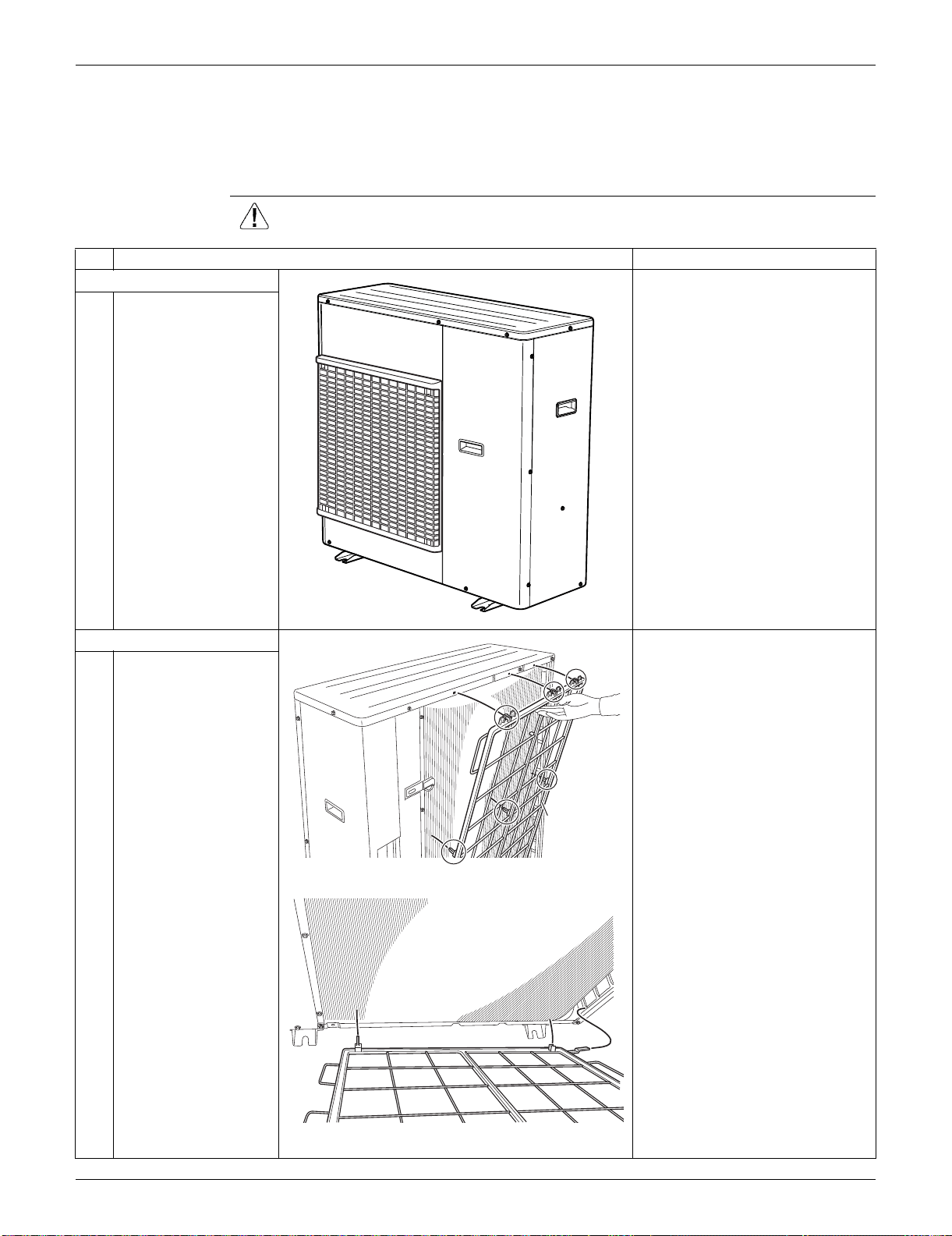
SiUS091133 Outdoor Unit: RKS30/36LVJU, RXS30/36LVJU
Removal Procedure 356
7. Outdoor Unit: RKS30/36LVJU, RXS30/36LVJU
Note: The illustrations are for heat pump models as representative.
7.1 Removal of Outer Panels
Procedure Warning Be sure to wait for 10 minutes or more after turning off all power supplies
before disassembling work.
Step
Procedure Points
1. Appearance features.
2. Remove the suction grille. The hooks are secured in the
clearances of the outdoor heat
exchanger fins.
1
Unfasten the 3 hooks at
the upper first, and then
3 hooks at the middle.
2
Unfasten the 3 hooks at
the bottom and remove
the suction grille.
(R16618)
(R16619)
Suction grille
(R9587)
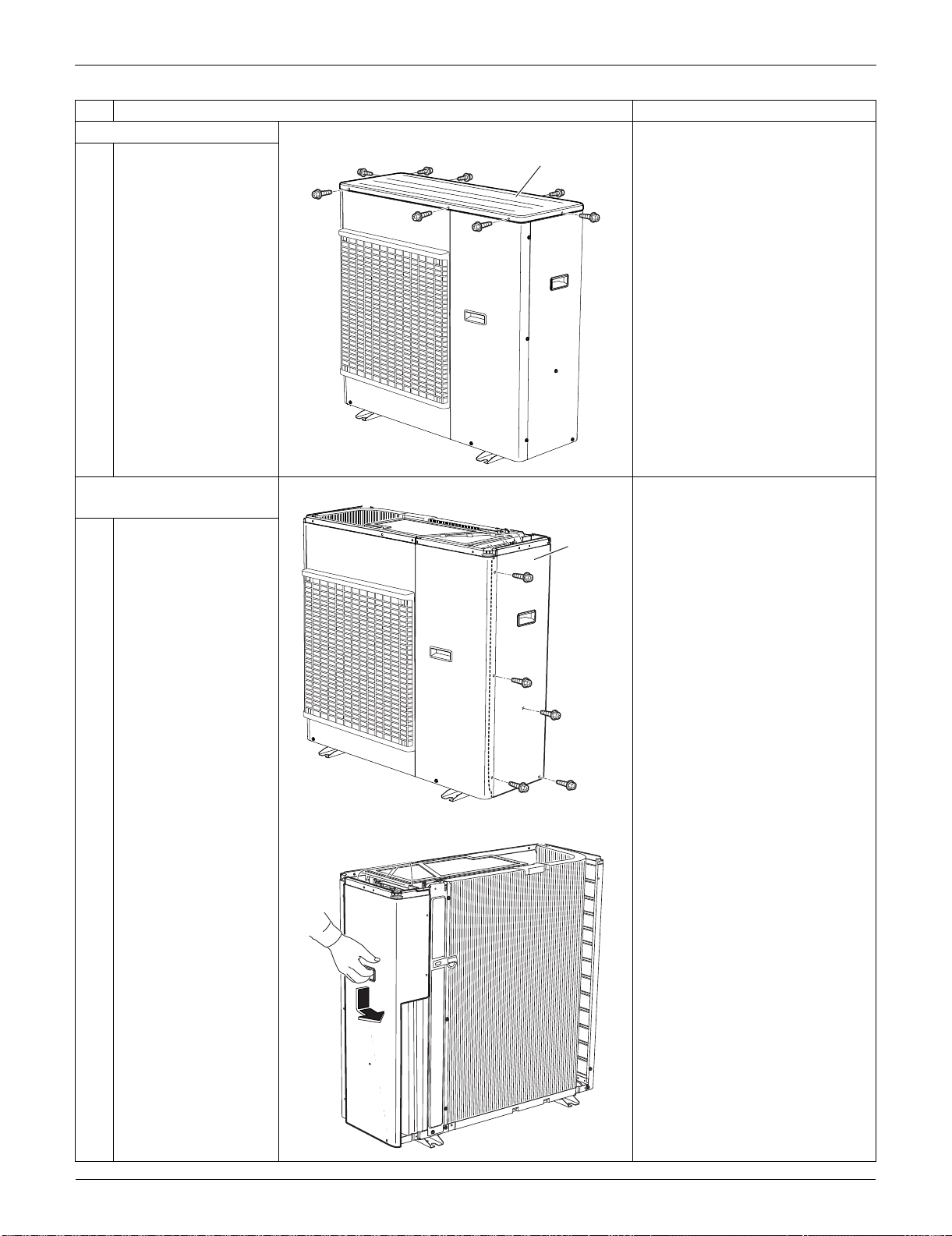
Outdoor Unit: RKS30/36LVJU, RXS30/36LVJU SiUS091133
357 Removal Procedure
3. Remove the top panel.
1
Remove the 9 screws
and remove the top
panel.
4. Remove the right side
panel.
1
Remove the 5 screws.
2
Slide the right side
panel downward to
unfasten the 2 hooks on
the back side.
Step
Procedure Points
(R16620)
Top panel
(R16621)
Right
side
panel
(R9688)
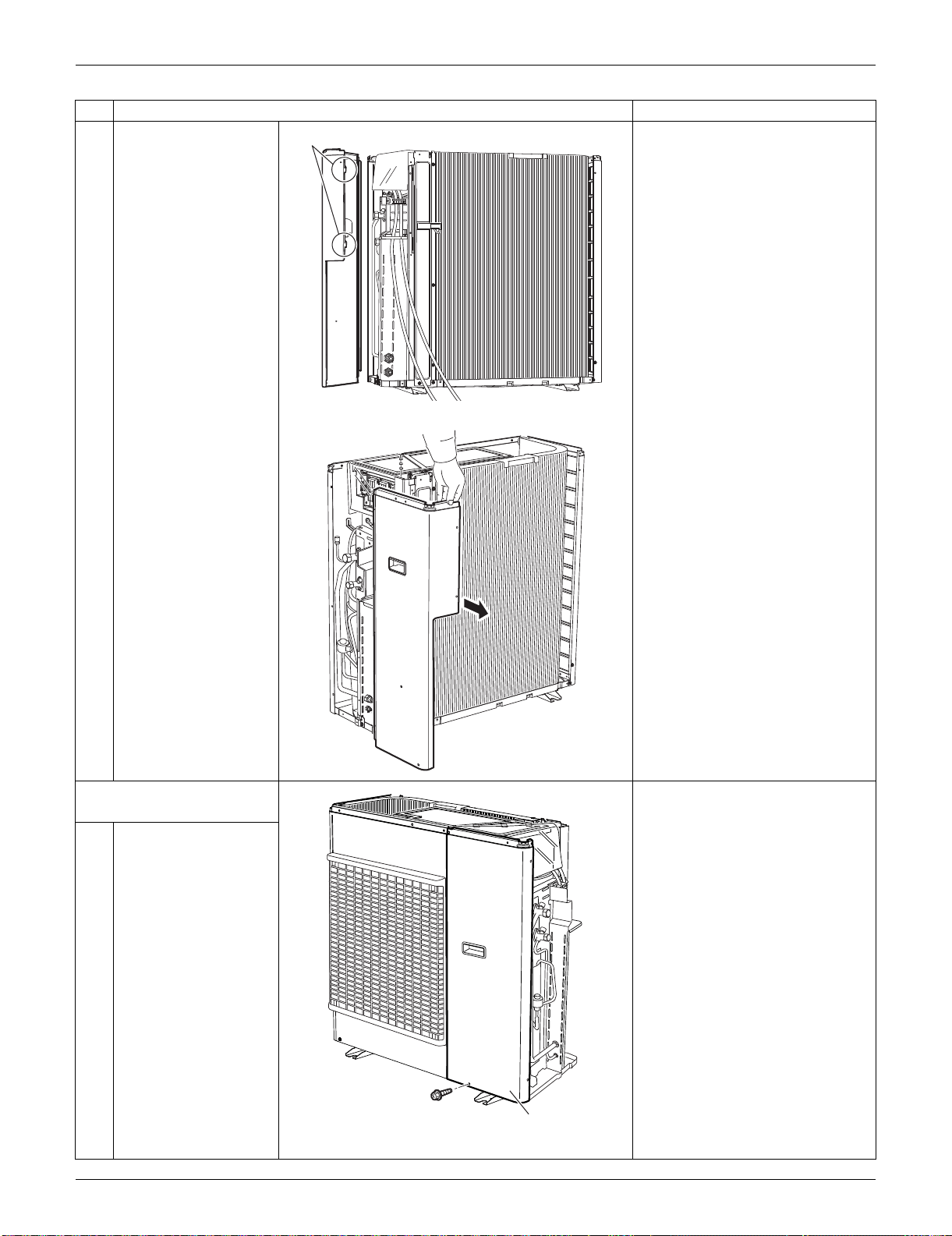
SiUS091133 Outdoor Unit: RKS30/36LVJU, RXS30/36LVJU
Removal Procedure 358
3
Remove the right side
panel.
5. Remove the front panel
(2).
1
Remove the screw.
Step
Procedure Points
Hook
(R16622)
(R16623)
(R16624)
Front panel (2)
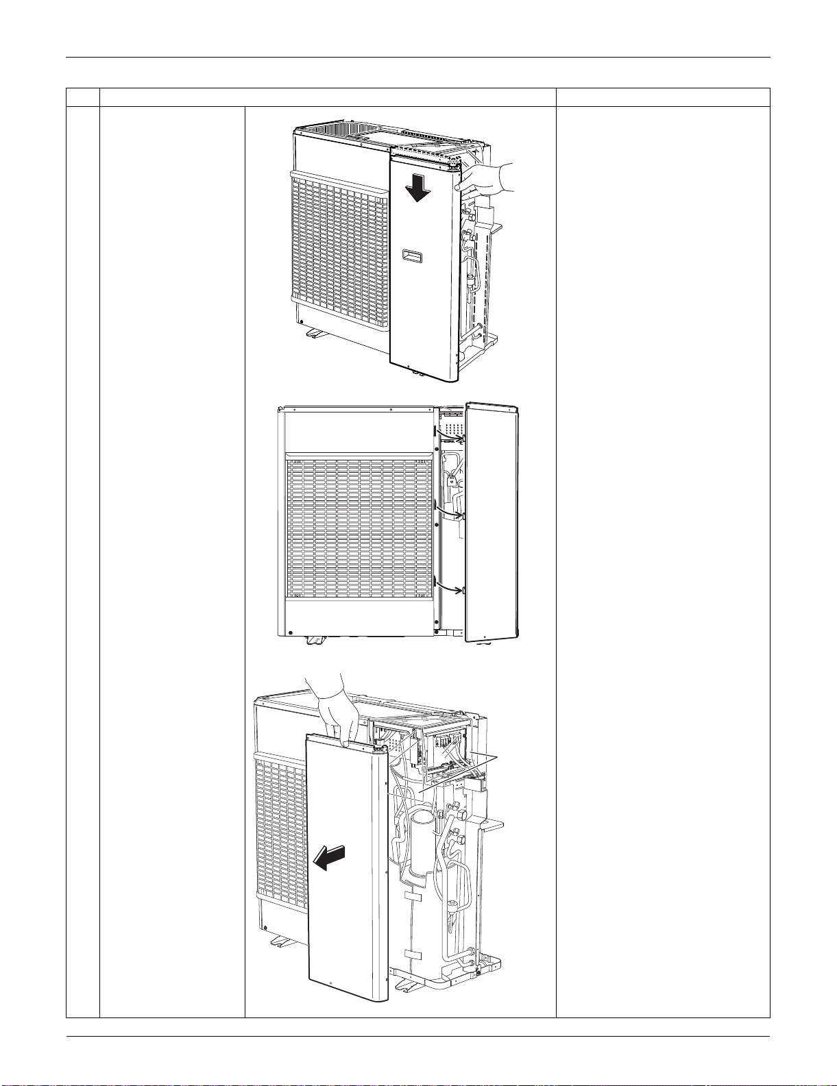
Outdoor Unit: RKS30/36LVJU, RXS30/36LVJU SiUS091133
359 Removal Procedure
2
Slide the front panel (2)
downward to unfasten
the 3 hooks.
3
Remove the front panel
(2).
The insulation sheet is inserted
between the front panel (2) and
the electrical box.
Step
Procedure Points
(R16625)
(R16626)
(R16627)
Insulation
sheet
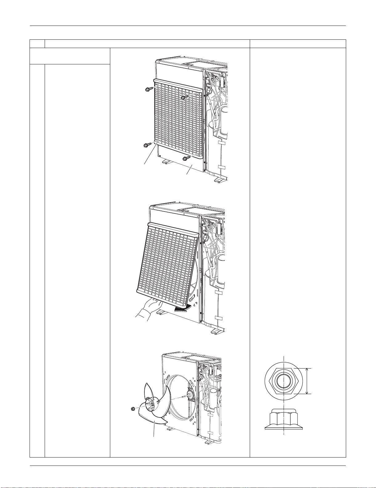
SiUS091133 Outdoor Unit: RKS30/36LVJU, RXS30/36LVJU
Removal Procedure 360
6. Remove the front panel
(1).
Remove the discharge grille and
the outdoor fan first to remove
the front panel (1).
1
Remove the 4 screws
on the discharge grille.
2
Pull the bottom of the
discharge grille and
remove it.
3
Remove the outdoor
fan fixing nut.
Nut size: M8
Step
Procedure Points
(R9757)
Discharge grille
Front panel (1)
(R9758)
(R16628)
Outdoor fan
13 mm
(0.51 inch)
(R17005)
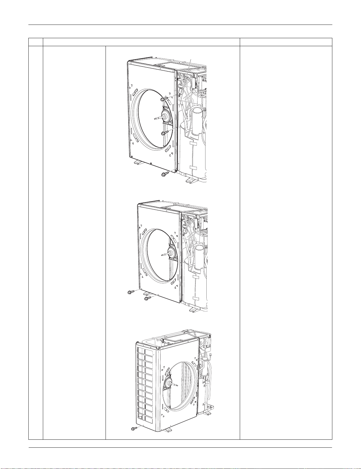
Outdoor Unit: RKS30/36LVJU, RXS30/36LVJU SiUS091133
361 Removal Procedure
4
Remove the 3 screws
on the partition plate
(1).
5
Remove the 2 screws
at the bottom of the
front.
6
Remove the screw at
the bottom of the left
side.
Step
Procedure Points
Partition plate (1)
(R16629)
(R16630)
(R9601)
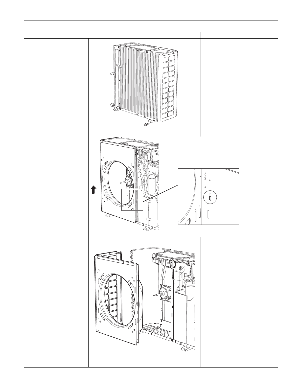
SiUS091133 Outdoor Unit: RKS30/36LVJU, RXS30/36LVJU
Removal Procedure 362
7
Remove the screw at
the bottom of the back
side.
8
The front panel (1) has
a hook on its front. Lift
the front panel (1).
9
Remove the front panel
(1).
Step
Procedure Points
(R9602)
Hook
(R16631)
(R9604)
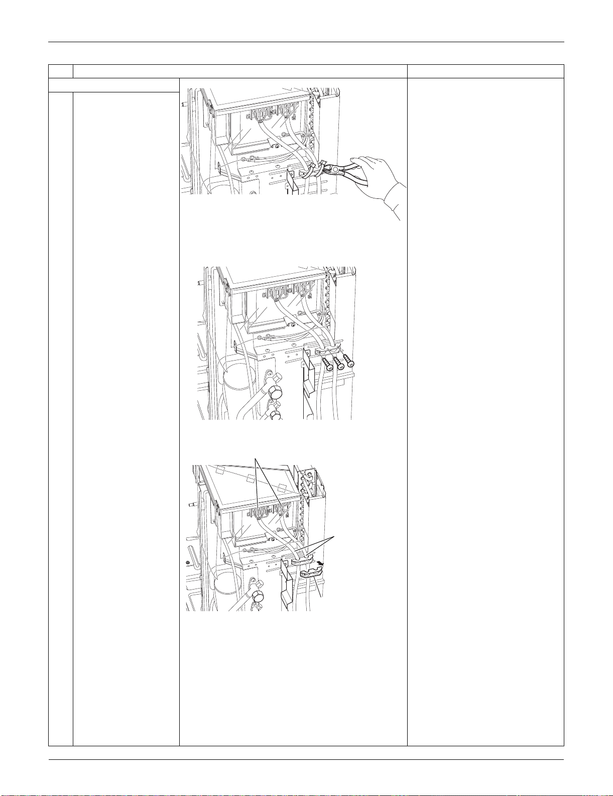
Outdoor Unit: RKS30/36LVJU, RXS30/36LVJU SiUS091133
363 Removal Procedure
7. Remove the rear panel.
1
Cut the clamp.
2
Remove the 3 screws.
3
4
Remove the wire fixing
plate.
Remove the 7 screws
of the terminal board
and ground wires.
Detach the connection
wires and the power
supply wires.
Step
Procedure Points
(R17015)
(R17016)
Wire fixing plate
(R17017)
Connecting wires
Terminal board
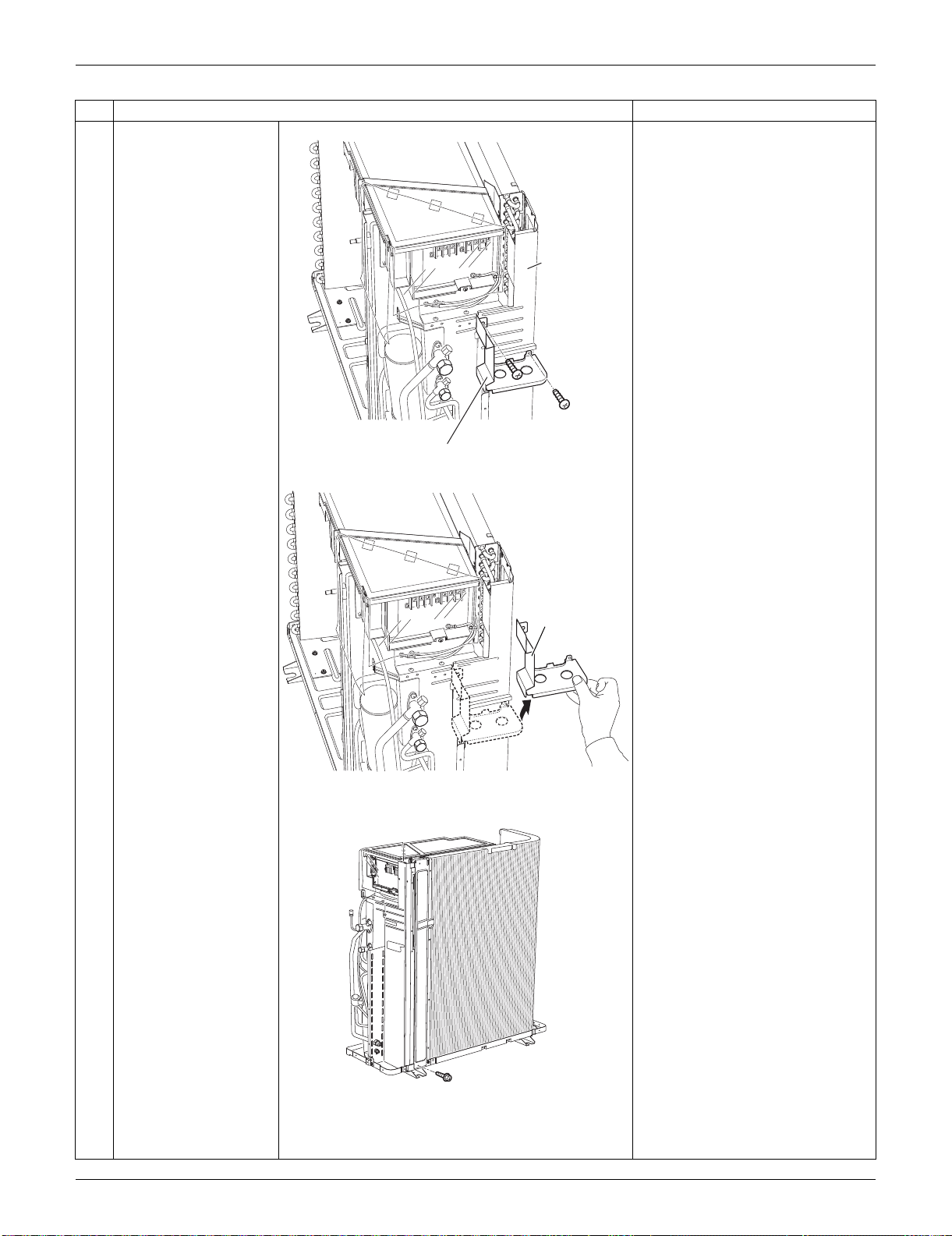
SiUS091133 Outdoor Unit: RKS30/36LVJU, RXS30/36LVJU
Removal Procedure 364
5
Remove the 2 screws
on the partition plate
(2).
6
Lift up slightly and
remove the partition
plate (2).
7
Remove the screw on
the bottom frame.
Step
Procedure Points
(R17013)
Partition plate (2)
Rear panel
(R17014)
Partition plate (2)
(R16637)
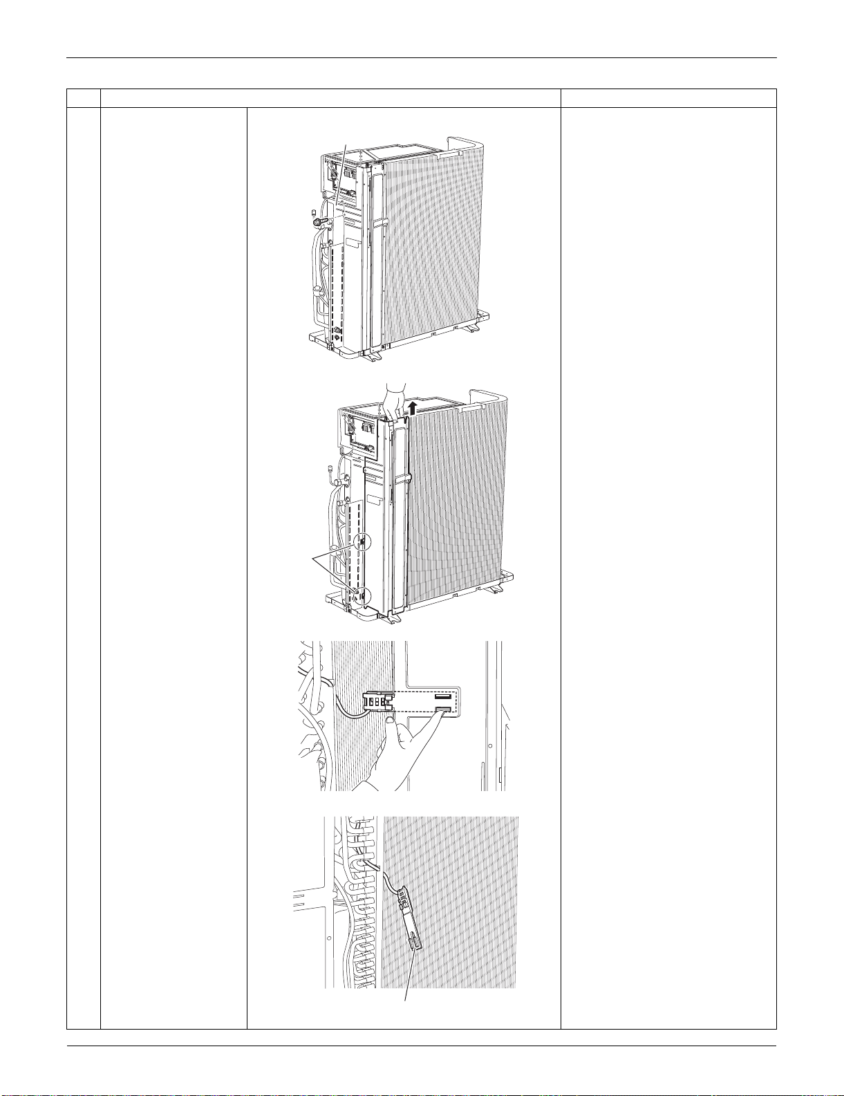
Outdoor Unit: RKS30/36LVJU, RXS30/36LVJU SiUS091133
365 Removal Procedure
8
Remove the screw on
the stop valve mounting
plate.
9
Lift the rear panel
upward to unfasten the
2 hooks.
10
Push the hooks of the
outdoor temperature
thermistor holder from
inner-side of the rear
panel and detach it.
Step
Procedure Points
Stop valve
mounting plate
(R16638)
(R16639)
Hook
(R9615)
Outdoor temperature thermistor holder
(R9616)
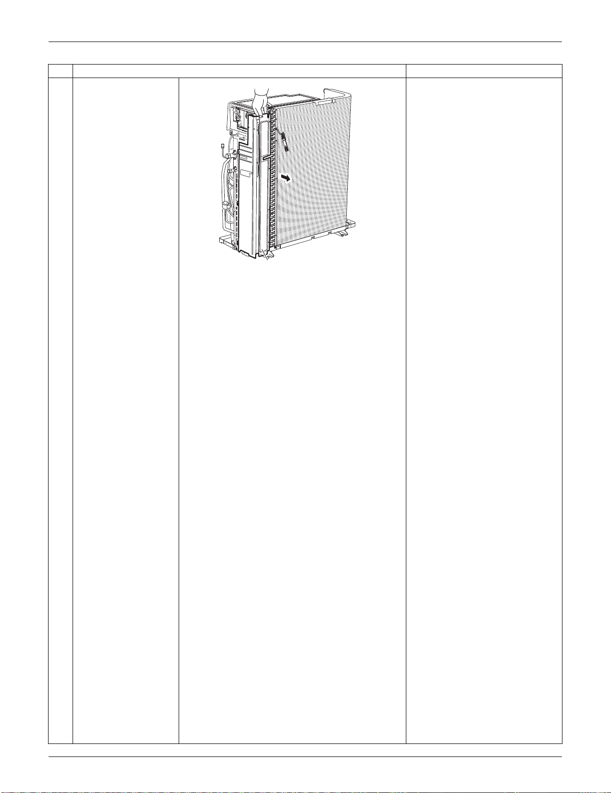
SiUS091133 Outdoor Unit: RKS30/36LVJU, RXS30/36LVJU
Removal Procedure 366
11
Remove the rear panel.
Step
Procedure Points
Rear panel
(R16640)
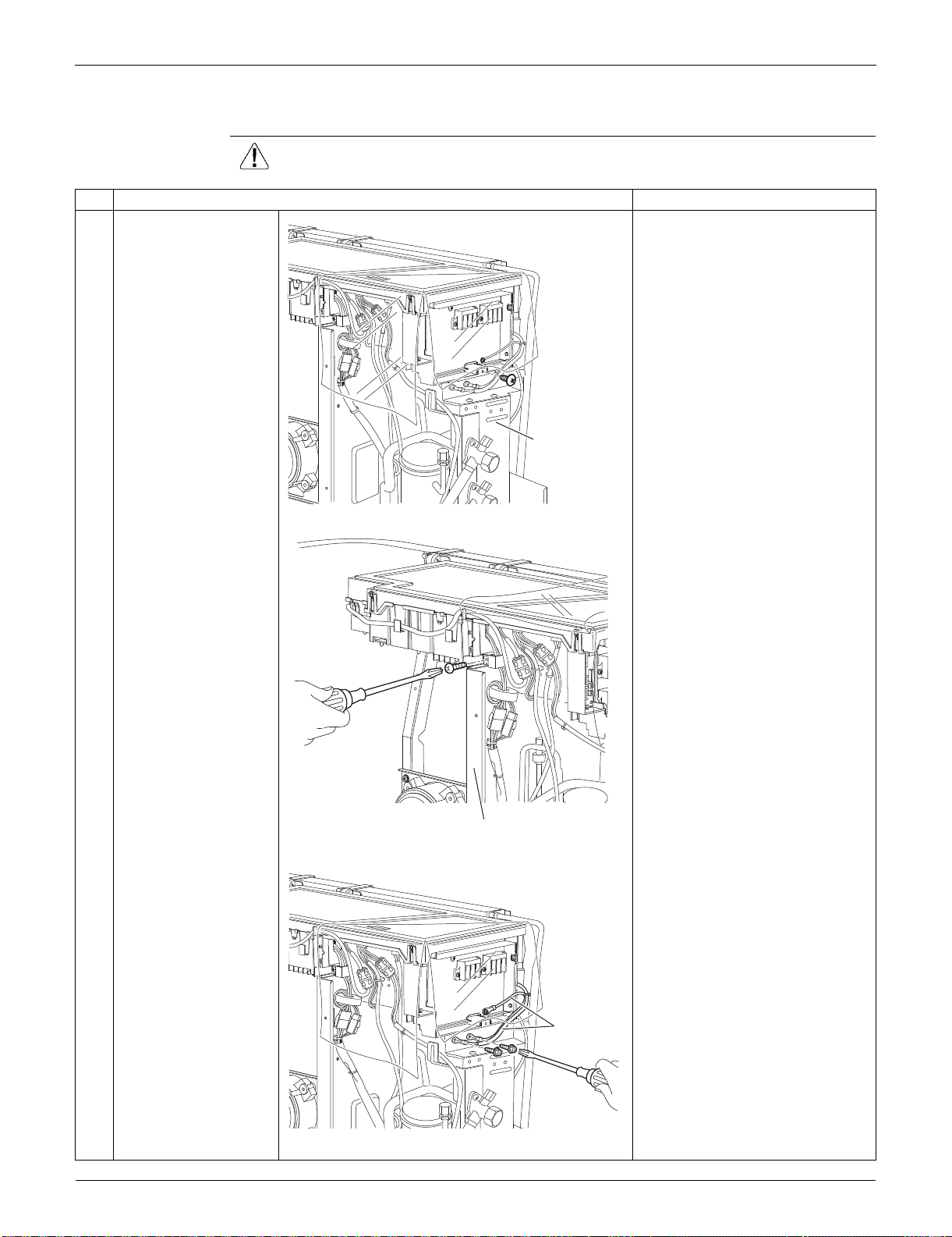
Outdoor Unit: RKS30/36LVJU, RXS30/36LVJU SiUS091133
367 Removal Procedure
7.2 Removal of Electrical Box
Procedure Warning Be sure to wait for 10 minutes or more after turning off all power supplies
before disassembling work.
Step
Procedure Points
1 Remove the screw on
the stop valve mounting
plate.
2 Remove the screw on
the partition plate (1).
3 Remove the 2 screws
to detach the ground
wires.
Stop valve
mounting plate
(R16641)
Partition plate (1)
(R16917)
Ground wire
(R16642)
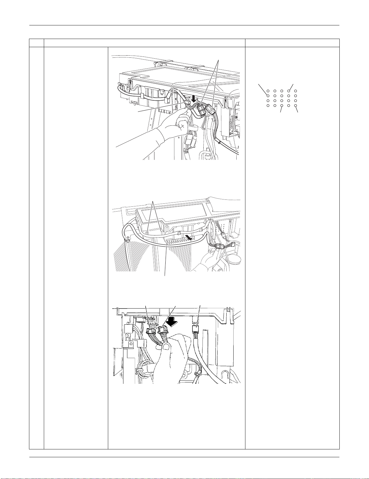
SiUS091133 Outdoor Unit: RKS30/36LVJU, RXS30/36LVJU
Removal Procedure 368
4
Disconnect the
connector for fan motor
[S70] and release the 4
clamps attached to the
electrical box.
When reassembling, insert each
clamp into the small hole.
5
Release the fan motor
lead wire.
: When reassembling, do not use
these 2 hooks.
6
Disconnect the
connectors of the front
side.
[S20]: electronic expansion valve
coil
[S80]: four-way valve coil
[S90]: thermistors
Cooling only models have no
harness for [S80].
Step
Procedure Points
[S70]
Ferrite core
(R16918)
For the ferrite core
of electronic
expansion valve coil
For the thermistor
ASSY harnesses
For the four way
valve coil harness
For the ferrite
core of fan
motor
(R16919)
(R14466)
Fan motor lead wire
[S20] [S90] [S80]
(R9622)
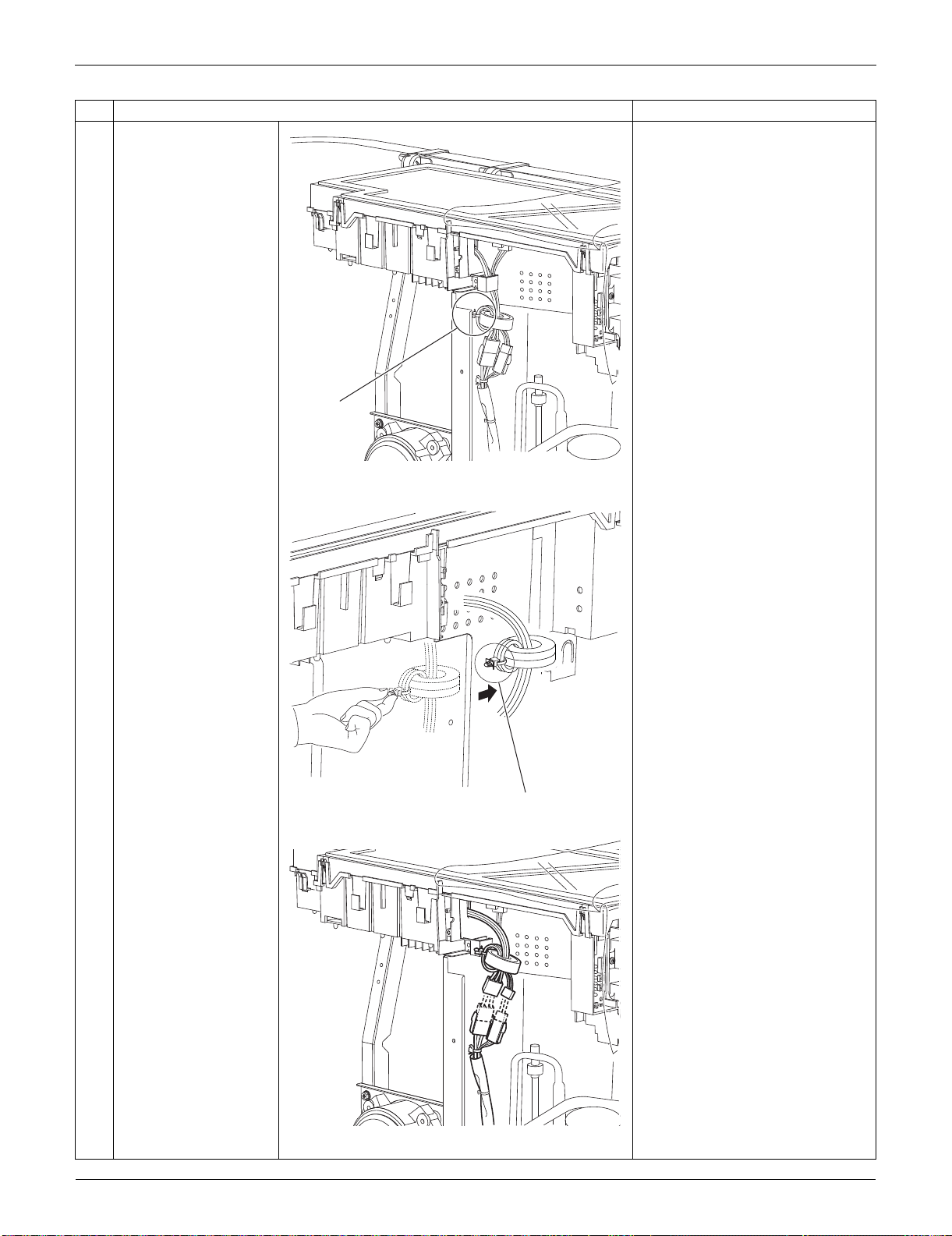
Outdoor Unit: RKS30/36LVJU, RXS30/36LVJU SiUS091133
369 Removal Procedure
7 The compressor lead
wire is fixed on the
partition plate (1) with a
clamp.
8 Pull out the clamp and
release the compressor
lead wire.
9 Disconnect the relay
connector for the
overload protector and
the compressor.
Step
Procedure Points
(R9623)
Clamp
(R9624)
Clamp
(R9625)
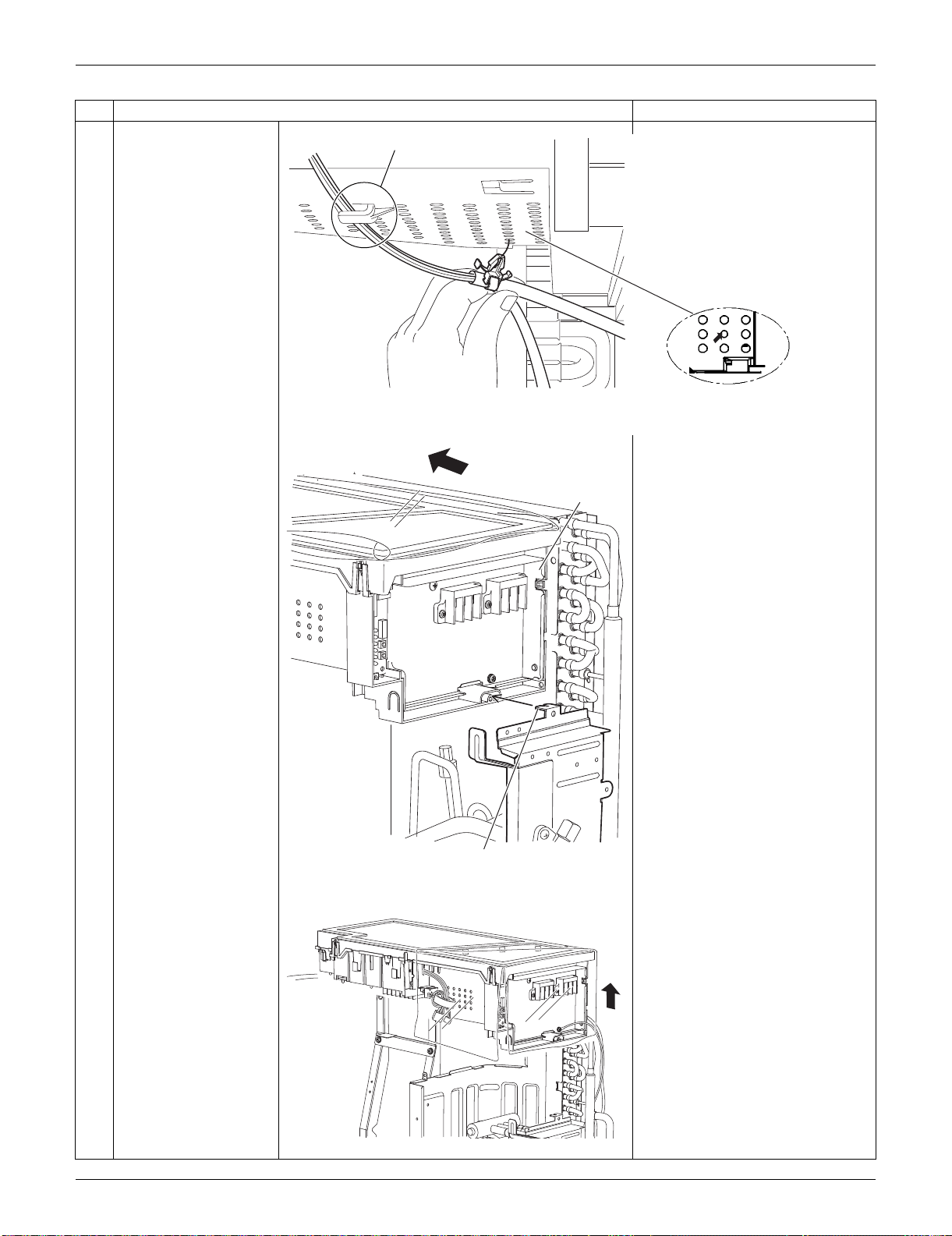
SiUS091133 Outdoor Unit: RKS30/36LVJU, RXS30/36LVJU
Removal Procedure 370
10 Release the thermistor
harness from the hook
at the bottom of
electrical box.
11 Pull out the clamp of
the thermistor harness
from the hole of the
electrical box.
12 Slide the electrical box
leftward to unfasten the
hook on the right side of
the box.
13 Lift up the electrical box
and remove it.
Step
Procedure Points
Fixing position for the
thermistor harness
Hook
(R16647)
When reassembling, insert
the clamp into the small hole.
Electrical box
Hook
(R16643)
(R16644)
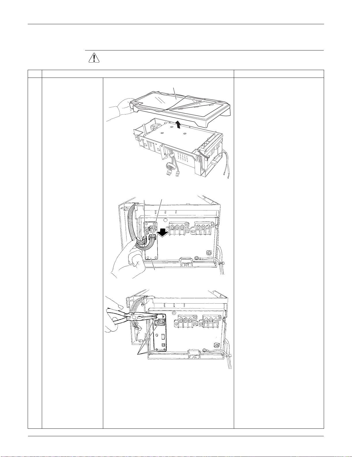
Outdoor Unit: RKS30/36LVJU, RXS30/36LVJU SiUS091133
371 Removal Procedure
7.3 Removal of PCBs
Procedure Warning Be sure to wait for 10 minutes or more after turning off all power supplies
before disassembling work.
Step
Procedure Points
1
Remove the cover. Preparation
Remove the electrical box
according to the “Removal of
Electrical Box”.
2
Disconnect the
connectors [S52]
[S102] from the service
monitor PCB.
3
Detach the 4 clamps
with pliers and remove
the service monitor
PCB.
Cover
(R9611)
Service monitor PCB
[S52]
[S102]
(R16707)
Clamp
(R16708)
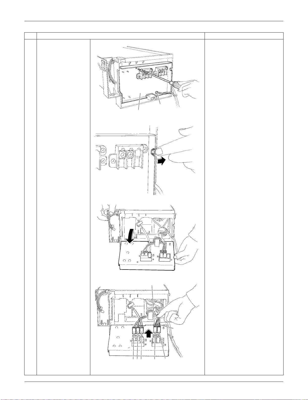
SiUS091133 Outdoor Unit: RKS30/36LVJU, RXS30/36LVJU
Removal Procedure 372
4
Remove the screws of
the terminal board and
the ground wire.
5
Unfasten the hook on
the right.
6
Open the terminal
board.
7
Disconnect the
harnesses.
1: Black
2: White
3: Red
L1: Black
L2: Brown
N1: White
N2: Blue
Step
Procedure Points
Terminal board
(R16709)
Ground wire
(R5283)
(R5284)
L2
N2
1
2
3
L1
N1
(R5285)
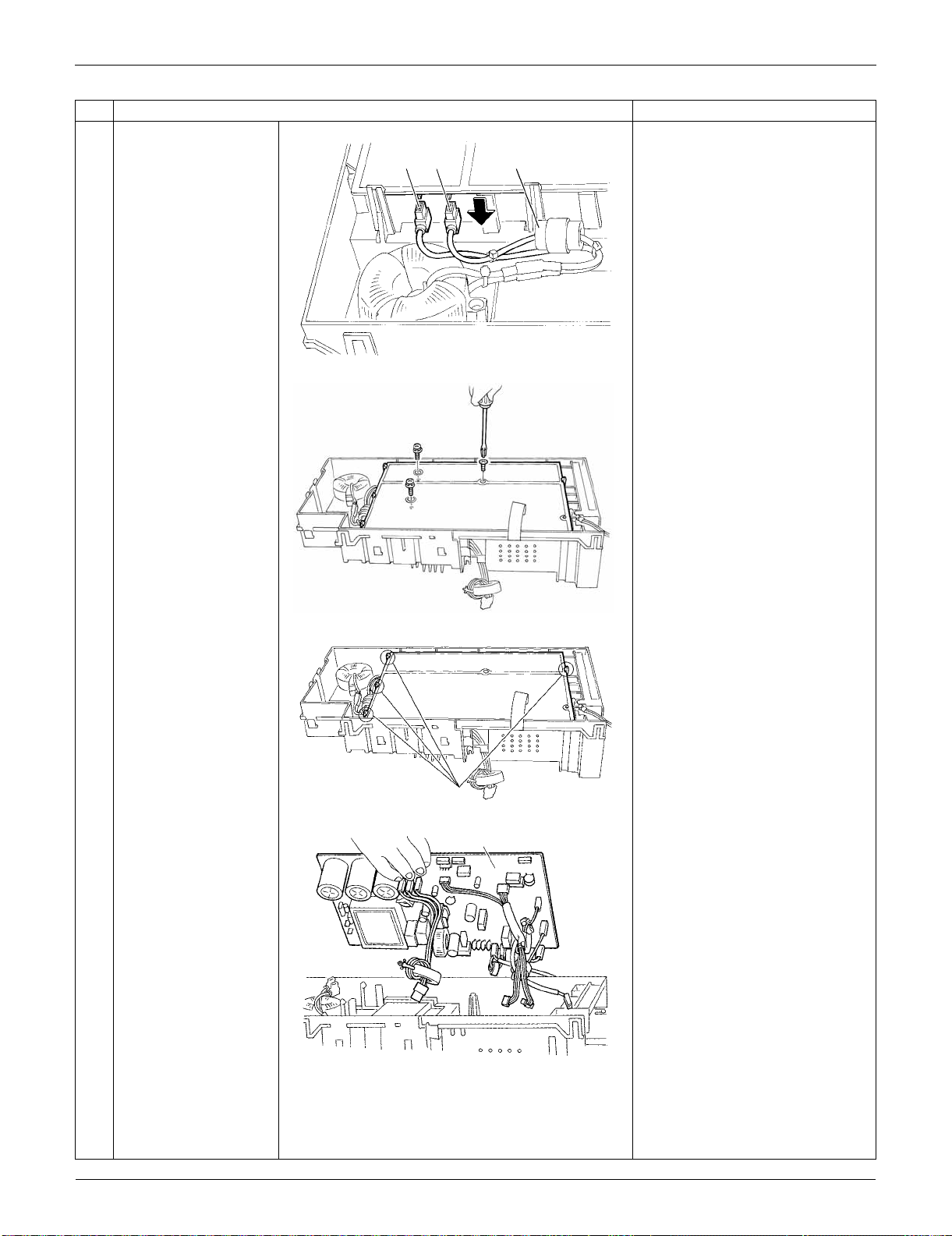
Outdoor Unit: RKS30/36LVJU, RXS30/36LVJU SiUS091133
373 Removal Procedure
8
Disconnect the 2
harnesses for the
reactor [HR1] [HR2].
[HR1] : white
[HR2] : blue
The harness for [HR2] has a
ferrite core.
9
Remove the 3 screws
of the main PCB.
10
Release the 4 hooks.
11
Lift up and remove the
main PCB.
Refer to page 26 for detail.
Step
Procedure Points
[HR1][HR2] Ferrite core
(R5286)
(R5287)
Hook
(R13524)
(R5289)
Main PCB
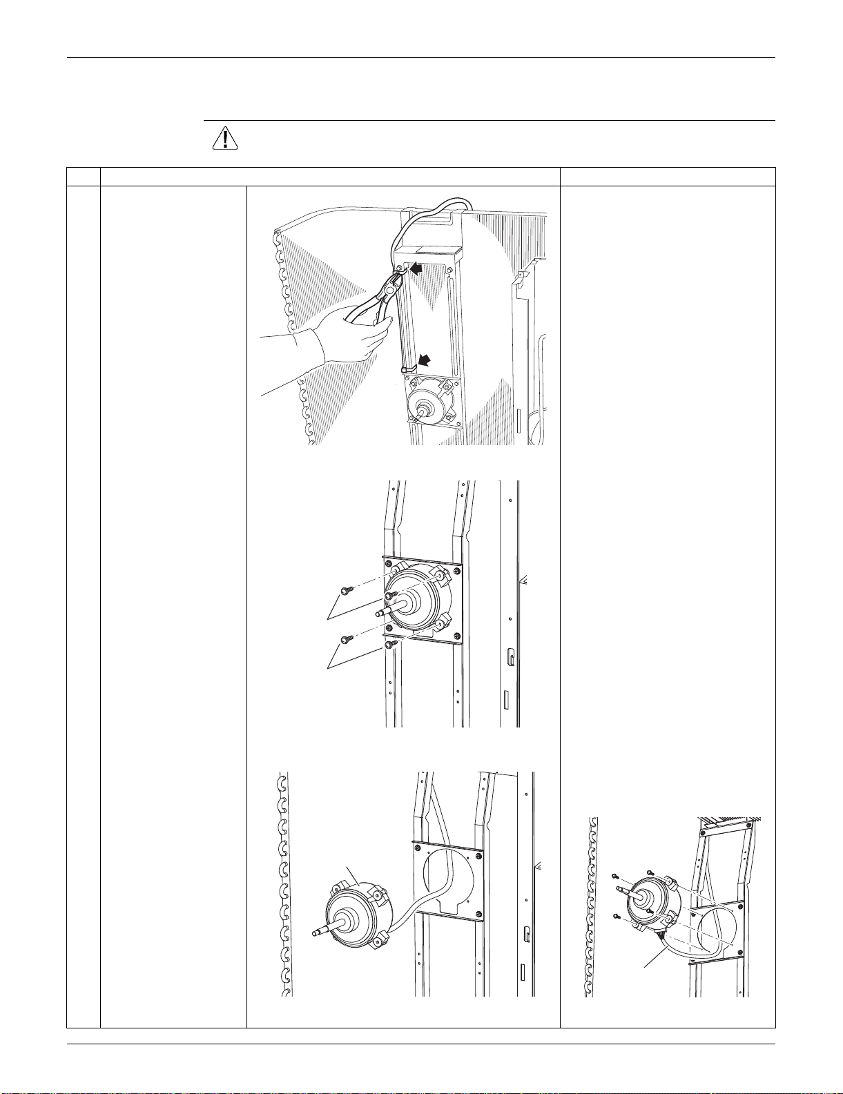
SiUS091133 Outdoor Unit: RKS30/36LVJU, RXS30/36LVJU
Removal Procedure 374
7.4 Removal of Fan Motor
Procedure Warning Be sure to wait for 10 minutes or more after turning off all power supplies
before disassembling work.
Step
Procedure Points
1 Cut the clamps at 2
locations.
Preparation
Remove the electrical box
according to the "Removal of
Electrical Box".
2
3
Remove the 2 lower
screws first.
Then, remove the 2
upper screws.
Be sure to remove the lower
screws first. If the top screws
are removed first, the fan motor
may tilt down or fall and cause
injury because its center of
gravity is shifted to the front.
4 Remove the fan motor. When reassembling, make sure
that the wire harness is facing
downward.
(R9630)
2
1
(R6442)
Fan motor
(R6443)
Harness
(R6444)
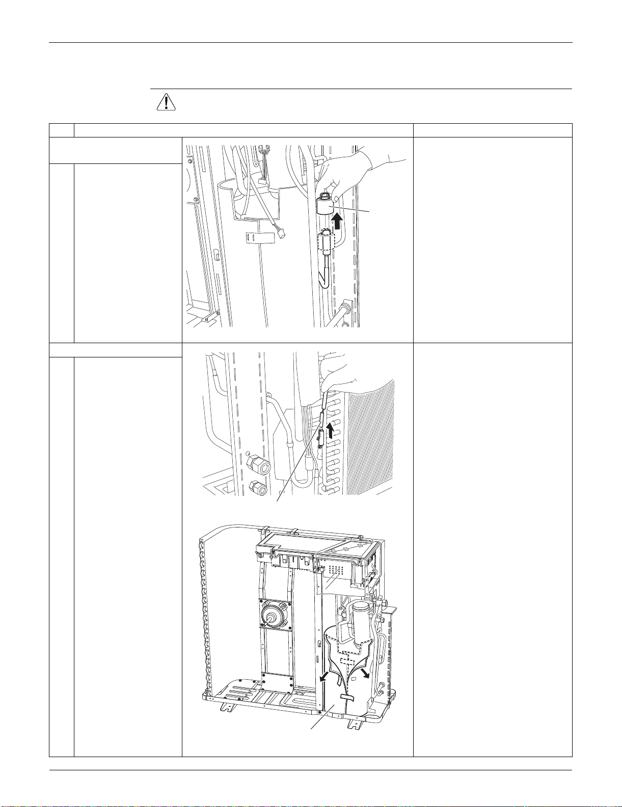
Outdoor Unit: RKS30/36LVJU, RXS30/36LVJU SiUS091133
375 Removal Procedure
7.5 Removal of Coils / Thermistors
Procedure Warning Be sure to wait for 10 minutes or more after turning off all power supplies
before disassembling work.
Step
Procedure Points
1. Remove the electronic
expansion valve coil.
1 Pull the electronic
expansion valve coil
out.
2. Remove the thermistors. You can remove the thermistor
ASSY with the electrical box on.
(1) Disconnect [S90] from the
electrical box (main PCB).
(2) Release the thermistor harness
from the hook at the bottom of
electrical box.
(3) Pull out the clamp of the
thermistor harness from the hole
of the electrical box.
1
Pull out the outdoor
heat exchanger
thermistor.
2
Slightly open the sound
blanket (outer).
Electronic
expansion
valve coil
(R9631)
Outdoor heat exchanger thermistor
(R9632)
Sound blanket (outer)
(R9633)
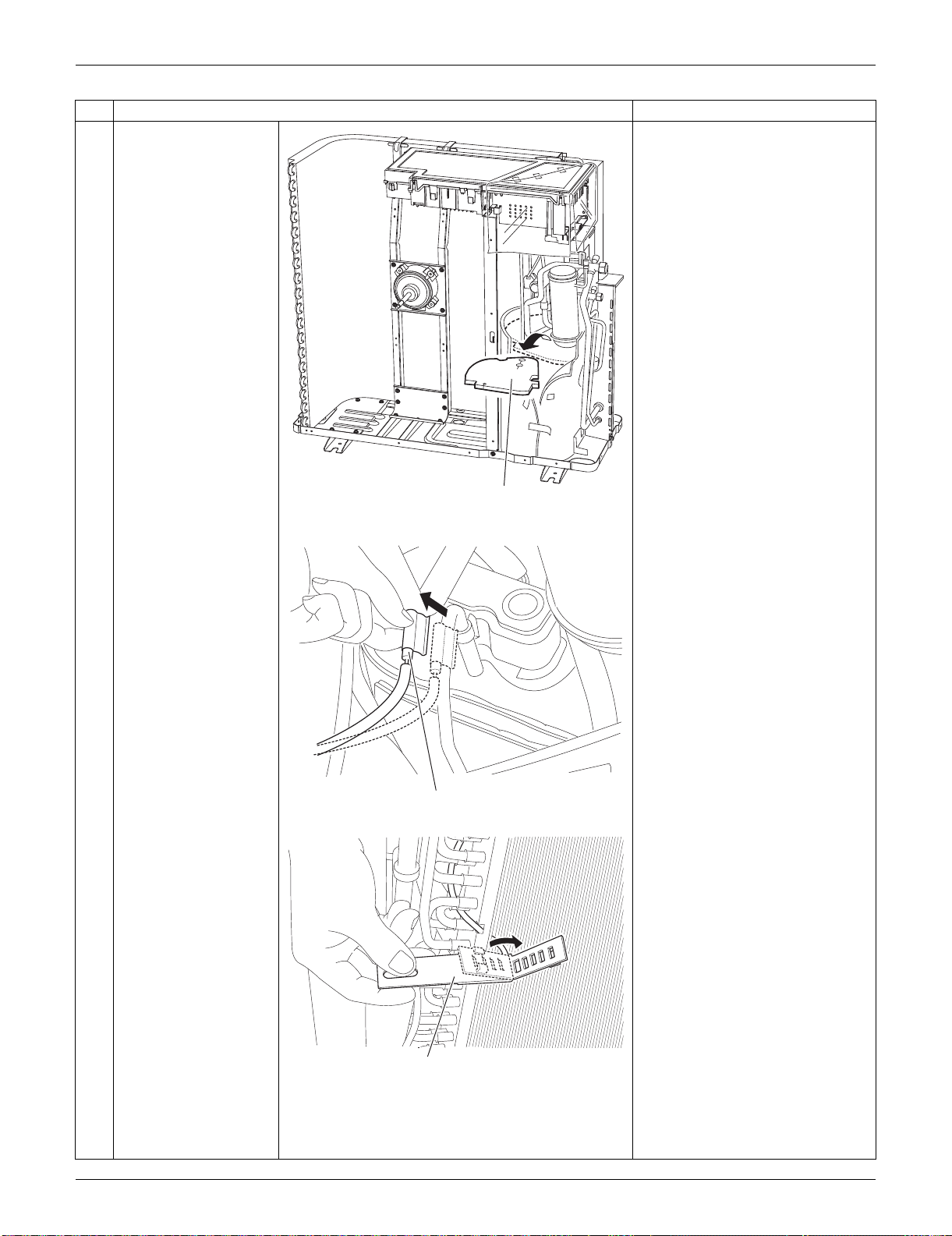
SiUS091133 Outdoor Unit: RKS30/36LVJU, RXS30/36LVJU
Removal Procedure 376
3
Remove the sound
blanket (top upper).
4
Remove the discharge
pipe thermistor.
5
At the back side, open
the outdoor
temperature thermistor
holder.
Step
Procedure Points
Sound blanket
(top upper)
(R16920)
(R9635)
Discharge pipe thermistor
Outdoor temperature thermistor holder
(R9636)
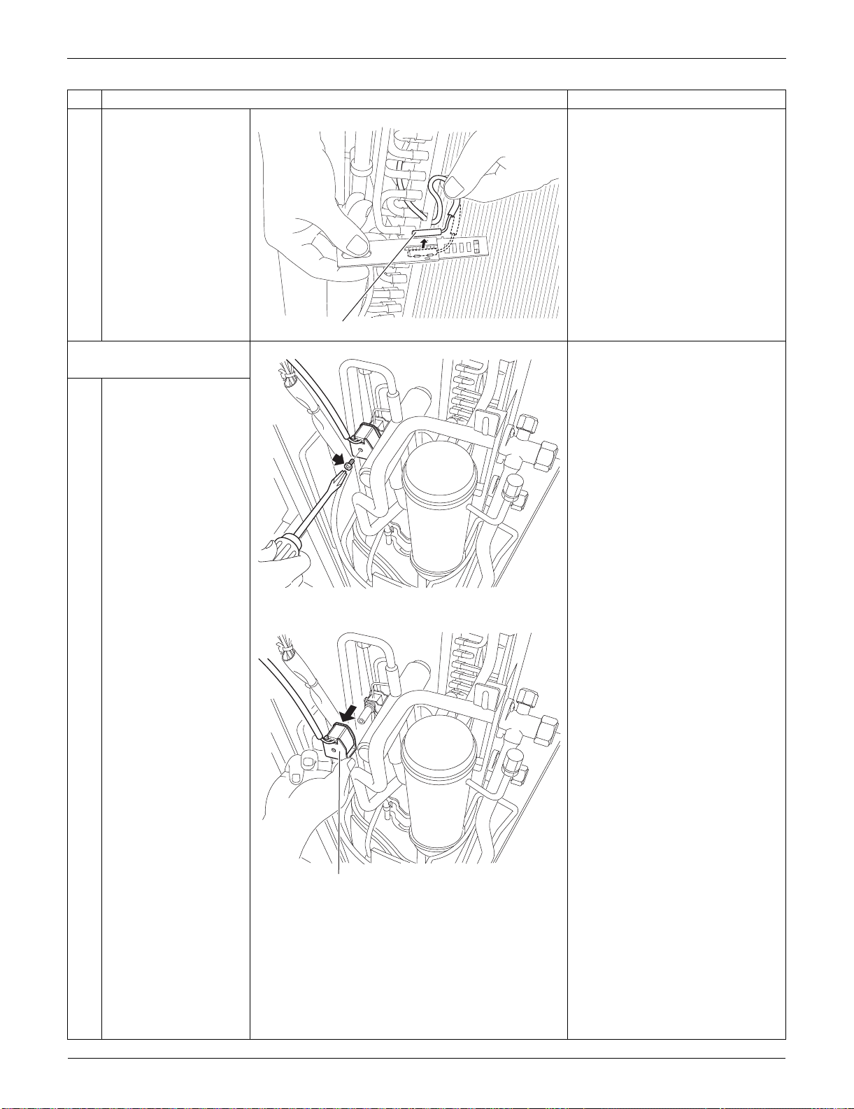
Outdoor Unit: RKS30/36LVJU, RXS30/36LVJU SiUS091133
377 Removal Procedure
6
Release the outdoor
temperature thermistor.
3. Remove the four-way
valve coil.
1
Remove the screw.
2
Remove the four-way
valve coil.
Step
Procedure Points
Outdoor temperature thermistor
(R9637)
(R9638)
Four way valve coil
(R9639)
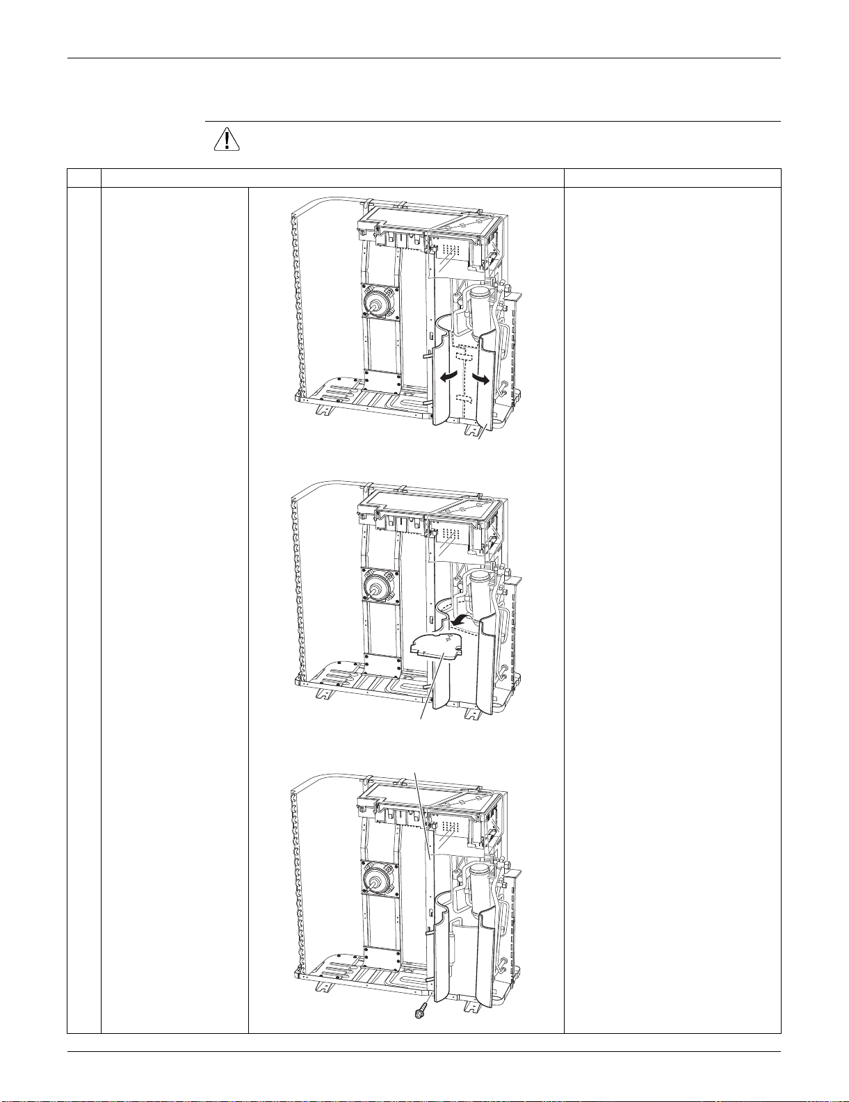
SiUS091133 Outdoor Unit: RKS30/36LVJU, RXS30/36LVJU
Removal Procedure 378
7.6 Removal of Sound Blankets
Procedure Warning Be sure to wait for 10 minutes or more after turning off all power supplies
before disassembling work.
Step
Procedure Points
1
Open the sound blanket
(outer).
2
Remove the sound
blanket (top upper).
The sound blanket is fragile.
Carefully pass the discharge
pipe through it.
3
Remove the screw and
slightly push the
partition plate (1) to the
left for easy work.
(R16921)
Sound blanket
(outer)
Sound blanket
(top upper)
(R9641)
Partition plate (1)
(R9642)

Outdoor Unit: RKS30/36LVJU, RXS30/36LVJU SiUS091133
379 Removal Procedure
4
Remove the sound
blanket (outer).
5
Open the sound blanket
(inner).
6
Remove the sound
blanket (inner).
The sound blanket is fragile. Be
careful of the notches of the
compressor mount (4 locations).
Step
Procedure Points
Sound blanket
(outer)
(R9643)
Sound blanket
(inner)
Compressor mount
(R9644)
(R9645)
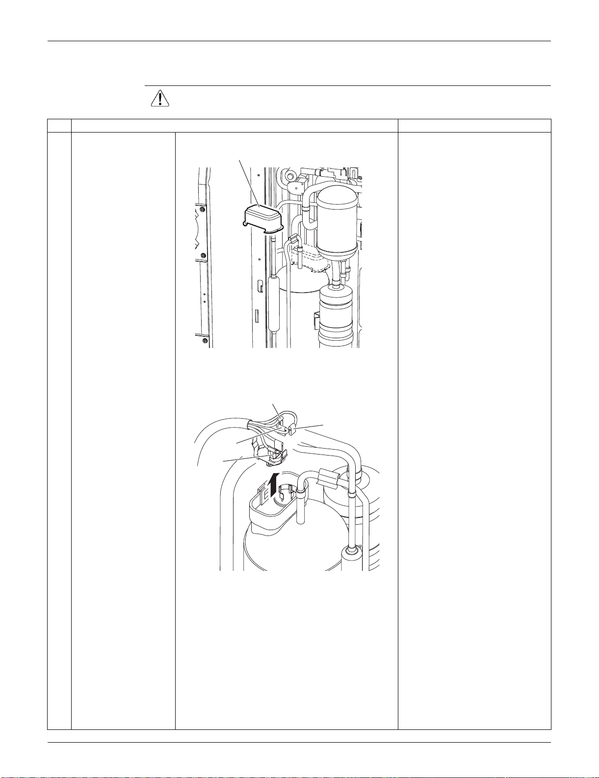
SiUS091133 Outdoor Unit: RKS30/36LVJU, RXS30/36LVJU
Removal Procedure 380
7.7 Removal of Compressor
Procedure Warning Be sure to wait for 10 minutes or more after turning off all power supplies
before disassembling work.
Step
Procedure Points
1
Remove the terminal
cover.
2
Pull out the 3 lead
wires.
U: red, V: yellow, W: blue
3
Remove the overload
protector (OL).
Terminal cover
(R9650)
W (blue)
U (red)
V (yellow)
OL
(R9471)
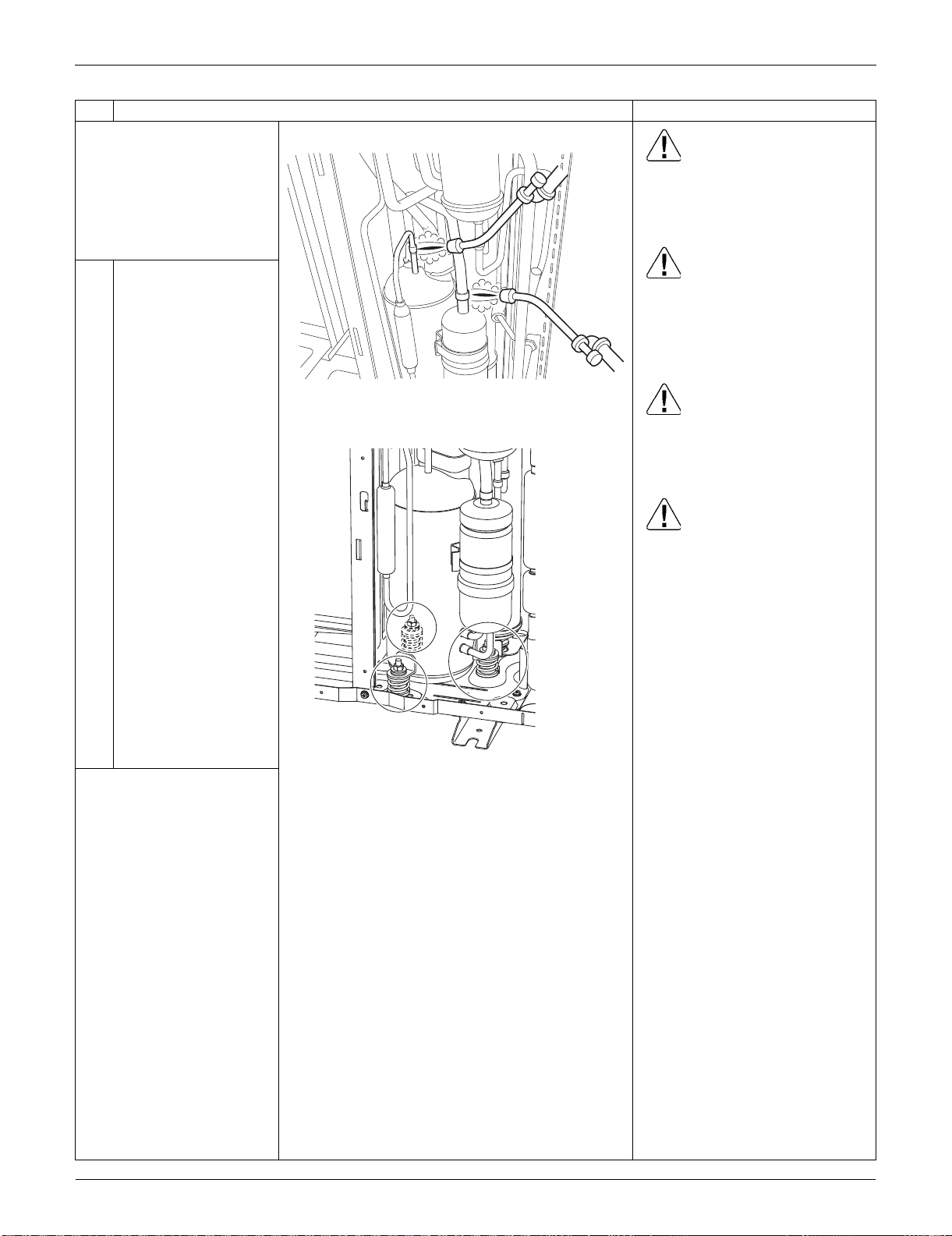
Outdoor Unit: RKS30/36LVJU, RXS30/36LVJU SiUS091133
381 Removal Procedure
Before working, make
sure that the refrigerant
gas is empty in the circuit.
Be sure to apply nitrogen
replacement when
heating up the brazed
part.
Warning
Use caution to avoid burning
yourself with pipes and other
parts that are heated by the gas
brazing machine.
Warning
If the refrigerant gas leaks during
work, immediately ventilate the
room. If refrigerant gas is
exposed to flames, toxic gas may
be generated.
Warning
If the refrigerant oil in the
compressor catches fire, have a
wet cloth prepared to extinguish
the fire immediately.
Caution
For global environmental
protection, do not discharge the
refrigerant gas in the
atmosphere. Make sure to collect
all the refrigerant gas.
Cautions for restoration
1. Restore the piping by non-
oxidation brazing.
2. It is required to prevent the
carbonization of the oil inside
the four-way valve and the
deterioration of the gaskets
affected by heat. Keep below
120°C (248°F). Wrap the four-
way valve with a wet cloth and
provide water so that the cloth
does not dry.
In case of difficulty with gas
brazing machine
1. Disconnect the brazed part
where is easy to disconnect and
restore.
2. Cut pipes on the main unit with
a tube cutter in order to make it
easy to disconnect.
4
Heat up the brazed part
and withdraw the piping
with pliers.
5 Remove the 3 nuts.
Note:
Never use a metal saw for
cutting pipes or sawdust
will enter the circuit.
When withdrawing the
pipes, be careful not to
pinch them firmly with
pliers. The pipes may get
deformed.
Provide a protective sheet
or a steel plate so that the
brazing flame cannot
influence peripheries.
Be careful so as not to
burn the compressor
terminals, the name plate,
the heat exchanger fin.
Step
Procedure Points
(R9646)
(R7021)

SiUS091133
Trial Operation and Field Settings 382
Part 8
Trial Operation and
Field Settings
1. Pump Down Operation............................................................................383
2. Forced Cooling Operation.......................................................................384
3. Trial Operation ........................................................................................386
4. Field Settings ..........................................................................................387
4.1 Model Type Setting ..................................................................................387
4.2 Temperature Display Switch ....................................................................387
4.3 When 2 Units are Installed in 1 Room......................................................388
4.4 Facility Setting Jumper and Switch
(Cooling at Low Outdoor Temperature)....................................................389
4.5 Jumper Settings .......................................................................................390
5. Application of Silicon Grease to a Power Transistor and
a Diode Bridge ........................................................................................391
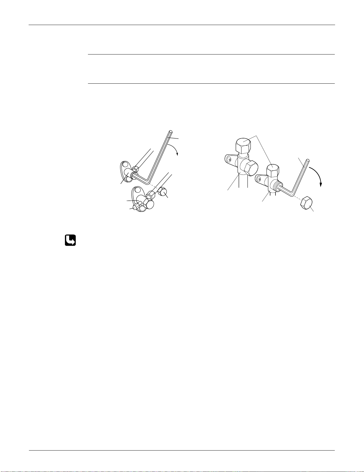
Pump Down Operation SiUS091133
383 Trial Operation and Field Settings
1. Pump Down Operation
Outline In order to protect the environment, be sure to conduct pump down operation when relocating or
disposing the unit.
Detail 1) Remove the valve caps from the liquid stop valve and the gas stop valve.
2) Carry out forced cooling operation.
3) After 5 to 10 minutes, close the liquid stop valve with a hexagonal wrench.
4) After 2 to 3 minutes, close the gas stop valve and stop the forced cooling operation.
Refer to page 384 for forced cooling operation.
09/12/15/18 class 24/30/36 class
Gas stop valve
Valve cap
Close
Liquid stop valve
Service port
(R13628)
Hexagonal
wrench
Hexagonal
wrench
(R14474)
Service port
Gas stop valve
Liquid stop valve
Valve cap
Close
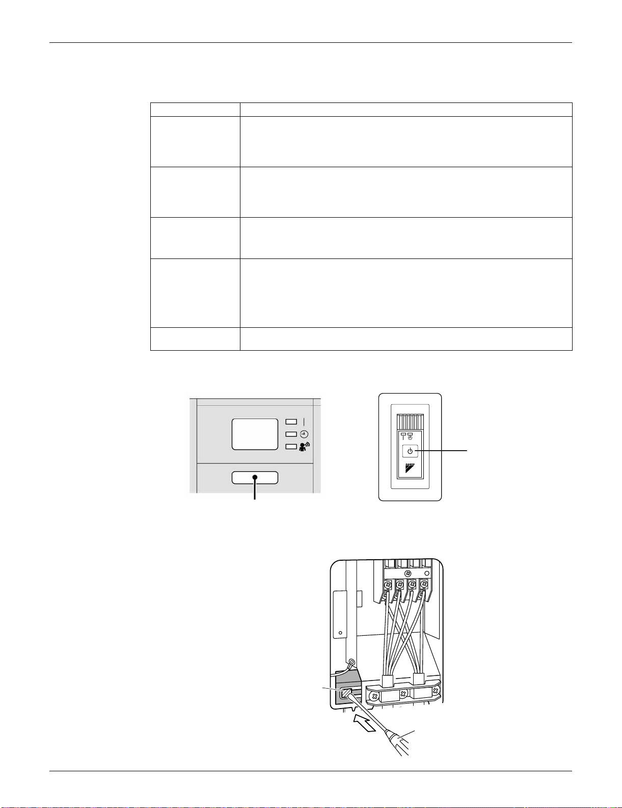
SiUS091133 Forced Cooling Operation
Trial Operation and Field Settings 384
2. Forced Cooling Operation
Indoor Unit
Outdoor Unit
09/12 class
Item Forced Cooling
Conditions The forced cooling operation is allowed when both of the following conditions are
met.
1) The outdoor unit is not abnormal and not in the 3-minute standby mode.
2) The outdoor unit is not operating.
Start The forced cooling operation starts when any of the following conditions is fulfilled.
1) Press the forced cooling operation [ON/OFF] button (SW1) on the indoor unit
for 5 seconds.
2) Press the forced cooling operation [ON/OFF] button (SW1) on the outdoor unit.
Command
frequency
09/12 class: 58 Hz
15/18 class: 66 Hz
24 class: 31 Hz
30/36 class: 55 Hz
End The forced cooling operation ends when any of the following conditions is fulfilled.
1) The operation ends automatically after 15 minutes.
2) Press the forced cooling operation [ON/OFF] button (SW1) on the indoor unit
again.
3) Press the [ON/OFF] button on the remote controller.
4) Press the forced cooling operation [ON/OFF] button (SW1) on the outdoor unit.
Others Protection functions have priority over all other functions during forced cooling
operation.
FTXS series FDXS series
ON/OFF button (SW1)
(R14145)
[ON/OFF] button (SW1)
(R16615)
1
2
3
Push
Screwdriver
(R16614)
Forced cooling
operation
[ON/OFF] button
(SW1)
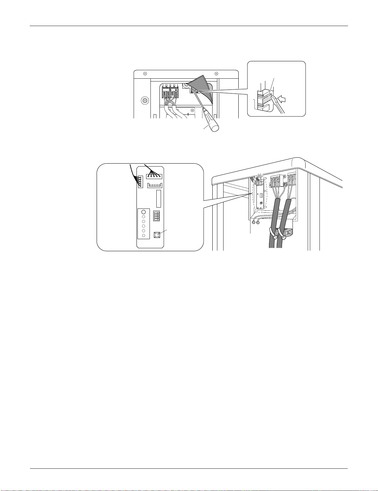
Forced Cooling Operation SiUS091133
385 Trial Operation and Field Settings
15/18 class
24/30/36 class
1
2
3
Screwdriver
(R16616)
Forced cooling operation
[ON/OFF] button (SW1)
Push
LED-A
SW4
ON
ABCD
S102
SW1
S2
Forced cooling
operation
ON/OFF button
(SW1)
(R14475)
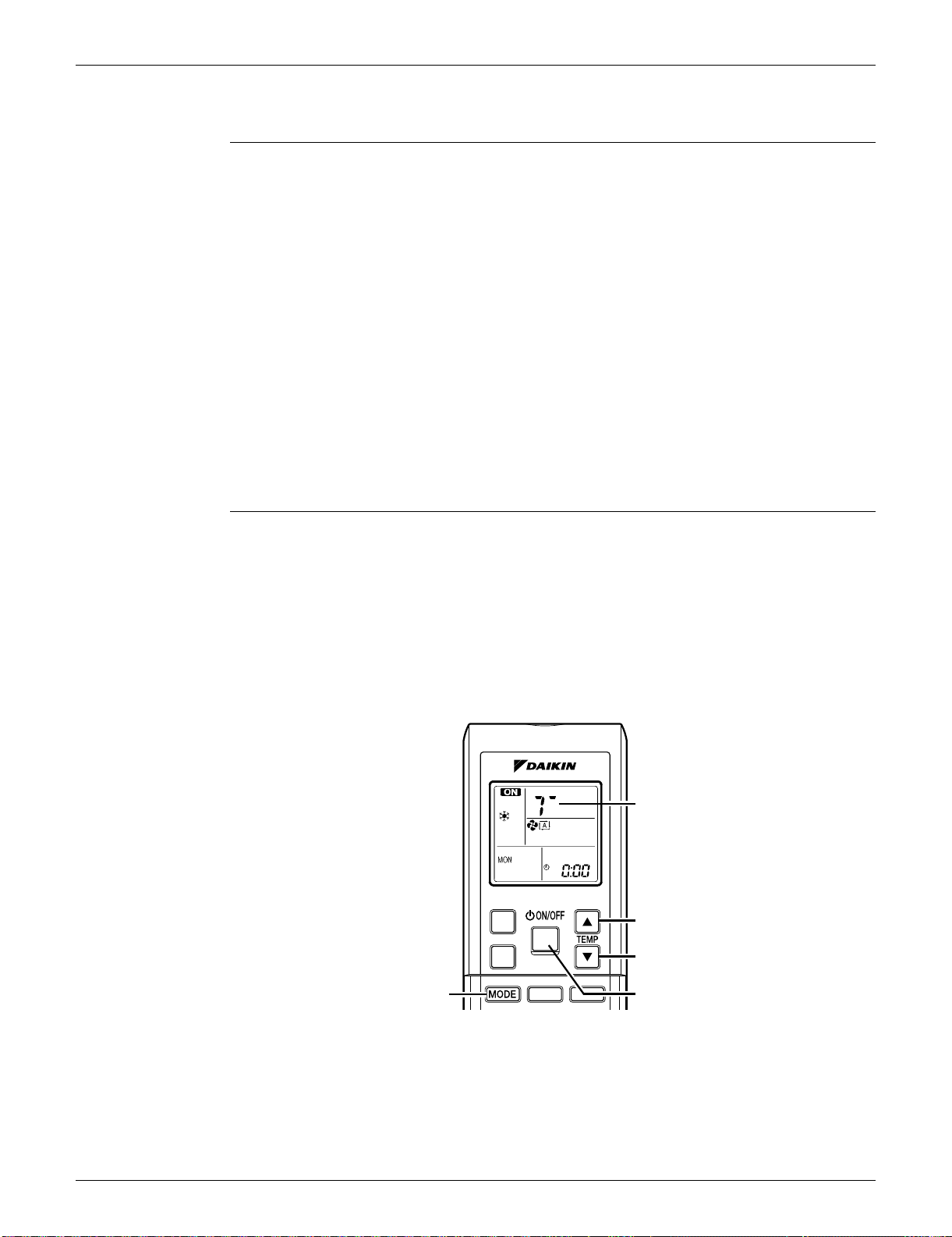
SiUS091133 Trial Operation
Trial Operation and Field Settings 386
3. Trial Operation
Outline 1. Measure the supply voltage and make sure that it falls within the specified range.
2. Trial operation should be carried out in either cooling or heating operation.
3. Carry out the trial operation in accordance with the operation manual to ensure that all functions
and parts, such as louver movement, are working properly.
The air conditioner requires a small amount of power in standby mode. If the system is not to be
used for some time after installation, shut off the circuit breaker to eliminate unnecessary power
consumption.
If the circuit breaker trips to shut off the power to the air conditioner, the system backs up the
operation mode. The system then restarts operation with the previous operation mode when the
circuit breaker is restored.
In cooling operation, select the lowest programmable temperature; in heating operation, select the
highest programmable temperature.
Trial operation may be disabled in either operation mode depending on the room temperature.
After trial operation is complete, set the temperature to a normal level.
(26 ~ 28°C (78.8 ~ 82.4°F) in cooling, 20 ~ 24°C (68 ~ 75.2°F) in heating)
For protection, the system does not start for 3 minutes after it is turned off.
Detail ARC452 Series
(1) Press the [ON/OFF] button to turn on the system.
(2) Press the both of [TEMP] buttons and the [MODE] button at the same time.
(3) Press the [MODE] button twice.
(T appears on the display to indicate that trial operation is selected.)
(4) Press the [MODE] button and select the operation mode.
(5) Trial operation terminates in approx. 30 minutes and switches into normal mode. To quit trial
operation, press the [ON/OFF] button.
(R14476)
(2)
(2) (3) (4)
(1) (5)
(2)
(3)
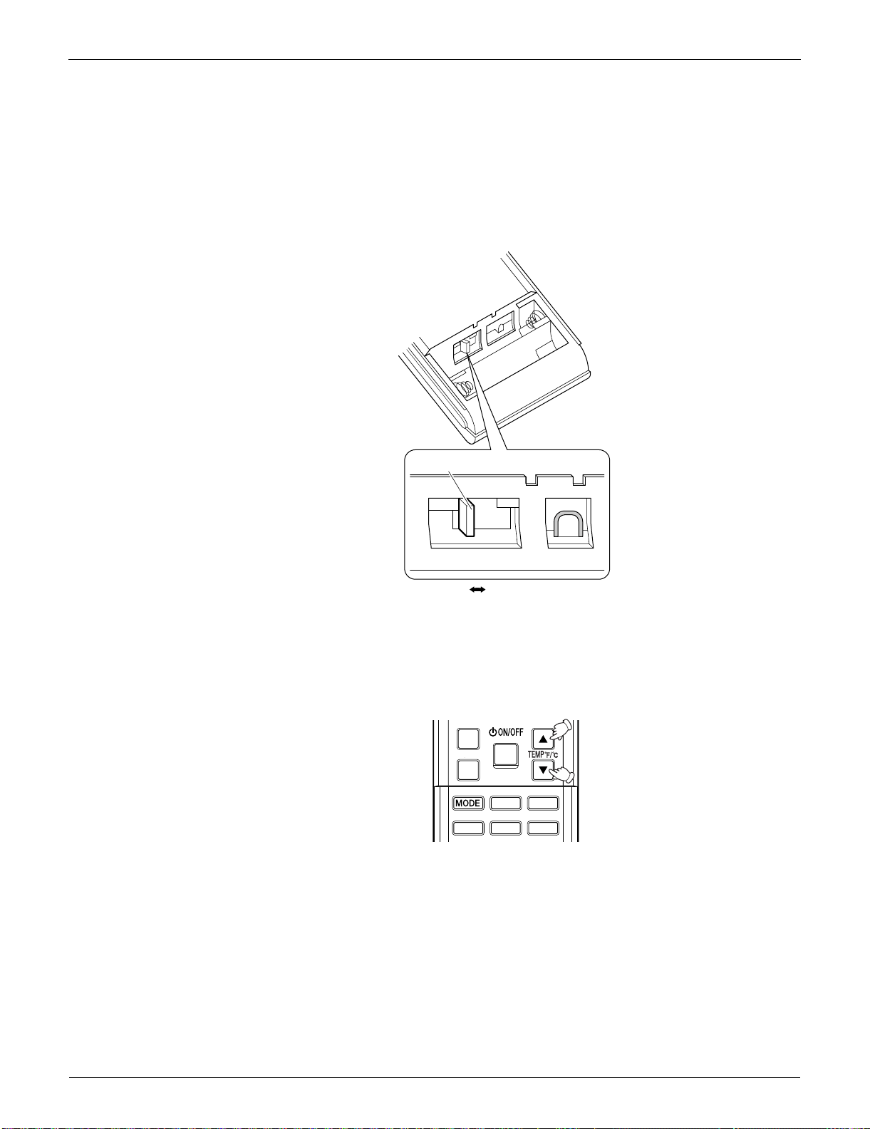
Field Settings SiUS091133
387 Trial Operation and Field Settings
4. Field Settings
4.1 Model Type Setting
This remote controller is common to the heat pump model and cooling only model. Use the DIP
switch on the remote controller to set the heat pump model or cooling only model.
Make the setting as shown in the illustration. (The factory set is the heat pump side.)
• Heat pump model: Set the DIP switch to H/P.
• Cooling only model: Set the DIP switch to C/O.
4.2 Temperature Display Switch
You can select Fahrenheit or Celsius for temperature display.
Press the TEMP
and buttons simultaneously for 5 seconds to change the unit of temperature
display.
(R12275)
DIP switch
H/P
C/O
(R14477)
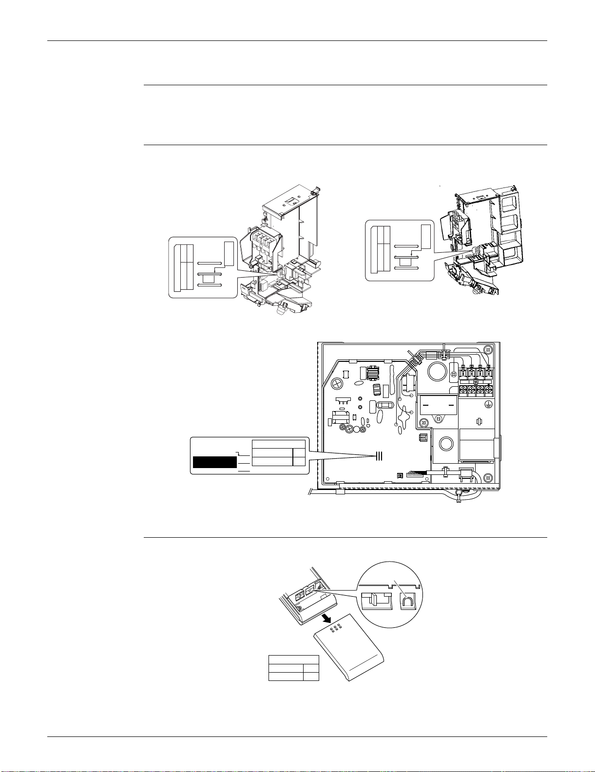
SiUS091133 Field Settings
Trial Operation and Field Settings 388
4.3 When 2 Units are Installed in 1 Room
Outline When 2 indoor units are installed in 1 room, 1 of the 2 indoor units and the corresponding wireless
remote controller can be set for different addresses.
Both the indoor unit PCB and the wireless remote controller need alteration.
Indoor Unit PCB Cut the address setting jumper JA on the control PCB.
Wireless Remote
Controller
Cut the address setting jumper.
FTXS09/12LVJU FTXS15/18/24/30/36LVJU
FDXS series
ADDRESS
JC
JA
JB
ADDRESS:JA
EXIST
1
CUT
2
(R9665)
JA
ADDRESS
ADDRESS
JC
JA
JB
ADDRESS:JA
EXIST
1
CUT
2
ADDRESS: JA
CUT
EXIST
1
2
ADDRESS
JA
JC
JB
(R16921)
(R13525)
ADDRESS
EXIST
CUT
1
2
Jumper
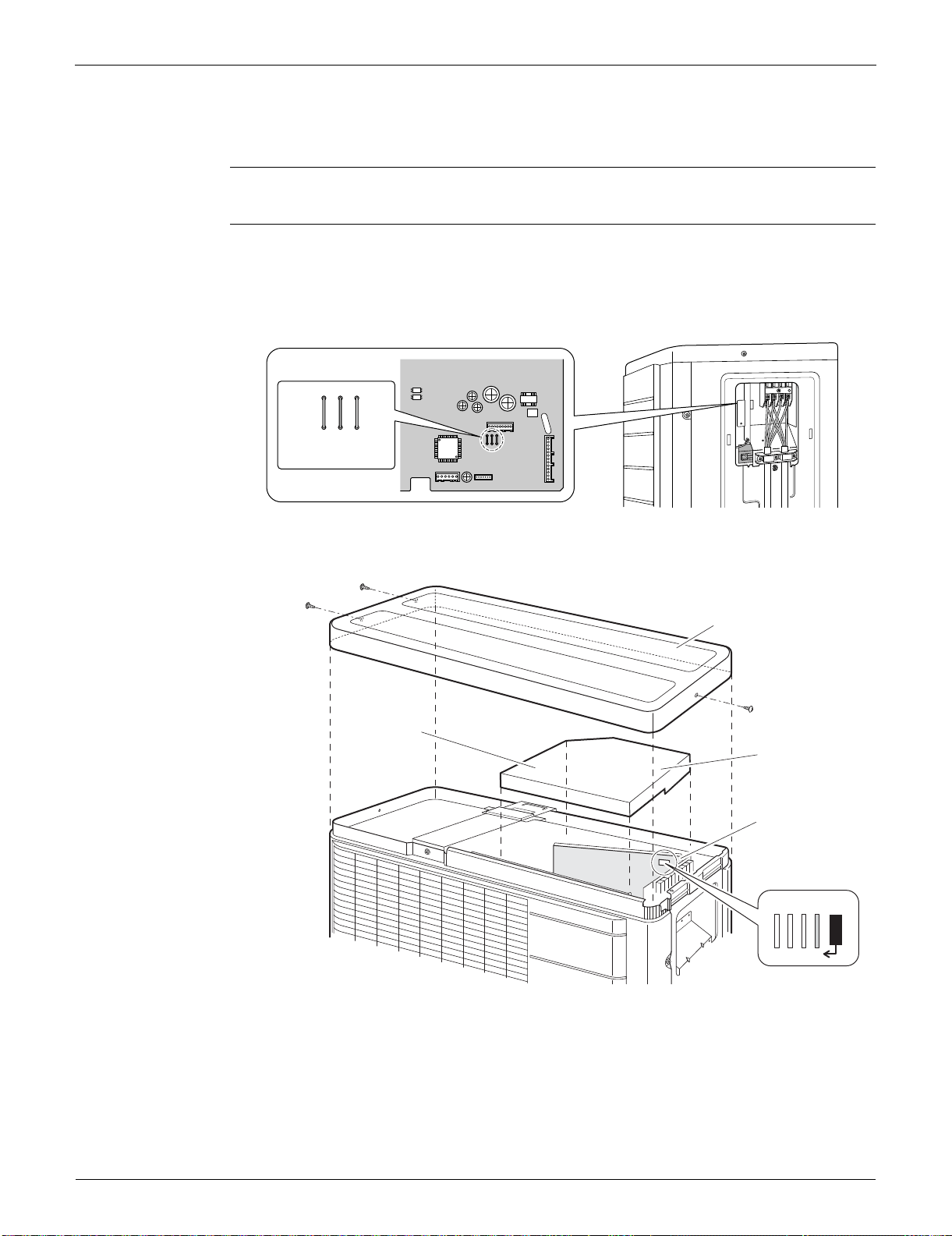
Field Settings SiUS091133
389 Trial Operation and Field Settings
4.4 Facility Setting Jumper and Switch (Cooling at Low
Outdoor Temperature)
Outline This function is limited only for facilities (the target of air conditioning is equipment such as
computer. Never use it in spaces occupied by humans such as a residence or office.
Detail You can expand the operation range to –10°C (14°F) by cutting the jumper or turning on switch on
the outdoor unit PCB. If the outdoor temperature falls to –18°C (–0.4°F) or lower, the operation
stops. If the outdoor temperature rises, the operation starts again.
09/12 class
15/18 class
1
2
3
S70
S40
S2
S90
J5
J4
J3
(R12187)
Cut the jumper J4.
J5
J7
J8
J6
GND
Top panel
PCB
1) Remove the
3 screws.
Drip proof
cover
2) Remove the
drip proof
cover.
3) Cut the
jumper J6.
(R16698)
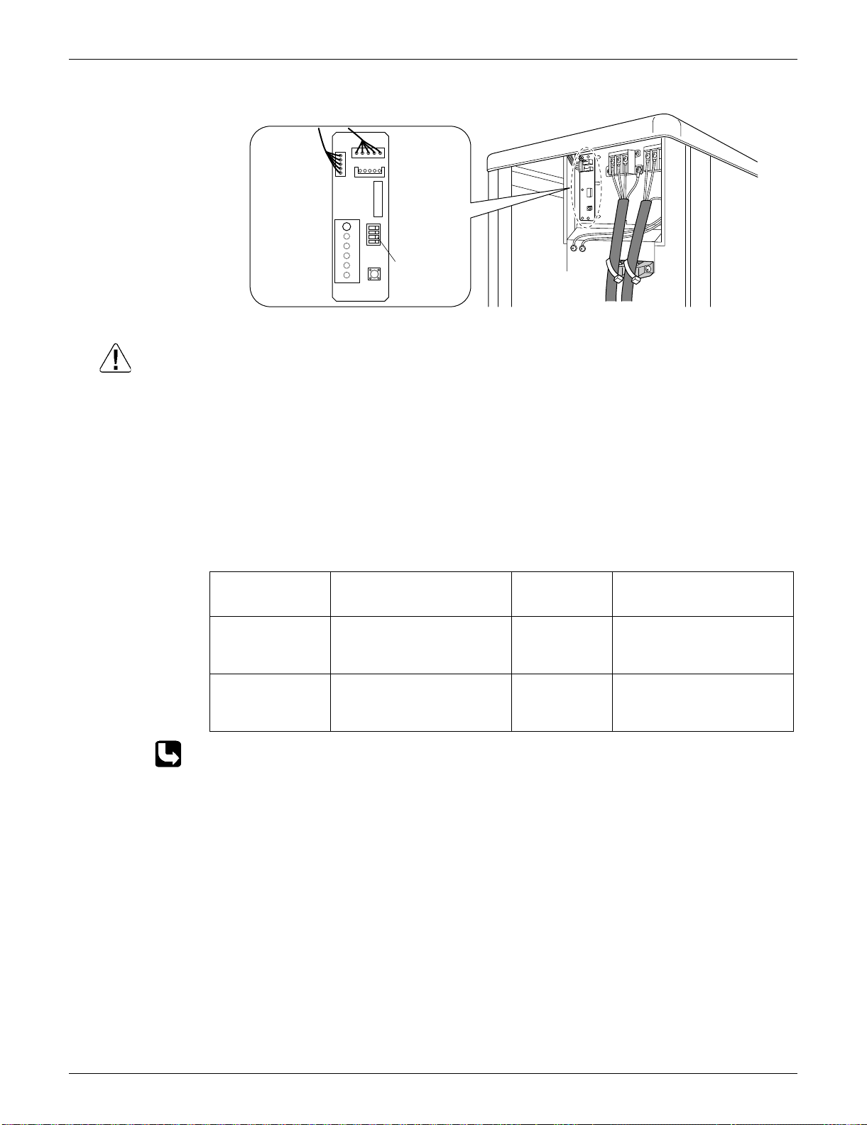
SiUS091133 Field Settings
Trial Operation and Field Settings 390
24/30/36 class
Caution 1. If the outdoor unit is installed where the outdoor heat exchanger of the unit is exposed to direct
wind, provide a windbreak wall.
2. Intermittent noises may be produced by the indoor unit due to the outdoor fan turning on and off
when using facility settings.
3. Do not place humidifiers or other items which might raise the humidity in rooms where facility
settings are being used.
A humidifier might cause dew jumping from the indoor unit outlet vent.
4. Cutting the jumper sets the indoor fan tap to the highest position. (09/12/15/18 class)
5. Use the indoor unit at the highest level of airflow rate. (24/30/36 class)
4.5 Jumper Settings
For the location of the jumper, refer to the following pages.
Indoor unit; page 14, 17, 20
SW4
ON
ABCD
SW1
(R14478)
Turn on
the switch
SW4-B.
LED-A
S2
S102
Jumper Function When
connected
(factory set)
When cut
JB (on indoor unit
PCB)
Fan speed setting when
compressor stops for
thermostat OFF. (effective only
at cooling operation)
Fan speed
setting; Remote
controller
setting
Fan rpm is set to “0” <Fan
stop>
JC (on indoor unit
PCB)
Power failure recovery function Auto-restart The unit does not resume
operation after recovering from
a power failure. Timer ON/OFF
settings are cleared.
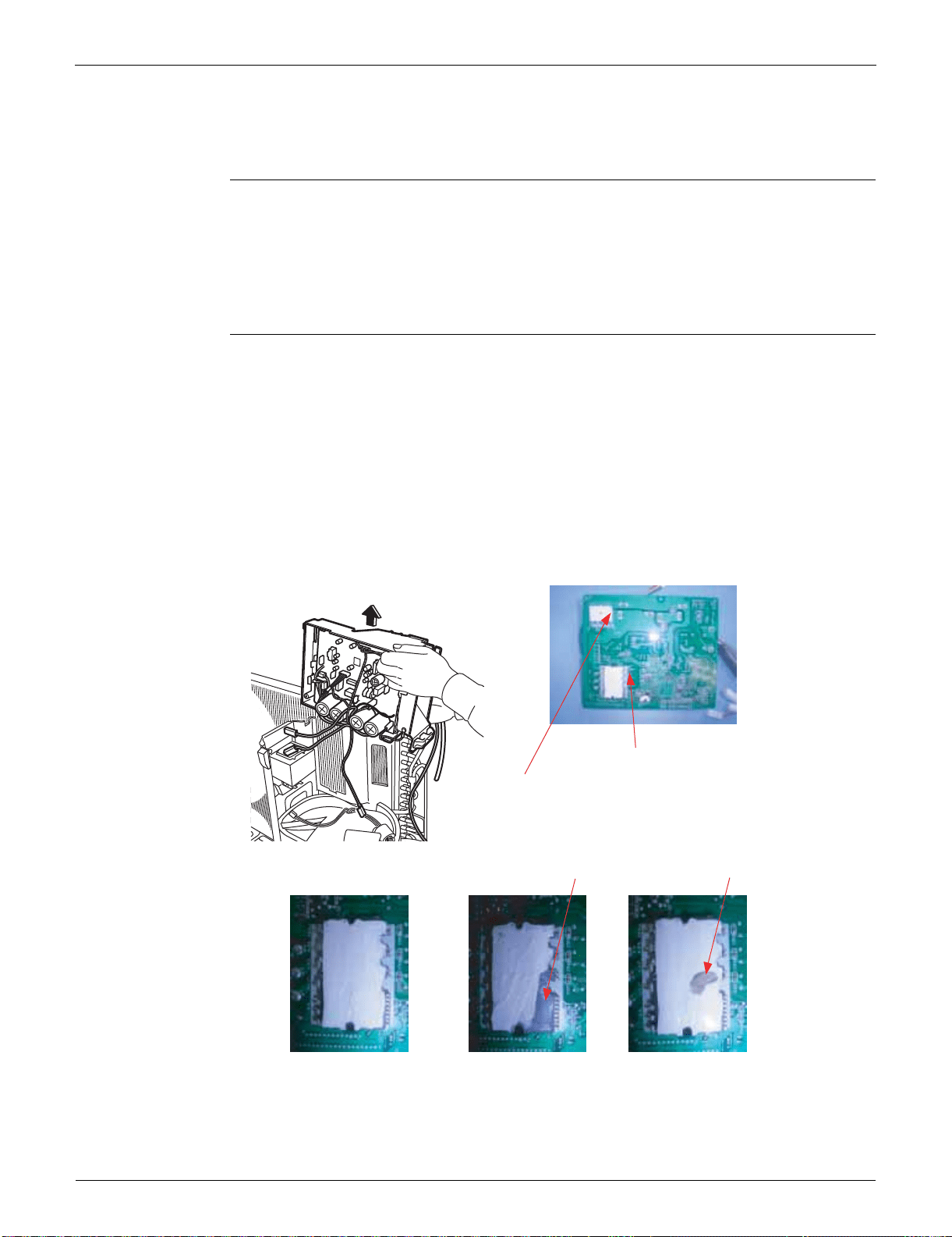
Application of Silicon Grease to a Power Transistor and a Diode Bridge SiUS091133
391 Trial Operation and Field Settings
5. Application of Silicon Grease to a Power Transistor
and a Diode Bridge
Applicable
Models
All outdoor units using an inverter type compressor for room air conditioner.
When the printed circuit board (PCB) of an outdoor unit is replaced, it is required that silicon grease
(*1) be precisely applied to the heat radiation part (the contact point to the radiation fin) of the
power transistor and the diode bridge.
*1: Parts number of the silicon grease – 1172698 (Drawing number 3FB03758-1)
Details The silicon grease is essential for proper heat radiation of the power transistor and the diode
bridge. Applying the grease should be implemented in accordance with the following instruction.
Note: There is a possibility of failure and smoke emission in case of poor heat radiation.
Wipe off the old silicon grease completely off the radiation fin.
Apply silicon grease evenly to the whole surface of the radiation fin.
Do not leave any foreign object such as solder or paper waste between the power transistor and
the radiation fin, or the diode bridge and the radiation fin.
Tighten the screws of the power transistor and the diode bridge, and contact to the radiation fin
without any gap.
<Example>
The shape of the electrical box and PCB vary depending on the model.
(R9056)
OK : Evenly applied
silicon grease.
NG : Not evenly
applied
Take out a PCB
Diode bridge
(Diode bridge, Rectifier stack, etc.)
Power transistor
(TRM, TPM, IGBT, IPM, SPM, etc.)
Not applied.
Paper waste
NG : Foreign object

SiUS091133
Appendix 392
Part 9
Appendix
1. Piping Diagrams......................................................................................393
1.1 Indoor unit ................................................................................................ 393
1.2 Outdoor Unit.............................................................................................396
2. Wiring Diagrams......................................................................................399
2.1 Indoor Unit................................................................................................399
2.2 Outdoor Unit.............................................................................................401
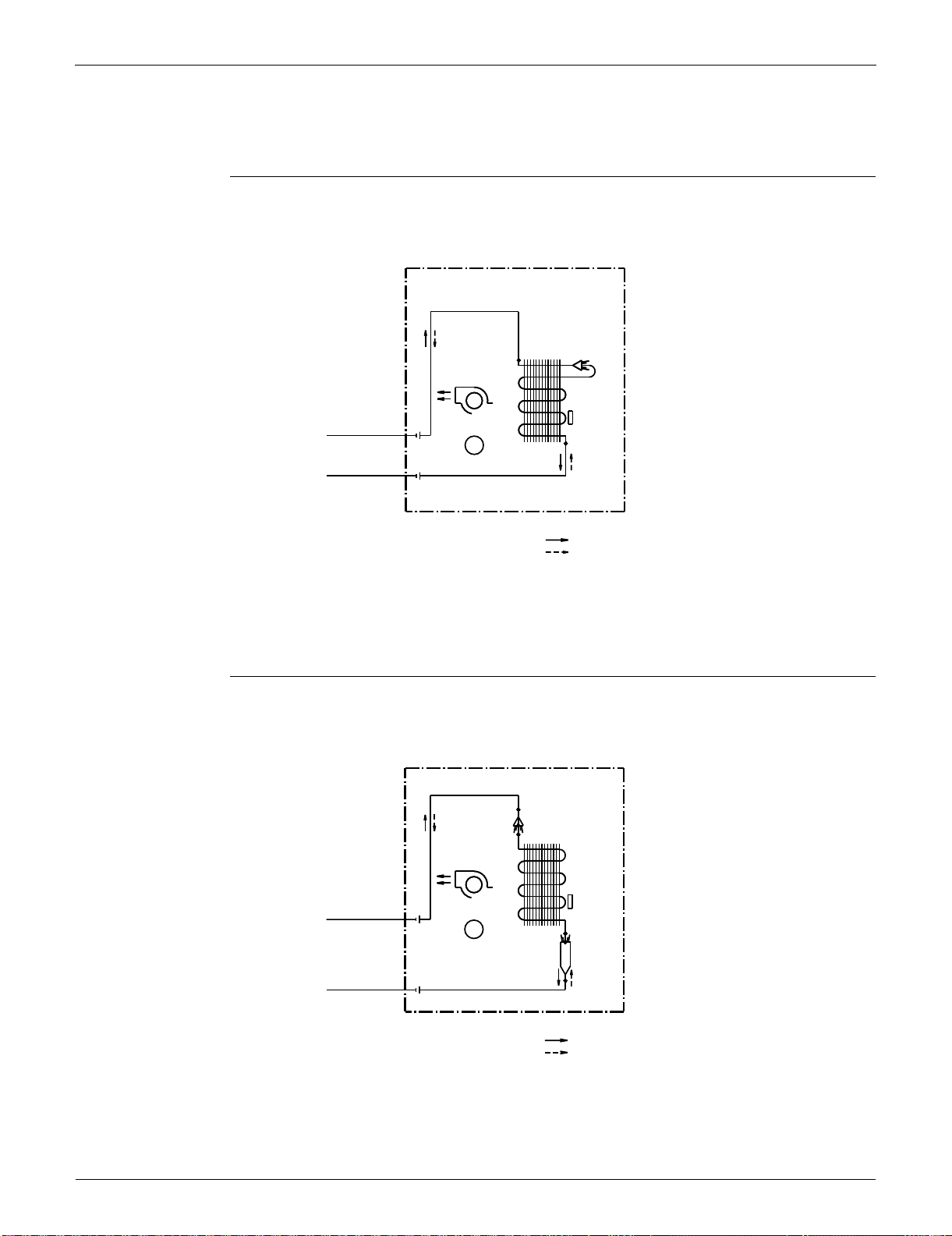
Piping Diagrams SiUS091133
393 Appendix
1. Piping Diagrams
1.1 Indoor unit
FTXS09/12LVJU
FTXS15/18LVJU
INDOOR UNIT
1/4 CuT
HEAT EXCHANGER
CROSS FLOW FAN
FIELD PIPING
1/4 CuT
M
FAN MOTOR
FIELD PIPING
3/8 CuT
3/8 CuT
REFRIGERANT FLOW
COOLING
HEATING
4D074606
THERMISTOR
ON HEAT EXCH.
INDOOR UNIT
5/16 CuT
DISTRIBUTOR
HEAT EXCHANGER
CROSS FLOW FAN
FIELD PIPING
1/4 CuT
M
FAN MOTOR
HEADER
FIELD PIPING
1/2 CuT
1/2 CuT
REFRIGERANT FLOW
COOLING
HEATING
THERMISTOR
ON HEAT EXCH.
4D074609
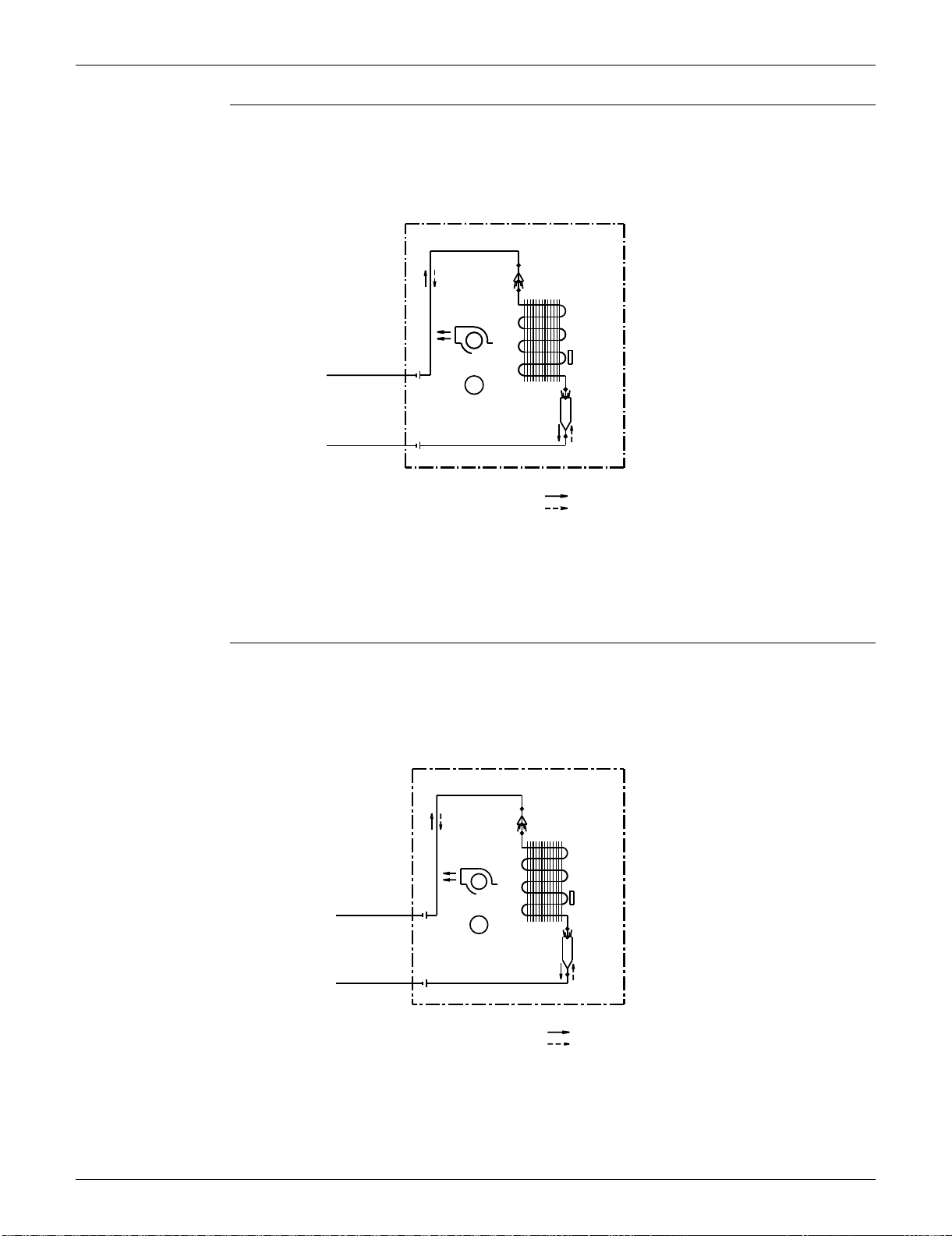
SiUS091133 Piping Diagrams
Appendix 394
FTXS24LVJU
FTXS30/36LVJU
INDOOR UNIT
5/16 CuT
DISTRIBUTOR
HEAT EXCHANGER
CROSS FLOW FAN
M
FAN MOTOR
HEADER
1/2 CuT
REFRIGERANT FLOW
COOLING
HEATING
FIELD PIPING
1/4 CuT
FIELD PIPING
5/8 CuT
THERMISTOR
ON HEAT EXCH.
4D074608
CROSS FLOW FAN
HEAT EXCHANGER
1/2 CuT
5/8 CuT
HEADER
REFRIGERANT FLOW
INDOOR UNIT
HEATING
M
FIELD PIPING
COOLING
3/8 CuT
FAN MOTOR
FIELD PIPING
5/16 CuT
DISTRIBUTOR
THERMISTOR
ON HEAT EXCH.
4D062742A
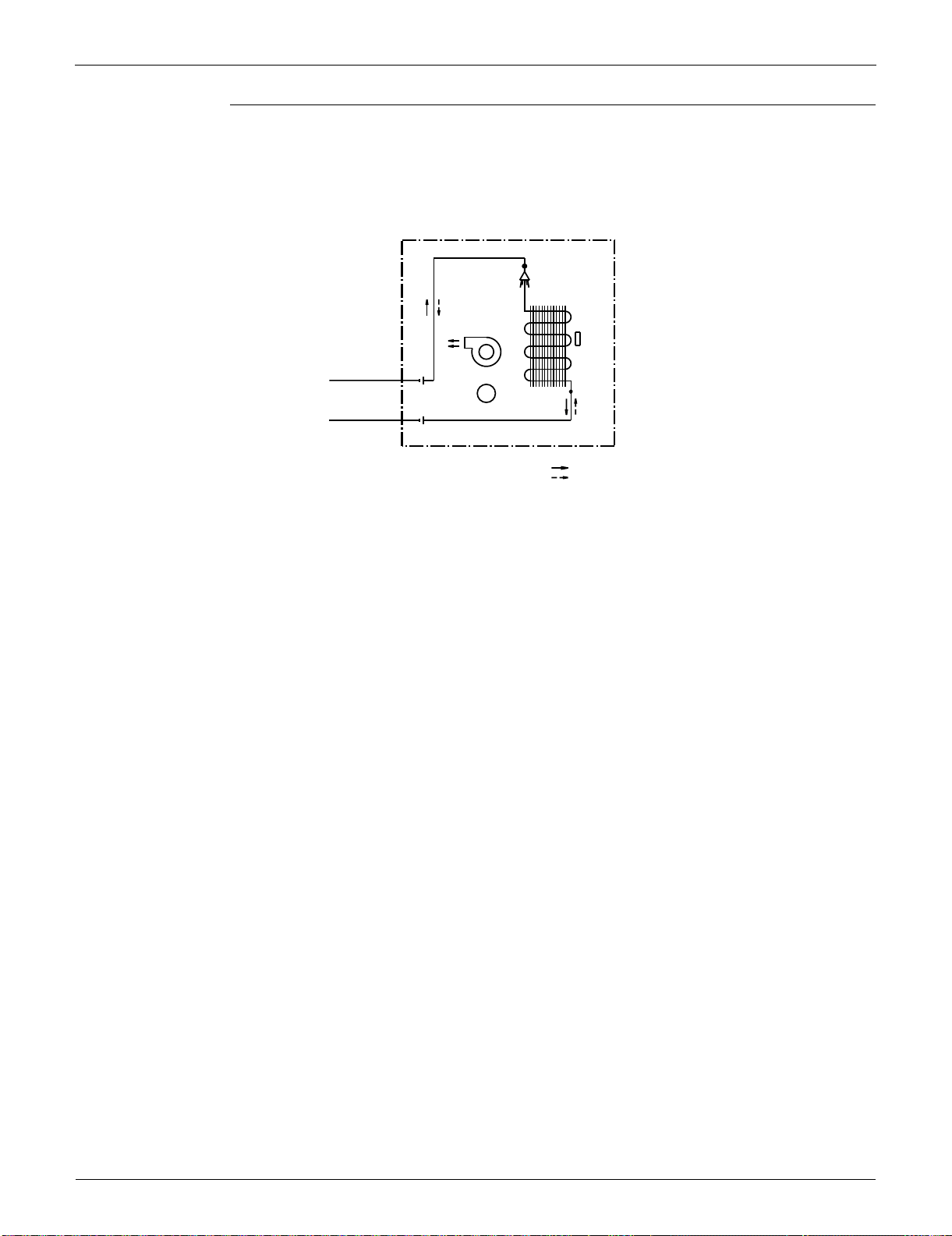
Piping Diagrams SiUS091133
395 Appendix
FDXS09/12LVJU
INDOOR UNIT
(1/4CuT)
HEAT EXCHANGER
FIELD PIPING
(1/4CuT)
SIROCCO FAN
M
FAN MOTOR
(3/8CuT)
FIELD PIPING
(3/8CuT)
REFRIGERANT FLOW
COOLING
HEATING
4D074621
THERMISTOR
ON HEAT EXCH.
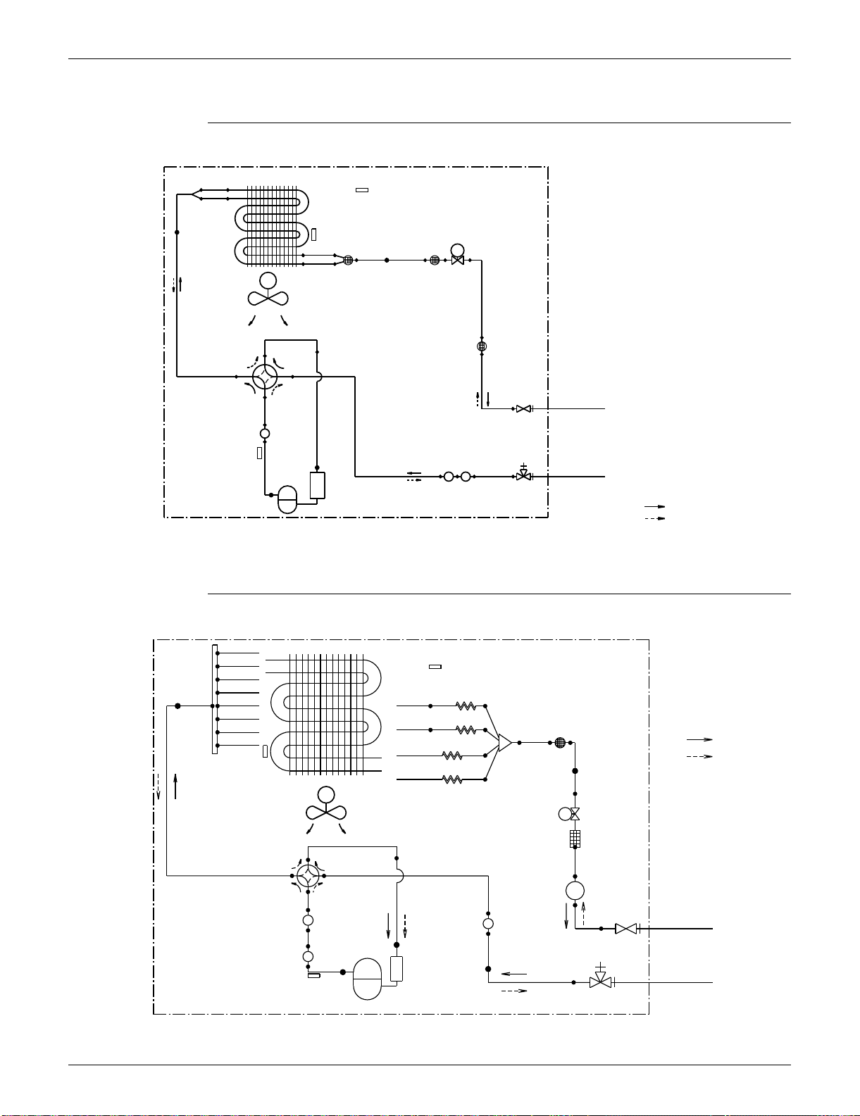
SiUS091133 Piping Diagrams
Appendix 396
1.2 Outdoor Unit
RXS09/12LVJU
RXS15/18LVJU
EV
1/4CuT
OUTDOOR UNIT
M
MUFFLER
3/16CuT
3/16CuT
MUFFLER
1/4CuT
3/8CuT
ACCUMULATOR
FIELD PIPING
5/16CuT
3/8CuT
9/32CuT
3/8CuT
REFRIGERANT FLOW
3/8CuT
HEATING
9/32CuT
3/8CuT
MUFFLER
COMPRESSOR
(1/4CuT)
1/4CuT
(3/8CuT)
COOLING
5/16CuT
HEAT EXCHANGER
PROPELLER FAN
FIELD PIPING
3/8CuT
φ.5/32×ID. 5/64CuT
OUTDOOR TEMPERATURE
THERMISTOR
ELECTRONIC
EXPANSION
VALVE
HEAT EXCHANGER
THERMISTOR
MUFFLER
WITH
FILTER
MUFFLER
WITH
FILTER
MUFFLER
WITH
FILTER
LIQUID STOP
VALVE
GAS STOP
VALVE
DISCHARGE PIPE
THERMISTOR
FOUR WAY
VALVE
ON : HEATING
3D074282
OUTDOOR UNIT
HEAT EXCHANGER
5/16CuT
(
7.9
)
5/16CuT
(
7.9
)
5/16CuT
(
7.9
)
5/16CuT
(
7.9
)
CAPILLARY TUBE 1
5/16CuT
(
7.9
)
5/16CuT
(
7.9
)
CAPILLARY TUBE 2
5/16CuT
(
7.9
)
REFRIGERANT FLOW
5/16CuT
(
7.9
)
CAPILLARY TUBE 3
COOLING
HEATING
CAPILLARY TUBE 4
M
PROPELLER FAN
EV
FILTER
RECEIVER
MUFFLER
FIELD PIPING
MUFFLER
(
1/4 CuT
)
(
6.4
)
MUFFLER
FIELD PIPING
(
1/2 CuT
)
(
12.7
)
COMPRESSOR
UNIT=INCH
(
mm
)
HEAT
EXCHANGER
THERMISTOR
OUTDOOR TEMPERATURE
THERMISTOR
(
4.0
)
5/32CuT
(
4.0
)
5/32CuT
(
7.9
)
5/16CuT
(
7.9
)
5/16CuT
(
4.0
)
5/32CuT
(4.0)
5/32CuT
(
6.4
)
1/4CuT
MUFFLER
WITH
FILTER
(
6.4
)
1/4CuT
(6.4)
1/4CuT
(6.4)
1/4CuT
(9.5)
3/8CuT
ELECTRONIC
EXPANSION
VALVE
(6.4)
1/4CuT
(12.7)
1/2CuT
LIQUID
STOP VALVE
GAS STOP VALVE
WITH SERVICE PORT
(
9.5
)
3/8CuT
(
12.7
)
1/2CuT
(
12.7
)
1/2CuT
(
12.7
)
1/2CuT
FOUR WAY
VALVE
ON : HEATING
(
7.9
)
5/16CuT
(
7.9
)
5/16CuT
(
7.9
)
5/16CuT
DISCHARGE PIPE
THERMISTOR
(
12.7
)
1/2CuT
3D074451
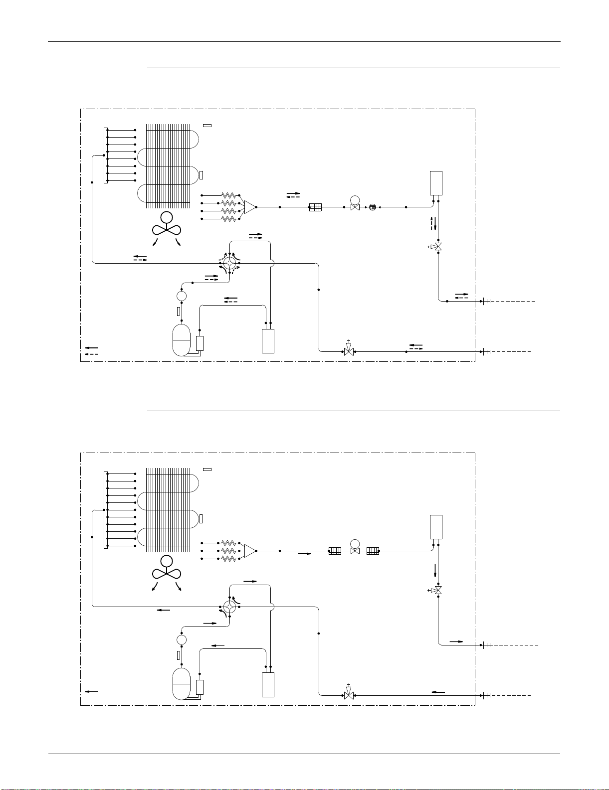
Piping Diagrams SiUS091133
397 Appendix
RXS24LVJU
RKS30/36LVJU
3D074442
OUTDOOR UNIT
HEAT EXCHANGER
5/16CuT
5/16CuT
HEADER
5/16CuT
5/16CuT
5/16CuT
5/16CuT
5/16CuT
1/2CuT
5/16CuT
RECEIVER
5/32CuT
5/16CuT
EV
3/8CuT3/8CuT 3/8CuT 3/8CuT 3/8CuT
FILTERDISTRIBUTOR
DC FAN MOTOR
M
3/8CuT
CAPILLARY TUBE
PROPELLER FAN
5/8CuT
5/8CuT
5/16CuT
3/8CuT
5/16CuT
MUFFLER
FIELD PIPING
LIQUID (1/4CuT)
3/8CuT
5/8CuT
5/8CuT
5/8CuT
5/16CuT
FIELD PIPING
GAS (5/8CuT)
5/8CuT
5/8CuT
ACCUMULATORACCUMULATOR
HEATING
REFRIGERANT FLOW
COOLING
COMPRESSOR
OUTDOOR TEMPERATURE
THERMISTOR
HEAT EXCHANGER (CONDENSER)
THERMISTOR
4-WAY
VALVE
ON: HEATING
MUFFLER
WITH
FILTER
ELECTRONIC
EXPANSION
VALVE
LIQUID LINE
STOP VALVE
GAS LINE
STOP VALVE
DISCHARGE PIPE
THERMISTOR
OUTDOOR UNIT
HEAT EXCHANGER
3/8CuT
5/16CuT
HEADER
5/16CuT
5/16CuT
5/16CuT
5/16CuT
5/16CuT
5/16CuT
RECEIVER
1/2CuT
5/16CuT
5/16CuT
5/32CuT
5/16CuT
5/16CuT
EV
5/16CuT
3/8CuT3/8CuT 3/8CuT
5/16CuT
FILTERFILTERDISTRIBUTOR
DC FAN MOTOR
M
CAPILLARY TUBE
3/8CuT
PROPELLER FAN
5/8CuT
5/8CuT
3/8CuT
MUFFLER
3/8CuT
5/8CuT
5/8CuT
5/8CuT
5/16CuT
REFRIGERANT FLOW
COMPRESSOR
COOLING
5/8CuT
ACCUMULATORACCUMULATOR
DISCHARGE PIPE
THERMISTOR
4-WAY
VALVE
GAS LINE
STOP VALVE
LIQUID LINE
STOP VALVE
ELECTRONIC
EXPANSION
VALVE
FIELD PIPING
LIQUID (3/8 CuT)
FIELD PIPING
GAS (5/8 CuT)
HEAT EXCHANGER (CONDENSER)
THERMISTOR
OUTDOOR TEMPERATURE
THERMISTOR
3D074193
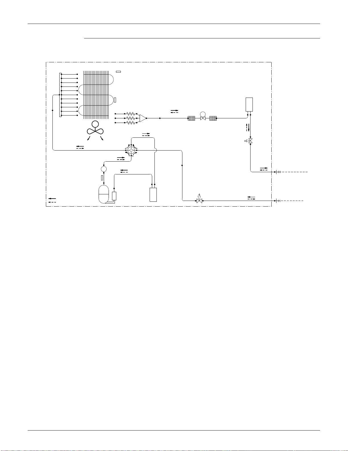
SiUS091133 Piping Diagrams
Appendix 398
RXS30/36LVJU
OUTDOOR UNIT
HEAT EXCHANGER
3/8CuT
5/16CuT
HEADER
5/16CuT
5/16CuT
5/16CuT
5/16CuT
5/16CuT
5/16CuT
RECEIVER
1/2CuT
5/16CuT
5/16CuT
5/32CuT
5/16CuT
5/16CuT
EV
5/16CuT
3/8CuT3/8CuT 3/8CuT
5/16CuT
FILTERFILTER
DISTRIBUTOR
DC FAN MOTOR
M
CAPILLARY TUBE
3/8CuT
PROPELLER FAN
5/8CuT
5/8CuT
3/8CuT
MUFFLER
FIELD PIPING
LIQUID (3/8 CuT)
3/8CuT
5/8CuT
5/8CuT
5/8CuT
5/16CuT
REFRIGERANT FLOW
COMPRESSOR
COOLING
FIELD PIPING
HEATING
GAS (5/8 CuT)
5/8CuT
ACCUMULATORACCUMULATOR
DISCHARGE PIPE
THERMISTOR
4-WAY
VALVE
ON:HEATING
GAS LINE
STOP VALVE
LIQUID LINE
STOP VALVE
ELECTRONIC
EXPANSION
VALVE
HEAT EXCHANGER (CONDENSER)
THERMISTOR
OUTDOOR TEMPERATURE
THERMISTOR
3D074192
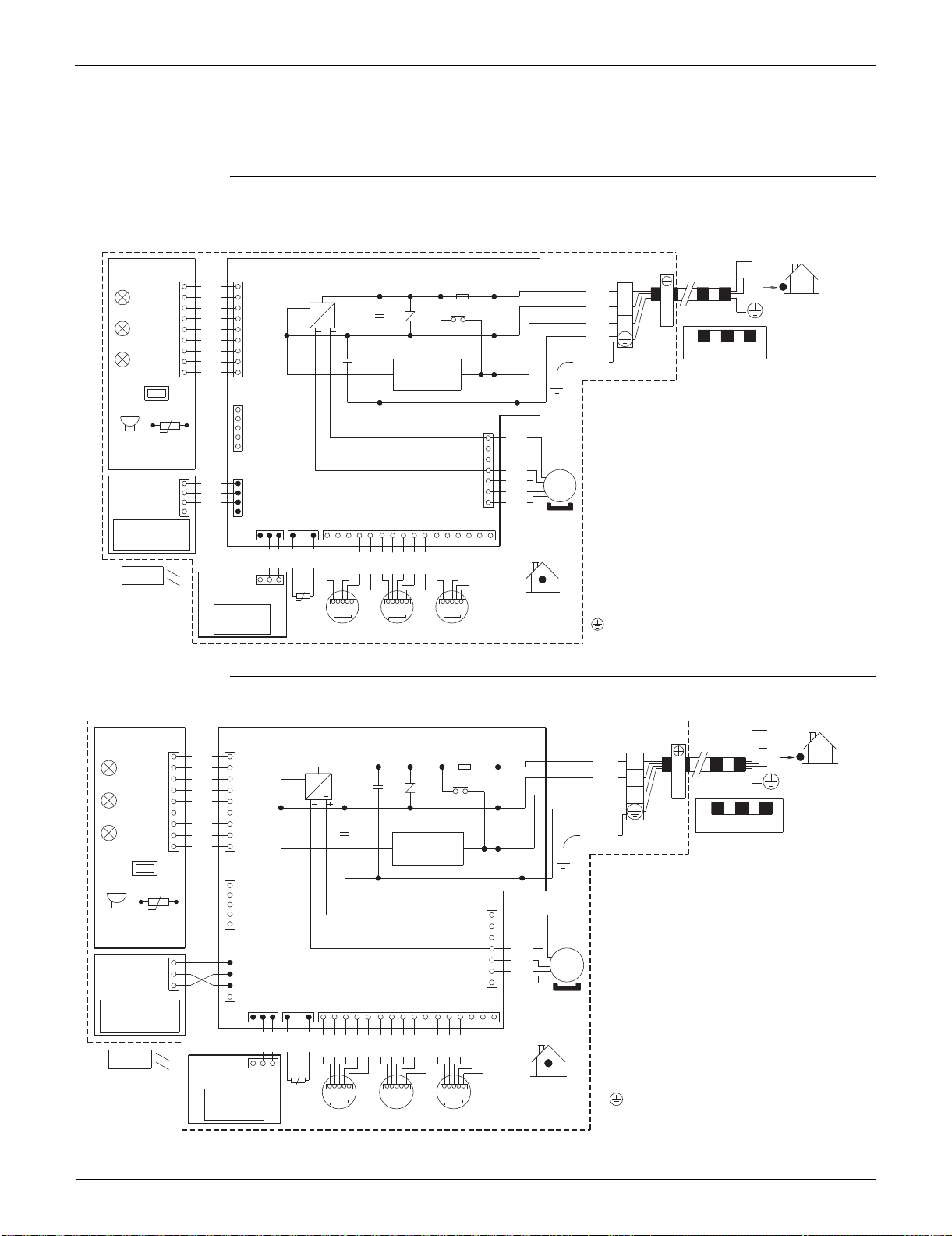
Wiring Diagrams SiUS091133
399 Appendix
2. Wiring Diagrams
2.1 Indoor Unit
FTXS09/12LVJU
FTXS15/18/24/30/36LVJU
1
FU1
X1M
PCB1
PCB3
S46
S49
2
H1
F1U
BLK
11
BLK
1
LED1
3
BLK
3.15A
H1P
WHT
~
OUTDOOR
2
BLK
C102 V1
BLK
LED2
RED
3
H2
MR10
BLK
GRN
H2P
BLK
FIELD WIRING.
BLK
LED3
GRN
C101
BLK
/
H3
YLW
H3P
99
BLK
CAUTION
FG
SW1
S21
t°
S1
HA
7
RED
RTH1BZ
R1T
4
BLU
S25
MS
BRN
BLK
11
PCB4
ORG
BLK
3~
S26
BLK
1
WHT
S41
S47 S32
44
BLK
M1F
16 41211214313110273596118 15
BLK
BLK
BLK
BLK
BLK
PNK
PNK
PNK
BLU
BLU
BLU
RED
RED
RED
ORG
ORG
ORG
YLW
YLW
YLW
S48
PCB2
t°
1
3
INDOOR
R2T
MSW MSWMSW
M2SM1S M3S
WIRELESS
REMOTE
CONTROLLER
INTELLIGENT EYE
SENSOR
SIGNAL
RECEIVER
TRANSMISSION
CIRCUIT
NOTE THAT OPERATION WILL RESTART
AUTOMATICALLY IF THE MAIN POWER SUPPLY
IS TURNED OFF AND THEN BACK ON AGAIN.
BZ
C101, C102
FG
F1U
H1P~H3P
MR10
M1F
M1S~M3S
PCB1~PCB4
R1T, R2T
S1~S49
SW1
V1
X1M
: BUZZER
: CAPACITOR
: FRAME GROUND
: FUSE
: PILOT LAMP
: MAGNETIC RELAY
: FAN MOTOR
: SWING MOTOR
: PRINTED CIRCUIT BOARD
: THERMISTOR
: CONNECTOR
: OPERATION SWITCH
: VARISTOR
: TERMINAL STRIP
: PROTECTIVE GROUND
3D058246F
1
X1M
PCB1PCB3
S46S49
2
H1
BLK
11
BLK
1
3
BLK
3.15A
WHT
~
OUTDOOR
2
BLK
C102 V1
BLK
RED
3
H2
MR10
BLK
GRN
BLK
FIELD WIRING.
BLK
C101
BLK
H3
99
BLK
CAUTION
FG
SW1
S21
t°
S1
HA
7
RED
BZ
4
BLU
S25
BLK
MS
3~
BRN
1
1
PCB4
BLK
ORG
S36
1
WHT
3
S41S47 S32
BLK
4
M1F
12
1
16 14 11
1
73
1
8 1552213910 643
BLK
BLK
BLK
BLK
BLK
PNK
PNK
PNK
BLU
BLU
BLU
RED
RED
RED
ORG
ORG
ORG
YLW
YLW
YLW
S48PCB2
t°
1
3
INDOOR
R2T
MSW MSWMSW
M1S M3SM2S
GRN
/
YLW
SIGNAL
RECEIVER
WIRELESS
REMOTE
CONTROLLER
INTELLIGENT EYE
SENSOR
RTH1
R1T
LED3
H3P
LED2
H2P
LED1
H1P
TRANSMISSION
CIRCUIT
FU1
F1U
NOTE THAT OPERATION WILL RESTART
AUTOMATICALLY IF THE MAIN POWER SUPPLY
IS TURNED OFF AND THEN BACK ON AGAIN.
BZ
C101, C102
FG
F1U
H1P~H3P
MR10
M1F
M1S~M3S
PCB1~PCB4
R1T
,
R2T
S1~S49
SW1
V1
X1M
: BUZZER
: CAPACITOR
: FRAME GROUND
: FUSE
: PILOT LAMP
: MAGNETIC RELAY
: FAN MOTOR
: SWING MOTOR
: PRINTED CIRCUIT BOARD
: THERMISTOR
: CONNECTOR
: OPERATION SWITCH
: VARISTOR
: TERMINAL STRIP
: PROTECTIVE GROUND
3D060942H
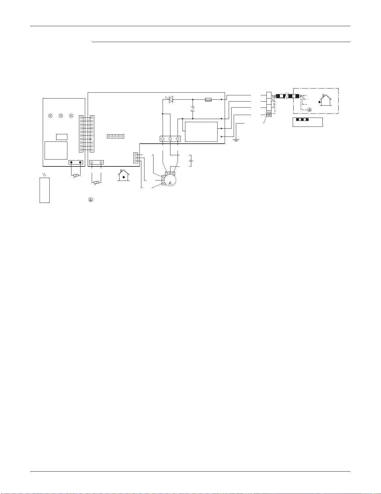
SiUS091133 Wiring Diagrams
Appendix 400
FDXS09/12LVJU
X1M
A1P
11BLK
A2P
H1
2
WHT 2
®
F1U
3
V1TR
RED 3
OUTDOOR
3.15A
LED LED
LED
S1
S26
GRN
H2
11
FIELD WIRING.
H3PH2PH1P
GRN/YLW
H3
CAUTION
()
GND
631
S21
S1W
S1
RED BLK
S7
1010
1GRY
YLW
RTH1
S32
2121
3
C1
WHT
BRNBRN
t°
M
t°
1~
Q1M
PPL
R1T
INDOOR
130°C
BLU
R2T
M1F
WIRELESS
REMOTE
CONTROLLER
TRANSMISSION
CIRCUIT
NOTE THAT OPERATION WILL
RESTART AUTOMATICALLY IF
THE MAIN POWER SUPPLY IS
TURNED OFF AND THEN BACK
ON AGAIN.
H1P~H3P
M1F
A1P~A2P
Q1M
R1T~R2T
S1~S32, RTH1
S1W
V1TR
X1M
: PILOT LAMP
: FAN MOTOR
: PRINTED CIRCUIT BOARD
: THERMAL PROTECTOR (FOR MOTOR)
: THERMISTOR
: CONNECTOR
: OPERATION SWITCH
: TRIAC
: TERMINAL BLOCK
: PROTECTIVE GROUND
: CAPACITOR (M1F)
: FUSE
C1
F1U
SIGNAL
RECEIVER
TERMINAL FOR
CENTRALIZED CONTROL
3D073998B
Wiring Diagrams SiUS091133
401 Appendix
2.2 Outdoor Unit
RXS09/12LVJU
RXS15/18LVJU
NOTE
1. REFER TO THE NAMEPLATE FOR THE POWER REQUIREMENTS.
FIELD WIRING
INDOOR
MRM20
N=2
WHT
IPM1
FU3
Z3C
X1M
DB1
L1R
HR1
20A
HR2
AC1
L1
~+
BRN
+
1L
1
BLK
11
MRM10
AC2
++
HN3
V2
WHT
22
2L
2
DB2
HN2
C5
HA2HA1
S
–
+
BLU
GRY
~–
RED
33
3
~+
HL3
C119
HL2
–
++
V3
ORG
C6
FU1
LLL
1
–
Q1
~–
MR30
3.15A
1
WHT
1
V1
–
BLK
L2
GR
GR
PCB2
GRN/YLW
DB3
BLK
BLK
FU2
3.15A
SA1
S11
~+
S10
BLK
BLK
E1
WVU
BLK
IPM2
BLK
99
~–
+
BLK
–
E2
MRCW
GRN
BLU
RED
YLW
S70
S100
Z2C
S90S20 S40
X11A
PCB1
S80
1312
71011113412
16 1 162
N=2
GRN
OUTDOOR
WHT
WHT
BLU
RED
YLW
GRY
BLK
RED
RED
RED
BLU
WHT
BLK
BLK
BLK
BLK
BLK
BLK
YLW
ORG
BLU
RED
BLK
WHT
BRN
ORG
YLW
2
1
t° t°t°
Y1S
Z1C
MS
M
S110
N=4
V
3~
Q1L
U
R1T
R2T R3T
W
SW1
MS
Y1E
(OUTDOOR)
(DISCHARGE)
3~
M1F
M1C
PCB3
(CONDENSER)
C5, C6, C119
DB1, DB2, DB3
FU1, FU2, FU3
IPM1, IPM2
L1 L2
L1
L1R
M1C
M1F
MRCW, MR30, MRM10, MRM20
Q1L
PCB1, PCB2, PCB3
: CAPACITOR
: DIODE BRIDGE
: FUSE
: INTELLIGENT POWER MODULE
: LIVE
: COIL
: REACTOR
: COMPRESSOR MOTOR
: FAN MOTOR
: MAGNETIC RELAY
: OVERLOAD PROTECTOR
: PRINTED CIRCUIT BOARD
S10, S11, S20, S40
S70, S80, S90, S100
S110, HL3, HN3, X11A
R1T, R2T, R3T
SA1
SW1
: CONNECTOR
: THERMISTOR
: SURGE ABSORBER
:
FORCED COOLING OPERATION SWITCH (SW1)
V1, V2, V3
X1M
Y1E
Y1S
Z1C, Z2C, Z3C
GR
: VARISTOR
: TERMINAL STRIP
: ELECTRONIC EXPANSION VALVE COIL
: REVERSING SOLENOID VALVE COIL
: FERRITE CORE
: PROTECTIVE GROUND
: GROUND
3D074402A
FIELD WIRING
INDOOR
L803
IPM
MRM20
N=5
FU3
Z3C
X1M
DB1
TO INDOOR UNIT
L804
HL3
HL2
30A
+
HL1
BLU
~
+
L
1 1
BLK
1
MRM10MRM10
HN1
V2
WHT
2
2
L
2
HN3
++++
HN2
S
C7 C8
WHT
~
–
RED
3
3
––
GR
1
V3
BLK
1
BLK
BLK
FU1
3.15A
–
L
1
BLK
BLK
PCB2
GRN/YLW
MR30
S11
L
2
S10
BLK
DC_N1
DC_P1
N=4
BLK
SA1
GR
BLK
Z2C
BRN
PPL
E1
BLK
WVU
BLK
POWER SUPPLY
HN4 HL4
11 11
DC_N2
DC_P2
BLK
208/230V 60Hz
E2
GRN
DB3
1
Z1C
FU2
3.15A
~+
YLW
PCB1
N=4
S70
S40
MRCW
S90
S20
V1
GRN
BLU
RED
YLW
47321161 162
4
GRY
~–
X11A
OUTDOOR
S12
BLK
BLK
Z4C
N=1
RED
BLU
WHT
BLK
BLK
BLK
BLK
BLK
BLK
RED
BRN
WHT
BLU
ORG
ORG
YLW
1
3
BLU
RED
YLW
S80
3
1
NOTE
S80
t° t°t°
Q1L
M
V
MSMS
3~
RED
RED
U
R1TR2TR3T
W
Y1E
(DISCHARGE)
(OUTDOOR)
MS
3~
M1F
M1C
Y1S
(CONDENSER)
,
1. C7, C8
DB1, DB3
FU1, FU2, FU3
IPM
L1, L2
L803, L804
M1C
M1F
MRCW, MRM10, MRM20, MR30
Q1L
: CAPACITOR
: DIODE BRIDGE
: FUSE
: INTELLIGENT POWER MODULE
: LIVE
: REACTOR
: COMPRESSOR MOTOR
: FAN MOTOR
: MAGNETIC RELAY
: OVERLOAD PROTECTOR
PCB1, PCB2
S10, S11, S12, S20
S40, S70, S80, S90
HL3, HN3, X11A
R1T, R2T, R3T
SA1
: PRINTED CIRCUIT BOARD
: CONNECTOR
: THERMISTOR
: SURGE ABSORBER
V1, V2, V3
X1M
Y1E
Y1S
Z1C, Z2C, Z3C, Z4C
GR
: VARISTOR
: TERMINAL STRIP
: ELECTRONIC EXPANSION VALVE COIL
: REVERSING SOLENOID VALVE COIL
: FERRITE CORE
:PROTECTIVE GROUND
:GROUND
IN CASE OF
COOLING ONLY
TYPE
3D072837
SiUS091133 Wiring Diagrams
Appendix 402
RXS24LVJU
RKS30/36LVJU, RXS30/36LVJU
L1R
GRN
Z6C
GRN
N=1
YLW
N=1
X1M
Z5C
FU3
7
BLU
WHT
RED
M1F
E1
Z1C
N=6
E2
L1
HR2
SA2
HR1
MRM20
3.15A
POWER SUPPLY
V100
N=4
FU1
MS
V2
Z2C
AC1
BLU
MRM10
30A
L
1
3 ~
L2
BRN
6(P)
1
BRN
L
2
S70
+++
9
8
ORG
1
WHT
V9
7(N)
AC2
Z3C
N=3
2
N=3
BLU
TO INDOOR UNIT
BLK
M1C
Z4C
PM1
X11A
U
WHT
U
GR
X2M
GR
RED
5
RED
1
1
1
V
V
MS
RED
YLW
4
YLW
2
FU2
3.15A
2
3 ~
S10
W
W
3
BLU
3
BLU
3
MR30
V3
Q1L
BLK
BLK
PCB1
S40
MRC/W
41
V5
SHEET METAL
S90
S51 S101 S80 S20
5461115
6
1
61
INDOOR
RED
BLU
BLK
BLU
BLU
BLU
BLU
BLU
BLK
GRY
RED
RED
GRN
WHT
WHT
FIELD WIRING
t˚t˚
t˚
ORG
BLU
RED
YLW
151
S102
5
S52
R1T
R2T
R3T
PCB2
M
Y1S
S2
(OUTDOOR)
(DISCHARGE)
LED A
Y1E
(CONDENSER)
SW4
SW1
OUTDOOR
Z1C~Z6C
X1M, X2M
Y1E
V2, V3, V5, V9, V100
SA2
FU1, FU2, FU3
AC1, AC2
U, V, W, X11A
E1, E2
HR1, HR2
: FERRITE CORE
: TERMINAL STRIP
:
ELECTRONIC EXPANSION VALVE COIL
: VARISTOR
: SURGE ABSORBER
: FUSE
: CONNECTOR
MRM10, MRM20
MRC/W, MR30
R1T~R3T
S2~S102
LED A
: MAGNETIC RELAY
: THERMISTOR
: CONNECTOR
: PILOT LAMP
L
1, L2
SW1
SW4
: LIVE
:
FORCED COOLING OPERATION SWITCH (SW1)
: LOCAL SETTING SW (SW4)
M1C
M1F
L1R
Q1L
PM1
PCB1, 2
Y1S
SHEET METAL
GR
: COMPRESSOR MOTOR
: FAN MOTOR
: REACTOR
: OVERLOAD PROTECTOR
: POWER MODULE
: PRINTED CIRCUIT BOARD
: REVERSING SOLENOID VALVE COIL
: TERMINAL STRIP FIXED PLATE
: PROTECTIVE GROUND
: GROUND
3D074292
S80
41
L1R
GRN
Z6C
GRN
N=1
YLW
N=1
Z1C
X1M
Z8C
FU3
GRN
7
BLU
WHT
RED
M1F
E1
N=4
E2
L1
HR2
SA2
HR1
MRM20
3.15A
POWER SUPPLY
V100
N=4
FU1
MS
V2
Z2C
AC1
BLU
MRM10
30A
L
1
3 ~
L2
BRN
6(P)
1
BRN
L
2
S70
+++
9
8
ORG
1
WHT
V9
7(N)
AC2
Z3C
N=3
2
N=3
BLU
TO INDOOR UNIT
BLK
M1C
Z5C
PM1
X11A
N=3
U
WHT
U
GR
X2M
GR
Z4C
RED
5
RED
1
1
1
V
V
MS
RED
YLW
4
YLW
2
FU2
3.15A
2
3 ~
S10
W
W
3
BLU
3
BLU
3
MR30
V3
Q1L
BLK
BLK
PCB1
S40
MRC/W
41
V5
SHEET METAL
S90
S51 S101 S80 S20
541115
6
1
61
INDOOR
Z7C
N=1
RED
BLK
BLK
BLU
BLU
BLU
BLU
BLU
BLK
GRY
RED
RED
GRN
WHT
FIELD WIRING
t˚t˚
t˚
ORG
BLK
RED
GRY
YLW
151
S102
5
S52
R1T
R2T
R3T
PCB2
M
Y1S
S2
(OUTDOOR)
(DISCHARGE)
LED A
Y1E
(CONDENSER)
SW4SW1
OUTDOOR
Z1C~Z8C
X1M, X2M
Y1E
V2, V3, V5, V9, V100
SA2
FU1, FU2, FU3
AC1, AC2
U, V, W, X11A
E1, E2
HR1, HR2
: FERRITE CORE
: TERMINAL STRIP
:
ELECTRONIC EXPANSION VALVE COIL
: VARISTOR
: SURGE ABSORBER
: FUSE
: CONNECTOR
MRM10, MRM20
MRC/W, MR30
R1T~R3T
S2~S102
LED A
: MAGNETIC RELAY
: THERMISTOR
: CONNECTOR
: PILOT LAMP
L
1, L2
SW1
SW4
: LIVE
:
FORCED COOLING OPERATION SWITCH (SW1)
: LOCAL SETTING SW (SW4)
M1C
M1F
L1R
Q1L
PM1
PCB1, 2
Y1S
SHEET METAL
GR
: COMPRESSOR MOTOR
: FAN MOTOR
: REACTOR
: OVERLOAD PROTECTOR
: POWER MODULE
: PRINTED CIRCUIT BOARD
: REVERSING SOLENOID VALVE COIL
: TERMINAL STRIP FIXED PLATE
: PROTECTIVE GROUND
: GROUND
IN CASE OF
COOLING
ONLY TYPE
3D074291A

Wiring Diagrams SiUS091133
403 Appendix

1645 Wallace Drive, Suite 110
Carrollton, TX75006
www.daikinac.com
AMERICAS
dddddfdf
Organization:
DAIKIN INDUSTRIES, LTD.
AIR CONDITIONING MANUFACTURING DIVISION
Scope of registraton:
THE DESIGN/DEVELOPMENT AND MANUFACTURE
OF COMMERCIAL AIR CONDITIONING, HEATING,
COOLING, REFRIGERANT EQUIPMENT,
COMMERCIAL HEATING EQUIPMENT, RESIDENTIAL
AIR CONDITONING EQUIPMENT, HEAT RECLAIM
VENTILATION, AIR CLEANING EQUIPMENT, MARINE
TYPE CONTRAINER REFRIGERANT UNITS,
COMPRESSORS, AND VALVES.
Organization:
DAIKIN INDUSTRIES
(THAILAND) LTD.
Scope of registraton:
THE DESIGN/DEVELOPMENT AND MANUFACTURE
OF AIR CONDITIONERS, AND THE COMPONENTS
INCLUDING COMPRESSORS USED FOR THEM.
All of the Daikin Group’s business
facilities and subsidiaries in Japan
are certified under the ISO 14001
international standard for
environment management.
Specifications, designs and other content appearing in this brochure are current as of January 2013 but subject to change without notice.
SiUS091133
Printed in U.S.A. 01/2013 B AK
Daikin Industries, Ltd.’s products are manufactured for export to numerous countries throughout the
world. Daikin Industries, Ltd. does not have control over which products are exported to and used in a
particular country. Prior to purchase, please therefore confirm with your local authorized importer,
distributor and/or retailer whether this product conforms tot he applicable standards, and is suitable for
use, in the region where the product will be used. This statement does not purport to exclude, restrict or
modify the application of any local legislation.
Ask a qualified installer or contractor to install this product. Do not try to install the product yourself.
Improper installation can result in water or refrigerant leakage, electrical shock, fire, or explosion.
Use only those parts and accessories supplied or specified by Daikin. Ask a qualified installer or
contractor to install those parts and accessories. Use of unauthorized parts and accessories or
improper installation of parts and accessories can result in water or refrigerant leakage, electrical
shock, fire, or explosion.
Read the User’s Manual carefully before using this product. The User’s Manual provides important
safety instructions and warnings. Be sure to follow these instructions and warnings.
If you have any inquiries, please contact your local importer, distributor, or retailer.
©
2011 Daikin Industries, LTD.
Daikin, Daikin AC Absolute Comfort and its design, VRV, REFNET, and Quaternity, Daikin Altherma are trademarks of Daikin Industries, LTD.
CAUTIONS ON PRODUCT CORROSION:
1. Air conditioners should not be installed in areas where corrosive gases, such as acid gas or alkaline gas, are produced.
2. If the outdoor unit is to be installed close to the seashore, direct exposure to the sea breeze should be avoided. If you
need to install the outdoor unit close to the seashore, contact your local distributor.