Loading ...
Loading ...
Loading ...
www.usaprocom.com
13200198-01C
INSTALLATION
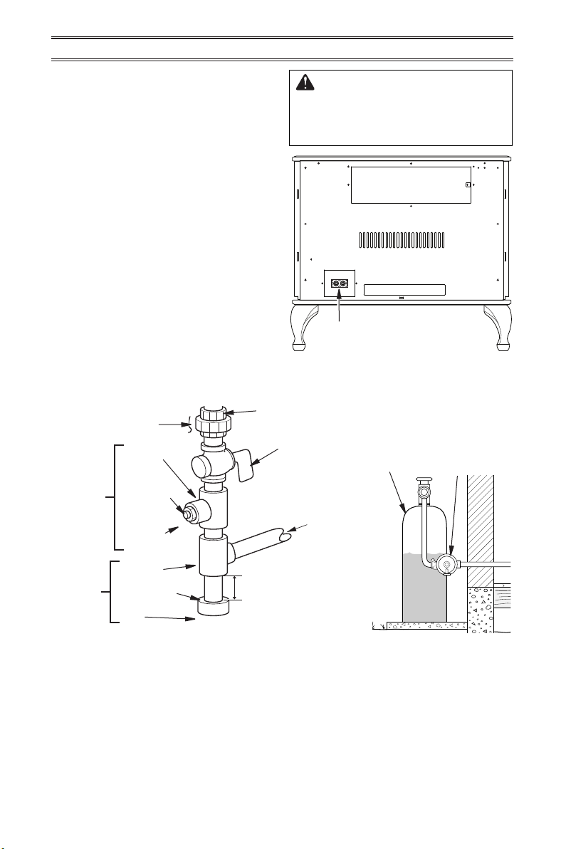
Figure 10 - Gas Connection
Figure 9 - Gas Regulator Location and
Gas Line Access Into Stove Cabinet
* Purchase the optional CSA design-certied equipment
shutoff valve from your dealer.
Apply pipe joint sealant lightly to male threads.
This will prevent excess sealant from going
into pipe. Excess sealant in pipe could result
in clogged heater valves.
For propane installations, the installer must
supply an external regulator. The external
regulator will reduce incoming gas pressure.
You must reduce incoming gas pressure
to between 11" and 14" of w.c. If you do
not reduce incoming gas pressure, heater
regulator damage could occur. Install external
regulator with the vent pointing down as
shown in Figure 11. Pointing the vent down
protects it from freezing rain or sleet.
For both gas types, install sediment trap in
supply line as shown in Figure 10. Place
sediment trap where it is within reach for
cleaning. Place sediment trap where trapped
matter is not likely to freeze. A sediment trap
traps moisture and contaminants. This keeps
them from going into heater controls. If sedi-
ment trap is not installed or is installed wrong,
heater may not run properly.
Figure 11 - External Regulator
with Vent Pointing Down
External
Regulator with
Vent Pointing
Down
Propane
Supply Tank
Equipment
Shutoff Valve
Ground
Joint Union
3/8" NPT
Pipe Nipple
Tee Joint
Reducer
Bushing to
1/8" NPT
1/8" NPT
Plug Tap
Test Gauge
Connection*
Sediment
Trap
Tee Joint
Pipe Nipple
Gap
3" Minimum
Natural Gas
From Gas Meter
(5" W.C.** to
9.5" W.C.
Pressure)
Propane
From External
Regulator
(11" W.C.**
to 14" W.C.
Pressure)
WARNING: Test all gas piping
and connections for leaks after
installing or servicing. Correct
all leaks at once (see page 14).
Gas Inlet Regulator
Connection
Loading ...
Loading ...
Loading ...