Loading ...
Loading ...
Loading ...
5
CAUTION
Check that the control cables are not being
strained while folding and unfolding the
handle� Permanent kinks will make the
controls difficult to operate�
TIPPING THE MOWER SAFELY FOR STORAGE
OR INSPECTION.
Tilting the mower—Drain fuel, then tilt the
mower with the spark plug uppermost�
Remove the spark plug lead�
CAUTION
ASSEMBLING THE
MOWER
Please refer to the following sections when
preparing the mower for its first use.
• Fitting the handle
• Preparing the Engine
• Assembling the catcher
NOTE - The left and right sides of the mower are
referred to as viewed from the operating position
behind the handle.
FITTING THE HANDLE
In some cases the handle may be completely
detached from the mower body although the
upper handle may be connected by the throttle
control cable. Carefully remove the mower and
handles from the box together to avoid damaging
the throttle control.
ASSEMBLING THE ‘SCREW LOCK’ HANDLE.
The lower handle is fitted to the mower using the
four bolts located in the handle brackets, two on
each side, ‘A’ in the drawing below. To bolt the
lower handle to the mower fit the bolts through
the lower handle then fit the handle to the mower
body and tighten the nuts on the outside of the
mounting brackets using a 13mm A/F socket or
spanner.
Now attach the upper handle to the lower handle.
420MM MODELS
The 420mm model is shipped with the handle
completely detached from the mower body
although the upper handle may be connected by
the throttle control cable to the engine. Carefully
remove the mower and handles from the box
together to avoid damaging the throttle control
and cable.
ASSEMBLING THE LOWER HANDLE
The lower handle stubs are fitted to the mower
using the four bolts located in the handle
brackets, two on each side, ‘B’ in the drawing
below. To bolt the lower handle to the mower fit
the bolts through the lower handle then fit the
handle to the mower body and tighten the nuts
on the inside of the housing using a 13mm A/F
socket or spanner.
B
Now attach the upper handle to the lower handle
stubs.
Take care not to rotate the handle before fitting
it, as this will tangle the control cable(s)�
CAUTION
Fit the two long bolts through the holes in the
lower handle from the inside with the round heads
snug against the tube. Fit the holes in the upper
handle over the two long bolts. Make sure that
the throttle control is located on the right hand
side. Attach the plastic knob to the outside of the
lower handle bolt as shown below and tighten by
hand until the upper handle is locked in position.
ASSEMBLING THE ‘CAM LOCK’ HANDLE.
Most of these models are fully assembled when
packed, so all that is needed is to remove
them from the carton, swing the handle to the
operating position and lock the handle lever(s).
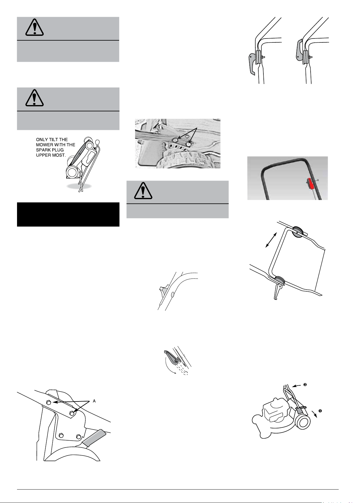
THE CAMLOCK HANDLES ON SOME
MOWERS ARE REVERSED FOR SHIPPING.
To turn them around unwind the nut to the end of
the thread with a 13mmA/F spanner/socket, pull
the camlock handle outwards and rotate it 180
o
.
Retighten the nut until the handle locks firmly in
place and it does not change position when in
use.
The correct locked
position after refitting�
Locked position
when Shipped�
FITTING THE THROTTLE CONTROL
In some cases the throttle control may be
completely detached from the upper handle.
Using the bolt and nut attached to the throttle
control, attach the throttle on LH side of the
upper handle (inside the handle).
THE ‘ERGO’ HANDLE
CAM LOCK
LEVER
ADJUST
HEIGHT
The ‘Ergo’ handle can be adjusted to your
preferred height. Simply release both cam lock
levers, move the upper handle to the height
required and re-clamp the cam locks. Where the
mower has screw type locks, wind the knobs
firmly clockwise to lock the handle.
ERGO SHIFT
Some handles can be rotated forward to
give easy access to the rear flap. Depress the
foot lever u and push the handle until you feel
resistance— in a near vertical position v. The
handle can be moved back to the mowing
position without using the foot lever.
CONTRACTOR COMMERCIAL MODELS
ADJUSTING THE HANDLE HEIGHT
Loading ...
Loading ...
Loading ...