Loading ...
Loading ...
Loading ...
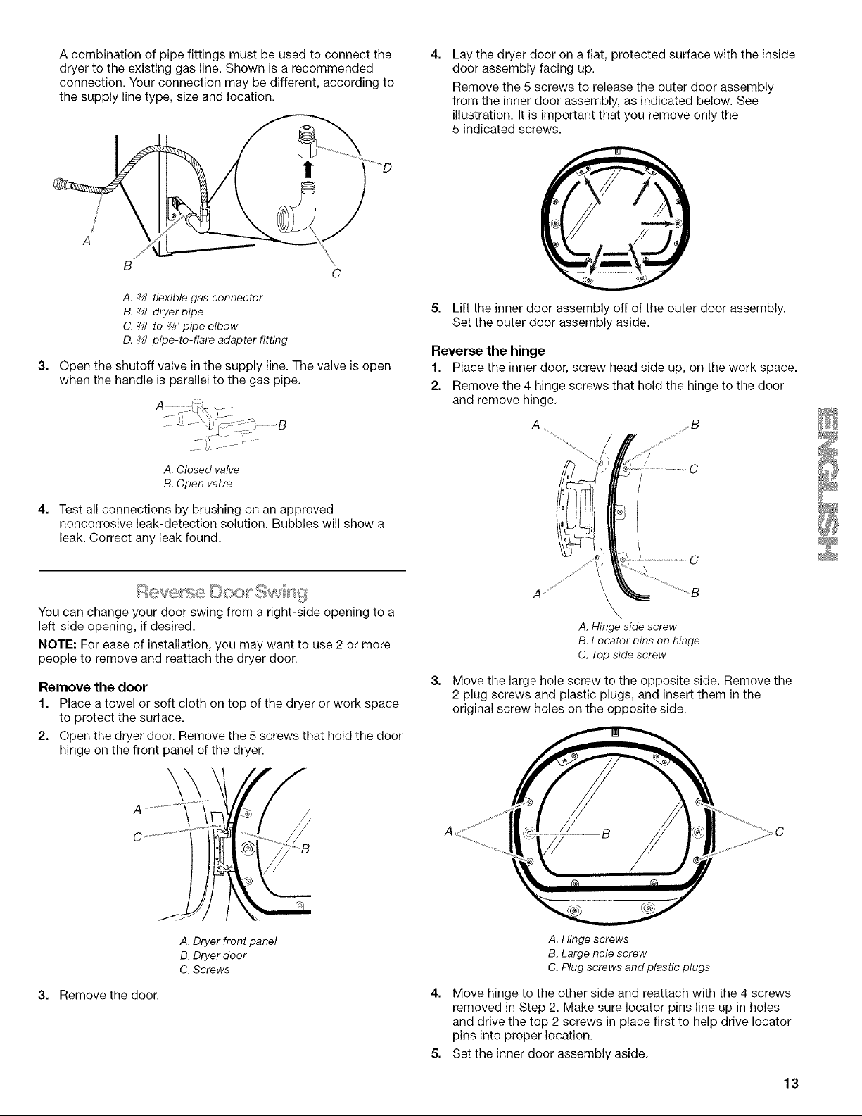
A combination of pipe fittings must be used to connect the
dryer to the existing gas line. Shown is a recommended
connection. Your connection may be different, according to
the supply line type, size and location.
!
3.
4.
A. _" flexible gas connector
B. _" dryer pipe
C. _" to _" pipe elbow
D. _" pipe-to-flare adapter fitting
Open the shutoff valve in the supply line. The valve is open
when the handle is parallel to the gas pipe.
A. Closed valve
B. Open valve
Test all connections by brushing on an approved
noncorrosive leak-detection solution. Bubbles will show a
leak. Correct any leak found.
You can change your door swing from a right-side opening to a
left-side opening, if desired.
NOTE: For ease of installation, you may want to use 2 or more
people to remove and reattach the dryer door.
Remove the door
1. Place a towel or soft cloth on top of the dryer or work space
to protect the surface.
2. Open the dryer door. Remove the 5 screws that hold the door
hinge on the front panel of the dryer.
4.
Lay the dryer door on a flat, protected surface with the inside
door assembly facing up.
Remove the 5 screws to release the outer door assembly
from the inner door assembly, as indicated below. See
illustration. It is important that you remove only the
5 indicated screws.
5. Lift the inner door assembly off of the outer door assembly.
Set the outer door assembly aside.
Reverse the hinge
1. Place the inner door, screw head side up, on the work space.
2. Remove the 4 hinge screws that hold the hinge to the door
and remove hinge.
A
3.
\
C
A _'_
A. Hinge side screw
B. Locator pins on hinge
C. Top side screw
Move the large hole screw to the opposite side. Remove the
2 plug screws and plastic plugs, and insert them in the
original screw holes on the opposite side.
3. Remove the door.
A. Dryer front panel
B. Dryer door
C. Screws
A. Hinge screws
B. Large hole screw
C. Plug screws and plastic plugs
4. Move hinge to the other side and reattach with the 4 screws
removed in Step 2. Make sure Iocator pins line up in holes
and drive the top 2 screws in place first to help drive locater
pins into proper location.
5. Set the inner door assembly aside.
13
Loading ...
Loading ...
Loading ...