SE ARS
OWNER'S
MANUAL
MODELNO.
390.305001
390.304790
390.305790
CAUTION:
Read and Follow
All Safety Rulesand
Operating Instructions
Before FirstUseof
ThisProduct.
Save ThisManual Far
FutureReference.
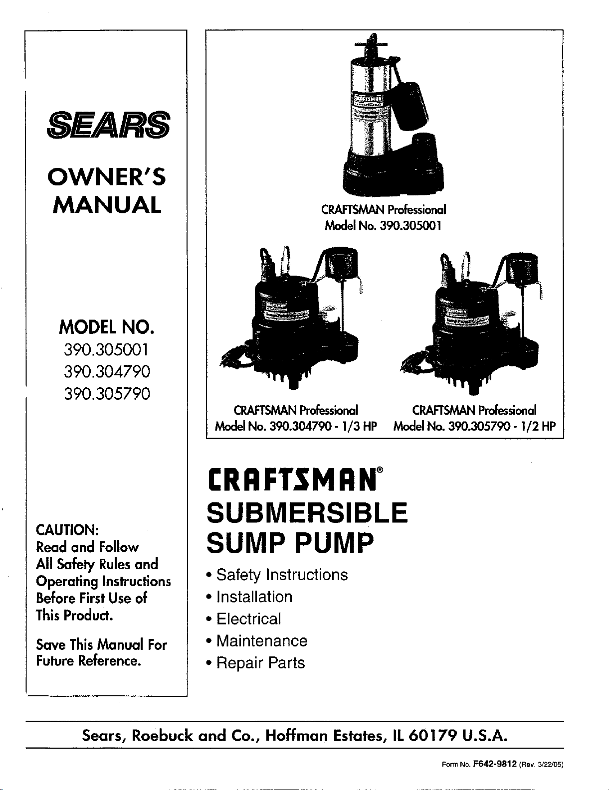
CRAFTSMANProfessional
Model No. 390.305001
CRAFTSMANProfessional CRAFTSMANProfessional
Model No. 390.304790 - 1/3 HP Model No. 390.305790 - 1/2 HP
I:RRFTJ;MRN
SUBMERSIBLE
SUMP PUMP
• Safety Instructions
• Installation
• Electrical
• Maintenance
• Repair Parts
Sears, Roebuck and Co., Hoffman Estates, IL 60179 U.S.A.
FormNo.F642-9812 (Rev.3/22/05)
CONTENTS
INTRODUCTION/WARRANTY ......................................... 2
SAFETY ........................................................................... 2-3
INSTALLATION ............................................................... 5-4
OPERATION ...................................................................... 4
ELECTRICAL ................................................................... 4-5
MAINTENANCE ................................................................. 5
SERVICE .......................................................................... 6-7
PARTS ................................................................................ 8
INTRODUCTION
Please read our instructions before you install and use your
new pump; this will help you obtain full value and good ser-
vice from it. It will also help you avoid needless service costs
that result from causes we cannot control and cannot cover
in our warranty.
GENERAL SAFETY INFORMATION
Carefully read and follow all safety instructions in this
manual or on pump.
This is the safety alert symbol When you see this
symbol on your pump or in this manual, look for one
of the following signal words and be alert to the potential
for personal injury!
_ warns about hazards that will cause serious
personal injury, death or major property damage ff ignored.
['_ WAFININGIwarns about hazards that will or can cause se-
rious personal injury, death or major property damage if ig-
nored.
It, CAUTIONIwarn s about hazards that will or can cause
minor personal injury or property damage if ignored.
The word NOTICE indicates special instructions which are
important but not related to hazards.
Electrically powered surnp pumps normally give many years
of trouble-free service when correctly installed, maintained,
and used. However, unusual circumstances (interruption of
power to the pump, dirt/debris in the sump, flooding that ex-
ceeds the pump's opacity, electrical or mechanical failure in
the pump, etc.) may prevent your pump from functioning
normally. To prevent possible water damage due to flooding,
consult your local Sears store about installing a secondary
sttmp pnmp or a DC backup sump pinup. See "Service', Page
6, for information about common sump pump problems and
remedies.
1. To avoid risk of serious bodily injury and property dam-
age, read safety instructions carefully before installing
pump.
2. Follow local and/or national plumbing and electrical
codes when installing pump.
3. [&WARNING]To avoid fatal shocks, proceed as fol-
lows if pump needs servicing:
A.Disconnect power to pump outlet box before
pulling pump cord plug. After plug is pulled, let
pump cool for 20 minutes before attempting to work
on it. Modern motors may operate at high tempera-
HIFeS.
B. Take extreme care when changing fuses. To re-
duce the chance of fatal electrical shocks, DO NOT
stand in water or put your finger in the fuse socket.
C. Ground the electrical outlet box.
D.Use only an individual branch circuit with a
Ground Fault Circuit Interrupter (GFCD protected
grounded outlet for cord plug.
2
SAFETY / INSTALLATION
4. Never rim pump dry. To do so can damage internal
parts, overheat the pump (which can cause burns to peo-
ple handling or servicing the pump), and will void the
warranty_.
5. DO NOT attempt to oil the pump motor. A special oil has
been put into the motor housing at the factory; use of any
other oll will void the warranty and could damage the
pump.
6. This pump is recommended for use in permanent instal-
lations only. This pump has not been invenstigated for use
in swimming pool areas.
7. Know the pump application, limitations, and potential
hazards. Not for use with salt water or brine.
[_'WARNING]Do not use in explosive atmospheres.
Pump water only with this pump. Failure to follow
this warning can result in personal injury and!or
property damage.
8. Release aU pressure within the system before servicing
any component.
9. Drain water from the system before servicing.
10. Secure the discharge line before starting the pump. An un-
secured discharge line will whip, possible causing per-
sonal injury and/or property damage.
11. Periodically inspect pump and system components. Perform
routine maintenance as required (See MAINTENANCE).
12. Provide a means of pressure relief for pumps whose dis-
charge line can be shut-off or obstructed.
13. Personal Safety:
a: Wear safety glasses at all times when working with
pumps.
b. Keep work area clean, uncluttered and properly
lighted - replace all unused tools and equipment.
c. Keep visitors at a safe distance from the work area.
d. Make workshop child-proof - with padlocks, master
switches, and by removing starter keys.
14. This equipment is ordy for use on 115 volt (single phase)
and is equipped with an approved 3-conductor cord and
3-prong, grounding-type plug.
[_WARNING]To reduce the risk of electric shock,
pull plug before servicing. This pump has not been
investigated for use in swimming pool areas. This
pump is supplied with a grounding conductor and
grounding-type attachment plug. Be certain that it
is connected only to a properly grounded ground-
ing-type receptacle.
Where a 2-prong wall receptacle is encountered, it
must be replaced with a properly grounded 3-prong
receptacle installed in accordance with the National
Electrical Code and local codes and ordinances.
15.Protect electrical cord from sharp objects, hot surfaces,
oil, and chemicals. Avoid kinking the cord. Replace or re-
pair damaged or worn cords immediately.
16. Do not handle a pump or pump motor with wet hands or
when standing on a wet or damp surface, or in water.
IA WARNINGjR isk of electric shock. If your basement
1
has water or moisture on the floor, do not walk on wet
area until all power has been turned off. If shut-off
box is in basement, call the electric company to shut-
off service to the house, or call your local fire depart-
ment for instructions. Remove pump and repair or
replace. Failure to follow this warning can result in
fatal electrical shock.
ADDITIONAL INSTALLATION
MATERIALS (Purchase Separately)
Sttmp Pump Hose Kit, SEARS Stock No. 27909, containing
24' (7.3M) of 1-1/4" flexible plastic pipe, 1-1/4" plastic
adapter and stainless steel clamp. We recommend a Check
Valve, SEARS Stock No. 2789 or 2792.
THE SUMP
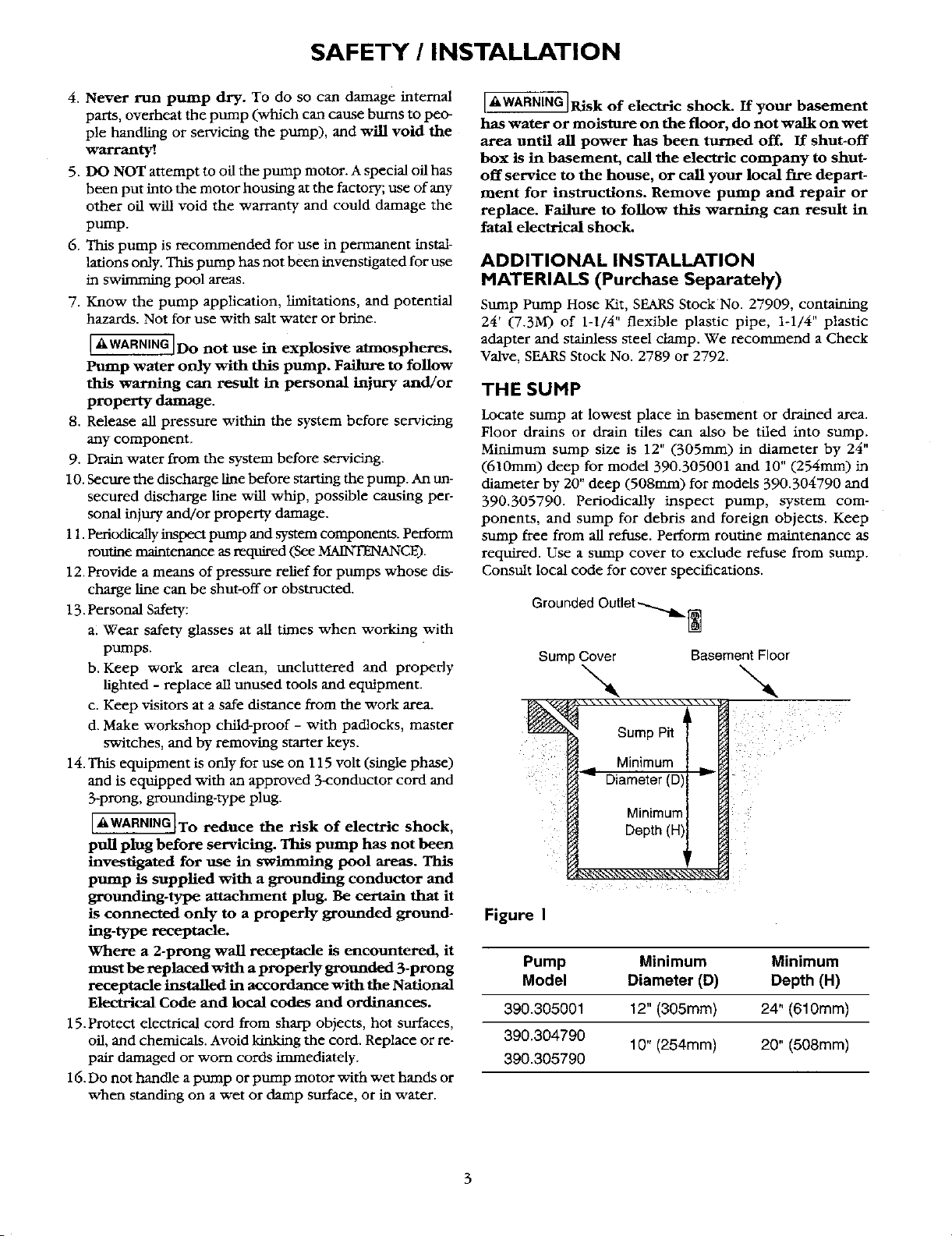
Locate sump at lowest place in basement or drained area.
Floor drains or drain tiles can also be tiled into sump.
Minimum sump size is 12" (305ram) in diameter by 24"
(610mm) deep for model 390.305001 and 10" (254mm) in
diameter by 20" deep (508ram) for models 390.304790 and
390.305790. Periodically inspect pump, system com-
ponents, and sump for debris and foreign objects. Keep
sump free from all refuse. Perform routine maintenance as
required. Use a sump cover to exclude refuse from sump.
Consult local code for cover specifications.
Grounded Outlet-_[_
Sump Cover Basement Floor
-.., -..,
\\\_.\ \ \\-_ \ \\_.\\\ _\
Bump Pit
Minimum
_ Diameter (D', _
Minimum
Depth (HI
Figure I
Pump Minimum Minimum
Model Diameter (D) Depth (H)
390.305001 12" (305ram) 24" (610mm)
390.304790
10" (254mm) 20" (508mm)
390.305790
INSTALLATION / OPERATION / ELECTRICAL
PUMP INSTALLATION
Set the pump on the bottom of the sump, making sure that
it sits solidly and is level. Be sure there is enough space
around the pump to allow the switch free movement as the
sump water level changes. Do not install the pump on clay,
earth, or sand surface.
IA CAUTION]Risk of flooding. If a flexible discharge
hose is used, pump may move around in sump when
motor starts. If it moves farenough so that the switch hits
the side of the sump, the svdtch may stick and prevent
pump from starting. Make sure that pro'rip is secured so that
it cannot walk around in sump.
Hose Kit No. 27909 can be used as the discharge pipe. Run
the discharge pipe to the nearest sewer outlet or other point
of disposal. Use the most direct route and the fewest rums
and elbows possible.
Use Teflon tape to seal threads in plastic pipe. Hand tighten
only.
NOTE: To avoid backflow into sump when pump shuts off,
install a Check Valve, SEARSStock No. 2789, in threaded dis-
charge port of pump. A SEARSNo. 2789 Check Valve is con-
structed with an anti-airlock hole. Ifyou use a SEARSNo. 2792
or any other check valve, drill a 1/8" hole in the discharge pipe
just above the pump discharge port and below the Check
Valve to prevent pump from airlocking.
Make sure the air-bleed hole is down inside the sltmp so that
it does not rim water on the basement floor when the pump
is running.
AUTOMATIC FLOAT SWITCH
INSTALLATION AND OPERATION
Your SEARS Model 390.305001 Submersible Drainer comes
with the automatic float switch mounted on the motor hous-
ing ready for operation. Tether length is factory set at 3"
(76ram). Do not change tether length. See Page 7 for verti-
cal float switch instructions.
[AWARNING] Risk of electric shock. Always disconnect
the pump and switch from the electrical power source
before doing any maintenance!
Follow instructions below to install pump with factory
mounted switch:
1. Be sure automatic float can swing freely through its entire
arc without interference from pump, piping, sump wall
or any other object.
2. Plug the automatic switch cord into a properly grounded
outlet (see "Electrical Connections", Page 4). Plug the
pump power cord into the back of the switch plug.
3. Test the installation by adding water to the sump pit until
pump operates normally as folJows:
A. When sump is dry, the watertight automatic float
switch is hanging in a downward position and the
pump is off.
B.As water comes into the sump, the automatic float
switch rises to an upward position and the pump starts.
C.Water will continue to be pumped until the float switch
is hanging in the downward position again, when
pump vdll stop.
DO NOT ALLOW PUMP TO RUN DRY_.
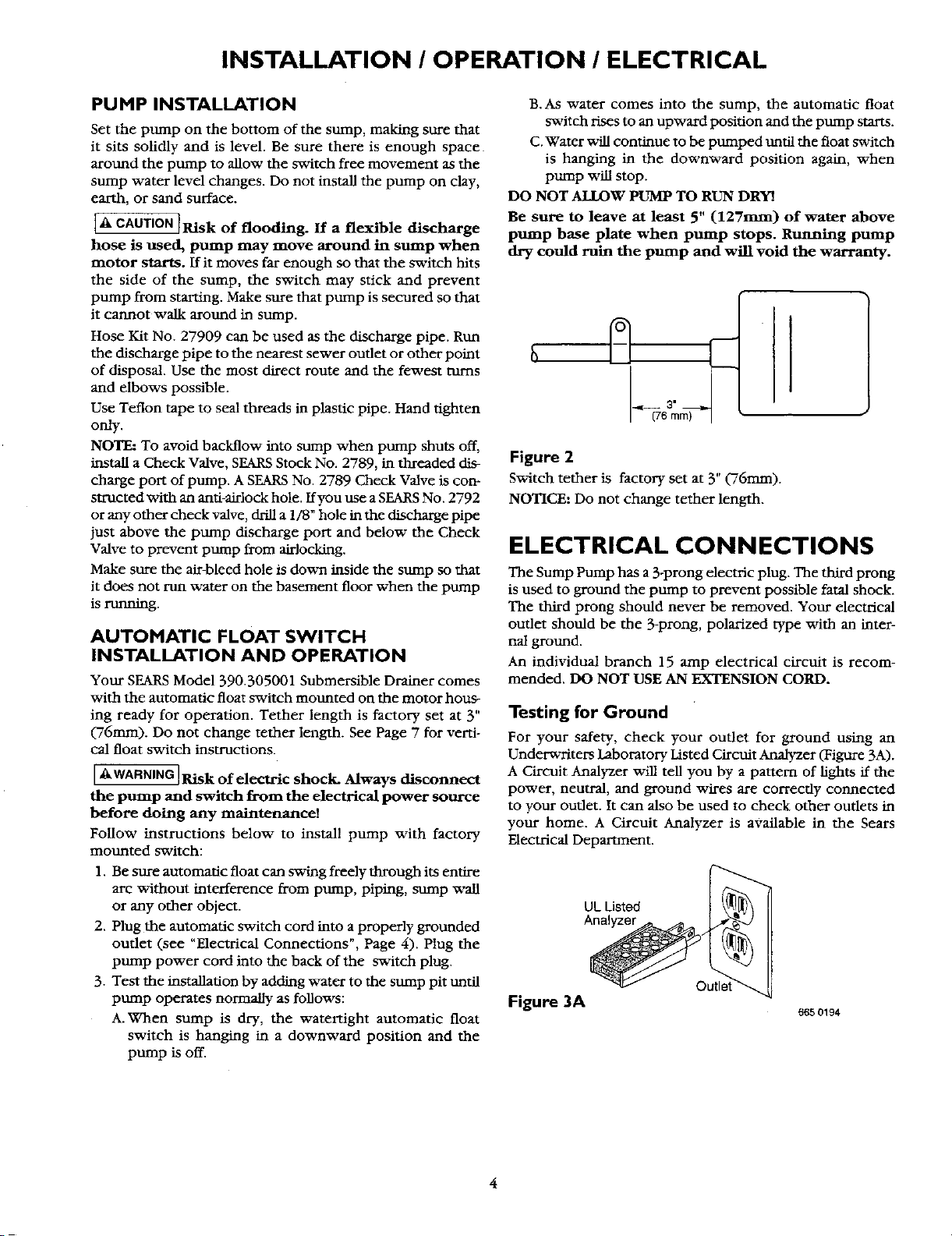
Be sure to leave at least 5" (127mm) of water above
pump base plate when pump stops. Running pump
dry could ruin the pump and will void the warranty.
Figure 2
Switch tether is factory set at 3" ('76ram).
NOTICE: Do not change tether length.
ELECTRICAL CONNECTIONS
The Sump Pump has a 3-prong electric plug. The third prong
is used to ground the pump to prevent possible fatal shock.
The third prong should never be removed. Your electrical
outlet should be the 3-prong, polarized type with an inter-
nal ground.
An individual branch 15 amp electrical circuit is recom-
mended. DO NOT USE AN EXTENSION CORD.
Testing for Ground
For your safety, check your outlet for ground using an
Underwriters Laboratory Listed Circuit Analyzer (Figure 3A).
A Circuit Analyzer v_fll tell you by a pattern of lights ff the
power, neutral, and ground wires are correctly connected
to your outlet. It can also be used to check other outlets in
your home. A Circuit Analyzer is available in the Sears
Electrical Department.
UL Listed
Analyzer ._._ _
Outlet_
Figure 3A
665 0194
ELECTRICAL / MAINTENANCE
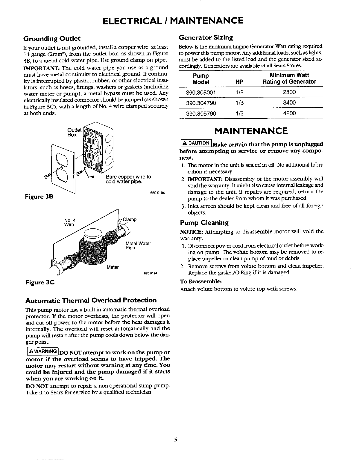
Grounding Outlet
If your outlet is not grounded, install a copper wire, at least
14 gauge (2mmZ), from the outlet box, as shown in Figure
3B, to a metal cold water pipe. Use ground clamp on pipe.
IMPORTANT: The cold water pipe you use as a ground
must have metal continuity to electrical ground. If continu-
ity is interrupted by plastic, rubber, or other electrical insu-
lators; such as hoses, fittings, washers or gaskets (including
water meter or pump), a metal bypass must be used. Any
electrically insulated connector should be jumped (as shown
in Figure 3C), with a length of No. 4 wire clamped securely
at both ends.
Outlet
Figure 3B
No. 4 31amp
Wire
MetalWater
Pipe
Figure 3C
Meter
670 0194
Automatic Thermal Overload Protection
This pump motor has a built-in automatic thermal overload
protector. If the motor overheats, the protector will open
and cut off power to the motor before the heat damages it
internally. The overload will reset automatically and the
pump will restart after the pump cools down below the dan-
ger point.
[_kWARNING] DO NOT attempt to work on the pump or
motor if the overload seems to have tripped. The
motor may restart without warning at any time. You
could be injured and the pump damaged if it starts
when you are working on it.
DO NOT attempt to repair a non-operational surnp pump.
Take it to Sears for service by a qualified technician.
Generator Sizing
Below is the minimum Engine-Generator Watt rating required
to power this pump motor. Any additional loads, such as lights,
must be added to the listed load and the generator sized ac-
cordingly. Generators are available at all Sears Stores.
Pump Minimum Watt
Model HP Rating of Generator
390.305001 1/2 2800
390.304790 1/3 3400
390.305790 1/2 4200
HAINTENANCE
_Make certain that the pump is unplugged
before attempting to service or remove any compo-
nent.
1. The motor in the unit is sealed in oil. No additional lubri-
cation is necessary.
2. IMPORTANT: Disassembly of the motor assembly will
void the warranty. It might also cause internal leakage and
damage to the unit. If repairs are required, return the
pump to the dealer from whom it was purchased.
3. Inlet screen should be kept clean and free of all foreign
objects.
Pump Cleaning
NOTICE: Attempting to disassemble motor will void the
warranty.
1. Disconnect power cord from electrical outlet before work-
hag on pump. The volute bottom may be removed to re-
place impeller or clean pump of mud or debris.
2. Remove screws from volute bottom and clean impeller.
Replace the gasket/O-Ring if it is damaged.
To Reassemble:
Attach volute bottom to volute top with screws.
SERVICE / SPECIFICATIONS
General
[AWARNING]RJsk of electric shock. When servicing
pump always disconnect power to electrical outlet
and remove pump electric cord fi'om outlet.
1. if'pump does not operate:
a. Check for loose plug at electric outlet.
b. Check for blown fuses or tripped circuit breakers at
fuse box/(trcult breaker box.
c. Be sure nothing interferes with action of automatic
float switch.
d. If a, b, and c above check OK, plug in a Eght that you
know works. If it lights, take your pump to Sears for
service. If it doesn't light, the electrical circuit is faulty;
consult a licensed electrician.
2. Pump starts, but blows fuses/trips circuit breakers:
After disconnecting power to pump, remove the screen
and shield from the bottom of the pump and make sure
that the impeUer turns freely. Remove any debris ob-
structing impeller. If pump still does not operate cor-
rectly, return it to your nearest Sears Service Department
for repairs.
3. Pump runs, but does not empty sump:
a. Clean pump intake screen.
b. Water may be entering sump faster than the pump can
discharge it.
c. Be sure vertical distance from pump discharge outlet
to discharge pipe outlet does not exceed maximum
vertical pumping distance shown in "Specifications,"
below.
d. Be sure discharge pipe is not plugged or frozen.
TEATHERED SWITCH REPLACEMENT
NOTICE: Teathered float must be able to swing through its
complete arc without interference from sidewall of sump,
plumbing or any other object.
1. Remove pump power cord from switch plug.
2. Remove tether clamp screw and slide cord from clamp.
3. Insert new cord in tether clamp. Put the clamp at the
same distance from the float that it was on the old switch.
4. Tighten tether clamp screw.
5. Check sump pump operation by fiUing sump with water
and observing operation through one complete cycle.
_ Failure to check installation with water
in sump can lead to improper operation, premature
pump failure and flooding.
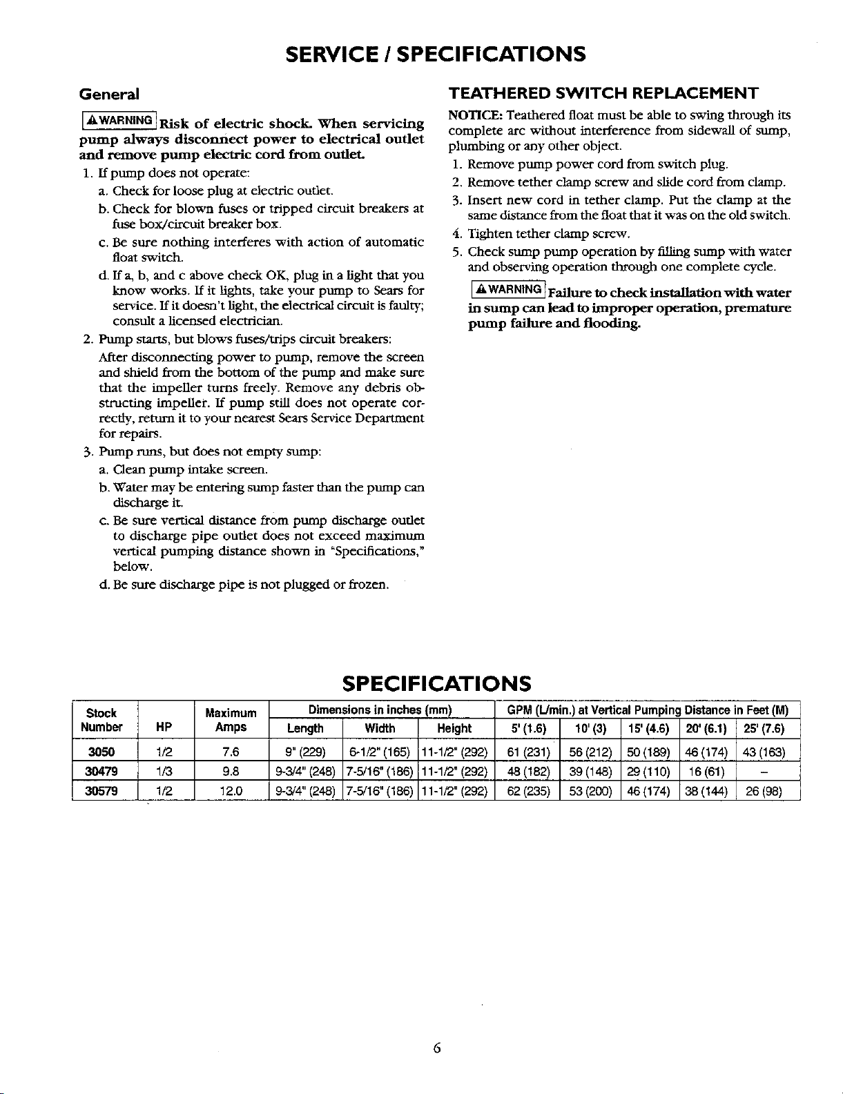
Stock Maximum
Number HP Amps
3050 1/2 7.6
30479 1/3 9.8
3O579 1/2 12.0
SPECIFICATIONS
Dimensions in inches(mm)
Length Width Height
9" (229) 6-1/2" (165) 11-1/2" (292)
9,-3/4"(248) 7-5/16" (186) 11-1/2" (292)
9-3/4" (248) 7-5/16" (186) 11-1/2" (292)
GPM (L/rain.) at Vertical Pumping Distance in Feet(M)
5' (1.6) 10' (3) 15' (4.6) 20' (6.1) 25' (7,6)
61(231) 56(212) 50(189) 46(174) 43(163)
48(182) 39(148) 29(110) 16(61)
62(235) 53(200) 46(174) 38(144) 26(98)
SERVICE
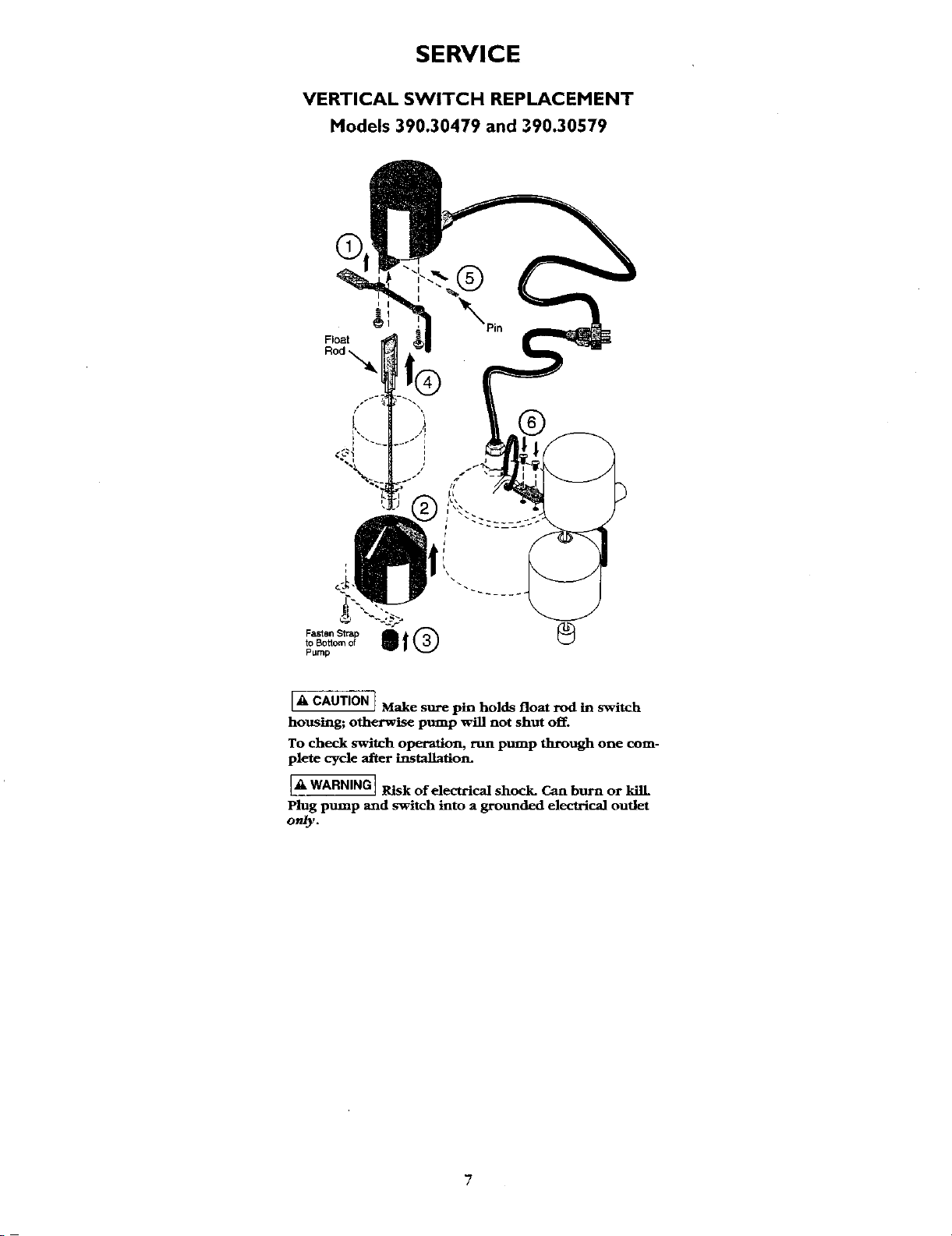
VERTICAL SWITCH REPLACEMENT
Models 390.30479 and 390.30579
®
®
A j Make sure pin holds float rod in switch
CAUTION
housing; otherwise pump will not shut off.
To check switch operation, run pump through one com-
plete cycle after installation.
A WARNINGj Risk of electrical shock. Can burn or kilL
]
Plug puLmp and switch into a grounded electrical outlet
only.
7
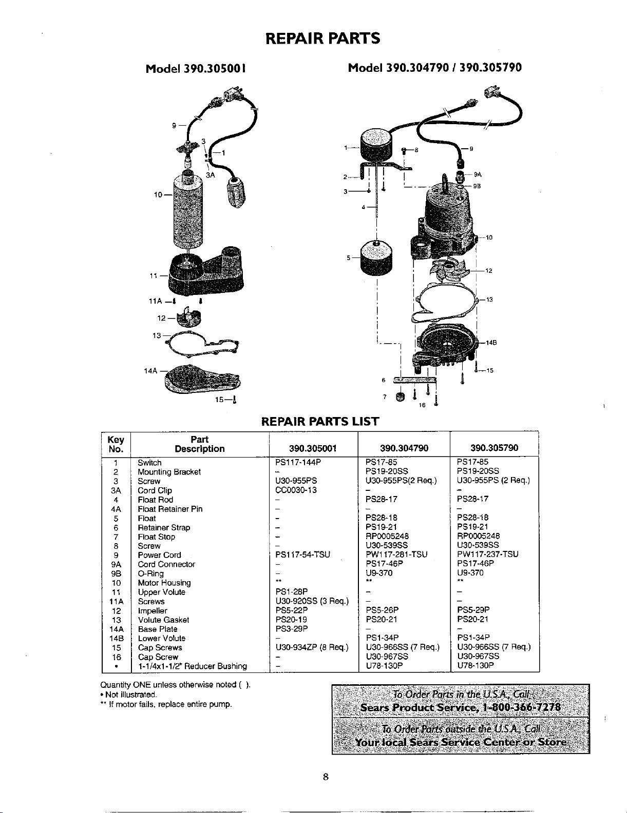
REPAIR PARTS
Model 390.305001
Model 390.304790 / 390.305790
1i
2--
I
3_
4--
!
-- 9B
11--
11A --I l
12--
tS--A
I
I
I
i
i....
I
I
REPAIR PARTS LIST
Key Part
No. Description
1 Switch
2 Mounting Bracket
3 Screw
3A Cord Clip
4 Float Rod
4A Float Retainer Pin
5 Float
6 Retainer Strap
7 Float Stop
8 Screw
9 Power Cord
9A Cord Connector
9B O-Ring
10 Motor Housing
11 Upper Volute
11A Screws
12 Impeller
13 Volute Gasket
14A Base Plate
14B Lower Volute
15 Cap Screws
16 Cap Screw
1-1/4x1-1/2" Reducer Bushing
390.305001
PS117-144P
U30-955PS
CC0030-13
PS117-54-TSU
390.304790
PS17-85
PS19-20SS
U30-955PS(2 Req.)
PS28-17
PS28-18
PS19-21
RP0005248
U30o539SS
PW117-281-TSU
PS17-46P
390.305790
PS17-85
PS19-20SS
U30-955PS (2 Req.)
PS28-17
PS28_18
PS19-21
RP0005248
U30-539SS
PW117-237-TSU
PS17-46P
PS1-28P
U30-920SS (3 Rap.)
PS5-22P
PS20-19
PS3-29P
U30-934ZP (8 Req.)
U9-370
PS5-26P
PS20-21
PS1-34P
U30-966SS (7 Req.)
U30-967SS
U78-130P
U9-370
PS5-29P
PS20-21
PSI-34P
U30-966SS (7 Req.)
U30-967SS
U78-130P
Quantity ONE unless otherwise noted ().
• Not illustrated.
** If motor fails, replace entire pump.

9
Your Home
For repair-in your home-of all major brand appliances,
lawn and garden equipment, or heating and cooling systems,
no matter who made it, no matter who sold it!
For the replacement parts, accessories and
owner's manuals that you need to do-it-yourself.
For Sears professional installation of home appliances
and items like garage door openers and water heaters.
1-800-4-MY-HOME ® (1-800-469-4663)
Call anytime, day or night (U.S.A. and Canada)
www.sears.com www.sears.ca
Our Home
For repair of carry-in items like vacuums, lawn equipment,
and electronics, call or go on-line for the location of your nearest
Sears Parts & Repair Center.
1-800-488-1222
Call anytime, day or night (U.S.A. only)
www.sears.com
To purchase a protection agreement (U.S.A.)
or maintenance agreement (Canada) on a product serviced by Sears:
1-800-827-6655 (U.S.A.) 1-800-361-6665 (Canada)
Para pedir servicio de reparaci6n
a domicilio, y para ordenar piezas:
1-888-SU-HOGAR _
(1-888-784-6427)
Au Canada pour service en fran_ais:
1-800-LE-FOYER M°
(1-800-533-6937)
www.sears.ca
TM 9M
® Registered Trademark / Trademark / Service Mark of Sears, Roebuck and Co.
® Mama Registrada / TMMama s_de Fabrica / Marca de Servicio de Sears, Roebuck and Co.
_c Marque de commerce / MOMarque d6pos6e de Seam, Roebuck and Co. © Sears, Roebuckand Co.