USER GUIDE & SERVICE MANUAL
5 Class
●
UHWD524
●
24” Dual Zone Wine Captain
®
USER GUIDE & SERVICE MANUAL
u-line.com
Table of Contents
Intro
Safety
Safety and Warning
Disposal And Recycling
Installation
Environmental Requirements
Electrical
Cutout & Product Dimensions
Side by Side Installation
Anti-Tip Bracket
General Installation
Grille Installation
Door Swing
Door Adjust
Interior Adjustments
Maintenance
Cleaning
Cleaning Condenser
Extended Non-Use
Operating Instructions
First Use
Control Operation
Airflow and Product Loading
Service
Troubleshooting
Product Liability
Warranty Claims
Warranty
USER GUIDE
Introduction
u-line.com
WELCOME TO U-LINE
Congratulations on your U-Line purchase. Your product comes from a company with over five decades of premium modular
ice making, refrigeration, and wine preservation experience. U-Line continues to be the American leader, delivering versatility
and flexibility for multiple applications including residential, light commercial, outdoor and marine use. U-Line’s complete
product collection includes Wine Captain
®
Models, Beverage Centers, Clear Ice Machines, Nugget Ice Machines, Crescent Ice
Makers, Glass & Solid Door Refrigerators, Drawer Models, Freezers, Combo
®
Models, and more.
U-Line has captivated those with an appreciation for the finer things with exceptional functionality, style, inspired innovations
and attention to even the smallest details. We are known and respected for our unwavering dedication to product design,
quality and selection. U-Line is headquartered in Milwaukee, Wisconsin and has shipped product to five continents for over
two decades and is proud to have the opportunity to ship to you.
PRODUCT INFORMATION
Looking for additional information on your product? User Guides, Spec Sheets, CAD Drawings, Compliance Documentation,
and Product Warranty information are all available for reference and download at u-line.com.
PROPERTY DAMAGE / INJURY CONCERNS
In the unlikely event property damage or personal injury is suspected related to a U-Line product, please take the following
steps:
1. U-Line Customer Care must be contacted immediately at +1.800.779.2547.
2. Service or repairs performed on the unit without prior written approval from U-Line is not permitted. If the unit has been
altered or repaired in the field without prior written approval from U-Line, claims will not be eligible.
GENERAL INQUIRIES
U-Line Corporation
8900 N. 55th Street
Milwaukee, Wisconsin 53223 USA
Monday - Friday 8:00 am to 4:30 pm CST
T: +1.414.354.0300
F: +1.414.354.7905
Email: sales@u-line.com
u-line.com
SERVICE & PARTS ASSISTANCE
Monday - Friday 8:00 am to 4:30 pm CST
T: +1.800.779.2547
F: +1.414.354.5696
Service Email: onlineservice@u-line.com
Parts Email: onlineparts@u-line.com
CONNECT WITH US
Designed, engineered and assembled in WI, USA
3
USER GUIDE
u-line.com
Safety and Warning
Safety and Warning
NOTICE
Please read all instructions before installing,
operating, or servicing the appliance.
Use this appliance for its intended purpose only and follow
these general precautions with those listed throughout this
guide:
SAFETY ALERT DEFINITIONS
Throughout this guide are safety items labeled with a
Danger, Warning, or Caution based on the risk type:
Danger means that failure to follow this safety
statement will result in severe personal injury or
death.
Warning means that failure to follow this safety
statement could result in serious personal injury
or death.
Caution means that failure to follow this safety
statement may result in minor or moderate
personal injury, property, or equipment damage.
This unit contains R600a (Isobutane) which is a
ammable hydrocarbon. It is safe for regular
use. Do not use sharp objects to expedite
defrosting. Do not service without consulting the
“R600a specications” section included in the
User Guide. Do not damage the refrigerant
circuit.
Service must be done by factory authorized
service personnel. Any parts shall be replaced
with like components. Failure to comply could
increase the risk of possible ignition due to
incorrect parts or improper service.
CALIFORNIA PROPOSITION 65
This product contains chemicals known to the
state of California to cause cancer and birth
defects or other reproductive harm.
www.P65warnings.CA.gov
This equipment is to be installed with adequate
backow protection to comply with applicable
federal, state and local codes.
DANGER
!
DANGER
!
WARNING
!
CAUTION
!
CAUTION
!
WARNING
!
4
USER GUIDE
u-line.com
Disposal and Recycling
Disposal and Recycling
RISK OF CHILD ENTRAPMENT. Before you throw
away your old refrigerator or freezer, take o
the doors and leave shelves in place so children
may not easily climb inside.
If the unit is being removed from service for disposal,
check and obey all federal, state, and local regulations
regarding the disposal and recycling of refrigeration
appliances, and follow these steps completely:
1. Remove all consumable contents from the unit.
2. Unplug the electrical cord from its socket.
3. Remove the door(s)/drawer(s).
DANGER
!
5
USER GUIDE
Environmental Requirements
u-line.com
Environmental Requirements
This model is intended for indoor/interior applications only
and is not to be used in installations that are open/
exposed to natural elements.
This unit is designed to operate between 50°F (10°C) and
100°F (38°C). Higher ambient temperatures may reduce
the unit’s ability to reach low temperatures and/or reduce
ice production on applicable models.
For best performance, keep the unit out of direct sunlight
and away from heat generating equipment.
In climates where high humidity and dew points are
present, condensation may appear on outside surfaces.
This is considered normal. The condensation will
evaporate when the humidity drops.
CAUTION
!
Damages caused by ambient temperatures of
40°F (4°C) or below are not covered by the
warranty.
6
USER GUIDE
Electrical
u-line.com
Electrical
WARNING
!
SHOCK HAZARD — Electrical Grounding
Required. Never attempt to repair or perform
maintenance on the unit until the electricity has
been disconnected.
Never remove the round grounding prong from
the plug and never use a two-prong grounding
adapter.
Altering, cutting or removing power cord,
removing power plug, or direct wiring can cause
serious injury, fire, loss of property and/or life,
and will void the warranty.
Never use an extension cord to connect power to
the unit.
Always keep your working area dry.
NOTICE
Electrical installation must observe all state and
local codes. This unit requires connection to a
grounded (three-prong), polarized receptacle
that has been placed by a qualified electrician.
The unit requires a grounded and polarized 115 VAC,
60 Hz, 15A power supply (normal household current). An
individual, properly grounded branch circuit or circuit
breaker is recommended. A GFCI (ground fault circuit
interrupter) is usually not required for fixed location
appliances and is not recommended for your unit because
it could be prone to nuisance tripping. However, be sure
to consult your local codes.
See CUTOUT & PRODUCT DIMENSIONS for recommended
receptacle location.
7
USER GUIDE
u-line.com
Cutout & Product Dimensions
8 /”
(210 mm)
14 ⁄”
(368 mm)
22 ⁄”
(583 mm)
24 ⁄”
(630 mm)
3 ⁄“ (89 mm)
17 /”
(445 mm)
Cutout & Product Dimensions
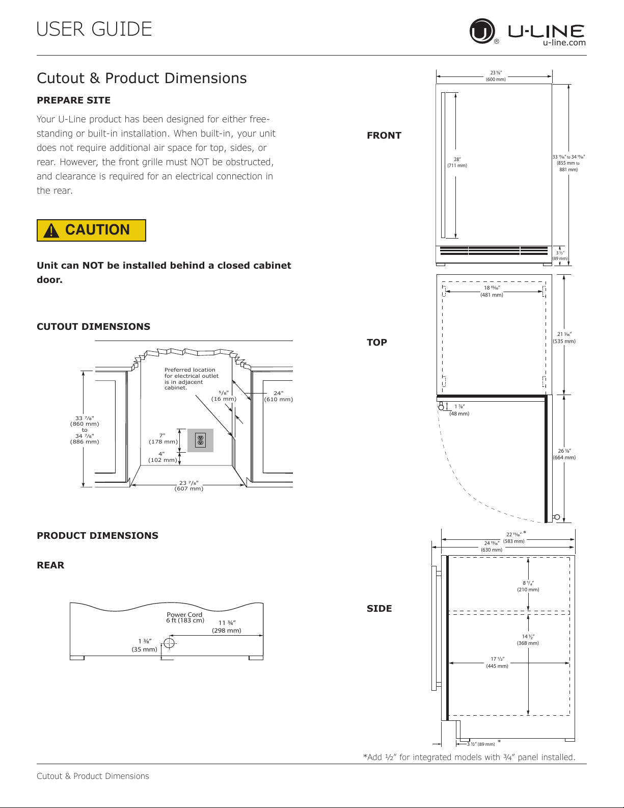
PREPARE SITE
Your U-Line product has been designed for either free-
standing or built-in installation. When built-in, your unit
does not require additional air space for top, sides, or
rear. However, the front grille must NOT be obstructed,
and clearance is required for an electrical connection in
the rear.
CAUTION
!
Unit can NOT be installed behind a closed cabinet
door.
CUTOUT DIMENSIONS
PRODUCT DIMENSIONS
REAR
FRONT
TOP
SIDE
4"
(102 mm)
7"
(178 mm)
24"
(610 mm)
23 7/8"
(607 mm)
33 7⁄8"
(860 mm)
to
34 7⁄8"
(886 mm)
Preferred location
for electrical outlet
is in adjacent
cabinet.
5/8"
(16 mm)
Power Cord
6 ft (183 cm)
1 ⁄”
(35 mm)
11 ¾”
(298 mm)
23 ⁄”
(600 mm)
3 ½”
(89 mm)
33 ⁄”
to
34 ⁄”
(855 mm
to
881 mm)
28”
(711 mm)
1 ⁄”
(48 mm)
18 ⁄”
(481 mm)
26 ⁄”
(664 mm)
21 ⁄”
(535 mm)
*
*
*Add 1⁄2” for integrated models with 3⁄4” panel installed.
8
USER GUIDE
Side-by-Side Installation
u-line.com
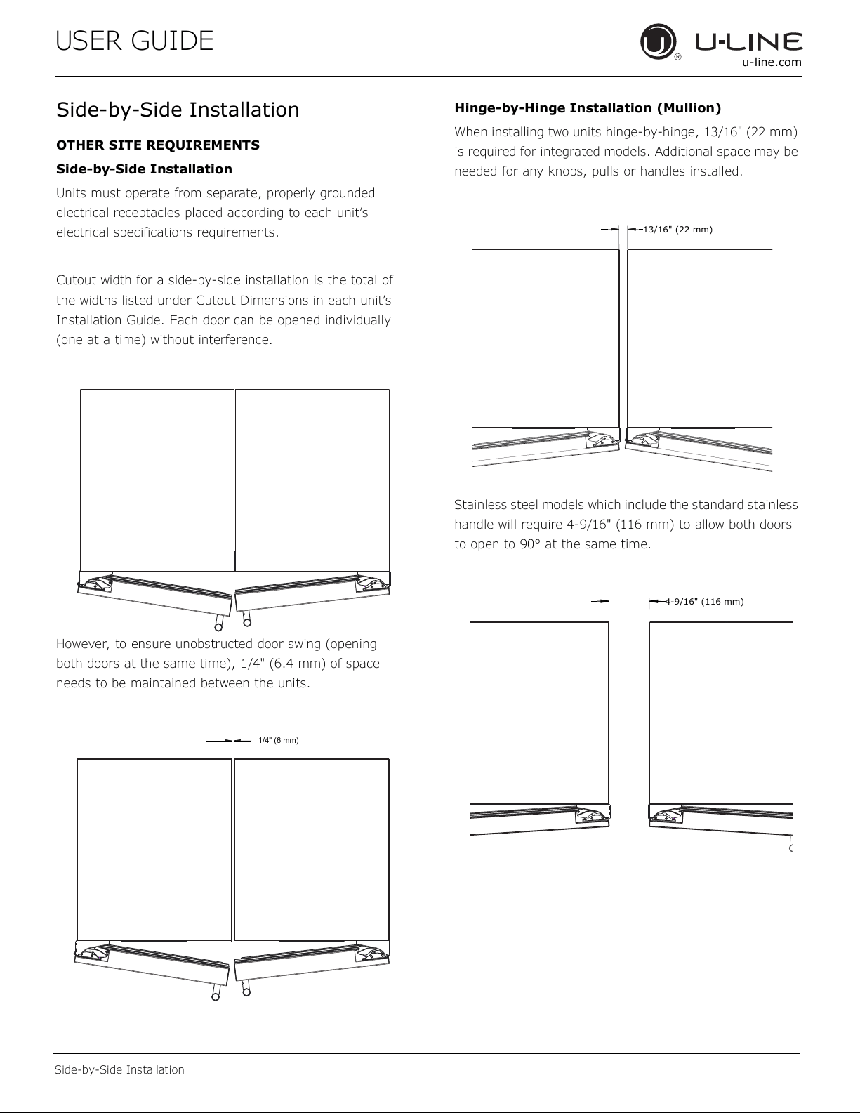
Side-by-Side Installation
OTHER SITE REQUIREMENTS
Side-by-Side Installation
Units must operate from separate, properly grounded
electrical receptacles placed according to each unit’s
electrical specifications requirements.
Cutout width for a side-by-side installation is the total of
the widths listed under Cutout Dimensions in each unit’s
Installation Guide. Each door can be opened individually
(one at a time) without interference.
However, to ensure unobstructed door swing (opening
both doors at the same time), 1/4" (6.4 mm) of space
needs to be maintained between the units.
Hinge-by-Hinge Installation (Mullion)
When installing two units hinge-by-hinge, 13/16" (22 mm)
is required for integrated models. Additional space may be
needed for any knobs, pulls or handles installed.
Stainless steel models which include the standard stainless
handle will require 4-9/16" (116 mm) to allow both doors
to open to 90° at the same time.
1/4" (6 mm)
13/16" (22 mm)
4-9/16" (116 mm)
9
USER GUIDE
u-line.com
Anti-Tip Bracket
Anti-Tip Bracket
Use one of the methods below to secure the unit
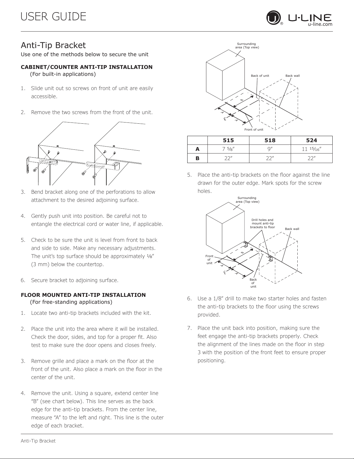
CABINET/COUNTER ANTI-TIP INSTALLATION
(For built-in applications)
1. Slide unit out so screws on front of unit are easily
accessible.
2. Remove the two screws from the front of the unit.
3. Bend bracket along one of the perforations to allow
attachment to the desired adjoining surface.
4. Gently push unit into position. Be careful not to
entangle the electrical cord or water line, if applicable.
5. Check to be sure the unit is level from front to back
and side to side. Make any necessary adjustments.
The unit’s top surface should be approximately ”
(3 mm) below the countertop.
6. Secure bracket to adjoining surface.
FLOOR MOUNTED ANTI-TIP INSTALLATION
(For free-standing applications)
1. Locate two anti-tip brackets included with the kit.
2. Place the unit into the area where it will be installed.
test to make sure the door opens and closes freely.
3.
center of the unit.
4. Remove the unit. Using a square, extend center line
“B” (see chart below). This line serves as the back
edge for the anti-tip brackets. From the center line,
edge of each bracket.
C
L
Back wall
Back of unit
Front of unit
Surrounding
area (Top view)
A
A
B
515 518 524
A 7 9” 11 ”
B 22” 22” 22”
5.
drawn for the outer edge. Mark spots for the screw
holes.
C
L
Surrounding
area (Top view)
Drill holes and
mount anti-tip
brackets to floor
Back wall
Front
of
unit
Back
of
unit
A
A
B
6. Use a 1/8” drill to make two starter holes and fasten
provided.
7. Place the unit back into position, making sure the
feet engage the anti-tip brackets properly. Check
3 with the position of the front feet to ensure proper
positioning.
10
USER GUIDE
u-line.com
General Installation
General Installation
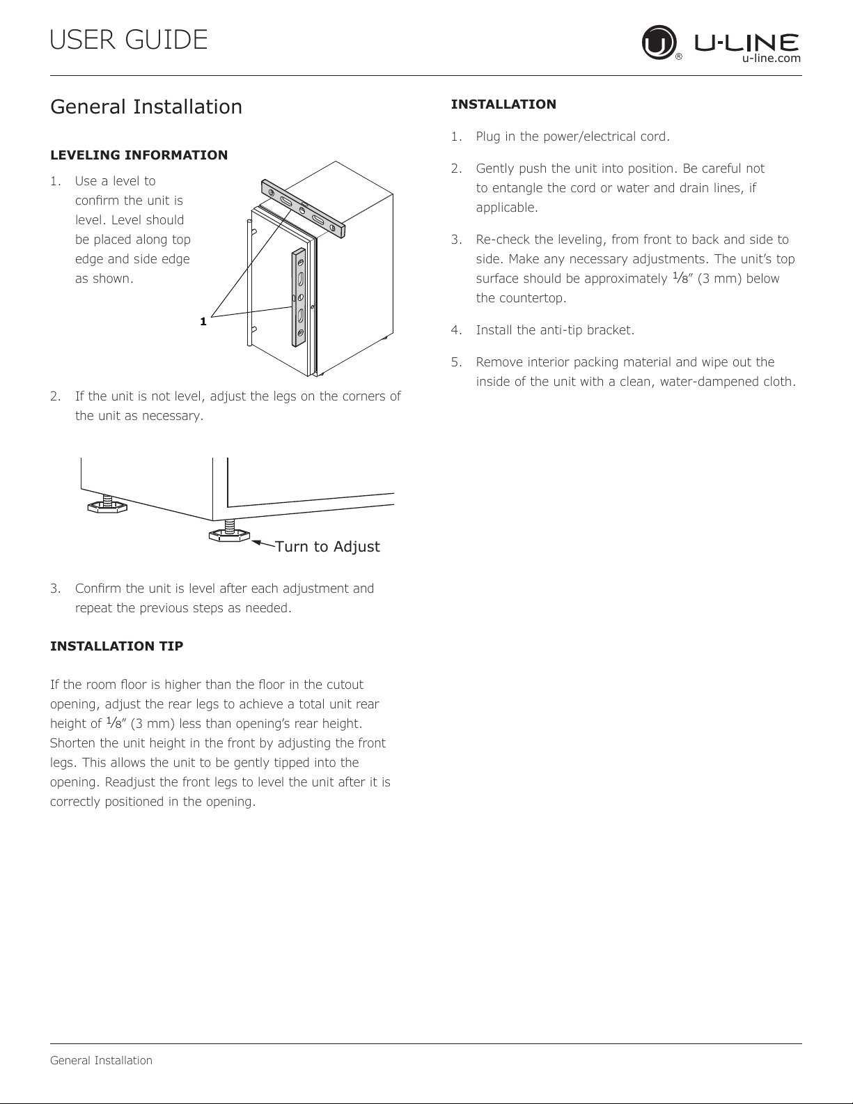
LEVELING INFORMATION
1. Use a level to
conrm the unit is
level. Level should
be placed along top
edge and side edge
as shown.
2. If the unit is not level, adjust the legs on the corners of
the unit as necessary.
3. Conrm the unit is level after each adjustment and
repeat the previous steps as needed.
INSTALLATION TIP
If the room oor is higher than the oor in the cutout
opening, adjust the rear legs to achieve a total unit rear
height of
1⁄8” (3 mm) less than opening’s rear height.
Shorten the unit height in the front by adjusting the front
legs. This allows the unit to be gently tipped into the
opening. Readjust the front legs to level the unit after it is
correctly positioned in the opening.
INSTALLATION
1. Plug in the power/electrical cord.
2. Gently push the unit into position. Be careful not
to entangle the cord or water and drain lines, if
applicable.
3. Re-check the leveling, from front to back and side to
side. Make any necessary adjustments. The unit’s top
surface should be approximately
1⁄8” (3 mm) below
the countertop.
4. Install the anti-tip bracket.
5. Remove interior packing material and wipe out the
inside of the unit with a clean, water-dampened cloth.
1
Turn to Adjust
11
USER GUIDE
Grille Installation
u-line.com
Grille Installation
REMOVING AND INSTALLING GRILLE
WARNING
!
Disconnect electric power to the unit before
removing the grille.
When using the unit, the grille must be installed.
WARNING
!
DO NOT touch the condenser fins. The condenser
fins are SHARP and can be easily damaged.
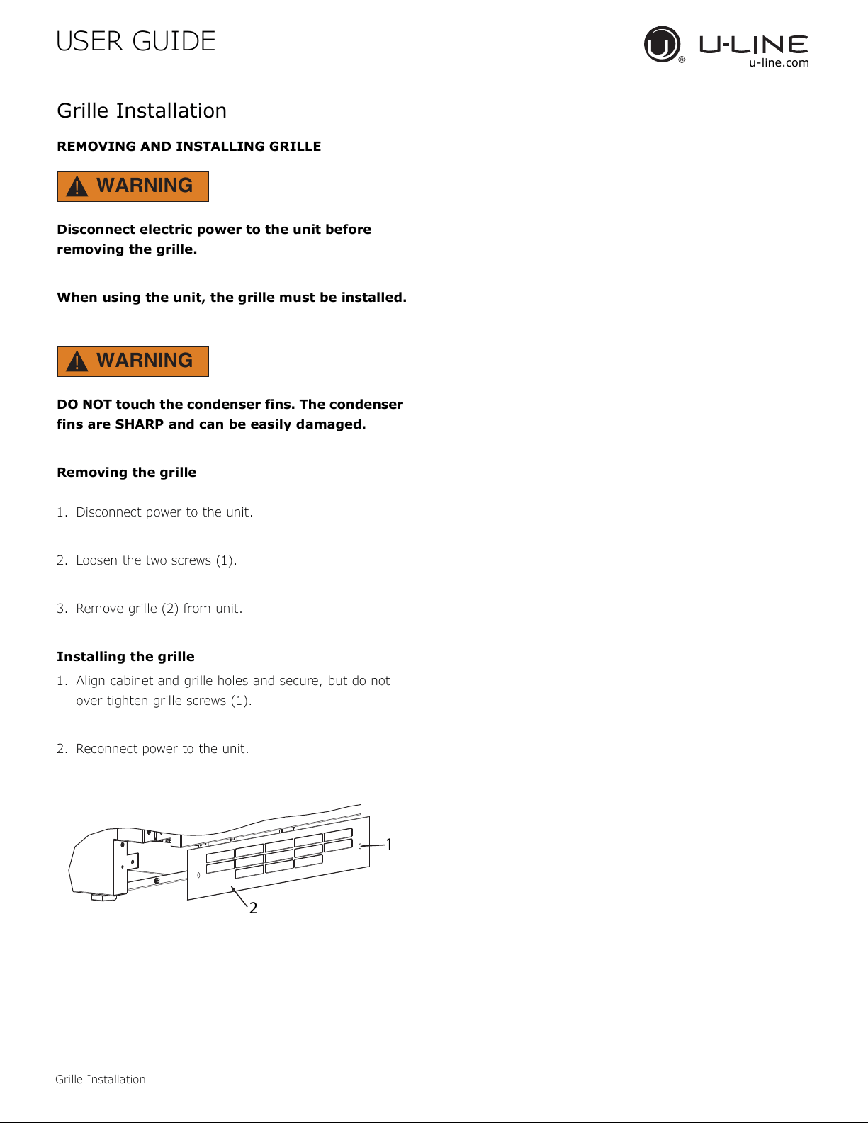
Removing the grille
1. Disconnect power to the unit.
2. Loosen the two screws (1).
3. Remove grille (2) from unit.
Installing the grille
1. Align cabinet and grille holes and secure, but do not
over tighten grille screws (1).
2. Reconnect power to the unit.
1
2
12
USER GUIDE
Door Swing
u-line.com
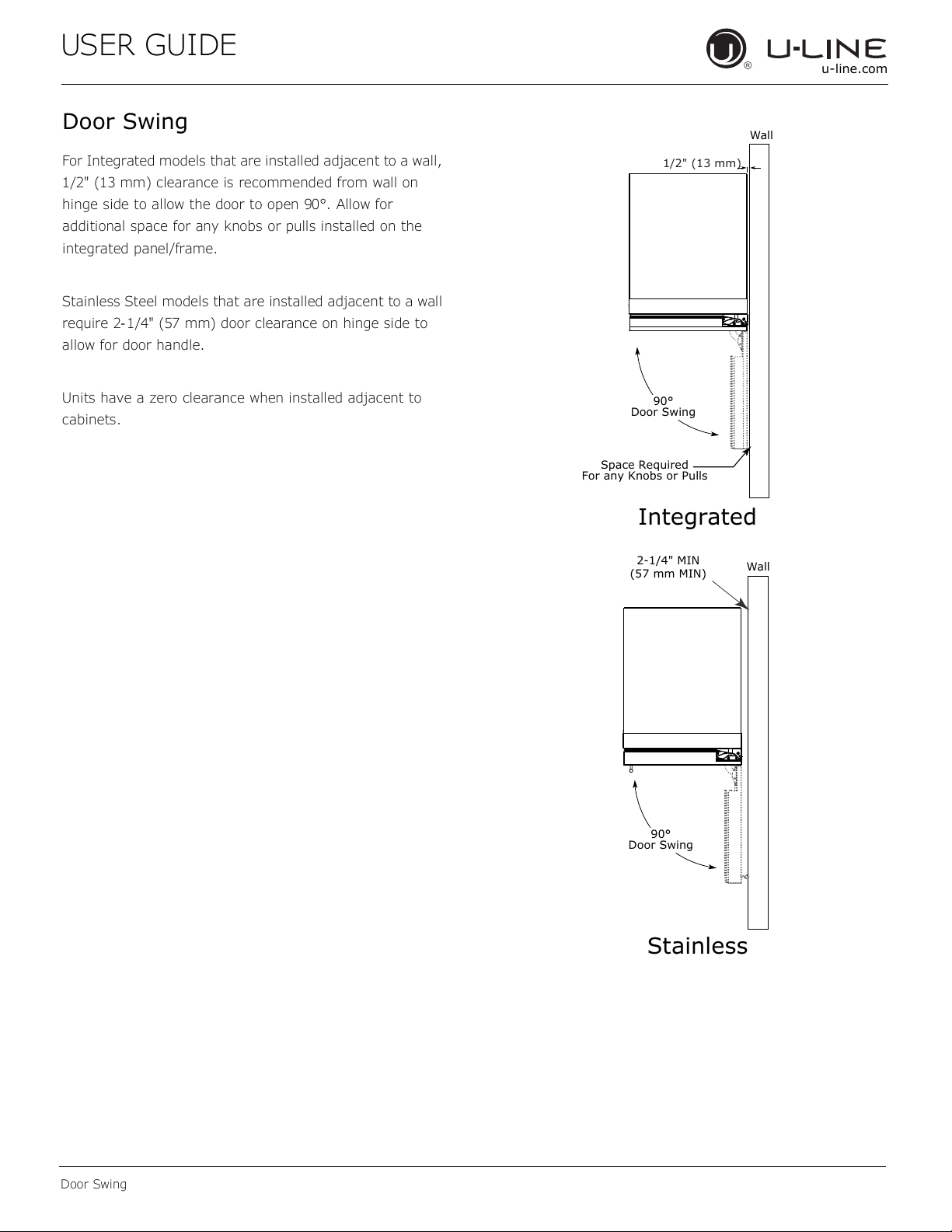
Door Swing
For Integrated models that are installed adjacent to a wall,
1/2" (13 mm) clearance is recommended from wall on
hinge side to allow the door to open 90°. Allow for
additional space for any knobs or pulls installed on the
integrated panel/frame.
Stainless Steel models that are installed adjacent to a wall
require 2- 1/4" (57 mm) door clearance on hinge side to
allow for door handle.
Units have a zero clearance when installed adjacent to
cabinets.
Wall
Wall
90°
Door Swing
90°
Door Swing
Space Required
For any Knobs or Pulls
2-1/4" MIN
(57 mm MIN)
Integrated
Stainless
1/2" (13 mm)
13
USER GUIDE
u-line.com
Door Adjustments
Door Adjustments
DOOR ALIGNMENT AND ADJUSTMENT
Align and adjust the door if it is not level or not sealing
properly. If the door is not sealed, the unit may not cool
properly, or excessive frost or condensation may form in
the interior.
NOTICE
Properly aligned, the door’s gasket should be
rmly in contact with the cabinet all the way
around the door (no gaps). Carefully examine the
door’s gasket to ensure that it is rmly in contact
with the cabinet. Also make sure the door gasket
is not pinched on the hinge side of the door.
Do not attempt to use the door to raise or pivot
your unit. This would put excessive stress on the
hinge system.
Alignment and Adjustment Procedure
1. Open door and remove gasket near the hinges.
2. Using a T-25 Torx bit, loosen each pair of Torx head
screws both the upper and lower hinge plates.
3. Square and align door as necessary.
4. Tighten Torx head screws on hinge.
5. Reinstall gasket into the channel starting at the corner.
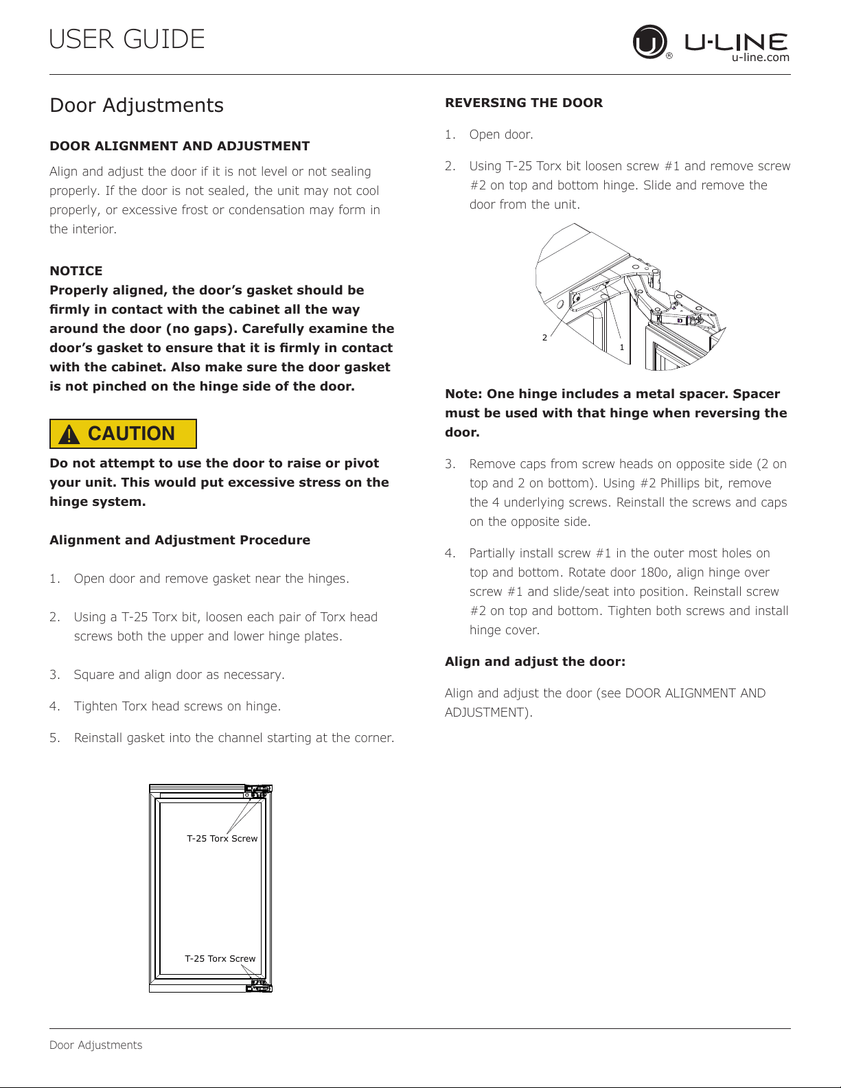
REVERSING THE DOOR
1. Open door.
2. Using T-25 Torx bit loosen screw #1 and remove screw
#2 on top and bottom hinge. Slide and remove the
door from the unit.
Note: One hinge includes a metal spacer. Spacer
must be used with that hinge when reversing the
door.
3. Remove caps from screw heads on opposite side (2 on
top and 2 on bottom). Using #2 Phillips bit, remove
the 4 underlying screws. Reinstall the screws and caps
on the opposite side.
4. Partially install screw #1 in the outer most holes on
top and bottom. Rotate door 180o, align hinge over
screw #1 and slide/seat into position. Reinstall screw
#2 on top and bottom. Tighten both screws and install
hinge cover.
Align and adjust the door:
Align and adjust the door (see DOOR ALIGNMENT AND
ADJUSTMENT).
T-25 Torx Screw
T-25 Torx Screw
2
1
CAUTION
!
14
USER GUIDE
u-line.com
First Use
Temperature displayed reects actual
temperature inside unit.
Initial startup requires no adjustments. When plugged
in, the unit will begin operating under the factory default
settings. If the unit was turned o during installation,
simply press and the unit will immediately switch on. To
turn the unit o, press .
If the temperature displayed is dierent than selected, the
unit is progressing towards the selected temperature. Time
to reach set point varies based upon ambient temperature,
temperature of product loaded, door openings, etc. U-Line
recommends allowing the unit to reach set points before
loading.
NOTICE
First Use
15
USER GUIDE
u-line.com
Control Operation
Control Operation
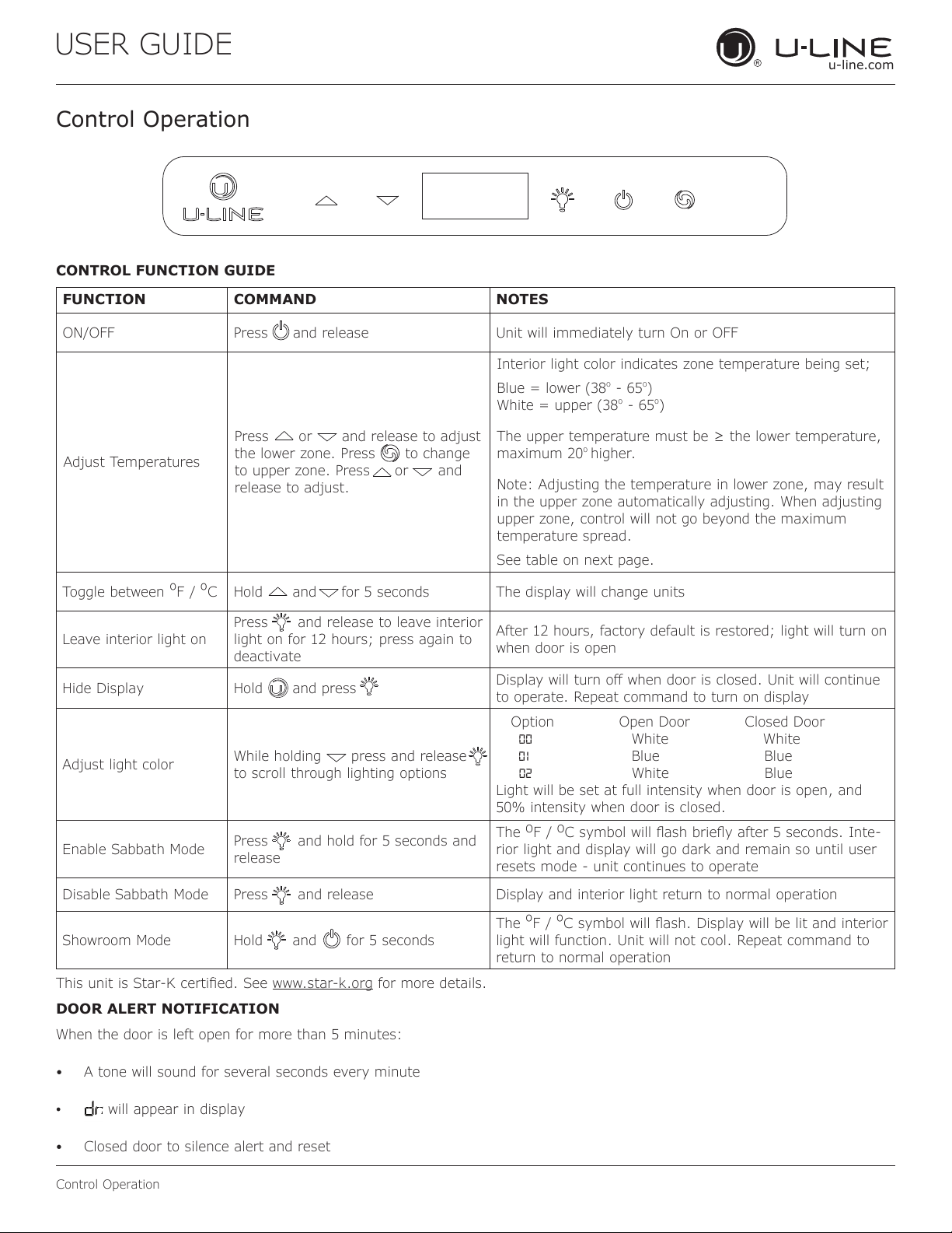
CONTROL FUNCTION GUIDE
FUNCTION COMMAND NOTES
ON/OFF Press and release Unit will immediately turn On or OFF
Adjust Temperatures
Press or and release to adjust
the lower zone. Press to change
to upper zone. Press or and
release to adjust.
Interior light color indicates zone temperature being set;
Blue = lower (38
o
- 65
o
)
White = upper (38
o
- 65
o
)
The upper temperature must be ≥ the lower temperature,
maximum 20
o
higher.
Note: Adjusting the temperature in lower zone, may result
in the upper zone automatically adjusting. When adjusting
upper zone, control will not go beyond the maximum
temperature spread.
See table on next page.
Toggle between
º
F /
º
C Hold and for 5 seconds The display will change units
Leave interior light on
Press and release to leave interior
light on for 12 hours; press again to
deactivate
After 12 hours, factory default is restored; light will turn on
when door is open
Hide Display Hold and press
Display will turn o when door is closed. Unit will continue
to operate. Repeat command to turn on display
Adjust light color
While holding press and release
to scroll through lighting options
Option Open Door Closed Door
00 White White
01 Blue Blue
02 White Blue
Light will be set at full intensity when door is open, and
50% intensity when door is closed.
Enable Sabbath Mode
Press and hold for 5 seconds and
release
The
o
F /
o
C symbol will ash briey after 5 seconds. Inte-
rior light and display will go dark and remain so until user
resets mode - unit continues to operate
Disable Sabbath Mode Press and release Display and interior light return to normal operation
Showroom Mode Hold and for 5 seconds
The
º
F /
º
C symbol will ash. Display will be lit and interior
light will function. Unit will not cool. Repeat command to
return to normal operation
This unit is Star-K certied. See www.star-k.org for more details.
DOOR ALERT NOTIFICATION
When the door is left open for more than 5 minutes:
• A tone will sound for several seconds every minute
•
will appear in display
• Closed door to silence alert and reset
16
USER GUIDE
u-line.com
Control Operation
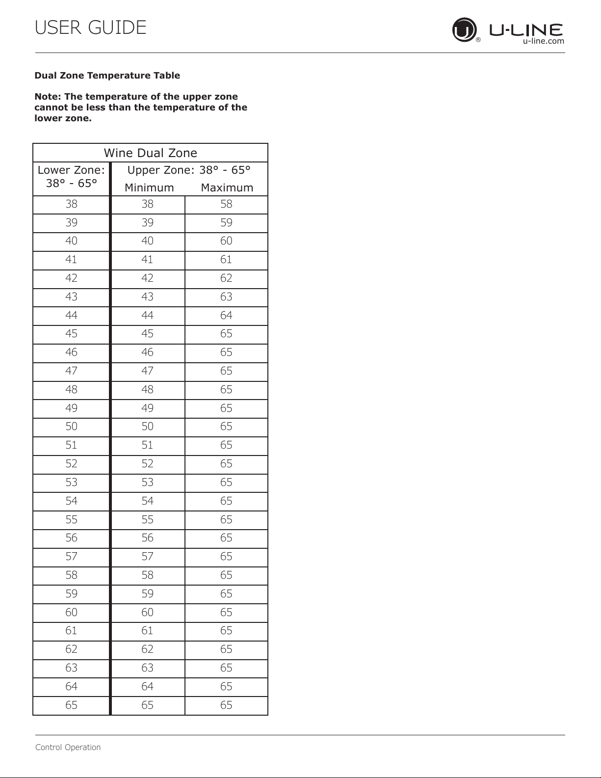
Dual Zone Temperature Table
Note: The temperature of the upper zone
cannot be less than the temperature of the
lower zone.
Wine Dual Zone
Lower Zone:
38° - 65°
Upper Zone: 38° - 65°
Minimum Maximum
38 38 58
39 39 59
40 40 60
41 41 61
42 42 62
43 43 63
44 44 64
45 45 65
46 46 65
47 47 65
48 48 65
49 49 65
50 50 65
51 51 65
52 52 65
53 53 65
54 54 65
55 55 65
56 56 65
57 57 65
58 58 65
59 59 65
60 60 65
61 61 65
62 62 65
63 63 65
64 64 65
65 65 65
17
USER GUIDE
Airflow & Product Loading
u-line.com
Airflow & Product Loading
AIRFLOW
External
• Do not block the front grille - no additional clearance
around sides, top or rear of unit is needed for
ventilation
• Do not install behind a closed door
Internal
• When loading, leave space between internal fans,
vents, and side walls to allow air to circulate freely
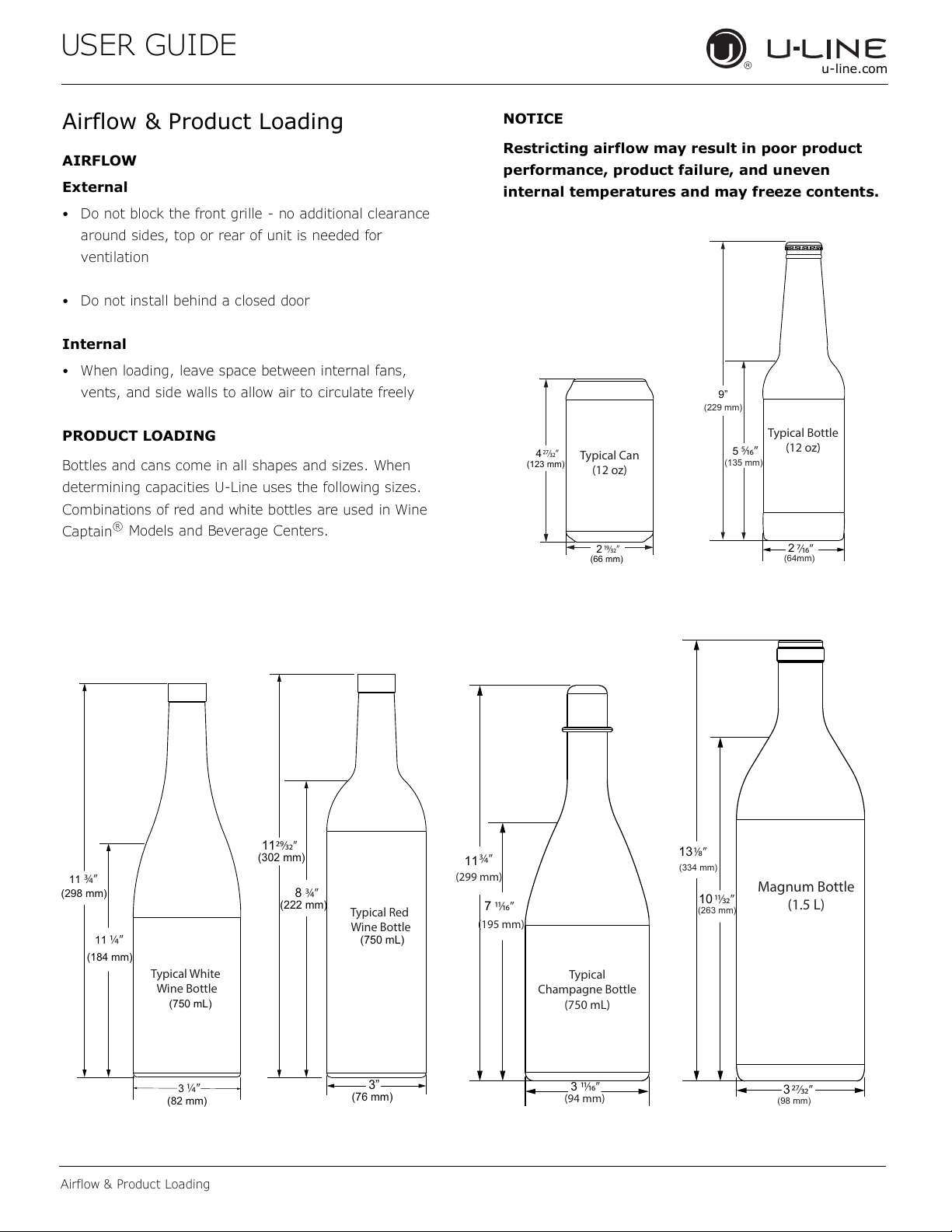
PRODUCT LOADING
Bottles and cans come in all shapes and sizes. When
determining capacities U-Line uses the following sizes.
Combinations of red and white bottles are used in Wine
Captain
®
Models and Beverage Centers.
NOTICE
Restricting airflow may result in poor product
performance, product failure, and uneven
internal temperatures and may freeze contents.
Typical Can
(12 oz)
4
(123 mm)
(66 mm)
2
⁄”
⁄”
Typical Bottle
(12 oz)
9”
5
2
⁄”
⁄”
(135 mm)
(64mm)
(229 mm)
Typical Red
Wine Bottle
11
(302 mm)
8
3”
⁄”
¾”
(222 mm)
(750 mL)
(76 mm)
Magnum Bottle
(1.5 L)
13
10
3
⁄”
(334 mm)
⁄”
(263 mm)
⁄”
(98 mm)
Typical
Champagne Bottle
(750 mL)
3 ⁄”
7
¾”
⁄”
(299 mm)
(94 mm)
(195 mm)
11
Typical White
Wine Bottle
11
(298 mm)
(750 mL)
3
¾”
(184 mm)
(82 mm)
11
¼”
¼”
18
USER GUIDE
u-line.com
Interior Adjustments
Interior Adjustments
Dual Zone Wine Captain
®
models feature side mounted
rack supports with 17 adjustment positions.
Dual Zone models ship with 6 racks. Remove and
reposition racks as desired to accommodate a variety of
bottle sizes and shapes.
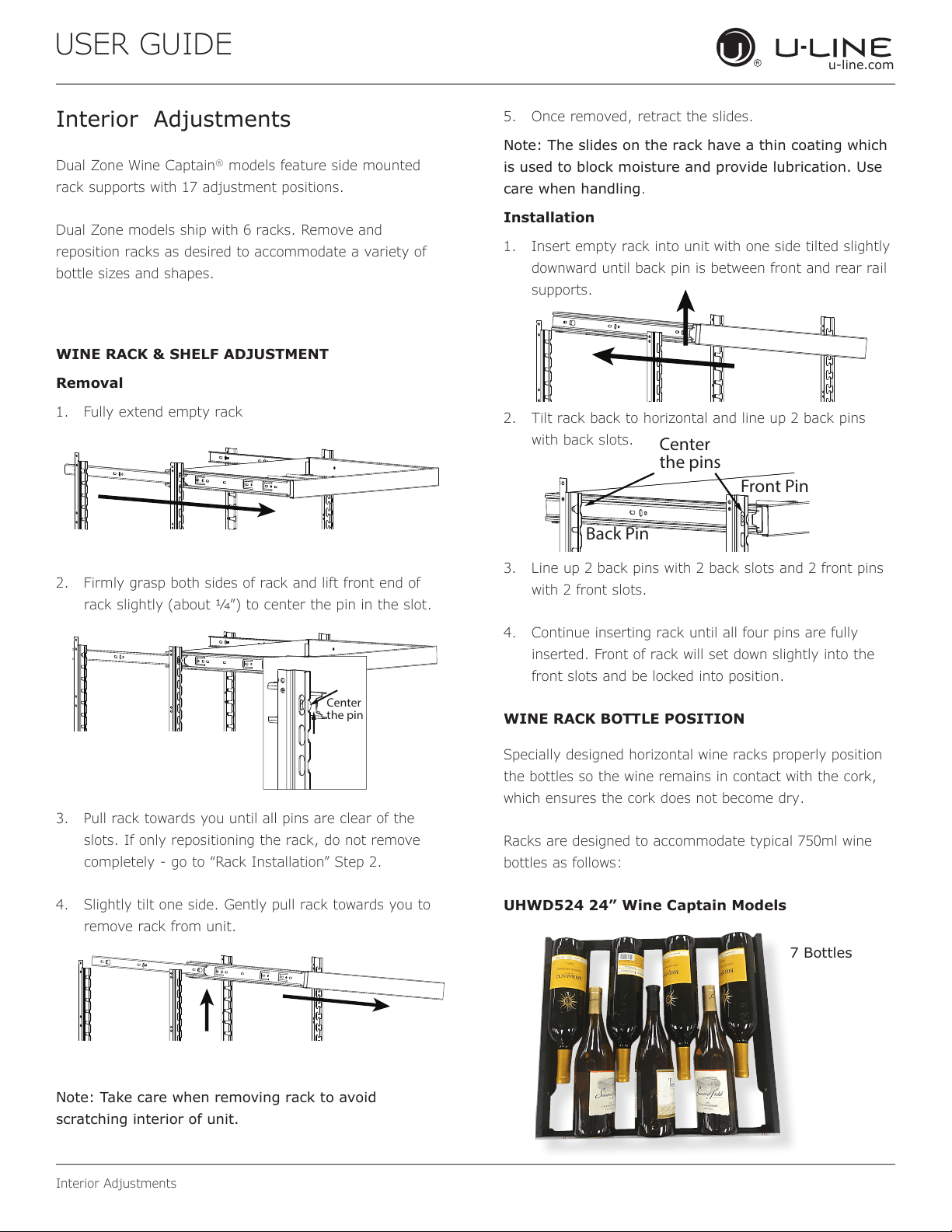
WINE RACK & SHELF ADJUSTMENT
Removal
1. Fully extend empty rack
2. Firmly grasp both sides of rack and lift front end of
rack slightly (about 1/4”) to center the pin in the slot.
3. Pull rack towards you until all pins are clear of the
slots. If only repositioning the rack, do not remove
completely - go to “Rack Installation” Step 2.
4. Slightly tilt one side. Gently pull rack towards you to
remove rack from unit.
Note: Take care when removing rack to avoid
scratching interior of unit.
5. Once removed, retract the slides.
Note: The slides on the rack have a thin coating which
is used to block moisture and provide lubrication. Use
care when handling.
Installation
1. Insert empty rack into unit with one side tilted slightly
downward until back pin is between front and rear rail
supports.
2. Tilt rack back to horizontal and line up 2 back pins
with back slots.
3. Line up 2 back pins with 2 back slots and 2 front pins
with 2 front slots.
4. Continue inserting rack until all four pins are fully
inserted. Front of rack will set down slightly into the
front slots and be locked into position.
WINE RACK BOTTLE POSITION
Specially designed horizontal wine racks properly position
the bottles so the wine remains in contact with the cork,
which ensures the cork does not become dry.
Racks are designed to accommodate typical 750ml wine
bottles as follows:
UHWD524 24” Wine Captain Models
Center
the pins
Front Pin
Back Pin
Center
the pin
7 Bottles
19
USER GUIDE
Cleaning
u-line.com
Cleaning
Stainless Models
Stainless door panels and handles can discolor when
exposed to chlorine gas, pool chemicals, saltwater or
cleaners with bleach.
Keep your stainless unit looking new by cleaning with a
good quality all-in-one stainless steel cleaner and polish
monthly. For best results use Claire
®
Stainless Steel
Polish and Cleaner. Comparable products are acceptable.
Frequent cleaning will remove surface contamination that
could lead to rust. Some installations may require cleaning
weekly.
Do not clean with steel wool pads.
Do not use stainless steel cleaners or polishes on
any glass surfaces.
Clean any glass surfaces with a non-chlorine glass
cleaner.
Do not use cleaners not specifically intended for
stainless steel on stainless steel surfaces (this
includes glass, tile and counter cleaners).
If any surface discoloring or rusting appears, clean it
quickly with Bon-Ami
®
or Barkeepers Friend Cleanser
®
and a nonabrasive cloth. Always clean with the grain.
Always finish with Claire
®
Stainless Steel Polish and
Cleaner or comparable product to prevent further
problems.
Using abrasive pads such as Scotchbrite™ will
cause the graining in the stainless steel to
become blurred.
Rust not cleaned up promptly can penetrate the
surface of the stainless steel and complete
removal of the rust may not be possible.
Integrated Models
To clean integrated panels, use household cleaner per the
cabinet manufacturer’s recommendation.
INTERIOR CLEANING
Disconnect power to the unit.
Clean the interior and all removed components using a
mild nonabrasive detergent and warm water solution
applied with a soft sponge or non-abrasive cloth.
Rinse the interior using a soft sponge and clean water.
Do not use any solvent-based or abrasive
cleaners. These types of cleaners may transfer taste to
the interior products and damage or discolor the lining.
DEFROSTING
Under normal conditions this unit does not require manual
defrosting. Minor frost on the rear wall or visible through
the evaporator plate vents is normal and will melt during
each off cycle.
If there is excessive build-up of 1/4" (6 mm) or more,
manually defrost the unit.
Ensure the door is closing and sealing properly.
High ambient temperature and excessive humidity can
also produce frost.
CAUTION
!
DO NOT use an ice pick or other sharp
instrument to help speed up defrosting. These
instruments can puncture the inner lining or
damage the cooling unit. DO NOT use any type of
heater to defrost. Using a heater to speed up
defrosting can cause personal injury and
damage to the inner lining.
20
USER GUIDE
Cleaning
u-line.com
NOTICE
The drain pan was not designed to capture the
water created when manually defrosting. To
prevent water from overflowing the drain pan
and possibly damaging water sensitive flooring,
the unit must be removed from cabinetry.
To defrost:
1. Disconnect power to the unit.
2. Remove all products from the interior.
3. Prop the door in an open position (2 in. [50 mm]
minimum).
4. Allow the frost to melt naturally.
5. After the frost melts completely clean the interior and
all removed components. (See INTERIOR CLEANING).
6. When the interior is dry, reconnect power and turn unit
on.
21
USER GUIDE
u-line.com
Cleaning Condenser
Cleaning Condenser
INTERVAL - EVERY SIX MONTHS
To maintain operational eciency, keep the front grille free
of dust and lint, and clean the condenser when necessary.
Depending on environmental conditions, more or less
frequent cleaning may be necessary.
WARNING
!
Disconnect electric power to the unit before
cleaning the condenser.
NOTICE
DO NOT use any type of cleaner on the condenser
unit. Condenser may be cleaned using a vacuum,
soft brush, or compressed air.
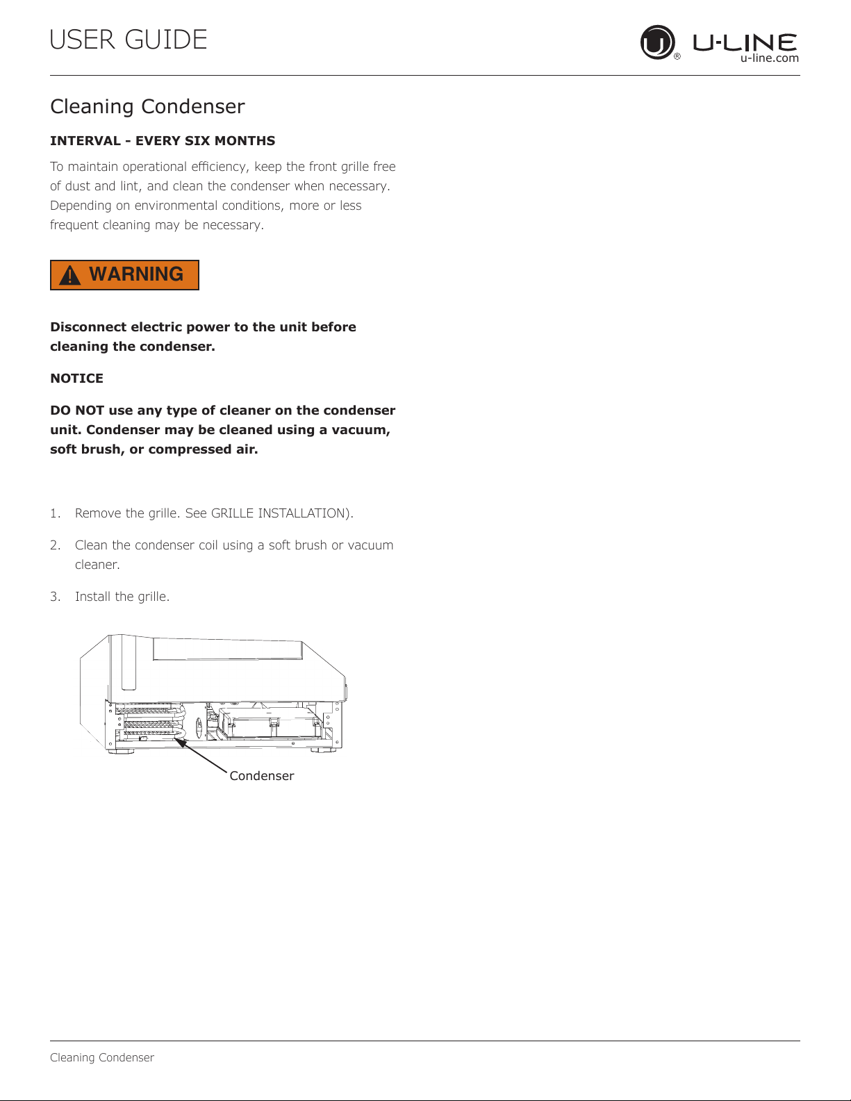
1. Remove the grille. See GRILLE INSTALLATION).
2. Clean the condenser coil using a soft brush or vacuum
cleaner.
3. Install the grille.
Condenser
22
USER GUIDE
Extended Non-Use
u-line.com
Extended Non-Use
VACATION/HOLIDAY, PROLONGED SHUTDOWN
The following steps are recommended for periods of
extended non-use:
1. Remove all consumable content from the unit.
2. Disconnect the power cord from its outlet/socket and
leave it disconnected until the unit is returned to
service.
3. If ice is on the evaporator, allow ice to thaw naturally.
4. Clean and dry the interior of the unit. Ensure all water
has been removed from the unit.
5. The door must remain open to prevent formation of
mold and mildew. Open door a minimum of 2"
(50 mm) to provide the necessary ventilation.
WINTERIZATION
If the unit will be exposed to temperatures of 40°F (5°C)
or less, the steps above must be followed.
For questions regarding winterization, please
call U-Line at 800.779.2547.
CAUTION
!
Damage caused by freezing temperatures is not
covered by the warranty.
23
USER GUIDE
u-line.com
Troubleshooting
u-line.com
If you think your U-Line product is malfunctioning, read the
CONTROL OPERATION section to clearly understand the
function of the control.
If the problem persists, read the NORMAL OPERATING
SOUNDS and TROUBLESHOOTING GUIDE sections below
to help you quickly identify common problems and possible
causes and remedies. Most often, this will resolve the
problem without the need to call for service.
If you do not understand a troubleshooting remedy, or your
product needs service, contact U-Line Corporation directly
at +1.800.779.2547.
When you call, you will need your product Model and Serial
Numbers. This information appears on the Model and Serial
number plate located on the upper right or rear wall of the
interior of your product.
All models incorporate rigid foam insulated cabinets to
provide high thermal eciency and maximum sound
reduction for its internal working components. Despite this
technology, your model may make sounds that are
unfamiliar.
Normal operating sounds may be more noticeable because
of the unit’s environment. Hard surfaces such as cabinets,
wood, vinyl or tiled oors and paneled walls have a
tendency to reect normal appliance operating noises.
Listed below are common refrigeration components with a
brief description of the normal operating sounds they
make. NOTE: Your product may not contain all the
components listed.
• Compressor: The compressor makes a hum or pulsing
sound that may be heard when it operates.
BEFORE CALLING FOR SERVICE
TROUBLESHOOTING GUIDE
ELECTROCUTION HAZARD. Never attempt to
repair or perform maintenance on the unit
before disconnecting the main electrical power.
Troubleshooting - What to check when problems occur:
NORMAL OPERATING SOUNDS
IF SERVICE IS REQUIRED
Troubleshooting
• Evaporator: Refrigerant owing through an evaporator
may sound like boiling liquid.
• Condenser Fan: Air moving through a condenser may
be heard.
• Automatic Defrost Drain Pan: Water may be heard
dripping or running into the drain pan when the unit is
in the defrost cycle.
DANGER
!
Problem Possible Cause and Remedy
Interior Light
Does Not
Illuminate
If the unit is cooling, it may be in
Sabbath mode.
Light Remains
on When Door
Is Closed.
Turn o light switch if equipped.
Adjust light actuator bracket on bottom
of door.
Unit Develops
Frost on
Internal
Surfaces.
Ensure the door is closing and sealing
properly.
Unit Develops
Condensation
on External
Surfaces.
The unit is exposed to excessive
humidity. Moisture will dissipate as
humidity levels decrease.
Product is Not
Cold Enough
Air temperature does not indicate
product temperature. See CHECKING
PRODUCT TEMPERATURE below.
Adjust the temperature to a cooler set
point.
Ensure unit is not located in excessive
ambient temperatures or in direct
sunlight.
Ensure the door is closing and sealing
properly.
Ensure the interior light has not
remained on too long.
Ensure nothing is blocking the front
grille, found at the bottom of the unit.
Ensure the condenser coil is clean and
free of any dirt or lint build-up.
24
USER GUIDE
u-line.comu-line.com
Troubleshooting
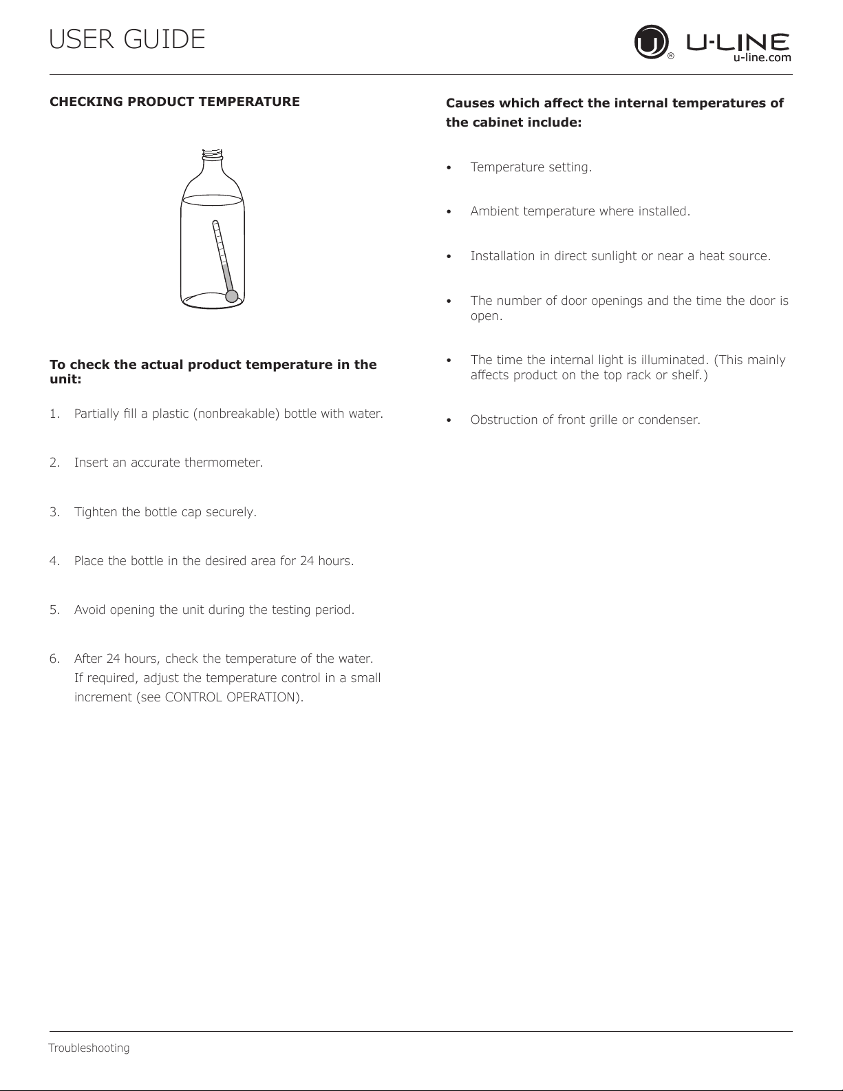
CHECKING PRODUCT TEMPERATURE
To check the actual product temperature in the
unit:
1. Partially ll a plastic (nonbreakable) bottle with water.
2. Insert an accurate thermometer.
3. Tighten the bottle cap securely.
4. Place the bottle in the desired area for 24 hours.
5. Avoid opening the unit during the testing period.
6. After 24 hours, check the temperature of the water.
If required, adjust the temperature control in a small
increment (see CONTROL OPERATION).
Causes which aect the internal temperatures of
the cabinet include:
• Temperature setting.
• Ambient temperature where installed.
• Installation in direct sunlight or near a heat source.
• The number of door openings and the time the door is
open.
• The time the internal light is illuminated. (This mainly
aects product on the top rack or shelf.)
• Obstruction of front grille or condenser.
25
USER GUIDE
u-line.com
Product Liability
Product Liability
Field service technicians are authorized to make an initial
assessment in the event of reported damages. If there are
any questions about the process involved, the technician
should call U-Line for further explanation.
While inspecting for defects or installation issues, photos
should be taken to document any damages or issues found.
During the assessment, if the service technician is able to
nd the source of the damage and it can be resolved by
replacement of a part, the servicer is authorized to replace
the part in question. The part that caused the damage
must be returned to U-Line in its entirety. The part must
be clearly labeled with the serial number of the unit it was
removed from, the date, and the servicer who removed the
part.
If the service technician determines the damage is the
result of installation issues (water connection/drain, etc.),
the consumer would be notied and the issues shall be
resolved at the direction of the consumer.
If damage is evident and the service technician is
unable to nd the source, U-Line must be contacted at
1.800.799.2547 for further direction.
8900 N. 55th Street • Milwaukee, WI 53223
T: +1.414.354.0300 • F: +1.414.354.5696
Website: www.u-line.com
Right product. Right place.
Right temperature Since 1962.
26
USER GUIDE
u-line.com
Warranty Claims
The following information denes the parameters for ling a
warranty claim:
• Valid serial number needed
• Valid model number needed
• Claims must be submitted online at
www.U-LineService.com
• 60 day submittal deadline from date of completed
service
• Only one repair or unit per warranty claim
• Part order numbers will be required when submitting
for warranty labor
Units must be registered prior to warranty submittal.
Customers may register at www.U-Line.com. A proof
of purchase is required. We also accept the following
information to update warranty:
• New construction occupancy documents
• Closing paperwork
• Final billing - Remodel
Warranty parts will be shipped at no charge after U-Line
conrms warranty status. Please provide the model, serial
number, part number and part description. Some parts will
require color or voltage information.
Warranty Claims
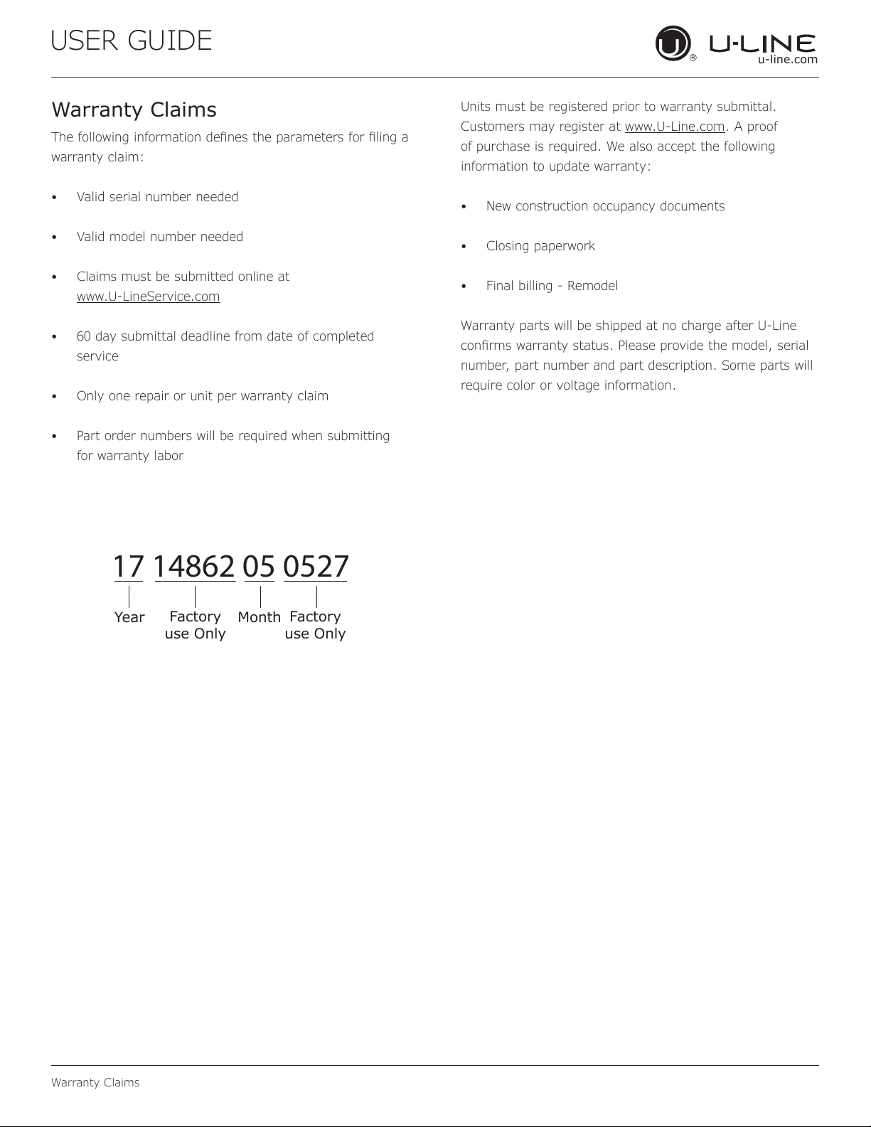
17 14862 05 0527
Year
Factory
use Only
Factory
use Only
Month
27
Copyright © 2020 U-Line Corporation. All Rights Reserved. | Publication Number 30379 | 01/2020 Rev. N
U-Line Corporation (U-Line) Limited Warranty
One Year Limited Warranty
For one year from the date of original purchase, this warranty covers all parts and labor to repair or replace any part of the product that
proves to be defective in materials or workmanship. For products installed and used for normal residential use, material cosmetic defects
are included in this warranty, with coverage limited to 60 days from the date of original purchase. All service provided by U-Line under the
above warranty must be performed by a U-Line factory authorized servicer, unless otherwise specified by U-Line. Service provided during
normal business hours.
Two Year Limited Warranty (5 Class Product)
For two years from the date of original purchase, this warranty covers all parts and labor to repair or replace any part of the product that
proves to be defective in materials or workmanship. For products installed and used for normal residential use, material cosmetic defects
are included in this warranty, with coverage limited to 60 days from the date of original purchase. All service provided by U-Line under the
above warranty must be performed by a U-Line factory authorized servicer, unless otherwise specified by U-Line. Service provided during
normal business hours.
Available Second & Third Year Limited Warranty
In addition to the standard one and two year warranties outlined above, U-Line offers a one year extension of the warranties from the date
of purchase, free of charge. To take advantage of this extension, you must register your product with U-Line within 60 days from the date
of purchase at u-line.com and provide proof of purchase.
Five Year Sealed System Limited Warranty
For five years from the date of original purchase, U-Line will repair or replace the following parts, labor not included, that prove to be
defective in materials or workmanship: compressor, condenser, evaporator, drier, and all connecting tubing. All service provided by U-Line
under the above warranty must be performed by a U-Line factory authorized servicer, unless otherwise specified by U-Line. Service
provided during normal business hours.
Terms
These warranties apply only to products installed in any one of the fifty states of the United States, the District of Columbia, or the ten
provinces of Canada. The warranties do not cover any parts or labor to correct any defect caused by negligence, accident or improper use,
maintenance, installation, service, repair, acts of God, fire, flood or other natural disasters. The product must be installed, operated, and
maintained in accordance with your product’s User Guide.
The remedies described above for each warranty are the only ones that U-Line will provide, either under these warranties or under any
warranty arising by operation of law. U-Line will not be responsible for any consequential or incidental damages arising from the breach of
these warranties or any other warranty, whether express, implied, or statutory. Some states do not allow the exclusion or limitation of
incidental or consequential damages, so the above limitation or exclusion may not apply to you. These warranties give you specific legal
rights, and you may also have other rights which vary from state to state.
Any warranty that may be implied in connection with your purchase or use of the product, including any warranty of merchantability or any
warranty fit for a particular purpose is limited to the duration of these warranties, and only extends to five years in duration for the parts
described in the section related to the five year limited warranty above. Some states do not allow limitations on how long an implied warranty
lasts, so the above limitations may not apply to you.
• The warranties only apply to the original purchaser and are non-transferable.
• The second, third, and five year warranties cover products installed and used for normal residential or designated marine use only.
• The warranties apply to units operated outside only if designed for outdoor use by model and serial number.
• U-Line Commercial products are covered by the one year and 5 year limited warranties and are not eligible for the second and
third year limited warranties.
• Replacement water filters, light bulbs, and other consumable parts are not covered by these warranties.
• The start of U-Line’s obligation is limited to four years after the shipment date from U-Line.
• In-home instruction on how to use your product is not covered by these warranties.
• Food, beverage, and medicine loss are not covered by these warranties.
• If the product is located in an area where U-Line factory authorized service is not available, you may be responsible for a trip
charge or you may be required to bring the product to a U-Line factory authorized service location at your own cost and expense.
• Units purchased after use as floor displays, and/or certified reconditioned units, are covered by the limited one year warranty only
and no coverage is provided for cosmetic defects.
• Signal issues related to Wi-Fi connectivity are not covered by these warranties.
For parts and service assistance, or to find U-Line factory authorized service near you, contact U-Line:
8900 N. 55
th
Street, Milwaukee, WI 53223 • u-line.com • onlineservice@u-line.com • +1.800.779.2547
28