SEARS
Water Softeners
MODEL NOS.
625.3483400
Standard Capacity SST
625.3483500 @
Standard Capacity-SST
WARRANTY
-- START UP/SETTING TIMER --
-- HOW IT WORKS --
-- CARE OF --
-- SPECIFICATIONS --
-- REPAIR PARTS --
SAVE THIS MANUAL
(Use plasticbag and tie provided,to hang manuals nearbythe softener forfuture reference)°
PRINTED IN U S A
WARRANTY
L I
SEARS RESIDENTIAL WATER SOFTENER
FULL ONE YEAR WARRANTY ON WATER SOFTENER
For one year from the date of purchase, when this water softener is installed and maintained
in accordance with our instructions, Sears will repair, free of charge, defects in material
or workmanship in this water softener,
FULL TEN YEAR WARRANTY AGAINST LEAKS
For ten years from the date of purchase, Sears will furnish and install a new current model
water softener tank or salt storage drum, free of charge, if either the tank or drum develop
a leak
TO OBTAIN WARRANTY SERVICE, SIMPLY CONTACT THE NEAREST SEARS SERVICE
CENTER THROUGHOUT THE UNITED STATES. This warranty applies only while this pro-
duct is in use in the United States.
This warranty gives you specific legal rights, and you may have other rights which vary from
state to state.
Sears, Roebuck and Co.., D/817 WA, Hoffman Estates, IL 60179
If you want your water softener professionally installed, talk to your Sears Salesman. He will arrange for
a prompt, quality installation by Sears Authorized Installers.
SEARS INSTALLATION POLICY
All installation labor arranged by Sears shall be per-
formed in a neat, workmanlike manner in accordance
with generally accepted trade practices_ Further, all
installations shall comply with all local laws, codes,
regulations and ordinances. Customer shall also be
protected, during installation, by insurance relating
to Property Damage, Workman's Compensation and
Public Liability.
SEARS iNSTALLATION WARRANTY
In addition to any warranty extended to you on the
Sears merchandise involved, which warranty
becomes effective the date the merchandise is in-
stalled, should the workmanship of any Sears
arranged installation prove faulty within one year,
Sears will, upon notice from you, cause such faults
to be corrected at no additional cost to you.
FACTS AND FIGURES TO KEEP
Fill in the blanks below and keep this book in
a safe place so you always have these facts,
Water Softener Model No 1
Serial Number_____
Date Installed
Water Hardness Grains Per Gallon
Iron Content Parts Per Million
*pH. _Taste And/Or Odor
Water Pressure _Pounds/Square Inch
Water Flow Rate Gallons Per Minute
tThe model number is on the rating decal,
located on the rim, under the salt hole cover.
2
TABLE OF CONTENTS
I J
SECTION 1 SOFTENER START UP
A. SAFETY GUIDES
B.. CHECK LIST OF STEP-BY-STEP GUIDES TO INSTALL
C. PROGRAM THE TIMER
D. SANITIZING THE WATER SOFTENER
E.. FILL THE STORAGE TANK WITH SALT
PAGE
NO.
4
5
6
7
8
SECTION 2 HOW YOUR WATER SOFTENER WORKS
A., FACE PLATE TIMER FEATURES 9-10
B. SOFT WATER SERVICE, AND REGENERATION 11-13
SECTION 3 CARE OF YOUR SOFTENER
A. SALT .... REFILLING STORAGE TANK, SALT BRIDGE 14
B. KEEPING THE WATER SOFTENER CLEAN 15
C. KEEP THE SOFTENER FROM FREEZING 16
D. HELPFUL HINTS CHECKLIST 17
SECTUON4 OTHER THINGS TO KNOW
A. HOW TO "FINE-TUNE" YOUR WATER SOFTENER 18-20
B DIMENSIONS/SPECIFICATIONS 21
SECTION 5
A. ELECTRICAL CONNECTIONS
B. REGENERATION CYCLE TIMES
C. TROUBLESHOOTING
D. ROTARY VALVE SERVICE
E. WATER FLOW THROUGH THE SOFTENER VALVE
SERVICER'S TECH INFORMATION
22
23
24-26
27
28-30
SECTnON 6 REPAIR PARTS 32-35
3

SECTION 1
I ,I
1A. SAFETY GUHDES
A Read all steps, guides and rules carefully be-
fore installing and using your new water softener°
Follow all steps exactly to correctly install. Fail-
ure to follow them could cause personal injury or
property damage. Reading this book will also
help you to get all of the benefits from your water
softener.
A Your water softener will remove hardness
minerals and "clear water" iron from water, up to
the limits shown on page 21. It will not remove
other types of iron, acids, tastes and odors, etc. It
will not purify polluted water or make it safe to
drink.
A Protect the softener and piping from freezing.
Damage from freezing voids the softener war-
ranty. See page 16.
CAUTIONS
PLEASE READ AND COMPLY WITH THE
FOLLOWING GUIDES TO PREVENT
DAMAGE TO THE SOFTENER OR OTHER
PROPERTY, PERSONAL INJURY, OR POSSI-
BLE FATAL SHOCK.
h, THIS SOFTENER WORKS ON 24 VOLTS
ONLY° BE SURE TO USE THE TRANS-
FORMER INCLUDED, AND PLUG IT INTO A
120V OUTLET.
A Unplug the transformer right away if the
power cable should become damaged or
frayed. Make repairs before plugging back in-
to the power outlet°
A Always unplug the softener from electrical
power before removing outer valve covers.
4
SECTION 1 WATER SOFTENER START-UP
t 3
,i
lB. CHECK LIST OF ALL STEP BY STEP GUIDES TO INSTALL
Refer to the Installation Manual, part no. 7141417,
for step-by-step guides.
To be sure you have done all the steps to install the
softener, read the following list.1 Page numbers
referred to are in the Installation Manual.
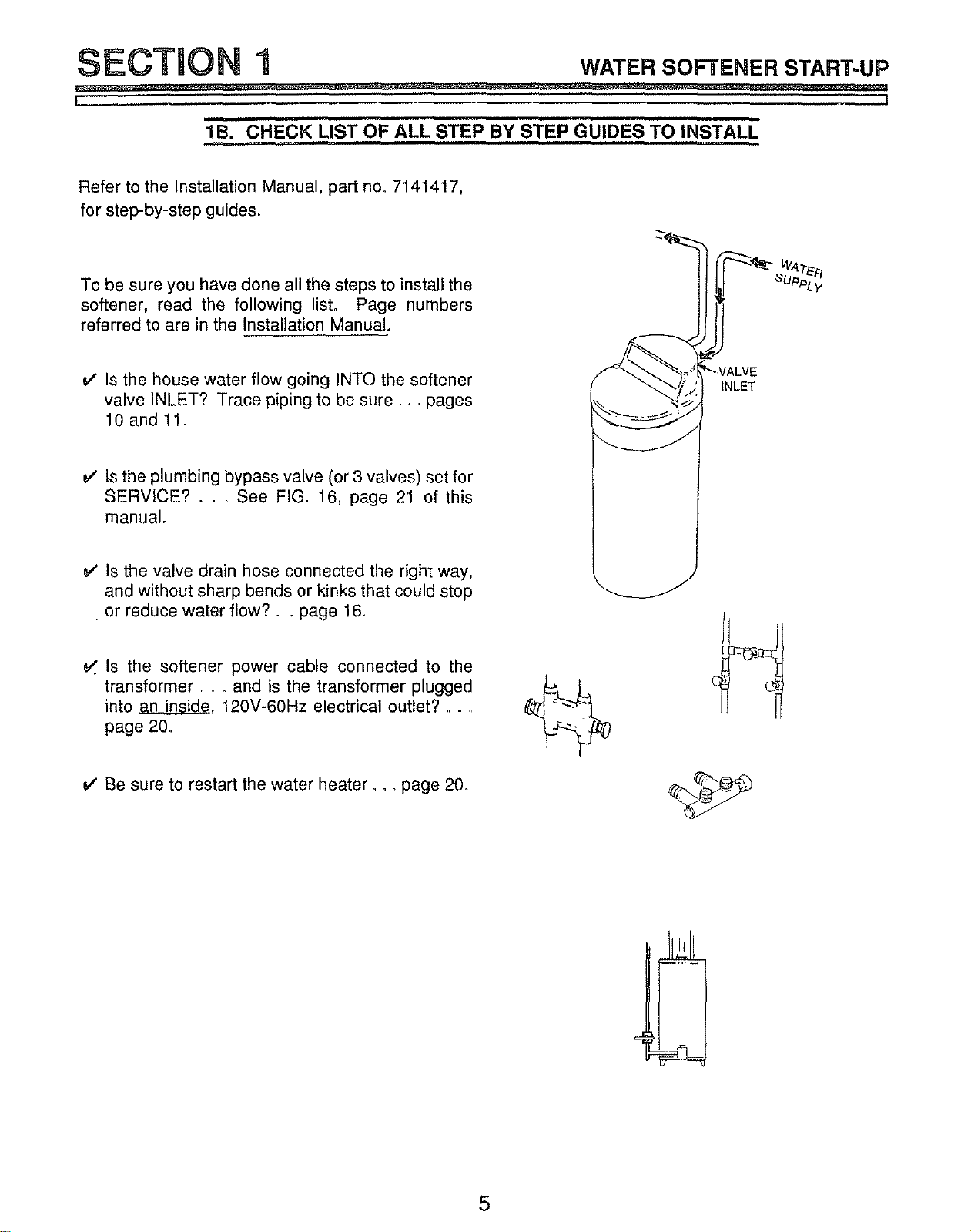
v' Is the house water flow going INTO the softener
valve INLET? Trace piping to be sure .... pages
10 and 11.
tNLET
WAT_,q
SUPPL_,
v' Is the plumbing bypass valve (or 3 valves) set for
SERVICE? . . . See FIG. 16, page 21 of this
manual.
Is the valve drain hose connected the right way,
and without sharp bends or kinks that could stop
or reduce water flow?., page 16.
Is the softener power cable connected to the
transformer .... and is the transformer plugged
into ._, 120V-60Hz electrical outlet?, o.
page 20
v' Be sure to restart the water heater.., page 20.
5
SECTION I wArE.SOmE.E.STA.T-UP
L !
1C. PROGRAM THE TIMER
f
_ PR=131mt'_t_ M_D°AT
_ lC=_tJIQl_ TLM_
R=CHXR_IR0Ay
slt ;eLK& _
01_lN_re C_e_ltV
display buttons
K_ n Er'lllO _
_ld Bl_4t4 W=_r _l_f*
,J
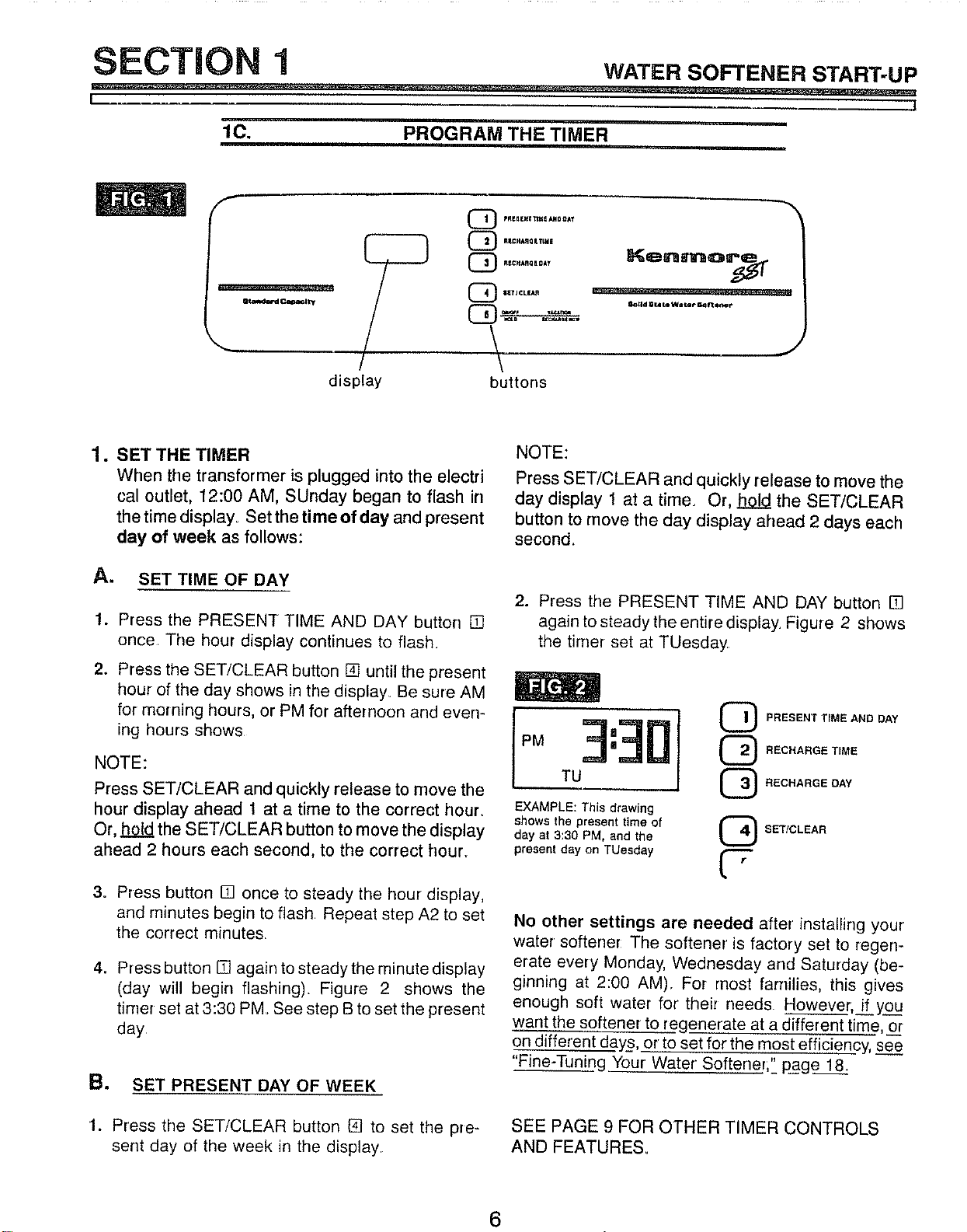
1. SET THE TIMER
When the transformer isplugged into the electri
cal outlet, 12:00 AM, SUnday began to flash in
the time display° Set thetime of day and present
day of week as follows:
A. SET TIME OF DAY
1. Press the PRESENT TIME AND DAY button []
once. The hour display continues to flash.
2. Press the SET/CLEAR button [] until the present
hour of the day shows in the display_ Be sure AM
for morning hours, or PM for afternoon and even-
ing hours shows
NOTE:
Press SET/CLEAR and quickly release to move the
hour display ahead 1 at a time to the correct hour.
Or, hold the SET/CLEAR button to move the display
ahead 2 hours each second, to the correct hour°
3o Press button [] once to steady the hour display,
and minutes begin to flash Repeat step A2 to set
the correct minutes,
4. Pr ess button [] again to steady the minute display
(day will begin flashing). Figure 2 shows the
timer set at 3:30 PM See step B to set the present
day
B. SET PRESENT DAY OF WEEK
1. Press the SET/CLEAR button [] to set the pre-
sent day of the week in the display
NOTE:
Press SET/CLEAR and quickly release to move the
day display 1 at a time. Or, hold the SET/CLEAR
button to move the day display ahead 2 days each
second.
2. Press the PRESENT TIME AND DAY button []
again to steady the entire display. Figure 2 shows
the timer set at TUesday.
[,, 3:181
PM : @ REC.ARGET,.E
mu @ RECHARGE DAY
EXAMPLE: This drawing
shows the present time of
day at 3:30 PM, and the
L_.2J
present day on TUesday t'-"-"
L"
SET/CLEAR
No other settings are needed after installing your
water softener The softener is factory set to regen-
erate every Monday, Wednesday and Saturday (be-
ginning at 2:00 AM). For most families, this gives
enough soft water for their needs However, if you
want the softener to regenerate at a different time, or
on different day_s,_orto set for the most efficiency, see
"Fine-Tuni_ng Your Water Softener;" page 18.
SEE PAGE 9 FOR OTHER TIMER CONTROLS
AND FEATURES.
6
SECTION 1 WATER SOFTENER START-UP
-- ,,1
I I
1D. SANITIZING THE WATER SOFTENER
Care is taken at the factory to keep your water
softener clean and sanitary. Materials used to make
the softener will not infect or contaminate your water
supply, and will not cause bacteria to form or grow.
However, during shipping, storage, installing and
operating, bacteria could get into the softener. For
this reason, sanitizing as follows is suggestedQ
when installing.
1
m
w
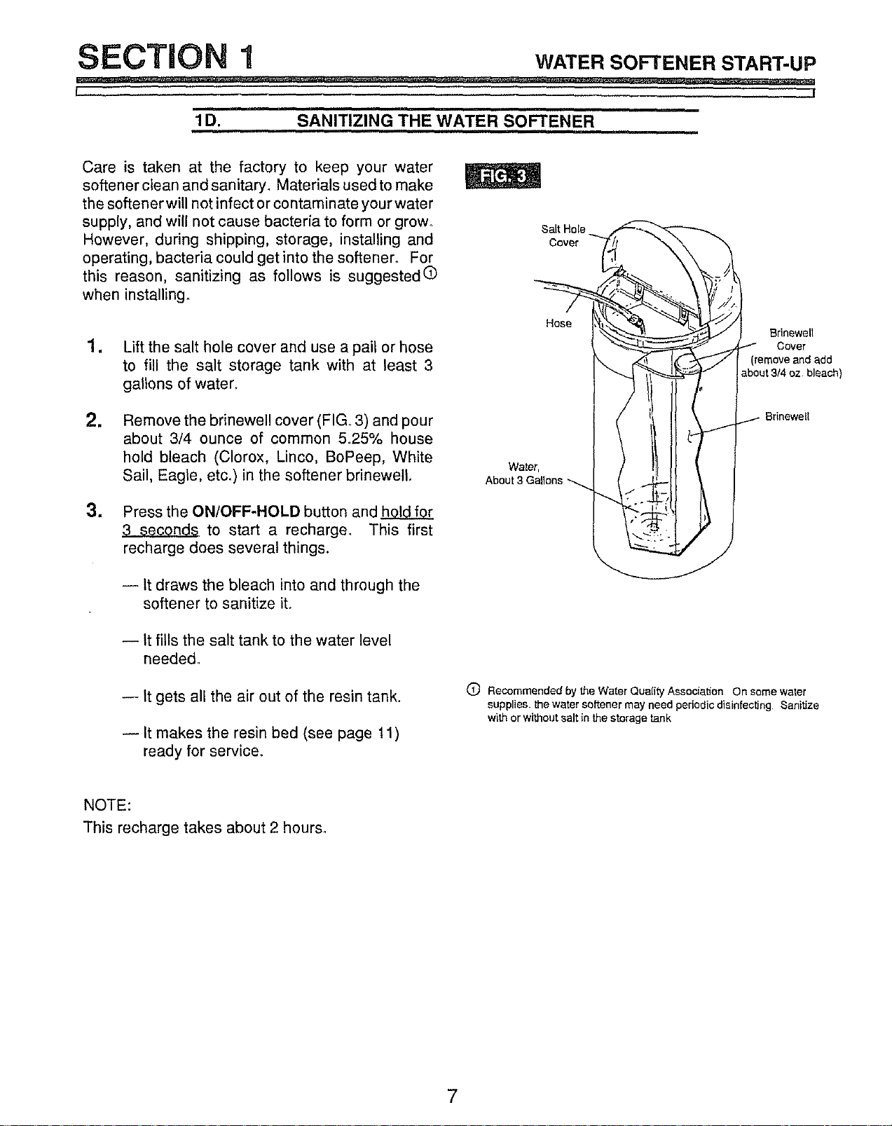
Lift the salt hole cover and use a pail or hose
to fill the salt storage tank with at least 3
gallons of water.
Remove the brinewell cover (FIG. 3) and pour
about 3/4 ounce of common 5.25% house
hold bleach (Clorox, Linco, BoPeep, White
Sail, Eagle, etc.) in the softener brinewetL
Press the ON/OFF-HOLD button and hol_ for
to start a recharge. This first
recharge does several things.
-- It draws the bleach into and through the
softener to sanitize it.
SaLt Hole
Cover
Hose
Water,
About 3 Gallons -_
Brinewell
Cover
(remove and add
about3/4 oz bleach)
--Itfitlsthe salttanktothe waterlevel
needed_
-- It gets all the air out of the resin tank.
-- It makes the resin bed (see page 11)
ready for service°
O Recommended by the Water Quality Association On some water
supplies, the water softener may need periodic disinfecting Sanitize
with or without salt in the storage tank
NOTE:
This recharge takes about 2 hours.
7
SECTION 1 wATERSOrrE.E.START-UP
L J
1E. FILL THE STORAGE' TANK WITH SALT ,,
Brine (salt dissolved in water) is needed for each and
every regeneration. The water for making brine is
metered into the salt storage tank by the softener.
However, you must keep the tank filled with salt.
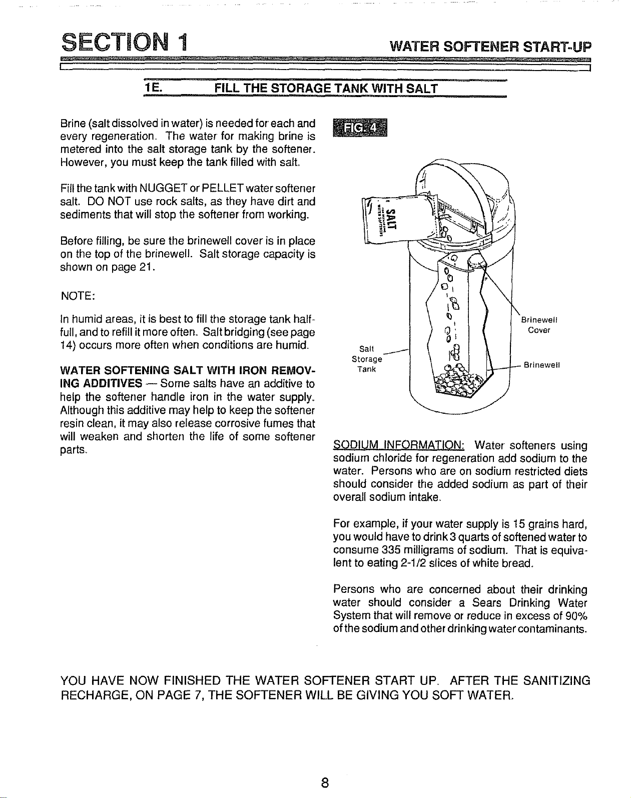
Fill the tank with NUGGET or PELLET water softener
salt. DO NOT use rock salts, as they have dirt and
sediments that will stop the softener from working.
Before filling, be sure the brinewell cover is in place
on the top of the brinewell. Salt storage capacity is
shown on page 21.
NOTE:
In humid areas, it is best to fill the storage tank half-
full, and to refill itmore often° Salt bridging (see page
14) occurs more often when conditions are humid.
WATER SOFTENING SALT WITH IRON REMOV-
ING ADDITIVES -- Some salts have an additive to
help the softener handle iron in the water supply°
Although this additive may help to keep the softener
resin clean, it may also release corrosive fumes that
will weaken and shorten the life of some softener
parts_
Salt
Storage
Tank
_ODIUM INFORMATION; Water softeners using
sodium chloride for regeneration add sodium to the
water. Persons who are on sodium restricted diets
should consider the added sodium as part of their
overall sodium intake.
For example, if your water supply is 15 grains hard,
you would have to drink 3 quarts of softened water to
consume 335 milligrams of sodium. That is equiva-
lent to eating 2-1/2 slices of white bread.
Persons who are concerned about their drinking
water should consider a Sears Drinking Water
System that will remove or reduce in excess of 90%
of the sodium and other drinking water contaminants.
YOU HAVE NOW FINISHED THE WATER SOFTENER START UPo AFTER THE SANITIZING
RECHARGE, ON PAGE 7, THE SOFTENER WILL BE GIVING YOU SOFT WATER_
8
SECTRON 2 .owYourwATERSO TE.E.WO.KS
I ]
i
2A. FACE PLATE TIMER FEATURES
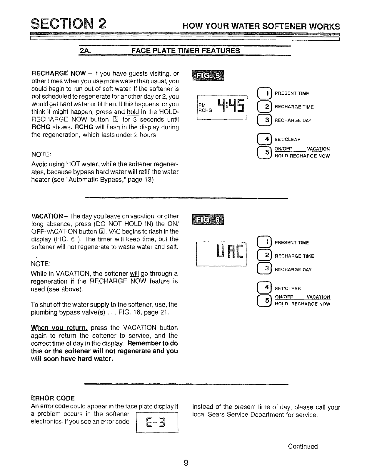
RECHARGE NOW - If you have guests visiting, or
other times when you use more water than usual, you
could begin to run out of soft water If the softener is
net scheduled to regenerate for another day or 2, you
would get hard water until then If this happens, or you
think it might happen, press and hold in the HOLD-
RECHARGE NOW button [] for 3 seconds until
RCHG shows RCHG wil! flash in the display during
the regeneration, which lasts under 2 hours
NOTE:
Avoid using HOT water, while the softener regener-
ates, because bypass hard water will refill the water
heater (see "Automatic Bypass," page 13).
PRESENT TIME
IOCE-
RECHARGE DAY
SET/CLEAR
ON/OFF VACATION
HOLD RECHARGE NOW
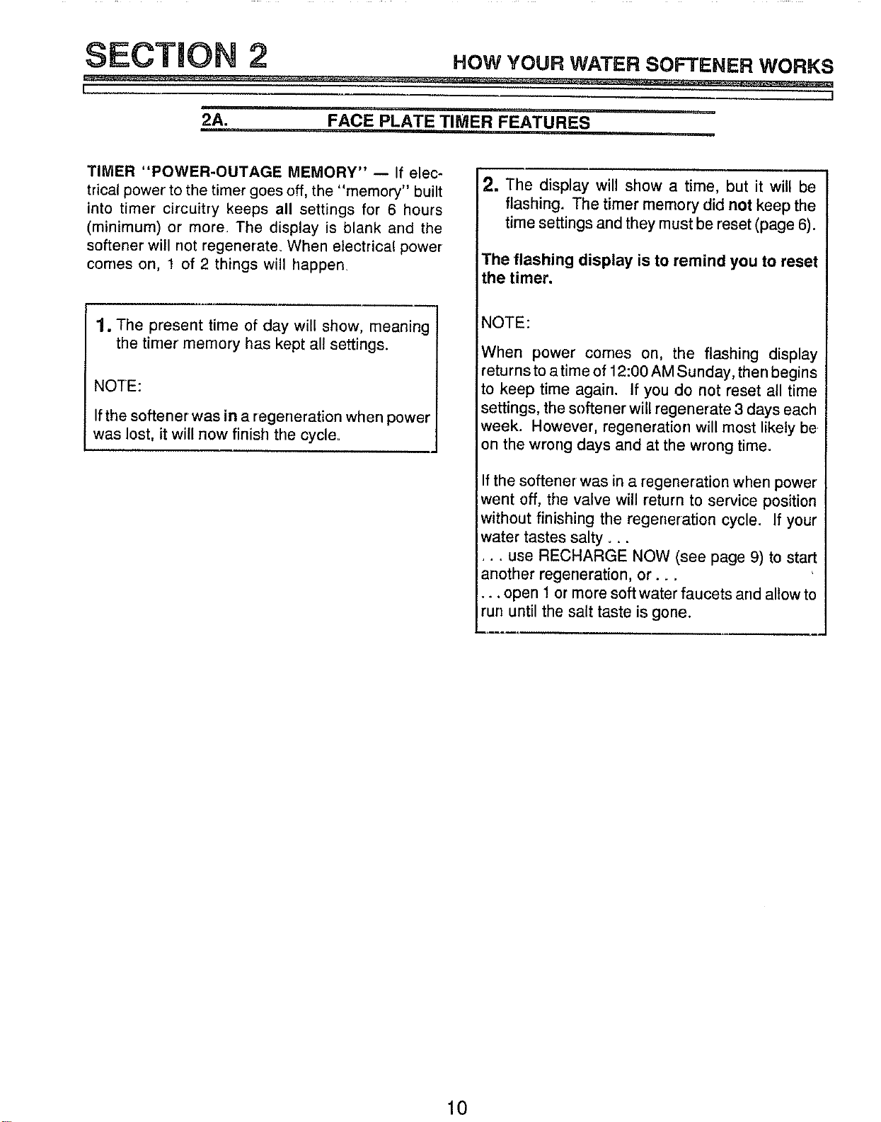
VACATION - The day you leave on vacation, or other
long absence, press (DO NOT HOLD IN) the ON/
OFF-VACATION button @ VAC begins to flash in the
display (FIG. 6 ) The timer will keep time, but the
softener will not regenerate to waste water and salt
NOTE:
While in VACATION, the softener wil___lgo through a
regeneration if the RECHARGE NOW feature is
used (see above)_
To shut off the water supply to the softener, use, the
plumbing bypass valve(s) .... FIG_ 16, page 21.
When you return_ press the VACATION button
again to return the softener to service, and the
correct time of day in the display° Remember to do
this or the softener will not regenerate and you
will soon have hard water.
RE
G PRESENT TIME
RECHARGE TIME
RECHARGE DAY
SET/CLEAR
ON/OFF VACATION
HOLD RECHARGE NOW
ERROR CODE
An error code could appear in the face plate display if
a problem occurs in the softener t
electronics. Ifyou see an error code !_ = _!
l
instead of the present time of day, please call your
local Sears Service Department for service
Continued
9
SECTION 2 .ow You.wATE.SOFrE.E.WO.KS
t .._J
2A. FACE PLATE TIMER FEATURES
TIMER "POWER-OUTAGE MEMORY" -- If elec-
trical power to the timer goes off, the "memory" built
into timer circuitry keeps all settings for6 hours
(minimum) or more, The display is blank and the
softener will not regenerate_ When electrical power
comes on, 1 of 2 things will happen,
1. The present time of day will show, meaning
the timer memory has kept all settings.
NOTE:
If the softener was in a regeneration when power
was lost, it will now finish the cycle=
, ,n
2. The display will show a time, but it will be
flashing. The timer memory did not keep the
time settings and they must be reset (page 6).
The flashing display is to remind you to reset
the timer.
NOTE:
When power comes on, the flashing display
returns to a time of 12:00 AM Sunday, then begins
to keep time again. If you do not reset all time
settings, the softener will regenerate 3 days each
week. However, regeneration will most likely be
on the wrong days and at the wrong time.
If the softener was in a regeneration when power
went off, the valve will return to service position
without finishing the regeneration cycle. If your
water tastes salty. _.
•.. use RECHARGE NOW (see page 9) to start
another regeneration, or. _
•.. open 1 or more soft water faucets and allow to
run until the salt taste is gone.
10
SECTION 2 .ow YOUR WATER SOFTENER WORKS
I ]
2B. SOFT WATER SERVICE, AND REGENERATION
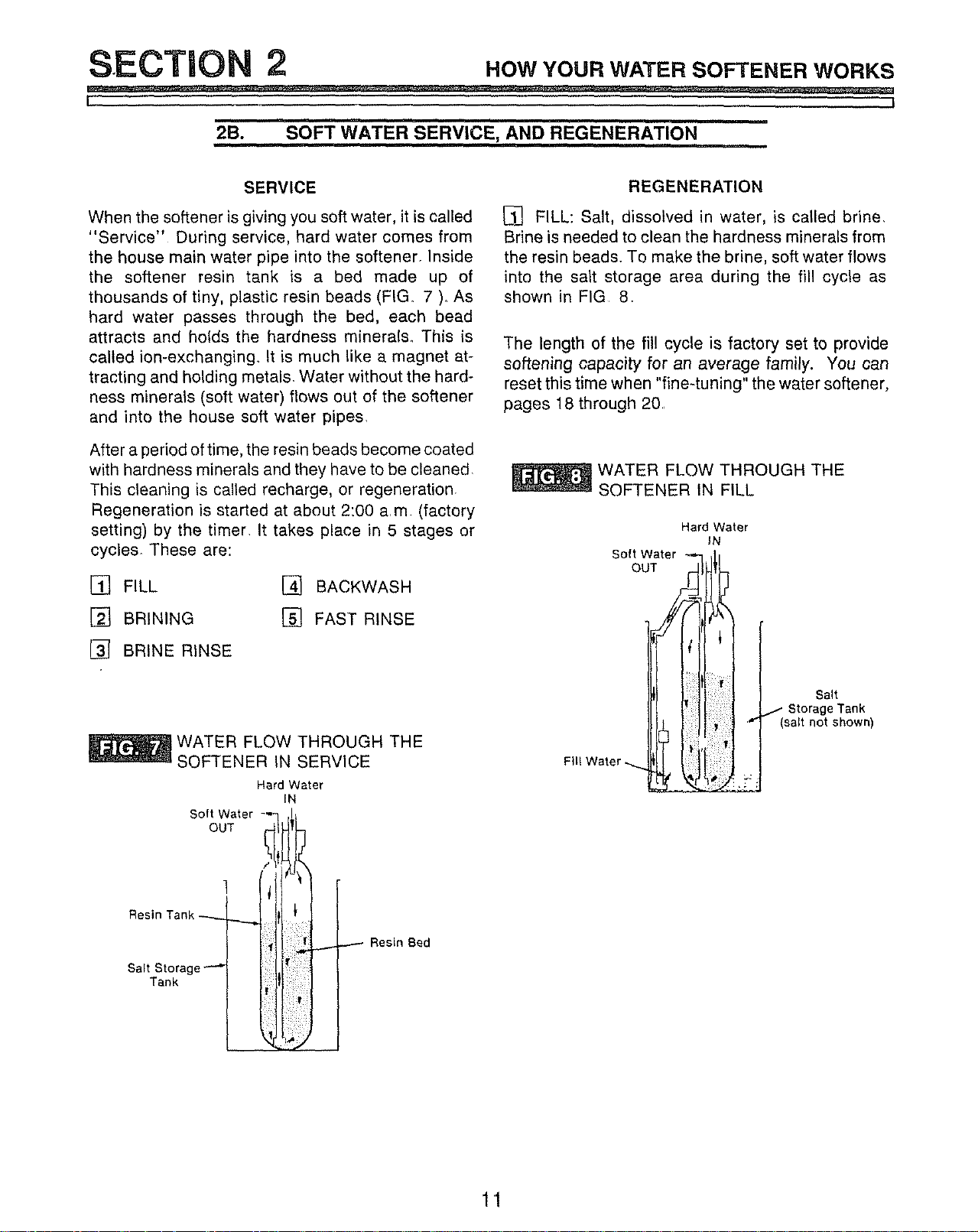
SERVICE
When the softener is giving you soft water, it is called
"Service" During service, hard water comes from
the house main water pipe into the softener. Inside
the softener resin tank is a bed made up of
thousands of tiny, plastic resin beads (FIG. 7 ). As
hard water passes through the bed, each bead
attracts and holds the hardness minerals This is
called ion-exchanging. It is much like a magnet at-
tracting and holding metals. Water without the hard-
ness minerals (soft water) flows out of the softener
and into the house soft water pipes.
After a period of time, the resin beads become coated
with hardness minerals and they have to be cleaned
This cleaning is called recharge, or regeneration.
Regeneration is started at about 2:00 a.m. (factory
setting) by the timer It takes place in 5 stages or
cyctes. These are:
[] FILL [] BACKWASH
[] BRINING [] FAST RINSE
[] BRINE RINSE
Soft Water
OUT
]
Resin Tank _
Salt Storage
Tank
WATER FLOW THROUGH THE
SOFTENER IN SERVICE
Hard Water
IN
Resin Bed
REGENERATION
[] FILL: Salt, dissolved in water, is called brine.
Brine is needed to clean the hardness minerals from
the resin beads. To make the brine, soft water flows
into the salt storage area during the fill cycle as
shown in FIG 8.
The length of the fill cycle is factory set to provide
softening capacity for an average family. You can
reset this time when "fine4uning" the water softener,
pages 18 through 20,
WATER FLOW THROUGH THE
SOFTENER IN FILL
Hard Water
JN
Soft Water
._.
,,Woter._j
Salt
.t- Storage Tank
(salt not shown)
11
SECTION 2 HowYourWATERSOFrE.ERWORKS
L j
2B. SOFT WATER SERVICE, AND REGENERATION
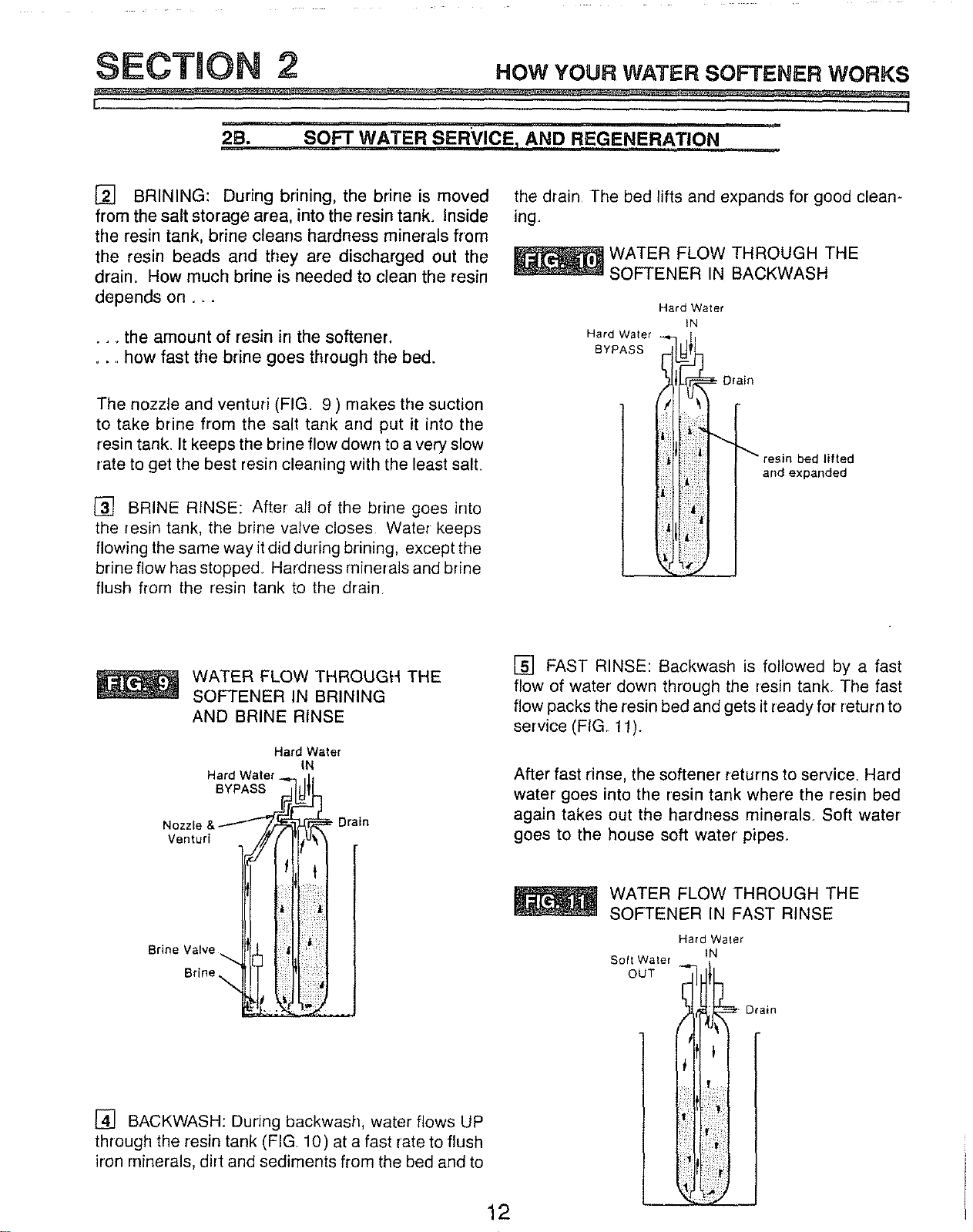
[] BRINING: During brining, the brine is moved
from the salt storage area, into the resin tank. Inside
the resin tank, brine cleans hardness minerals from
the resin beads and they are discharged out the
drain. How much brine is needed to clean the resin
depends on _..
... the amount of resin in the softener,
.... how fast the brine goes through the bed.
The nozzle and venturi (FIG. 9 ) makes the suction
to take brine from the salt tank and put it into the
resin tank. It keeps the brine flow down to a very slow
,ate to get the best resin cleaning with the least salt
[] BRINE RINSE: After all of the brine goes into
the resin tank, the brine valve closes Water keeps
flowing the same way it did during brining, except the
brine flow has stopped. Hardness minerals and brine
flush from the resin tank to the drain
the drain The bed lifts and expands for good cleam
ing
WATER FLOW THROUGH THE
SOFTENER IN BACKWASH
Hard Water
IN
Hard Water
BYPASS
d lifted
and expanded
WATER FLOW THROUGH THE
SOFTENER IN BRINING
AND BRINE RINSE
Hard Water
IN
Brine Valve _t__] 'l[ill
Brine
[] BACKWASH: During backwash, water flows UP
through the resin tank (FIG 10) at a fast rate to flush
iron minerals, dirt and sediments from the bed and to
12
[] FAST RINSE: Backwash is followed by a fast
flow of water down through the resin tank. The fast
flow packs the resin bed and gets it ready for return to
service (FIG 11).
After fast rinse, the softener returns to service. Hard
water goes into the resin tank where the resin bed
again takes out the hardness minerals. Soft water
goes to the house soft water pipes.
WATER FLOW THROUGH THE
SOFTENER IN FAST RINSE
Hard Water
IN
Soft Water
; . Drain
i:
SECTION 2 .ow YOUR WATER SOFTENER WORKS
! j
2B. SOFT WATER SERVICE, AND REGENERATION
AUTOMATIC BYPASS
During the brining, brine rinse and backwash cycles
of regeneration, HARD water goes through the soft-
ener valve and to the house pipes, If a faucet is
opened, hard water is there for your needs How-
ever, you should not use HOT water, if possible,
because the water heater will refill with hard water
The softener regenerates from 2:00 AM to about
4:00 AM, (you can set anytime), a time when not
much water is used_
tf you get up early in the morning and you can hear
the softener regenerating, change the time setting,
Set the recharge time to 12:00 AM or 1:00 AM (page
18), Then regeneration will start and end that much
earlier and your water heater will not refill with hard
water if a hot faucet is opened,
13
SECTION 3 cAREoFYOURsoFrE.ER
f J
i
3A. SALT... REFILLING STORAGE TAN_BREAKING A SALT BRIDGE
WHEN TO REFILL WITH SALT: Check the salt level
a few weeks after you install the softener and every
week after that. Refill when the storage tank is about
1/3 full. Never let the softener use all the salt before
refilling. Without salt, you will soon have hard water.
NOTE:
You will have a loss in softening capacity and may get
partly hard water if less than 10 inches of salt is in
the storage tank_
PLEASE SEE PAGE 8 FOR SALT FILLING DIRECTIONS.
SALT BRIDGE
Sometimes, a hard crust or salt bridge forms in the
salt storage tank. It is usually caused by high humidi-
ty or the wrong kind of sail When the salt bridges,
an empty space forms between the water and salt..
Then salt will not dissolve (melt) in the water to make
brine Without brine, the resin bed does not
regenerate and you will have hard water.
If the storage tank is full of salt, it is hard to tell if
you have a salt bridge Salt is loose on top, but the
bridge is under it. The following is the best way to
check for a salt bridge.
POUNDING ON THE OUTSIDE OF THE SALT TANK.
YOU MAY DAMAGE iT.
If the wrong kind of salt made the bridge, take it out.
Then fill the tank with nugget or pellet salt only,
A SAL-f BRIDGE
Pushtoolintosalt
bridge to break
Pencil
Mark
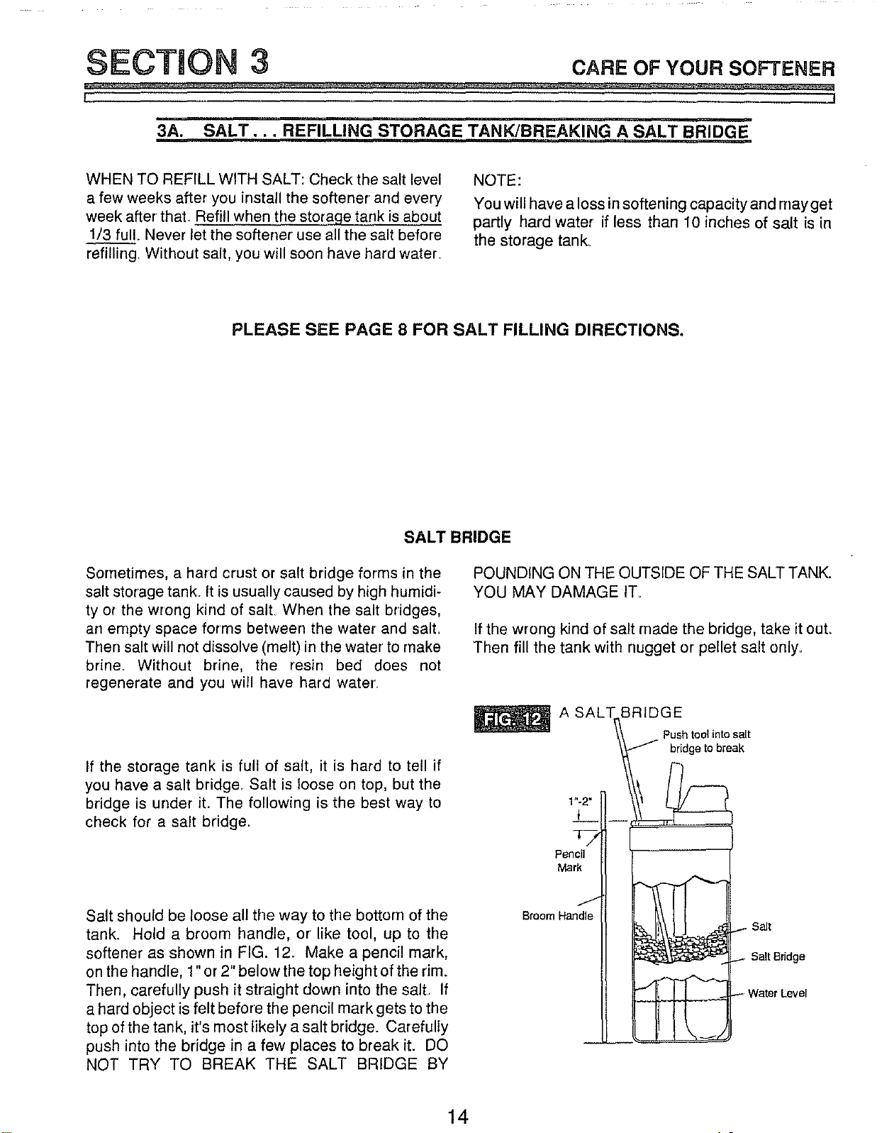
Salt should be loose all the way to the bottom of the
tank. Hold a broom handle, or like tool, up to the
softener as shown in FIG. 12. Make a pencil mark,
on the handle, 1" or 2" below the top height of the rim.
Then, carefully push it straight down into the salt. If
a hard object is felt before the pencil mark gets to the
top of the tank, it's most likely a salt bridge. Carefully
push into the bridge in a few places to break it. DO
NOT TRY TO BREAK THE SALT BRIDGE BY
Broom Handle
salt
Bait Bridge
Nater Level
14
SECTION 3 CA.EoFYoursoFrE.ER
I
i i .11 .i i . .. lit IM i
3B. KEEPING THE WATER SOFTENER CLEAN
COVERS
To keep your new Sears water softener looking nice,
apply a coat of paste wax and repeat once a year.
When dusty, wipe it With a damp cloth to keep it
sparkling
NOTE:
Never use cleaners having ammonia or abrasives.
They may scratch and dull the surface,
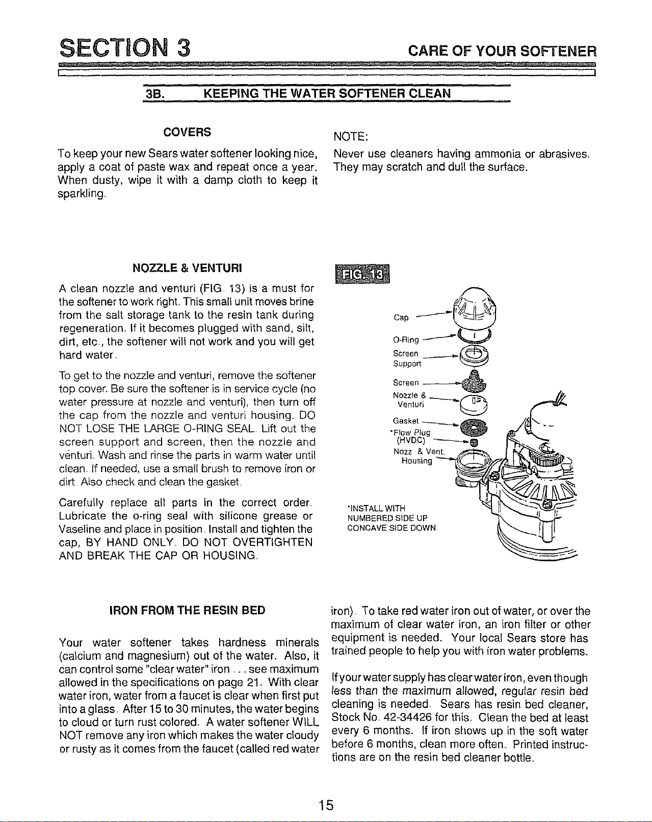
NOZZLE & VENTURI
A clean nozzle and venturi (FIG 13) is a must for
the softener to work right This small unit moves brine
from the salt storage tank to the resin tank during
regeneration. If it becomes plugged with sand, silt,
dirt, etc, the softener will not work and you will get
hard water.
To get to the nozzle and venturi, remove the softener
top cover Be sure the softener is in service cycle (no
water pressure at nozzle and venturi), then turn off
the cap from the nozzle and venturi housing. DO
NOT LOSE THE LARGE O-RING SEAL Lift out the
screen support and screen, then the nozzle and
venturi. Wash and rinse the parts in warm water until
clean. If needed, use a small brush to remove iron or
dirt Also check and clean the gasket.
Carefully replace all parts in the correct order
Lubricate the o-ring seal with silicone grease or
Vaseline and place in position Install and tighten the
cap, BY HAND ONLY. DO NOT OVERTIGHTEN
AND BREAK THE CAP OR HOUSING.
"INSTALL WITH
NUMBERED SIDE UP
CONCAVE SIDE DOWN
IRON FROM THE RESIN BED
Your water softener takes hardness minerals
(calcium and magnesium) out of the water. Also, it
can control some "clear water" iron .... see maximum
allowed in the specifications on page 21. With clear
water iron, water from a faucet is clear when first put
into a glass After 15 to 30 minutes, the water begins
to cloud or turn rust colored° A water softener WILL
NOT remove any iron which makes the water cloudy
or rusty as it comes from the faucet (called red water
iron) To take red water iron out of water, or over the
maximum of clear water iron, an iron filter or other
equipment is needed. Your local Sears store has
trained people to help you with iron water problems.
If your water supply has clearwater iron, even though
less than the maximum allowed, regular resin bed
cleaning is needed. Sears has resin bed cleaner,
Stock No. 42-34426 for this. Clean the bed at least
every 6 months. If iron shows up in the soft water
before 6 months, clean more often Printed instruc-
tions are on the resin bed cleaner bottle.
15
SECTION 3 cA.EoryourSO E.E.
t i
i ii
3C. KEEP THE SOFTENER FROM FREEZING
If the softener is installed where it could freeze (sum-
mer cabin, lake home, etc.), you must drain all water
from it to stop possible freeze damage_ To drain the
softener --
1. Close the shut-off valve on the house main water
pipe, near the water meter or pressure tank_
2. Open a faucet in the soft water pipes to vent
pressure in the softener,
1
Looking at FIG. 16 on page 21, move the stem in
a single bypass valve to bypass. Close the inlet
and outlet valve in a 3-valve bypass system, and
open the bypass valve. If you want water in the
house pipes again, reopen the shut-off valve on
the main water pipe.
4. Unplug the transformer at the walt outlet. Remove
the salt hole cover and the main cover. Take off
both drain hoses.
=
Carefully remove the large holding clips at the
softener inlet and outlet (see Key No. 61,
on page 34). Separate the softener from the
adaptors or bypass valve.
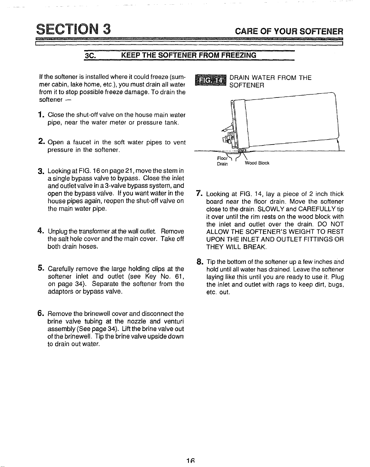
DRAIN WATER FROM THE
SOFTENER
Drain
Wood Block
J
Q
1
Looking at FIG 14, lay a piece of 2 inch thick
board near the floor drain. Move the softener
close to the drain_ SLOWLY and CAREFULLY tip
it over until the rim rests on the wood block with
the inlet and outlet over the drain. DO NOT
ALLOW THE SOFTENER'S WEIGHT TO REST
UPON THE INLET AND OUTLET FITTINGS OR
THEY WILL BREAK.
Tip the bottom of the softener up a few inches and
hold until all water has drained, Leave the softener
laying like this until you are ready to use iL Plug
the inlet and outlet with rags to keep dirt, bugs,
etc. out,
w Remove the brinewell cover and disconnect the
brine valve tubing at the nozzle and venturi
assembly (See page 34). Lift the brine valve out
ofthe brinewell. Tip the brine valve upside down
to drain out water.
1R
SECTION 3 CAREoFYourSOn'E.ER
L l
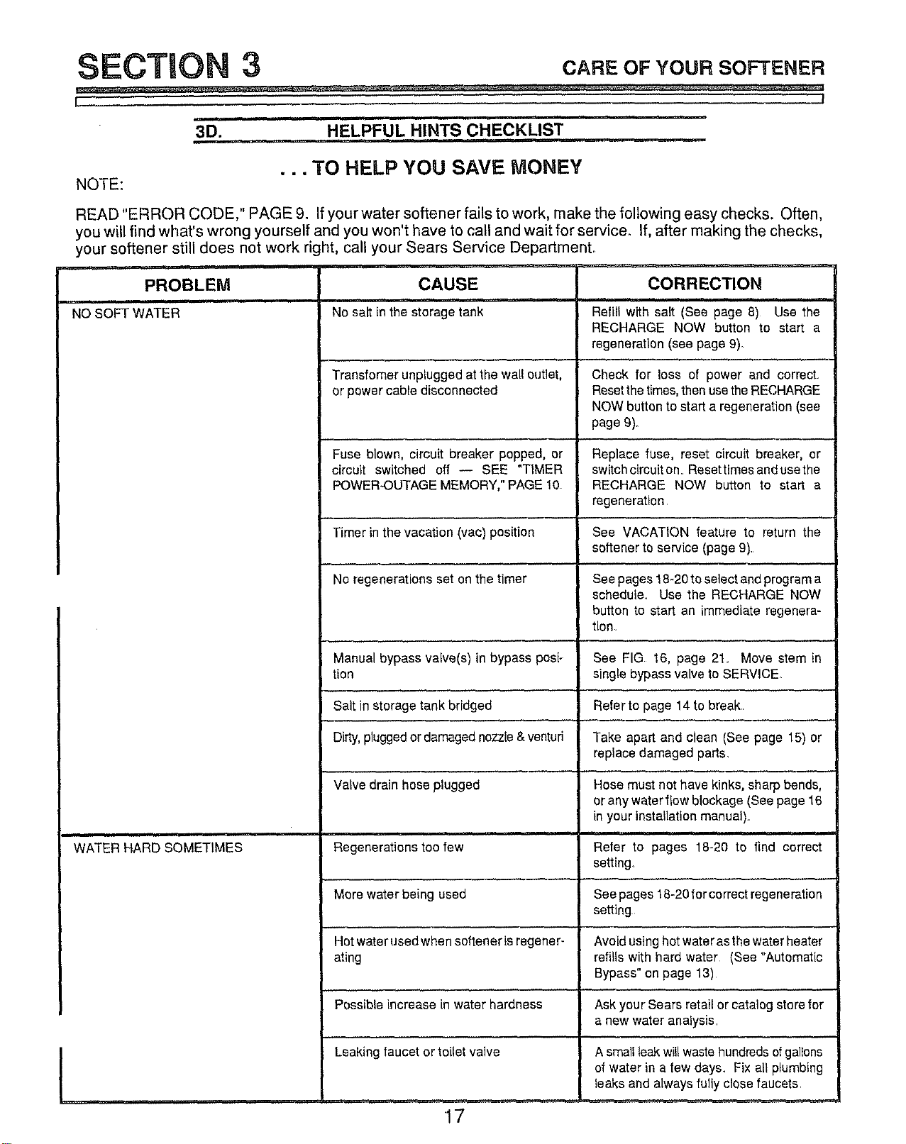
3D, HELPFUL HINTS CHECKLIST
NOTE:
• • •TO HELP YOU SAVE MONEY
READ "ERROR CODE," PAGE 9. Ifyour water softener fails to work, make the following easy checks. Often,
you will find what's wrong yourself and you won't have to call and wait for service. If, after making the checks,
your softener still does not work right, call your Sears Service Department_
, i,rl_
PROBLEM CAUSE CORRECTION
NOSOFT WATER No salt in the storage tank
WATER HARD SOMETIMES
Transfomer unplugged at the walloutlet,
or power cable disconnected
Fuse blown, circuit breaker popped, or
circuit switched off -- SEE "TIMER
POWER-OUTAGEMEMORY,"PAGE 10
Timer inthe vacation (vac) position
No regenerations set on the timer
Manual bypass valve(s) in bypass posi_
tion
Salt in storage tank bridged
Dirty,pluggedordamagednozzle&venturi
Valve drain hose plugged
, m.,
Regenerations too few
More water being used
Hot water usedwhen softener isregener-
ating
Possibleincrease in water hardness
Leaking faucet or toilet valve
Refill with salt (See page 8) Use the
RECHARGE NOW button to start a
regeneration (see page 9)
Check for loss of power and correct
Resetthetimes,thenusetheRECHARGE
NOW button to start a regeneration (see
page9).
Replace fuse, reset circuit breaker, or
switchcircuit on. Resettimes and usethe
RECHARGE NOW button to start a
regeneration
See VACATION feature to return the
softener to service (page 9).
See pages 18-20to select andprograma
schedule. Use the RECHARGE NOW
button to start an immediateregenera-
tion.
See FIG 16, page 21. Move stem in
single bypass valve to SERVICE
Refer to page 14to break.
Take apart and clean (See page 15) or
replace damaged parts.
Hose must not have kinks, sharp bends,
or anywater flowblockage (See page 16
in your installation manual).
Refer to pages 18-20 to find correct
setting.
See pages18-20forcorrect regeneration
setting
Avoid usinghotwater asthe water heater
refills with hard water (See "Automatic
Bypass" on page 13)
Ask your Sears retail or catalog store for
a new wateranalysis
A smatlleakwillwastehundredsofgallons
of Water ina few days Fix all plumbing
leaks and always fully close faucets
17

SECTION 4 oT. . T.I.GsToK.ow
L !
4A. HOW TO "FINE-TUNE" YOUR SOFTENER
i................
It is not hard to fine-tune your softener, but it does
take a few minutes of your time to do it righL You
may save up to 500 pounds or more of salt each year
with proper tuning° Read the following carefully.
To have soft water all the time, the softener must
regenerate, or recharge a certain number of times in
each 7 day period How many times to regenerate
(set on the timer) depends on 3 things.
1. The number of people in your' home -- tells you
how much water is used.
2. The grains per gallon (GPG) hardness of your
water supply -- listed on your water analysis
report .... see page 2 in your Installation Manual,
or page 2 of this manual.
NOTE:
If your water supply contains iron, compensate for it
by adding to the water hardness number. For ex-
ample, assume your water is 15 gpg hard and con-
tains 2 ppm iron° Add5 to the hardness number for
each I ppm of#on. In this example, you would use
25 for your hardness number.
15 gpg hardness
2ppmiron x 5=10
(times) 25 HARDNESS NUMBER
3. How much salt is used each regeneration --
determined by the length of the fill cycle o. osee
pages 19 and 2&
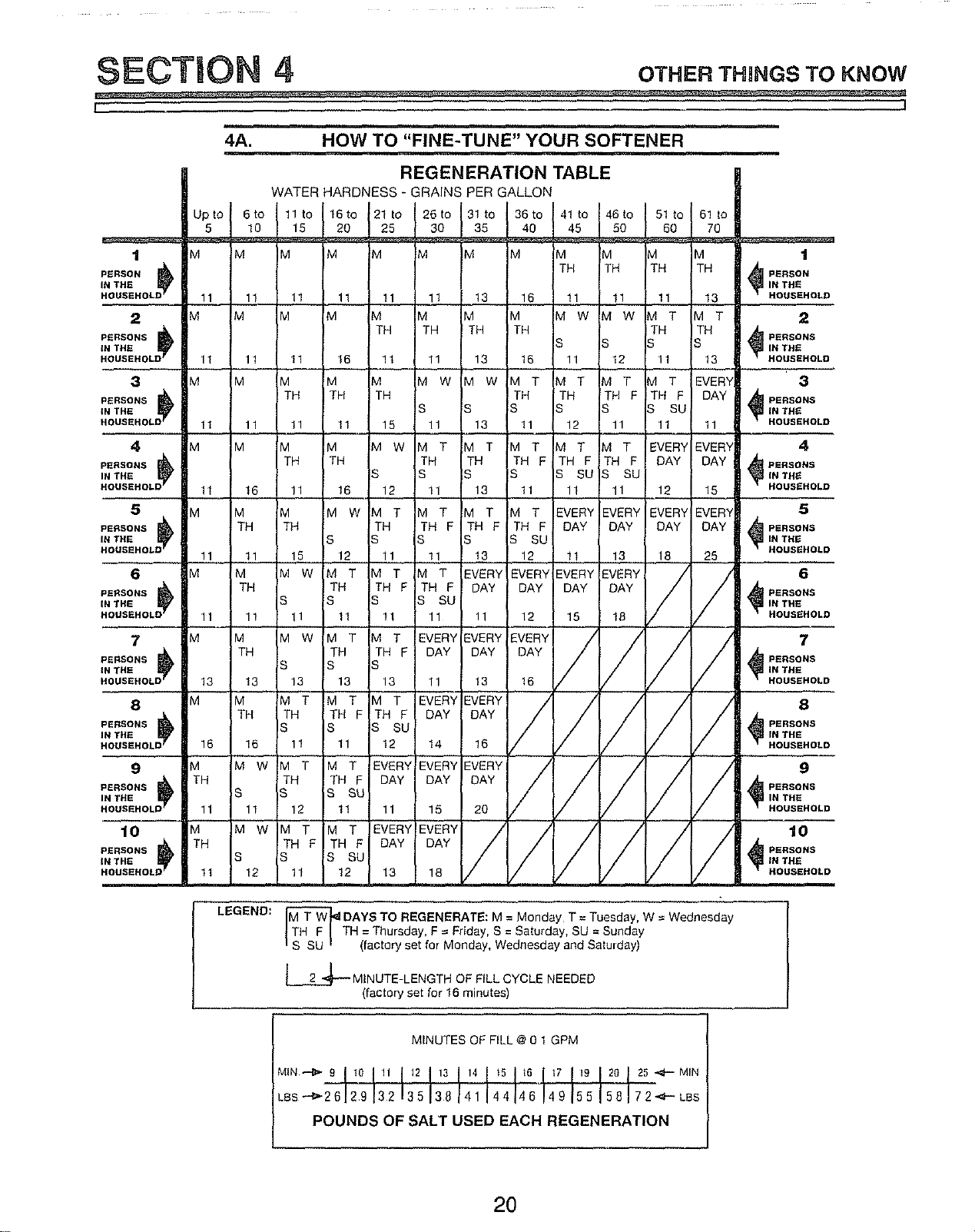
REGENERATION TABLE: The table (page 20)
makes it easy for you to pick the best regeneration
and fill time setting to use.
Step 1 -- Go down the side of the table, to the
number of persons in your family, or the number of
people in the house using water.
Step 2 -- Across the top of the table, find the col-
umn listing the grains per gallon hardness of your
water.
Step 3 -- Read across and down the table fo find [
the point where steps 1 and 2 meet. At this meeting
I
point, suggested days to regenerate, and fill cycle
minutes needed are shown_ _-----4_
TO SET THE TIMER FOR DAYS OF REGENERA-
TION, AND FILL MINUTES, DO THE FOLLOWING.
NOTE:
Remember, the timer is factory set for Monday,
Wednesday and Saturday regenerations starting at
2:00 A.M Fill time is factory set for 16 minutes.
lm
a.
SET DAYS AND TIME OF REGENERATION_
OR RECHARGE
Press the RECHARGE TIME button [] once, to
display the factory set regeneration days and
starting time (flashing). To change the regenera-
tion start time, do step b following, Otherwise go
to step c.
@
@
PRESENTT|ME A_
RECHARGETIME
RECHARGE DAY
NOTE:
Read "Automatic Bypass" page 13, when choosing
a regneration starting time other than 2:00 AM.
b. Press the SET/CLEAR button [] until the de-
sired regeneration starting time shows in the
display.
NOTE:
Press SET/CLEAR and quickly release to move the
display ahead 1 hour at a time. Or, _ the SET/
CLEAR button to move the display ahead 2 hours
each second.
WRITE IN YOUR RESULTS HERE.
1. M T W TH F S SU Suggested days to
-circle suggested days- regenerate
2. __Fill Cycle minutes needed
18
SECTION 4 oT.E.T.I.GSTOK.OW
L J
4A. HOW TO "FINE-TUNE" YOUR SOFTENER
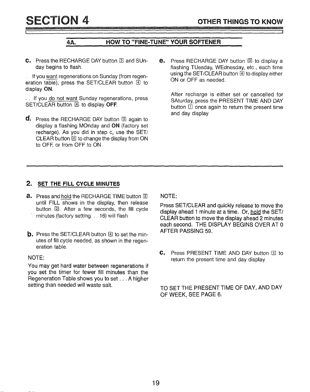
C. Press the RECHARGE DAY button [] and SUn-
day begins to flash,
.... If you want regenerations on Sunday (from regen-
eration table), press the SET/CLEAR button [] to
display ON,
, ,if you do not want Sunday regenerations, press
SET/CLEAR button [] to display OFE
d,*
Press the RECHARGE DAY button [] again to
display a flashing MOnday and ON (factory set
recharge), As you did in step c, use the SET/
CLEAR button [] to change the display from ON
to OFF, or from OFF to ON
e.
Press RECHARGE DAY button [] to display a
flashing TUesday, WEdnesday, etc, each time
using the SET/CLEAR button _ to display either
ON or OFF as neede&
After recharge is either set or cancelled for
SAturday, press the PRESENT TIME AND DAY
button [] once again to return the present time
and day display
2. SET THE FILL CYCLE MINUTES
a. Press and hold the RECHARGE TIME button []
until FILL shows in the display, then release
button [] After a few seconds, the fill cycle
" minutes (factory setting,,, 16) will flash
b. Press the SET/CLEAR button [] to set the min-
utes of fill cycle needed, as shown in the regen-
eration table_
NOTE:
You may get hard water between regenerations if
you set the timer for fewer fill minutes than the
Regeneration Table shows you to set _., A higher
setting than needed will waste salt.
NOTE:
Press SET/CLEAR and quickly release to move the
display ahead 1 minute at a time. Or. hold the SET/
CLEAR button to move the display ahead 2 minutes
each second. THE DISPLAY BEGINS OVER AT 0
AFTER PASSING 59.
C. Press PRESENT TIME AND DAY button [] to
return the present time and day display,
TO SET THE PRESENT TIME OF DAY, AND DAY
OF WEEK, SEE PAGE 6,
•19
SECTION 4 oT.E.T.m.GSTOK.OW
[ ]
4A. HOW TO "FINE-TUNE" YOUR SOFTENER
REGENERATION TABLE
WATER HARDNESS - GRAINS PER GALLON
1 M M M IM M M
PERSON _ i
I
IN THE i
HOUSEHOLD' 11 11 11 11 !1
2 M M M 'M M
PERSONS D_ TH
IN THE
HOUSEHOL 11 11 11 1_ 11
[
3 M M M M M
PERSONSI_ TH TH TH
IN THE
HOUSEHOL 11 11 11 11 15
'l I
4 M M M ,M M W
_ERSDNSI_ TH TH
INTHE D_ S
HOUSSNOL 11 16 !1 16 12
M M M IM W
5
PERSONS D_
IN THE
HOUSEHOL
11
6
,i
PERSONS
IN THE
IODSEHOLO' 11
7
PERSONS _IN THE
HOUSEHOLD 13
8 M
PERSONS D_
IN THE
HOUSEHDL 16
9 M
PERSONSD_) TH
IN THE
HODSEHOL 11
10 M
PERSONSpJ_ TH
INTHE J
HOUSEHOL 11
TH TH
S
11 15 12
M M W M T
TH ! TH
S S
11 11 11
M M W !M T
TH I TH
S _S
13 13 13
M M 'T !M T
TH TH ' TH F
S ISll
16 11
M W MTHT TMHTF
S S S 11SU
11 12
M W M T M T
THE H F
S S S SU
12 11 12
M M rM M M M
ITH TH TH TH
1
_ PERSONIN THE
11 13 16 I 11 11 11 13 HOUSEHOLD
M M M M W M W M T M T 2
TH TH TH I TH TH ,_ PERSONS
=S S S _ _ IN THE
11 13 16 11 12 11 13 HOUSEHOLD
M W M W M T !M T M T M T EVERYJ 3
TH [sTH THE THF DAY _PERSONS
S S S S S SU IN THE
11 13 11 12 11 11 11 HOUSEHOLD
I
M T M T M T !M T M T EVERY EVERYi 4
ql
TH TH THF THF TH F DAY DAY I' _ PERSONS
S S S IS SU S SU _ IN THE
11 13 11 11 11 12 15 HOUSEHOLD
[
5
M T M T M T M T !EVERY EVERY EVERY EVER'_
TH THF I THF TH F DAY DAY DAY DAY _ PERSONS
S S S S SU _ IN THE
HOUSEHOLD
11 11 13 12 11 13 18 25
'Vl T M T EVERY EVERY -_-VERY EVERY / / _ 6
THF THF DAY DAY DAY DAY PERSONS
S S SU j IN THE
!1 11 11 12 15 1B HOUSEHOLD
T ,
THF DAY DAY DAY PERSONS
S IN THE
13 11 13 16 HOUSEHOLD
a T EVERY EVERY/ // / / _ 8
TH F DAY DAY
S SU PERSONS
IN THE
12 _4 16 HOUSEHOLD
........
EVERY EVERY EVERY / //
DAY DAY DAY PERSONS
IN THE
11 15 20 HOUSEHOLD
,o
DAY DAY PERSONS
IN THE
13 18 HOUSEHOLD
LEGEND:
DAYS TO REGENERATE: M = Monday, T = Tuesday, W = Wednesday
TH = Thursday, F = Friday, S = Saturday, SU = Sunday
{factory set for Monday, Wednesday and Saturday)
_MINUTE-LENGTH OF FILL CYCLE NEEDED
{factory set for 16 minutes)
MINUTES OF FILL @ 0 1 GPM
MIN _ 9 10 11 12 13 14
LBS-'I_26 29 32 13'5 38 41' 454 !6 117 119 1201 25-_-MIN
46 49155(581z2 -- B
POUNDS OF SALT USED EACH REGENERATION
20
SECTION 4 oT,E.r.i.GsToK.ow
I J
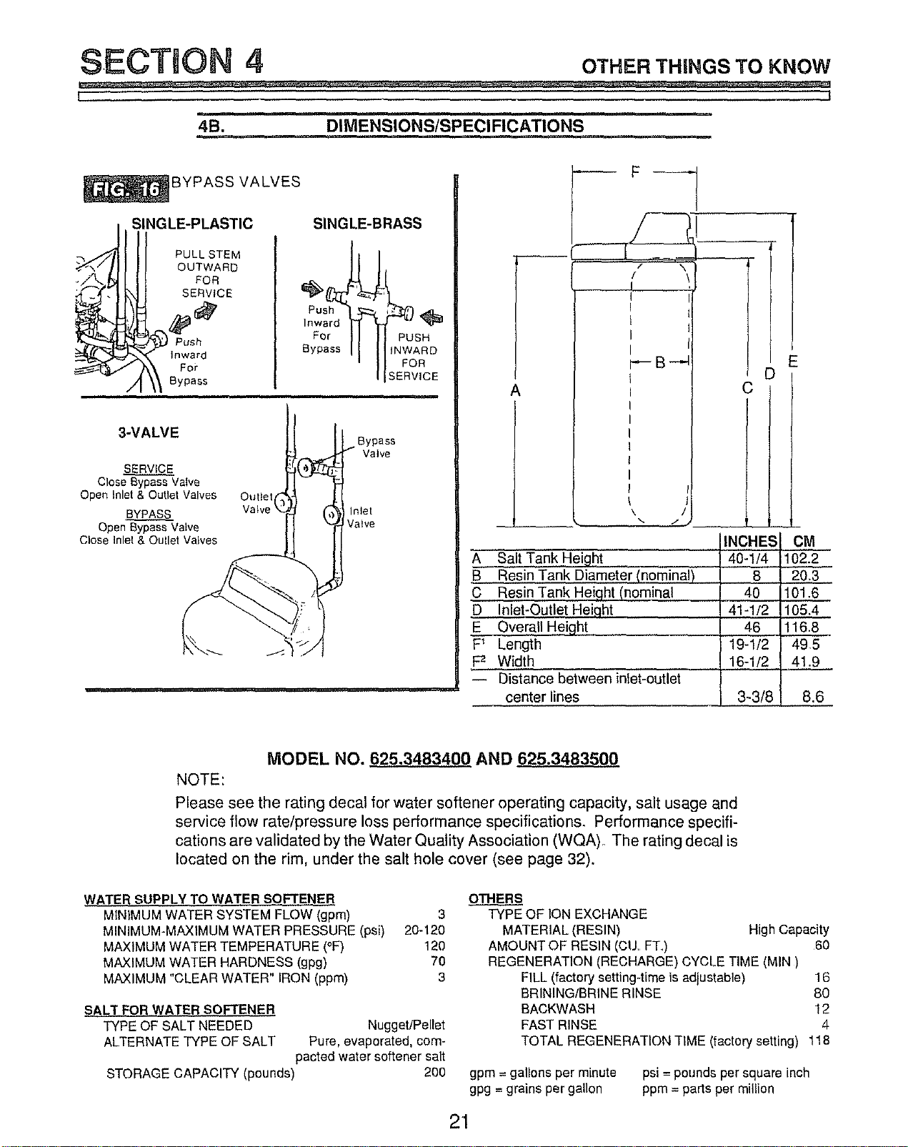
4B. DIMENSIONS/SPECIFICATIONS
_,YPASS VALVES
SINGLE-PLASTIC
PULL STEM
OUTWARD
FOR
SERVICE
SINGLE-BRASS
For PUSH
Bypass INWARD
FOR
SERVICE
3-VALVE
SERVICE
Close Bypass Valve
Open Inlet & Outlet Valves Outtel
BYPASS Inlet
Open Bypass Valve Valve
Close Inlet & Qullet Valves
Bypass
Valve
A
-- '1_
_S_
C
A Salt Tank Height
B Resin Tank Diameter (nominal)
C Resin Tank Heiqht (nominal
D Inlet-Outlet Heiqht
E Overall Height
F_ Length
F2 Width
-- Distance between inlet-outlet
center lines
iINCHES
40-1/4
8
40
I 41-1/2
46
19-1/;
E
CM
102,2
20.3
101,6
105.4
116.8
49.5
16-1/; 41.9
3-3/_ 8.6
MODEL NO. 625.3483400 AND 625.3483500
NOTE:
Please see the rating decal for water softener operating capacity, salt usage and
service flow rate/pressure loss performance specifications. Performance specifi-
cations are validated by the Water Quality Association (WQA)o The rating decal is
located on the rim, under the salt hole cover (see page 32).
WATEI_ SUPPLY TO WATER SOFTENER
MINIMUM WATER SYSTEM FLOW (gpm) 3
MINIMUM-MAXIMUM WATER PRESSURE (psi) 20-120
MAXIMUM WATER TEMPERATURE (oF) 120
MAXIMUM WATER HARDNESS (gpg) 70
MAXIMUM "CLEAR WATER" IRON (ppm) 3
SALT FOR WATER SOFTENER
TYPE OF SALT NEEDED Nugget/Pellet
ALTERNATE TYPE OF SALT Pure, evaporated, com-
pacted water softener salt
STORAGE CAPACITY (pounds) 200
OTHERS
TYPE OF ION EXCHANGE
MATERIAL (RESIN) High Capacity
AMOUNT OF RESIN (CtJ, FT) 60
REGENERATION (RECHARGE) CYCLE TIME (MIN)
FILL (factory setting-time is adjustable) 16
BRINING/BRINE RINSE 80
BACKWASH 12
FAST RINSE 4
TOTAL REGENERATION TIME (factory setting) 118
gpm =gallons per minute
gpg = grains per gallon
psi =pounds per square inch
ppm = parts per million
21
SECTION 5 SERWCER'STEC.INFORMATmON
t $
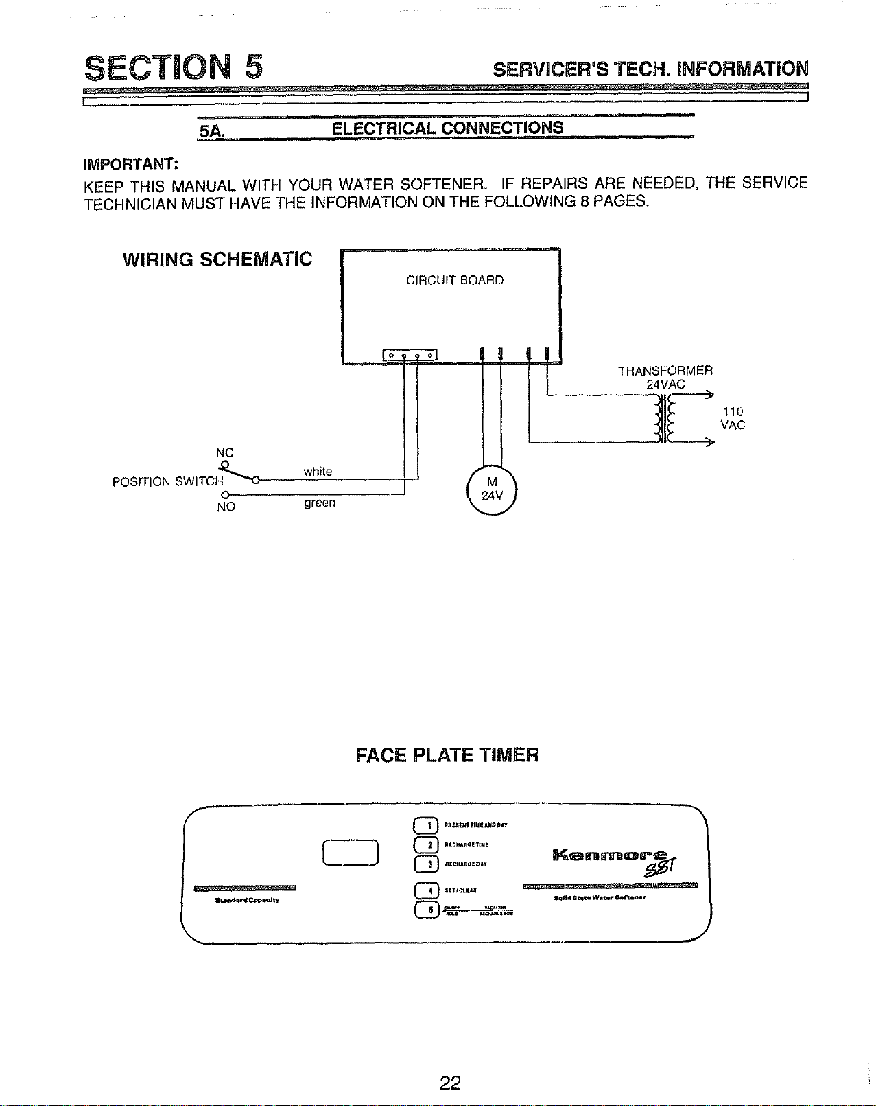
5A. ELECTRICAL CONNECTIONS
IMPORTANT:
KEEP THIS MANUAL WITH YOUR WATER SOFTENER. IF REPAIRS ARE NEEDED, THE SERVICE
TECHNICIAN MUST HAVE THE INFORMATION ON THE FOLLOWING 8 PAGES.
WIRING SCHEMATIC
NC
POSITION SWITCH-_'o white
O
NO green
CIRCUIT BOARD
__, I i
r
110
VAC
FACE PLATE TIMER
_, ,,,,
pnU_T_I4_8_A_
RI_RQIItU_
R_¢_aIOA T
Kemlmo_
22
SECTUON 5 SERVlCER'STECH.INFORMATION
L::: , I
. ....... ..it.
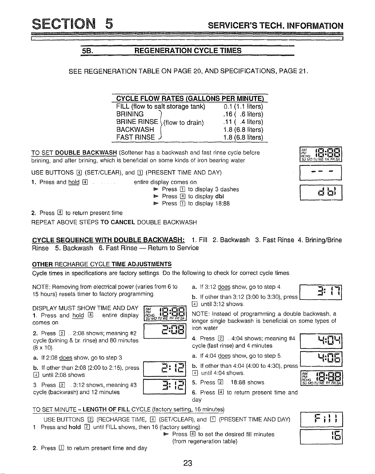
5B. REGENERATION CYCLE TIMES
SEE REGENERATION TABLE ON PAGE 20, AND SPECIFICATIONS, PAGE 21_
CYCLE FLOW RATES (GALLONS PER MINUTE)
FILL (flow to salt storage tank) 0,1 (1,1 liters)
BRINING "_ .16 ( .6 liters)
BRINE RINSE_(flow to drain) .11 ( ,,4liters)
BACKWASH _ 1o8(6,8 liters)
FAST RINSE -) 1.8 (6.8 liters)
TO SET DOUBLE BACKWASH (Softener has a backwash and fast rinse cycle before
brining, and after brining, which is beneficial on some kinds of iron bearing water
USE BUTTONS [] (SET/CLEAR), and [] (PRESENT TIME AND DAY)
1. Press and hol_dd[] ....
2. Press [] to return present time
entire display comes on
_,- Press [] to display 3 dashes
Press [] to display dbl
Press [] to display 18:88
REPEAT ABOVE STEPS TO CANCEL DOUBLE BACKWASH
SU MQ TU WE TH FR SA _
[---I
,CYCLE SEQUENCE WITH DOUBLE BACKWASH: 1_Fill 2. Backwash 3oFast Rinse 4. Brining/Brine
Rinse 5. Backwash 6. Fast Rinse-- Return to Service
OTHER RECHARGE CYCLE TIME ADJUSTMENTS
Cycle times in specifications are factory settingSr Do the following to check for correct cycle times
NOTE: Removing from electrical power (varies from 6 to
15 hours) resets timer to factory programming
DISPLAY MUST SHOW TIME AND DAY !_M '1".CI...)3131
-M =
1. Press and hold [] entire display I_ !)_ )_1
-- [SUMOTUWE_ mSAI
comes on . vq- ¢_.L3
2. Press [] 2:08 shows; meaning #2 )-_"P,._q[_
cycle (brining & br rinse) and 80 minutes
(8 x 10)
a. If 2:08 does show, go to step 3
I
b. If other than 2:08 (2:00 to 2:15), press I
[] until 2:08 shows
I
i
3 Press [] 3:12 shows, meaning #3 I
cycle (backwash) and 12 minutes
I
a,f :, Ooes,how o,os,e ,I
b. If other than 3:12 (3:00 to 3:30), press
[] until 3:12 shows
NOTE: instead of programming a double backwash, a
longer single backwash is beneficial on some types of
iron water
4° Press [] .4:04 shows; meaning #4 r
cycle (fast rinse) and 4 minutes / l.u lj
I
ao If 4:04 does show, go to step 5 Lt.t_.C
'_ I_/ b. If other than 4:O4 (4:OOto 4:30), press I'UI_
2: I [] until 4:04 shows_ I_ II-_,):tL_31
: i _ 5. Press _ 18:88 shows SUMOTU_V_r"r_SA
I)_ 6o Press [] to return present time and
day
TO SET MINUTE - LENGTH OF FILL CYCLE (factory setting, 16 minutes)
USE BUTFONS [] (RECHARGE TIME, [] (SET/CLEAR), and [] (PRESENT TIME AND DAY)
1 Press and hold [] until FILL shows, then !6 (factory setting)
_" Press [] to set the desired fill minutes
(from regeneration table)
2. Press [] to return present time and day
23
SECTION 5 SE.vncE.'sTEC..a. O.MATIO.
L _._j
i
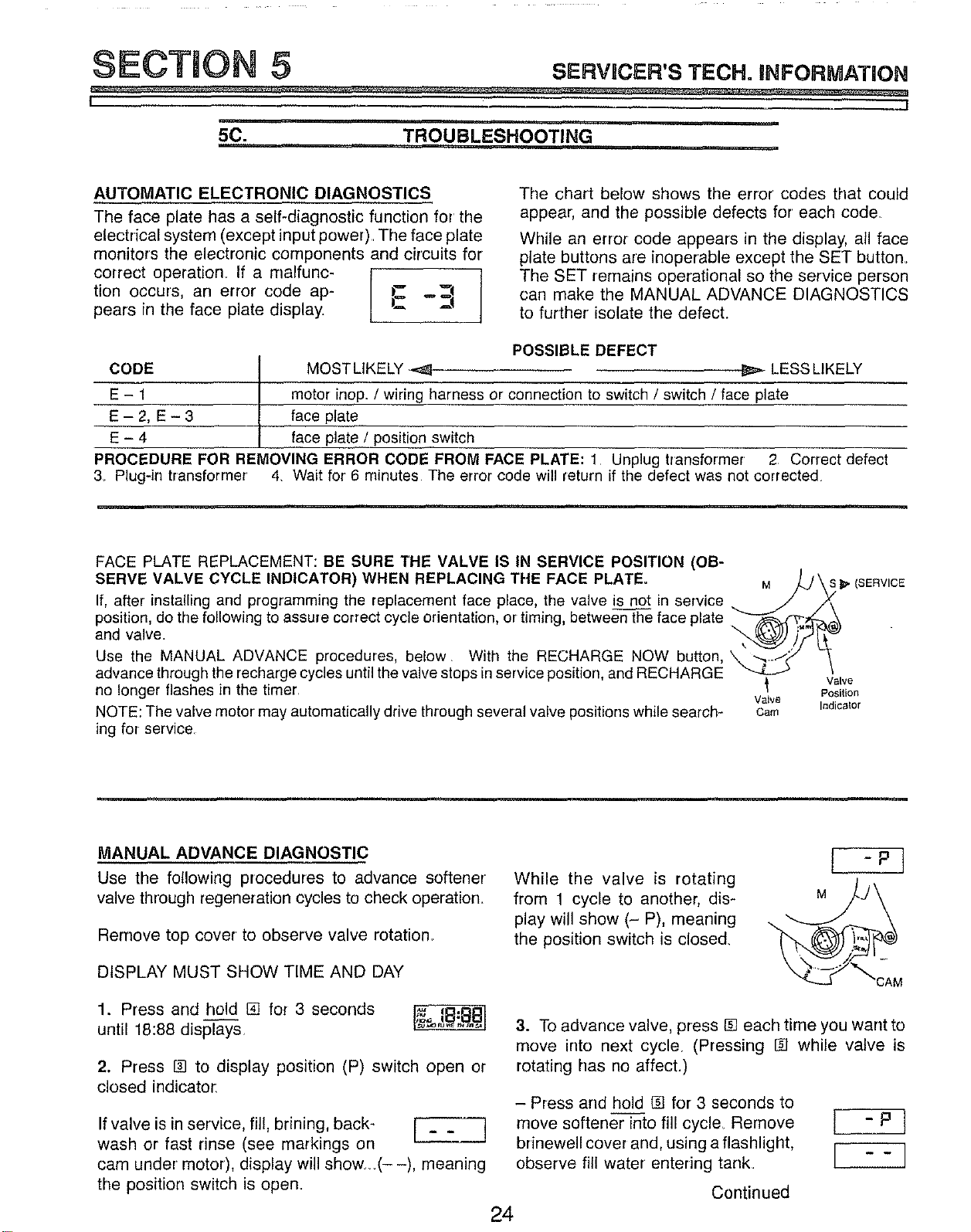
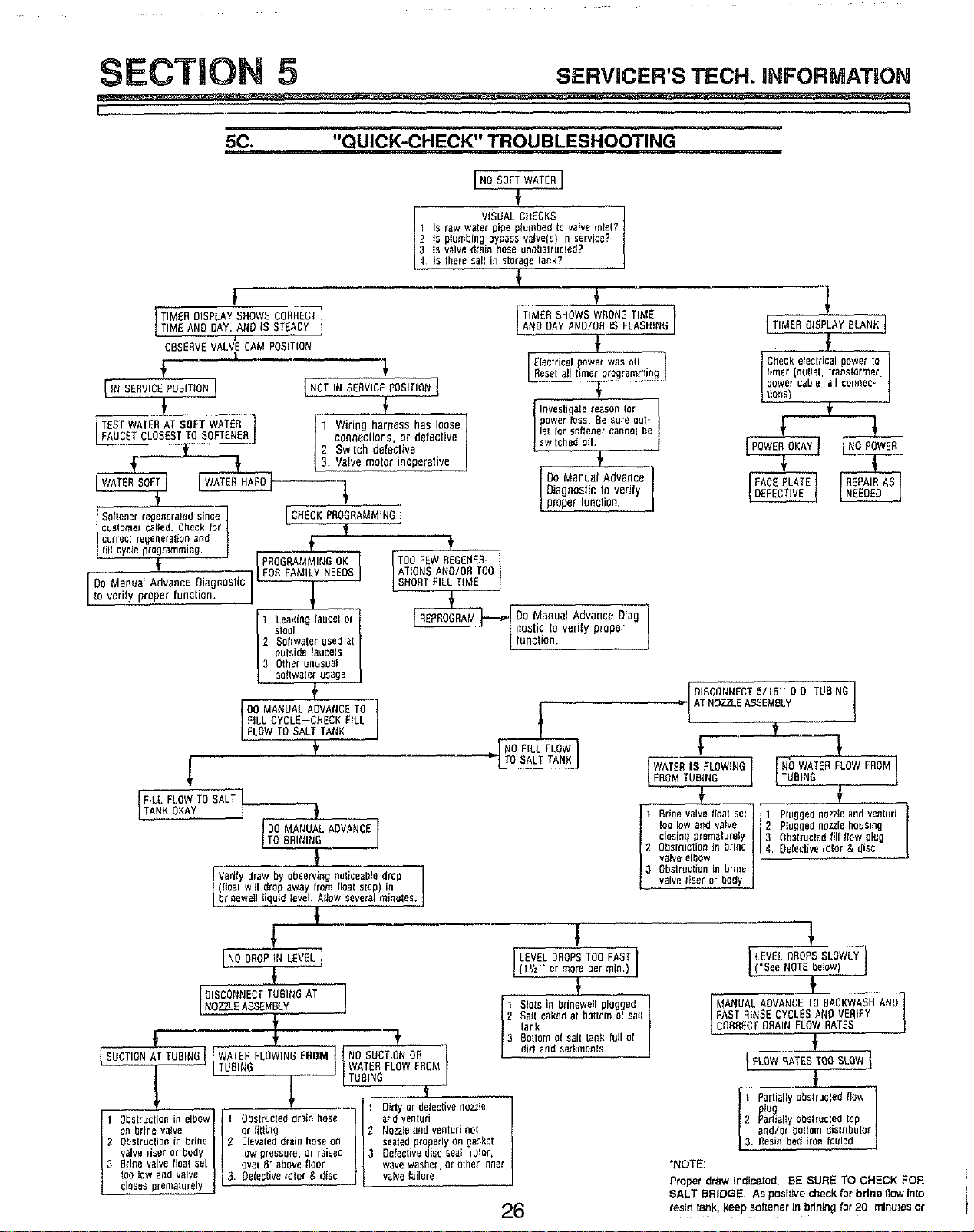
5C. TROUBLESHOOTING
AUTOMATIC ELECTRONIC DIAGNOSTICS
The face plate has a self-diagnostic function for the
electrical system (except input power)The face plate
monitors the electronic components and circuits for
correct operation_ If a malfunc- [ t
tion occurs, an error code ap- E "_
pears in the face plate display.
The chart below shows the error codes that could
appear, and the possible defects for each cede
While an error code appears in the display, all face
plate buttons are inoperable except the SET button.
The SET remains operational so the service person
can make the MANUAL ADVANCE DIAGNOSTICS
to further isolate the defect.
POSSIBLE DEFECT
CODE I MOSTLIKELY -_ _ LESS LIKELY
t
E - 1 I motor inop. / wiring harness or connection to switch / switch / face plate
E - 2, E - 3 face plate
E - 4 face plate / position switch
PROCEDURE FOR REMOVING ERROR CODE FROM FACE PLATE: 1 Unplug transformer' 2 Correct defect
3 Plug-in transformer 4. Wait for 6 minutes The error code will return if the defect was not corrected
FACE PLATE REPLACEMENT: BE SURE THE VALVE IS IN SERVICE POSITION (OB-
SERVE VALVE CYCLE INDICATOR) WHEN REPLACING THE FACE PLATE°
If, after installing and programming the replacement face place, the valve is not in service
position, do the following to assure correct cycle orientation, or timing, between the face plate
and valve.
Use the MANUAL ADVANCE procedures, below. With the RECHARGE NOW button,
advance through the recharge cycles until the valve stops inservice position,and RECHARGE
no longer flashes in the timer
NOTE: The valve motor may automatically drive through several valve positions while search-
ing for service
Valve
Cam
i_"(SERVICE
Valve
Position
Indicator
MANUAL ADVANCE DIAGNOSTIC
Use the following procedures to advance softener
valve through regeneration cycles to check operation,
Remove top cover to observe valve rotation.
DISPLAY MUST SHOW TIME AND DAY
While the valve is rotating
from 1 cycle to another, dis-
play will show (- P), meaning
the position switch is closed,
1. Press and hold [] for 3 seconds
until 18:88 displays,
2. Press [] to display position (P) switch open or
closed indicator.
If valve is in service, fil!, brining, back- [ _ _ ]
wash or fast rinse (see markings on
L
J
cam under motor), display will show._(- -), meaning
the position switch is open.
3. To advance valve, press [] each time you want to
move into next cycle. (Pressing _ while valve is
rotating has no affect.)
- Press and hold [] for 3 seconds to
move softener into fill cycle Remove
brinewell cover and, using a flashlight,
observe fill water entering tank.
24
Continued
[ -P]
[ --I
SECTION 5 sE.vmcER'sTEC..I.FO.MATIO.
L !
, i ii ii
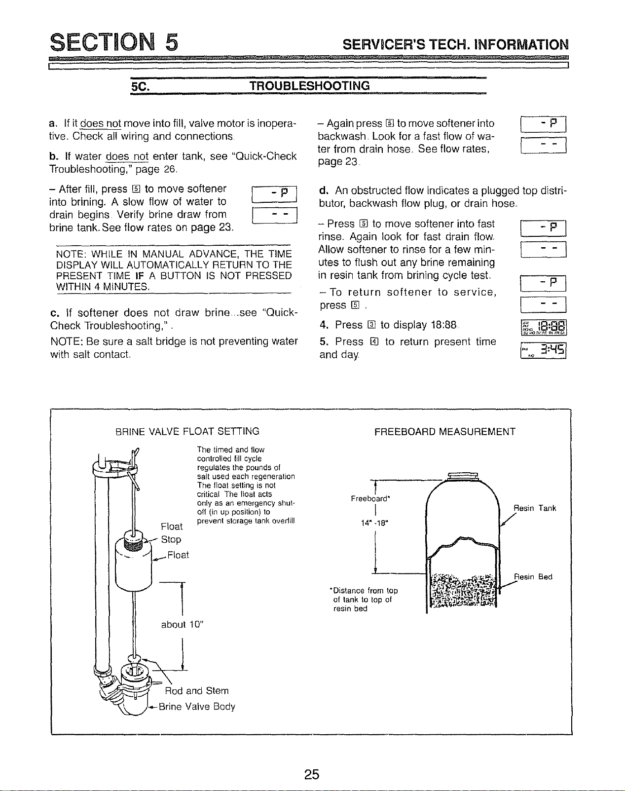
5C. TROUBLESHOOTING
m,i i,i
a, If it does not move into fill, valve motor is inopera-
tive, Check all wiring and connections
b. If water does not enter tank, see "Quick-Check
Troubleshooting," page 26.
- After fill. press [] to move softener l - P }
into brining. A slow flow of water to
drain begins Verify brine draw from
brine tank, See flow rates on page 23.
NOTE: WHILE IN MANUAL ADVANCE, THE TIME
DISPLAY WILL AUTOMATICALLY RETURN TO THE
PRESENT TIME IF A BUTTON IS NOT PRESSED
WITHIN 4 MINUTES.
c. if softener does not draw brine_see "Quick-
Check Troubleshooting,".
NOTE: Be sure a salt bridge is not preventing water
with salt contact.
- Again press [] to move softener into [ - P
backwash Look for a fast flow of wa-
r
ter from drain hose See flow rates, [
i i
page 23
d. An obstructed flow indicates a plugged top distri-
butor, backwash flow plug, or drain hose.
- Press [] to move softener into fast
rinse. Again look for fast drain flOWr
Allow softener to rinse for a few min-
utes to flush out any brine remaining
in resin tank from brining cycle test
-To return softener to service,
press [] .
4. Press I_ to display 18:88
5. Press [] to return present time
and day
[ -P]
[ --I
BRINE VALVE FLOAT SETTING
Float
_Stop
.,,I Float
about 10"
The timed and flow
controlled fill cycle
regulates the pounds of
salt used each regeneration
The float selting is not
critical The float acts
anly as an emergency shut*
aft (in up posilion) to
prevent storage tank ovedill
_( Rod and Stem
J-_-Brine Valve Body
FREEBOARD MEASUREMENT
Freeboard*
!
14" -!8"
"Distance from top
of lank to top of
resin bed
Resin Tank
Resin Bed
25
SECTION 5 s,=.vlcE.'s-r_CH.m.u:o.uA'no.
l_. ,I
H
50. "QUICK-CHECK" TROUBLESH,OO_,!NG ........
T,MflRD,flPLAYSNOWSCOflRECT
IT,MEANDDAY,AND'SSTEADY!
OOflERVEVALV"DAMPOStT'ON
|
ItNflERv,cflPOS,TtDNI _T,NSERV,CROS,T,ON.]
TEST WATER AT SOFT WATER
FAUCET I Wiring harness has looseCLOSESTTO SOFTENER
I connections, or defective
Switch detective
_ . Valve motor inoperative
_o_tleo.g_r_;,_!atc_,do_o_IONECKPRODRRMMINO_]
correcl regeneralion and
,I.
fill cycle p_ogramming. T
[ PROGRAMMINGOK
,)
FOR EAM LY NEEDS
DO Manual Advance Diagnostic ]
o verify proper {unction. | }_
I eaking faucel or
stool
Soflwaler ueed al
outside lauce_s
Other unusua_
soDwa{eru_age
DO MANUAL ADVANCE TO
FILLCYCLE--CHECK FILL
FLOW TO SALT TANK
!
NO SOFT WATER]
I
VtSUAL CHECKS
2 _sp_umbingbypassvalve(s)inservice?
1 Is raw waler pipe plumbed to valve inlel?
3 Is valve drain hose unobslrucled?
4 Is there sall in storage lank?
TIMER SHOWSWRONG TIME
_D DAY ANOIOR IS FLASHING
t
[_,oos,_i_t;,ti'_;,w'_Sro_'_ing]
!
Investigate reason {or |
power toss Be sure out.
J
lel for soflenef cannel be
switched oR
!
Do Manual Advance
Diagnostic to verify
[proper unct on.
f
[TO0 flEW REGENER- I
__ i_T'o°.",V,_b_;°_";DOI
_,[ DO Manual Advance Diag+ ]
I nostic Io verify proper |
[ funelion. J
1 [TIMER DISPLAY BLANK J
1,
Check eteclfical power to
Ilimer(oofle, transformer ]
I D°ne_p°wercableallc°nnec_ /
SALT
[_oos_._,._,u_LADVANCEI
VerUy draw by observing neflceable drop
(Ileal will drop away Nom Ileal slop) in
LbrnewelI qu d love. A ow severN m holes.
-! o,DO,NO!
F
NOWATERFLOW FROM
{ 1{TdOtNOI
Odoeva,vofloa,_e,g_dRluggedno_loaodve°Iod]
too low and valve 2 Plugged nozzlehousing
closing prematurely Obstructed fill flow plug
Obsl_uction in bnne Defective rotor & disc
valve elbow
Obstruclion in brine
valve _iser or body
[NODROPtNLEVEL]
I
DISCONNECT TUBING AT
INO_EASSEMBLY !
SUCTION AT TUBING|lWATER FLOWING PROM l I NO SUCTION OR ]
I ..... I TUBING | I WATER FLOW FROM|
I ' _ _iTUOtNo,
r-- _' _ - I I 1 Dirty or delective nozzle
1 Obstruction in elbow 1 Obstructed drain hose and ventud
I1 onbrinevalve I{1 _r,u; eddrainh°s_ 2 Nozzleandventurino,
I i Obstrucflonin brine fl Elevaled d_ain hose on seated properly on gasket
valve riser or body 3 low pressure, or raised 3 Defective disc seal. roler.
3 Brine valve Ileal set over g' above floor wave washe_ or other inner
closesprematurelyt°°ow and vave 3. _s_sb_du_ii!iiii_c[Defective_oter & disc valve failure
26
1
Slots in bdnewell plugged /
Sad caked at bottomel salt
J
lank
Bottomel salt tank lull o(
dir_ and sediments
"NOTE:
----3
MANUAL ADVANCE TO BACKWASH AND I
FAST RINSE CYCLESAND VERIFY
ICORRECTDRAIN FLOW RATES
l
LELOW.ATE_TOOSLO_',
I
I r Partially obstrucled flow "}
2 PPlaUgallyobslr_cled lop
Propel draw Indicated BE SURE TO CHECK FOR
SALT BRIDGE. AS posl_ve check for brine flow Into
resin tank, _eep softener in bdning for 20 mlnu_ee or
SECTION 5 SERVlCER'STECH. INFORMATION
I I
i ............ ml ,
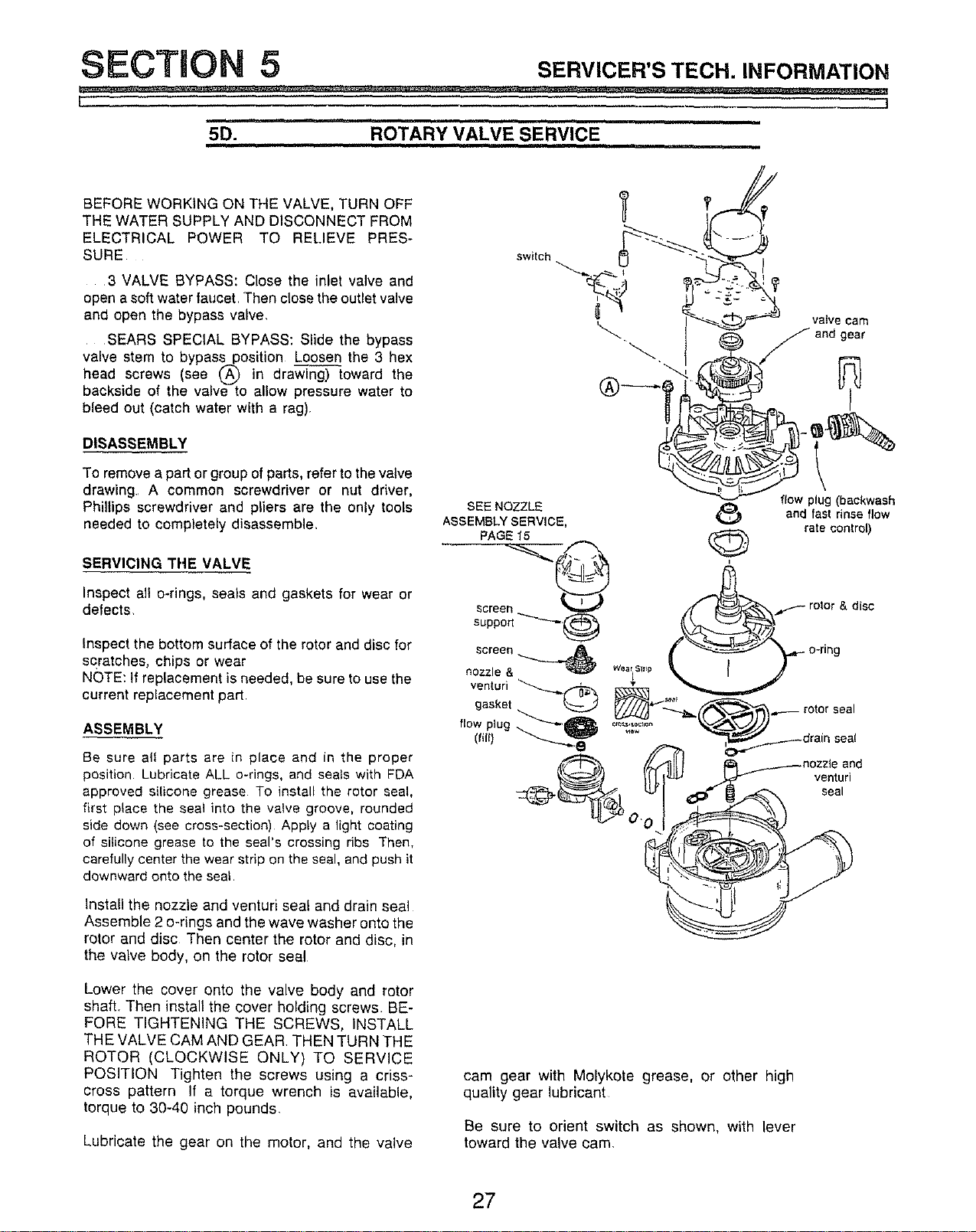
5D. ROTARY VALVE SERVICE
BEFORE WORKING ON THE VALVE, TURN OFF
THE WATER SUPPLY AND DISCONNECT FROM
ELECTRICAL POWER TO RELIEVE PRES-
SURE
3 VALVE BYPASS: Close the inlet valve and
open a soft water faucet, Then close the outlet valve
and open the bypass valve.
SEARS SPECIAL BYPASS: Slide the bypass
valve stem to bypass position Loosen the 3 hex
head screws (see (_ in drawi_oward the
backside of the valve to allow pressure water to
bleed out (catch water with a rag).
DISASSEMBLY
To remove a part or group of parts, refer to the valve
drawing A common screwdriver or nut driver,
Phillips screwdriver and pliers are the only tools
needed to completely disassemble.
SERVICING THE VALVE
Inspect alt o-rings, seals and gaskets for wear or
defects
Inspect the bottom surface of the rotor and disc for
scratches, chips or wear
NOTE: If replacement is needed, be sure to use the
current replacement part.
ASSEMBLY
Be sure aft parts are in place and in the proper
position Lubricate ALL o-rings, and seals with FDA
approved silicone grease To install the rotor seal,
first place the seal into the valve groove, rounded
side down (see cross-section) Apply a light coating
of silicone grease to the seal's crossing ribs Then,
carefully center the wear strip on the seal, and push it
downward onto the seal
Install the nozzle and venturi seal and drain seal
Assemble 2 o-rings and the wave washer onto the
rotor and disc Then center the rotor and disc, in
the valve body, on the rotor seal
Lower the cover onto the valve body and rotor
shaft. Then install the cover holding screws BE-
FORE TIGHTENING THE SCREWS, INSTALL
THE VALVE CAM AND GEAR. THEN TURN THE
ROTOR (CLOCKWISE ONLY) TO SERVICE
POSITION Tighten the screws using a criss-
cross pattern If a torque wrench is available,
torque to 30-40 inch pounds
Lubricate the gear on the motor, and the valve
switch
valve cam
cam gear with Molykote grease, or other high
quality gear lubricant
Be sure to orient switch as shown, with lever
toward the valve cam.
27
SECTION 5 SE.vlcE.'s"rEc.. .r'O.MA'rto.
I ,I
u i
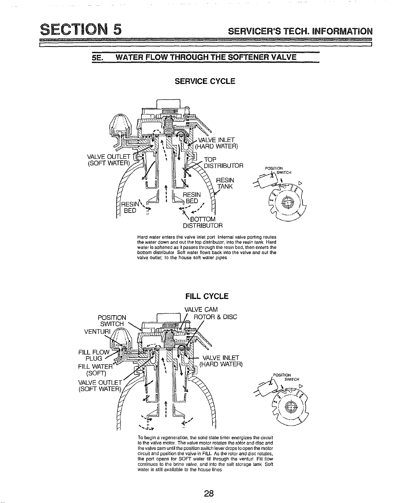
5E, WATER FLOW THROUGH THE SOFTENER VALVE
SERVICE CYCLE
VALVE OUTLET TOP
(SOFT WATER DISTRIBUTOR
POSITION
SWITCH
RESINTANK ._/s_
ILRESIN
B=D, f:'Y I
DISTRIBUTOR
Hard water enters the valve inlet port internal valve porting routes
the water down and out the top distributor, into the resin tank Hard
water is softened as it passes through the resin bed, then enters the
bottom distributor Soft water flows back into the valve and oul the
valve outlet, to the house soft water pipes
FILL CYCLE
FILL FLOW
VALVE CAM
POSITION ROTOR & DISC
SWITCH
VENTURI
FILL
(SOFT)
VALVE OUTLET"
(SOFT WATER
- VALVE INLET
i (HARD WATER)
To begin a regeneration, the solid slate timer energizes Ihe circuit
to the valve motor The valve motor rotates Ihe rotor and disc and
the valve cam untilthe positionswitch lever drops toopen the motor
circuit and positionthe valve in FILL As the roto_and disc rotates,
the port opens for SOFT water fill lhrough the venturi Fill flow
continues to the brine valve, and into the sal storage tank Soft
water is still available to the house lines
28
SECTION 5 SE.vlcE.'s"rEcH.n.FO. ATIO.
I I
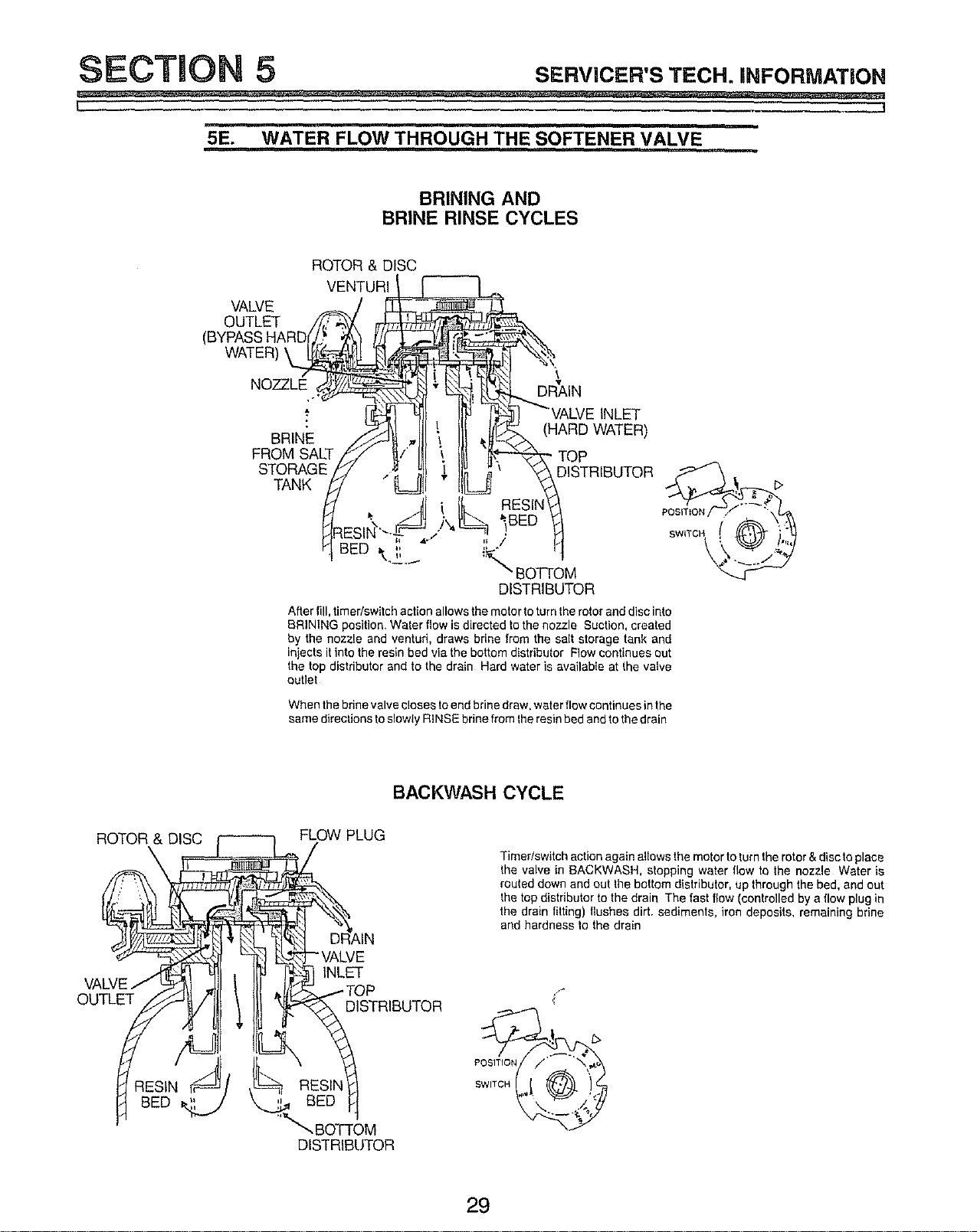
5E. WATER FLOW THROUGH THE SOFTENER VALVE
BRINING AND
BRINE RINSE CYCLES
VALVE
OUTLET
WATER)
ROTOR & DISC
VENTURI
NOZZLE DRVAIN
BRINE
FROM SALT
STORAGE
TANK
INLET
(HARD WATER)
TOP
DISTRIBUTOR
After fill, timer/switch action allows the motor to turn the rotor and disc into
BRINING position, Water fiow is directed to the nozzle Suction, created
by the nozzle and ventud, draws brine from the salt storage tank and
iniects it into the resin bed via the bottom distributor Flow continues out
the top distributor and to the drain Hard water is available at the valve
outlet
When the brine valve closes to end brine draw, water flow continues inthe
same directions to slowly RINSE brine from Ihe resin bed and to the drain
BACKWASH CYCLE
ROTOR & DISC
FLOW PLUG
Timedswitch action again allows the motor to turn the rotor & disc to place
Ihe valve in BACKWASH, stopping water flow to the nozzle Water is
routed down and out the bottom distributor, up through the bed, and out
the top distributor to the drain The fast flow (controlled by a flow plug in
the drain fitting) flushes dirt. sediments, iron deposits, remaining brine
and hardness to the drain
OUTLET
INLET
DISTRIBUTOR
RESIN iriS/ _t RESIN
BED _ _ BED
"_', BOTTOM
DiSTRiBUTOR
29
SECTION 5 sERvucER'sTEC,.I,l=ORM, 'nO.
L !
= , = =
5E. WATER FLOW THROUGH THE SOFTENER VALVE
FAST RINSE CYCLE
ROTOR & DISC
POSITION SWITCH
OUTLET
DRAIN
POSITION
TOP
DISTRIBUTOR _-_-._! b
,k,,_ BOTTOM
DISTRIBUTOR
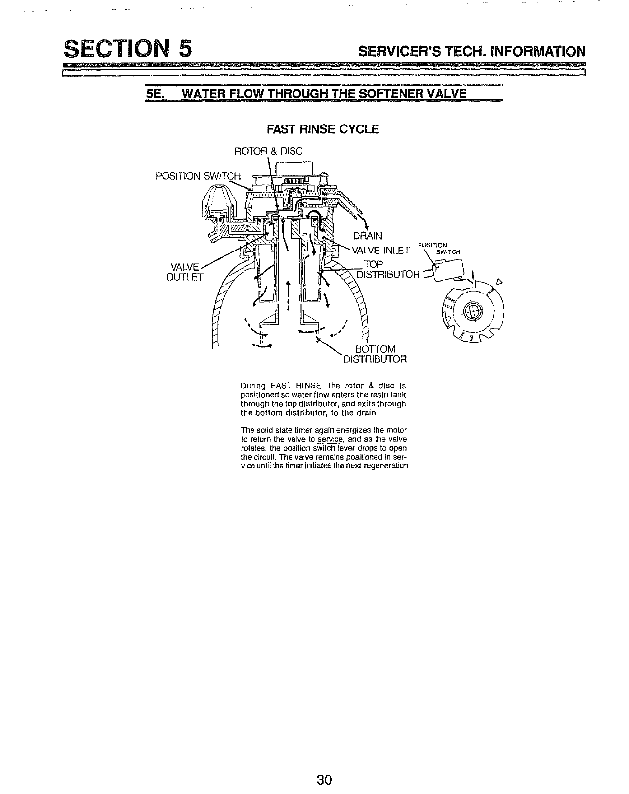
During FAST RINSE, the rotor & disc is
positioned so water flow enters the resin tank
through the top distributor, and exits through
the bottom distributor, to the drain
The solid state timer again energizes the motor
to return the valve to service, and as the valve
rotates, the position switch lever drops to open
the circuit. The valve remains positioned in ser-
vice until the timer initiates the next regeneration
30

L .I
NOTES
31
3
\
VALVE ASSEMBLY
(see page 34)
I
26
25
24
r SOFTENER
ASSEMBLY
2O
17
lO
lJ
16
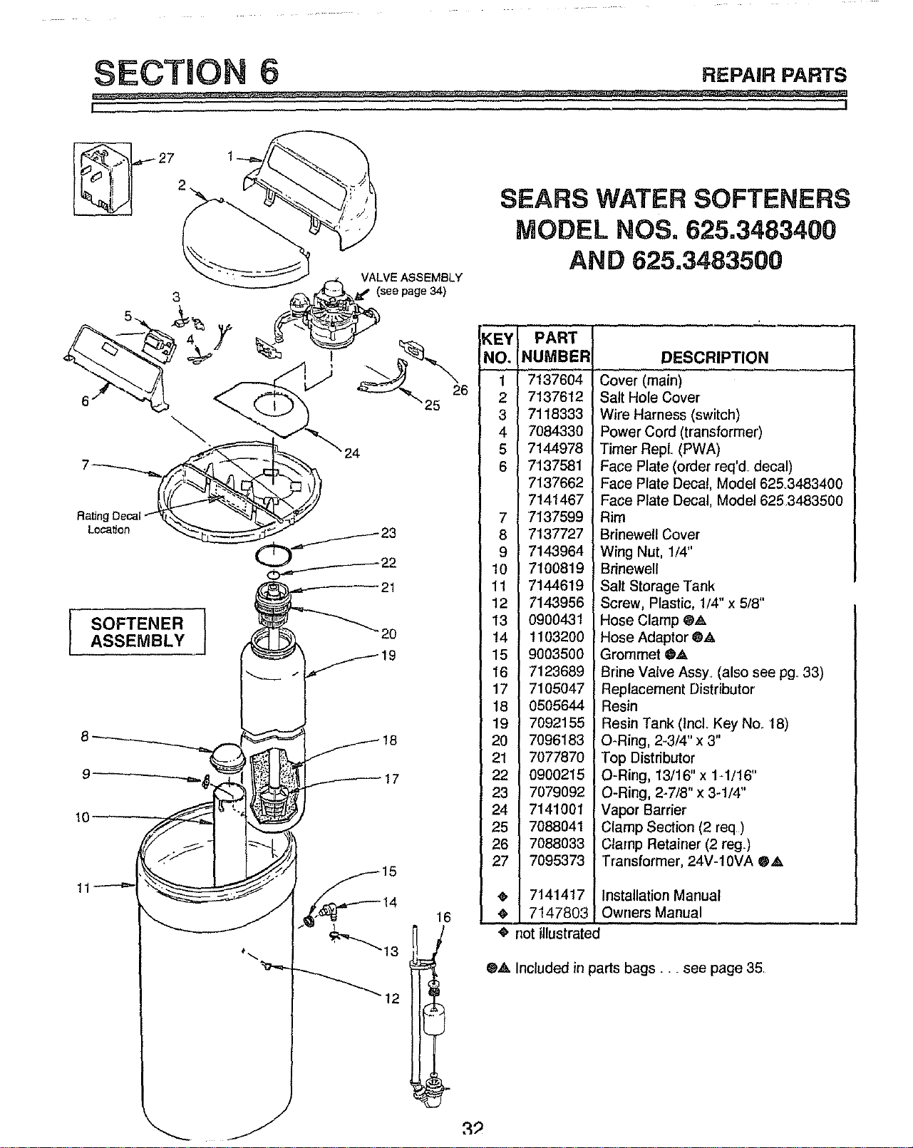
SEARS WATER SOFTENERS
MODEL NOS. 625.3483400
AND 625.3483500
KEY PART
NO. NUMBER
1 7137604
2 7137612
3 7118333
4 7084330
5 7144978
6 7137581
7137662
7141467
7 7137599
8 7137727
9 7143964
10 7100819
11 7144619
12 7143956
13 0900431
14 1103200
15 9003500
16 7123689
17 7105047
18 0505644
19 7092155
20 7096183
21 7077870
22 0900215
23 7079092
24 7141001
25 7088041
26 7088033
27 7095373
7141417
7147803
DESCRIPTION
Cover (main)
Salt Hole Cover
Wire Harness (switch)
Power Cord (transformer)
Timer RepL (PWA)
Face Plate (order req'd decal)
Face Plate Decal, Model 6253483
Face Plate Decal, Model 625.3483
Rim
Brinewell Cover
Wing Nut, 1/4"
Brinewell
Salt Storage Tank
Screw, Plastic, 1/4" x 5/8"
Hose Clamp ®_k
Hose Adaptor @,_
Grommet 0_
Brine Valve Assy, (also see pg 33
Replacement Distributor
Resin
Resin Tank (IncL Key No. 18)
O-Ring, 2-3/4" x 3"
Top Distributor
O-Ring, 13/16" x 1-1/16"
O-Ring, 2-7/8" x 3-1/4"
Vapor Barrier
Clamp Section (2 req)
Clamp Retainer (2 reg)
Transformer, 24V-10VA 0,_,
Installation Manual
Owners Manual
•' not illustrated
®,a, Included in parts bags .... see page 35
SECTION REPAIR PARTS
L I
47_
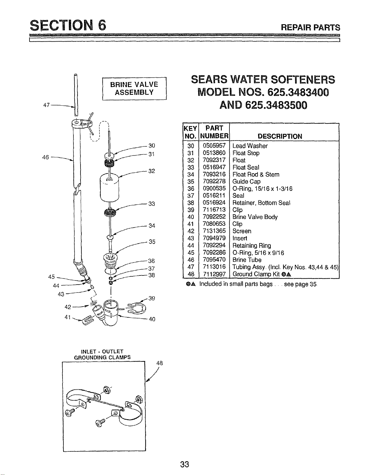
BRINE VALVE 1
ASSEMBLY
SEARS WATER SOFTENERS
MODEL NOSo 625,3483400
AND 625.3483500
46
KEY I PART
NO. !NUMBER
30 0605957
31 0513860
32 7092317
33 0516947
34 7093216
35 7092278
36 0900535
37 0516211
38 0516924
39 7116713
40 7092252
41 7080653
42 7131365
43 7094979
4_ 7092294
7092286
46 7095470
47 7113016
48 7112997
O_, Included in
DESCRIPTION
Lead Washer ........
Float Stop
Float
Float Seal
Float Rod & Stern
Guide Cap
O-Ring, 15/16 x 1-3/16
Seal
Retainer, Bottom Seal
Clip
Brine Valve Body
Clip
Screen
Insert
Retaining Ring
O-Ring, 5/16 x 9/16
Brine Tube
Tubing Assy (Incl. Key Nos. 43,44 & 45
Ground Clamp Kit @&
small parts bags., see page 35
INLET - OUTLET
GROUNDING CLAMPS
33
SECTION REPAIRPARTS
1. I
91
BRINE-77\
TUBING _
\
76
75
58
59
60
67
68
69
70
74
73
72
34
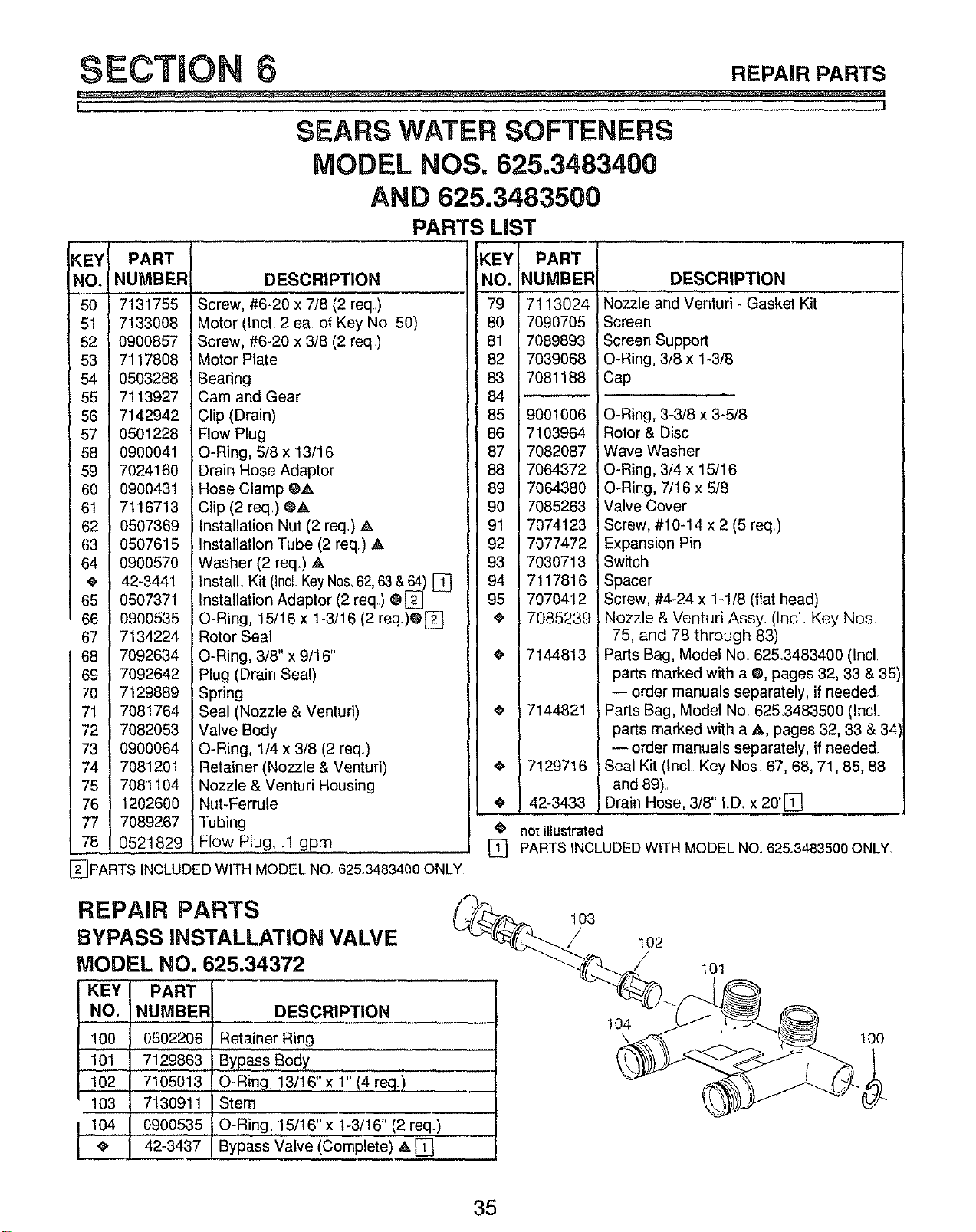
SECTION 6 REPAIRPARTS
k_ t
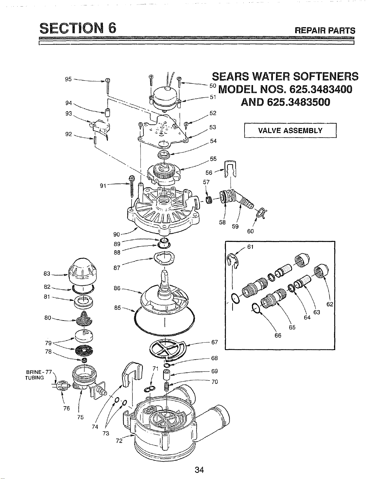
SEARS WATER SOFTENERS
MODEL NOS. 625.3483400
AND 625.3483500
PARTS LIST
KEY
NO.
50
51
52
53
54
55
56
57
58
59
60
6t
62
63
64
65
66
67
68
69
70
71
72
73
74
75
76
77
78
PART i
NUMBERI
7131755
7133008
0900857
7117808
0503288
7113927
7142942
0501228
0900041
7024160
0900431
7116713
0507369
0507615
0900570
42-3441
0507371
0900535
7134224
7092634
7092642
7129889
7081764
7082053
0900064
7081201
7081104
1202600
7089267
0521829
DESCRIPTION
Screw, #6-20 x 7/8 (2 req)
Motor (Incl 2 ea of Key No 50)
Screw, #6-20 x 3/8 (2 req )
Motor Plate
Bearing
Cam and Gear
Clip (Drain)
Flow Plug
O-Ring, 5/8 x 13/16
Drain Hose Adaptor
Hose Clamp CA
Clip (2 req_) Q_k
Installation Nut (2 req) A
Installation Tube (2 req) A
Washer (2 req.) Ak
Install Kit (IncLKeyNos,62,63 &64) []
Installation Adaptor (2 req) @[]
O-Ring, 15/16 x 1-3/16 (2 req.)@[_[]
Rotor Seal
O-Ring, 3/8" x 9/1 6"
Plug (Drain Seal)
Spring
Seal (Nozzle & Venturi)
Valve Body
O-Ring, 1/4 x 3/8 (2 req)
Retainer (Nozzle & Venturi)
Nozzle & Venturi Housing
Nut-Ferrule
Tubing
Flow Plug, .1 gpm
[_PARTS INCLUDED WITH MODELNO. 62&3483400 ONLY
KEY
NO.
79
80
81
82
83
84
85
86
87
88
89
90
[91
92
93
94
95
i*
i
i
i
io
i
i°
PART
NUMBER
7113024
7090705
7089893
7039068
7081188
9001006
7103964
7082087
7064372
7064380
7085263
7074123
7077472
7030713
7117816
7070412
7085239
7144813
7144821
7129716
42-3433
DESCRIPTION
Nozzle and Venturi - Gasket Kit
Screen
Screen Support
O-Ring, 3/8 x 1-3/8
Cap
O-Ring, 3-3/8 x 3-5/8
Rotor & Disc
Wave Washer
O-Ring, 3/4 x 15/16
O-Ring, 7/16 x 5/8
Valve Cover
Screw, #10-14 x 2 (5 req)
Expansion Pin
Switch
Spacer
Screw, #4-24 x 1-1/8 (flat head)
Nozzle & Venturi Assy. (Incl. Key Nos
75, and 78 through 83)
Parts Bag, Model No. 625.3483400 (IncL
parts marked with a O, pages 32, 33 & 3.=
-- order manuals separately, if needed.
Parts Bag, Model No. 625.3483500 (Incl
parts marked with a A, pages 32, 33 & 3,
-- order manuals separately, if neede&
Seal Kit (Incl Key Nos. 67, 68, 71,85, 88
and 89)
Drain Hose, 3/8" I.D. x 20'E]
4_ not illustrated
[] PARTS INCLUDED WITH MODEL NO 62&3483500 ONLY,
REPAIR PARTS
BYPASS INSTALLATION VALVE
MODEL NO. 625.34372
KEY PART
NO. NUMBER DESCRIPTION
100 0502206 Retainer Ring
101 7129863 Bypass Body
102 7105013 O-Ring, 13/16" x 1" 14 req.)
103 7130911 IStem
104 0900535 iO-Ring, 15/16" x 1-3/16" (2 req.)
e. 42-3437 Bypass Valve (Complete) A. []
103
/
104
102
101
too
35
S_FARS
Water Softeners
OWNERS
MANUAL
SERVICE
MODEL NOS.
625.3483400
625.3483500
Your Sears Water Softener has added value when you consider
that Sears has service units nationwide staffed with Sears trained
technicians - professional technicians specifically trained on
Sears products, having the parts, tools and equipment to ensure
that we meet our pledge to you - "We Service What We Sell."
The model number of your water softener is found on the rating
decal. This decal is on the rim, under the salt hole cover°
HOW TO ORDER
REPAIR PARTS
SHOULD A NEED EVER
EXIST FOR REPAIR
SERVICE OR PARTS:
WHEN ORDERING REPAIR PARTS, ALWAYS GIVE THE FOLLOW-,
ING INFORMATION:
-- PART NUMBER
-- MODEL NUMBER
-- PART DESCRIPTION
-- NAME OF ITEM
FOR REPAIR SERVICE, CALL
THIS TOLL FREE NUMBER:
1-800-4-REPAIR
(1-800-473-7247)
FOR REPLACEMENT PARTS
INFORMAl'ION AND
ORDERING, CALL THIS TOLL
FREE NUMBER:
1-800-FON-PART
(1-800-366-7278)
When Sears arranges the installation, you can be sure the job is done
right. We will arrange for professional workmanship.., and we'll take
care of the entire project. What's more, during installation you get in-
sured protection against property damage and also against accidents
to workmen_ All you have to do is talk to your Sears salesperson or
call your nearest Sears store today for detailed information.
Sears, Roebuck and Co., Chicago, III. 60684 U.S.A.
ii i
#7147803 (7/94)