Loading ...
Loading ...
Loading ...
24
Page 22
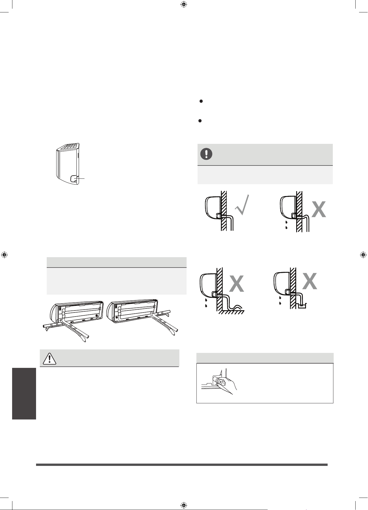
Indoor Unit
Installation
Step 4: Prepare refrigerant piping
The refrigerant piping is inside an insulating
sleeve attached to the back of the unit. You
must prepare the piping before passing it
through the hole in the wall.
1. Based on the position of the wall hole relative
to the mounting plate, choose the side from
which the piping will exit the unit.
2. If the wall hole is behind the unit, keep the
knock-out panel in place. If the wall hole is to
the side of the indoor unit, remove the plastic
knock-out panel from that side of the unit.
3.
If existing connective piping is already
embedded in the wall, proceed directly to
the Connect Drain Hose step. If there is no
embedded piping, connect the indoor unit’s
refrigerant piping to the connective piping
that will join the indoor and outdoor units.
Refer to the Refrigerant Piping Connection
section of this manual for detailed instructions.
NOTE ON PIPING ANGLE
Refrigerant piping can exit the indoor unit from
four different angles:Left-hand side,Right-hand
side, Left rear, Right rear.
Knock-out Panel
CAUTION
Be extremely careful not to dent or damage
the piping while bending them away from
the unit. Any dents in the piping will affect
the unit’s performance.
Step 5:
Connect drain hose
By default, the drain hose is attached to the left-
hand side of unit (when you’re facing the back
of the unit). However, it can also be attached to
the right-hand side. To ensure proper drainage,
attach the drain hose on the same side that your
refrigerant piping exits the unit.
Wrap the connection point firmly with Teflon
tape to ensure a good seal and to prevent leaks.
Remove the air filter and pour a small amount
of water into the drain pan to make sure that
water flows from the unit smoothly.
NOTE ON DRAIN HOSE
PLACEMENT
Make sure to arrange the drain hose
according to the following figures.
.
PLUG THE UNUSED DRAIN HOLE
To prevent unwanted leaks
you must plug the unused
drain hole with the rubber
plug provided.
CORRECT
Make sure there are no kinks
or dent in drain hose to ensure
proper drainage.
NOT CORRECT
Kinks in the drain hose
will create water traps.
NOT CORRECT
Do not place the end of the
drain hose in water or in
containers that collect water.
This will prevent proper
drainage.
NOT CORRECT
Kinks in the drain hose
will create water traps.
Page 23
Indoor Unit
Installation
BEFORE PERFORMING ANY
ELECTRICAL WORK, READ THESE
REGULATIONS
1. All wiring must comply with local and national
electrical codes, regulations and must be
installed by a licensed electrician.
2. All electrical connections must be made
according to the Electrical Connection Diagram
located on the panels of the indoor and outdoor
units.
3. If there is a serious safety issue with the power
supply, stop work immediately. Explain your
reasoning to the client, and refuse to install the
unit until the safety issue is properly resolved.
4. Power voltage should be within 90-110% of
rated voltage. Insufficient power supply can
cause malfunction, electrical shock, or fire.
5. If connecting power to fixed wiring, install a
surge protector and main power switch with
a capacity of 1.5 times the maximum current
of the unit.
6. If connecting power to fixed wiring, a switch
or circuit breaker that disconnects all poles and
has a contact separation of at least 1/8in (3mm)
must be incorporated in the fixed wiring. The
qualified technician must use an approved
circuit breaker or switch.
7. Only connect the unit to an individual branch
circuit outlet. Do not connect another
appliance to that outlet.
8. Make sure to properly ground the air conditioner.
9. Every wire must be firmly connected. Loose
wiring can cause the terminal to overheat,
resulting in product malfunction and possible fire.
Do not let wires touch or rest against refrigerant
tubing, the compressor, or any moving parts
within the unit.
If the unit has an auxiliary electric heater, it must
be installed at least 1 meter (40in) away from
any combustible materials.
To avoid getting an electric shock, never touch
the electrical components soon after the power
supply has been turned off. After turning off
the power, always wait 10 minutes or more
before you touch the electrical components.
WARNING
BEFORE PERFORMING ANY ELECTRICAL
OR WIRING WORK, TURN OFF THE
MAIN POWER TO THE SYSTEM.
Step 6: Connect signal cable
The signal cable enables communication between
the indoor and outdoor units. You must first
choose the right cable size before preparing it for
connection.
Cable Types
•
Indoor Power Cable
(if applicable):
H05VV-F or H05V2V2-F
•
Outdoor Power Cable:
H07RN-F
•
Signal Cable: H07RN-F
Minimum Cross-Sectional Area of
Power and Signal Cables (For reference)
10.
11.
12.
Rated Current of
Appliance (A)
Nominal Cross-Sectional
Area (mm²)
> 3 and ≤ 6
0.75
> 6 and ≤ 10
1
> 10 and ≤ 16
1.5
> 16 and ≤ 25
2.5
> 25 and ≤ 32
4
> 32 and ≤ 40
6
CHOOSE THE RIGHT CABLE SIZE
The size of the power supply cable, signal
cable, fuse, and switch needed is determined
by the maximum current of the unit. The
maximum current is indicated on the nameplate
located on the side panel of the unit. Refer to
this nameplate to choose the right cable, fuse,
or switch.
Loading ...
Loading ...
Loading ...