Loading ...
Loading ...
Loading ...
E5
Surface Installation Flush Mount Installation
8
DUCT RECESS
BOTTOM
DUCT
ASSEMBLY
FOOT
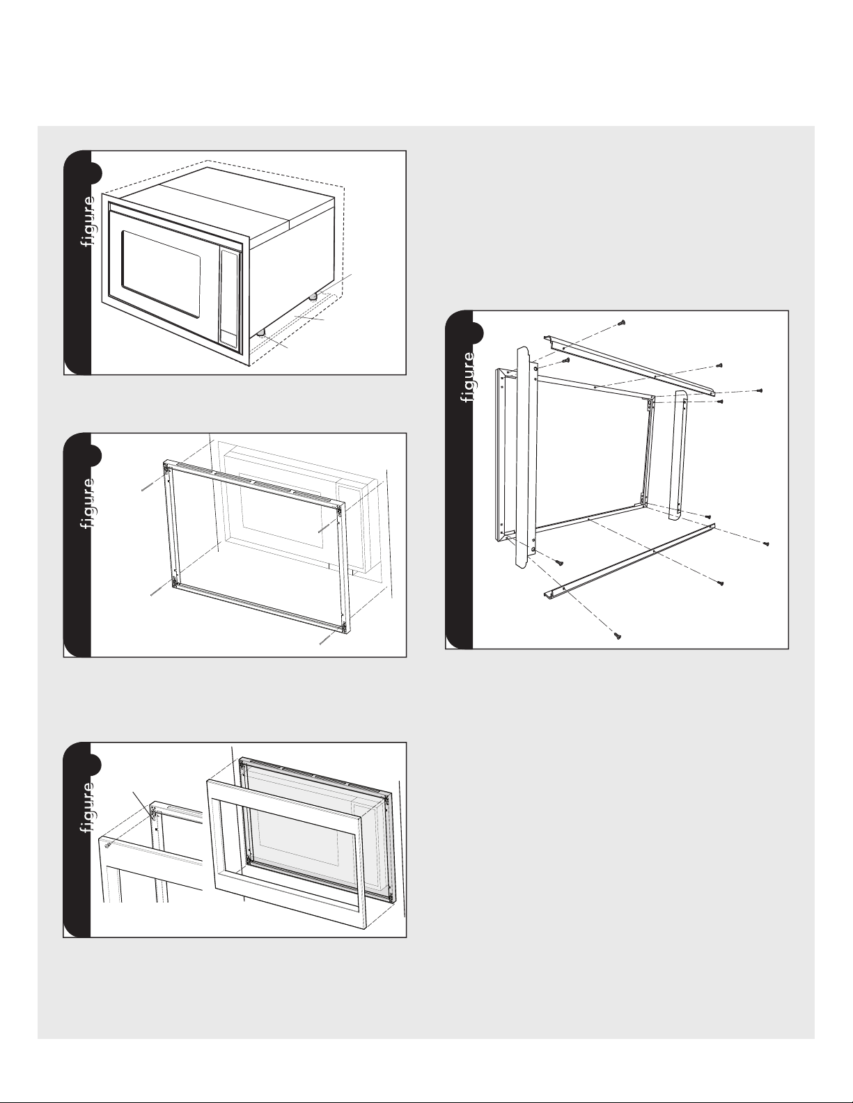
CABINET INSTALLATION: Avoid pinching the cord between the oven
and the wall. Adjust the position of the oven so that the feet of the oven
are fitted into the holes of the Bottom Duct Assembly. See figure 8.
9
SCREW (B)
SCREW (B)
SCREW (B)
SCREW (B)
FRAME INSTALLATION: Position the BACK FRAME to align with the
predrilled holes that were drilled with the mounting template. Check
that it is level and then secure with four SCREWS (B). See figure 9.
Secure the bottom portion of the BACK FRAME with the two remaining
SCREWS (B).
!
SNAP
ATTACHMENT
DECORATION INSTALLATION: Place the FRONT decoration onto the
FRAME and align ball studs and receivers. Secure the DECORATION
to the FRAME by firmly pushing the front frame onto the back frame
engaging the four (4) snap attachments. See figure !.
PARTS INCLUDED IN FLUSH MOUNT ACCESSORY KIT
(PURCHASED SEPARATELY):
•(2) Stainless Steel Scoops
•(10) Stainless Machine Screws
•(1) Flush Mount Template
•(2) Side Trim
* See FLUSH MOUNT TEMPLATE for additional installation instructions.
"
FLUSH MOUNT INSTALLATION: Place the 2 Scoops on the back of
the frame as shown and align the screw holes on the scoop with the
tapped holes in the frame. Secure the scoops to the frame using 6
of the machine screws provided in the kit. Place the side trim pieces
on the back of the frame as shown and align the top and bottom
most screw holes with the corresponding taped holes in the frame.
Secure the trim pieces with the 4 remaining machine screws provided.
Attach the frame assembly to the wooden side spacers by aligning
the mounting holes in the frame with the pre-drilled holes in the side
spacers and secure with SCREW (B) provided with the trim kit. See
figure ".
DECORATION INSTALLATION: Place the FRONT decoration onto the
FRAME and align ball studs and receivers. Secure the DECORATION
to the FRAME by firmly pushing the front frame onto the back frame
engaging the four (4) snap attachments. See figure !.
Loading ...
Loading ...
Loading ...