Owner's
Manual
Model No.
139.53335SRT3
139.53645SRT3
139.53646SRT2
139.53648SRT2
139.53650SRT
139.53660SRT1
139.53834SRT3
For Residential Use
Only
Caution:
Read and follow all
safety rules and
operating instructions
before first use of this
product.
Fasten the manual
near the garage door
after installation.
Complies with UL 325
regulations effective
January 1, 1993
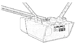
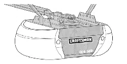
o o o o_'_' "" ...._=_:_'
CRRFTSHRN®
GARAGE DOOR OPENER
• Safety Precautions
• Assembly
• Installation
• Adjustment
• Care and Maintenar_c_-
• Operation
• Troubleshooting
• Parts List
Sears, Roebuck and Co., Hoffman Estates, IL 60179 U.S.A.
Contents Page
A reviewofsafetyalert symbols.................................2
You'llneedtools..........................................................3
Safety informationregardinggaragedoorlocks
and ropes..................................................................3
Testingyourgarage doorforstiddng,binding
end balance...............................................................3
IllustraUonofsectionaldoorinstallation.....................4
Illustrationofone-piecedoorinstailalJon...................5
Cartoninventory..........................................................6
Hardwareinventory.....................................................7
Assembly seotlon - pages 8- 11
AssembleT-rail.........................................................8
Attachcablepulleybracket.......................................8
Installtrolley..............................................................9
FastenT-railtoopener .............................................9
Installchain/cable...................................................10
Attachsprocketcover.............................................10
Tightenthechainand cable...................................11
Installation section - pages 11 - 27
Installationsafetyinstructions.................................11
Determineheaderbracketlocation
Sectionaldoor.......................................................12
One-piecedoor.....................................................13
Installthe headerbracket.......................................14
AttachtheT-reil toheaderbracket.........................15
Positionthe opener.................................................16
Hangthe opener.....................................................17
Installthe doorcontrol............................................18
Contents Page
Installthelight and lens.................................................19
Attachemergency release rope and handle.................19
Bectricalrequirememts.................................................20
Safety reversingsensorinformation..............................21
Installthesafety reversingsensor...........................22, 23
Fastendoorbracket(sectionaldoor)............................24
Fastendoorbracket(one-piecedoor)...........................25
Connectdoorarmtotrolley(sectionaldoor).................26
Connectdoorarmtotrolley (one-piecadoor)...............27
Adjustment section - pages 28 - 30
Travellimitadjustments.................................................28
Forceadjustments.........................................................29
Testthe safety reversingsensor...................................30
Testthesafetyreversesystem ....................................30
Operationsafety instructions...........................................31
Care ofyouropener.........................................................31
Maintenanceschedule....................................................31
Opera,onofyouropener................................................32
Receiverandremotecontrol programming....................33
Havinga problem?....................................................34, 35
Repairparts,railassembly..............................................36
Repairparts, installation..................................................36
Repairparts,openerassembly.......................................37
Accassodes......................................................................38
Index................................................................................39
How toorder repairpads.................................................40
Maintenanceagreement..................................................40
Warranty..........................................................................40
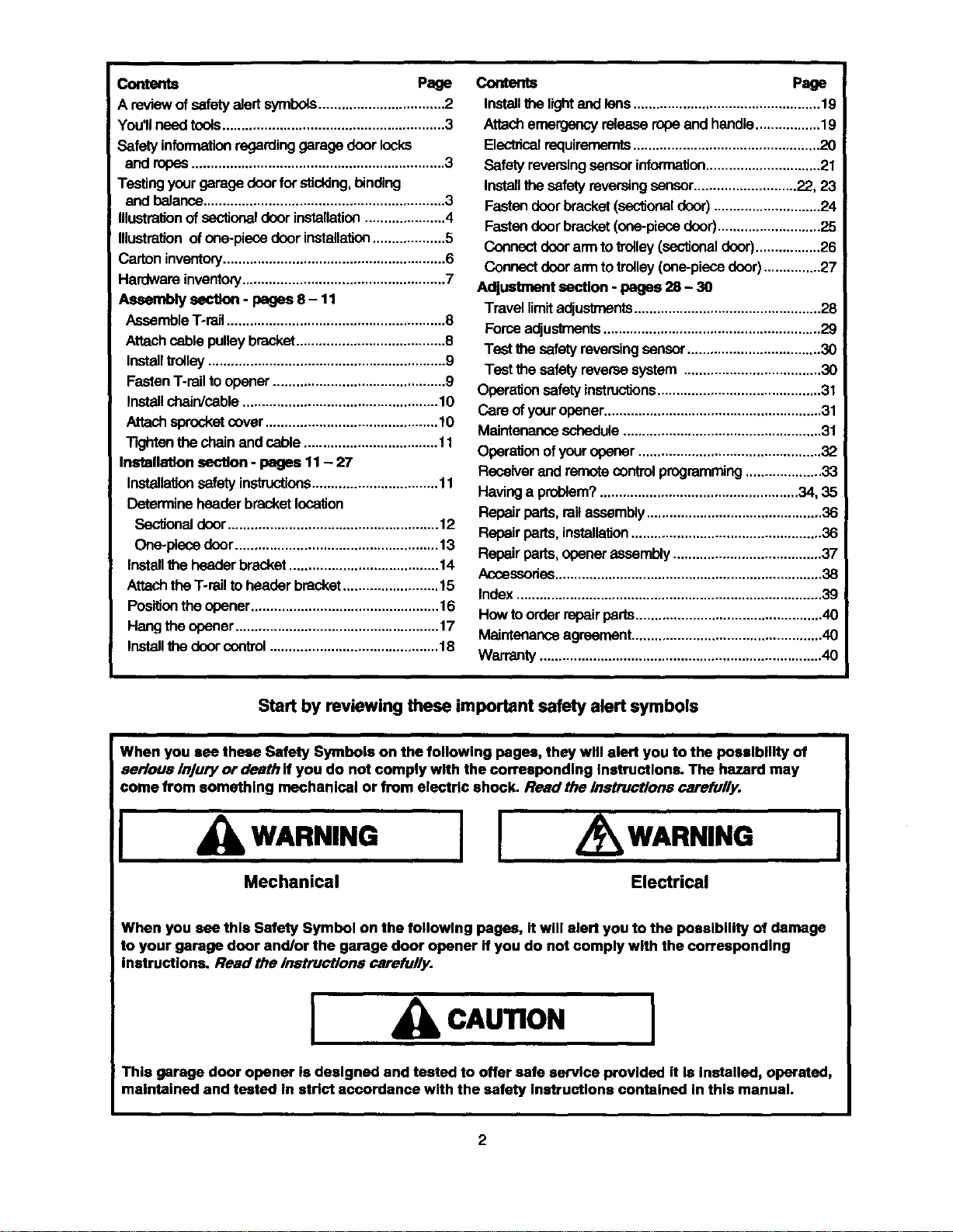
Start by reviewing these important safety alert symbols
When you see these Safety Symbols on the following pages, they will alert you to the possibility of
serious Injury ordeath ff you do not comply with the corresponding Instructions. The hazard may
come from something mechanical or from electric shock. Read the instructions carefully.
I
WARNING
I
I
WARNING
Mechanical Electrical
When you see thle Safety Symbol on the following pages, It will alert you to the possibility of damage
to your garage door and/or the garage door opener If you do not comply with the corresponding
instructions. Read the inatruct/on$ carefully.
I
CAUTION
I
This garage door opener Is designed and tested to offer safe service provided it Is Installed, operated,
maintained and tested In strict accordance with the safety Instructions contained In this manual.
2
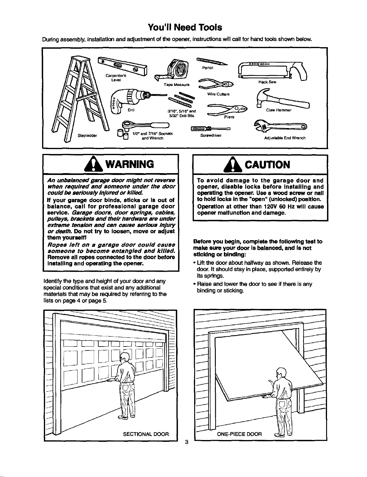
You'll Need Tools
Duringassembly,installationand adjustmentof the opener,instructionswillcall for handtoolsshown below.
Stepladder
Level
HaCk Saw
Tape Measure
Screwdriver Adjustable End Wrench
WARNING
An unbalanced garage door might not reverse
when required and someone under the door
could be seriously injured or k//l_.
If your garage door binds, sticks or Is out of
balance, call for professional garage door
service. Gsrsge doors, door springs, cables,
pulleys, brackets and their hardware are under
extreme tension and can cause serious injury
or death. Do not try to loosen, move or adjust
them yourself!
Ropes left on a garage door could cause
someone to become entangled and killed.
Remove all ropes connected to the door before
installing and operating the opener.
Identifythe typeand height ofyourdoorand any
specialconditionsthat existand any additional
materialsthat may be requiredby referringtothe
listson page 4 or page 5.
CAUTION
To avoid damage to the garage door and
opener, disable locks before Installing and
operating the opener. Use e wood screw or nail
to hold locks In the "open" (unlocked) position.
Operetlon at other than 120V 60 Hz will cause
opener malfunction and damage.
Before you begin, complete the following test to
make sure your door Is balanced, and Is not
stlcldng or binding:
• Liftthe door abouthalfway as shown. Release the
door.It should stay in place, supportedentirelyby
itssprings.
• Raise and lowerthe doorto see ifthere isany
bindingor sticking.

SECTIONAL Door Installation I
Before you begin, survey your garage area to
see whether any of the conditions below apply
to your Installation.
Horizontal and vert_al reirdorcernerd
is needed k)r lightweight garage doors
(fibe_gJass,steel, aluminum, door withglass panels, etc.).
See page 24 fordetails.
Slack in Chain Tension
is Normal Wllen
Garage Door is Clos_
FINISHED CEIUNG
Support bracket &
Extension Spring
Fio<xmust be leVel
aches wkJIhof dOOr
Safety Reversing Sensor
Basedon yourparticularrequirements,there are
severalinstallationstepswhichmightcellfor
materials and/orhardwarenotincludedin thecarton.
• Step 1, page 12 - Lookat thewall or ceilingabove
the garage door.The headerbracket mustbe
securelyfastened to structuralsupports.
• Step 5, page 17 - Do you have a finishedceilingin
your garage? If so, a supportbracket and
additionalfasteninghardware may be required.
• Safety reversingsensor,page 21 - Depending
upon garage construction,wood blocksmay need
to be fastenedto mountinglocationsbefore
sensorsare installed.
• Step 10, page 22 - Alternate floormountingof the
safety reversingsensorwillrequire hardwarenot
provided.
• Step 11, page 24 - Do you have a steel, aluminum,
fiberglass or glasspanel door?.Ifso, horizontal
and verticalreinforcementisrequired.
• Lookat the garagedoor where itmeets the floor.
It must close on the floor all the way across.
Other-wise, the safety reverse system may not
work properly. See page 30. Flooror door should
be repaired.
F 8dsr
/all
_r
Closed PosItion
4ead Cabk) Pulley
s_ Bracket
]racket Trolley Rail Assembly
Release
Rope & Handle
Arm
Curved
Arm
• The openercan be installedwithin2 feet of theleft
or rightofthe doorcenter ifthere isa torsionspring
or center bearing plate in the way of the header
bracket or door bracketarea. If your donrhas
extension sp/Yngs,the openermustbe installed
in thecenter ofthe door.See pages 12 and 24.
• Do you have an access door in additionto the
garage door?If not,Model 53702 Emergency
Key Release is required.See page 38.
• Ifyourdoor ismore than 7 feet high,see the longer
railsavailable on page 38.
You may find it helpful to refer back to this page as you proceed with the Installation of your opener.
4
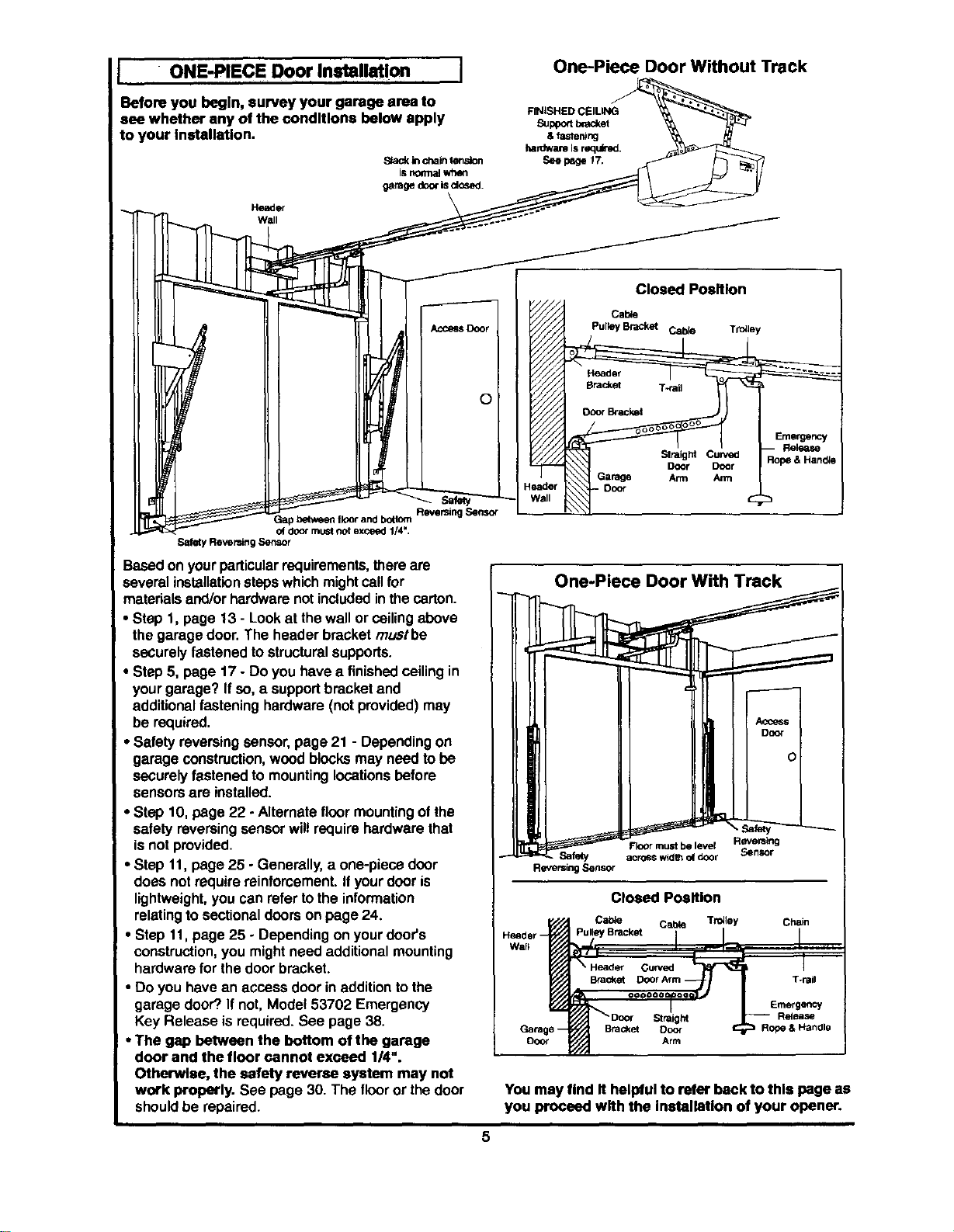
• ONE-PIECE Door Installation I
Before you begin, survey your garage area to
see whether any of the conditions below apply
to your Installation.
S/ack in chain lensJon
isno_malwhen
garage door Is dosed.
Header
Wall
One-Piece Door Without Track
O
ReversingSensor
oi door must not exceed I14*,
Safety Reve_ng Sensor
Basedon yourparticularrequirements,thereare
several installation stepswhichmight cell for
materialsarxJ/orhardwarenotincludedinthe carton.
• Step 1, page 13 - Lookat the wall or ceilingabove
the garagedoor.The headerbracket mustbe
securelyfastened tostructuralsupports.
• Step 5, page 17 - Do you have a finishedceilingin
yourgarage? Ifso, a supportbracket and
additionalfasteninghardware (not provided)may
be required.
• Safety reversingsensor,page 21 - Dependingon
garage construction,wood blocksmay need tobe
securelyfastened to mountinglocationsbefore
sensorsare installed.
• Step 10, page 22 - Alternate floormountingof the
safety reversingsensorwill require hardwarethat
isnot provided.
• Step 11, page 25 - Generally,a one-piece door
does not requirereinforcement.If yourdooris
lightweight,you can refer tothe information
relatingto sectionaldoorson page 24.
• Step 11,page 25 - Dependingon yourdoor's
construction,you mightneed additionalmounting
hardware for thedoor bracket.
• Do you have an access door in additionto the
garage door?If not, Model 53702 Emergency
Key Release is required.See page 38.
•The gap between the bottom of the garage
door and the floor cannot exceed 1/4".
Otherwise, the safety reverse system may not
work properly. See page 30. The flooror thedoor
shouldbe repaired.
Closed Poaltlon
Cable
Pulk_yBracket Cabk_ Trniley
SlraigM Curve_
Door Door
Arm Arm
E_ader Door
Nail
One-Piece Door With Track
Reversing
FloOrmust be level
Safety across w:dlh o(door
Reversing Sensor
Closed Position
Cable Cabte TroJley Chain
Bracket
Ooor
Straight
Bracket Ooor Rope & Handle
Arm
You may find It helpful to refer beck to this page as
you proceed with the Inatallatlon of your opener.
5
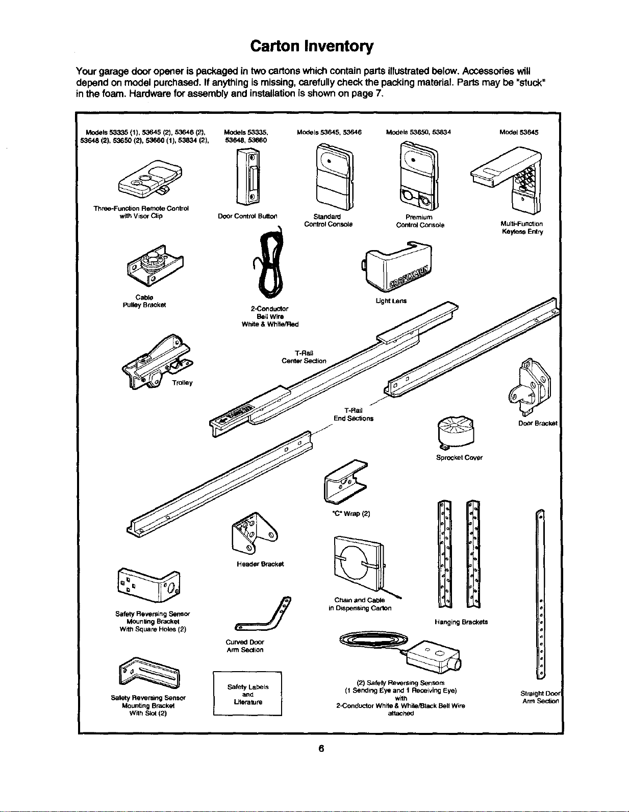
Carton Inventory
Yourgarage door opener is packagedin two cartonswhichcontainparts illustratedbelow. Accessorieswill
depend on modelpurchased. If anythingismissing,carefullycheckthe packingmaterial. Partsmay be "stuck"
in the foam. Hardware for assembly and installationisshownon page 7.
Models 53335 (1), 53645 (2), 53646 (2),
53648 (2), 53650 (2), 53660 (1), 53834 (2),
Tbree-Funotion RemOte Control
with VisorClip
Cable
Pulley Bracket
Models 53335, MOdels53645, 53646 Models 53650, 53834 Model 53645
53648, 53660
Door Control Buito_l Standard Premium
Control Console Control Console Muiti-Function
2-Conduotor
Bellwire
White & White/Fled
Light Lens
_ Door Bracket
T-Rail
Center SeOtion
T-Rail
End S_clJon_
•c"Wrap(2)
Header Bracket
J Chain and Cable
Safety Reversing Sensor in Dispensing Carton
Mounting Bracket
With Square Holes (2)
Curved Door
Arm Seolion
Safety Labels
and
Literature
Sprocket Cover
Hanging Brackets
(2) Safely Reversing Sensors
(1 Sanding Eye and 1 Receiving Eye)
',Vith
2-Conduotor White & White/Black Sail Wire
Safety Reversing Sensor
Mounting Bracket
With S_4 (2)
attached
Straight Doo
Arm Section
6
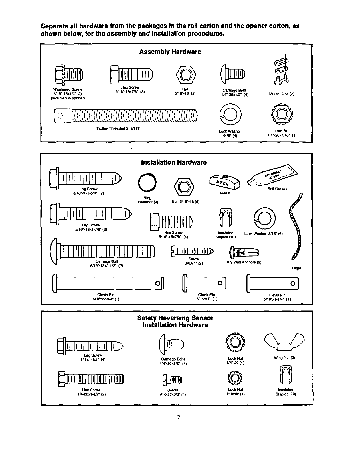
Separate all hardware from the packages in the rail carton and the opener carton, as
shown below, for the assembly and installation procedures.
Assembly Hardware
Washered Screw Hex Screw Nut
5/16" 18xl/2" (2) 5/16"-18x7/8" (3) 5/16'-18 (5)
(mounted in opener)
Trolley Threa(_ed Shaft (1)
Carriage Bolts
1/4"-20xl/2" (4) Master Link (2)
© @
LockWasher Lock Nut
5/16' (4) 1/4" 2Ox7/16" (4)
Installation Hardware
[ llllllllllll C)
5/16"L_'ggX1Scr-5/_(2) Handle
Ring
Fa_ener (3) Nut 5/16°-18 (6)
Illllllllllllllllllll[__0so-_
5/16"-18xl-7/8" (2)
Hex Screw Insulated
5/16"-18x7/8" (4) StepPes(10)
011111flJllllJflllllllllJlllllllllllD_1ii _>
Screw
Carriage I_t 6ABxl" (2)
5/16"-18x2-1/2" (2)
Rail Grease
©
Lock Washer 5/16" (6)
DPi W_dlAr_hors (2)
I
Rope
Clevis Pin Clevis Pin
5/16"x2-3/4" (1) 5/16"x1" (1)
Clevis Pin
5/16"x1-1/4" (1)
Safety Reversing Sensor
Installation Hardware
1/4 x1-1/2" (4) Carriage Bolts Lock Nut
1/4"-20x1_2" (4) 1/4'-20 (4)
Hex Screw Screw Lock Nut
1/4-20x1-1/2" (2) #10-32x5/8" 141 #10x32 (4)
Wing Nut (2)
Insulated
Staples (20)
Assembly Section: Pages 8 - 11
To avoid installation difficulties, do not run the garage door opener until instructed to do so.
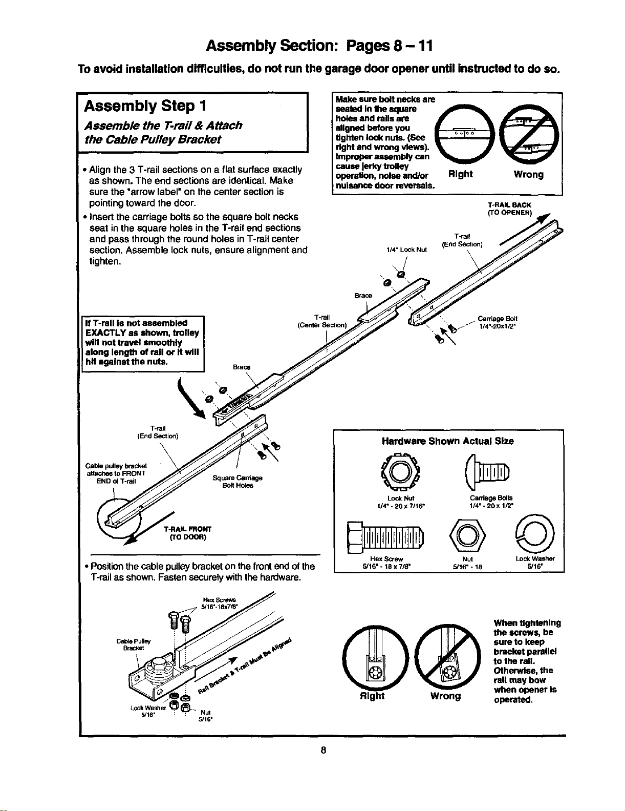
Assembly Step I
Assemble the T-rail & Attach
the Cable Pulley Bracket
• Alignthe 3 T-rail sectionson a flatsurface exactly
as shown. The end sectionsare identical.Make
sure the "arrowlabel=on thecentersectionis
pointingtowardthedoor.
• Insertthe carriage boltssothe square boltnecks
seat in thesquare holes inthe T-rail end sections
and passthroughthe roundholesin T-rail center
section.Assemble lock nuts,ensure alignmentand
tighten,
Makesureboltnecksare
inthe square
holesandrails are
alignedbeforeyou
tighten locknuts.(See
rightand wrongviews). _ J
Improperassemblycan
cause Jerkytrolley
opera.n, noiseand/or Right
nulsencedoorreversals.
T-rail
1/4" LOCkNut (End Section)
\
Wrong
T-RAIL BACK
(TO OPENER)
O
Brace
IfT-ragIsnotassembled I
EXACTLYas shown,trolley I
willnottravel smoothly
along length of railor Itwill
hit againstthe nuts. I
T-rail
(CenterSection]
-, Carriage Bclt
, _ 1/4"-20xl/2"
T-rail
(End Section)
Cable pulley bracket
aUa¢_4_ to FRONT
END of T-rail Square Carnage
Bolt Hctss
T-RAIL FRONT
(TODOOR)
• Positionthecable pulleybracketon thefrontend ofthe
T-railas shown.Fastensecurelywiththehardware.
Hardware Shown Actual Size
©
LockNut
1/4"- 20 x 7116"
Hex ,3cr_
5/16" - 18 x 7/8"
Carriage Bolts
1/4" -20 x 1/2"
@©
5/16" - 18 5/16"
HexScm_s
5/16'-18x7/8"
L°Ck_lW6a,sher _-Nut
5/16'
@@
Right Wrong
When tightenlng
the screws, be
sure to keep
bracket parallel
to the rail.
Otherwise, the
rail may bow
when opener Is
operated,
8
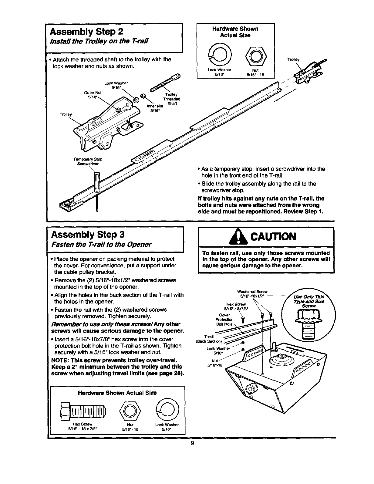
Assembly Step 2
Install the Trolley on the T-rail
• Attachthe threaded shafttothe trolleywith the
lock washer and nutsas shown.
Lock_/_s,her (_
Outer.Nuts/6_ _J_l_'_ _ .... ThreadedTr°'leYshaft
.o.le,
Temporary Stop
Screwddver
I
Hardware Shown
Actual Size
©@
Lock Washer Nut
5/16" 5/16" - 18
• As a temporary stop,insert a screwdriverintothe
hole inthe frontend of theT-rail,
• Slide thetrolleyassemblyalongthe railto the
screwdriverstop.
If trolley hits agalnat any nuts on the T-rell, the
bolts and nuts were attached from the wrong
aide and must be reposltloned. Review Step 1.
Assembly Step 3 ]
Fasten the T-rail to the Opener
I
• Place the opener on packing materialtoprotect
the cover. For convenience,put a supportunder
thecable pulley bracket.
• Remove the (2) 5/16"-1'8xl/2" washeredscrews
mountedin the top ofthe opener,
• Alignthe holesin the back sectionofthe T-rail with
the holesin the opener.
• Fasten the rail with the(2) washered screws
previouslyremoved, Tightensecurely.
Remember to use only these screws!Any other
screws will cause serious damage to the opener.
• Inserta 5/16"-18x718" hex screw intothe cover
protectionbolthole inthe T-rail as shown.Tighten
securelywith a 5/16" lockwasher and nut.
NOTE: This screw prevents trolley over-travel.
Keep a 2" minimum between the trolley and this
screw when adjusting travel limits (see page 28).
Hardware Shown Actual Size
Hex Screw Nut Lock Washer
5/16" * 18 x 7/8" 5/16"- 18 5/16"
CAUTION
To fasten rail, use only those screws mounted
In the top of the opener. Any other screws will
cause serious damage to the opener.
Washered Screw
5/16"-18xi/2" -
HexScr_
5/16"-18x7_"
CoVer t
Protection _
Bolt Hole _l
I-rail
Lock Washer
5/16 °
5/16"-
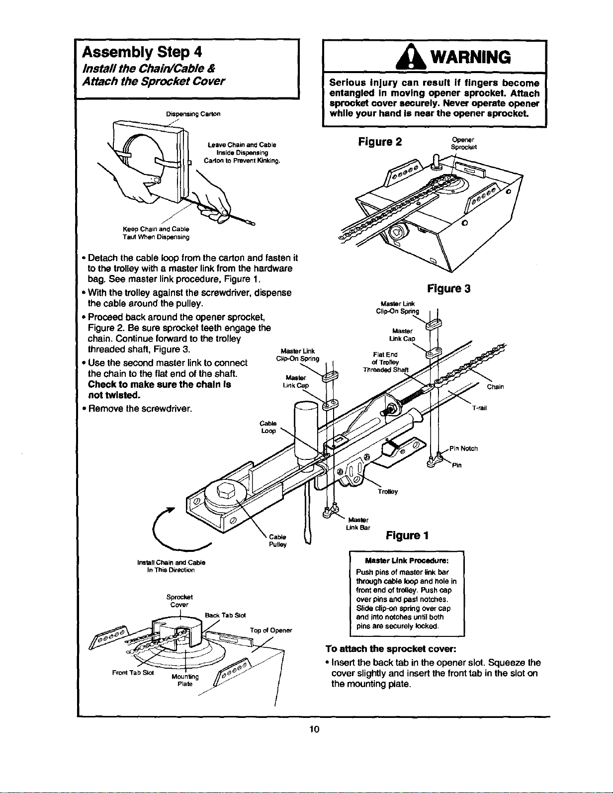
Assembly Step 4
Install the Chain/Cable &
Attach the Sprocket Cover
DiSpensingCarton
WARNING
Serious Injury can result If fingers become
entangled in moving opener sprocket. Attach
sprocket cover securely. Never operate opener
whlle your hand Is near the opener sprocket.
Leave Chain and Cable
Inside DiSpensing
Carton to Prevent Kinking.
/
Keep Chain and Cable
Taut When Dispensing
• Detach the cable loopfrom thecarton and fastenit
tothe trolleywitha master linkfrom the hardware
I bag. See masterlinkprocedure,Figure 1,
• Withthe trolleyagainstthe screwdriver,dispense
the cable aroundthe pulley.
• Proceed bsckaround the opener sprocket,
Figure2. Be sure sprocketteeth engagethe
chain. Continueforwardto the trolley
threaded shaft, Figure3. MasterLink
• Use thesecond master linktoconnect c,pOnsl_ng
the chainto theflat end of the shaft. Master
Check to make sure the chain Is UnkCap
not twisted.
• Remove the screwdriver.
Cable
Figure 2 o.e_,
Sprocket
Master Link
Master
Link Cap
Flat End
Figure 3
Chain
Torail
Inata;lChain and CalVe
In ThiSDireutio_
Sprocket
Cover
Back Tab Slot
FrOntTab Slot
Mounting
Plate
f
Cable
Pulley
Trolley
Top _ Opener
Link Bar
Figure I
Master Link PrOcedure:
Push pins of master link bar
throughcable loopand hole in
front end of trolley. Push cap
over pins and past notches.
Slide clip-onspdng over cap
and into notches untilboth
pins are securely locked,
To attach the sprocket cover:
• Insertthe backtab inthe opener slot.Squeeze the
cover slightlyand insertthe fronttab in the sloton
the mountingplate.
10
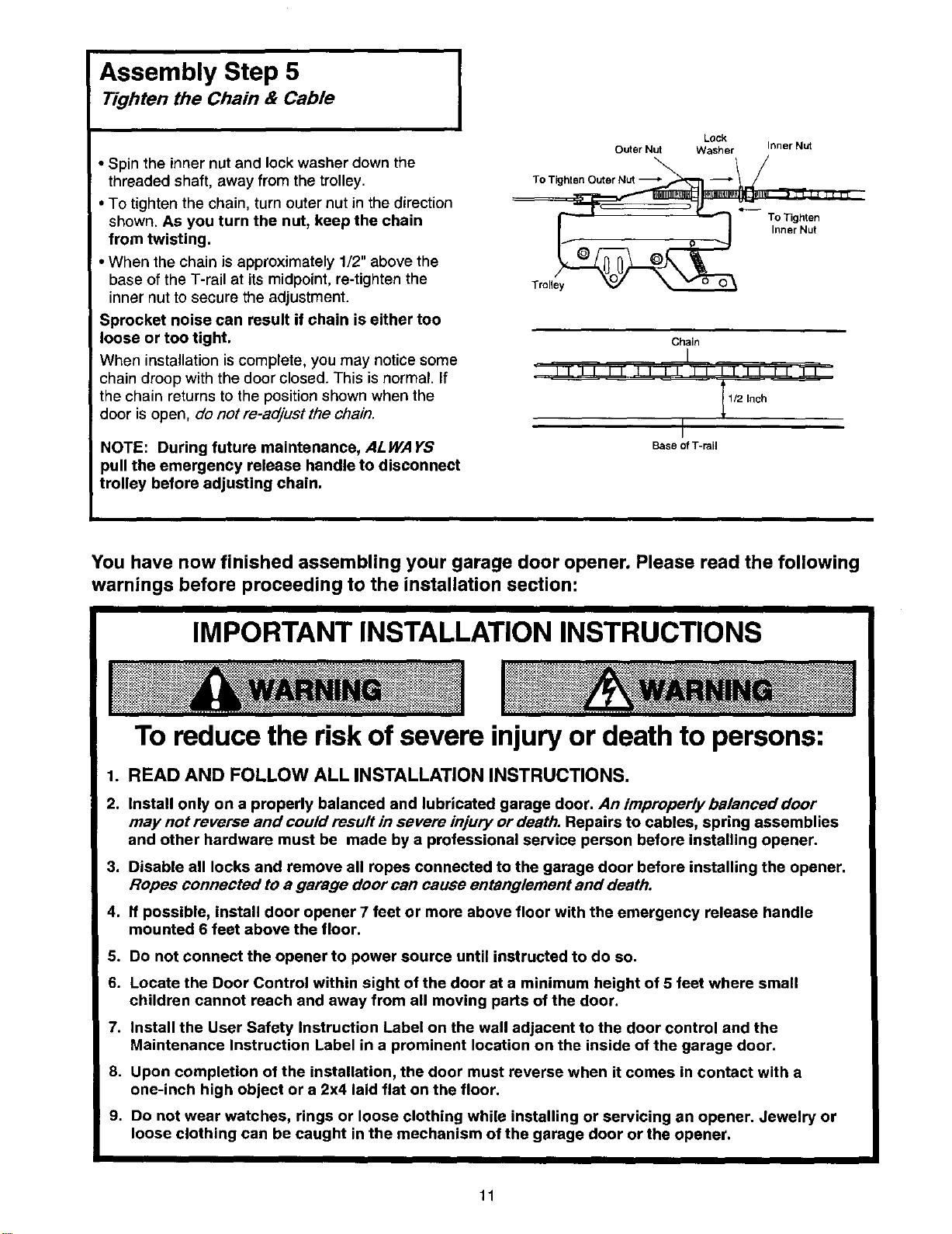
Assembly Step 5
Tighten the Chain & Cable
• Spin the inner nut and lock washer down the
threaded shaft, away from the trolley.
• To tighten the chain, turn outer nut in the direction
shown. As you turn the nut, keep the chain
from twisting.
• When the chain is approximately 1/2" above the
base of the T-rail at its midpoint, re-tighten the
inner nut to secure the adjustment.
Sprocket noise can result if chain is either too
loose or too tight.
When installation iscomplete, you may notice some
chain droop with the door closed. This isnormal. If
the chain returns to the position shown when the
door is open, do not re-adjust the chain.
NOTE: During future maintenance, ALWAYS
oull the emergency release handle to disconnect
trolley before adjusting chain.
I
Lock
Outer Nut Washer Inner Nut
To Tighten Outer Nut ---_ _ IIH_L_
Inner Nut
o o
Troll
Chain
I/2 Inch
I
Base of T-rail
You have now finished assembling your garage door opener. Please read the following
warnings before proceeding to the installation section:
IMPORTANT INSTALLATION INSTRUCTIONS
To reduce the risk of severe injuryor death to persons:
1. READ AND FOLLOW ALL INSTALLATION INSTRUCTIONS.
2. Install only on a properly balanced and lubricated garage door. An improperly balanced door
may not reverse and could result in severe injury or death. Repairs to cables, spring assemblies
and other hardware must be made by a professional service person before installing opener.
3. Disable all locks and remove all ropes connected to the garage door before installing the opener.
Ropes connected to a garage door can cause entanglement and death.
4. If possible, install door opener 7 feet or more above floor with the emergency release handle
mounted 6 feet above the floor.
5. Do not connect the opener to power source until instructed to do so.
6. Locate the Door Control within sight of the door at a minimum height of 5 feet where small
children cannot reach and away from all moving parts of the door.
7. Install the User Safety Instruction Label on the wall adjacent to the door control and the
Maintenance Instruction Label in a prominent location on the inside of the garage door.
8. Upon completion of the installation, the door must reverse when it comes in contact with a
one-inch high object or a 2x4 laid flat on the floor.
9. Do not wear watches, rings or loose clothing while installing or servicing an opener. Jewelry or
loose clothing can be caught in the mechanism of the garage door or the opener,
11
Installation Section: Pages 12 - 27
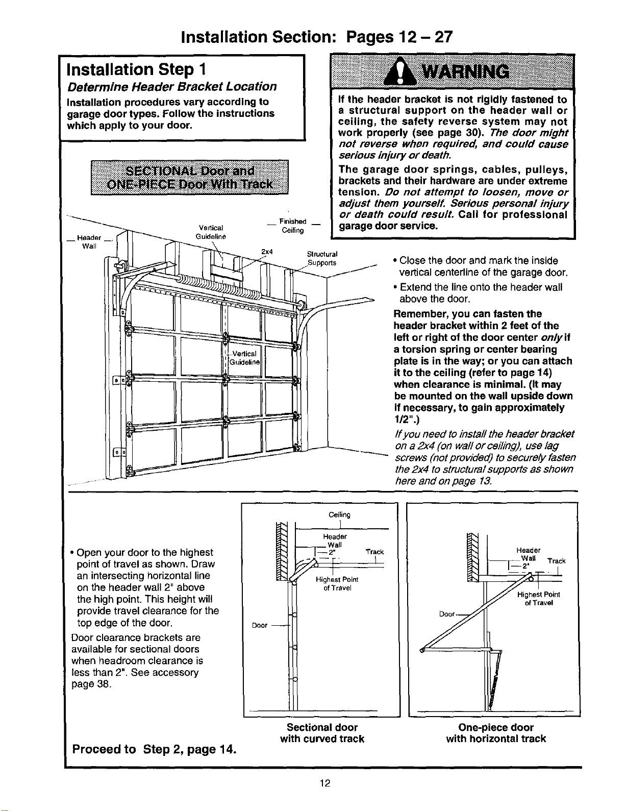
Installation Step I
Determine Header Bracket Location
Installation procedures vary according to
garage door types• Follow the instructions
which apply to your door.
__ Finished __
_ -""'_ "'--_ Vedical Ceiling
__ Header --
Wall
If the header bracket is not rigidly fastened to
a structural support on the header wall or
ceiling, the safety reverse system may not
work properly (see page 30). The door might
not reverse when required, and could cause
serious injury or death.
The garage door springs, cables, pulleys,
brackets and their hardware are under extreme
tension. Do not attempt to loosen, move or
adjust them yourself. Serious personal injury
or death could result. Call for professional
garage door service.
Guideline
Supports _ • Close the door and mark the inside
Ill-'_"-_--f'-_ vertical centerline of the garage door.
III I II 1 • Extend the line onto the header wall
__)_JJ_ _ above the door.
I[',l _F'fl Remember, you can fasten the
U_I _1 {1_ I header bracket within 2 feet of the
_L...._ ! I left or right of the door center only if
_;_Vertical _ ['---_ I I a torsion spring or center bearing
I1',{_i_ll I III I plate is in the way; or you can attach
_- II1_ I HI { it to the ceiling (refer to page 14)
_{ [ [ when clearance is minimal• (It may
III IIII I be mounted on the wall upside down
Ill _ I I if necessary, to gain approximately
_I IIt I I Ifyou need to install the header bracket
III _ on a 2x4 (on wall or ceiling), use lag
_ _ screws (not provided) to securely fasten
the 2x4 to structural supports as shown
here and on page 13.
• Open your door to the highest
point of travel as shown. Draw
an intersecting horizontal line
on the header wall 2" above
the high point. This height will
provide travel clearance for the
top edge of the door.
Door clearance brackets are
available for sectional doors
when headroom clearance is
less than 2". See accessory
page 38.
Door--
Ceiling
! '
Header
--Fg °,
-- • Track
Highest Point
of Travel
Header
a_ Track
Highest Point
of Travel
Proceed to Step 2, page 14.
Sectional door
with curved track
One-piece door
with horizontal track
12
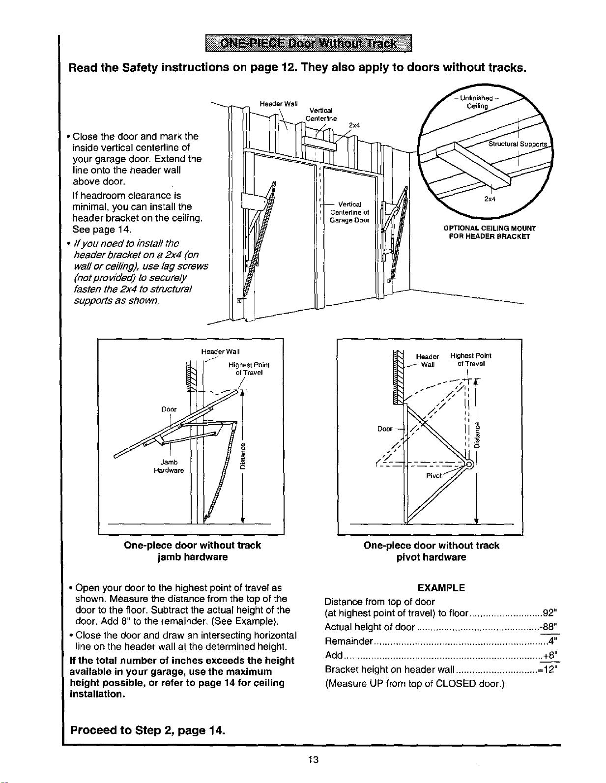
Read the Safety instructions on page 12. They also apply to doors without tracks.
• Close the door and mark the
inside vertical centerline of
your garage door. Extend the
line onto the header wall
above door.
If headroom clearance is
minimal, you can install the
header bracket on the ceiling.
See page 14.
• If you need to insta//the
header bracket on a 2x4 (on
we# or cei/ing), use lag screws
(not provided) to secure/y
fasten the 2x4 to structural
supports as shown.
Header Wall
Vedical
Centedine
2x4
OPTIONAL CEILING MOUNT
FOR HEADER BRACKET
Door
Jamb
Hardware
Header Wall
Highest Point
of Travel
/
8
One-piece door without track
jamb hardware
Header Highest Point
_- Wall of Travol
One-piece door without track
pivot hardware
• Open your door to the highest point of travel as
shown. Measure the distance from the top of the
door to the floor. Subtract the actual height of the
door• Add 8" to the remainder. (See Example).
• Close the door and draw an intersecting horizontal
line on the header wall at the determined height.
If the total number of inches exceeds the height
available in your garage, use the maximum
height possible, or refer to page 14 for ceiling
installation.
EXAMPLE
Distance from top of door
(at highest point of travel) to floor........................... 92"
Actual height of door ............................................. -88"
• tl
Remainder ................................................................ 4
Add ......................................................................... +8"
Bracket height on header wall ............................... 12"
(Measure UP from top of CLOSED door.)
Proceed to Step 2, page 14.
13
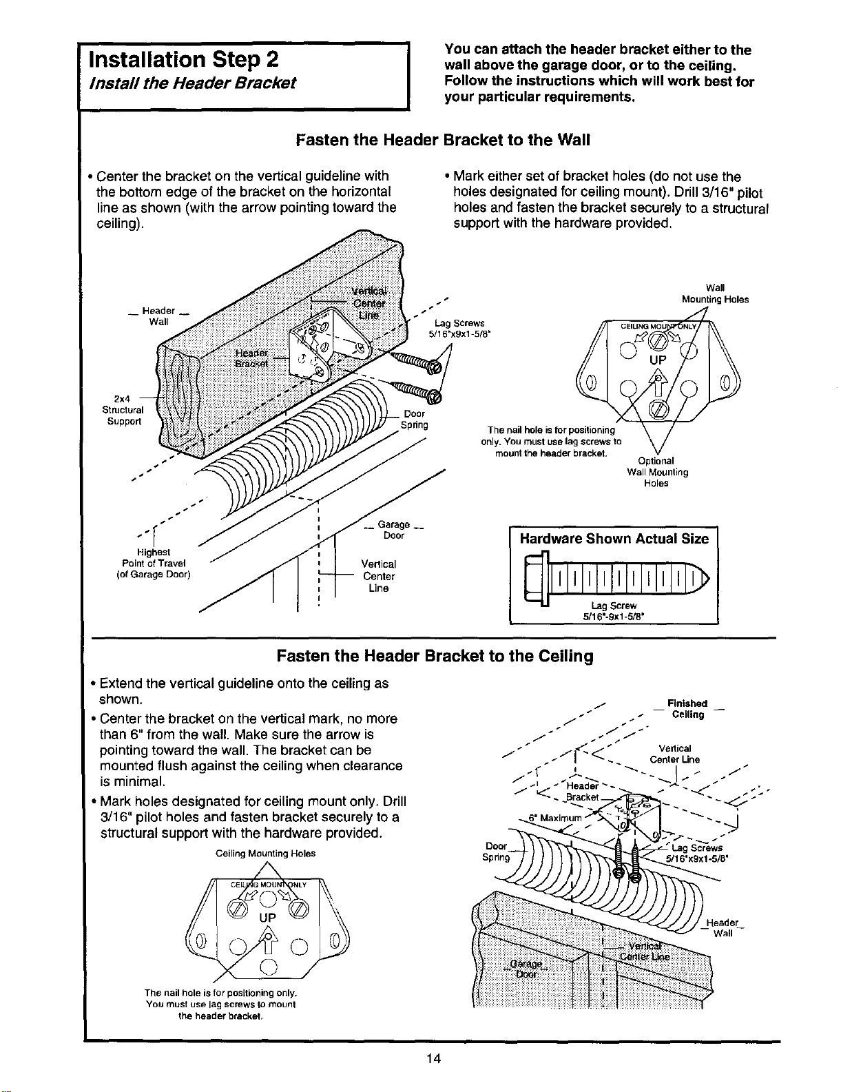
Installation Step 2 J
Install the Header Bracket
You can attach the header bracket either to the
wall above the garage door, or to the ceiling.
Follow the instructions which will work best for
your particular requirements.
Fasten the Header Bracket to the Wall
• Center the bracket on the vertical guideline with
the bottom edge of the bracket on the horizontal
line as shown (with the arrow pointing toward the
ceiling).
• Mark either set of bracket holes (do not use the
holes designated for ceiling mount). Drill 3/16" pilot
holes and fasten the bracket securely to a structural
support with the hardware provided.
_ Header _
Wall
Lag Screws
5/16'x9x1-5/8'
Wall
MountingHoles
2x4
Structural
Support
Highest
Point of Travel
(of Garage Door)
Door
Vertical
Center
Line
Door
The nail hole is for positioning
only. You must use lag screws to
mount the header bracket.
Optional
Wall Mounting
Holes
Hardware Shown Actual Size
l,l,I
5/16"-9xl -5/8"
Fasten the Header Bracket to the Ceiling
Extend the vertical guideline onto the ceiling as
shown.
Center the bracket on the vertical mark, no more
than 6" from the wall. Make sure the arrow is
pointing toward the wall. The bracket can be
mounted flush against the ceiling when clearance
is minimal.
• Mark holes designated for ceiling mount only. Drill
3/16" pilot holes and fasten bracket securely to a
structural support with the hardware provided.
Ceiling Mounting Holes
The nail hole is for positioning only.
You must use lag screws to mount
the header bracket,
Door
Spdng
Screws
5/16"x9x1-5/8"
eader
Wall
14
i i III
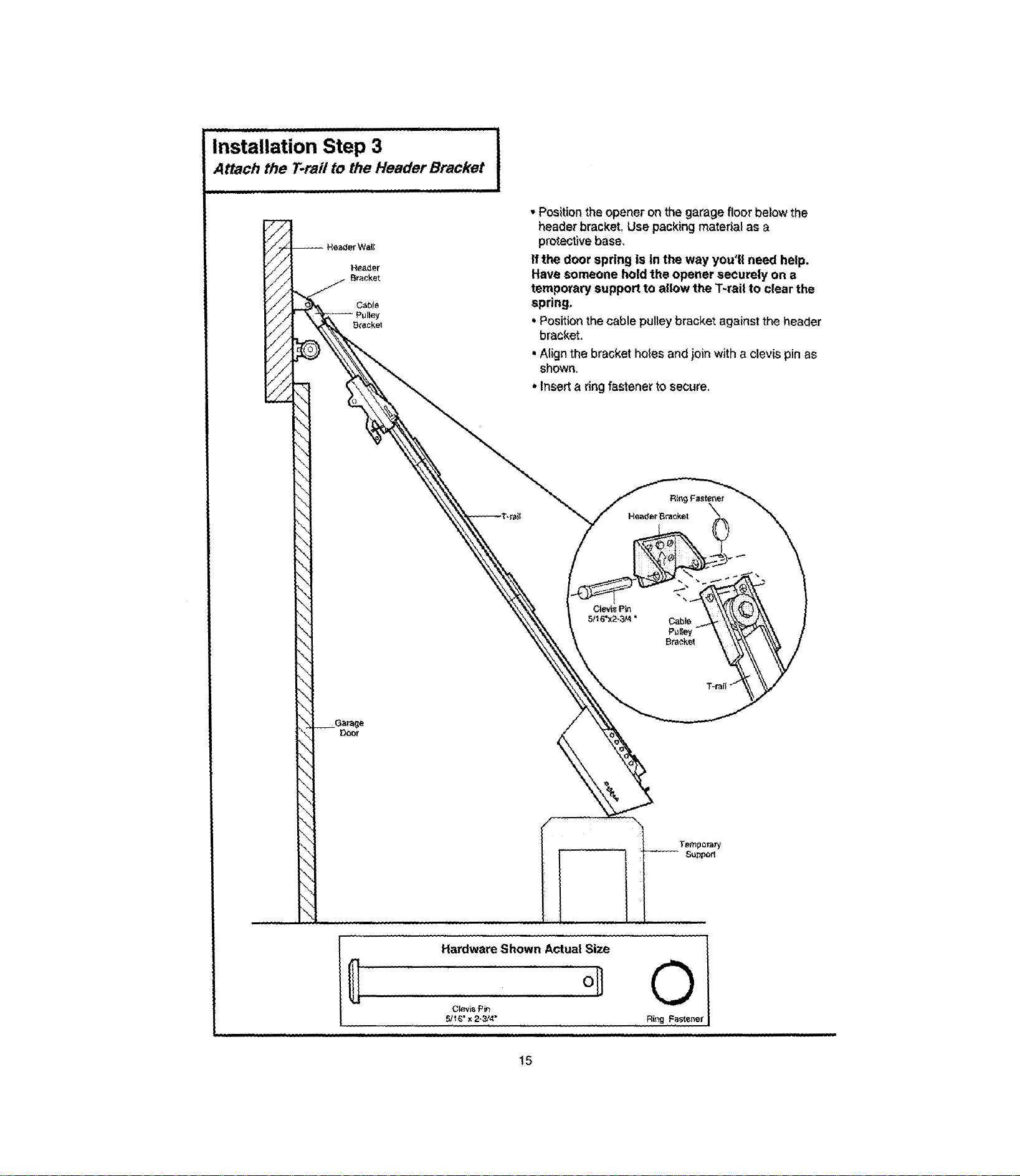
Installation Step 3
Attach the T.raii to the Header Bracket
• Position the opener on the garage floor below the
header bracket. Use packing material as a
protective base,
If the door spring is in the way you'll need help.
Have someone hold the opener securely on a
temporary support to allow the T-rail to clear the
spring,
• Position the cable pulley bracket against the header
bracket.
• Align the bracket holes and join with a clevis pin as
shown.
* Insert a ring fastener to secure.
Hardware Shown Actual Size
iiJ iiJ
°1
Clevi_ Pin
5/_" x 2- 314"
15
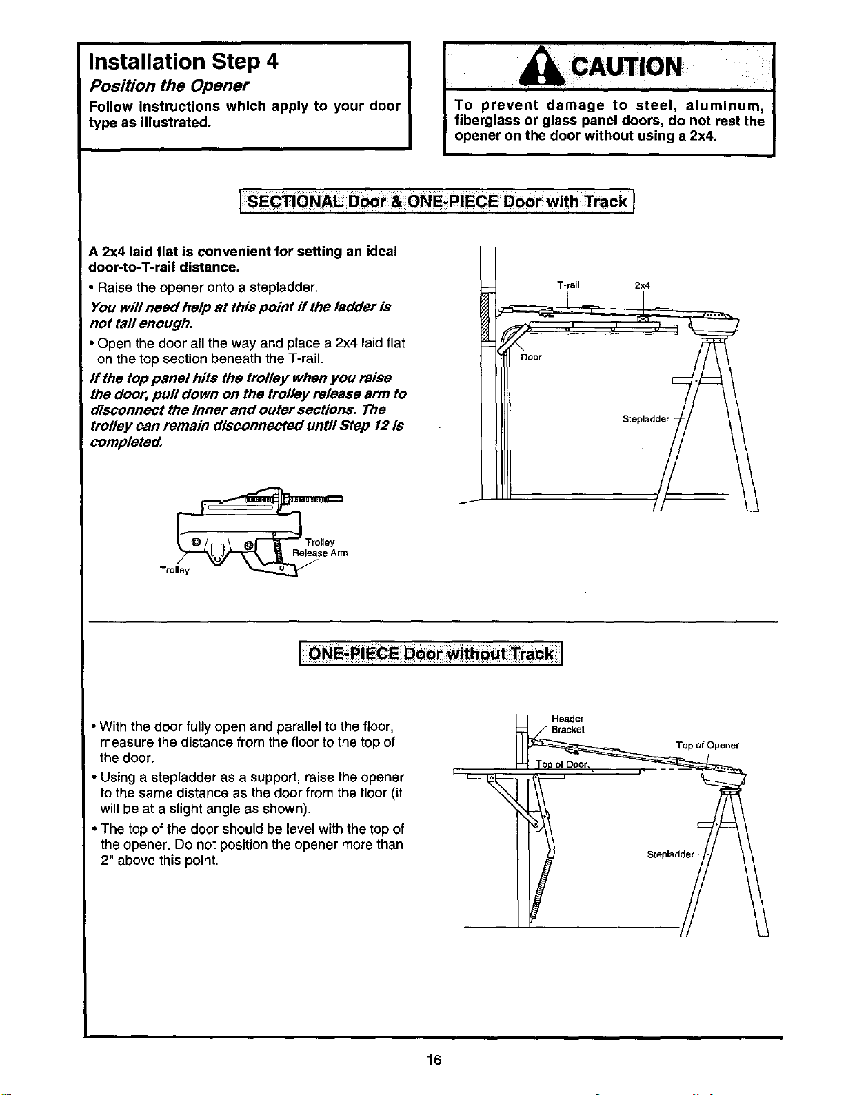
Installation Step 4
Position the Opener
Follow instructions which apply to your door
type as illustrated.
&CAUTION
To prevent damage to steel, aluminum,
fiberglass or glass panel doors, do not rest the
opener on the door without using a 2x4.
A 2x4 laid flat is convenient for setting an ideal
door-to-T-rail distance.
• Raise the opener onto a stepladder.
You will need help at this point if the ladder is
not tall enough.
• Open the door all the way and place a 2x4 laid flat
on timetop section beneath the T-rail.
If the top panel hits the trolley when you raise
the door, pull down on the trolley release arm to
disconnect the inner and outer sections. The
trolley can remain disconnected until Step 12 is
completed.
T-rail 2x4
Door
With the door fully open and parallel to the floor,
measure the distance from the floor to the top of
the door.
• Using a stepladder as a support, raise the opener
to the same distance as the door from the floor (it
will be at a slight angle as shown).
• The top of the door should be level with the top of
the opener. Do not position the opener more than
2" above this point.
Header
Bracket
Top of Opener
Stepbdder
16
Installation Step 5 I
Hang the Opener
I
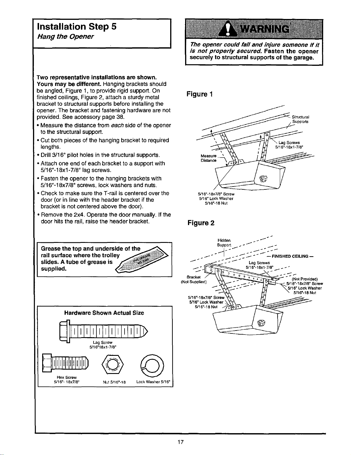
Two representative installations are shown.
Yours may be different. Hanging brackets should
be angled, Figure 1, to provide rigid support. On
finished ceilings, Figure 2, attach a sturdy metal
bracket to structural supports before installingthe
opener. The bracket and fastening hardware are not
_rovided. See accessory page 38.
• Measure the distance from each side ofthe opener
to the structural support.
• Cut both pieces of the hanging bracket to required
lengths.
• Drill 3/16" pilot holes in the structural supports.
• Attach one end of each bracket to a support with
5/16"-18xl -7/8" lag screws.
• Fasten the opener to the hanging brackets with
5/16"-18x7/8" screws, lock washers and nuts.
• Check to make sure the T-rail iscentered over the
door (or in line with the header bracket if the
bracket is not centered above the door).
• Remove the 2x4. Operate the door manually. If the
door hits the rail, raise the header bracket.
I
Grease the top and underside of the_ ]
rail surface where the trolley /__
I
slides. A tube of grease is /_7/
supplied.
Hardware Shown Actual Size
5/16"18xl-7/8"
Dl!Jlli!rl:!'HD© ©
5/16"- 18x7/8" Nut 5/16"-18 Lock Washer 5/16"
Figure 1
Suppods
Measure _
Distance
5/16'-18x7/8"Screw
5/16"LockWasher
5/16'-18 Nut
Figure 2
Hidden _ /
/
Support _-- _ _ _ _
I" _ _ / _ -- FINISHED CEILING --
___8° _.5/16"-18xl -7/8 ° _ _ _ "
_racke! / \__ - (No Provded)
(NotSuppl",d) _" - -/::---_"_ _ 5/16"_8x_/8"S_rew
5/16" Lock Washer
5/16"-18 Nut
5/16"- 18x7/8" Screw
5/16' Lock Washer
17
Installation Step 6 IInstall the Door Control
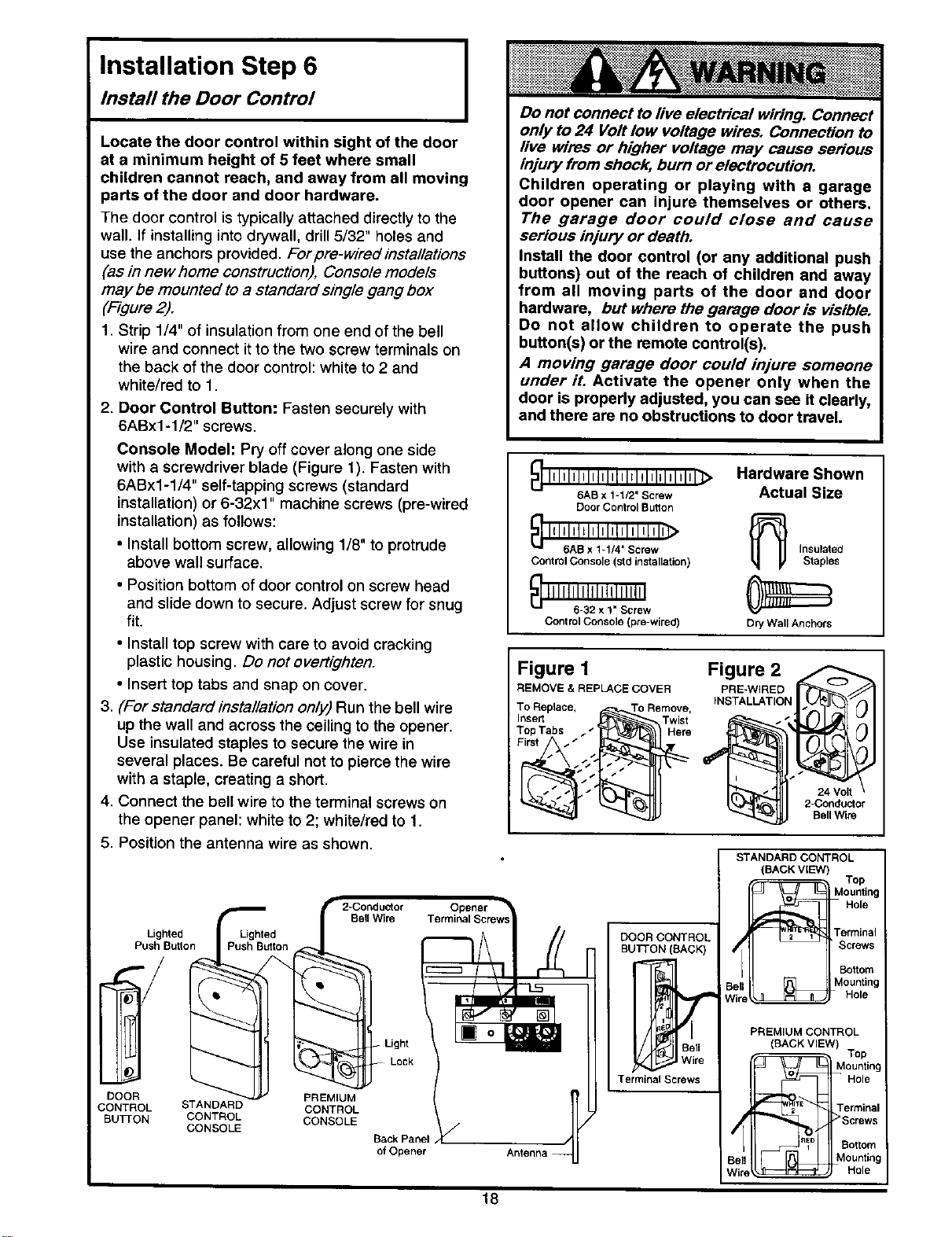
Locate the door control within sight of the door
at a minimum height of 5 feet where small
children cannot reach, and away from all moving
parts of the door and door hardware.
The door control is typically attached directly to the
wall. If installing into drywall, drill 5/32" holes and
use the anchors provided. For pre-w/red installations
(as in new home construction), Console models
may be mounted to a standard single gang box
('Figure 2).
1. Strip 1/4" of insulation from one end of the bell
wire and connect it to the two screw terminals on
the back of the door control: white to 2 and
white/red to 1.
2. Door Control Button: Fasten securely with
6ABx1-1/2" screws•
Console Model: Pry off cover along one side
with a screwdriver blade (Figure 1). Fasten with
6ABx1-1/4" self-tapping screws (standard
installation) or 6-32xl" machine screws (pre-wired
installation) as follows:
• Install bottom screw, allowing 1/8" to protrude
above wall surface.
• Position bottom of door control on screw head
and slide down to secure. Adjust screw for snug
fit.
• Install top screw with care to avoid cracking
plastic housing. Do not overt/ghten.
• Insert top tabs and snap on cover.
3. (For standard installation only) Run the bell wire
up the wall and across the ceiling to the opener.
Use insulated staples to secure the wire in
several places. Be careful not to pierce the wire
with a staple, creating a short.
4• Connect the bell wire to the terminal screws on
the opener panel: white to 2; white/red to 1.
5. Position the antenna wire as shown.
Lighted
Push Button
DOOR
CONTROL
BUTFON
Lighted
Push Button
STANDARD
CONTROL
CONSOLE
PREMIUM
CONTROL
CONSOLE
Light
Lock
Back Panel
of Opener
Do not connect to live electrical wiring. Connect
only to 24 Volt low voltage wires. Connection to
live wires or higher voltage may cause setYous
injury from shock, burn or electrocution.
Children operating or playing with a garage
door opener can injure themselves or others.
The garage door could close and cause
serious injury or death.
Install the door control (or any additional push
buttons) out of the reach of children and away
from all moving parts of the door and door
hardware, but where the garage door is visible.
Do not allow children to operate the push
button(s) or the remote control(s).
A moving garage door could injure someone
under it. Activate the opener only when the
door is properly adjusted, you can see it clearly,
and there are no obstructions to door travel.
_ I_lllllllllllllll_ltl_lllllllll)
6AB x 1-1/2" Screw
Door Control Button
_ IIlll=lll=l=l=lilllilill_
6AB x 1-1/4" Screw Insulated
Control Console (std installation) Staples
Control Console (pr6-wired) Dry Wall Anchors
Hardware Shown
Actual Size
Figure 1
REMOVE & REPLACE COVER
To Replace, _r_!s!TO Remove,
Insert Twist
Top Tabs _ - Here
First_,_,. __"__'_"_
Figure 2
PRE-WlRED
INSTALLATION
24 Volt
2-Conductor
Bell Wire
18
DOOR CONTROL
BUTTON (BACK)
Terminal Screws
STANDARD CONTROL
(BACK VIEW)
_ Top
_Mounting
Hole
Terminal
Screws
Bottom
&_ Mounting• Hole
PREMIUM CONTROL
(RACK VIEW)
Top
..... Mounting
_ - Hole
_;_n E'P'_ Terminal
_1 """_"_ >Screws
..... Bottom
Bell " " " Mounting
Wire _ Hole
6. Attach the User Safety Instruction label to the wall
near the door control, and the Maintenance
Instruction label in a prominent location on the
inside of the garage door.
Page 32 explains how to use the door control.
Do NOT connect the power and operate the
opener at this time. The trolley will travel to the
full open position but will not return to the
close position until the sensor beam is
connected and properly aligned.
See Safety Reversing Sensor instructions
beginning on page 21.
Installation Step 7
Install the Light and the Lens
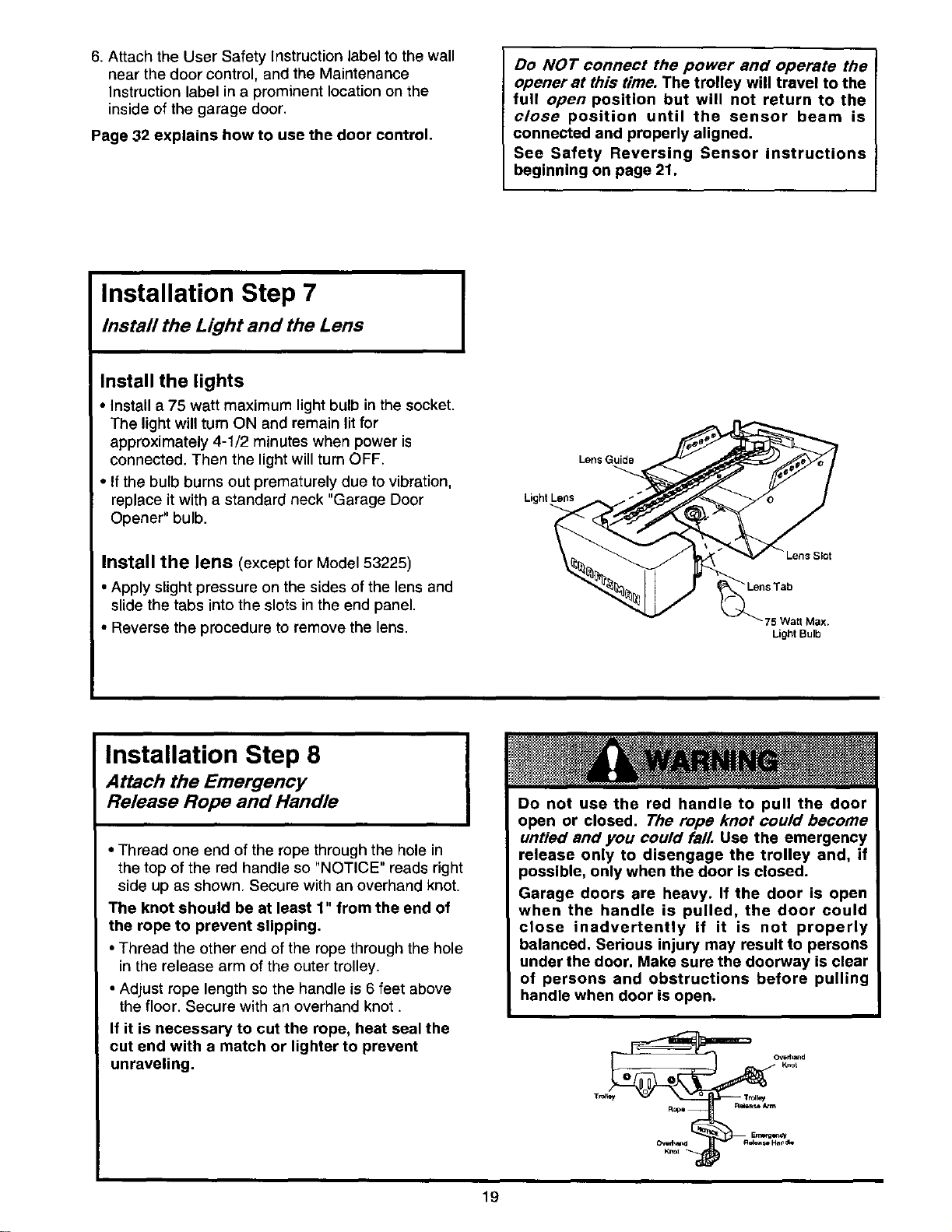
Install the lights
• Install a 75 watt maximum light bulb in the socket.
The light will turn ON and remain litfor
approximately 4-1/2 minutes when power is
connected. Then the light will turn OFF.
• If the bulb burns out prematurely due to vibration,
replace itwith a standard neck "Garage Door
Opener" bulb.
Install the lens (except for Model 53225)
• Apply slight pressure on the sides of the lens and
slide the tabs into the slots in the end panel.
• Reverse the procedure to remove the lens.
I
Lens Guide
Light
_k_t
75Wa_ Max.
Ught Bulb
Installation Step 8
Attach the Emergency
Release Rope and Handle
• Thread one end of the rope through the hole in
the top of the red handle so "NOTICE" reads right
side up as shown. Secure with an overhand knot.
The knot should be at least 1" from the end of
the rope to prevent slipping.
• Thread the other end of the rope through the hole
in the release arm of the outer trolley.
• Adjust rope length so the handle is 6 feet above
the floor. Secure with an overhand knot.
If it is necessary to cut the rope, heat seal the
cut end with a match or lighter to prevent
unraveling.
Do not use the red handle to pull the door
open or closed. The rope knot could become
untied and you could falL Use the emergency
release only to disengage the trolley and, if
possible, only when the door is closed.
Garage doors are heavy. If the door is open
when the handle is pulled, the door could
close inadvertently if it is not properly
balanced. Serious injury may result to persons
under the door. Make sure the doorway is clear
of persons and obstructions before pulling
handle when door is open.
Ropa -- _so Arm
Knot
19
Installation Step 9 J
Electrical Requirements
I
To reduce the risk of electric shock, your garage
door opener has a grounding type plug with a third
grounding pin. This plug will onlyfit into a grounding
type outlet.
If the plug doesn't fit into the outlet you have,
contact a qualified electrician to install the proper
outlet.
I To avoid installation difficulties, I
do not run the opener at this time.
To prevent electrocution or fire, installation
and wiring must be in compliance with local
electrical and building codes.
Do NOTuse an extension cord, 2-wire adapter,
or change the plug in any way to make it fit
your outlet.
Right Wrong
If permanent wiring is required by your local code, refer to the following procedure:
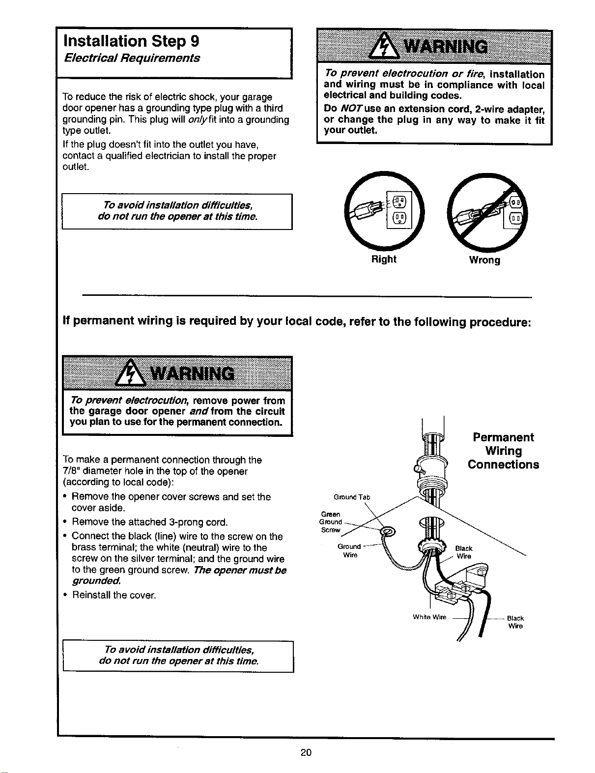
To make a permanent connection through the
7/8" diameter hole in the top of the opener
(according to local code):
• Remove the opener cover screws and set the
cover aside.
• Remove the attached 3-prong cord.
• Connect the black (line) wire to the screw on the
brass terminal; the white (neutral) wire to the
screw on the silver terminal; and the ground wire
to the green ground screw. The opener must be
grounded.
• Reinstall the cover.
Ground Tab
Green
Ground
Scr6w
Wire
White Wire
Permanent
Wiring
Connections
Wire
To avoid installation difficulties,
do not run the opener at this time.
2O
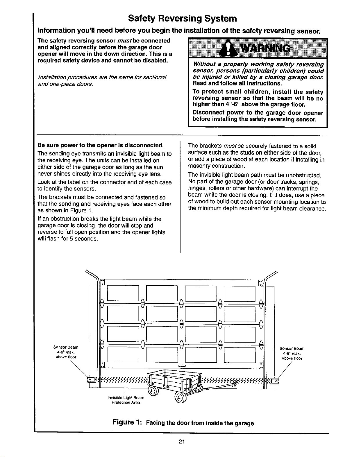
Safety Reversing System
and aligned correctly before the garage door
opener will move in the down direction. This is a
required safety device and cannot be disabled.
installation procedures are the same for sectional
and one-piece doors.
Information you'll need before you begin the installation of the safety reversing sensor.
The safety reversing sensor mustbe connected
Without a properly working safety reversing
sensor, persons (particularly children) could
be injured or killed by a closing garage door.
Read and follow all instructions.
To protect small children, install the safety
reversing sensor so that the beam will be no
higher than 4"-6" above the garage floor.
Disconnect power to the garage door opener
before installing the safety reversing sensor.
Be sure power to the opener is disconnected.
The sending eye transmits an invisible light beam to
the receiving eye. The units can be installed on
either side of the garage door as long as the sun
never shines directly into the receiving eye lens.
Look at the label on the connector end of each case
to identify the sensors.
The brackets must be connected and fastened so
that the sending and receiving eyes face each other
as shown in Figure 1.
If an obstructionbreaks the light beam while the
garage door isclosing, the door will stop and
reverse to full open position and the opener lights
will flash for 5 seconds.
The brackets mustbe securely fastened to a solid
surface such as the studs on either side of the door,
or add a piece of wood at each location if installing in
masonry construction.
The invisible light beam path must be unobstructed.
No part of the garage door (or door tracks, springs,
hinges, rollers or other hardware) can interrupt the
beam while the door is closing, if it does, use a piece
of wood to build out each sensor mounting location to
the minimum depth required for light beam clearance.
Sensor Beam
4-6" max.
above floor
%
[-
Figure 1: Facing the door from inside the garage
21
Installation Step 10 I
Install the Safety Reversing Sensor
I
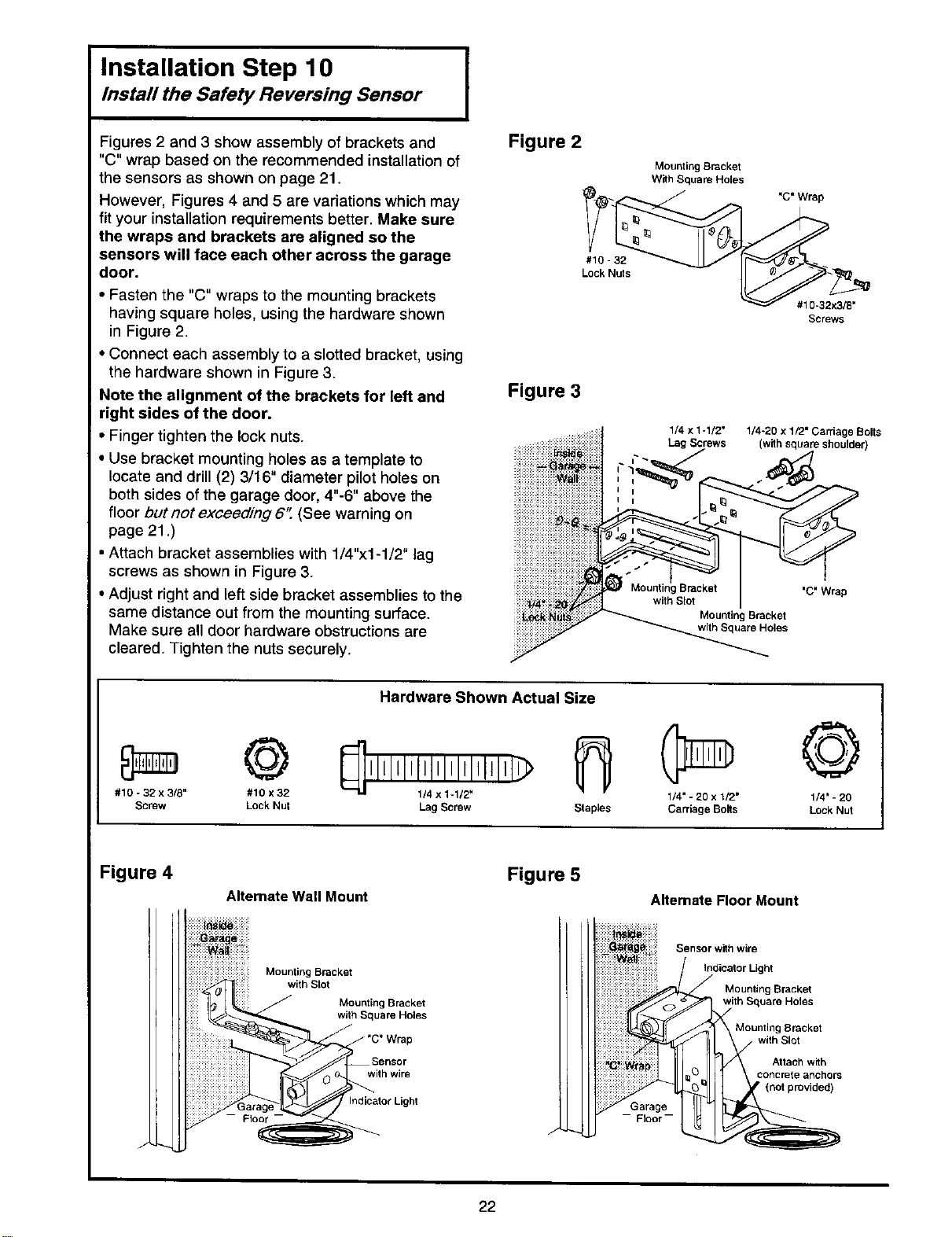
Figures 2 and 3 show assembly of brackets and
"C" wrap based on the recommended installation of
the sensors as shown on page 21.
However, Figures 4 and 5 are variations which may
fit your installation requirements better. Make sure
the wraps and brackets are aligned so the
sensors will face each other across the garage
door.
i Fasten the "C" wraps to the mounting brackets
having square holes, using the hardware shown
in Figure 2.
Connect each assembly to a slotted bracket, using
the hardware shown in Figure 3.
Note the alignment of the brackets for left and
right sides of the door.
• Finger tighten the lock nuts.
• Use bracket mounting holes as a template to
locate and drill (2) 3/16" diameter pilot holes on
both sides of the garage door, 4"-6" above the
floor but not exceeding 6" (See warning on
page 21 .)
• Attach bracket assemblies with 1/4"x1-1/2" lag
screws as shown in Figure 3.
• Adjust right and left side bracket assemblies to the
same distance out from the mounting surface.
Make sure all door hardware obstructions are
cleared. Tighten the nuts securely.
Figure 2
#10 - 32
Lock Nuts
Figure 3
Mounting Bracket
With Square Holes
1/4 x 1-1/2"
Lag Screws
Mounting Bracket
with Square Holes
"C" Wrap
#10-32x3/8"
Screws
1/4-20 x1/2"CarriageBolts
(withsquareshoulder)
'C" Wrap
©
#10 - 32 x 3/8" #10 x32
Screw Lock Nut
Hardware Shown Actual Size
©
1/4" - 20 x 1/2" 1/4" - 20
Lag Screw Staples Carriage Bolts Lock Nut
Figure 4
Alternate Wall Mount
Mounting Bracket
with Blot
Mounting Bracket
with Square Holes
with wire
Indicator Light
Figure 5
/
Alternate Floor Mount
iiiiiii iiill
Floor --
Sensor with wire
Indicator Light
_" Mounting Bracket
with Square Holes
Mounting Bracket
with Slot
Attach with
concrete anchors
22
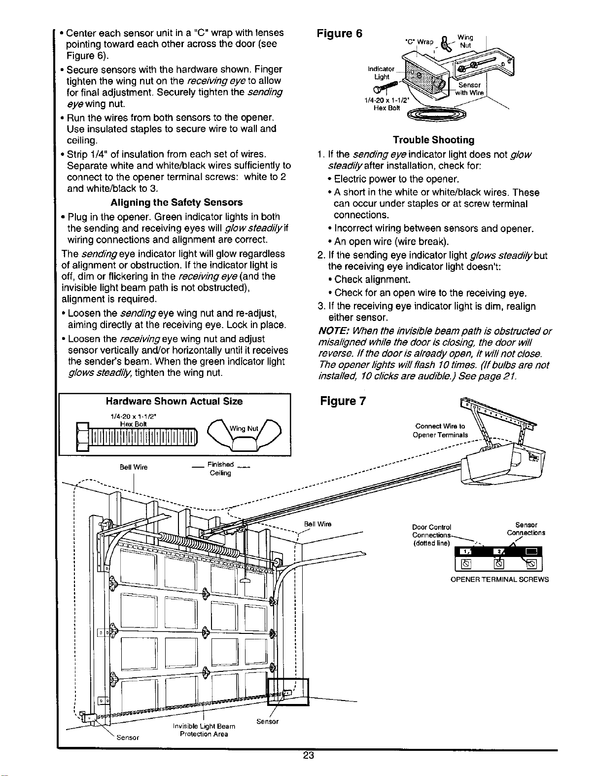
• Centereachsensorunitina"C"wrapwithtenses
pointingtowardeachotheracrossthedoor(see
Figure6).
•Securesensorswiththehardwareshown.Finger
tightenthewingnutonthereceiving eye to allow
for final adjustment. Securely tighten the sending
eye wing nut.
• Run the wires from both sensors to the opener.
Use insulated staples to secure wire to wall and
ceiling.
• Strip 1/4" of insulation from each set of wires.
Separate white and white/black wires sufficiently to
connect to the opener terminal screws: white to 2
and white/black to 3.
Aligning the Safety Sensors
• Plug in the opener. Green indicator lights in both
the sending and receiving eyes will g/owsteadilyif
wiring connections and alignment are correct.
The sending eye indicator light will glow regardless
of alignment or obstruction. If the indicator light is
off, dim or flickering in the receiving eye (and the
invisible light beam path is not obstructed),
alignment is required.
• Loosen the sendingeye wing nut and re-adjust,
aiming directly at the receiving eye. Lock in place.
• Loosen the receiving eye wing nut and adjust
sensor vertically and!or horizontally until it receives
the sender's beam. When the green indicator light
glows steadily, tighten the wing nut.
Figure 6
'C" Wra
Indicator
1/4-20 x 1-1/2"
Hex Bolt
Trouble Shooting
1. If the sending eye indicator lightdoes not glow
steadily after installation, check for:
• Electric power to the opener.
• A short in the white or white/black wires. These
can occur under staples or at screw terminal
connections.
• Incorrect wiring between sensors and opener.
• An open wire (wire break).
2. If the sending eye indicator light glows stead/lybut
the receiving eye indicator light doesn't:
• Check alignment.
• Check for an open wire to the receiving eye.
3. If the receiving eye indicator light is dim, realign
either sensor.
NOTE: When the invisible beam path is obstructed or
m/sa/igned while the door is closing, the door will
reverse, ff the door is already open, it will not close.
The opener lights will flash 10times. ('lfbulbs are not
installed, 10 clicks are audible.) See page 21.
Figure 7
Connect Wire to
Opener Terminals
Bell Wire Door Control
..... "_ Connections_
(dotted line) I ""
[]
Sensor
Connections
/
OPENERTERMINALSCREWS
Sensor
Invisible Light Beam
Protection Area
23
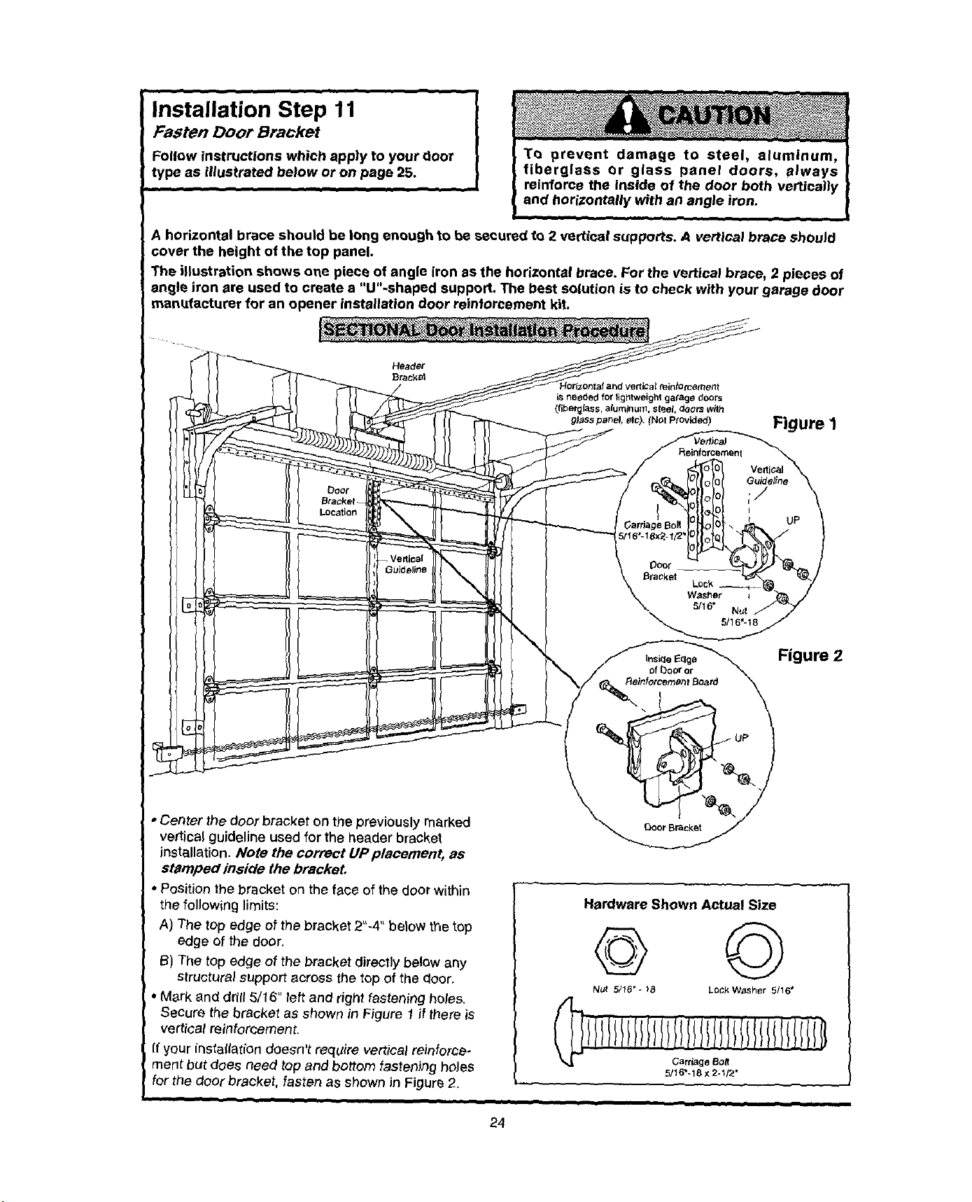
Installation Step 11
Fasten Door Bracket
Follow instructions which apply to your door
type as illustrated below or on page 25.
T_ prevent damage to steel, aluminum,
fiberglass or glass panel doors, always
reinforce the inside of the door both vertlcany
and horizontally with an angle iron.
A horizontal brace should be long enough to be secured to 2 vertical supports. A vertical brace should
cover the height of the top panel.
The illustration shows one piece of angle iron as the horizontal brace. For the vertical brace, 2 pieces of
angle iron are used to create a "U"-shaped support. The best solution is to check with your garage door
manufacturer for an opener installation door reinforcement kit.
• Center the door bracket on the previously marked
vertical guideline used for the header bracket
installation. Note the correct UP plaeement, as
stamped inside the bracket.
• Position the bracket on the face of the door within
the following limits:
A) The top edge of the bracket 2"-4" betow the top
edge of the door.
I_) The top edge of the bracket directly below any
Structural support across the top of the door.
• Mark and drill 5/16" left and right fastening holes.
Secure the bracket as shown in Figure I if there is
vertical reinforcement.
If your instaltation doesn't require vertical reinforce-
ment but does need top and bottom fastening hoJes
for the door bracket, fasten as shown in Figure 2.
Figure 2
Hardware Shown Actual Size
© ©
Nut 5/16"-18 LOCkW_sher 5/16'
ll llllllll/lililllllllIlllll ili/
Carriage 8o_
5/t 6"-18 x 2-1/2'
24
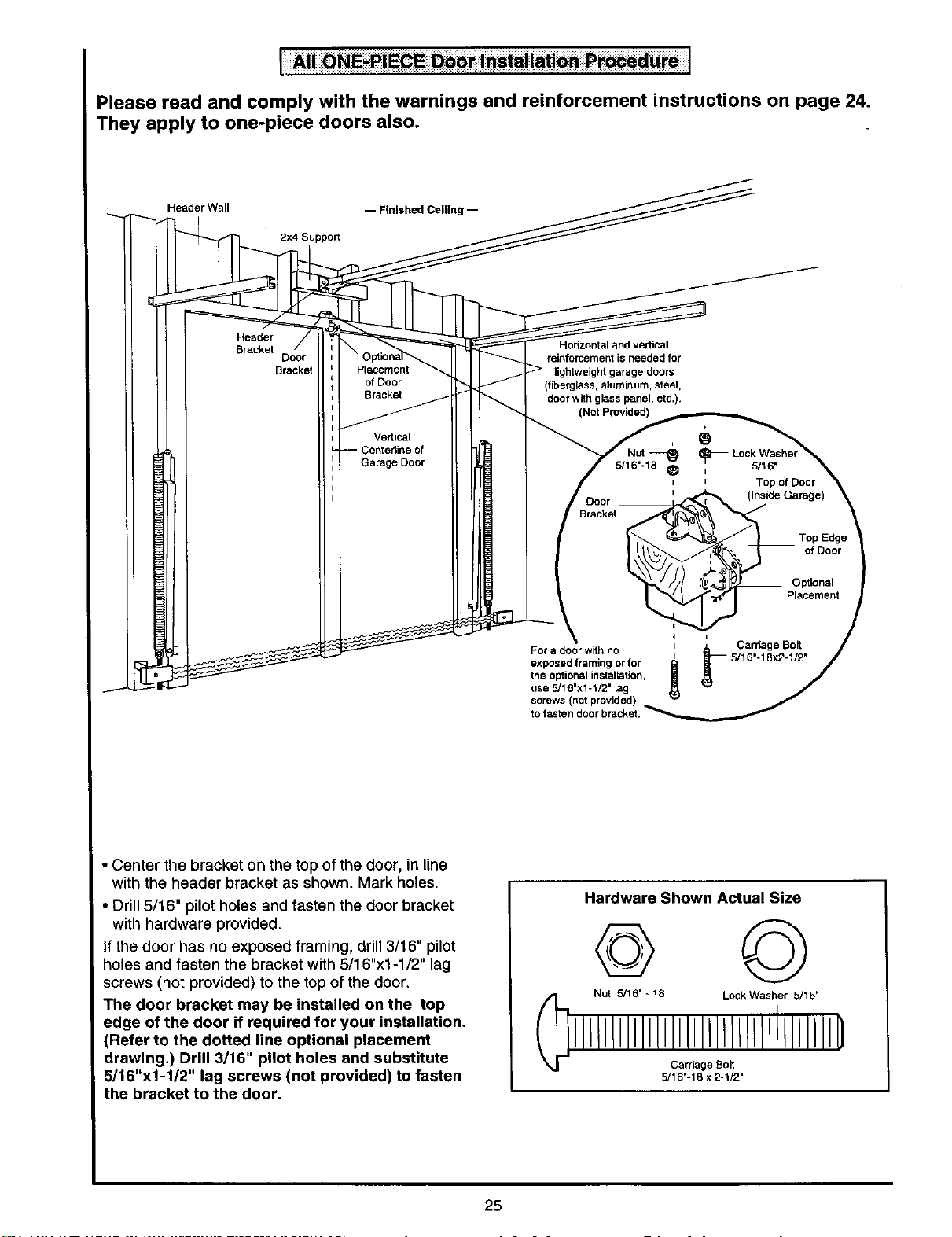
Please read and comply with the warnings and reinforcement instructions on page 24.
They apply to one-piece doors also.
Header Wail
-- Finished Ceiling --
2x4 Support
Header
Bracket
Bracket
Placement
of Door
Bracket
Vedical
;entedine of
Garage Door
Horizontal and vertical
reinforcement is needed for
lightweight garage doors
(fiberglass, aluminum, steel,
door with glass panel, etc.).
(Not Provided)
e
i
Nut _
5/16'-18 _ I
I
I
Door t
Bracket
=
For a door with no _ _ Carriage Bolt
exposed framing or for _ [ 5/16=-18x2-1/2"the optional installation,
use 5/16"x1-1/2" !ag
screws (not provided)
5/16"
Top of Door
(inside Garage)
___ Top Edge
of Door
__ Optional
Placement
• Center the bracket on the top of the door, in line
with the header bracket as shown. Mark holes.
• Drill 5/16" pilot holes and fasten the door bracket
with hardware provided.
If the door has no exposed framing, drill 3/16" pilot
holes and fasten the bracket with 5/16"x1-1/2" lag
screws (not provided) to the top of the door.
The door bracket may be installed on the top
edge of the door if required for your installation.
(Refer to the dotted line optional placement
drawing.) Drill 3/16" pilot holes and substitute
5/16"x1-1/2" lag screws (not provided) to fasten
the bracket to the door.
Hardware Shown Actual Size
© ©
Nut 5/16' * 18 LockWasher 5/16"
Cardage Bolt
5/16"-16 x 2-1/2"
25
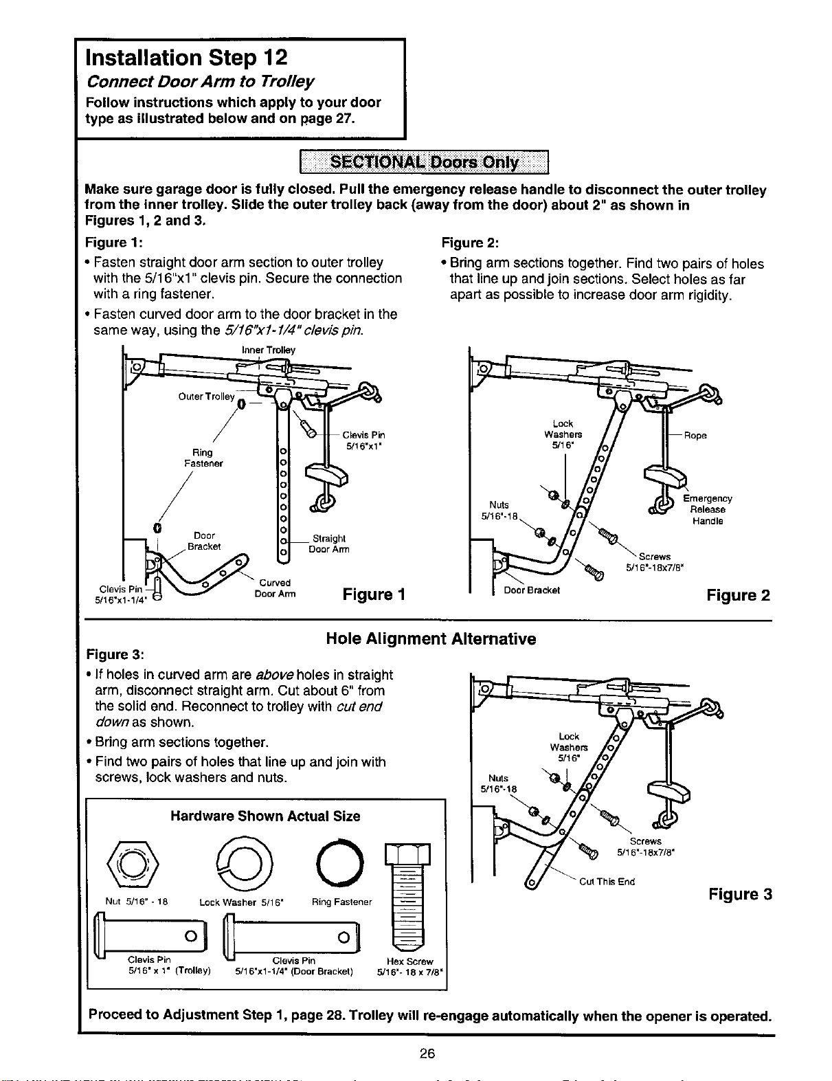
Installation Step 12
Connect Door Arm to Trolley
Follow instructions which apply to your door
type as illustrated below and on page 27.
[i31iiii!iiiiSi l! il iiiiiiiiiii i iiiTiiiiiiiiiTiiiii!l
Make sure garage door is fully closed. Pull the emergency release handle to disconnect the outer trolley
from the inner trolley. Slide the outer trolley back (away from the door) about 2" as shown in
Figures 1, 2 and 3.
Figure 1:
• Fasten straight door arm section to outer trolley
with the 5/16"xl" clevis pin. Secure the connection
with a ring fastener.
• Fasten curved door arm to the door bracket in the
same way, using the 5/16")(1-1/4" clevis pin.
Figure 2:
• Bring arm sections together. Find two pairs of holes
that line up and join sections. Select holes as far
apart as possible to increase door arm rigidity.
Inner Trolley
/
BDoor Strai_A_
c'_v_.P]7"-__ DcU"_ Figure 1
Screws
5/16"-18x7/8'
Door Bracket
Emergency
Release
Handle
Figure 2
Hole Alignment Alternative
Figure 3:
• If holes in curved arm are above holes in straight
arm, disconnect straight arm. Cut about 6" from
the solid end. Reconnect to trolley with cutend
down as shown.
• Bring arm sections together.
Find two pairs of holes that line up and join with
screws, lock washers and nuts.
Hardware Shown Actual Size
© @o
Nut 5/16" - 18 Lock Washer 5/16 = Ring Fastener
5/16" x 1" (Trolley) 5/16"x1-1/4" (Door Bracket)
Hex Screw
5/16'- 18 x 7/8"
Lock
Washers
5/16"
Screws
O_ " Cut This End
Figure 3
Proceed to Adjustment Step 1, page 28. Trolley will re-engage automatically when the opener is operated.
26
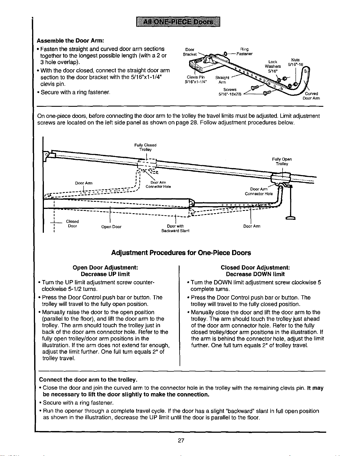
Assemble the Door Arm:
• Fasten the straight and curved door arm sections
together to the longest possible length (with a 2 or
3 hole overlap).
• With the door closed, connect the straight door arm
section to the door bracket with the 5/16"xl-1/4"
clevis pin.
• Secure with a ring fastener.
Door
Clevis Pin
5/16"x1-1/4"
Ring
Straight
Arm
Screws
5/16"-18x7/8
Lock
Washem
5/16"
Nuts
5/16"-18
Door Arm
On one-piece doors, before connecting the door arm to the trolley the travel limits must be adjusted. Limitadjustment
screws are located on the left side panel as shown on page 28. Follow adjustment procedures below.
Fully Closed
Trolley
Fulty Open
Trolley
I
I 1 -'-J"
Closed
Door Open Door Door with
i
i Backward Slant
Door Arm
Connector Hole
Door Arm
Adjustment Procedures for One-Piece Doors
Open Door Adjustment:
Decrease UP limit
• Turn the UP limit adjustment screw counter-
clockwise 5-1/2 turns.
• Press the Door Control push bar or button. The
trolley will travel to the fully open position.
• Manually raise the door to the open position
(parallel to the floor), and liftthe door arm to the
trolley. The arm should touch the trolley just in
back of the door arm connector hole. Refer to the
fully open trolley/door arm positions in the
illustration. If the arm does not extend far enough,
adjust the limit further. One full turn equals 2" of
trolley travel.
Closed Door Adjustment:
Decrease DOWN limit
* Turn the DOWN limit adjustment screw clockwise 5
complete turns.
° Press the Door Control push bar or button. The
trolley will travel to the fully closed position.
, Manually close the door and lift the door arm to the
trolley. The arm should touch the trolley just ahead
of the door arm connector hole. Refer to the fully
closed trolley/door arm positions in the illustration. If
the arm is behind the connector hole, adjust the limit
further. One full turn equals 2" of trolley travel.
Connect the door arm to the trolley.
• Close the door and join the curved arm to the connector hole in the trolley with the remaining clevis pin. It may
be necessary to lift the door slightly to make the connection.
• Secure with a ring fastener.
• Run the opener through a complete travel cycle. Ifthe door has a slight "backward" slant in full open position
as shown in the illustration, decrease the UP limit untilthe door is parallel to the floor.
27

Adjustment Section: Pages 28 - 30
Adjustment Step 1
Adjust the UP and DOWN Limits
Do not make any limit adjustments until the
safety reversing sensors are completely
installed.
Limit adjustment settings regulate the points at
which the door will stopwhen moving up or down.
The door will stop in the up direction if anything
interferes with door travel. The door will reverse in
the down direction if anything interferes with the
I door travel (including binding or unbalanced doors).
! To operate the opener, press the Door Control push
button. Run the opener through a complete travel
cycle.
• Does the door open and close completely?
• Does the door stay closed and not reverse
unintentionally when fully closed?
If your door passes both of these tests, no limit
adjustments are necessary unless the reversing test
fails (See page 30).
Improper adjustment of the travel limits will
interfere with the proper operation of the safety
reverse system. The door might not reverse
properly when required and could seriously
injure or kill someone under it. Test the safety
reverse system following all adjustments to the
travel limits. See page 30.
Urnff
Adjustment
Screws
Cover
Protection
Belt
Left Side Panel
Adjustment procedures are outlined below. Run the
opener through a complete travel cycle after
each adjustment.
Repeated operation of the opener during adjustment
_rocedures may cause the motor to overheat and
shut off. Simply wait 15 minutes and try again.
Read the procedures carefully before continuing on
to Adjustment Step 2. Use a screwdriver to make
limit adjustments.
How and When to Adjust the Limits
• If the door does not open completely
but opens at leastfive feet:
Increase up travel, Turn the UP limit adjustment
screw clockwise. One turn equals 2" of travel.
NOTE: To prevent the trolley from hitting the
cover protection bolt, keep a minimum distance
of 2-4" between the trolley and the bolt.
• If door does not open at least 5 feet:
Adjust the UP (open) force as explained in
Adjustment Step 2,
• If the door does not close completely:
Increase downtravel. Turn the DOWN limit
adjustment screw counterclockwise. One turn
equals 2" of travel.
If door still won't close completely and the trolley
bumps into the pulley bracket (see page 4 or 5), try
lengthening the door arm. (see page 26).
If you have adjusted the door arm to the maximum
length and the door still will not close completely,
lower the header bracket. See Installation Step 1,
pages 12 and 13.
• If the opener reverses in fully closed position:
Decrease down travel. Turn the DOWN limit
adjustment screw clockwise. One turn equals 2" of
travel.
• If the door reverses when closing and
there is no visible interference to travel cycle:
If the opener lights are flashing, the Safety Reversing
Sensors are either not installed, misaligned, or
obstructed. See "rroubleshooting, page 23.
Test the door for binding: Pull the emergency release
handle. Manually open and close the door. If the door
is binding, call for garage door service. If the door is
not binding or unbalanced, adjust the DOWN (close)
force. See Adjustment Step 2.
28
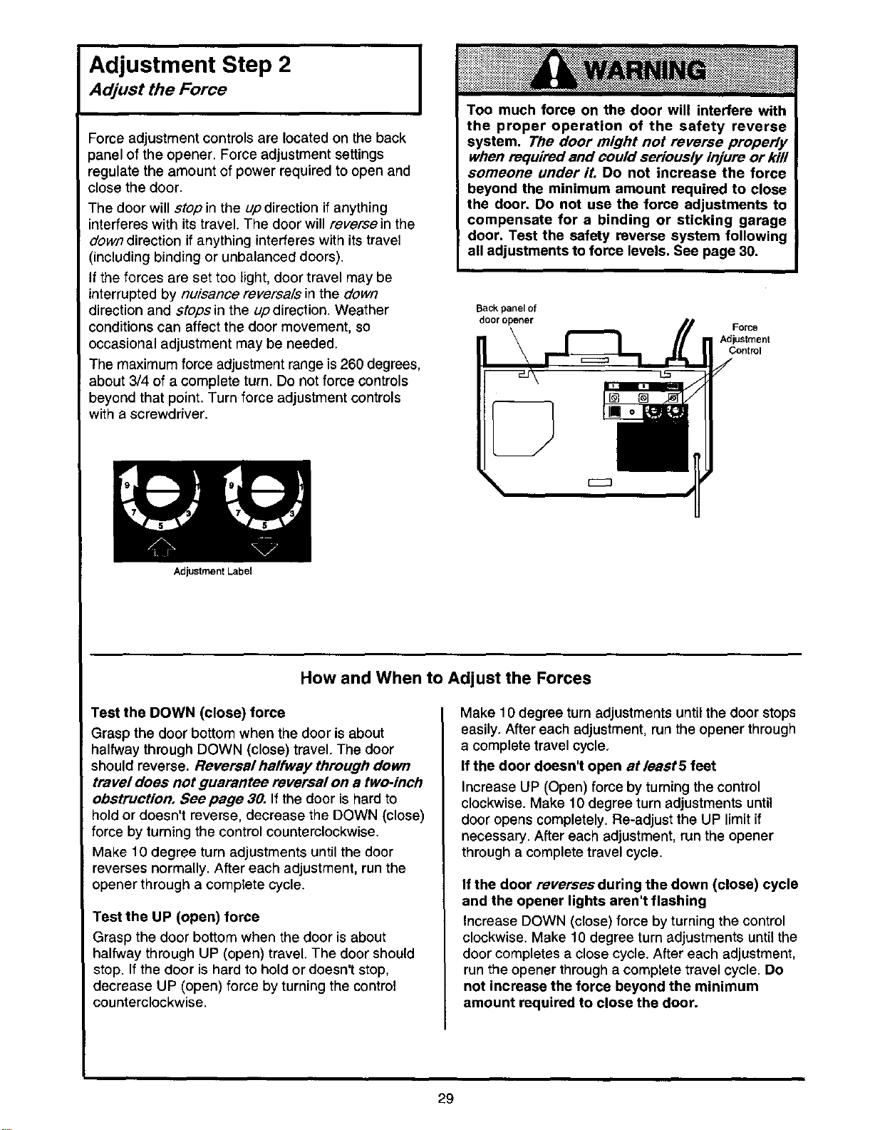
Adjustment Step 2
Adjust the Force
Force adjustment controls are located on the back
_anel of the opener. Force adjustment settings
regulate the amount of power required to open and
close the door.
The door will stop in the up direction if anything
interferes with its travel. The door will reversein the
down direction if anything interferes with its travel
(including binding or unbalanced doors).
If the forces are set too light, door travel may be
interrupted by nuisance reversals in the down
direction and stopsin the updirection. Weather
conditions can affect the door movement, so
occasional adjustment may be needed.
The maximum force adjustment range is 260 degrees,
about 3/4 of a complete turn. Do not force controls
beyond that point. Turn force adjustment controls
with a screwdriver.
Adjustment Label
Too much force on the door will interfere with
the proper operation of the safety reverse
system. The door might not reverse properly
when required and could seriously injure or kill
someone under it. Do not increase the force
beyond the minimum amount required to close
the door. Do not use the force adjustments to
compensate for a binding or sticking garage
door. Test the safety reverse system following
all adjustments to force levels. See page 30.
Back panel of
door opener
Force
Adjustment
Control
How and When to Adjust the Forces
Test the DOWN (close) force
Grasp the door bottom when the door is about
halfway through DOWN (close) travel. The door
should reverse. Reversal halfway through down
travel does not guarantee reversal on a two-inch
obstruction. See page 30. If the door is hard to
hold or doesn't reverse, decrease the DOWN (close)
force by turning the control counterclockwise.
Make 10 degree turn adjustments until the door
reverses normally. After each adjustment, run the
opener through a complete cycle.
Test the UP (open) force
Grasp the door bottom when the door is about
halfway through UP (open) travel. The door should
stop. If the door is hard to hold or doesn't stop,
decrease UP (open) force by turning the control
counterclockwise.
Make 10 degree turn adjustments until the door stops
easily. After each adjustment, run the opener through
a complete travel cycle.
If the door doesn't open atleast5 feet
Increase UP (Open) force by turning the control
clockwise. Make 10 degree turn adjustments until
door opens completely. Re-adjust the UP limitif
necessary. After each adjustment, run the opener
through a complete travel cycle.
If the door reverses during the down (close) cycle
and the opener lights aren't flashing
Increase DOWN (close) force by turning the control
clockwise. Make 10 degree turn adjustments until the
door completes a close cycle. After each adjustment,
run the opener through a complete travel cycle. Do
not increase the force beyond the minimum
amount required to close the door.
29
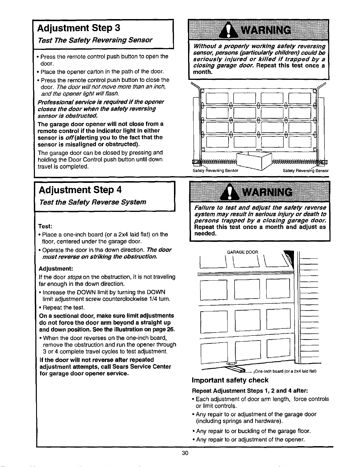
Adjustment Step 3
Test The Safety Reversing Sensor
• Press the remote control push button to open the
door.
• Place the opener carton in the path of the door.
• Press the remote control push button to close the
door. The door will not move more than an inch,
and the opener light will flash.
Professional service is required if the opener
closes the door when the safety reversing
sensor is obstructed,
The garage door opener will not close from a
remote control if the indicator light in either
sensor is off(alerting you to the fact that the
sensor is misaligned or obstructed),
The garage door can be closed by pressing and
holding the Door Control push button until down
travel iscompleted,
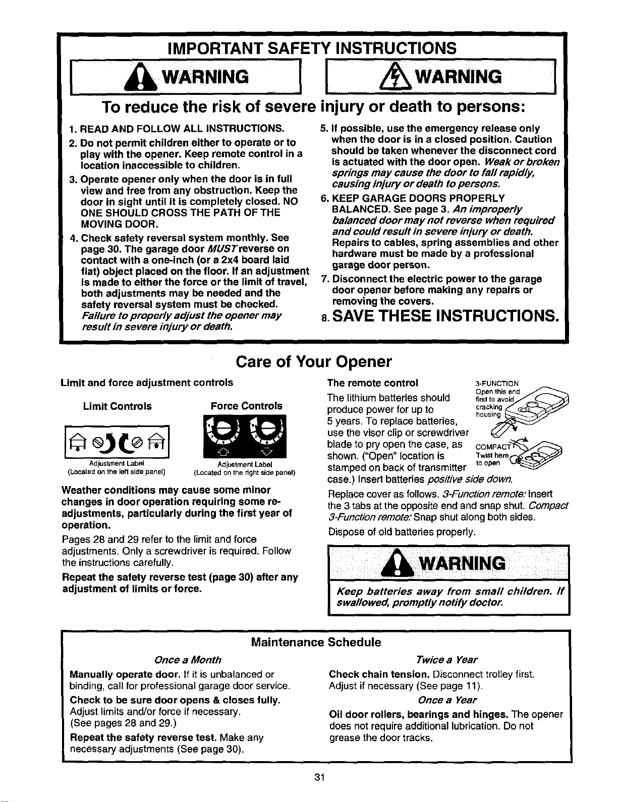
Adjustment Step 4
Test the Safety Reverse System
Test:
• Place a one-inch board (or a 2x4 laid flat) on the
floor, centered under the garage door.
• Operate the door in the down direction. The door
must reverse on striking the obstruction,
I Adjustment:
If the door stopson the obstruction, it is not traveling
far enough in the down direction.
• Increase the DOWN limitby turning the DOWN
limitadjustment screw countemlockwise 1/4 turn.
• Repeat the test.
On a sectional door, make sure limit adjustments
do not force the door arm beyond a straight up
and down position. See the illustration on page 26.
• When the door reverses on the one-inch board,
remove the obstruction and run the opener through
3 or 4 complete travel cycles to test adjustment.
Ifthe door will not reverse after repeated
adjustment attempts, call Sears Service Center
for garage door opener service.
t i
oard (or a 2x4 laid flat)
Important safety check
Repeat Adjustment Steps 1, 2 and 4 after:
• Each adjustment ofdoor arm length, force controls
or limit controls.
• Any repair to or adjustment of the garage door
(including springs and hardware).
• Any repair to or buckling of the garage floor.
• Any repair to or adjustment of the opener.
3O
IMPORTANT SAFETY INSTRUCTIONS
I WARN,NG[I WARN,NG
To reduce the risk of severe injury or death to persons:
[
1. READ AND FOLLOW ALL INSTRUCTIONS.
2. Do not permit children either to operate or to
play with the opener. Keep remote control in a
location inaccessible to children.
3. Operate opener only when the door is in full
view and free from any obstruction. Keep the
door in sight until it is completely closed. NO
ONE SHOULD CROSS THE PATH OF THE
MOVING DOOR.
4. Check safety reversal system monthly. See
page 30. The garage door MUSTreverse on
contact with a one-inch (or a 2x4 board laid
flat) object placed on the floor. If an adjustment
is made to either the force or the limit of travel,
both adjustments may be needed and the
safety reversal system must be checked.
Failure to properly adjust the opener may
result in severe injury or death,
5. If possible, use the emergency release only
when the door is in a closed position. Caution
should be taken whenever the disconnect cord
is actuated with the door open. Weak or broken
springs may cause the door to fall rapidly,
causing injury or death to persons.
6. KEEP GARAGE DOORS PROPERLY
BALANCED. See page 3. An improperly
balanced door may not reverse when required
and could result in severe injury or death.
Repairs to cables, spring assemblies and other
hardware must be made by a professional
garage door person.
7. Disconnect the electric power to the garage
door opener before making any repairs or
removing the covers.
8.SAVE THESE INSTRUCTIONS.
Care of Your Opener
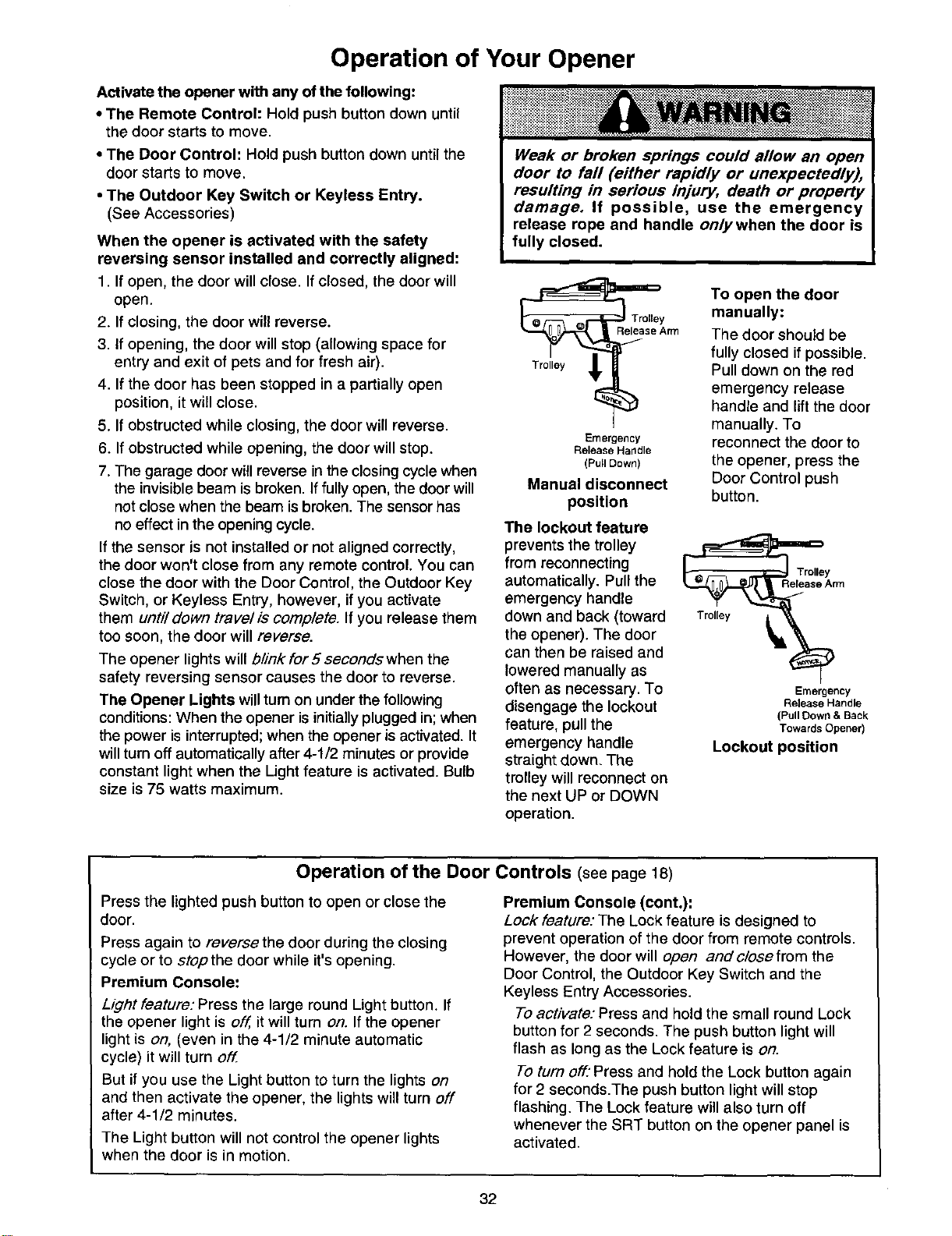
Limit and force adjustment controls
Limit Controls
Adjustment Label
(Located on the left side panel)
Force Controls
AdjustmentLabel
(Locatedonthe rightsidepanel)
Weather conditions may cause some minor
changes in door operation requiring some re-
adjustments, particularly during the first year of
operation.
Pages 28 and 29 refer to the limitand force
adjustments. Only a screwdriver is required. Follow
the instructions carefully.
Repeat the safety reverse test (page 30) after any
adjustment of limits or force.
The remote control
The lithiumbatteries should
produce power for up to
5 years. To replace batteries,
use the visor clip or screwdriver
blade to pry open the case, as
shown. ("Open" location is
stamped on back of transmitter
3-FUNCTION
Open this end
first to avoid
cracking
COMPAC'_
Twist here
to open
case.) Insert batteries positive side down.
Replace cover as follows. 3-Function remote." Insert
the 3 tabs at the opposite end and snap shut. Compact
3-Function remote: Snap shut along both sides.
Dispose of old batteries properly.
Maintenance Schedule
Once a Month
Manually operate door. If it is unbalanced or
binding, call for professional garage door service.
Check to be sure door opens & closes fully.
Adjust limits and/or force if necessary.
(See pages 28 and 29.)
Repeat the safety reverse test, Make any
necessary adjustments (See page 30).
I
Twice a Year
Check chain tension. Disconnect trolley first.
Adjust if necessary (See page 11).
Once a Year
Oil door rollers, bearings and hinges. The opener
does not require additional lubrication. Do not
grease the door tracks.
31
Operation of Your Opener
Activate the opener with any of the following:
• The Remote Control: Hold push button down until
the door starts to move.
• The Door Control: Hold push button down until the
door starts to move.
• The Outdoor Key Switch or Keyless Entry.
(See Accessories)
When the opener is activated with the safety
reversing sensor installed and correctly aligned:
1. If open, the door will close. If closed, the door will
open.
2. If closing, the door will reverse.
3. If opening, the door will stop (allowing space for
entry and exit of pets and for fresh air).
4. If the door has been stopped in a partially open
position, it willclose.
5. If obstructed while closing, the door will reverse.
6. If obstructed while opening, the door will stop.
7. The garage door willreverse in the closing cycle when
the invisible beam is broken. If fully open, the door will
not close when the beam is broken. The sensor has
no effect in the opening cycle.
If the sensor is not installed or not aligned correctly,
the door won't close from any remote control. You can
close the door with the Door Control, the Outdoor Key
Switch, or Keyless Entry, however, if you activate
them unti/down travel is complete. If you release them
too SOOn,the door will reverse.
The opener lights will b/ink for 5 seconds when the
safety reversing sensor causes the door to reverse.
The Opener Lights will turn on under the following
conditions: When the opener is initially plugged in; when
the power is interrupted; when the opener is activated. It
will turn off automatically after 4-1/2 minutes or provide
constant light when the Light feature is activated. Bulb
size is 75 watts maximum.
Weak or broken springs could allow an open
door to fall (either rapidly or unexpectedly),
resulting in serious injury, death or property
damage. If possible, use the emergency
release rope and handle onlywhen the door is
fully closed.
rm
Emergency
Release Handle
(Pull Down)
Manual disconnect
position
The lockout feature
prevents the trolley
from reconnecting
automatically. Pull the
emergency handle
down and back (toward
the opener). The door
can then be raised and
lowered manually as
often as necessary. To
disengage the lockout
feature, pull the
emergency handle
straight down. The
trolley will reconnect on
the next UP or DOWN
To open the door
manually:
The door should be
fully closed ifpossible.
Pull clown on the red
emergency release
handle and lift the door
manually, To
reconnect the door to
the opener, press the
Door Control push
button.
Emergency
Release Handle
(Pull Down & Back
Towards Opener)
Lockout position
operation.
Operation of the Door Controls (seepage18)
Press the lighted push button to open or close the
door.
Press again to reversethe door during the closing
cycle or to stop the door while it's opening,
Premium Console:
Light feature: Press the large round Light button. If
the opener light is off, it will turn on. If the opener
light is on, (even in the 4-1/2 minute automatic
cycle) it will turn off.
But if you use the Light button to turn the lights on
and then activate the opener, the lights will turn off
after 4-1/2 minutes.
The Light button will not control the opener lights
when the door is in motion.
Premium Console (cont.):
Lock feature: The Lock feature is designed to
prevent operation of the door from remote controls.
However, the door will open andc/osefrom the
Door Control, the Outdoor Key Switch and the
Keyless Entry Accessories.
To activate: Press and hold the small round Lock
button for 2 seconds. The push button light will
flash as long as the Lock feature is on.
To turn off."Press and hold the Lock button again
for 2 seconds.The push button lightwill stop
flashing. The Lock feature will also turn off
whenever the SRT button on the opener panel is
activated.
32
Receiver and Remote Control Programming
To comply with FCC rules, adjustment or modifications of this
receiver and/or transmitter are prohibited, except for changing
the code setting or replacing the battery. THERE ARE NO
OTHER USER SERVICEABLE PARTS.
Models with 3-function remote controls: The
remote control(s) has been factory set to operate
with the large push button. However, you can use
either of the two small buttons, ifyou prefer. And,
the 3-function remote control(s) can also activate
additional garage door openers and/or light controls.
Below are instructionsfor programming your opener
to match the other buttons on your remote controls
and any additional remote controls you may
purchase. See available accessories on page 38.
Children operating or playing with a garage
door opener can injure themselves or others.
The garage door could close and cause
serious injury or death. Do not allow children
to operate the door push button(s) or remote
control(s).
A moving garage door could injure or kill
someone under it. Activate the opener only
when you can see the door clearly, it is free of
obstructions, and is properly adjusted.
53000SRT Series Garage Door Openers
(With "SRT" Button)
Your "SRT" garage door opener will operate with as
many as four "SRT" portable remote controlsand
one Multi-Function Keyless Entry.
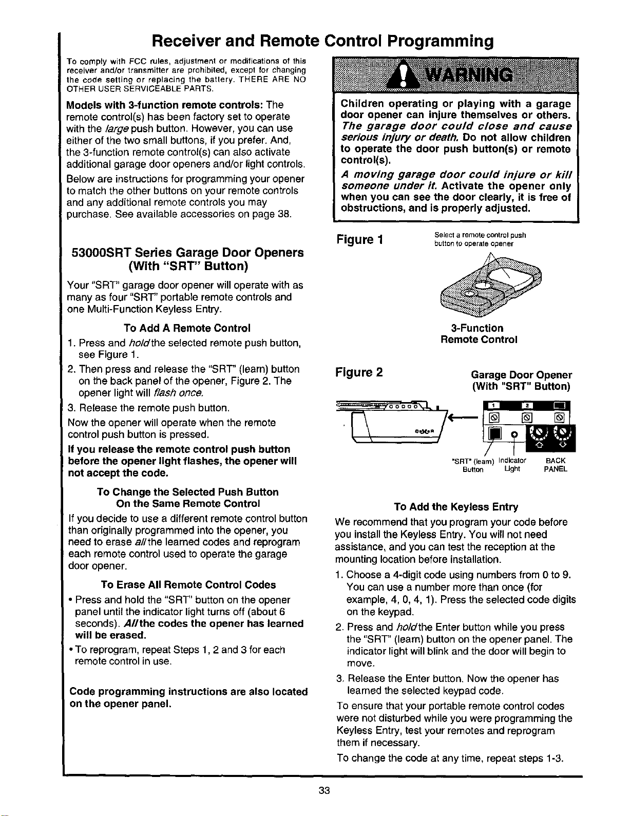
To Add A Remote Control
• Press and ho/dthe selected remote push button,
see Figure 1.
2. Then press and release the "SRT" (learn) button
on the back panel of the opener, Figure 2. The
opener light will flash once.
! 3. Release the remote push button.
Now the opener will operate when the remote
control push button is pressed.
If you release the remote control push button
before the opener light flashes, the opener will
not accept the code.
To Change the Selected Push Button
On the Same Remote Control
If you decide to use a different remote control button
than originally programmed into the opener, you
need to erase allthe learned codes and reprogram
each remote control used to operate the garage
door opener.
To Erase All Remote Control Codes
• Press and hold the "SRT" button on the opener
panel until the indicator light turns off (about 6
seconds). AIIthe codes the opener has learned
will be erased.
• To reprogram, repeat Steps 1,2 and 3 for each
remote control in use.
Code programming instructions are also located
on the opener panel.
Figure I
Select a remote control push
button to operate opener
3-Function
Remote Control
Figure 2
Garage Door Opener
(With "SRT" Button)
"SRT" (learn) Indicator BACK
Button Ught PANEL
To Add the Keyless Entry
We recommend that you program your code before
you install the Keyless Entry. You will not need
assistance, and you can test the reception at the
mounting location before installation.
1. Choose a 4-digit code using numbers from 0 to 9.
You can use a number more than once (for
example, 4, 0, 4, 1). Press the selected code digits
on the keypad.
2. Press and holdthe Enter button while you press
the "SRT' (learn) button on the opener panel. The
indicator lightwill blink and the door will begin to
move,
3. Release the Enter button. Now the opener has
learned the selected keypad code.
To ensure that your portable remote control codes
were not disturbed while you were programming the
Keyless Entry, test your remotes and reprogram
them if necessary.
To change the code at any time, repeat steps 1-3.
33
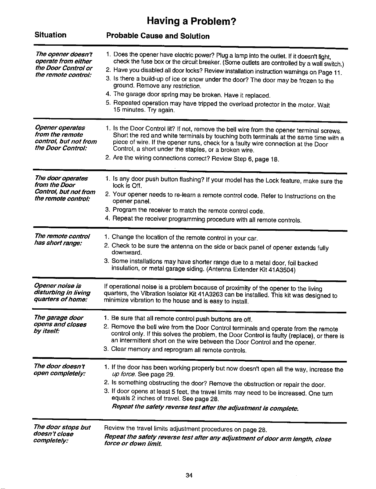
Situation
Having a Problem?
Probable Cause and Solution
The opener doesn't
operate from either
the Doer Control or
the remote control:
1. Does the opener have electric power?. Pluga lamp into the outlet. If itdoesn't light,
check the fuse box or the circuit breaker. (Some outlets are controlled by a wall switch.)
2. Have you disabled all door locks? Review installation instruction warnings on Page 11.
3. is there a build-up of ice or snow under the door? The door may be frozen to the
ground. Remove any restriction.
4. The garage door spring may be broken. Have it replaced.
5. Repeated operation may have tripped the overload protector in the motor. Wait
15 minutes. Try again.
Opener operates
from the remote
control, but not from
the Door Control:
1. Is the Door Control lit? If not, remove the bell wire from the opener terminal screws.
Short the red and white terminals by touching both terminals at the same time with a
piece of wire. If the opener runs, check for a faulty wire connection at the Door
Control, a short under the staples, or a broken wire.
2. Are the wiring connections correct? Review Step 6, page 18.
The door operates
from the Door
Control, but not from
the remote control:
1. Is any door push button flashing? If your model has the Lock feature, make sure the
lock is Off.
2. Your opener needs to re-learn a remote control code. Refer to instructions on the
opener panel.
3, Program the receiver to match the remote control code,
4. Repeat the receiver programming procedure with all remote controls.
The remote control
has short range:
1. Change the location of the remote control in your car.
2. Check to be sure the antenna on the side or back panel of opener extends fully
downward.
,
Some installations may have shorter range due to a metal door, foil backed
insulation, or metal garage siding. (Antenna Extender Kit 41A3504)
Opener noise is
disturbing in living
quarters of home:
If operational noise is a problem because of proximityof the opener to the living
quarters, the Vibration Isolator Kit 41A3263 can be installed. This kit was designed to
minimize vibration to the house and is easy to install.
The garage door
opens and closes
by itself:
1. Be sure that all remote control push buttons are off.
2. Remove the bell wire from the Door Control terminals and operate from the remote
control only. If this solves the problem, the Door Control is faulty (replace), or there is
an intermittent short on the wire between the Door Control and the opener.
3. Clear memory and reprogram all remote controls.
The door doesn't
open completely:
1. If the door has been working properly but now doesn't open all the way, increase the
up force. See page 29.
2. Is something obstructing the door? Remove the obstruction or repair the doer.
3. If door opens at least 5 feet, the travel limits may need to be increased. One turn
equals 2 inches of travel. See page 28.
Repeat the safety reverse test after the adjustment is complete.
The door stops but
doesn ?close
completely:
Review the travel limits adjustment procedures on page 28.
Repeat the safety reverse test after any adjustment of door arm length, close
force or down limit,
34
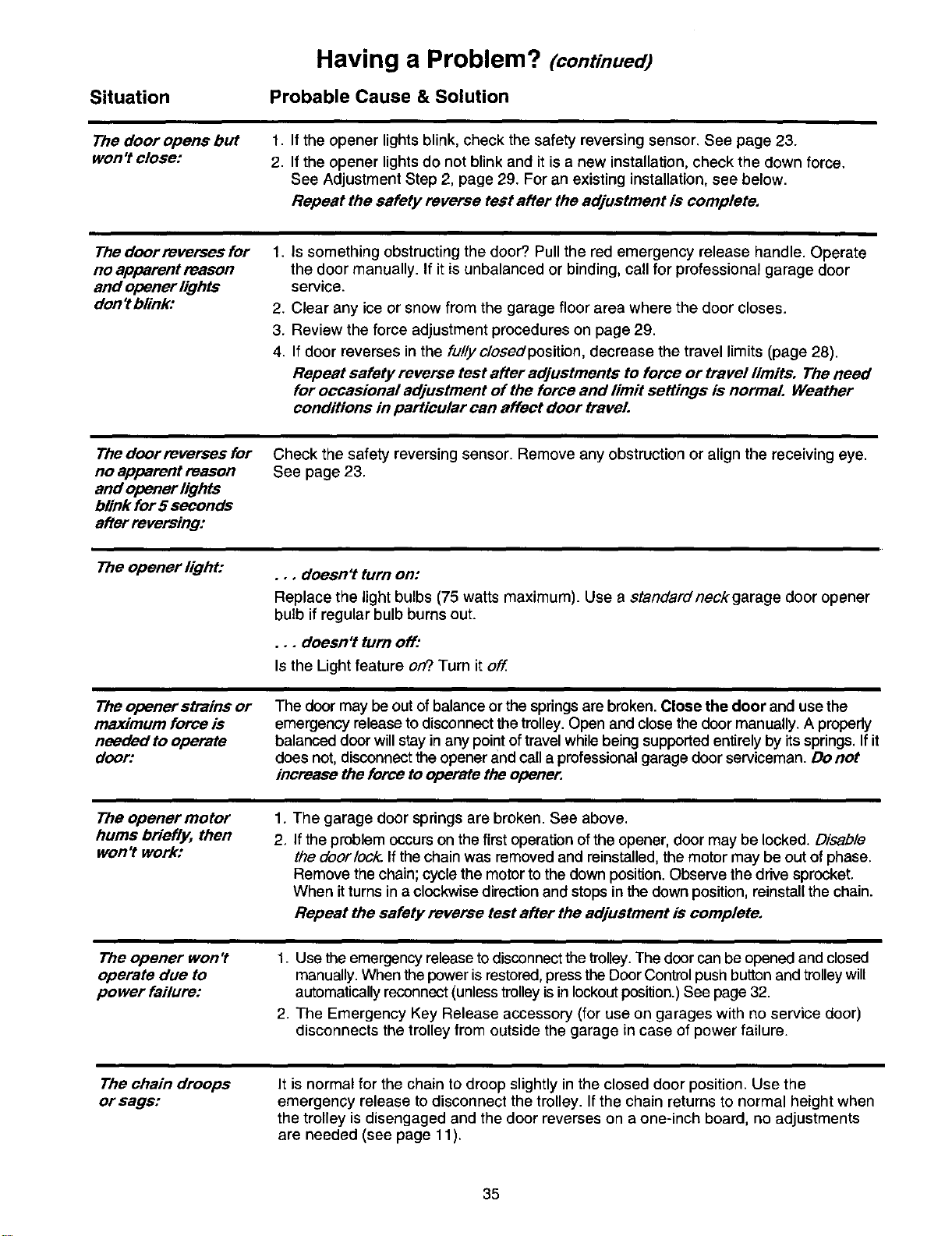
Situation
Having a Problem? (continued)
Probable Cause & Solution
The door opens but 1,
won't close: 2,
If the opener lights blink, check the safety reversing sensor. See page 23.
If the opener lights do not blink and it is a new installation, check the down force.
See Adjustment Step 2, page 29. For an existing installation, see below.
Repeat the safety reverse test after the adjustment is complete,
The door reverses for
no apparent reason
and opener lights
don't blink:
1. Is something obstructing the door? Pull the red emergency release handle. Operate
the door manually. If it is unbalanced or binding, call for professional garage door
service.
2.
3.
4.
Clear any ice or snow from the garage floor area where the door closes.
Review the force adjustment procedures on page 29.
If door reverses in the fully closedposition, decrease the travel limits (page 28).
Repeat safety reverse test after adjustments to force or travel limits, The need
for occasional adjustment of the force and limit seffings is normal Weather
conditions in particular can affect door traveL
The door reverses for
no apparent reason
and opener lights
blink for 5 seconds
after reversing:
Check the safety reversing sensor. Remove any obstruction or align the receiving eye.
See page 23.
The opener light:
The opener strains or
maximum force is
needed to operate
door:
•., doesn't turn on:
Replace the light bulbs (75 watts maximum). Use a standard neck garage door opener
bulb if regular bulb burns out.
•.. doesn't turn off:
Is the Light feature on?.Turn it off
The door may be out ofbalance or the springsare broken. Close the door and use the
emergency release to disconnectthe trolley.Open and close the doormanually. A properly
balanced door willstay in any pointoftravel whilebeing supportedentirely by itssprings. Ifit
does not,disconnectthe opener and call a professionalgarage door serviceman. Do not
increase the force to operate the opener,
The opener motor
hums briefly, then
won't work:
1.
2,
The garage door springs are broken. See above.
if the problem occurs on the first operation of the opener, door may be locked. Disable
the doorlock. Ifthe chain was removed and reinstalled, the motor may be out of phase.
Remove the chain; cycle the motor to the down position. Observe the drive sprocket.
When it turns in a clockwise direction and stops in the down position, reinstall the chain.
Repeat the safety reverse test after the adjustment is complete,
The opener won't
operate due to
power failure:
1. Use the emergency release to disconnectthe troUey.The doorcan be opened and closed
manually. When the power is restored, press the Door Control push button and trolley will
automatically reconnect (unless trolley is in lockout position.)See page 32.
2. The Emergency Key Release accessory (for use on garages with no service door)
disconnects the trolley from outside the garage in case of power failure.
The chain droops
or sags:
It is normal for the chain to droop slightly in the closed door position. Use the
emergency release to disconnect the trolley. If the chain returns to normal height when
the trolley is disengaged and the door reverses on a one-inch board, no adjustments
are needed (see page 11).
35
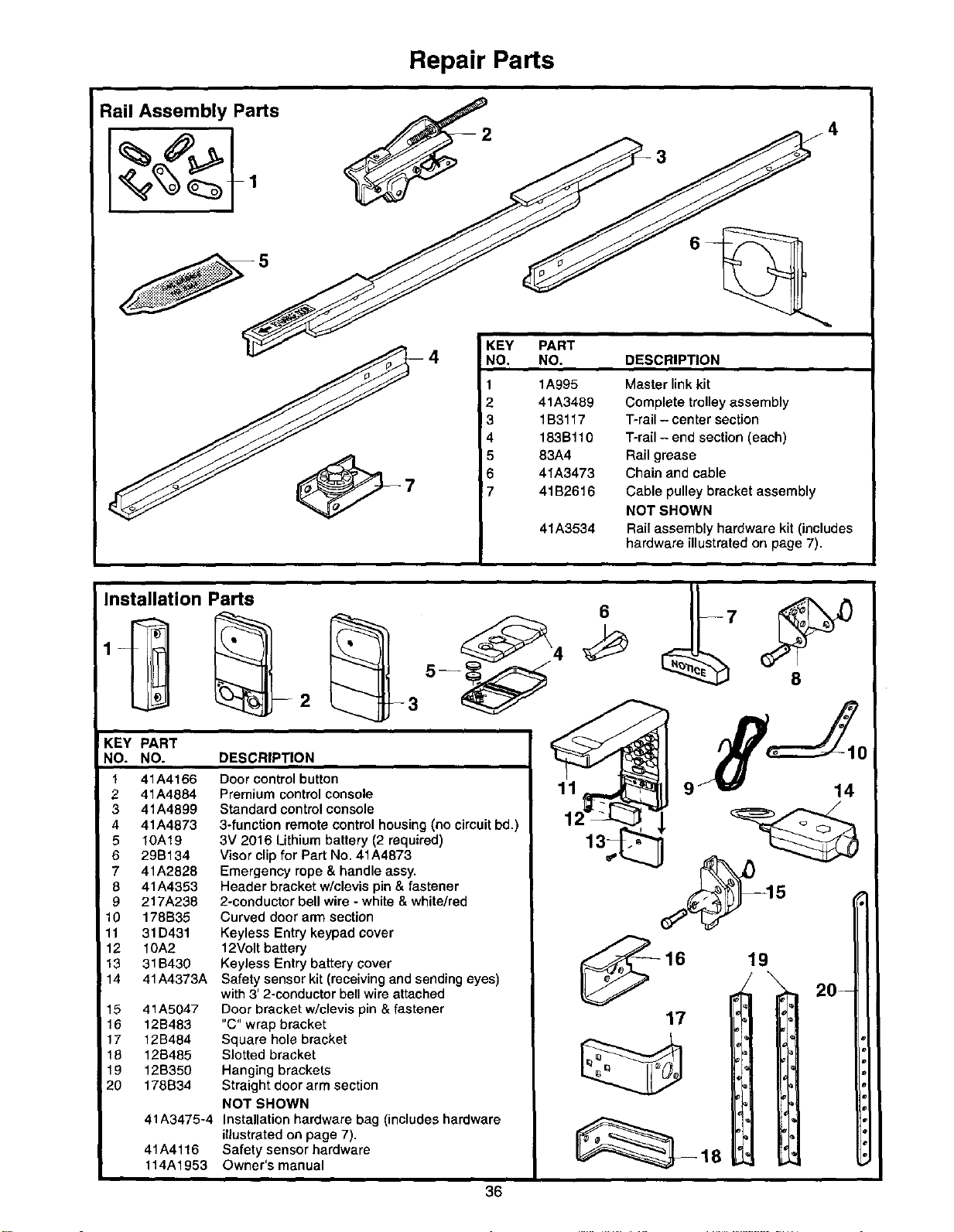
Repair Parts
Rail Assembly Parts
4 NK_Y PART DESCRIPT,ON
1A995
2 41A3489
!3 1B3117
4 183Bl10
83A4
41A3473
41B2616
41A3534
Master link kit
Complete trolley assembly
T-rail - center section
T-rail - end section (each)
Rail grease
Chain and cable
Cable pulley bracket assembly
NOT SHOWN
Rail assembly hardware kit (includes
hardware illustrated on page 7).
Installation Parts
!KEY PART
NO. NO. DESCRIPTION
1 41A4166
2 41A4884
3 41A4899
4 41A4873
5 10A19
6 29B134
7 41A2828
8 41A4353
9 217A238
10 178B35
11 31D431
12 10A2
13 31B430
14 41A4373A
15 41A5047
16 12B483
17 12B484
18 12S485
19 12B350
20 178B34
41A3475-4
41A4116
114A1953
Door control button
Premium control console
Standard control console
3-function remote control housing (no circuit bd.)
3V 2016 Lithium battery (2 required)
Visor clip for Part No. 41A4873
Emergency rope & handle assy.
Header bracket w/clevis pin & fastener
2-conductor bell wire - white & white/red
Curved door arm section
Keyless Entry keypad cover
12Volt battery
Keyless Entry battery cover
Safety sensor kit (receiving and sending eyes)
with 3' 2-conductor bell wire attached
Door bracket w/clevis pin & fastener
"C" wrap bracket
Square hole bracket
Slotted bracket
Hanging brackets
Straight doer arm section
NOT SHOWN
Installation hardware bag (includes hardware
illustrated on page 7).
Safety sensor hardware
Owner's manual
36
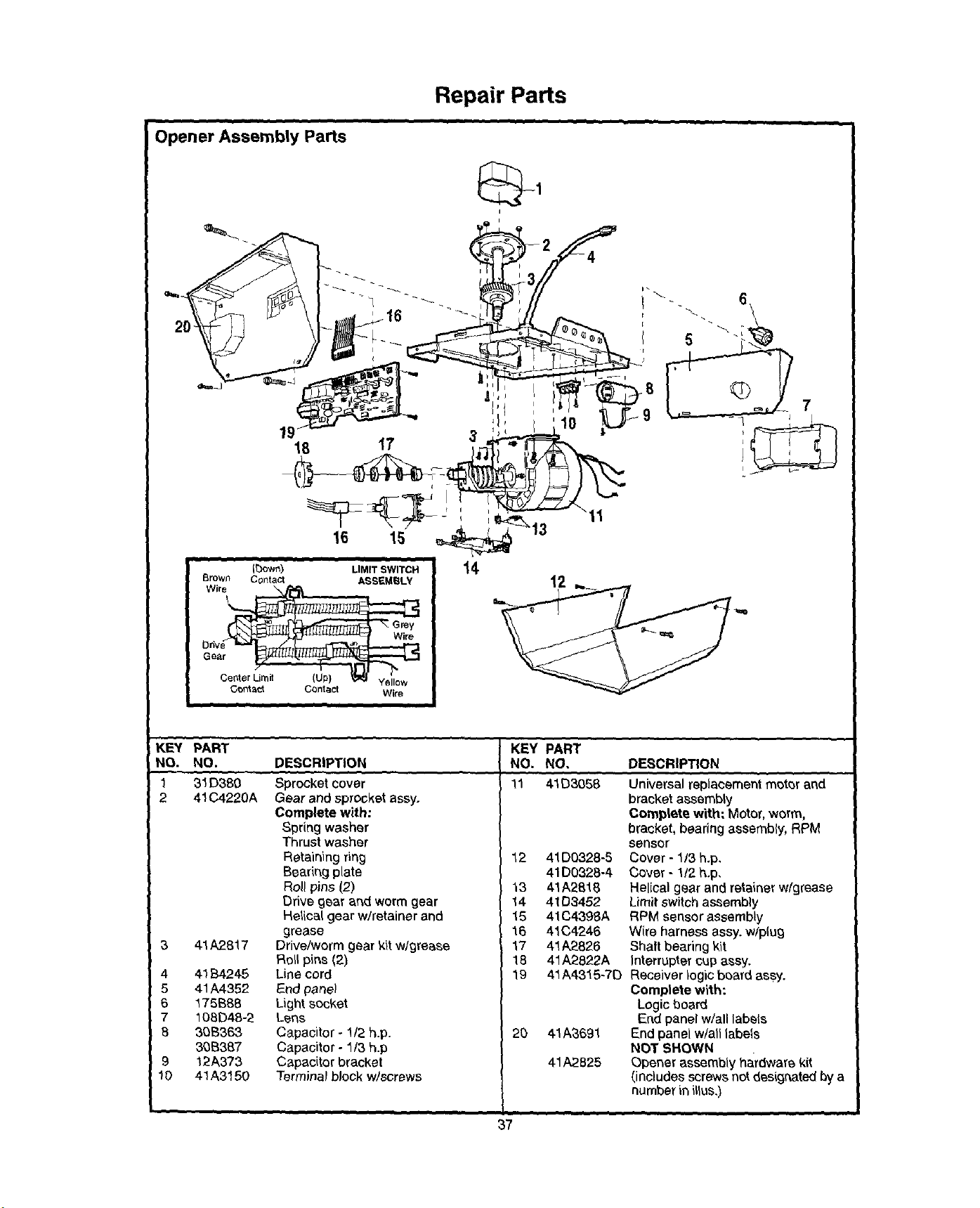
Repair Parts
i i i = i • • , , .
Opener Assembly Parts
I
t
16 _15 _' 13
(bowr_) LIMIT SWITCH
Brown Contact ASSEMBLY
Grey
I Drive Wire
I Gear /
I G_t_t Contact Wire
I
i i i
14
KEY PART
NO. NO.
1 31 [3380
2 41C4220A
3 41A2817
4 41B4245
5 41,4,4352
6 175B6B
7 108D48-2
B 30B363
3_B387
9 12A373
10 41A3150
DESCRIPTION
Sprocket cover
Gear and sprocket assy.
Complete with:
Spring washer
Thrust washer
Retaining ring
Bearing plate
Rol! pins (2)
Drive gear and worm gear
Helical gear w/retainer and
grease
Drive/worm gear kit w/grease
Roll pins {2)
Line cord
End panel
Light socket
Lens
Capacitor - 1/2 h.p.
Capacitor - 1/3 h.p
Capacitor bracket
Terminalblock w/screws
• , , ,,,,
KEY PART
NO. NO.
11 41D3058
12 41D0328-5
41D0328-4
13 41A2816
14 41D3452
15 41CZ139BA
16 41C4246
17 41A2826
18 41A2822A
19 41A43"15-7D
2D 41A_,691
41A2825
DESCRIPTION
Universalreplacement motor and
bracket assembly
Complete with: Motor,worm,
bracket, bearing assembly, RPM
sensor
Cover - 1/3 h.p,
Cover - 1/2 h.p,
Helical gear and retainer wfgrease
Limitswitch assembly
RPM sensor assembly
W{re harnessassy. w/plug
Shaft bearing kit
Interrapter cup assy.
Receiver logic board assy.
Complete with:
Logicboard
End panelw/all labels
End panel w/alllabels
NOT SHOWN
Opener assembly hardware kit
(includes screws not desigrlated by a
number in illus,)
...... i i i i • •
37
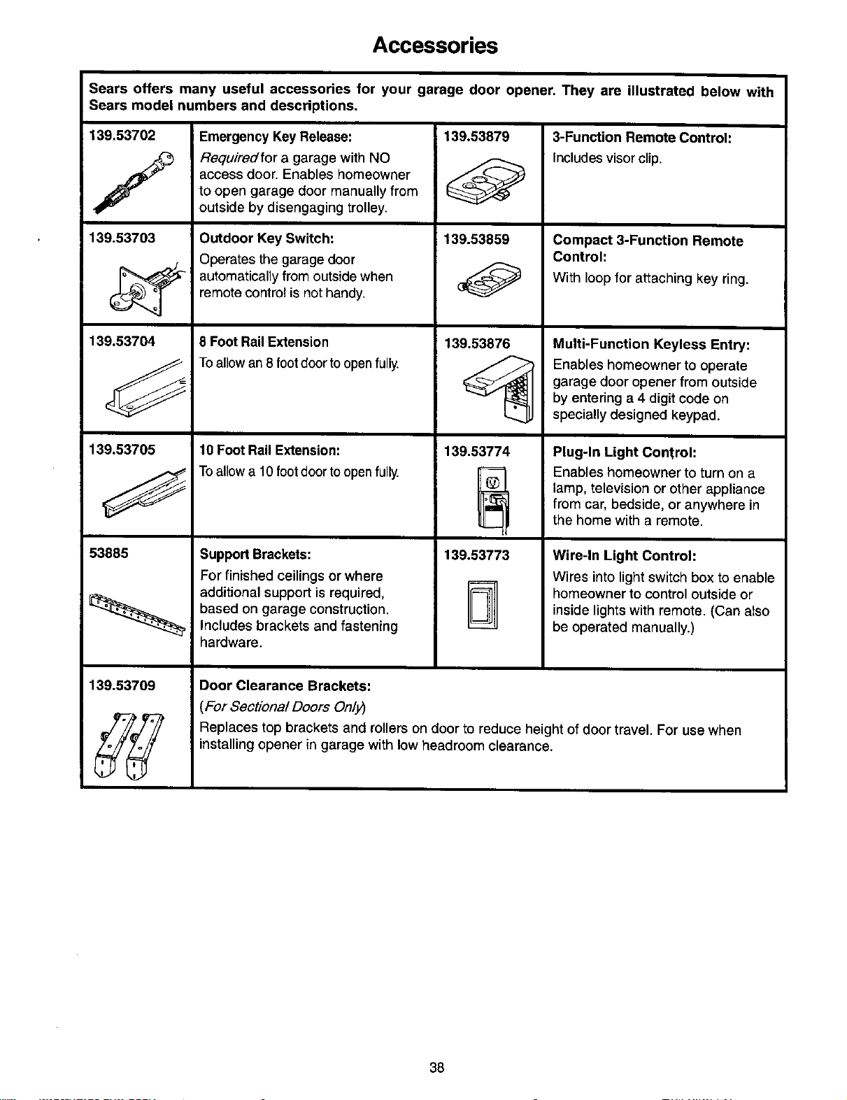
Accessories
Sears offers many useful accessories for your garage door opener. They are illustrated below with
Sears model numbers and descriptions.
3-Function Remote Control:
Includes visor clip.
139.53702
f
139.53703
139.53704
139.53705
53885
139.53709
Emergency Key Release:
Requiredfor a garage with NO
access door. Enables homeowner
to open garage door manually from
outside by disengaging trolley.
Outdoor Key Switch:
Operates the garage door
automatically from outside when
remote control is not handy.
8 Foot Rail Extension
Toallow an 8 footdoor toopen fully,
10 Foot Rail Extension:
Toallow a 10 foot door to open fully.
Support Brackets:
For finished ceilings or where
additional support is required,
based on garage construction.
Includes brackets and fastening
hardware.
139.53879
139.53859
139.53876
139.53774
@
139.53773
Compact 3-Function Remote
Control:
With loop for attaching key ring.
Multi-Function Keyless Entry:
Enables homeowner to operate
garage door opener from outside
by entering a 4 digit code on
specially designed keypad.
Plug-In Light Control:
Enables homeowner to turn on a
lamp, television or other appliance
from car, bedside, or anywhere in
the home with a remote.
Wire-In Light Control:
Wires into light switch box to enable
homeowner to control outside or
inside lights with remote. (Can also
be operated manually.)
Door Clearance Brackets:
(For Sectional Doors Onlj_
Replaces top brackets and rollers on door to reduce height of door travel. For use when
installing opener in garage with low headroom clearance.
38

Index
Access Door/Outside Key Release Accessory ............................................................................................... 4, 5
Chain Tension .............................................................................................................................................. 4, 5, 11
Electrical Safety Warnings ........................................................................................................................ 2, 20, 31
Garage Door
Testing for balance, binding and sticking ................................................................................................... 3, 28, 31
Determining high point of travel:
Sectional door ................................................................................................................................................... 12
One-piece door ................................................................................................................................................. 13
Disabling existing locks.................................................................................................................................... 3, 11
Door clearance brackets (for garages with low headroom) ........................................................................... 12, 38
Fome controls
Adjustment procedures ................................................................................................................................. 4, 29
Problems that might require force adjustments .......................................................................................... 34, 35
Safety warnings .......................................................................................................................................... 29, 31
Door hardware ..................................................................................................................... 3, 9, 11, 12, 18, 31,32
Maintenance instruction label ........................................................................................................................ 11,28
Reinforcement requirements ........................................................................................................................... 4, 24
Removing of all ropes ....................................................................................................................................... 3, 11
Possible door damage ................................................................................................................................... 16, 24
Travel limits
Adjustment procedures ..................................................................................................................................... 28
Problems that might require limit adjustments ............................................................................................ 34, 35
Safety warnings .......................................................................................................................................... 28, 31
Manual (Emergency) Release Rope & Handle
Lockout feature .................................................................................................................................................... 32
Manual disconnect ............................................................................................................................................... 32
Safety warnings ................................................................................................................................. 11, 19, 31, 32
Opener Terminals
Door control connections ..................................................................................................................................... 18
Safety reversing sensor connections ................................................................................................................... 23
Operational Noise
Sprocket noise ..................................................................................................................................................... 11
Vibration noise (isolator kit) ................................................................................................................................. 34
Receiver and Remote Control
Programming the receiver ................................................................................................................................... 33
Erasing all codes ................................................................................................................................................. 33
Activating other openers ...................................................................................................................................... 33
Safety warning ..................................................................................................................................................... 33
Problems with remote control operation .............................................................................................................. 34
Safety Reverse Test Procedure .......................................................................................................................... 30
Testing required ................................................................................................................................. t t, 30, 34, 35
Safety reverse system problems
Securing header bracket to wall ....................................................................................................................... 12
Adjusting travel limits ........................................................................................................................................ 28
Applying excessive force on the door ............................................................................................................... 29
Buckling or uneven floor ................................................................................................................................. 4, 5
Safety Warnings ......................................................... 2, 3, 9, 11, 12, 16, 18, 19, 20, 21,24, 28, 29, 30, 31, 32, 33
User Instruction Label for garage wall ........................................................................................................ 11, 18
39

Forprofessionalinstallation
Call 24 hours a day, 7 days a week
1-800-865-8500
For the repair or replacement parts you need
Call 7 am - 7 pm, 7 days a week
1-800-366-PART
(1-800-366-7278)
For in-home major brand repair service
Call 24 hours a day, 7 days a week
1-800-4-REPAIR
(1-800-473-7247)
For the location of a Sears Repair Service Center in your area
Call 24 hours a day, 7 days a week
1-800-488-1222
For information on purchasing a Sears Maintenance Agreement or to inquire
about an existing Agreement
Call 9 am - 5 pm, Monday-Saturday
1-800-827-6655
The model number label is located under the light lens on the front end
panel of your opener. When requesting service or ordering parts, always
give the following information:
• Product Type
• Model Number
• Part Number
• Part Description
SEARS
America's Repair Specialists
SEARS WARRANTY
FULL 90oDAY WARRANTY ON GARAGE DOOR OPENER
For 90 days from the date of purchase, Sears will repair this Garage Door Opener, free of charge, if defective in material or workmanship.
LIMITED WARRANTY
From the 91st day until one year from the date of purchase, Sears will furnish replacement parts for any defective parts, free of charge.
You pay for labor,
LIMITED WARRANTY ON MOTOR
1/2Hp MOTOR: After I year and through 5 years, if the motor on this Garage Door Opener is defective, Sears will furnish a replacement
motor, free of charge, You pay for labor.
1/3HP MOTOR: After 1 year and through 3 years, ifthe motor on this Garage Door Opener is defective, Sears will furnish a replacement
motor, free of charge. You pay for labor.
LIMITATION ON LIABILITY
SEARS WILL NOT BE LIABLE FOR LOSS OR DAMAGE TO PROPERTY OR ANY INCIDENTAL OR CONSEQUENTIAL LOSS OR
EXPENSE FROM PROPERTY DAMAGE DUE DIRECTLY OR INDIRECTLY FROM THE USE OF THIS PRODUCT. Some states do
not allow the exclusion or limitation of incidental or consequential damages, so the above limitalion or exclusion may not apply to you,
This warranty does not cover light bulbs or repair parts necessary because of operator abuse or negligence, including the failure to
install, adjust and operate this garage door opener according to instructions contained in the owner's manual.
WARRANTY SERVICE IS AVAILABLE BY SIMPLY CONTACTING THE NEAREST SEARS CENTER/DEPARTMENT IN THE UNITED
STATES.
This warranty applies only while this product is in use in the United States.
This warranty gives you specific legal rights, and you may also have other rights which vary from state to state.
Sears, Roebuck and Co., Dept. 817WA, Hoffman Estates, IL 60179
5
114A1953G ©1998, All Rights Reserved Printed in Mexico