(Picture is only for reference , subject to the actual product)
(Picture is only for reference , subject to the actual product)
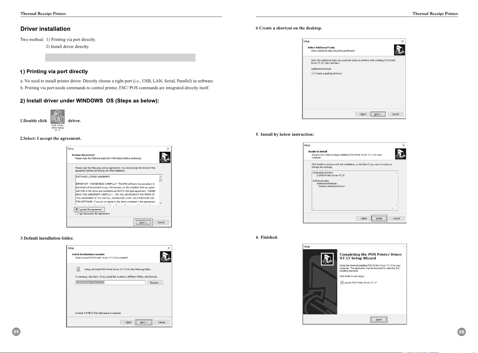
Windows Driver Download link:
http://bit.ly/PrinterDriver80mm
The drive has been installed successfully when test page is
printed. Thanks for your support
Installation Guide of MAC Driver
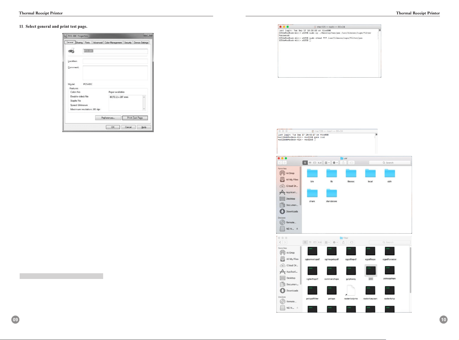
Driver in mac OS:pos,pos-80.ppd
pos driver is for 80mm printer,
Method of operation:
1.Copying the pos driver file to the specified directory.
Method1:
(1)Open the terminal to enter commands(command+blank or Find spotlight in the upper right
corner of the screen;
(2)Input“ter”and press“Enter”to open terminal. You may be asked to enter a password when
executing terminal commands,enter the password directly and then click enter):
sudo cp ./Desktop/mac/pos/usr/libexec/cups/filter/
This command copies the driver to the corresponding folder of the MAC OS.
If method 1 fails, use method 2 below.
Input command: sudo chmod 777 /usr/libexec/cups/filter/pos
This is to modify the permissions of the driver.(777 means readable,writable,and executable)
You can also find the corresponding file right-click display profile, copy the path to modify
permissions.
Method 2:
(1) First, Open the “Terminal” to enter commands(command+blank or Find spotlight in
the upper right corner of the screen,input “ter”and press Enter to open terminal:
Input “open /usr” Then find the Filter according to /usr/libexec/cups/filter/ Copy pos
driver into filter.
(2) Right-click the pos file and select show profile, Click on the lower right corner, Enter
password, modify permissions to read and write.
Note: if the above two methods are successful, "2. Input command" will be carried out. If not,
the terminal prompt message will be checked.
2. Select the corresponding PPD file,insert the printer into the MAC, select the corresponding
PPD file for the corresponding model: if it is 80 model, usb will recognize it as 80 model,
and then open system preferences > printer - > add printer - > select other > use the
corresponding PPD file - > click repair - > to complete installation.
3. Select the document for printing test.
Welcome to watch training video of Mac driver installment on YouTube:
Mac driver download link:
https://youtu.be/I9cmEOTkHIo
http://bit.ly/MacDriverDowload
Instructions on Printer TEST V3.1C Testing tools
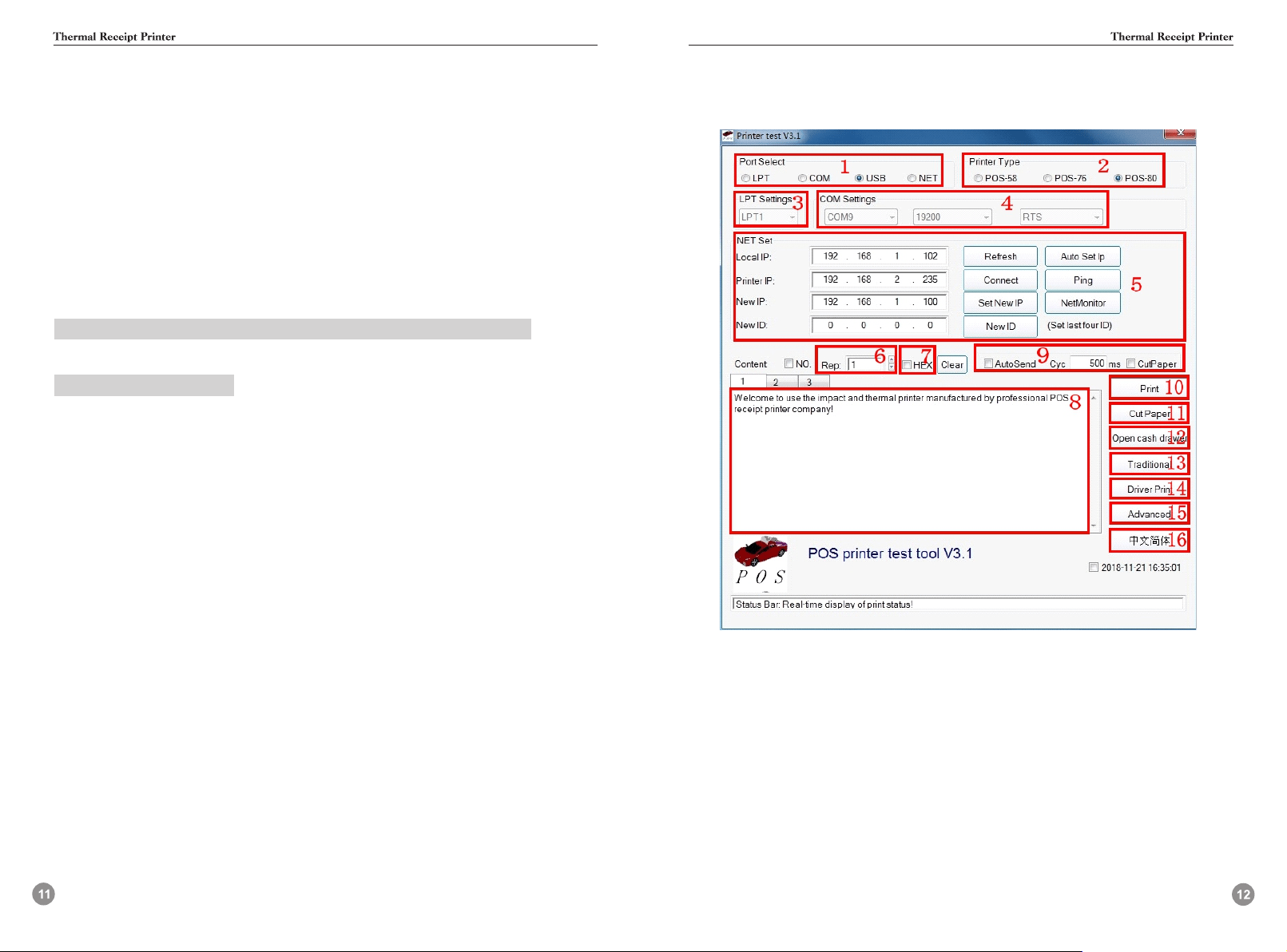
I. Introduction of Main Interface
1.Communication port selection:
Four options of printer communication interface: parallel port, serial port, USB port and Ethernet port.
2.Printer type selection:
Printer type: default to POS-80
3.Parallel port Settings (LPT Set):
Parallel port Settings ---be consistent with the computer communication parallel port number.
4.Serial port Settings (COM Set):
Serial port Settings --- set the serial port number, baud rate, flow control, etc.
5.Ethernet port Settings (NET Set):
Change the IP address of Ethernet port printer through Ethernet port Settings.
“Local IP”--- computer’s real IP address which can be added manually or by Clicking “refresh”
button.
“Printer IP”---printer’s current IP address , its detailed information can be seen on self- test page,
only suitable for Ethernet port printers.
“New IP address”--- the new IP address the printer’s IP address is to be changed to (printer’s IP address
shall be in the same network segment as the connected computer’s to realize intercommunication).
“New ID address”--- the new ID address the printer’s ID address is to be changed to(Printer’s ID
address must be an only address within a network).
Ethernet port settings are operated by means of HUB and SWITCH, in case that the settings can’t
bechanged by ROUTER, other means can be used, please refer to the PDF in the folder "IP address
changes. and other functional specification" on the CD.
“Auto Set IP”---Used to search printers in the same LAN
“Net Monitor”---Monitor printer status through network.(net port available)
6.Number of the copies:
It refers to the printing quantity of the repeat print of the test content.
7.HEX
Data can only be transmitted by inputting hexadecimal after having selected printing content.
(It’s mainlyused to send instructions to the printer).
8.Printing content:
Edit the printing content here, and send data by clicking "Print" button.
9.Automatically sending, cycle, paper cutting:
“Automatically sending”--- Click the "Auto Send" button and the software will automatically
send the data in the printing content column to the printer.
“Cycle”--- cycle time to send data automatically
“Paper cutting”--- Printer will automatically do paper cutting work according to the cycle time after
the “Auto Send ” button and “cyc” botton have been set.
10.Print:
Print the information and data in the “content”edit box.
11.Paper cutting:
Test the function of paper cutting action.
12.Open cash drawer:
Test the cashbox function
13. Traditional font test:
Used for testing traditional fonts printing
14.Driver print:
Call the installed Windows driver to test print, printing out the information suggests successful
installation
15.Advanced:
Click “advanced” button, and set up more features to have print test, below is the detailed introduction.
16.English:
It’s for switching software interfaces between English and Chinese.
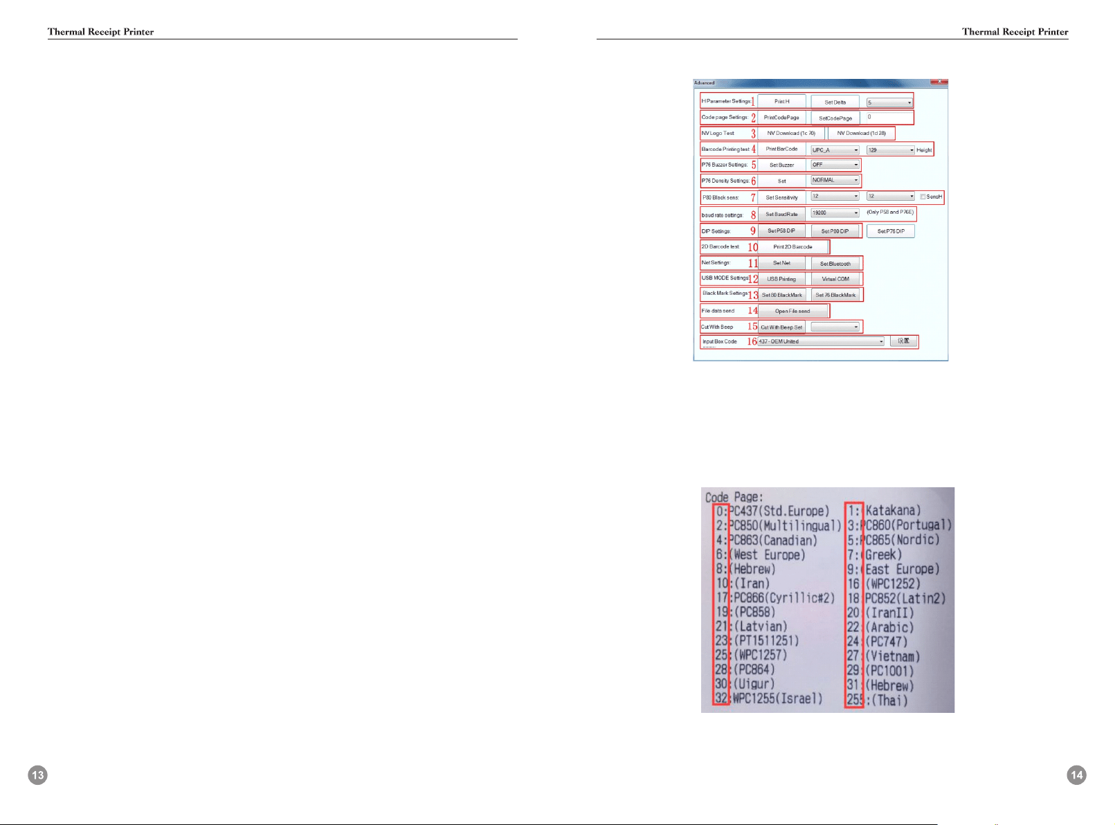
II.Setup instructions for “advanced” button
1.Set H parameter:
Its Main function is for definition adjusts of the 76 series needle printer. First click “Print H”, and
the printer will print 16 groups of H letters from 0 to F, then set "Set delta” button by choosing
the clearest Group.
2.Set Code page:
It’s for changing the default printer code page. Following is part of the code pages of the 80 series
machine,
Input the desired parameter value in “Set code page”, and then complete the setting by clicking
“set code page” button. Click "print code page” button to view the setup code.
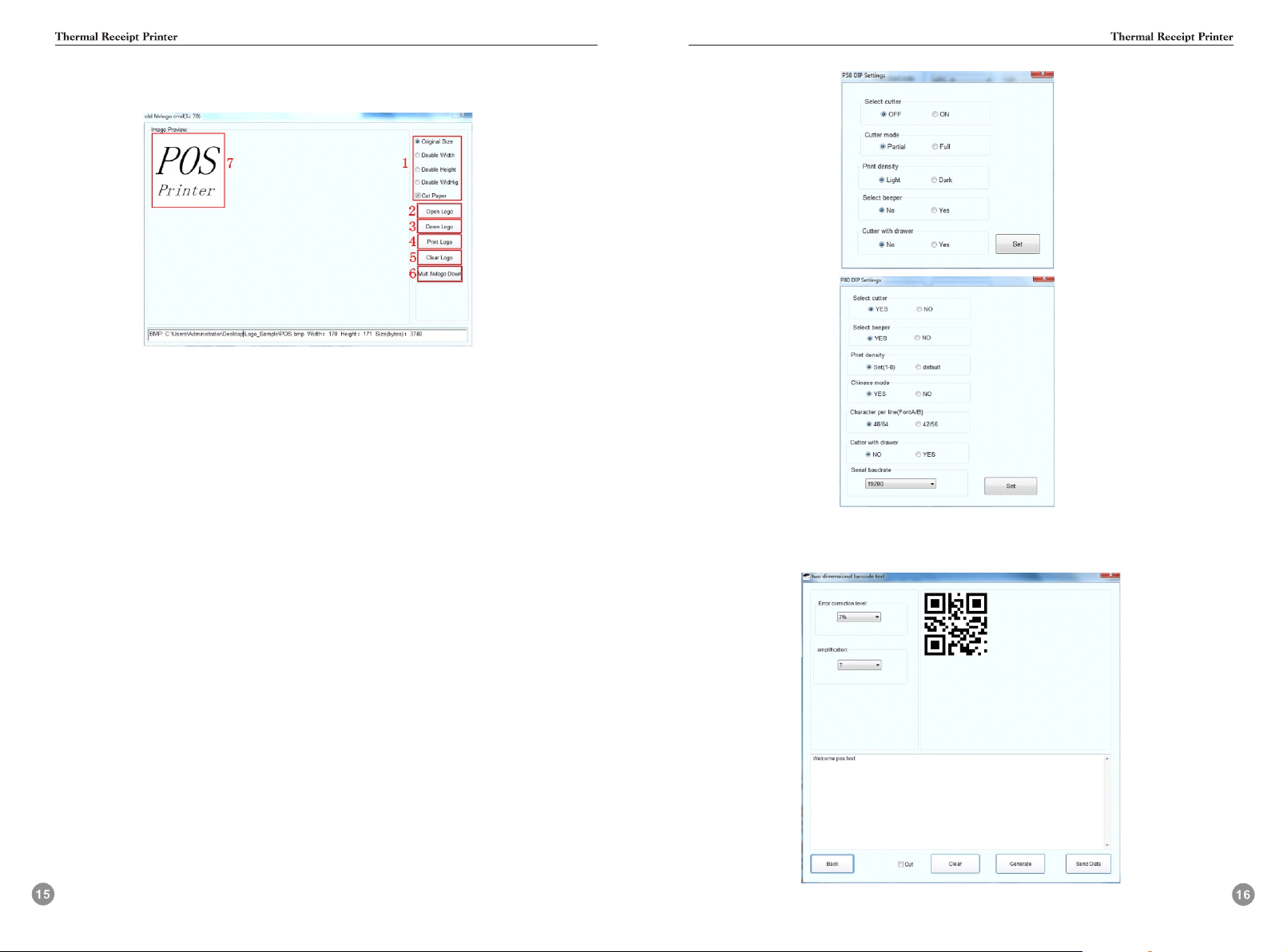
3. NV logo demo:
Click the “NV download ”button, the menu below will pop-up:
3.1 Size requirement and function selection of paper cutting of NV LOGO printing.
3.2 Open LOGO:
Click and select BMP format picture or the LOGO file that you want to print.
3.3 Download NV LOGO:
Click the download button after opening the BMP format file and the file will be downloaded to the
printer.Print the file content by clicking “print LOGO” button.
3.4 Print LOGO:
Click this button to complete the LOGO image printing.
3.5 Clear LOGO:
Remove the downloaded NV LOGO.
3.6 Mult NV LOGO down.
3.7 Show current NV LOGO
4.Barcode printing test:
Choose a variety of barcode types and height to test the print with a total of nine kinds of
one-dimensional code choice.
5.P76 Buzzer Settings:
It’s a setting for turning on or off the beeper for part of the 76 series machines.
6.P76 Printing density Settings:
To adjust the printing effect of 76 series machine, there are modes: LIGHT、NORMAL、DARK.
7.P80 Black mark sensitivity Settings:
The adjustment of black mark sensitivity Settings for 80 series machines according to different
black markpaper. Valid only when black mark function set is on.
8.Serial port baud rate Settings: (only for 58 series and P76E machines)
To set different baud rate (such as: 9600, 19200, 38400, etc.)
9.DIP switches Settings:
Threemodes:58series,80series(only for machines without dial switches)
(58series)
(80series)
10. 2D barcode testing:
Edit and print test of two-dimension codes
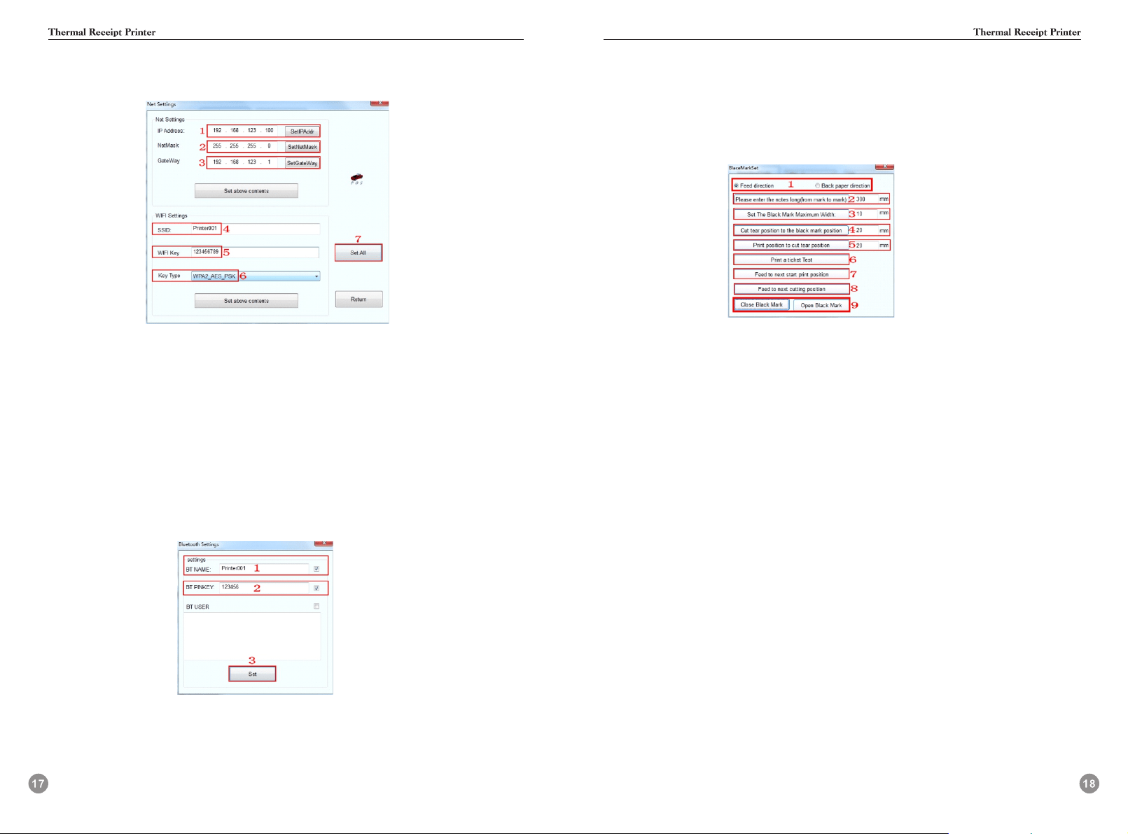
11.“ Network Settings”
It includes “Network Settings” and “Bluetooth Settings”
(Network Settings)
11.1 Set up the Printer’s IP address.
11.2 Set up the Subnet Mask.
11.3 Set up the Gateway.
11.4 WIFI SSID address settings. Note: the SSID address is the name of your Wireless Router ’s name.
For example, if the address of the current Router (SSID) is: Pinter001, then this SSID address
should be typed in the tab of “SSID”.
11.5 WIFI password settings. Note: the password of the Wireless Router
For example, if the WIFI’s
current password is:123456789, then this password should be typed in the tab of “WIFI password”.
11.6 Encryption type of WIFI SSID settings. Note: the encryption type of the Wireless Router.
For example, if the encryption type of the Router (SSID) is: WPA_TKIP_AES_PSK, then this
information should be selected in the tab of “SSID Encryption type”.
11.7 After filling the above information, click the “Setting All” option. The printer will “BEEP”.
Next, restart the printer.
(Bluetooth Settings)
11.7.1 Set up the Port name of the Bluetooth Printer (the Factory Default BT NAME is “Printer001”)
11.7.2 Set up the Password of the Bluetooth Printer (the Factory Default BT PINKEY is “123456”)
11.7.3 After finishing the above settings, click “Setting”, and then finished the settings of Bluetooth
printerParameters.
12.“USB Mode Setting”
Mode Setting of printer’s USB port includes Usb Printing and Virtual Com. USB mode switches
accordingto customer demand. For specific operation, refer to file “instructions of switching
between USB port andvirtual Com "in the folder “IP address change and other functional
specification”
13.“Black mark Settings”
To set special paper printing with black mark.
13.1 Offset in paper-feed direction, offset in paper unwinding direction
To set the direction of data calculation for paper cutting position, the default value is feed direction.
13.2 “Please enter the black mark spacing (mark length)” To calculate the center distance of two
black marks.
13.3 “Set the black mark Maximum width”
It’s a value to calculate the actual height of a black mark.
13.4 “the offset of paper cutting position relative to the black mark position”
It’s to calculate the actual distance from the paper detector in the print head to the paper cutter.
13.5 “Distance between the print starting position and paper cutting position”
It’s to calculate the distance from the print starting position to paper cutting position.
13.6 “Print a ticket test”
Click this button and a note will be printed out. If it’s properly set, paper will automatically go a
length of black mark and then be cut.
13.7 “feed to next print position”
Click this button and paper will go to the next print starting position for a blace marker. Print out
the information to test the right position.
13.8 “feed to the next cutting position”
Click this button and paper will go to the next paper cutting position and paper will be cut to test
the accuracy of paper cutting position.
13.9 Turn on the black mark, turn off the black mark
Black mark function is off by default. Turn on black mark function to make related Settings. In case
black mark position is detected incorrect, please reset referring to 7 “P80 black mark sensitivity”
of “advanced”.
14.“Send file data”
Click button,choose and open TXT format file in the pop-up dialog box, and then the printer will print the
contents of the file.
15.“Cut With Beep”
The alarm function can be set to turn on or off after cutting paper with cutter.
16.“Input BOX Code Page”
Words responsible for decoding text boxes.
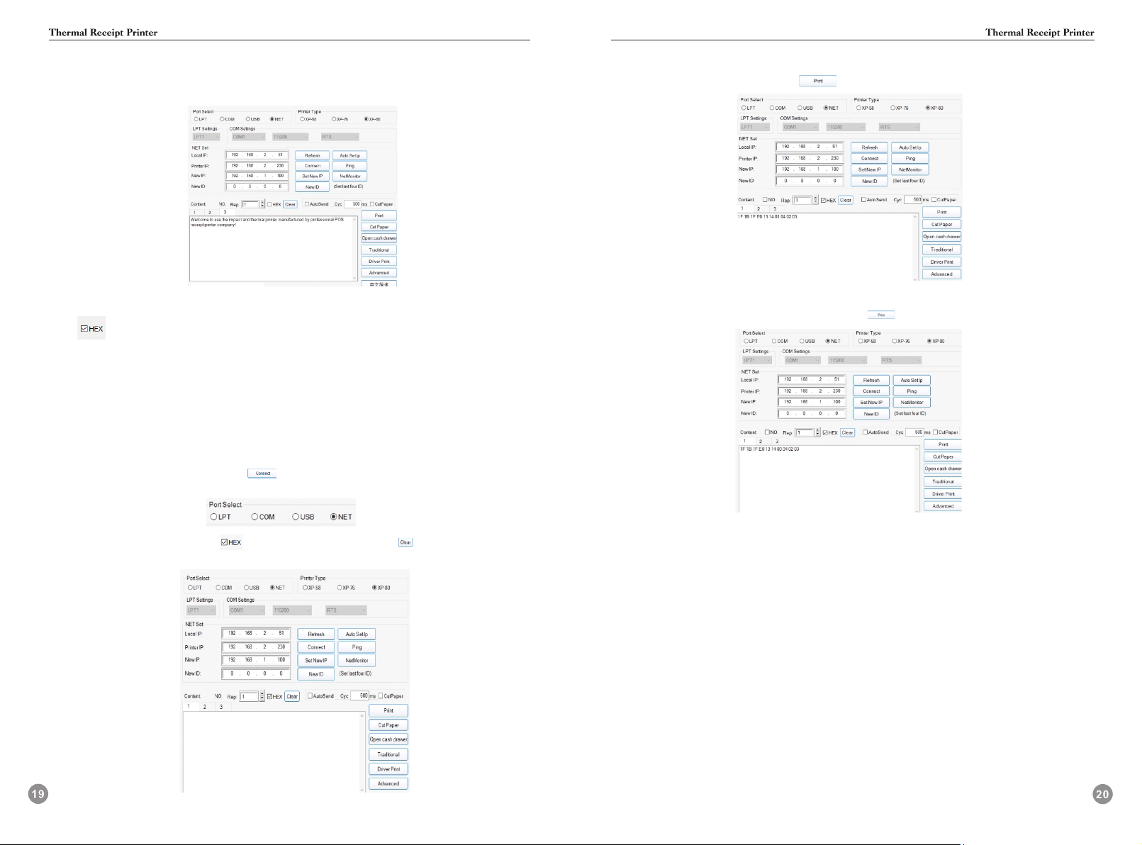
Instruction input introduction:
S1:OPEN the V3.1C tool as shown below:
S2: When sending data in hexadecimal format,please display it as shown below:
S3:Enter the print data in hexadecimal format and press the “Print” button to complete the
data entry and transmission.
Take the sound and light alarm function switch operation instructions as an example:
① Cutter with alarm on/off:1F 1B 1F E0 13 14 m 04 02 03
S1:OPEN the V3.1C tool as shown below
S2:Select the corresponding interface .If the serial port needs to set the baudrate,the printer
baudrate can be obtained by printing the selftest.The network port needs to set the IP address.
For the operation mode,refer to the following network IP setting instructions.After the setting is
completed,click the “Connect” button( ),and the connection success prompt indicates that
the network connection is successful.Select the area of the interface as shown below:
S3:Check the “HEX” option box( ) and click the “Clear” button( )to clear the contents of
text input box.The result is shown below:
S4:If you need to turn on the “cutting with alarm” function,enter the command as shown in the
text box and click the “Print” button( )to send it.
Conversely,if you want to turn off the“cutting with alarm” function,enter the command as
shown in the text box and click the “Print” button( ) to send it.
②Cutter idle alarm on/ off:1F 1B 1F A0 mode 00 0A 00 FF
The operation is the same as ①
1 Font size
GS !
[Name] Select character size
[Format] ASCII code GS ! n
Hexadecimal code 1D 21 n
Decimal code 29 33 n
[Range] 0 ≤ n ≤ 7, ,16 ≤ n ≤ 23,32 ≤ n ≤ 39,48 ≤ n ≤ 55,
64 ≤ n ≤ 71, 80 ≤ n ≤ 87, ,96 ≤ n ≤ 103, 112 ≤ n ≤ 119
1 ≤ Vertical magnification ≤ 8, 1 ≤ Horizontal magnification ≤ 8
[Description] Use the 0th to 2nd digits to select the character height,4 to 6 digits to select the
character width, and 3,7 digits to be 0,which is 0XXX0XXX.
Magnification table
H o r iz ont a l
m a g n ifica t ion
Ve rt ic a l
m a g n ifica t ion
1 2 3 4 5 6 7 8
H e x D EC He x D EC H e x D EC H ex DEC H ex D EC H ex D EC H e x D EC H e x D EC
1 0 0 0 1 0 1 6 2 0 3 2 3 0 4 8 4 0 6 4 5 0 8 0 6 0 9 6 7 0 1 1 2
2 0 1 1 1 1 1 7 2 1 3 3 3 1 4 9 4 1 6 5 5 1 8 1 6 1 9 7 7 1 1 1 3
3 0 2 2 1 2 1 8 2 2 3 4 3 2 5 0 4 2 6 6 5 2 8 2 6 2 9 8 7 2 1 1 4
4 0 3 3 1 3 1 9 2 3 3 5 3 3 5 1 4 3 6 7 5 3 8 3 6 3 9 9 7 3 1 1 5
5 0 4 4 1 4 2 0 2 4 3 6 3 4 5 2 4 4 6 8 5 4 8 4 6 4 1 0 0 7 4 1 1 6
6 0 5 5 1 5 2 1 2 5 3 7 3 5 5 3 4 5 6 9 5 5 8 5 6 5 1 0 1 7 5 1 1 7
7 0 6 6 1 6 2 2 2 6 3 8 3 6 5 4 4 6 7 0 5 6 8 6 6 6 1 0 2 7 6 1 1 8
8 0 7 7 1 7 2 3 2 7 3 9 3 7 5 5 4 7 7 1 5 7 8 7 6 7 1 0 3 7 7 1 1 9
①Test case:
1B 40
1D 21 11
B1 B6 B8 DF B1 B6 BF ED B5 C4 41 0A
1D 21 33
34 B1 B6 B8 DF BF ED 0A
②Print result description:
The “double height-width A” of the first line is the result of twice the horizontal and vertical
magnification; the “four times the height and width” of the second line is the result of quadrupling
both horizontal and vertical;(Chinese characters and alphanumeric characters can be amplification)
③Instruction setting calculation instructions:
According to the need to horizontally zoom in multiples to look up the table,such as 2 times the
width and height to choose 1D 21 11
2 Density setting
1F 1B 1F 13 14 n
[Name] Set the density level
Decimal code 31 27 31 19 20 n
[Description] Set the density level
[Range] 1<=n< = 8
[Format] Hexadecimal code 1F 1B 1F 13 14 n
3 Sound and light alarm on/off
Cutter with alarm on/off:1F 1B 1F E0 13 14 m 04 02 03
m=1: Cutter with alarm :on
[Comment] Data filtering beyond the parameter range, the higher the concentration level,
the higher the concentration.
[Default] n=5
1F 1B 1F 13 14 07 set density level 7
m=0: Cutter with alarm :off
Cutter idle alarm on/off:1F 1B 1F A0 mode 00 0A 00 FF
Test case:
mode=1:Cutter idle alarm on
mode=0:Cutter idle alarm off
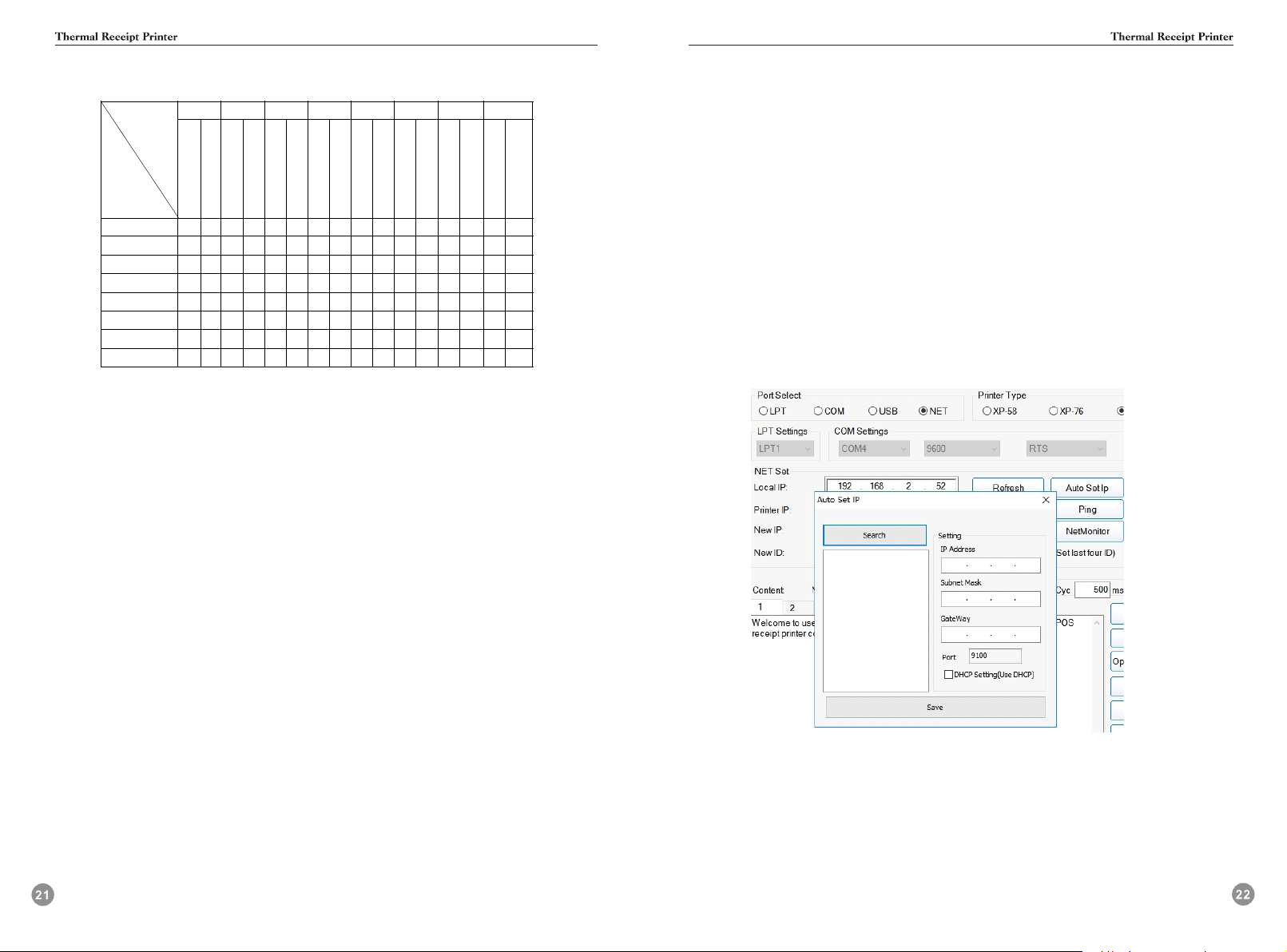
4 IP address setting method
Single network port model setting method:
S1: Open the V3.1C tool
S2: Communication port selection network port
S3: Click“Auto Set Ip” ->click“Search”-> select the IP address of the printer you want to set ->
Modify IP address and gateway parameters -> click“Save”(see Figure 1)
S4: The buzzer sounds and the printer restarts to indicate that the setting is successful.
S5: Print a self-test page to check if the IP address is set correctly.
Figure 1
S5: Print a self-test page to check if the IP address is set correctly.
Note: The serial port needs to set the correct baud rate.
Figure 2
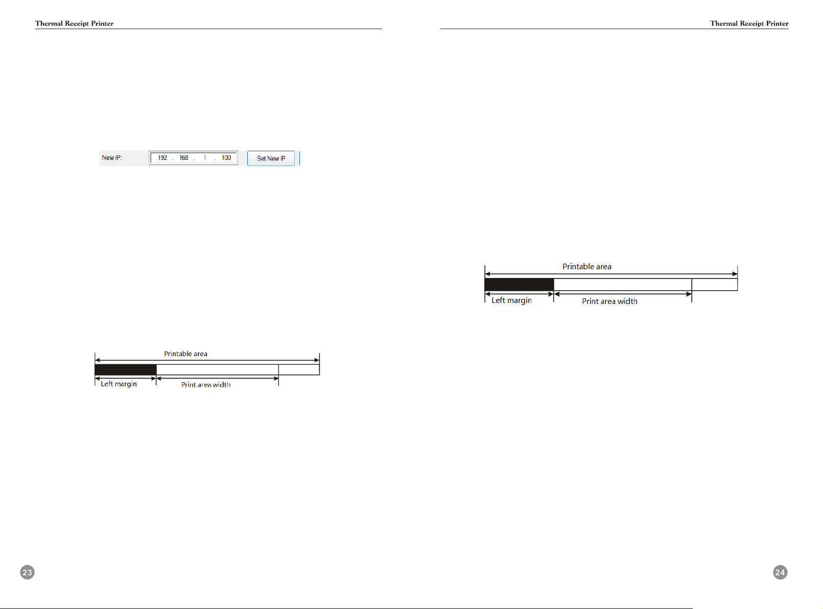
5 Print margins
GS L
[Name] Set the left margin
[Format] ASCII code GS L nL nH
Hexadecimal code 1D 4C nL nH
Decimal code 29 76 nL nH
[Range] 0 ≤ nL ≤ 255
0 ≤ nH ≤ 255
[Description] • Set the left margin with nL and nH;
• The left margin is set to [( nL + nH × 256) × Horizontal moving unit]].
①Test case:
1B 40
1D 4C 00 00
41 41 41 41 41 41 41 41 41 41 41 41 41 41 41 41 41 41 41 41 41 41 41 41 41 41 41 41 41 41 41 41 41
41 41 41 41 41 41 41 41 41 41 41 41 41 41 41 41 41 41 41 41 4141 41 41 41 41 41 41 41 41 41 41 41
41 41 41 41 41 41 41 41 41 41 41 41 41 41 41 41 41 41 41 41 41 41 41 41 41 41 41 41 41 41 41 41 41
41 41 41 41 41 41 41 41 41 41 41 41 41 41 41 41 41 41 41 41 41 41 41 41 41 41 41 41 41 41 41 41 41
41 41 41 0a
1D 4C 20 00
41 41 41 41 41 41 41 41 41 41 41 41 41 41 41 41 41 41 41 41 41 41 41 41 41 41 41 41 41 41 41 41 41
41 41 41 41 41 41 41 41 41 41 41 41 41 41 41 41 41 41 41 41 4141 41 41 41 41 41 41 41 41 41 41 41
41 41 41 41 41 41 41 41 41 41 41 41 41 41 41 41 41 41 41 41 41 41 41 41 41 41 41 41 41 41 41 41 41
41 41 41 41 41 41 41 41 41 41 41 41 41 41 41 41 41 41 41 41 41 41 41 41 41 41 41 41 41 41 41 41 41
41 41 41 0a
②Print result description:
The left margin of the first three lines is 0 ( the left and right fixed margins are not counted),
and the left margin of the last three lines is 4 mm.
③Instruction setting calculation instructions:
Set the left margin 4mm= ( nL + nH × 256)* 0. 125mm
nL=32, nH= 0,
Convert to hexadecimal data nL=20, nH= 00
GS W
[Name] Set the print area width
[Format] ASCII code GS W nL nH
Hexadecimal code 1D 57 nL nH
Decimal code 29 87 nL nH
[Range] 0 ≤ nL ≤ 255
0 ≤ nH ≤ 255
[Description] Set the printa rea width with nL and nH.
Set the print area width to [ (nL+nH ×256)×Horizontal moving unit]] .
①Test case:
1B 40
41 41 41 41 41 41 41 41 41 41 41 41 41 41 41 41 41 41 41 41 41 41 41 41 41 41 41 41 41 41 41 41 41
41 41 41 41 41 41 41 41 41 41 41 41 41 41 41 41 41 0a
1D 57 D0 01
41 41 41 41 41 41 41 41 41 41 41 41 41 41 41 41 41 41 41 41 41 41 41 41 41 41 41 41 41 41 41 41 41
41 41 41 41 41 41 41 41 41 41 41 41 41 41 41 41 41 0a
②Print result description:
The A print width of the first two lines is the default of 72 mm, and the A print width
of the last two lines is 58 mm.
③Instruction setting calculation instructions:
Set the print width 58mm= ( nL + nH × 256)* 0.125mm
nL=208, nH= 1,
Convert to hexadecimal data nL=D0, nH= 01
Non-single network port model setting method
S1 Open the V3.1C tool
S2 The communication port selects the remaining interfaces,which can be USB/serial/parallel
S3 Modify the IP address at the“New IP”and click Set New IP (see Figure 2).
S4 The buzzer sounds and the printer restarts to indicate that the setting is successful