Loading ...
Loading ...
Loading ...
ASSEMBLY
Assembling the loop handlebar
(325C, 325Cx)
• Position the handle on
the shaft. Note that the
handle must be mounted
below the arrow on the
shaft.
• Fit tile bolt, securing plate
and wing nut as shown in
the diagram.
• Tighten the wing nut.
Assembling the loop handlebar
(322L, 323L, 325Lx, 325Lxv 325LDx)
• Clip the loop handle onto
the shaft. Note that the
loop handle must be
fitted between the arrows
on the shaft.
• Slide the spacer into the
slot in the loop handle.
• 322L/323L: Fit the nut,
washer and bolt.
325Lx/325Lx/325LDx:
Fit tile nut, knob and
bolt. Do not overtighten.
• Now adjust the trimmer
to give a comfortable
working position. Tighten
the bolt/knob.
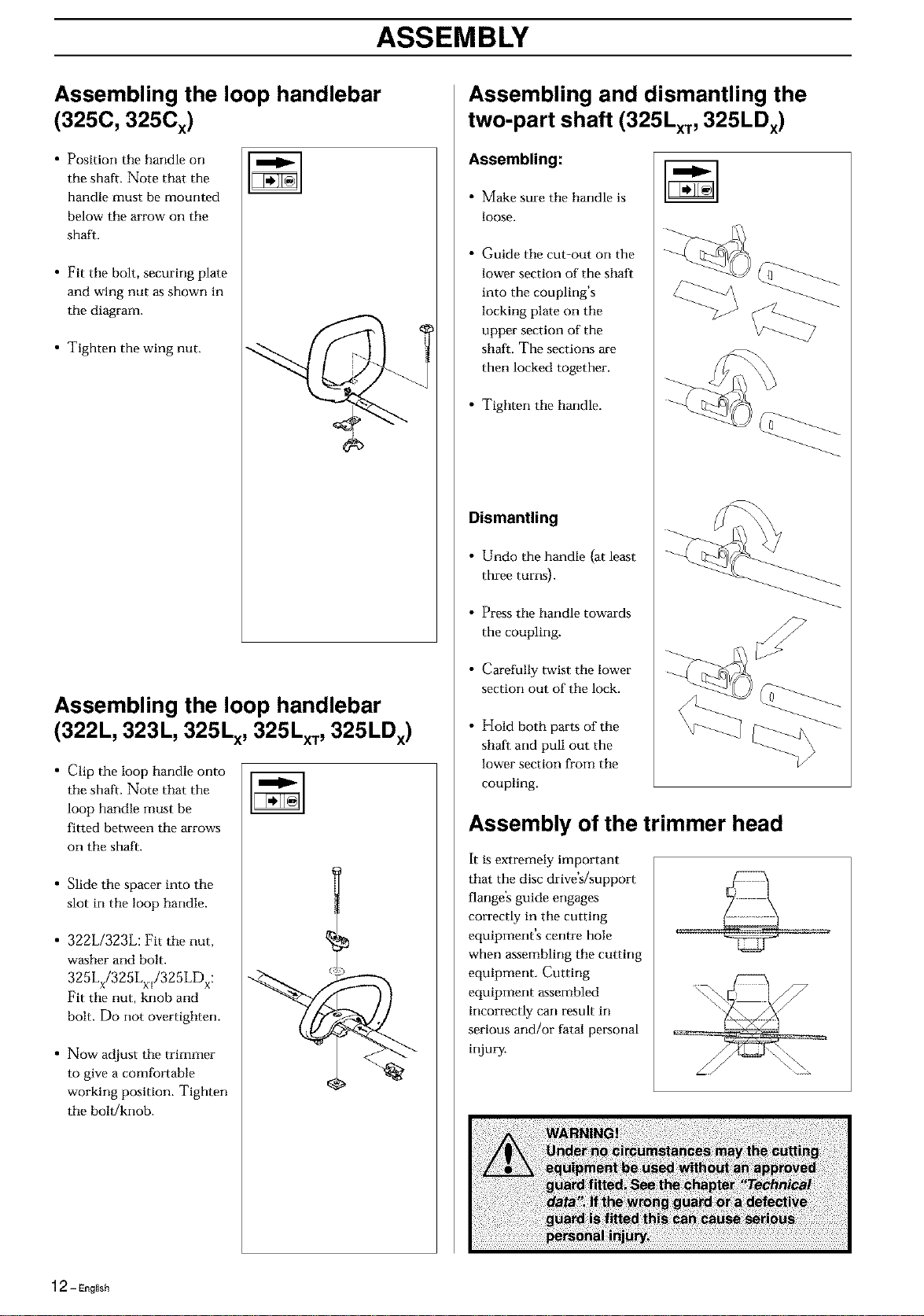
Assembling and dismantling the
two-part shaft (325Lxv 325LDx)
Assembling:
• Make sure the handle is
loose.
• Guide tile cut-out on the
lower section of the shaft
into the coupling's
locking plate on the
upper section of the
shaft. The sections are
then locked together.
• Tighten the handle.
Dismantling
• Undo the handle (at least
three turns).
• Press the handle towards
the coupling.
• Carefully twist the lower
section out of the lock.
• Hold both parts of the
shaft and pull out the
lower section from the
coupling.
Assembly of the trimmer head
It is extremely important
that the disc drive's/support
flange's guide engages
correctly in tile cutting
equipment's centre hole
when assembling the cutting
equipment. Cutting
equipment assembled
incorrectly can result in
serious and/or fatal personal
injury.
12 - English
Loading ...
Loading ...
Loading ...