

Information in this document is subject to change without notice. Reproduction in any manner whatsoever,
without the written permission of D-Link Corporation, is strictly forbidden.
Trademarks used in this text: D-Link and the D-LINK logo are trademarks of D-Link Corporation; Microsoft and
Windows are registered trademarks of Microsoft Corporation.
Other trademarks and trade names may be used in this document to refer to either the entities claiming the
marks and names or their products. D-Link Corporation disclaims any proprietary interest in trademarks and trade
names other than its own.
© 2022 D-Link Corporation. All rights reserved.
May, 2022 P/N 651GS15100A5G
FCC Compliance Statement
This device complies with Part 15 of the FCC Rules. Operation is subject to the following two conditions: (1) This
device may not cause harmful interference, and (2) this device must accept any interference received, including
interference that may cause undesired operation.
CE Mark Warning
This equipment is compliant with Class A of CISPR 32. In a residential environment, this equipment may cause
radio interference.
Avertissement Concernant la Marque CE
Cet équipement est conforme à la classe A de la norme CISPR 32. Dans un environnement résidentiel, cet
équipement peut provoquer des interférences radio.
VCCI Warning
この装置は、クラス A 機器です。この装置を住宅環境で使用すると電波妨害を引き起こすことがあります。この
場合には使用者が適切な対策を講ずるよう要求されることがあります。 VCCI-A
BSMI Notice
此為甲類資訊技術設備,於居住環境中使用時,可能會造成射頻擾動,在此種情況下,使用者會被要求採取某些適
當的對策。
Safety Compliance
Warning: Class 1 Laser Product: When using a fiber optic media expansion module, never look at the transmit
laser while it is powered on. In addition, never look directly at the fiber TX port and fiber cable ends when they
are powered on.
Avertissement: Produit Laser de Classe 1: Ne regardez jamais le laser tant qu’il est sous tension. Ne regardez
jamais directement le port TX (Tramsmission) à fibres optiques et les embouts de câbles à fibres optiques tant
qu’ils sont sous tension.

DGS-1510 Series Gigabit Ethernet SmartPro Switch Hardware Installation Guide
iii
Table of Contents
Intended Readers ........................................................................................................................................................ v
Typographical Conventions ......................................................................................................................................... v
Notes, Notices, and Cautions ...................................................................................................................................... v
1. Introduction ................................................................................................................................................................ 6
Switch Description ....................................................................................................................................................... 6
Package Contents ........................................................................................................................................................ 6
Features ....................................................................................................................................................................... 6
Front-Panel Components ............................................................................................................................................. 8
Ports ........................................................................................................................................................................ 9
Reset Button ......................................................................................................................................................... 10
LED Indicators ...................................................................................................................................................... 10
Rear Panel Components ............................................................................................................................................ 13
Side Panel Components ............................................................................................................................................ 14
Smart Fans ........................................................................................................................................................... 16
2. Installation ................................................................................................................................................................ 18
Installation Guidelines ................................................................................................................................................ 18
Installing the Switch without a Rack ..................................................................................................................... 18
Attaching Brackets to a Switch for Rack Mounting ............................................................................................... 18
Installing the Switch in a Standard 19" Rack ........................................................................................................ 19
Installing Transceivers into the Transceiver Ports ................................................................................................ 20
Power On (AC Power) ............................................................................................................................................... 20
Power Failure (AC Power) .................................................................................................................................... 21
Installing Power Cord Clip .................................................................................................................................... 21
Installing the RPS into a Rack-mount Chassis .......................................................................................................... 24
DPS-700 ............................................................................................................................................................... 24
3. Connecting the Switch............................................................................................................................................. 26
Switch to End Node ................................................................................................................................................... 26
Switch to another Switch ............................................................................................................................................ 26
Switch to a Server ...................................................................................................................................................... 27
4. Introduction to Switch Management ...................................................................................................................... 28
Management Options ................................................................................................................................................. 28
Connecting the Console Port ..................................................................................................................................... 28
Connecting to the Switch for the First Time .......................................................................................................... 30
Creating a User Account ....................................................................................................................................... 31
Configuring the IP Address ................................................................................................................................... 31
SNMP Settings ........................................................................................................................................................... 32
Traps ..................................................................................................................................................................... 33
Management Information Base (MIB) ................................................................................................................... 33
5. Web-based Switch Configuration ........................................................................................................................... 34
Introduction ................................................................................................................................................................ 34
Logging onto the Web Manager ................................................................................................................................ 34
Web-based User Interface ......................................................................................................................................... 35
Areas of the User Interface ................................................................................................................................... 35
Appendix A – Technical Specifications ...................................................................................................................... 37
General ...................................................................................................................................................................... 37
Physical and Environmental....................................................................................................................................... 37
Performance............................................................................................................................................................... 39
LED Indicators ........................................................................................................................................................... 41
Per Switch ............................................................................................................................................................. 41

DGS-1510 Series Gigabit Ethernet SmartPro Switch Hardware Installation Guide
iv
Per RJ45 Port ....................................................................................................................................................... 41
Per SFP Port ......................................................................................................................................................... 42
Per SFP+ Port ....................................................................................................................................................... 42
Port Functions ............................................................................................................................................................ 42
Appendix B – Cables and Connectors ........................................................................................................................ 45
Ethernet Cable ........................................................................................................................................................... 45
Console Cable ........................................................................................................................................................... 46
Redundant Power Supply (RPS) Cable ..................................................................................................................... 47
Appendix C – ERPS Information.................................................................................................................................. 49
Safety/Sécurité .............................................................................................................................................................. 50
Safety Instructions ..................................................................................................................................................... 50
Safety Cautions .................................................................................................................................................... 50
Consignes de sécurité ............................................................................................................................................... 51
Précautions de sécurité ........................................................................................................................................ 51
General Precautions for Rack-Mountable Products .................................................................................................. 53
Protecting Against Electrostatic Discharge ................................................................................................................ 54
Warranties & Technical Support................................................................................................................................... 55

DGS-1510 Series Gigabit Ethernet SmartPro Switch Hardware Installation Guide
v
Intended Readers
Intended Readers
Typographical Conventions
Notes, Notices, and Cautions
Safety Instructions
General Precautions for Rack-Mountable Products
Protecting Against Electrostatic Discharge
The DGS-1510 Series Hardware Installation Guide contains information about the configuration and
management of the switch. This manual is intended for network administrators familiar with network
management concepts and terminology. For all practical reasons all the switches in this series will
simply be referred to as the Switch throughout this manual. All example screenshots are taken from
the DGS-1510-28XMP switch.
Typographical Conventions
Convention Description
[ ]
In a command line, square brackets indicate an optional entry. For
example: [copy filename] means that optionally you can type copy
followed by the name of the file. Do not type the brackets.
Bold Font Indicates a button, a toolbar icon, menu, or menu item. For
example: Open the File menu and choose Cancel. Used for
emphasis. May also indicate system messages or prompts
appearing on screen. For example: You have mail.
Courier New Font
Indicates commands and responses to prompts that must be typed
exactly as printed in the manual.
Initial capital letter
Indicates a window name. Names of keys on the keyboard have
initial capitals. For example: Click Enter.
Italics Indicates a window name or a field. Also can indicate a variables or
parameter that is replaced with an appropriate word or string. For
example: type filename means that the actual filename should be
typed instead of the word shown in italic.
Menu Name > Menu Option Menu Name > Menu Option indicates the menu structure. Device
> Port > Port Properties means the Port Properties menu option
under the Port menu option that is located under the Device menu.
Notes, Notices, and Cautions
NOTE: A note indicates important information that helps you make better use of your
device.
NOTICE: A notice indicates either potential damage to hardware or loss of data and
tells you how to avoid the problem.
CAUTION: A caution indicates a potential for property damage, personal injury, or
death.
ATTENTION: Une précaution indique un risque de dommage matériel, de blessure
corporelle ou de mort.

DGS-1510 Series Gigabit Ethernet SmartPro Switch Hardware Installation Guide
6
1. Introduction
Switch Description
Package Contents
Features
Front-Panel Components
Rear Panel Components
Side Panel Components
This Hardware Installation Guide is a detailed document explaining information about the hardware
installation, configuration, specifications, guidelines, and maintenance of a D-Link switch.
Switch Description
The DGS-1510 Series is D-Link’s next generation SmartPro Switch. It features built-in 10Gbps SFP+
ports targeted for SME/SMB core deployment to improve connectivity between core switches and
edge switches. The DGS-1510 Series also implements D-Link’s innovative 3
rd
generation Green
Ethernet technology (IEEE 802.3az) by not only saving power over inactive links, but also turning off
LEDs on a customized schedule and allowing ports to automatically enter the hibernated state.
In the DGS-1510 Series, the following switches are available: DGS-1510-20, DGS-1510-28, DGS-
1510-28P, DGS-1510-28X, DGS-1510-28XMP, DGS-1510-52, DGS-1510-52X, and DGS-1510-
52XMP. Some features, throughout this guide, will apply to all the switches within the DGS-1510
Series. When referring to these universal features, we will simply refer to the product as the Switch.
Package Contents
When purchasing a D-Link DGS-1510 Series Switch, a list of items will be included in the package of
the Switch. Open the shipping carton of the Switch and carefully unpack its contents. The carton
should contain the following items:
• One D-Link DGS-1510 Series Switch.
• One Quick Installation Guide.
• One AC power cord.
• One console cable.
• One power cord cable clip.
• One mounting kit (two brackets and screws).
• Four rubber feet with adhesive backing.
• One CD that includes a digital copy of the CLI Reference Guide, Web UI Reference Guide,
Hardware Installation Guide, D-View module, D-Link Network Assistant, and D-Link Network
Assistant Guide.
NOTE: If any item is missing or damaged, please contact your local D-Link Reseller
for replacement.
Features
The list of features below highlights the significant features of the Switch.
• Supports Virtual Stacking. D-Link Single IP Management (SIM).
• Supports Physical Stacking, using the SFP+ ports with 40G (Full Duplex) in topologies Linear
and Ring.

DGS-1510 Series Gigabit Ethernet SmartPro Switch Hardware Installation Guide
7
• Supports a 16,384 MAC address table.
• Supports Flow Control (802.3x) in full-duplex compliant.
• Supports Jumbo Frames of up to 9,216 bytes
• Supports Spanning Tree with 802.1D 2004 STP/RSTP and 802.1Q 2005 MSTP.
• Supports Loopback Detection (LBD).
• Supports Link Aggregation (802.3ad and 802.3AX) with a maximum of 32 groups per Switch.
• Supports Port Mirroring.
• Supports Layer 2 Multicast Filtering.
• Supports IGMP Snooping (v1, v2, v3 awareness) with up to 512 snooping groups and 128
static multicast addresses. MLD Snooping (v1, v2 awareness) with up to 512 snooping groups
and 128 static multicast addresses. IGMP Snooping and MLD Snooping share 128 static
groups and 512 snooping groups.
• Supports Virtual LAN (802.1Q) with up to 4K static VLAN groups and 4K dynamic VLAN
groups.
• Supports Port-based VLAN.
• Supports MAC-based VLAN.
• Supports 802.1v Protocol-based VLAN.
• Supports Asymmetric VLAN.
• Supports Auto Voice and Surveillance VLAN.
• Supports IP Interfaces with up to 16 IP interfaces.
• Supports Gratuitous ARP.
• Supports IPv6 Ready Phase 2 compliancy.
• Supports Static Routing.
• Supports Quality of Service (QoS) with Queue Handling and Class of Service (CoS).
• Supports Access Control List (ACL) with Ingress ACL, Time-based ACL, and ACL Statistics.
• Supports Secure Shell (SSHv2) with IPv4/IPv6 access.
• Supports Secure Sockets Layer (SSL) versions 1, 2, and 3 with IPv4/IPv6 access.
• Supports Port Security of up to 128 MAC addresses.
• Supports Broadcast and Multicast Storm Control.
• Supports Traffic Segmentation
• Supports D-Link SafeGuard Engine.
• Supports ARP Spoofing Prevention.
• Supports IP-MAC-Port Binding (IMPB). This feature includes DHCP Snooping, IP Source
Guard, Dynamic ARP Inspection, DHCPv6 Guard, RA Guard, IPv6 Snooping, IPv6 Source
Guard, and IPv6 ND Snooping.
• Supports DoS Attack Prevention.
• Supports Port-based Network Access Control (PNAC) better known as 802.1X. This feature
includes Local and RADIUS database, Port-based Access Control, and MAC-based Access
Control (MAC).
• Supports Web-based Access Control (WAC).
• Supports Japanese Web-based Access Control (JWAC).
• Supports Guest VLAN.
• Supports 15 User Account Privilege Levels.
• Supports Compound Authentication.
• Supports Link Layer Discovery Protocol (LLDP) with LLDP-MED.
• Supports Accessibility using multiple interfaces like the Command Line Interface (CLI), Web-
based Graphical User Interface (Web-based GUI), and more.
• Supports Telnet Server and Client from IPv4 and IPv6.
• Supports Trivial File Transfer Protocol (TFTP) Client.
• Supports Simple Network Management Protocol (SNMP) version 1, 2c, and 3. Also supports
SNMP Traps.
DGS-1510 Series Gigabit Ethernet SmartPro Switch Hardware Installation Guide
8
• Supports DHCP Client.
• Supports Dynamic Host Configuration Protocol (DHCP) Relay.
• Supports Traps and Logs.
• Support Multiple Images.
• Supports Password Encryption (MD5/SHA1).
• Supports Simple Network Time Protocol (SNTP).
• Support Power Saving using the Link Status Mode.
• Support Time-based Power-over-Ethernet (PoE).
• Supports IEEE 802.3az compliance.
• Supports Optical Transceiver Digital Diagnostic Monitoring (DDM).
• Supports D-Link Discovery Protocol (DDP).
• Supports Ethernet Ring Protection Switching (ERPS). For more information, refer to Appendix
C – ERPS Information.
• Supports Network Time Protocol (NTP).
• Supports Telnet Client.
• Supports MIBs like MIBII, Bridge MIB, SNMPv2 MIB, RMON MIB, RMONv2 MIB, Ether-like
MIB, 802.3 MAU MIB, 802.1p MIB, RADIUS Authentication Client MIB, Ping MIB, L2 Specific
MIB, Private MIB, Entity MIB, and ZoneDefense MIB.
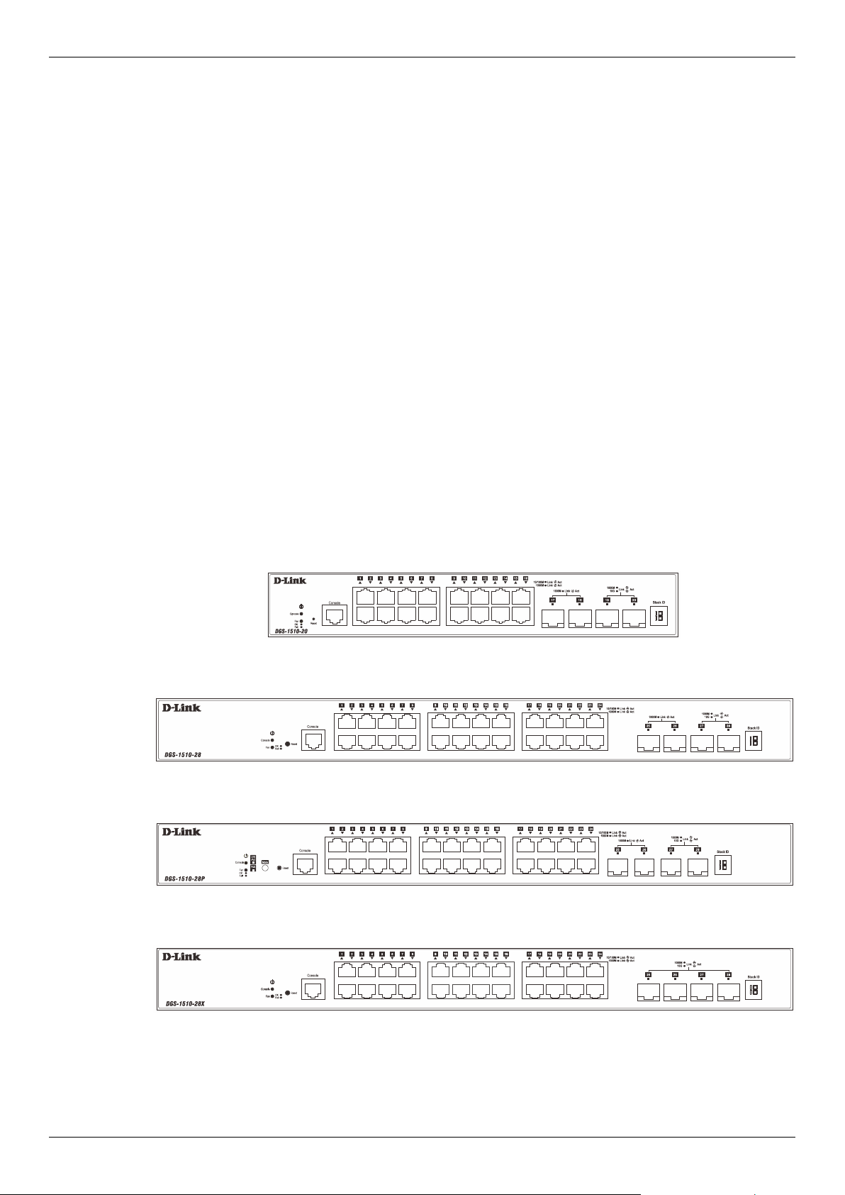
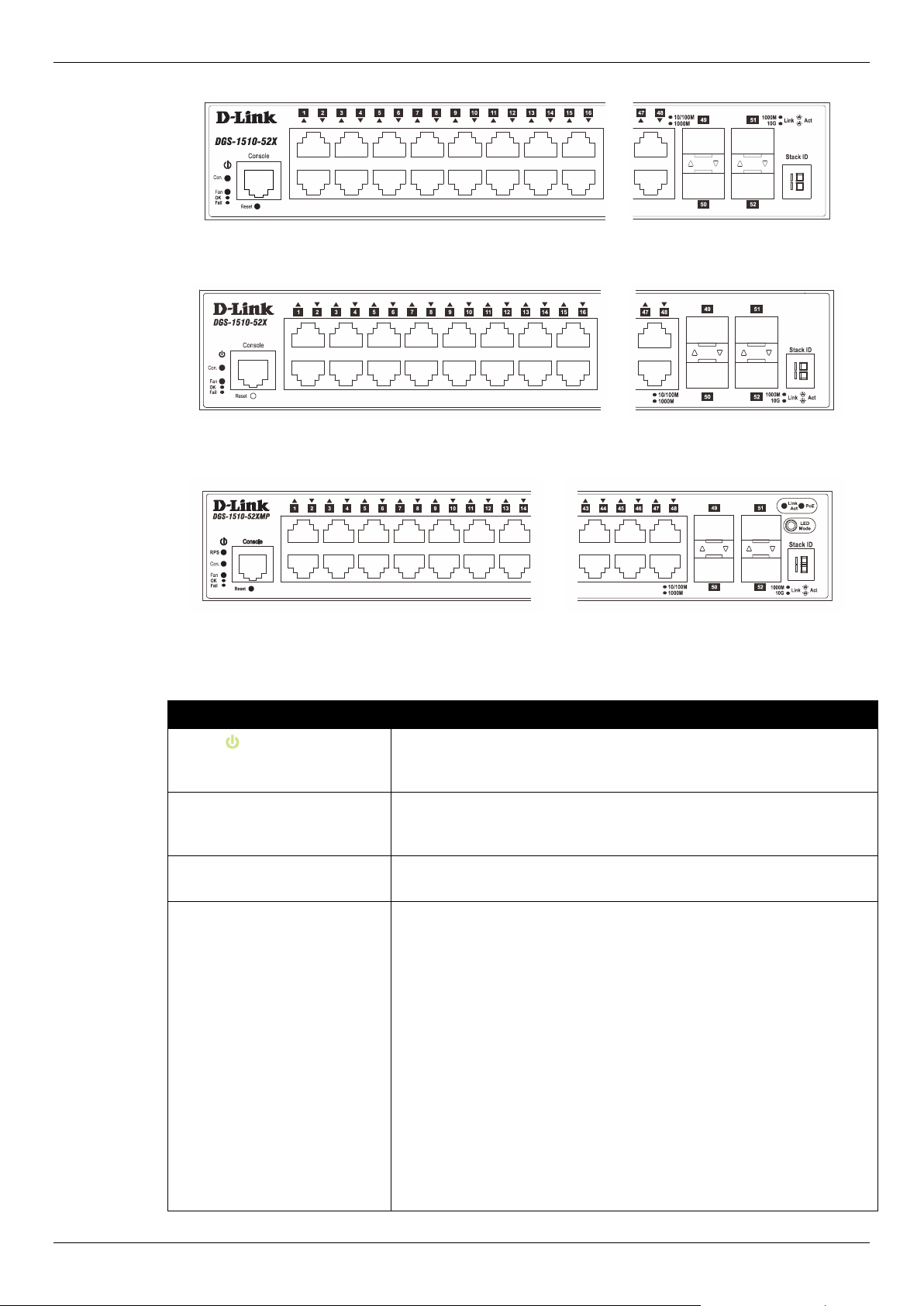
Front-Panel Components
On the front panel of the Switch there are Ethernet RJ45/SFP/SFP+ ports, a Console port, a Reset
button, a Mode button (only of PoE supported switches), and LED indicators.
Figure 1-1 Front panel view of a DGS-1510-20 Switch
Figure 1-2 Front panel view of a DGS-1510-28 Switch
Figure 1-3 Front panel view of a DGS-1510-28P Switch
Figure 1-4 Front panel view of a DGS-1510-28X Switch
DGS-1510 Series Gigabit Ethernet SmartPro Switch Hardware Installation Guide
9
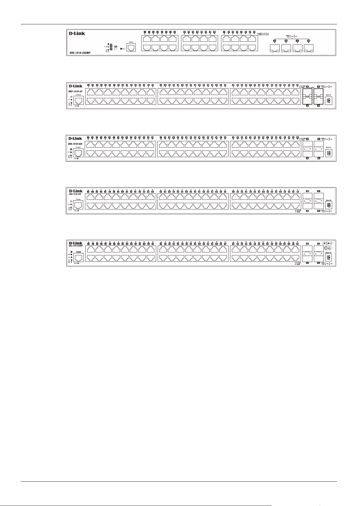
Figure 1-5 Front panel view of a DGS-1510-28XMP Switch
Figure 1-6 Front panel view of a DGS-1510-52 Switch
Figure 1-7 Front panel view of a DGS-1510-52X (HW: A1) Switch
Figure 1-8 Front panel view of a DGS-1510-52X (HW: A2) Switch
Figure 1-9 Front panel view of a DGS-1510-52XMP Switch
Ports
The Type and Number of ports available on the Switch are listed out below:
• DGS-1510-20:
o Sixteen Copper Ports (10BASE-T/100BASE-TX/1000BASE-T),
o Two SFP Ports (1000BASE),
o Two Dual Speed SFP+ Ports (1000BASE/10GBASE),
o One Console Port (RJ-45),
• DGS-1510-28:
o Twenty-four Copper Ports (10BASE-T/100BASE-TX/1000BASE-T),
o Two SFP Ports (1000BASE),
o Two Dual Speed SFP+ Ports (1000BASE/10GBASE),
o One Console Port (RJ-45),
• DGS-1510-28P:
o Twenty-four Copper PoE Ports (10BASE-T/100BASE-TX/1000BASE-T),
o Two SFP Ports (1000BASE),
o Two Dual Speed SFP+ Ports (1000BASE/10GBASE),
o One Console Port (RJ-45),
• DGS-1510-28X:
o Twenty-four Copper Ports (10BASE-T/100BASE-TX/1000BASE-T),
o Four SFP/SFP+ Ports (1000BASE/10GBASE),

DGS-1510 Series Gigabit Ethernet SmartPro Switch Hardware Installation Guide
10
o One Console Port (RJ-45),
• DGS-1510-28XMP:
o Twenty-four Copper PoE Ports (10BASE-T/100BASE-TX/1000BASE-T),
o Four SFP/SFP+ Ports (1000BASE/10GBASE),
o One Console Port (RJ-45),
• DGS-1510-52:
o Forty-eight Copper Ports (10BASE-T/100BASE-TX/1000BASE-T),
o Two SFP Ports (1000BASE),
o Two Dual Speed SFP+ Ports (1000BASE/10GBASE),
o One Console Port (RJ-45),
• DGS-1510-52X (HW: A1):
o Forty-eight Copper Ports (10BASE-T/100BASE-TX/1000BASE-T),
o Four SFP/SFP+ Ports (1000BASE/10GBASE),
o One Console Port (RJ-45),
• DGS-1510-52X (HW: A2):
o Forty-eight Copper Ports (10BASE-T/100BASE-TX/1000BASE-T),
o Four SFP/SFP+ Ports (1000BASE/10GBASE),
o One Console Port (RJ-45),
• DGS-1510-52XMP:
o Forty-eight Copper PoE Ports (10BASE-T/100BASE-TX/1000BASE-T),
o Four SFP/SFP+ Ports (1000BASE/10GBASE),
o One Console Port (RJ-45),
CAUTION: This equipment is to be connected only to PoE networks without routing to
the outside plant.
Reset Button
On the front panel of the Switch is a Reset button. The Switch will reboot or reset to factory default
settings depending on how long this button is pressed.
• Press and hold the Reset button for less than 5 seconds (release before 5 seconds) to reboot
the Switch. All unsaved configurations will be lost.
• Press and hold the Reset button for more than 5 seconds (release between 6 and 10 seconds)
to reset the software configuration of the Switch to the factory default settings. All the port LEDs
will light up (solid amber) for 2 seconds to indicate the start of the factory reset procedure.
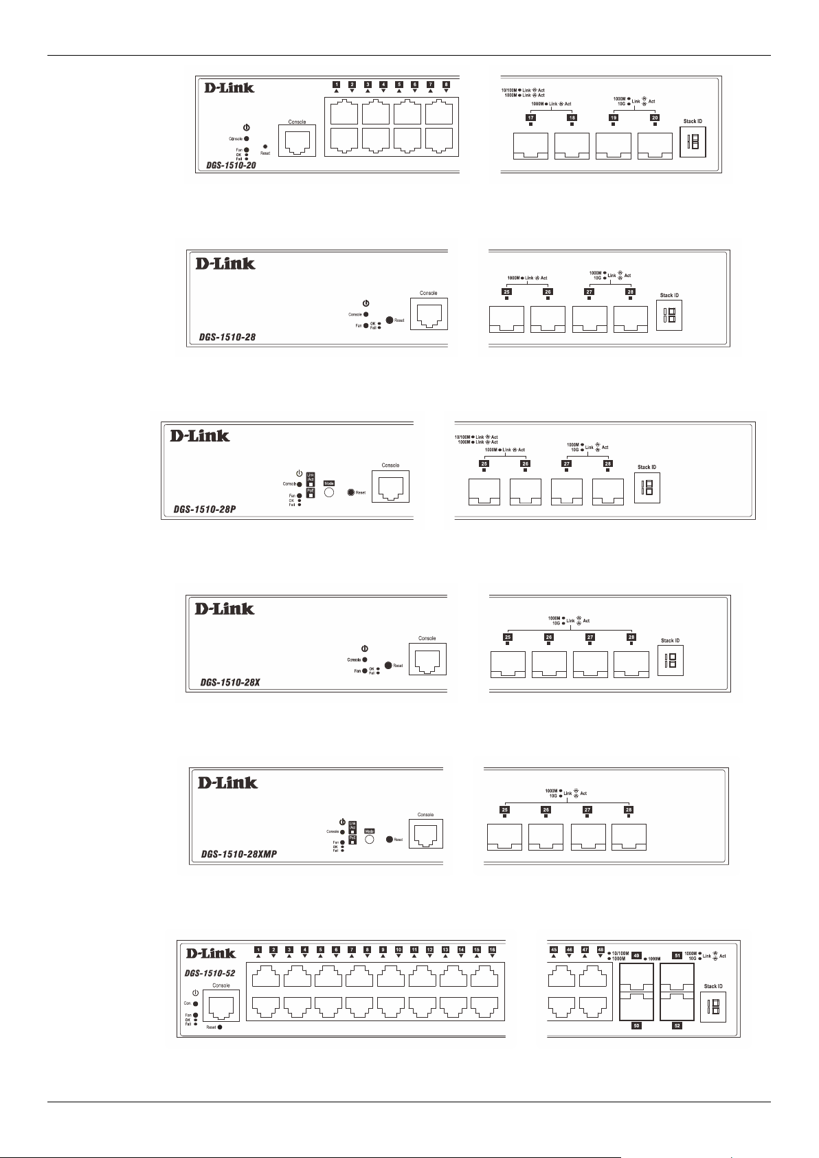
LED Indicators
The Switch’s front panel presents LED indicators for Power, Console, Master (Stack Control), Stack
ID and Link/Act indicators for all the ports. The DGS-1510-28P, DGS-1510-28XMP, and DGS-1510-
52XMP switches are equipped with an additional PoE light, to indicate whether the ports are running
in Power over Ethernet mode.
DGS-1510 Series Gigabit Ethernet SmartPro Switch Hardware Installation Guide
11
Figure 1-10 LED indicators for a DGS-1510-20 Switch
Figure 1-11 LED indicators for a DGS-1510-28 Switch
Figure 1-12 LED indicators for a DGS-1510-28P Switch
Figure 1-13 LED indicators for a DGS-1510-28X Switch
Figure 1-14 LED indicators for a DGS-1510-28XMP Switch
Figure 1-15 LED indicators for a DGS-1510-52 Switch
DGS-1510 Series Gigabit Ethernet SmartPro Switch Hardware Installation Guide
12
Figure 1-16 LED indicators for a DGS-1510-52X (HW: A1) Switch
Figure 1-17 LED indicators for a DGS-1510-52X (HW: A2) Switch
Figure 1-18 LED indicators for a DGS-1510-52XMP Switch
A separate table below describes LED indicators in more detail.
LED Description
Power
This LED will light green after powering the Switch on to indicate the
ready state of the device. The indicator is dark when the Switch is no
longer receiving power (i.e. powered off).
Console This LED will blink green during the Power-On Self-Test (POST).
When the POST is finished, the LED goes dark. The indicator will
light steady green when a user is logged in through the console port.
Fan This LED will light green after the diagnostics have passed with no
errors. This LED will light red when any of the fans has failed.
Link/Act LEDs The Switch has LED indicators for Link and Activity.
Copper Ports: The LED will light steady green when there is a
secure connection (or link) to a 1000Mbps Ethernet device or steady
orange when there is a secure connection (or link) to a 10/100Mbps
Ethernet device at any of the copper ports. The LED will blink green
when a 1000Mbps port is active or blink orange when a 10/100Mbps
port is active. The LED remains dark when there is no link or activity.
SFP Ports: The LED will light steady green when there is a secure
connection (or link) to a 1000Mbps Ethernet device at any of the SFP
ports. The LED remains dark when there is no link or activity.
SFP+ Ports: The LED will light steady green when there is a secure
connection (or link) to a 10Gbps Ethernet device or steady orange
when there is a secure connection (or link) to a 1Gbps Ethernet
device at any of the SFP+ ports. The LED will blink green when a
10Gbps port is active or blink orange when a 1Gbps port is active.
The LED remains dark when there is no link or activity.
DGS-1510 Series Gigabit Ethernet SmartPro Switch Hardware Installation Guide
13
LED Description
PoE Only the DGS-1510-28P, and DGS-1510-28XMP, and DGS-1510-
52XMP switches are equipped with a PoE LED. When this light is on
with a solid green light, it means that the corresponding ports are
feeding power to the PoE devices plugged in. When this light is on
with a solid orange light, it means that the port is in an error condition
state. When this light is off, it means that the ports are not supplying
power to the devices plugged into the ports.
Stack ID For standalone Switches, this will display number “1”. For stacked
Switches, this indicates the position in the stacking box ID. The Stack
ID is assigned either by the user (static mode) or by the system
(automatic mode). When “1” to “6” is displayed, this indicates the
stacking position of the switch. An “H” indicates the device was
assigned as the stacking Master. “h“ means the device was selected
to be the Backup Master. A “G” is displayed when the Safeguard
Engine feature enters the exhausted mode. An “E” is displayed when
an error was found during the system self-test.
For more information about LED Indicators, refer to LED Indicators.
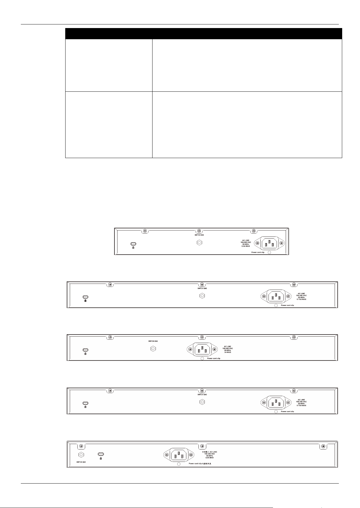
Rear Panel Components
On the rear panel of the Switch there are an AC power socket, an electrical grounding point, and a
security lock.
Figure 1-19 Rear panel view of a DGS-1510-20 Switch
Figure 1-20 Rear panel view of a DGS-1510-28 Switch
Figure 1-21 Rear panel view of a DGS-1510-28P Switch
Figure 1-22 Rear panel view of a DGS-1510-28X Switch
Figure 1-23 Rear panel view of a DGS-1510-28XMP Switch
DGS-1510 Series Gigabit Ethernet SmartPro Switch Hardware Installation Guide
14
Figure 1-24 Rear panel view of a DGS-1510-52 Switch
Figure 1-25 Rear panel view of a DGS-1510-52X (HW: A1) Switch
Figure 1-26 Rear panel view of a DGS-1510-52X (HW: A2) Switch
Figure 1-27 Rear panel view of a DGS-1510-52XMP Switch
The AC power connector is a standard three-pronged connector that supports the power cord. Plug-in
the female connector of the provided power cord into this socket, and the male side of the cord into a
power outlet. The Switch automatically adjusts the power setting to any supply voltage in the range
from 100 to 240 VAC at 50 to 60 Hz.
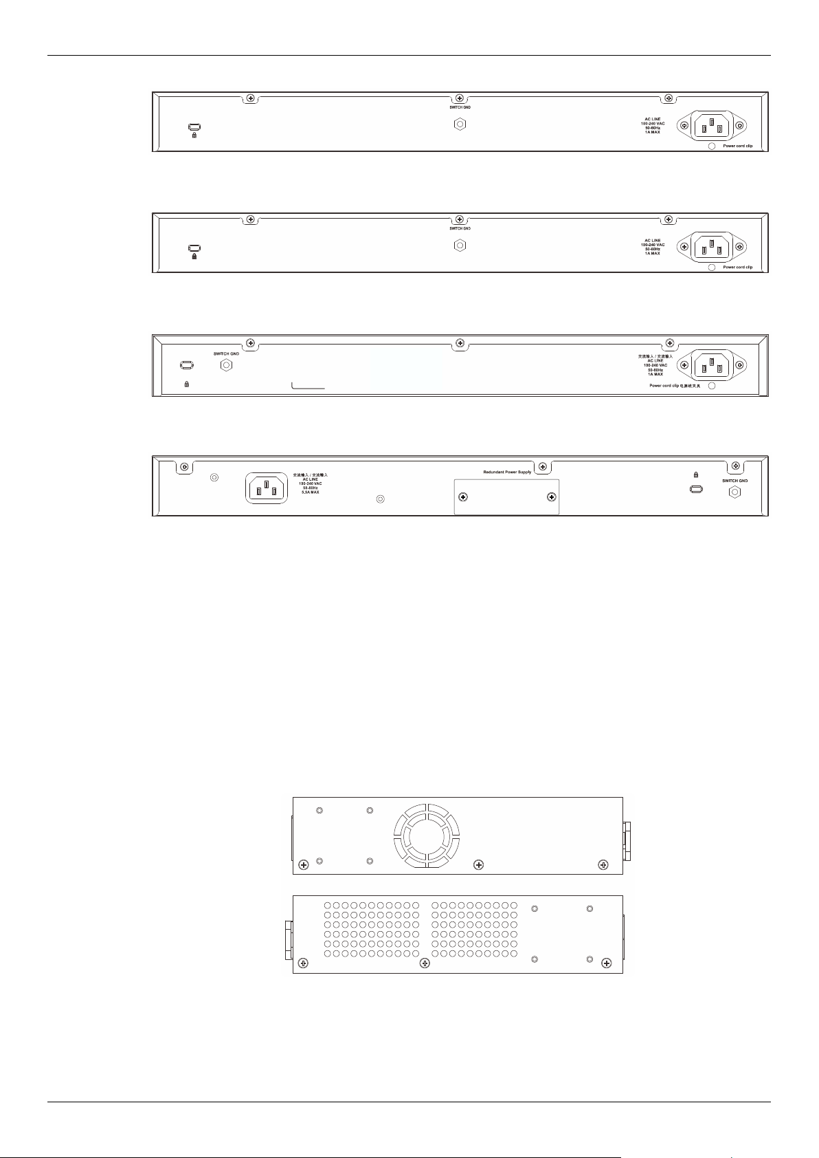
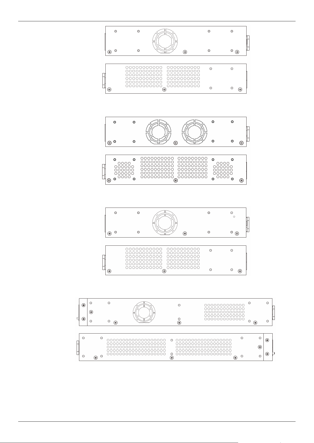
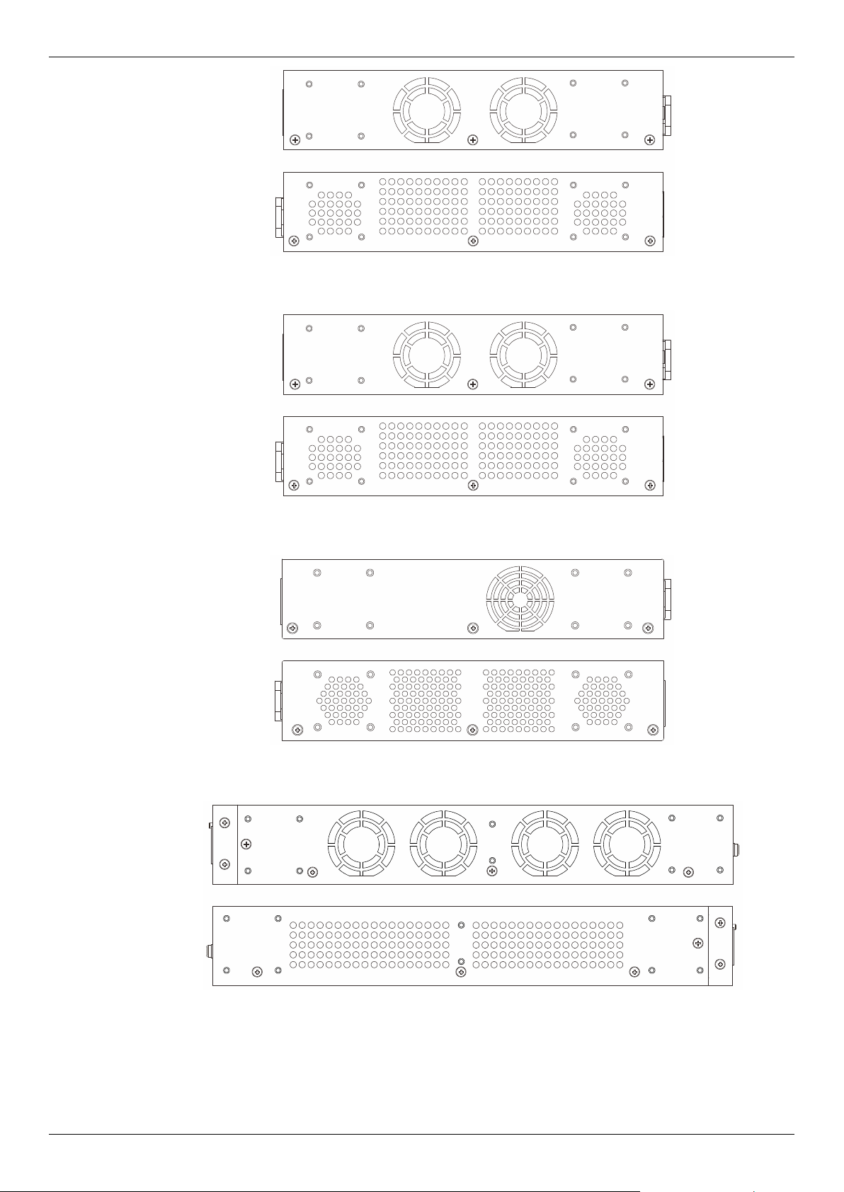
Side Panel Components
On the side panels of the Switch there are heat vents and fans to dissipate heat. Do not block these
openings. Leave at least 6 inches of space at the rear and sides of the Switch for proper ventilation.
Without proper heat dissipation and air circulation, system components might overheat which could
lead to system failure or even severely damaged components.
Figure 1-28 Side panels view of a DGS-1510-20 Switch
DGS-1510 Series Gigabit Ethernet SmartPro Switch Hardware Installation Guide
15
Figure 1-29 Side panels view of a DGS-1510-28 Switch
Figure 1-30 Side panels view of a DGS-1510-28P Switch
Figure 1-31 Side panels view of a DGS-1510-28X Switch
Figure 1-32 Side panels view of a DGS-1510-28XMP Switch
DGS-1510 Series Gigabit Ethernet SmartPro Switch Hardware Installation Guide
16
Figure 1-33 Side panels view of a DGS-1510-52 Switch
Figure 1-34 Side panels view of a DGS-1510-52X (HW: A1) Switch
Figure 1-35 Side panels view of a DGS-1510-52X (HW: A2) Switch
Figure 1-36 Side panels view of a DGS-1510-52XMP Switch
Smart Fans
The DGS-1510 Series Switches includes smart fans that will automatically change their speed
depending on the internal temperature detected by the sensors built-in the Switch’s hardware.

DGS-1510 Series Gigabit Ethernet SmartPro Switch Hardware Installation Guide
17
The following will explain at what temperature the speed of the fan(s) will change:
• DGS-1510-20: The fan speed will change from:
o Low Speed to High Speed at 48.0°C.
o High Speed to Low Speed at 43.0°C.
• DGS-1510-28: The fan speed will change from:
o Low Speed to High Speed at 48.0°C.
o High Speed to Low Speed at 43.0°C.
• DGS-1510-28P: The fan speed will change from:
o Low Speed to High Speed at 36.0°C.
o High Speed to Low Speed at 31.0°C.
• DGS-1510-28X: The fan speed will change from:
o Low Speed to High Speed at 48.0°C.
o High Speed to Low Speed at 43.0°C.
• DGS-1510-28XMP: The fan speed will change from:
o Low Speed to High Speed at 36.0°C.
o High Speed to Low Speed at 31.0°C.
• DGS-1510-52: The fan speed will change from:
o Low Speed to High Speed at 47.0°C.
o High Speed to Low Speed at 42.0°C.
• DGS-1510-52X (HW: A1): The fan speed will change from:
o Low Speed to High Speed at 47.0°C.
o High Speed to Low Speed at 42.0°C.
• DGS-1510-52X (HW: A2): The fan speed will change from:
o Low Speed to Medium Speed at 34.7°C. Medium Speed to High Speed at 44.7°C.
o High Speed to Medium Speed at 39.7°C. Medium Speed to Low Speed at 29.7°C.
• DGS-1510-52XMP: The fan speed will change from:
o Low Speed to Medium Speed at 34.7°C. Medium Speed to High Speed at 44.7°C.
o High Speed to Medium Speed at 39.7°C. Medium Speed to Low Speed at 29.7°C.
DGS-1510 Series Gigabit Ethernet SmartPro Switch Hardware Installation Guide
18
2. Installation
Installation Guidelines
Power On (AC Power)
Installation Guidelines
Please follow these guidelines for setting up the Switch:
• Install the Switch on a sturdy, level surface that can support at least 6 kg (13.2 lb). Do not place
heavy objects on the Switch.
• The power outlet should be within 1.82 meters (6 feet) of the Switch.
• Visually inspect the power cord and see that it is fully secured to the AC power port.
• Make sure that there is proper heat dissipation from and adequate ventilation around the
Switch. Leave at least 10 cm (4 inches) of space at the front and rear of the Switch for
ventilation.
• Install the Switch in a fairly cool and dry place for the acceptable temperature and humidity
operating ranges.
• Install the Switch in a site free from strong electromagnetic field generators (such as motors),
vibration, dust, and direct exposure to sunlight.
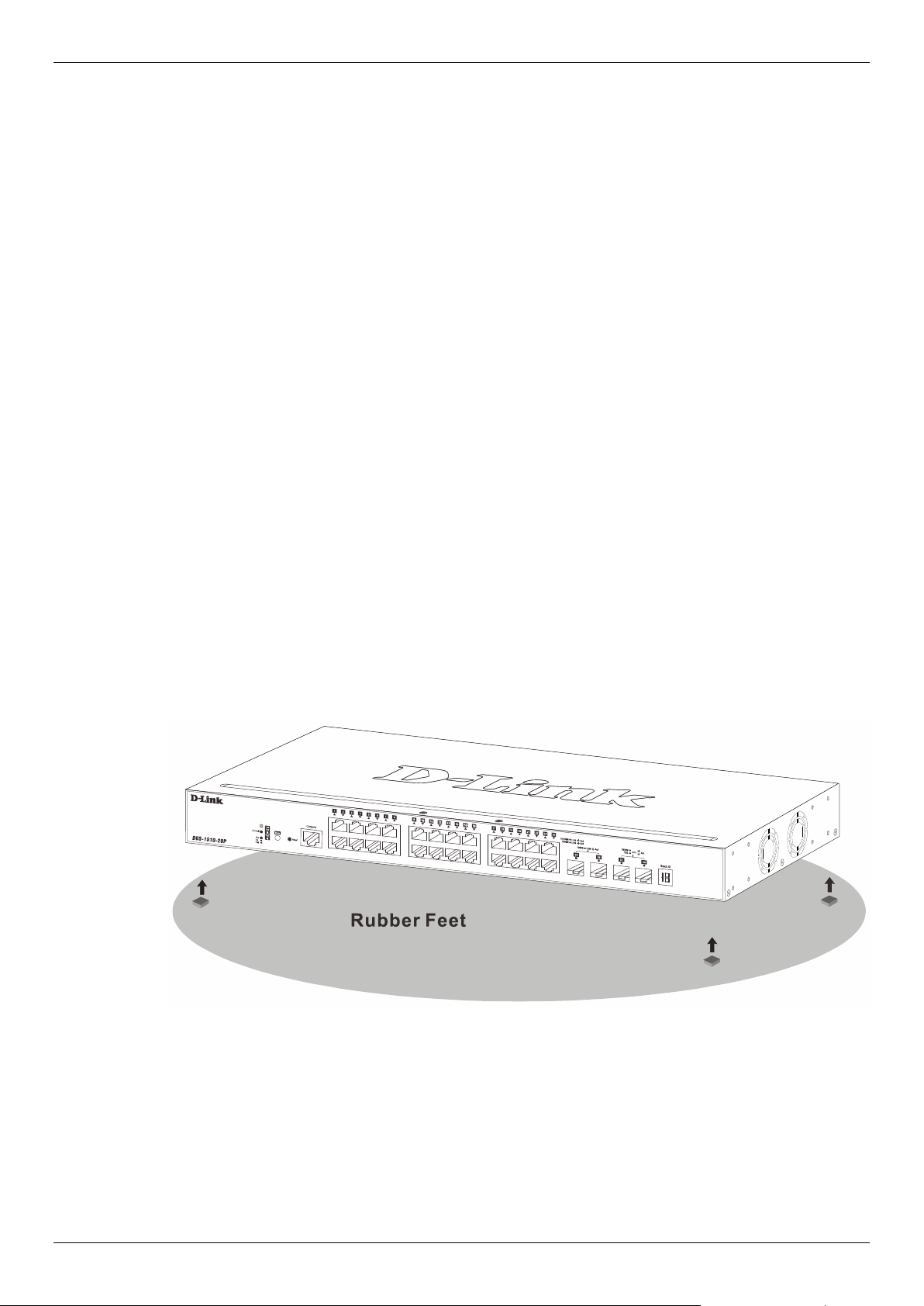
• When installing the Switch on a level surface, attach the rubber feet to the bottom of the device.
The rubber feet cushion the Switch, protect the casing from scratches and prevent it from
scratching other surfaces.
Installing the Switch without a Rack
First, attach the rubber feet included with the Switch if installing on a desktop or shelf. Attach these
cushioning feet on the bottom at each corner of the device. Allow enough ventilation space between
the Switch and any other objects in the vicinity.
Figure 2-1 Attach rubber feet to the Switch
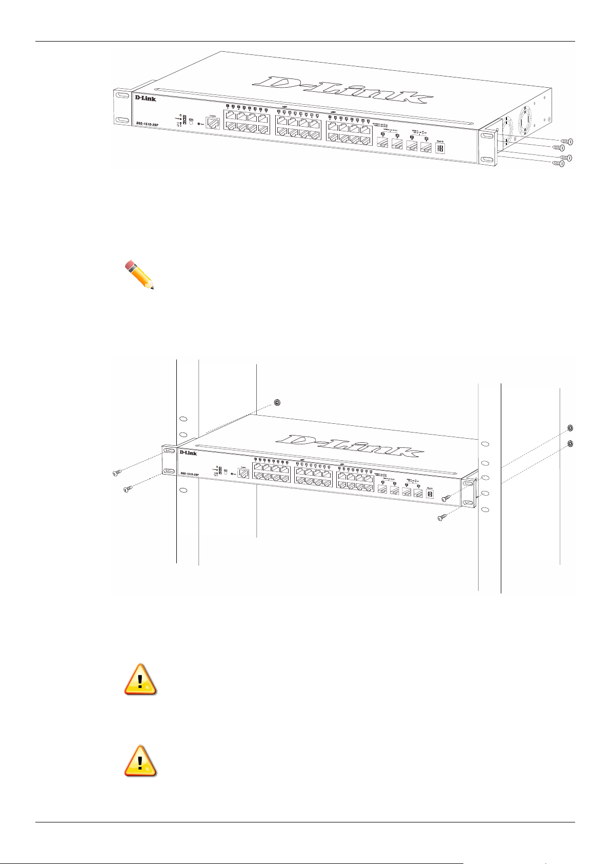
Attaching Brackets to a Switch for Rack Mounting
The Switch is mounted to a standard 19" rack using mounting brackets. Use the following diagrams
as a guide.
DGS-1510 Series Gigabit Ethernet SmartPro Switch Hardware Installation Guide
19
Figure 2-2 Attach mounting brackets to the Switch
Fasten the mounting brackets to the Switch using the screws provided. With the brackets attached
securely, the Switch can be mounted in a standard rack, as shown below.
NOTE: Please review the Installation Guidelines above before installing the Switch in
a rack. Make sure there is adequate space around the Switch to allow for
proper airflow, ventilation and cooling.
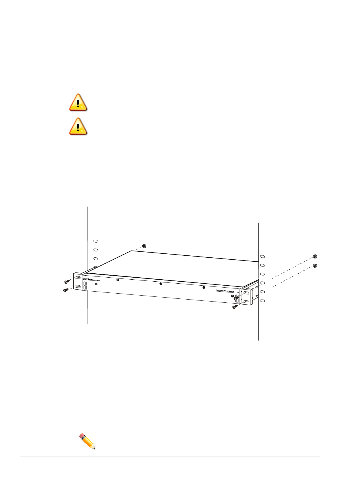
Installing the Switch in a Standard 19" Rack
Figure 2-3 Mount the Switch in a rack
CAUTION: Installing systems in a rack without the front and side stabilizers installed
could cause the rack to tip over, potentially resulting in bodily injury under
certain circumstances. Therefore, always install the stabilizers before
installing components in the rack. After installing components in a rack, do
not pull more than one component out of the rack on its slide assemblies
at one time. The weight of more than one extended component could
cause the rack to tip over and may result in injury.
ATTENTION: Le montage de systèmes sur un rack dépourvu de pieds stabilisateurs
avant et latéraux peut faire basculer le rack, pouvant causer des
dommages corporels dans certains cas. Par conséquent, installez toujours
les pieds stabilisateurs avant de monter des composants sur le rack.
Après l'installation de composants dans un rack, ne sortez pas plus d'un
composant à la fois hors du rack sur ses glissières. Le poids de plusieurs
DGS-1510 Series Gigabit Ethernet SmartPro Switch Hardware Installation Guide
20
composants sur les glissières en extension peut faire basculer le rack,
pouvant causer des blessures.
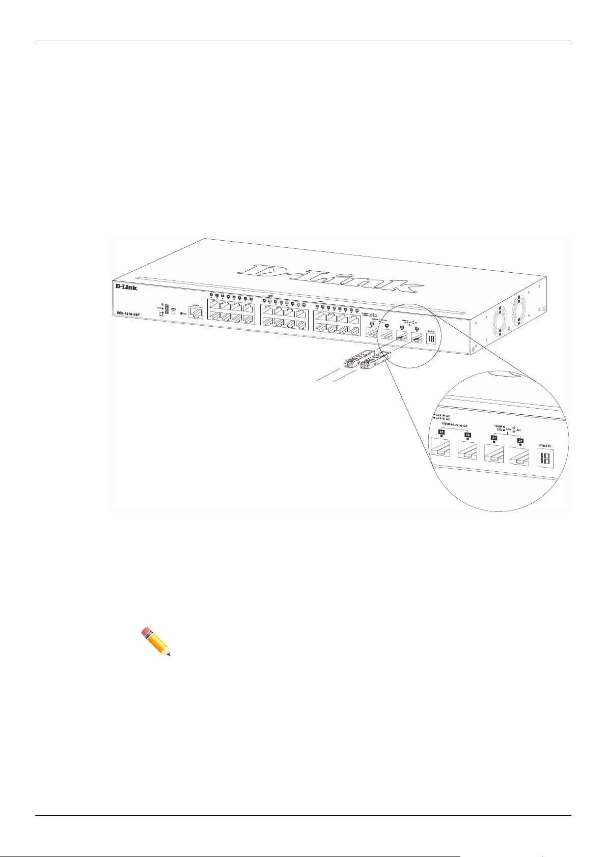
Installing Transceivers into the Transceiver Ports
The Switch is equipped with SFP (Small Form Factor Portable) and SFP+ ports, which are used with
fiber-optical transceiver cabling. SFP ports support full-duplex transmissions, auto-negotiation, and
can be uplinked with various other switches across a gigabit network. The SFP ports support data
rates of up to 1Gbit/s and the SFP+ ports support data rates of up to 10Gbit/s.
See the figure below for installing the transceiver in the transceiver port on the Switch.
Figure 2-4 Inserting fiber-optic transceivers into a Switch
For a full list of supported transceivers, compatible with this switch series, refer to Port Functions.
NOTE: Only use pluggable optical modules and Direct-Attach Cables (DAC) that
meet the following regulatory requirements:
• Class 1 Laser Product
• UL and/or CSA registered component for North America
• FCC 21 CFR Chapter 1, Sub-chapter J in accordance with FDA & CDRH
requirements
• IEC/EN 60825-1/-2: 2007 2nd edition or later, European Standard
Power On (AC Power)
Plug one end of the AC power cord into the power socket of the Switch and the other end into the
local power source outlet. After the system powered on, the LED’s blink green to indicate that the
system is booting up.
DGS-1510 Series Gigabit Ethernet SmartPro Switch Hardware Installation Guide
21
Power Failure (AC Power)
In the event of a power failure, just as a precaution, unplug the power cord from the Switch. After the
power returns, plug the power cord back into the power socket of the Switch.
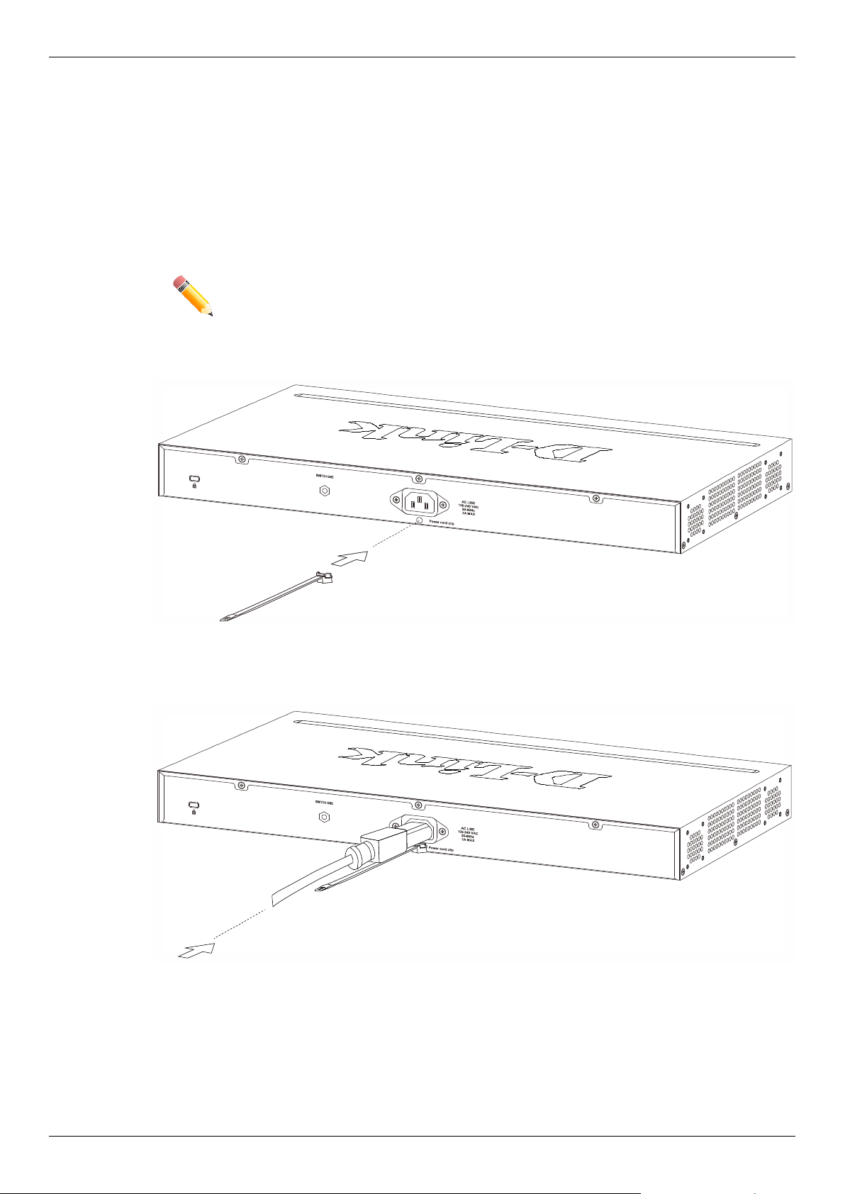
Installing Power Cord Clip
To prevent accidental removal of the AC power cord, it is recommended to install the power cord clip
together with the power cord.
NOTE: The DGS-1510-52XMP does not support the installation of the power cord clip.
With the rough side facing down, insert the Tie Wrap into the hole below the power socket.
Figure 2-5 Insert Tie Wrap to the Switch
Plug the AC power cord into the power socket of the Switch.
Figure 2-6 Connect the power cord to the Switch

DGS-1510 Series Gigabit Ethernet SmartPro Switch Hardware Installation Guide
22
Slide the Retainer through the Tie Wrap until the end of the cord.
Figure 2-7 Slide the Retainer through the Tie Wrap
Circle the tie of the Retainer around the power cord and into the locker of the Retainer.
Figure 2-8 Circle around the power cord

DGS-1510 Series Gigabit Ethernet SmartPro Switch Hardware Installation Guide
23
Fasten the tie of the Retainer until the power cord is secured.
Figure 2-9 Secure the power cord
DGS-1510 Series Gigabit Ethernet SmartPro Switch Hardware Installation Guide
24
Installing the RPS into a Rack-mount Chassis
The DPS-700 is a redundant power supply unit designed to conform to the voltage requirements of
the switches being supported.
The DPS-700 can only be used with the DGS-1510-52XMP.
CAUTION: DO NOT connect the RPS to AC power before the DC power cable is
connected. This might damage the internal power supply.
ATTENTION: Ne branchez pas le RPS sur le courant alternatif avant que le câble
d'alimentation en courant continu ne soit branché. Cela pourrait
endommager l'alimentation électrique interne.
DPS-700
The DPS-700 is connected to the Master Switch using a 22-pin DC power cable. A standard, three-
pronged AC power cable connects the redundant power supply to the main power source.
Figure 2-10 Front view of the DPS-700
1. Insert one end of the 22-pin DC power cable into the receptacle on the Switch and the other end
into the Redundant Power Supply unit.
2. Using a standard AC power cable, connect the redundant power supply to the main AC power
source. A green LED on the front of the DPS-700 will glow to indicate a successful connection.
3. Re-connect the Switch to the AC power source. The LED indicator will show that a redundant
power supply is now in operation.
4. No configuration in the Switch’s firmware is needed for this installation.
NOTE: See the RPS Quick Installation Guide for more information.
DGS-1510 Series Gigabit Ethernet SmartPro Switch Hardware Installation Guide
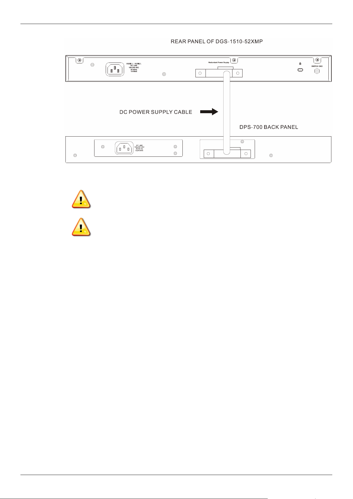
25
Figure 2-11 Rear view of the DPS-700 connected to a DGS-1510-52XMP
CAUTION: Do not connect the DPS-700 to the DGS-1510-52XMP by using the 14-pin
DC power cable. It may cause damage when using the wrong DC power
cable. ONLY use the 22-pin DC power cable.
ATTENTION: Ne connectez pas le DPS-700 au DGS-1510-52XMP en utilisant le câble
d'alimentation CC à 14 broches. Cela pourrait causer des dommages en
utilisant le mauvais câble d'alimentation CC. Utilisez UNIQUEMENT le
câble d'alimentation CC à 22 broches.
DGS-1510 Series Gigabit Ethernet SmartPro Switch Hardware Installation Guide
26
3. Connecting the Switch
Switch to End Node
Switch to another Switch
Switch to a Server
Switch to End Node
An End Node can be any networking device, plugged into any of the networking ports of the Switch,
where data transmission ends. Typical end nodes are computers. End nodes are generally outfitted
with a 10/100/1000Mbps RJ-45 Ethernet Network Interface Card (NIC) that can connect to the Switch
via a twisted-pair UTP/STP cable. Connect the end node to any of the copper ports of the Switch. The
Link/Act LEDs for each Ethernet port turns green or amber when the link is active. A blinking LED
indicates packet activity on that port.
Figure 3-1 End Node to Switch Connection
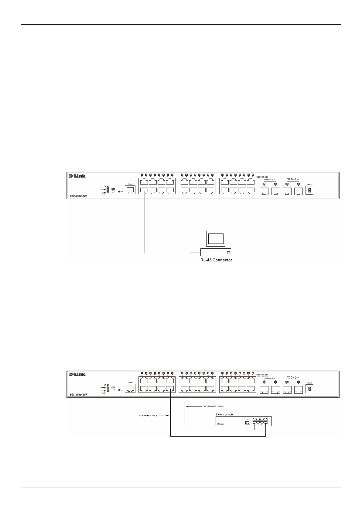
Switch to another Switch
There is a great deal of flexibility on how connections are made using the appropriate cabling.
• Connect a 10BASE-T switch port to the Switch via a twisted-pair Category 3, 4 or 5 UTP/STP
cable.
• Connect a 100BASE-TX switch port to the Switch via a twisted-pair Category 5 UTP/STP cable.
• Connect 1000BASE-T switch port to the Switch via a twisted pair Category 5e UTP/STP cable.
• Connect switch supporting a fiber-optic uplink to the Switch’s SFP ports via fiber-optic cabling.
Figure 3-2 Switch to Switch Connection
DGS-1510 Series Gigabit Ethernet SmartPro Switch Hardware Installation Guide
27
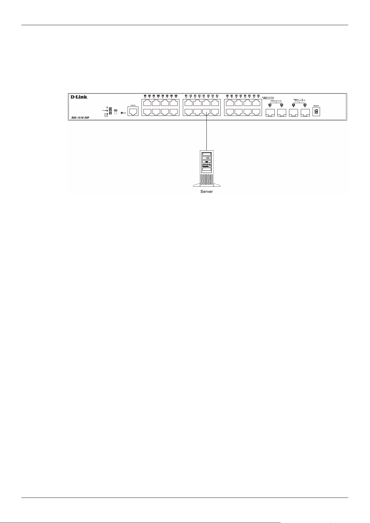
Switch to a Server
The Combo Copper/SFP ports are ideal for connecting a network backbone, server or server farm to
the Switch. The copper ports operate at a speed of 10/100/1000Mbps in half-duplex or full-duplex
mode. The fiber-optic ports can operate at both 100/1000Mbps in full-duplex mode. The Link LED
turns green when a connection is made.
Figure 3-3 Server to Switch Connection

DGS-1510 Series Gigabit Ethernet SmartPro Switch Hardware Installation Guide
28
4. Introduction to Switch Management
Management Options
Connecting the Console Port
SNMP Settings
Management Options
This Switch can be managed, out-of-band, through the console port on the front panel or in-band
using Telnet. Alternatively, the web-based management can be used, accessible through a web
browser.
Command Line Interface (CLI) Management
The user can connect a computer or terminal to the serial console port to access the Switch. The
Command Line Interface (CLI) provides complete access to all Switch management features. When
connecting to the Switch by means of Telnet or SSH, the same CLI can be accessed for Switch
management. For more detailed information about the CLI, refer to the CLI Reference Guide.
SNMP-based Management
The Switch can also be managed with an SNMP-compatible console program. The Switch supports
SNMPv1, SNMPv2c, and SNMPv3. The SNMP agent decodes the incoming SNMP messages and
responds to requests with MIB objects stored in the database. The SNMP agent updates the MIB
objects to generate statistics and counters.
Web-based User Interface (Web UI) Management
The user can connect a computer to any one of the frontal ports of the Switch, other than the console
port, to access the Web UI of the Switch by means of a Web browser and entering the IP address of
the Switch. This management interface is a more graphically representation of the features that can
be viewed and configured on this Switch. Most of the features available from the CLI can be accessed
through the Web UI. Web browsers like Microsoft’s Internet Explorer, Mozilla Firefox or Google
Chrome can be used. For more detailed information about the Web UI, refer to the Web UI Reference
Guide.
Connecting the Console Port
This section describes how to access the CLI through the serial port. To connect to the serial port, a
special Console Cable must be used. This cable is included with this product’s packaging. The cable
referred to as an RS-232 to RJ-45 connector cable specifically pinned to connect to this switch’s serial
port by using the correct pin configuration.
For more information about the pin layout of this cable, refer to Appendix B.
To connect to the console port of the Switch, use the following steps:
• Connect the RS-232 end of the console cable to the Serial Port of the management PC.
• Connect the RJ-45 end of the console cable to the Console Port of the Switch.
• Open the HyperTerminal application (or any terminal emulation program capable of emulating
a VT-100 terminal connection) on the management PC and configure the Properties of this
connection.
o The Bits per second should be 115200 baud.
o The Data bits should be 8.
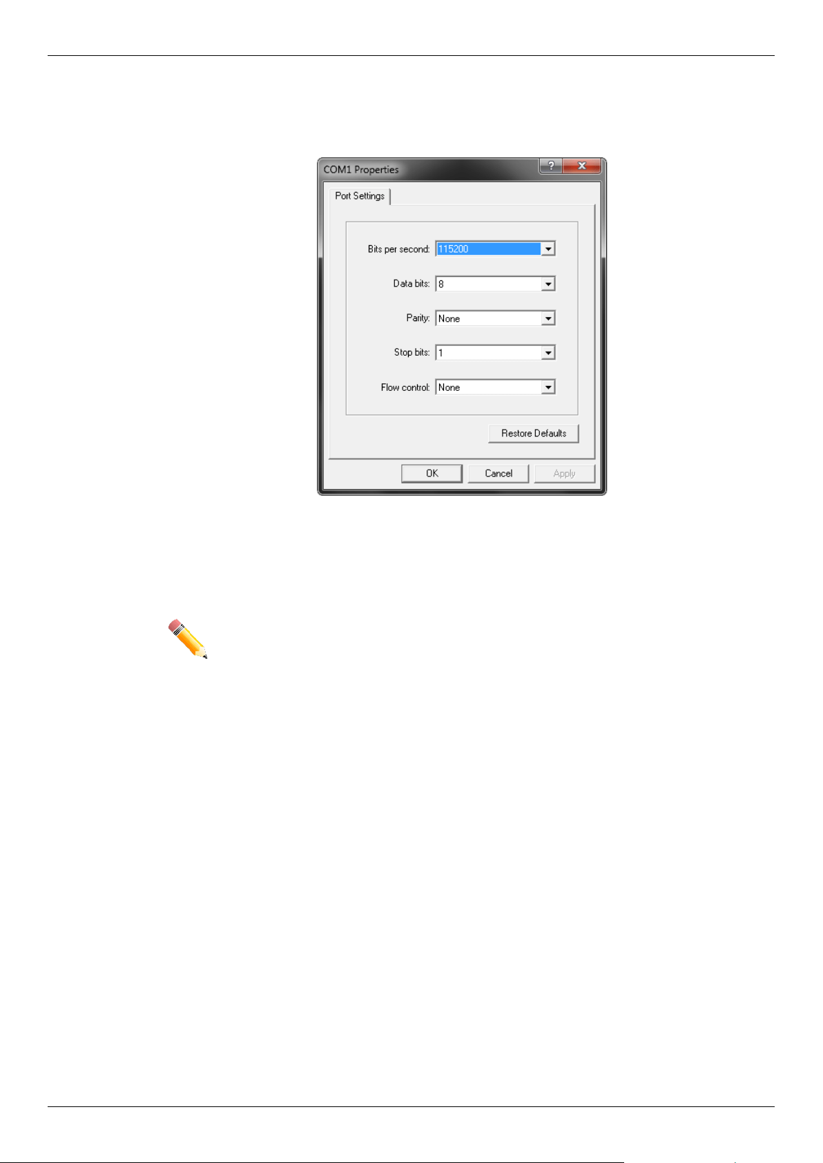
DGS-1510 Series Gigabit Ethernet SmartPro Switch Hardware Installation Guide
29
o The Parity should be None.
o The Stop bits should be 1.
o The Flow control should be None.
Figure 4-1 HyperTerminal Connection Properties
• Now the Switch can be turned on and access to the Switch’s CLI will be available.
NOTE: Access to the console port can be made at any time while the Switch is on.
There is no need to turn the Switch off when plugging the console cable into
the console port.

DGS-1510 Series Gigabit Ethernet SmartPro Switch Hardware Installation Guide
30
Connecting to the Switch for the First Time
After successfully connecting to the Switch’s console and the Switch was turned on, the boot-up
procedure will be displayed, as shown below.
Boot Procedure V1.00.016
-------------------------------------------------------------------------------
Power On Self Test ........................................ 100 %
MAC Address : 3C-1E-04-A1-B9-E0
H/W Version : A1
Please Wait, Loading V1.70.005 Runtime Image .............. 100 %
UART init ................................................. 100 %
Starting runtime image
Device Discovery .......................................... 100 %
Configuration init ........................................ 100 %
Switch con0 is now available
Press any key to login...
During the boot-up procedure, we can find the PROM version, MAC address, Hardware Version, and
Firmware Version used by this Switch.
NOTE: Both the default username and password is admin.
Enter the username and password when prompt to do so and press enter after each entry. The CLI
prompt will immediately be available, as shown below.
DGS-1510-28XMP Gigabit Ethernet SmartPro Switch
Command Line Interface
Firmware: Build 1.70.005
Copyright(C) 2020 D-Link Corporation. All rights reserved.
User Access Verification
Username:admin
Password:*****
Switch#
Now the Switch can be configured.

DGS-1510 Series Gigabit Ethernet SmartPro Switch Hardware Installation Guide
31
CAUTION: For security reasons, it is highly recommended to configure a personal
username and password for this Switch.
ATTENTION: Pour des raisons de sécurité, il est fortement recommandé de configurer
un nom d'utilisateur et un mot de passe personnels pour ce commutateur.
Creating a User Account
This section will discuss how to create a login username and password on this Switch. This login
details will be applied not only for access to the CLI, but also for access to the Web UI, Telnet, SSH,
and SSL interfaces. The same username and password will be used for these connections.
To create a user account, enter the following commands.
Switch> enable
Switch# configure terminal
Switch(config)# username Administrator password 12345
Switch(config)# username Administrator privilege 15
Switch(config)# line console
Switch(config-line)# login local
Switch(config-line)#
In the above example,
• We accessed the Privileged EXEC Mode by entering the command enable.
• Then we entered the Global Configuration Mode by entering the command configure
terminal.
• Then we created a user account with the username of ‘Administrator’ and gave it the
password of ‘12345’ by entering the command username Administrator password 12345.
• Then we assigned the privilege level of 15 to this user account by entering the command
username Administrator privilege 15. The highest level access is 15 and the lowest level
access is 1.
• Then we entered the LINE Configuration Mode by entering the command line console.
• Then we configured the Switch to allow access to the management interface by using locally
configured user accounts. The command is login local.
NOTE: CLI configuration commands only modify the running configuration file and are
not saved when the Switch is rebooted. To save all your configuration changes
in non-volatile storage, you must use the copy running-configuration start-
up-configuration command to copy the running configuration file to the start-
up configuration. For more information, refer to the CLI Reference Guide.
Configuring the IP Address
Each networking node, within a network, must use a unique IP Address. This IP address is used to
communicate with other networking devices in the network. The IP address of the Switch is also
important to be able to access the Web UI of this Switch.

DGS-1510 Series Gigabit Ethernet SmartPro Switch Hardware Installation Guide
32
There are two methods in which a Switch can obtain an IP address.
• The Switch can obtain an IP address from a DHCP server located within the local network. By
default, this option is not enabled.
• The administrator can manually configure an IP address for this Switch.
To find out what the IP address of the Switch is, we again need to access the Switch management
interface through the CLI. Take note of the following example.
Switch> show ip interface
Interface vlan1 is enabled, Link status is down
IP Address is 10.90.90.90/8 (Manual)
ARP timeout is 20 minutes.
Proxy ARP is disabled
IP Local Proxy ARP is disabled
gratuitous-send is disabled, interval is 0 seconds
Total Entries: 1
Switch>
In the above example, the command show ip interface is used to display information about the IP
interfaces created on this Switch. In this display we see that the IP address for this switch is
10.90.90.90 and the CIDR notation for the subnet mask is /8 which translates to 255.0.0.0. This
information can however be modified, as show below.
Switch> enable
Switch# configure terminal
Switch(config)# interface vlan 1
Switch(config-if)# ip address 192.168.1.1 255.255.255.0
Switch(config-if)#
In the above example,
• We accessed the Privileged EXEC Mode by entering the command enable.
• Then we entered the Global Configuration Mode by entering the command configure
terminal.
• Then we entered the VLAN Configuration Mode of the default VLAN, which is VLAN 1, by
entering the command interface vlan 1.
• Then we changed the IP address of the Switch to 192.168.1.1 and the subnet mask to
255.255.255.0 by entering the command ip address 192.168.1.1 255.255.255.0.
SNMP Settings
The Simple Network Management Protocol (SNMP) is an OSI Layer 7 (Application Layer) designed
specifically for managing and monitoring network devices. SNMP enables network management
stations to read and modify the settings of gateways, routers, switches and other network devices.
Use SNMP to configure system features for proper operation, monitor performance and detect
potential problems in the Switch, switch group or network.
Managed devices that support SNMP include software (referred to as an agent), which runs locally on
the device. A defined set of variables (managed objects) is maintained by the SNMP agent and used
to manage the device. These objects are defined in a Management Information Base (MIB), which
provides a standard presentation of the information controlled by the on-board SNMP agent. SNMP
defines both the format of the MIB specifications and the protocol used to access this information over
the network.

DGS-1510 Series Gigabit Ethernet SmartPro Switch Hardware Installation Guide
33
The Switch supports SNMPv1, SNMPv2c, and SNMPv3. The administrator may specify which SNMP
version to use to monitor and control the Switch. The three SNMP versions vary in the level of security
provided between the management station and the network device.
In SNMPv1 and SNMPv2, user authentication is accomplished using 'community strings', which
function like passwords. The remote user SNMP application and the Switch SNMP must use the
same community string. SNMP packets from any station that has not been authenticated are ignored
(dropped).
The default community strings for the Switch used for SNMPv1 and SNMPv2 management access
are:
• public - Allows authorized management stations to retrieve MIB objects.
• private - Allows authorized management stations to retrieve and modify MIB objects.
SNMPv3 uses a more sophisticated authentication process that is separated into two parts. The first
part is to maintain a list of users and their attributes that are allowed to act as SNMP managers. The
second part describes what each user on that list can do as an SNMP manager.
The Switch allows groups of users to be listed and configured with a shared set of privileges. The
SNMP version may also be set for a listed group of SNMP managers. Thus, a group of SNMP
managers can be created to view read-only information or receive traps using SNMPv1 while
assigning a higher level of security to another group, granting read/write privileges using SNMPv3.
Using SNMPv3 individual users or groups of SNMP managers can be allowed to perform or be
restricted from performing specific SNMP management functions. The functions allowed or restricted
are defined using the Object Identifier (OID) associated with a specific MIB. An additional layer of
security is available for SNMPv3 in that SNMP messages may be encrypted.
Traps
Traps are messages that alert network personnel of events that occur on the Switch. The events can
be as serious as a reboot (someone accidentally turned OFF the Switch), or less serious like a port
status change. The Switch generates traps and sends them to the trap recipient (or network
manager). Typical traps include trap messages for Authentication Failure, Topology Change and
Broadcast\Multicast Storm.
Management Information Base (MIB)
The Switch in the Management Information Base (MIB) stores management and counter information.
The Switch uses the standard MIB-II Management Information Base module. Consequently, values
for MIB objects can be retrieved from any SNMP-based network management software. In addition to
the standard MIB-II, the Switch also supports its own proprietary enterprise MIB as an extended
Management Information Base. The proprietary MIB may also be retrieved by specifying the MIB
Object Identifier. MIB values can be either read-only or read-write.
NOTE: For customers interested in D-View, D-Link Corporation's proprietary SNMP
management software, go to http://dview.dlink.com.tw/
and
download the
software and manual.
DGS-1510 Series Gigabit Ethernet SmartPro Switch Hardware Installation Guide
34
5. Web-based Switch Configuration
Introduction
Logging onto the Web Manager
Web-based User Interface
Introduction
Most software functions of the Switch can be managed, configured, and monitored via the embedded
Web User Interface (Web UI). Manage the Switch from remote stations anywhere on the network
through a standard browser, such as Internet Explorer (version 7 and later), Mozilla Firefox, Chrome,
or Safari. The browser acts as a universal access tool and can communicate directly with the Switch
using the HTTP protocol.
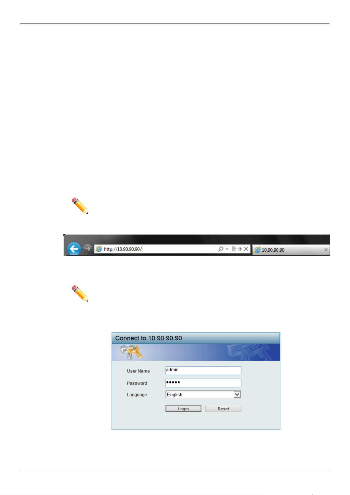
Logging onto the Web Manager
To access the Web UI, simply open a standard web browser on the management PC, enter the
Switch’s default IP address into the address bar of the browser and press the Enter key.
NOTE: The default IP address of this switch is 10.90.90.90, with a subnet mask of
255.0.0.0.
Figure 5-1 IP address in Internet Explorer
NOTE: The default username is admin and the default password is admin.
This will open the user authentication window, as seen below.
Figure 5-2 Enter Network Password Window
Enter the User Name and Password in the corresponding fields and click Login. This will open the
Web UI. Management features available in the Web UI of the Switch are explained below.
DGS-1510 Series Gigabit Ethernet SmartPro Switch Hardware Installation Guide
35
Web-based User Interface
The user interface provides access to various Switch configuration and management windows, it
allows the user to view performance statistics, and permits graphical monitoring of the system status.
Areas of the User Interface
The Web UI on the Switch can be divided into distinct Areas. Different areas in the Web UI provide
different manageability options to simplify configuration and feature monitoring.
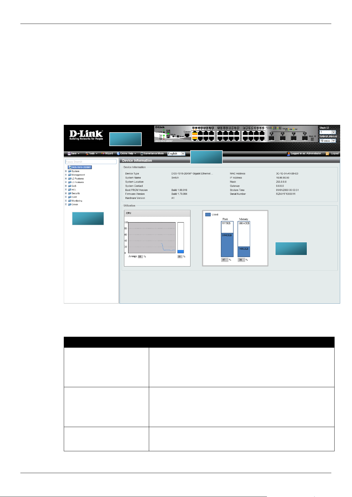
After accessing the Web UI in the Standard Mode, the following will be displayed:
Figure 5-3 Web UI (Standard Mode)
The following Areas can be observed in the above window.
Area Number Description
AREA 1 In this area, a graphical near real-time image of the front panel of the
Switch is displayed with ports and expansion modules. Port activity is
displayed, depending on the specified mode. Some management
functions like port monitoring are also accessible here.
Click the D-Link logo to go to the D-Link website.
AREA 2
In this area is a toolbar used to access functions like Save, Tools,
the Wizard, Online Help, accessing the Web UI in the Surveillance
Mode, customized Language preference, and a Logout option.
The user account and IP address currently logged into the Web UI
will also be displayed in this toolbar.
AREA 3 In this area, the software features available in the Web UI of the
Switch are grouped into folders containing hyperlinks that will open
window frames in area 4.
AREA 1
AREA 3
AREA 4
AREA 2
DGS-1510 Series Gigabit Ethernet SmartPro Switch Hardware Installation Guide
36
Area Number Description
There is also a search option in this area that can be used to search
for specific feature keywords in the Web UI to easily find the link to
the set of features.
AREA 4 In this area, configuration and monitoring window frames are
available based on the selections made in area 3.
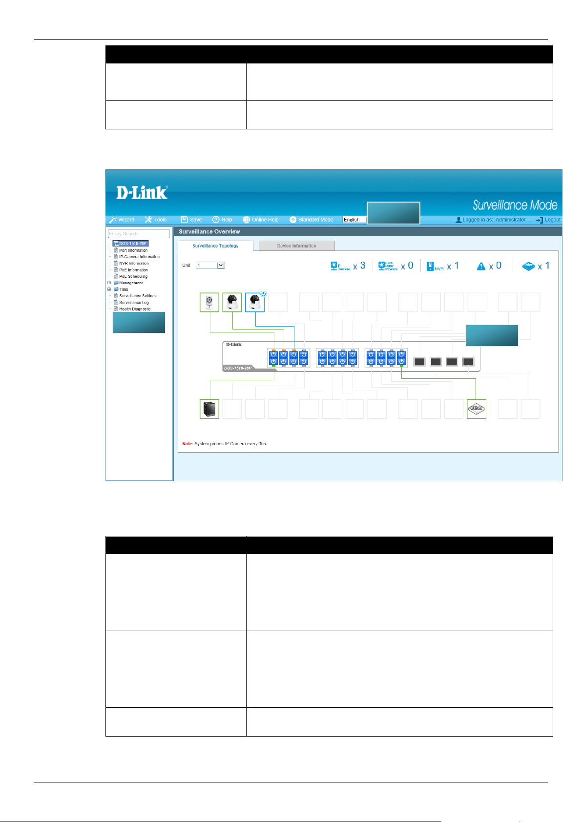
After accessing the Web UI in the Surveillance Mode, the following will be displayed:
Figure 5-4 Web UI (Surveillance Mode)
The following Areas can be observed in the above window.
Area Number Description
AREA 1
In this area is a toolbar used to access functions like the Wizard,
Tools, Save, Help, Online Help, accessing the Web UI in the
Standard Mode, customized Language preference, and a Logout
option.
The user account and IP address currently logged into the Web UI
will also be displayed in this toolbar.
AREA 2 In this area, the software features available in the Web UI of the
Switch are grouped into folders containing hyperlinks that will open
window frames in area 3.
There is also a search option in this area that can be used to search
for specific feature keywords in the Web UI to easily find the link to
the set of features.
AREA 3 In this area, configuration and monitoring window frames are
available based on the selections made in area 2.
AREA 1
AREA 2
AREA 3

DGS-1510 Series Gigabit Ethernet SmartPro Switch Hardware Installation Guide
37
Appendix A – Technical Specifications
General
Feature Detailed Description
Standards IEEE 802.1AB Link Layer Discovery Protocol
IEEE 802.1D-2004 Spanning Tree Protocol
IEEE 802.1p Priority Queues
IEEE 802.1Q-2005 Virtual LAN
IEEE 802.1S Multiple Spanning Tree Protocol
IEEE 802.1W Rapid Spanning Tree Protocol
IEEE 802.1X Port-based Authentication
IEEE 802.3i 10BASE-T Ethernet
IEEE 802.3u 100BASE-TX Fast Ethernet
IEEE 802.3ab 1000BASE-T Gigabit Ethernet
IEEE 802.3ad Link Aggregation
IEEE 802.3ae 10GBASE-X/10GBASE-R/10GBASE-W
IEEE 802.3af Power over Ethernet
IEEE 802.3at Power over Ethernet
IEEE 802.1az Energy-Efficient Ethernet
IEEE 802.3x Flow Control support for Full-Duplex mode
IEEE 802.3z 1000BASE-T Gigabit Ethernet
Data Transfer Rates Half-duplex Full-duplex
Ethernet 10 Mbps 20 Mbps
Fast Ethernet 100 Mbps 200 Mbps
Gigabit Ethernet - 2 Gbps
10 Gigabit Ethernet - 20 Gbps
Stacking Topology Duplex Ring, Duplex Chain
Network Cables UTP/STP Category 3, 4, 5 for 10BASE-T
UTP/STP Category 5 Enhanced for 1000BASE-T
UTP/STP Category.5, 5 Enhanced for 100BASE-TX
EIA/TIA-568 100Ω screened twisted-pair (STP) (100m)
Physical and Environmental
Feature Detailed Description
Internal Power Supply DGS-1510-20: 100-240 VAC, 50/60 Hz, 24 Watt
DGS-1510-28: 100-240 VAC, 50/60 Hz, 30 Watt
DGS-1510-28P: 100-240 VAC, 50/60 Hz, 253 Watt
DGS-1510-28X: 100-240 VAC, 50/60 Hz, 30 Watt
DGS-1510-28XMP: 100-240 VAC, 50/60 Hz, 430 Watt
DGS-1510-52: 100-240 VAC, 50/60 Hz, 54 Watt
DGS-1510-52X
(HW: A1):
100-240 VAC, 50/60 Hz, 54 Watt

DGS-1510 Series Gigabit Ethernet SmartPro Switch Hardware Installation Guide
38
Feature Detailed Description
DGS-1510-52X
(HW: A2):
100-240 VAC, 50/60 Hz, 54 Watt
DGS-1510-52XMP: 100-240 VAC, 50/60 Hz, 589 Watt
Fans The IC Sensor detects the temperature on the switch automatically,
and adjusts the speed. The amount of fans that are installed per
Switch are listed below:
DGS-1510-20: 1 fan
DGS-1510-28: 1 fan
DGS-1510-28P: 2 fans
DGS-1510-28X: 1 fan
DGS-1510-28XMP: 2 fans
DGS-1510-52: 2 fans
DGS-1510-52X
(HW: A1):
2 fans
DGS-1510-52X
(HW: A2):
1 fan
DGS-1510-52XMP: 4 fans
Maximum Power
Consumption
DGS-1510-20: 20.3 Watt
DGS-1510-28: 21.2 Watt
DGS-1510-28P: 29.0 Watt (PoE off) and 238.7 Watt (PoE on)
DGS-1510-28X: 22.3 Watt
DGS-1510-28XMP: 38.4 Watt (PoE off) and 436.3 Watt (PoE on)
DGS-1510-52: 38.4 Watt
DGS-1510-52X
(HW: A1):
44.22 Watt
DGS-1510-52X
(HW: A2):
48 Watt
DGS-1510-52XMP: 53.9 Watt (PoE off) and 468.6 Watt (PoE on)
Standby Power
Consumption
DGS-1510-20: 11.4 Watt (100V) and 12.2 Watt (240V)
DGS-1510-28: 14.6 Watt (100V) and 15.2 Watt (240V)
DGS-1510-28P: 22.7 Watt (100V) and 21.0 Watt (240V)
DGS-1510-28X: 14.6 Watt (100V) and 15.2 Watt (240V)
DGS-1510-28XMP: 24.5 Watt (100V) and 28.2 Watt (240V)
DGS-1510-52: 27.3 Watt (100V) and 27.6 Watt (240V)
DGS-1510-52X
(HW: A1):
28.6 Watt (100V) and 28.9 Watt (240V)
DGS-1510-52X
(HW: A2):
30.4 Watt (100V) and 30.3 Watt (240V)
DGS-1510-52XMP: 38.0 Watt (100V) and 38.6 Watt (240V)
Temperature Operating: -5 °C ~ 50 °C (23 °F ~ 122 °F)
Storage: -20 °C ~ 70 °C (-4 °F ~ 158 °F)
Humidity Operating: 0 % ~ 95 % (non-condensing)
Storage: 0 % ~ 95 % (non-condensing)

DGS-1510 Series Gigabit Ethernet SmartPro Switch Hardware Installation Guide
39
Feature Detailed Description
Dimensions DGS-1510-20: 280 mm (W) 180 mm (D) 44 mm (H)
DGS-1510-28: 441 mm (W) 210 mm (D) 44 mm (H)
DGS-1510-28P: 441 mm (W) 210 mm (D) 44 mm (H)
DGS-1510-28X: 441 mm (W) 210mm (D) 44mm (H)
DGS-1510-28XMP: 441 mm (W) 310 mm (D) 44 mm (H)
DGS-1510-52: 441 mm (W) 210 mm (D) 44 mm (H)
DGS-1510-52X
(HW: A1):
441 mm (W) 210 mm (D) 44 mm (H)
DGS-1510-52X
(HW: A2):
441 mm (W) 210 mm (D) 44 mm (H)
DGS-1510-52XMP: 441 mm (W) 309 mm (D) 44 mm (H)
Weight DGS-1510-20: 1.235 kg
DGS-1510-28: 2.000 kg
DGS-1510-28P: 2.536 kg
DGS-1510-28X: 2.000 kg
DGS-1510-28XMP: 4.246 kg
DGS-1510-52: 2.400 kg
DGS-1510-52X
(HW: A1):
2.397 kg
DGS-1510-52X
(HW: A2):
3.1 kg
DGS-1510-52XMP: 5.41 kg
MTBF DGS-1510-20: 882152.3682 hours
DGS-1510-28: 516593.2513 hours
DGS-1510-28P: 243090.6950 hours
DGS-1510-28X: 516593.2513 hours
DGS-1510-28XMP: 274796.3861 hours
DGS-1510-52: 433434.1606 hours
DGS-1510-52X
(HW: A1):
416789.0227 hours
DGS-1510-52X
(HW: A2):
423302.2461 hours
DGS-1510-52XMP: 195178.1349 hours
EMI/EMC; Test Reports CE Class A, FCC Class A, VCCI Report Class A, C-Tick Report
Class A, BSMI, CCC.
Safety Certifications and
Test Reports
UL/CSA 60950-1, IEC 60950-1:2001, BSMI.
Performance
Feature Detailed Description
Transmission Method Store-and-forward.
Packet Buffer DGS-1510-20/28/28P/28X/28XMP: 1.5 MB per device.

DGS-1510 Series Gigabit Ethernet SmartPro Switch Hardware Installation Guide
40
Feature Detailed Description
DGS-1510-52/52X (HW: A1 and A2)/52XMP: 3 MB per device.
Wire Speed Wire speed operation on all FE/GE/10GE ports.
Switching Capacity DGS-1510-20: 76 Gbps
DGS-1510-28: 92 Gbps
DGS-1510-28P: 92 Gbps
DGS-1510-28X: 128 Gbps
DGS-1510-28XMP: 128 Gbps
DGS-1510-52: 140 Gbps
DGS-1510-52X
(HW: A1):
176 Gbps
DGS-1510-52X
(HW: A2):
176 Gbps
DGS-1510-52XMP: 176 Gbps
Packet Forwarding Rate
(64 Byte System)
DGS-1510-20: 56.54 Mpps (Mega Packets Per Second)
DGS-1510-28: 68.45 Mpps (Mega Packets Per Second)
DGS-1510-28P: 68.45 Mpps (Mega Packets Per Second)
DGS-1510-28X: 95.24 Mpps (Mega Packets Per Second)
DGS-1510-28XMP: 95.24 Mpps (Mega Packets Per Second)
DGS-1510-52: 104.16 Mpps (Mega Packets Per Second)
DGS-1510-52X
(HW: A1):
130.95 Mpps (Mega Packets Per Second)
DGS-1510-52X
(HW: A2):
130.95 Mpps (Mega Packets Per Second)
DGS-1510-52XMP: 130.95 Mpps (Mega Packets Per Second)
Priority Queues 8 Priority Queues per port.
MAC Address Table Supports the following:
• Up to 16,384 MAC addresses
• Up to 512 static MAC addresses
Physical Stacking Supports the following:
• Two dedicated stacking ports on the front panel of the Switch.
The last two SFP+ ports are used for physical stacking.
• Provides bi-directional redundant stacking topology
• Linear and Ring stacking topologies
• Up to 40 Gbps full-duplex bandwidth
• Up to 6 units per stack
• Backup master
• Inter-stacking trunking and mirroring
Virtual Stacking / Clustering Supports the following:
• D-Link Single IP Management version 1.6
• Manage up to 32 devices in a virtual stack with a single IP
address

DGS-1510 Series Gigabit Ethernet SmartPro Switch Hardware Installation Guide
41
LED Indicators
Per Switch
LED Indicator Color Status Description
Power Green Solid light Power on
Blinking Performing System Self-test
Light off Power off
Console Green Solid light Console on
Light off Console off
Fan Green Solid light Diagnostics passed and in normal operation
Red Solid light Fan failure
Stack ID Green Capable 1-6,
H, h, E, G
One of the following will be displayed:
• 1-6: Indicates the Unit ID of the Switch
• H: Indicates the Switch is the Primary Master
• h: Indicates the Switch is the Backup Master
• E: As error occurred during System Self-test
• G: The Safeguard Engine is entering the
exhausted mode
The Stack ID (Unit ID) is assigned either by the user
(static mode) or by the system (automatic mode).
When the Switch is assigned as the primary or
backup master in the stack, the Stack ID will toggle
between the letters 'H' or 'h' and the Unit ID.
Port LED Mode
Indicator
(DGS-1510-28P,
DGS-1510-
28XMP, and
DGS-1510-
52XMP Only)
An LED Mode Select Button to switch two modes in turn for all 10/100/1000Mbps
ports:
• Link/Act/Speed Mode
• PoE Mode
Green Solid light An LED Mode Select Button to switch
Link/Act/Speed Mode
Solid light An LED Mode Select Button to switch PoE Mode
Per RJ45 Port
LED Indicator Color Status Description
Link/Act/Speed
Mode
Green Solid light
When there is a secure connection (or link) to
1000Mbps Ethernet device at any of the ports
Blinking When there is reception or transmission of data
occurring at 1000Mbps
Orange Solid light When there is a secure connection (or link) to
10/100Mbps Ethernet device at any of the ports
Blinking When there is reception or transmission of data
occurring at 10/100Mbps
Off Light off No link
PoE Mode Green Solid light Power feeding
Orange Solid light Error condition

DGS-1510 Series Gigabit Ethernet SmartPro Switch Hardware Installation Guide
42
LED Indicator Color Status Description
(DGS-1510-28P,
DGS-1510-
28XMP, and
DGS-1510-
52XMP Only)
Off Light off No power feeding
Per SFP Port
LED Indicator Color Status Description
Link/Act Green Solid light When there is a secure connection (or link) to
1000Mbps Ethernet device at any of the ports
Blinking
When there is reception or transmission of data
occurring at 1000Mbps
Per SFP+ Port
LED Indicator Color Status Description
Link/Act Green Solid light When there is a secure connection (or link) to 10G
bps Ethernet device at any of the ports
Blinking When there is reception or transmission (i.e.
Activity--Act) of data occurring at a 10G bps port
Orange Solid light When there is a secure connection (or link) to
1000Mbps Ethernet device at any of the ports
Blinking When there is reception or transmission (i.e.
Activity--Act) of data occurring at a 1000Mbps port
Off Light off Link down
Port Functions
Feature Detailed Description
Console Port RJ-45 interface for Out-Of-Band (OOB) CLI configuration
Copper Ports Compliant with the following standards:
• IEEE 802.3 compliance
• IEEE 802.3u compliance
• IEEE 802.3ab compliance
• IEEE 802.3az compliance (100/1000Mbps)
Supports the following full-duplex operations:
• IEEE 802.3x Flow Control support for Full-Duplex mode
• IEEE 802.3af compliance (DGS-1510-28P, DGS-1510-
28XMP, and DGS-1510-52XMP Only)
• IEEE 802.3at compliance (DGS-1510-28P, DGS-1510-
28XMP, and DGS-1510-52XMP Only)
SFP Ports Compliant with the following standards:
• IEEE 802.3z compliance
Supports to following SFP transceivers:

DGS-1510 Series Gigabit Ethernet SmartPro Switch Hardware Installation Guide
43
Feature Detailed Description
• DEM-302S-LX (1000BASE-LX, Single-mode, 2 km)
• DEM-310GT (1000BASE-LX, Single-mode, 10 km)
• DEM-311GT (1000BASE-SX, Multi -mode, 550 m)
• DEM-312GT2 (1000BASE-SX, Multi-mode, 2 km)
• DEM-314GT (1000BASE-LHX, Single-mode, 50 km)
• DEM-315GT (1000BASE-ZX, Single-mode, 80 km)
• DGS-712 (1000BASE-TX)
Supports to following WDM transceivers:
• DEM-302S-BXD/BCU (1000BASE-BX, Single-mode, 2 km)
• DEM-330T/R (1000BASE-BX, Single-Mode, 10 km)
• DEM-331T/R (1000BASE-BX, Single-Mode, 40 km)
SFP+ Ports Compliant with the following standards:
• IEEE 802.3ae compliance
• IEEE 802.3z compliance
Supports to following SFP/WDM transceivers:
• All supported SFP/WDM transceivers will work in SFP+ ports
Supports to following SFP+ transceivers:
• DEM-431XT-DD (10GBASE-SR SFP+ Transceiver, 80 m:
OM1 & OM2 MMF 300 m: OM3 MMF)
• DEM-431XT (10GBASE-SR SFP+ Transceiver (w/o DDM), 80
m: OM1 & OM2 MMF 300 m: OM3 MMF)
• DEM-432XT-DD (10GBASE-LR SFP+ Transceiver, 10 km)
• DEM-432XT (10GBASE-LR SFP+ Transceiver (w/o DDM), 10
km)
• DEM-433XT-DD (10GBASE-ER SFP+ Transceiver, 40 km)
• DEM-433XT (10GBASE-ER SFP+ Transceiver (w/o DDM), 40
km)
• DEM-434XT (10GBASE-ZR SFP+ Transceiver (w/o DDM), 80
km)
• DEM-436XT-BXU (10GBASE-LR BiDi SFP+ Transceiver (w/o
DDM), 20 km, TX: 1270 nm, RX: 1330 nm)
• DEM-436XT-BXD (10GBASE-LR BiDi SFP+ Transceiver (w/o
DDM), 20 km, TX: 1330 nm, RX: 1270 nm)
Supports to following SFP+ Direct Attached Cables (DAC):
• DEM-CB100S-10-GbE (SFP+, 1 m, Direct Attach Cable), for
stacking
• DEM-CB300S-10-GbE (SFP+, 3 m Direct Attach Cable), for
stacking
• DEM-CB700S-10-GbE (SFP+, 7 m Direct Attach Cable), for
stacking
PoE Ports
(DGS-1510-28P, DGS-1510-
28XMP, and DGS-1510-
52XMP Only)
Supports the following:
• IEEE 802.3af PoE and IEEE 802.3at PoE+ compliance
• Power (ports 1 to 24) to PD devices up to 15.4 Watt per port
(802.3af) or 30 Watt per port (802.3at) and more sufficiently is
able to provide power to PD devices
• The auto-discovery feature automatically recognizes the
connection of the PD device and immediately provides power
• Automatically disable ports if the port current is over 600mA
while. Other ports will remain active

DGS-1510 Series Gigabit Ethernet SmartPro Switch Hardware Installation Guide
44
Feature Detailed Description
• Active circuit protection automatically disables the port if there
is a short while other ports remain active
• For 802.3af/at capable devices it will provide the power for the
following classifications below:
Class Usage Max Power used by PD
0 Default 0.44 Watt to 12.95 Watt
1 Optional 0.44 Watt to 3.84 Watt
2 Optional 3.84 Watt to 6.49 Watt
3 Optional 6.49 Watt to 12.95 Watt
4 Optional (802.3at Only) 12.95 Watt to 25.5 Watt
• Follow the PSE pin out standard. For an alternative solution,
send the power over pins 1, 2, 3, and 6 of 8 wires. Use
Category 3, 6A UTP cable for 802.3af or Category 5e, 6A UTP
cable for 802.3at
• The PoE switch works with all D-Link 802.3af and 802.3at
capable devices and with all non-802.3af and non-802.3at
capable D-Link Access Points, IP Cameras and IP Phones
• The total PoE power budget of the:
o DGS-1510-28P is 193 Watts
o DGS-1510-28XMP is 370 Watts
o DGS-1510-52XMP is 370 Watts or 740 Watts with DPS-
700
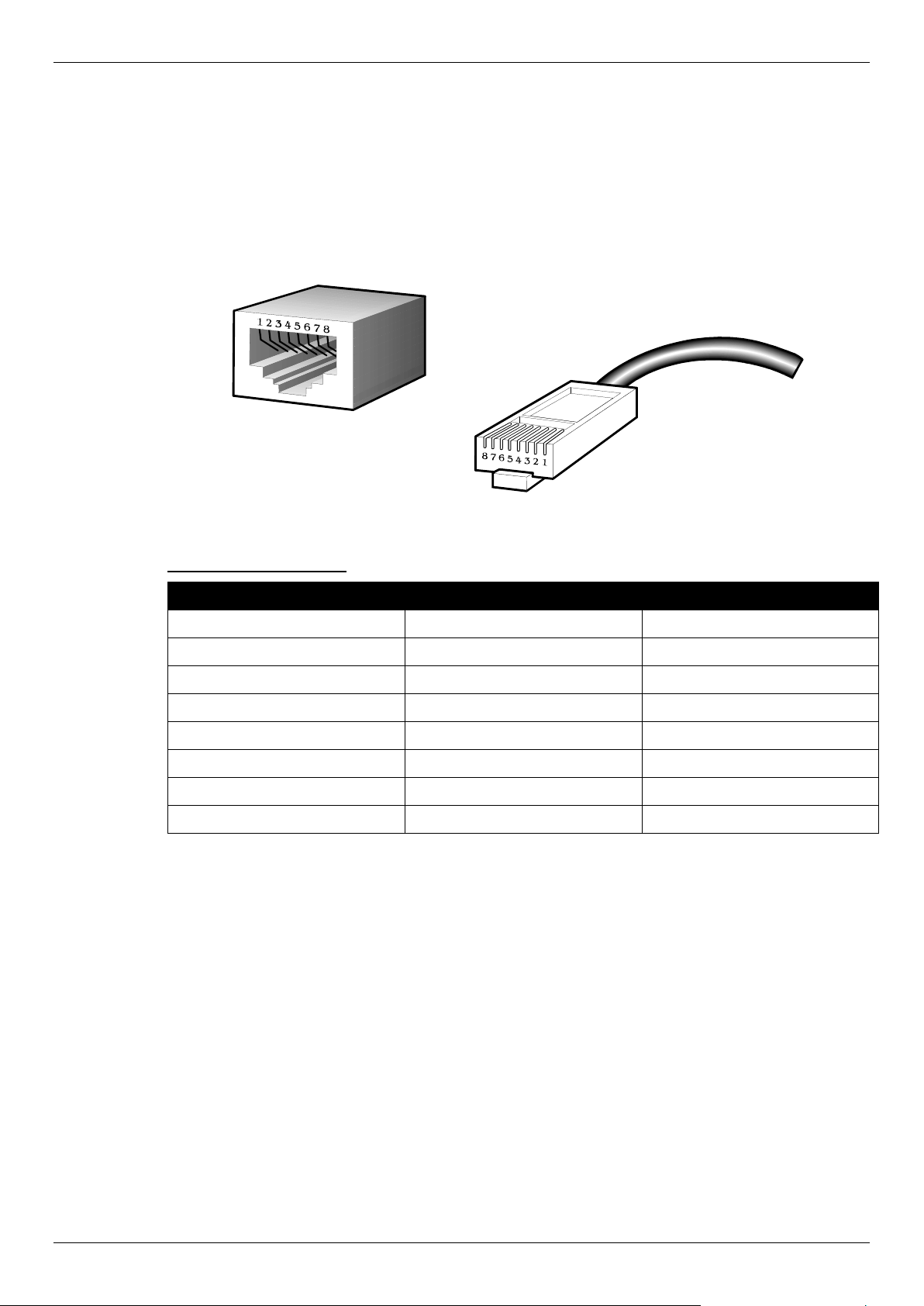
DGS-1510 Series Gigabit Ethernet SmartPro Switch Hardware Installation Guide
45
Appendix B – Cables and Connectors
Ethernet Cable
When connecting the Switch to another switch, a bridge or hub, a normal cable is necessary. Please
review these products for matching cable pin assignment. The following diagrams and tables show
the standard RJ-45 connector and their pin assignments.
Figure B–1 Standard RJ-45 port and connector
RJ-45 PIN Assignments:
Pin MDI-X Port MDI-II Port
1 RD+ (receive) TD+ (transmit)
2 RD- (receive) TD- (transmit)
3 TD+ (transmit) RD+ (receive)
4 1000BASE-T 1000BASE-T
5 1000BASE-T 1000BASE-T
6 TD- (transmit) RD- (receive)
7 1000BASE-T 1000BASE-T
8 1000BASE-T 1000BASE-T
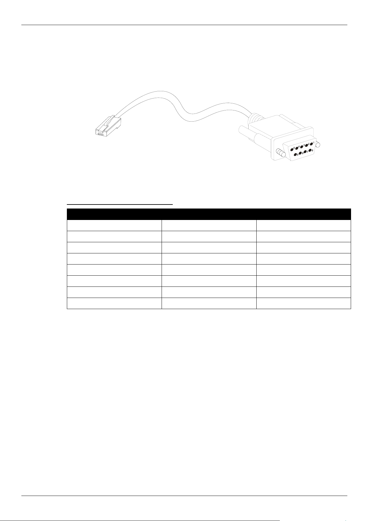
DGS-1510 Series Gigabit Ethernet SmartPro Switch Hardware Installation Guide
46
Console Cable
When connecting the Switch to a PC, a Console cable is necessary. The following diagrams and
tables show the standard Console-to-DJ-45 receptacle/connector and their pin assignments.
Figure B–2 Console-to-RJ-45 Cable
Console-to-RJ-45 PIN Assignments:
Pin Console (DB9/RS232) RJ-45
1 Not Used Not Used
2 RXD Not Used
3 TXD TXD
4 Not Used GND
5 GND (shared) GND
6 Not Used RXD
7 Not Used Not Used
8 Not Used Not Used
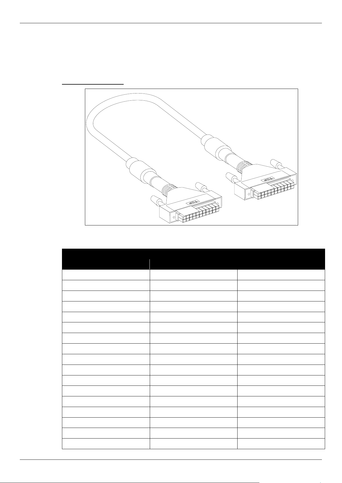
DGS-1510 Series Gigabit Ethernet SmartPro Switch Hardware Installation Guide
47
Redundant Power Supply (RPS) Cable
When connecting the Switch to a Redundant Power Supply, an RPS cable is necessary. Please
review these products for matching cable pin assignment. The following diagrams and tables show
the standard RPS receptacle/connector and their pin assignments.
22-pin DC power cable
Figure B–2 Redundant Power Supply (RPS) 22-pin DC Power Cable
RPS 22-pin DC Power Cable Pin Assignments
Pin Device DPS-700
1 -54Vrtn -54Vrtn
2 -54V -54V
3 +12V +12V
4 +12V +12V
5 +12V +12V
6 +12V +12V
7 NC/GND GND
8 +12Ven +12Ven
9 LS-54V LS-54V
10 -54V -54V
11 -54Vrtn -54Vrtn
12 GND NC/GND
13 GND GND
14 RPS Present Status_2
15 Status_1 RPS PG
16 Status_2 RPS Present
17 RPS PG Status_1

DGS-1510 Series Gigabit Ethernet SmartPro Switch Hardware Installation Guide
48
18 GND GND
19 +12VRTNsen +12VRTNsen
20 LS+12V LS+12V
21 -54Vsen -54Vsen
22 -54VRTNsen -54VRTNsen

DGS-1510 Series Gigabit Ethernet SmartPro Switch Hardware Installation Guide
49
Appendix C – ERPS Information
Only hardware-based ERPS (external PHY) supports the fast link drop interrupt feature with a
recovery time of 50ms.
Model Name ERPS Port 1 to 20
DGS-1510-20 Hardware-based
Software-based V
Model Name ERPS Port 1 to 8 Port 9 to 28
DGS-1510-28
DGS-1510-28P
DGS-1510-28X
DGS-1510-28XMP
Hardware-based V
Software-based V
Model Name ERPS Port 1 to 8 Port 9 to 24 Port 25 to 32 Port 33 to 52
DGS-1510-52 Hardware-based V V
Software-based V V
Model Name ERPS Port 1
to 8
Port 9
to 24
Port 25
to 32
Port 33
to 48
Port 49
and 50
Port 51
and 52
DGS-1510-52X
(HW: A1)
Hardware-based V V V
Software-based V V V
Model Name ERPS Port 1 to
16
Port 17
to 24
Port 25
to 40
Port 41
to 48
Port 49 to
52
DGS-1510-52X
(HW: A2)
DGS-1510-52XMP
Hardware-based V V
Software-based V V V

DGS-1510 Series Gigabit Ethernet SmartPro Switch Hardware Installation Guide
50
Safety/Sécurité
Safety Instructions
Consignes de sécurité
General Precautions for Rack-Mountable Products
Protecting Against Electrostatic Discharge
Safety Instructions
Please pay careful attention to the following safety guidelines to ensure your own personal safety and
to help protect your system from potential damage.
Safety Cautions
To greatly reduce the risk of physical injury, electrical shock, fire, and damage to equipment, observe
the following precautions.
Observe and follow service markings.
• Do not attempt to service any product, except when it is explained in the system’s documentation.
• Opening or removing covers, marked with a high voltage sign, may expose the user to electrical
shock.
• Only a trained service technician should service components inside these compartments.
If any of the following conditions occur, unplug the product from the electrical outlet and replace the
part or contact your trained service provider:
• Damage to the power cable, extension cable, or plug.
• An object has fallen into the product.
• The product has been exposed to water.
• The product has been dropped or damaged.
• The product does not operate correctly when the operating instructions are correctly followed.
General safety cautions:
• Electrical Hazard: Only qualified personnel should perform installation procedures.
• Before servicing, disconnect all power cords to remove power from the device.
• Keep the system away from radiators and heat sources. Also, do not block cooling vents.
• Do not spill food or liquids on system components, and never operate the product in a wet
environment. If the system gets wet, contact your trained service provider.
• Do not push any objects into the openings of the system. Doing so can cause fire or electric
shock by shorting out interior components.
• Only use this product with approved equipment.
• Allow the product to cool before removing the cover or touching internal components.
• Operate the product only from the type of external power source indicated on the electrical ratings
label. If unsure of the type of power source required, consult your service provider or local power
company.
• Be sure that attached devices are electrically rated to operate with the power available in your
location.
• Use only approved power cable(s). If you have not been provided with a power cable for your
system or for any AC-powered option intended for your system, purchase a power cable that is
approved for use in your country. The power cable must be rated for the product and for the

DGS-1510 Series Gigabit Ethernet SmartPro Switch Hardware Installation Guide
51
voltage and current marked on the product's electrical ratings label. The voltage and current rating
of the cable should be greater than the ratings marked on the product.
• To help prevent electric shock, plug the system and peripheral power cables into properly
grounded electrical outlets. These cables are equipped with three-prong plugs to help ensure
proper grounding. Do not use adapter plugs or remove the grounding prong from a cable. If using
an extension cable is necessary, use a 3-wire cable with properly grounded plugs.
• Observe the extension cable and power strip ratings. Make sure that the total ampere rating of all
products plugged into the extension cable or power strip does not exceed 80 percent of the
ampere ratings limit for the extension cable or power strip.
• To help protect the system from sudden, transient increases and decreases in electrical power,
use a surge suppressor, line conditioner, or uninterruptible power supply (UPS).
• Position system cables and power cables carefully. Route cables so that they cannot be stepped
on or tripped over. Be sure that nothing rests on any cables.
• Do not modify power cables or plugs. Consult a licensed electrician or your power company for
site modifications. Always follow your local or national wiring rules.
When connecting or disconnecting power to and from hot-pluggable power supplies, observe the
following guidelines:
• Install the power supply before connecting the power cable to the power supply.
• Unplug the power cable before removing the power supply.
• If the system has multiple sources of power, disconnect power from the system by unplugging all
power cables from the power supplies.
• Move products with care and ensure that all casters and stabilizers are firmly connected to the
system. Avoid sudden stops and uneven surfaces.
To help avoid damage to the system, be sure that the voltage selection switch, on the power supply,
is set to match the power available at the Switch’s location:
• 115V/60Hz is used mostly in North and South America as well as Far Eastern countries like as
South Korea and Taiwan
• 100V/50Hz is used mostly in Eastern Japan and 100V/60Hz in Western Japan
• 230V/50Hz is used mostly in Europe, the Middle East, Africa and the Far East
Consignes de sécurité
Veuillez prêter une attention particulière aux consignes de sécurité suivantes pour assurer votre
sécurité personnelle et protéger votre système des dommages potentiels.
Précautions de sécurité
Pour réduire considérablement les risques de blessure physique, de choc électrique, d'incendie et de
détérioration du matériel, observez les précautions suivantes.
Observez et respectez les marquages relatifs à l'entretien et/ou aux réparations.
• N'essayez pas de réparer un produit, sauf si cela est expliqué dans la documentation du système.
• L'ouverture ou le retrait des capots, signalés par un symbole de haute tension, peut exposer
l'utilisateur à un choc électrique.
• Seul un technicien de maintenance qualifié est habilité à réparer les composants à l'intérieur de
ces compartiments.

DGS-1510 Series Gigabit Ethernet SmartPro Switch Hardware Installation Guide
52
Si l'un des cas suivants se produit, débranchez l'appareil du secteur et remplacez la pièce concernée
ou contactez votre prestataire de services agréé.
• Endommagement du câble d'alimentation, du câble de rallonge ou de la fiche.
• Un objet est tombé dans le produit.
• Le produit a été exposé à l'eau.
• Le produit est tombé ou a été endommagé.
• Le produit ne fonctionne pas correctement lorsque les instructions d'utilisation sont correctement
suivies.
Précautions générales de sécurité:
• Danger électrique: Seul le personnel qualifié doit effectuer les procédures d'installation.
• Avant de procéder à l'entretien, débranchez tous les cordons d'alimentation pour mettre le
périphérique hors tension.
• Eloignez le système des radiateurs et des sources de chaleur. Par ailleurs, n'obturez pas les
fentes d'aération.
• Ne versez pas de liquide sur les composants du système et n'introduisez pas de nourriture à
l'intérieur. Ne faites jamais fonctionner l'appareil dans un environnement humide. Si le système
est mouillé, contactez votre prestataire de services qualifié.
• N'insérez aucun objet dans les fentes de l'appareil. Vous risqueriez de provoquer un incendie ou
un choc électrique en court-circuitant les composants internes.
• Utilisez ce produit uniquement avec un équipement approuvé.
• Laissez l'appareil refroidir avant de déposer le capot ou de toucher les composants internes.
• Faites fonctionner le produit uniquement avec la source d'alimentation indiquée sur l'étiquette
signalétique où figurent les caractéristiques électriques nominales. Si vous ne savez pas avec
certitude quel type de source d'alimentation est requis, consultez votre prestataire de services ou
votre compagnie d'électricité.
• Assurez-vous que les caractéristiques nominales des appareils branchés correspondant à la
tension du réseau électrique.
• Utilisez uniquement des câbles d'alimentation homologués. Si un câble d'alimentation n'est pas
fourni pour le système ou pour un composant/accessoire alimenté par CA destiné au système,
procurez-vous un câble d'alimentation homologué pour une utilisation dans votre pays. Le câble
d'alimentation doit être adapté à l'appareil et ses caractéristiques nominales doivent correspondre
à celles figurant sur l'étiquette du produit. La tension et le courant nominaux du câble doivent être
supérieurs aux valeurs nominales indiquées sur l'appareil.
• Pour éviter tout risque de choc électrique, branchez les câbles d'alimentation du système et des
périphériques à des prises électriques correctement mises à la masse. Ces câbles sont équipés
de fiches à trois broches pour garantir une mise à la masse appropriée. N'utilisez pas
d'adaptateur de prise, et n'éliminez pas la broche de mise à la masse du câble. Si un câble de
rallonge est nécessaire, utilisez un câble à 3 fils avec des fiches correctement mises à la terre.
• Respectez les caractéristiques nominales de la rallonge ou du bloc multiprise. Assurez-vous que
l'intensité nominale totale de tous les produits branchés à la rallonge ou au bloc multiprise ne
dépasse pas 80 % de l'intensité nominale limite de la rallonge ou du bloc multiprise.
• Pour protéger le système contre les pics et les chutes de tension transitoires et soudains, utilisez
un parasurtenseur, un filtre de secteur ou une alimentation sans interruption (ASI).
• Positionnez les câbles système et les câbles d'alimentation avec soin. Acheminez les câbles de
manière à ce qu'ils ne puissent pas être piétinés ou trébuchés. Veillez à ce que rien ne repose sur
les câbles.
• Ne modifiez pas les câbles ou les fiches d'alimentation. Contactez un électricien qualifié ou la
compagnie d'électricité si des modifications sur site sont nécessaires. Respectez toujours la
règlementation locale ou nationale en matière de câblage.
Lors de la connexion ou de la déconnexion de l'alimentation vers et depuis des blocs d'alimentation
enfichables à chaud, respectez les consignes suivantes:
• Installez l'alimentation avant d'y brancher le câble d'alimentation.
• Débranchez le câble d'alimentation avant de couper l'alimentation.

DGS-1510 Series Gigabit Ethernet SmartPro Switch Hardware Installation Guide
53
• Si le système possède plusieurs sources d'alimentation, mettez-le hors tension en débranchant
tous les câbles d'alimentation des prises.
• Déplacez les appareils avec précaution et assurez-vous que les roulettes et/ou que les pieds
stabilisateurs sont bien fixés au système. Évitez les arrêts brusques et les surfaces inégales.
Pour éviter d'endommager le système, assurez-vous que le commutateur de sélection de tension de
l'alimentation est réglé sur l'alimentation disponible à l'emplacement du commutateur:
• 115 V/60 Hz est principalement utilisé en Amérique du Nord et du Sud, ainsi que dans des pays
d'Extrême-Orient tels que la Corée du Sud et Taïwan.
• 100 V/50 Hz est utilisé principalement dans l'est du Japon et 100 V/ 60 Hz dans l'ouest du Japon.
• 230 V/50 Hz est principalement utilisé en Europe, au Moyen-Orient, en Afrique et en Extrême-
Orient.
General Precautions for Rack-Mountable Products
Please pay careful attention to the following precautions concerning rack stability and safety. Systems
are considered to be components in a rack. Thus, a component refers to any system, as well as to
various peripherals or supporting hardware:
CAUTION: Installing systems in a rack without the front and side stabilizers installed
could cause the rack to tip over, potentially resulting in bodily injury under certain
circumstances. Therefore, always install the stabilizers before installing
components in the rack. After installing system/components in a rack, never pull
more than one component out of the rack on its slide assemblies at one time.
The weight of more than one extended component could cause the rack to tip
over and may result in serious injury.
ATTENTION : Le montage de systèmes sur un rack dépourvu de pieds stabilisateurs
avant et latéraux peut faire basculer le rack, pouvant causer des dommages
corporels dans certains cas. Par conséquent, installez toujours les pieds
stabilisateurs avant de monter des composants sur le rack. Après l'installation
d'un système ou de composants dans un rack, ne sortez jamais plus d'un
composant à la fois hors du rack sur ses glissières. Le poids de plusieurs
composants sur les glissières en extension peut faire basculer le rack, pouvant
causer de graves dommages corporels.
• Before working on the rack, make sure that the stabilizers are secured to the rack, extended to
the floor, and that the full weight of the rack rests on the floor. Install front and side stabilizers on a
single rack or front stabilizers for joined multiple racks before working on the rack.
• Always load the rack from the bottom up, and load the heaviest item in the rack first.
• Make sure that the rack is level and stable before extending a component from the rack.
• Use caution when pressing the component rail release latches and sliding a component into or
out of a rack; the slide rails can pinch your fingers.
• After a component is inserted into the rack, carefully extend the rail into a locking position, and
then slide the component into the rack.
• Do not overload the AC supply branch circuit that provides power to the rack. The total rack load
should not exceed 80 percent of the branch circuit rating.
• Ensure that proper airflow is provided to components in the rack.
• Do not step on or stand on any component when servicing other components in a rack.

DGS-1510 Series Gigabit Ethernet SmartPro Switch Hardware Installation Guide
54
CAUT
ION: Never defeat the ground conductor or operate the equipment in the absence
of a suitably installed ground conductor. Contact the appropriate electrical
inspection authority or an electrician if uncertain that suitable grounding is
available.
A
TTENTION : Ne neutralisez jamais le conducteur de masse et ne faites jamais
fonctionner le matériel en l'absence de conducteur de masse dûment installé.
Contactez l'organisme de contrôle en électricité approprié ou un électricien
qualifié si vous n'êtes pas sûr qu'un système de mise à la masse adéquat soit
disponible.
CAUT
ION: The system chassis must be positively grounded to the rack cabinet frame.
Do not attempt to connect power to the system until grounding cables are
connected. Completed power and safety ground wiring must be inspected by a
qualified electrical inspector. An energy hazard will exist if the safety ground
cable is omitted or disconnected.
ATTENTION : La carcasse du système doit être positivement reliée à la masse du cadre
du rack. N'essayez pas de mettre le système sous tension si les câbles de mise
à la masse ne sont pas raccordés. Le câblage de l'alimentation et de la mise à la
masse de sécurité doit être inspecté par un inspecteur qualifié en électricité. Un
risque électrique existe si le câble de mise à la masse de sécurité est omis ou
débranché.
Protecting Against Electrostatic Discharge
Static electricity can harm delicate components inside the system. To prevent static damage,
discharge static electricity from your body before touching any of the electronic components, such as
the microprocessor. This can be done by periodically touching an unpainted metal surface on the
chassis.
T
he following steps can also be taken prevent damage from electrostatic discharge (ESD):
• When unpacking a static-sensitive component from its shipping carton, do not remove th
e
c
omponent from the antistatic packing material until ready to install the component in the system.
Just before unwrapping the antistatic packaging, be sure to discharge static electricity from your
body.
• When transporting a sensitive component, first place it in an antistatic container or packaging.
• Handle all sensitive components in a static-safe area. If possible, use antistatic floor pads,
workbench pads and an antistatic grounding strap.

Subject to the terms and conditions set forth herein, D-Link Systems, Inc. (“D-Link”) provides this Limited Warranty:
• Only to the person or entity that originally purchased the product from D-Link or its authorized reseller or distributor, and
• Only for products purchased and delivered within the fifty states of the United States, the District of Columbia, U.S. Possessions or Protectorates,
U.S. Military Installations, or addresses with an APO or FPO.
Limited Warranty: D-Link warrants that the hardware portion of the D-Link product described below (“Hardware”) will be free from material defects in
workmanship and materials under normal use from the date of original retail purchase of the product, for the period set forth below (“Warranty Period”),
except as otherwise stated herein.
Limited Lifetime Warranty for the product is defined as follows:
• Hardware: For as long as the original customer/end user owns the product, or five (5) years after product discontinuance, whichever occurs first
(excluding power supplies and fans)
• Power supplies and fans: Three (3) Year
• Spare parts and spare kits: Ninety (90) days
The customer's sole and exclusive remedy and the entire liability of D-Link and its suppliers under this Limited Warranty will be, at D-Link’s option, to
repair or replace the defective Hardware during the Warranty Period at no charge to the original owner or to refund the actual purchase price paid. Any
repair or replacement will be rendered by D-Link at an Authorized D-Link Service Office. The replacement hardware need not be new or have an identical
make, model or part. D-Link may, at its option, replace the defective Hardware or any part thereof with any reconditioned product that D-Link reasonably
determines is substantially equivalent (or superior) in all material respects to the defective Hardware. Repaired or replacement hardware will be
warranted for the remainder of the original Warranty Period or ninety (90) days, whichever is longer, and is subject to the same limitations and exclusions.
If a material defect is incapable of correction, or if D-Link determines that it is not practical to repair or replace the defective Hardware, the actual price
paid by the original purchaser for the defective Hardware will be refunded by D-Link upon return to D-Link of the defective Hardware. All Hardware or part
thereof that is replaced by D-Link, or for which the purchase price is refunded, shall become the property of D-Link upon replacement or refund.
Limited Software Warranty: D-Link warrants that the software portion of the product (“Software”) will substantially conform to D-Link’s then current
functional specifications for the Software, as set forth in the applicable documentation, from the date of original retail purchase of the Software for a period
of ninety (90) days (“Software Warranty Period”), provided that the Software is properly installed on approved hardware and operated as contemplated in
its documentation. D-Link further warrants that, during the Software Warranty Period, the magnetic media on which D-Link delivers the Software will be
free of physical defects. The customer's sole and exclusive remedy and the entire liability of D-Link and its suppliers under this Limited Warranty will be,
at D-Link’s option, to replace the non-conforming Software (or defective media) with software that substantially conforms to D-Link’s functional
specifications for the Software or to refund the portion of the actual purchase price paid that is attributable to the Software. Except as otherwise agreed
by D-Link in writing, the replacement Software is provided only to the original licensee, and is subject to the terms and conditions of the license granted by
D-Link for the Software. Replacement Software will be warranted for the remainder of the original Warranty Period and is subject to the same limitations
and exclusions. If a material non-conformance is incapable of correction, or if D-Link determines in its sole discretion that it is not practical to replace the
non-conforming Software, the price paid by the original licensee for the non-conforming Software will be refunded by D-Link; provided that the non-
conforming Software (and all copies thereof) is first returned to D-Link. The license granted respecting any Software for which a refund is given
automatically terminates.
Non-Applicability of Warranty: The Limited Warranty provided hereunder for Hardware and Software portions of D-Link's products will not be applied to
and does not cover any refurbished product and any product purchased through the inventory clearance or liquidation sale or other sales in which D-Link,
the sellers, or the liquidators expressly disclaim their warranty obligation pertaining to the product and in that case, the product is being sold "As-Is"
without any warranty whatsoever including, without limitation, the Limited Warranty as described herein, notwithstanding anything stated herein to the
contrary.
Submitting A Claim: The customer shall return the product to the original purchase point based on its return policy. In case the return policy period has
expired and the product is within warranty, the customer shall submit a claim to D-Link as outlined below:
• The customer must submit with the product as part of the claim a written description of the Hardware defect or Software nonconformance in sufficient
detail to allow D-Link to confirm the same, along with proof of purchase of the product (such as a copy of the dated purchase invoice for the product)
if the product is not registered.
• The customer must obtain a Case ID Number from D-Link Technical Support at 1-877-453-5465, who will attempt to assist the customer in resolving
any suspected defects with the product. If the product is considered defective, the customer must obtain a Return Material Authorization (“RMA”)
number by completing the RMA form and entering the assigned Case ID Number at https://rma.dlink.com/
.
• After an RMA number is issued, the defective product must be packaged securely in the original or other suitable shipping package to ensure that it
will not be damaged in transit, and the RMA number must be prominently marked on the outside of the package. Do not include any manuals or
accessories in the shipping package. D-Link will only replace the defective portion of the product and will not ship back any accessories.
• The customer is responsible for all in-bound shipping charges to D-Link. No Cash on Delivery (“COD”) is allowed. Products sent COD will either be
rejected by D-Link or become the property of D-Link. Products shall be fully insured by the customer and shipped to D-Link Systems, Inc., 17595
Mt. Herrmann, Fountain Valley, CA 92708. D-Link will not be held responsible for any packages that are lost in transit to D-Link. The repaired or
replaced packages will be shipped to the customer via UPS Ground or any common carrier selected by D-Link. Return shipping charges shall be
prepaid by D-Link if you use an address in the United States, otherwise we will ship the product to you freight collect. Expedited shipping is available
upon request and provided shipping charges are prepaid by the customer.
D-Link may reject or return any product that is not packaged and shipped in strict compliance with the foregoing requirements, or for which an RMA
number is not visible from the outside of the package. The product owner agrees to pay D-Link’s reasonable handling and return shipping charges for any
product that is not packaged and shipped in accordance with the foregoing requirements, or that is determined by D-Link not to be defective or non-
conforming.
What Is Not Covered: The Limited Warranty provided herein by D-Link does not cover: Products that, in D-Link’s judgment, have been subjected to
abuse, accident, alteration, modification, tampering, negligence, misuse, faulty installation, lack of reasonable care, repair or service in any way that is not
contemplated in the documentation for the product, or if the model or serial number has been altered, tampered with, defaced or removed; Initial
installation, installation and removal of the product for repair, and shipping costs; Operational adjustments covered in the operating manual for the product,
and normal maintenance; Damage that occurs in shipment, due to act of God, failures due to power surge, and cosmetic damage; Any hardware,
software, firmware or other products or services provided by anyone other than D-Link; and Products that have been purchased from inventory clearance
or liquidation sales or other sales in which D-Link, the sellers, or the liquidators expressly disclaim their warranty obligation pertaining to the product.
While necessary maintenance or repairs on your Product can be performed by any company, we recommend that you use only an Authorized D-Link
Service Office. Improper or incorrectly performed maintenance or repair voids this Limited Warranty.
Disclaimer of Other Warranties: EXCEPT FOR THE LIMITED WARRANTY SPECIFIED HEREIN, THE PRODUCT IS PROVIDED “AS-IS” WITHOUT
ANY WARRANTY OF ANY KIND WHATSOEVER INCLUDING, WITHOUT LIMITATION, ANY WARRANTY OF MERCHANTABILITY, FITNESS FOR A
PARTICULAR PURPOSE AND NON-INFRINGEMENT. IF ANY IMPLIED WARRANTY CANNOT BE DISCLAIMED IN ANY TERRITORY WHERE A
PRODUCT IS SOLD, THE DURATION OF SUCH IMPLIED WARRANTY SHALL BE LIMITED TO NINETY (90) DAYS. EXCEPT AS EXPRESSLY
COVERED UNDER THE LIMITED WARRANTY PROVIDED HEREIN, THE ENTIRE RISK AS TO THE QUALITY, SELECTION AND PERFORMANCE
OF THE PRODUCT IS WITH THE PURCHASER OF THE PRODUCT.

Limitation of Liability: TO THE MAXIMUM EXTENT PERMITTED BY LAW, D-LINK IS NOT LIABLE UNDER ANY CONTRACT, NEGLIGENCE,
STRICT LIABILITY OR OTHER LEGAL OR EQUITABLE THEORY FOR ANY LOSS OF USE OF THE PRODUCT, INCONVENIENCE OR DAMAGES OF
ANY CHARACTER, WHETHER DIRECT, SPECIAL, INCIDENTAL OR CONSEQUENTIAL (INCLUDING, BUT NOT LIMITED TO, DAMAGES FOR LOSS
OF GOODWILL, LOSS OF REVENUE OR PROFIT, WORK STOPPAGE, COMPUTER FAILURE OR MALFUNCTION, FAILURE OF OTHER
EQUIPMENT OR COMPUTER PROGRAMS TO WHICH D-LINK’S PRODUCT IS CONNECTED WITH, LOSS OF INFORMATION OR DATA
CONTAINED IN, STORED ON, OR INTEGRATED WITH ANY PRODUCT RETURNED TO D-LINK FOR WARRANTY SERVICE) RESULTING FROM
THE USE OF THE PRODUCT, RELATING TO WARRANTY SERVICE, OR ARISING OUT OF ANY BREACH OF THIS LIMITED WARRANTY, EVEN IF
D-LINK HAS BEEN ADVISED OF THE POSSIBILITY OF SUCH DAMAGES. THE SOLE REMEDY FOR A BREACH OF THE FOREGOING LIMITED
WARRANTY IS REPAIR, REPLACEMENT OR REFUND OF THE DEFECTIVE OR NON-CONFORMING PRODUCT. THE MAXIMUM LIABILITY OF D-
LINK UNDER THIS WARRANTY IS LIMITED TO THE PURCHASE PRICE OF THE PRODUCT COVERED BY THE WARRANTY. THE FOREGOING
EXPRESS WRITTEN WARRANTIES AND REMEDIES ARE EXCLUSIVE AND ARE IN LIEU OF ANY OTHER WARRANTIES OR REMEDIES,
EXPRESS, IMPLIED OR STATUTORY.
Governing Law: This Limited Warranty shall be governed by the laws of the State of California. Some states do not allow exclusion or limitation of
incidental or consequential damages, or limitations on how long an implied warranty lasts, so the foregoing limitations and exclusions may not apply. This
Limited Warranty provides specific legal rights and you may also have other rights which vary from state to state.
Trademarks: D-Link is a registered trademark of D-Link Systems, Inc. Other trademarks or registered trademarks are the property of their respective
owners.
Copyright Statement: No part of this publication or documentation accompanying this product may be reproduced in any form or by any means or used
to make any derivative such as translation, transformation, or adaptation without permission from D-Link Corporation/D-Link Systems, Inc., as stipulated
by the United States Copyright Act of 1976 and any amendments thereto. Contents are subject to change without prior notice. Copyright 2004 by D-Link
Corporation/D-Link Systems, Inc. All rights reserved.
CE Mark Warning: This is a Class A product. In a residential environment, this product may cause radio interference, in which case the user may be
required to take adequate measures.
FCC Statement: This equipment has been tested and found to comply with the limits for a Class A digital device, pursuant to part 15 of the FCC Rules.
These limits are designed to provide reasonable protection against harmful interference in a commercial installation. This equipment generates, uses, and
can radiate radio frequency energy and, if not installed and used in accordance with the instructions, may cause harmful interference to radio
communication. However, there is no guarantee that interference will not occur in a particular installation. Operation of this equipment in a residential
environment is likely to cause harmful interference to radio or television reception. If this equipment does cause harmful interference to radio or television
reception, which can be determined by turning the equipment off and on, the user is encouraged to try to correct the interference by one or more of the
following measures:
• Reorient or relocate the receiving antenna.
• Increase the separation between the equipment and receiver.
• Connect the equipment into an outlet on a circuit different from that to which the receiver is connected.
• Consult the dealer or an experienced radio/TV technician for help.
For detailed warranty information applicable to products purchased outside the United States, please contact the corresponding
local D-Link office.


Technical Support
U.S. and Canadian customers
This guide is only for initial configuration. Please refer to the user manual
to learn more or visit http://www.mydlink.com for more information.
Also feel free to contact us. U.S. and Canadian customers can contact
D-Link Technical Support through our website.
USA
http://support.dlink.com
Canada
http://support.dlink.ca

Europe customers
TECHNICAL SUPPORT
eu.dlink . com/suppor t
TECHNISCHE
UNTERSTÜTZUNG
ASSISTANCE TECHNIQUE
ASISTENCIA TÉCNICA
SUPPORTO TECNICO
TECHNISCHE
ONDERSTEUNING
POMOC TECHNICZNA
TECHNICKÁ PODPORA
TECHNIKAI TÁMOGATÁS
TEKNISK STØTTE
TEKNISK SUPPORT
TEKNINEN TUKI
TEKNISK SUPPORT
ASSISTÊNCIA TÉCNICA
ΤΕΧΝΙΚΉ ΥΠΟΣΤΉΡΙΞΗ
TEHNIČKA PODRŠKA
TEHNIČNA PODPORA
SUPORT TEHNIC
ТЕХНИЧЕСКА ПОДДРЪЖКА
TECHNICKÁ PODPORA

Australia customers
Tel: 1300-700-100
24/7 Technical Support
Web: http://www.dlink.com.au
E-mail: support@dlink.com.au
India customers
Tel: +91-832-2856000 or 1860-233-3999
Web: in.dlink.com
E-Mail: helpdesk@in.dlink.com
Singapore, Thailand, Indonesia, Malaysia, Philippines,
Vietnam customers
Singapore - www.dlink.com.sg
Thailand - www.dlink.co.th
Indonesia - www.dlink.co.id
Malaysia - www.dlink.com.my
Philippines - www.dlink.com.ph
Vietnam - www.dlink.com.vn
Korea customers
Tel : 1899-3540
Monday to Friday 9:30am to 6:30pm
Web : http://d-link.co.kr
E-mail : support@kr.dlink.com
New Zealand customers
Tel: 0800-900-900
24/7 Technical Support
Web: http://www.dlink.co.nz
E-mail: support@dlink.co.nz
South Africa and Sub Sahara Region customers
Tel: +27 12 661 2025
08600 DLINK (for South Africa only)
Monday to Friday 8:30am to 9:00pm South Africa Time
Web: http://www.d-link.co.za
E-mail: support@za.dlink.com

D-Link Middle East - Dubai, U.A.E.
Plot No. S31102, Jebel Ali Free Zone South, P.O.Box 18224, Dubai, U.A.E.
Tel: +971-4-8809022
Fax: +971-4-8809066 / 8809069
Technical Support: +971-4-8809033
General Inquiries: [email protected]
Tech Support: support.me@me.dlink.com
Egypt
19 Helmy El-Masry, Almaza, Heliopolis Cairo, Egypt
Tel: +202-24147906
Technical Support Center no. : +202-25866777
General Inquiries: info.eg@me.dlink.com
Kingdom of Saudi Arabia
Riyadh - Saudi Arabia
E-Mail info.sa@me.dlink.com
Pakistan
Karachi Office:
D-147/1, KDA Scheme #1, Opposite Mudassir Park, Karsaz Road, Karachi – Pakistan
Phone: +92-21- 34548158, 34305069
Fax: +92-21-4375727
General Inquiries: [email protected]
Morocco
Sidi Maarouf Bussiness Centre, 1100 Bd El Qods, Casanearshore 1
Casablanca 20270
Phone office: +212 700 13 14 15
Email: morocco@me.dlink.com
Bahrain
Technical Support: +973 1 3332904
Kuwait:
Tech Support: kuwait@me.dlink.com

Техническая Поддержка
Обновления программного обеспечения и документация доступны на
Интернет-сайте D-Link.
D-Link предоставляет бесплатную поддержку для клиентов в течение
гарантийного срока.
Клиенты могут обратиться в группу технической поддержки D-Link по
телефону или через Интернет.
Техническая поддержка компании D-Link работает в круглосуточном
режиме ежедневно, кроме официальных праздничных дней. Звонок
бесплатный по всей России.
Техническая поддержка D-Link:
8-800-700-5465
Техническая поддержка через Интернет:
http://www.dlink.ru
e-mail: support@dlink.ru
Изготовитель:
Д-Линк
Корпорейшн,
114,
Тайвань,
Тайпей,
Нэйху
Дистрикт,
Шинху
3-Роуд,
№ 289
Уполномоченный представитель, импортер:
ООО “Д-Линк Трейд”
390043, г.Рязань, пр. Шабулина, д.16
Тел.: +7 (4912) 503-505

Офисы
Россия
Москва, Графский переулок, 14
Тел. : +7 (495) 744-00-99
E-mail: mail@dlink.ru
Україна
Київ, вул. Межигірська, 87-А
Тел.: +38 (044) 545-64-40
E-mail: ua@dlink.ua
Moldova
Chisinau; str.C.Negruzzi-8
Tel: +373 (22) 80-81-07
E-mail:[email protected]
Беларусь
Мінск, пр-т Незалежнасці, 169
Тэл.: +375 (17) 218-13-65
E-mail: support@dlink.by
Қазақстан
Алматы, Құрманғазы к-cі,143 үй
Тел.: +7 (727) 378-55-90
E-mail: almaty@dlink.ru
Հայաստան
Երևան, Դավթաշեն 3-րդ
թաղամաս, 23/5
Հեռ.՝ +374 (10) 39-86-67
Էլ. փոստ՝ info@dlink.am
Lietuva
Vilnius, Žirmūnų 139-303
Tel.: +370 (5) 236-36-29
E-mail: info@dlink.lt
Eesti
E-mail: info@dlink.ee
Türkiye
Uphill Towers Residence A/99
Ataşehir /ISTANBUL
Tel: +90 (216) 492-99-99
Email: info.tr@dlink.com.tr
לארשי
םימישגמה 'חר
20
ןולטמ תירק
הווקת חתפ
072-2575555

Soporte Técnico Para Usuarios En Latino America
Por favor revise el número telefónico del Call Center de su país en
http://www.dlinkla.com/soporte/call-center
Soporte Técnico de D-Link a través de Internet
Horario de atención Soporte Técnico en www.dlinkla.com
e-mail: soporte@dlinkla.com & consultas@dlinkla.com
Clientes de Brasil
Caso tenha dúvidas na instalação do produto, entre em contato com o
Suporte Técnico D-Link.
Acesse o site:
www.dlink.com.br/suporte

D-Link
友訊科技 台灣分公司 技術支援資訊
如果您還有任何本使用手冊無法協助您解決的產品相關問題,台灣、香港或是澳門用戶
可至網站、電子郵件或電話等方式與D-Link技術支援工程師聯絡。
台灣
D-Link
免付費技術諮詢專線
台灣技術諮詢服務專線
0800-002-615
台灣手機付費電話
(02) 6600-0123#8715
台灣網站:
http://www.dlink.com.tw
台灣電子郵件:
產品保固期限、台灣技術諮詢時間、維修據點查詢,請參考
http://www.dlink.com.tw
網頁
說明
香港、澳門
D-Link
技術諮詢專線
香港技術諮詢服務專線
(852) 8100 8892
香港網站:
http://www.dlink.com.hk
香港電子郵件:
[email protected]-grp.com
香港、澳門維修據點查詢請參考
http://www.dlink.com.hk/contact.html
網頁說明。
如果您是其他地區的用戶,請參考
D-Link
網站
www.dlink.com
查詢全球各地分公司的聯絡
資訊以取得相關支援服務。

Pelanggan Indonesia
Update perangkat lunak dan dokumentasi pengguna dapat diperoleh
pada situs web D-Link.
Dukungan Teknis untuk pelanggan:
Tel: 0800-14014-97 (Layanan Bebas Pulsa)
Dukungan Teknis D-Link melalui Internet:
Pertanyaan Umum: sales@id.dlink.com
Bantuan Teknis: support@id.dlink.com
Website : http://www.dlink.co.id
日本のお客様
この度は弊社製品をお買い上げいただき、誠にありがとうございます。
製品に同梱されている保証書の購入元にお問い合わせください。
中國客戶
服務熱線:
4006-828-828
週一至周日:
9:00-18:00
技術支持中心郵箱:
dlink400@cn.dlink.com
各地維修中心地址請登錄官方網站查詢
網址:
http://www.dlink.com.cn

Registration Card
All Countries and Regions Excluding USA
Print, type or use block letters.
Your name: Mr./Ms_____________________________________________________________________________
Organization: ________________________________________________ Dept. ____________________________
Your title at organization: ________________________________________________________________________
Telephone: _______________________________________ Fax:________________________________________
Organization's full address: ______________________________________________________________________
____________________________________________________________________________________________
Country: _____________________________________________________________________________________
Date of purchase (Month/Day/Year): _______________________________________________________________
Product Model Product Serial No. * Product installed in type of
computer
* Product installed in
computer serial No.
(* Applies to adapters only)
Product was purchased from:
Reseller's name: ______________________________________________________________________________
Telephone: _______________________________________
Answers to the following questions help us to support your product:
1. Where and how will the product primarily be used?
Home Office Travel Company Business Home Business Personal Use
2. How many employees work at installation site?
1 employee 2-9 10-49 50-99 100-499 500-999 1000 or more
3. What network protocol(s) does your organization use ?
XNS/IPX TCP/IP DECnet Others_____________________________
4. What network operating system(s) does your organization use ?
D-Link LANsmart Novell NetWare NetWare Lite SCO Unix/Xenix PC NFS 3Com 3+Open Cisco Network
Banyan Vines DECnet Pathwork Windows NT Windows 98 Windows 2000/ME Windows XP
Others__________________________________________
5. What network management program does your organization use ?
D-View HP OpenView/Windows HP OpenView/Unix SunNet Manager Novell NMS
NetView 6000 Others________________________________________
6. What network medium/media does your organization use ?
Fiber-optics Thick coax Ethernet Thin coax Ethernet 10BASE-T UTP/STP
100BASE-TX 1000BASE-T
Wireless 802.11b and 802.11g wireless 802.11a Others_________________
7. What applications are used on your network?
Desktop publishing Spreadsheet Word processing CAD/CAM
Database management Accounting Others_____________________
8. What category best describes your company?
Aerospace Engineering Education Finance Hospital Legal Insurance/Real Estate Manufacturing
Retail/Chain store/Wholesale Government Transportation/Utilities/Communication VAR
System house/company Other________________________________
9. Would you recommend your D-Link product to a friend?
Yes No Don't know yet
10.Your comments on this product?
__________________________________________________________________________________________
__________________________________________________________________________________________