Loading ...
Loading ...
Loading ...
6
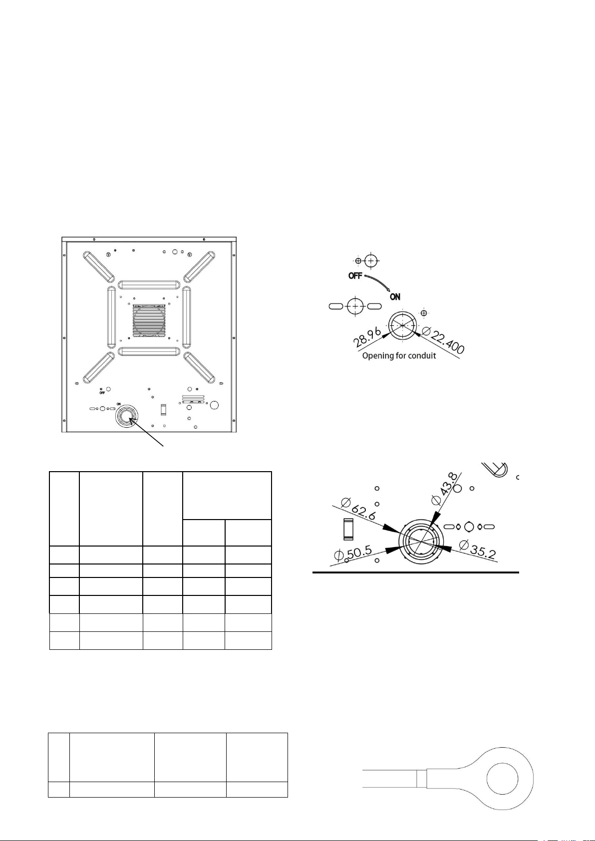
WIRING
BRANCH CIRCUIT (POWER)
1. Connect heater only to the voltage, amperage and frequency specified on the nameplate.
2 Field wiring must be properly sized to carry the amperage in accordance with the NEC.
3 The access door is hinged. There are either one or two screws accessible from the bottom that
must be removed to gain access.
4 A knockout is provided in the back of the heater close to the power terminal board. The control
terminal board knockout is 1/2 inch conduit size. The power terminal block knockout is multiple
diameter. Use the diameter that fits the required conduit size.
5 A ground terminal is provided near the power terminal board. The ground wire should be
connected before other connections are made. Use grounding lug to install the grounding wire.
The ground wire AWG# and the lug screw size is as below list:
No.
Model #
Trade
size of
conduit
(inch)
Knockout(mm)
Nominal
Minimum
1
DR-130
1/2
28.96
22.4
2
DR-350
1/2
28.96
22.4
3
DR-P275
1
43.8
35.2
4
DR-P2100
1
43.8
35.2
5
DR-P3150
1
43.8
35.2
6
DR-P3200
1/2
28.96
22.4
No.
Model#
Grounding
wire
AWG#
Grounding
Lug Screw
Size
1
DR-P130
14
M5X1.0
knockout here
For model DR-P130 and DR-P350
For model DR-P2100, DR-P275,
DR-P3150 and DR-P3200
Loading ...
Loading ...
Loading ...