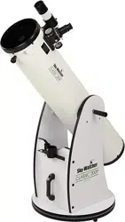
INSTRUCTION MANUAL
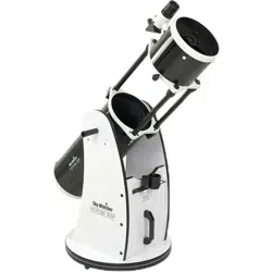
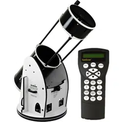
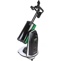
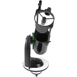
DOBSONIAN SYNSCAN - 8” 10” 12” 14” 16”
180610V6-3.08
ESC
SETUP
ENTER
1
2
3
4
5
6
7
8
9
0
TOUR
UTILITY
RATE
M IC
NGC
PLANET
USER
OBJECT
ID
240412V1

DOBSONIAN BASE ASSEMBLY
TELESCOPE SETUP
ALIGNING THE FINDERSCOPE
FOCUSING
POWER REQUIREMENTS
POWERING THE DOBSONIAN SYNSCAN
THE SYNSCAN AZ
INTRODUCTION TO THE SYNSCAN AZ
SYNSCAN AZ HAND CONTROL
AUTOTRACKING OPERATION
INITIAL SETUP
AUTOMATIC TRACKING
AZ GOTO OPERATION
INITIAL SETUP
STAR ALIGNMENT
POINTING ACCURACY ENHANCEMENT (PAE)
OBJECT DATABASE IN THE SYNSCAN AZ
SELECTING AN OBJECT
UTILITY FUNCTIONS
SETUP FUNCTIONS
USING THE USER DEFINED DATABASE
IDENTIFYING AN UNKNOWN OBJECT
LINKING WITH A COMPUTER
UPDATING THE SYNSCAN AZ FIRMWARE
SYNSCAN AZ MENU TREE
TECHNICAL SPECIFICATIONS
APPENDIX A - RS-232 CONNECTION
APPENDIX B - STANDARD TIME ZONES OF THE WORLD
3
7
8
8
8
8
9
9
9
11
11
11
12
12
12
14
16
16
17
17
18
19
19
20
22
23
I
III
TABLE OF CONTENTS
BEFORE YOU BEGIN
This instruction manual is applicable to all the models listed on the cover. Follow the
instructions for your specific model in the manual. Read the entire instructions
carefully before beginning. Your telescope should be assembled during daylight
hours. Choose a large, open area to work to allow room for all parts to be unpacked.
While every effort has been made to ensure that the information contained in this
instruction manual is accurate and complete, no liability can be accepted for any
errors or omissions. Sky-Watcher Telescope reserves the right to change the
specifications of the hardware and software described herein at any time without
prior notice. Please always check our web site to obtain the latest information:
http://www.skywatchertelescope.net
DOBSONIAN BASE ASSEMBLY – – – – – – – – – – – – – – – – – – – – – – – – – – 3
PRIMARY MIRROR INSTALLATION – – – – – – – – – – – – – – – – – – – – – – – – 7
TELESCOPE SETUP – – – – – – – – – – – – – – – – – – – – – – – – – – – – – – – – 10
ALIGNING THE FINDERSCOPE – – – – – – – – – – – – – – – – – – – – – – 10
FOCUSING – – – – – – – – – – – – – – – – – – – – – – – – – – – – – – – – – 10
POWER REQUIREMENTS – – – – – – – – – – – – – – – – – – – – – – – – – 10
POWERING THE DOBSONIAN SYNSCAN – – – – – – – – – – – – – – – – 10
THE SYNSCAN AZ – – – – – – – – – – – – – – – – – – – – – – – – – – – – – 11
INTRODUCTION TO THE SYNSCAN AZ – – – – – – – – – – – – – – – – – 11
SYNSCAN AZ HAND CONTROL – – – – – – – – – – – – – – – – – – – – – 11
AUTOTRACKING OPERATION – – – – – – – – – – – – – – – – – – – – – – – – – – 13
INITAL SETUP – – – – – – – – – – – – – – – – – – – – – – – – – – – – – – – 13
AUTOMATIC TRACKING – – – – – – – – – – – – – – – – – – – – – – – – – – 13
AZ GOTO OPERATION – – – – – – – – – – – – – – – – – – – – – – – – – – – – – – – 14
INITIAL SETUP – – – – – – – – – – – – – – – – – – – – – – – – – – – – – – – 14
STAR ALIGNMENT – – – – – – – – – – – – – – – – – – – – – – – – – – – – – 14
POINTING ACCURACY ENHANCEMENT (PAE) – – – – – – – – – – – – – 16
OBJECT DATABASE IN THE SYNSCAN AZ – – – – – – – – – – – – – – – – 18
SELECTING AN OBJECT – – – – – – – – – – – – – – – – – – – – – – – – – 18
UTILITY FUNCTIONS – – – – – – – – – – – – – – – – – – – – – – – – – – – 19
SETUP FUNCTIONS – – – – – – – – – – – – – – – – – – – – – – – – – – – – 19
USING THE USER DEFINED DATABASE – – – – – – – – – – – – – – – – – 20
IDENTIFYING AN UNKNOWN OBJECT – – – – – – – – – – – – – – – – – – 21
LINKING WITH A COMPUTER – – – – – – – – – – – – – – – – – – – – – – – 21
UPDATING THE SYNSCAN AZ FIRMWARE – – – – – – – – – – – – – – – – 22
SYNSCAN AZ MENU TREE – – – – – – – – – – – – – – – – – – – – – – – – – – – – 24
TECHNICAL SPECIFICATIONS – – – – – – – – – – – – – – – – – – – – – – – – – – 25
APPENDIX A - RS-232 CONNECTION – – – – – – – – – – – – – – – – – – – – – – – – I
APPENDIX B - STANDARD TIME ZONES OF THE WORLD – – – – – – – – – – – – III
3
3
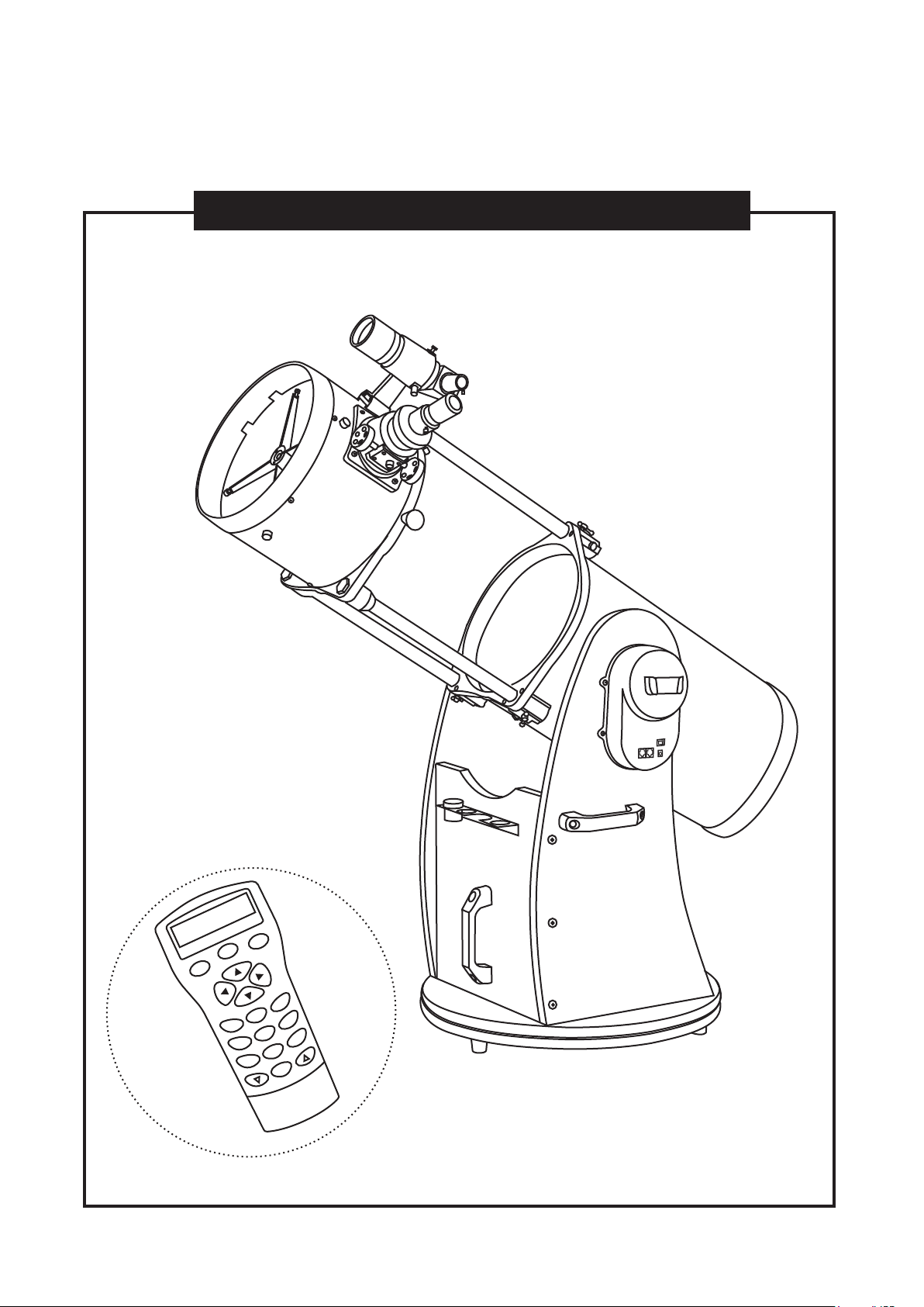
DOBSONIAN BASE ASSEMBLY
Parts List
PARTS
Round base assembly
Right side panel assembly
Left side panel assembly
Front panel
Eyepiece holder / Countersunk head Phillips screws
Feet /
Countersunk head Phillips screws (silver)
Handle
Reinforce board
Hex socket head cap screw M5x60
Large washer for M5 screw
Hex socket flat head screw 7x50
Hex socket head cap screw M8x25
Optical tube locking screw
Allen Wrenches (2mm, 4mm, 6mm)
Phillips screw driver
Fastening bolts and washers
8” and 10”
1pc
1pc
1pc
1pc
1pc / 3pcs
3pcs / 3pcs
3pcs
8pcs
8pcs
6pcs
6pcs
1pc
1pc each
1pc
12”
1pc
1pc
1pc
1pc
1pc / 3pcs
3pcs / 3pcs
3pcs
2pcs
8pcs
8pcs
12pcs
6pcs
1pc
1pc each
1pc
14” and 16”
1pc
1pc
1pc
1pc
1pc / 3pcs
3pcs / 3pcs
2pcs
2pcs
6pcs
4pcs
1pc
1pc each
1pc
12pcs each
4
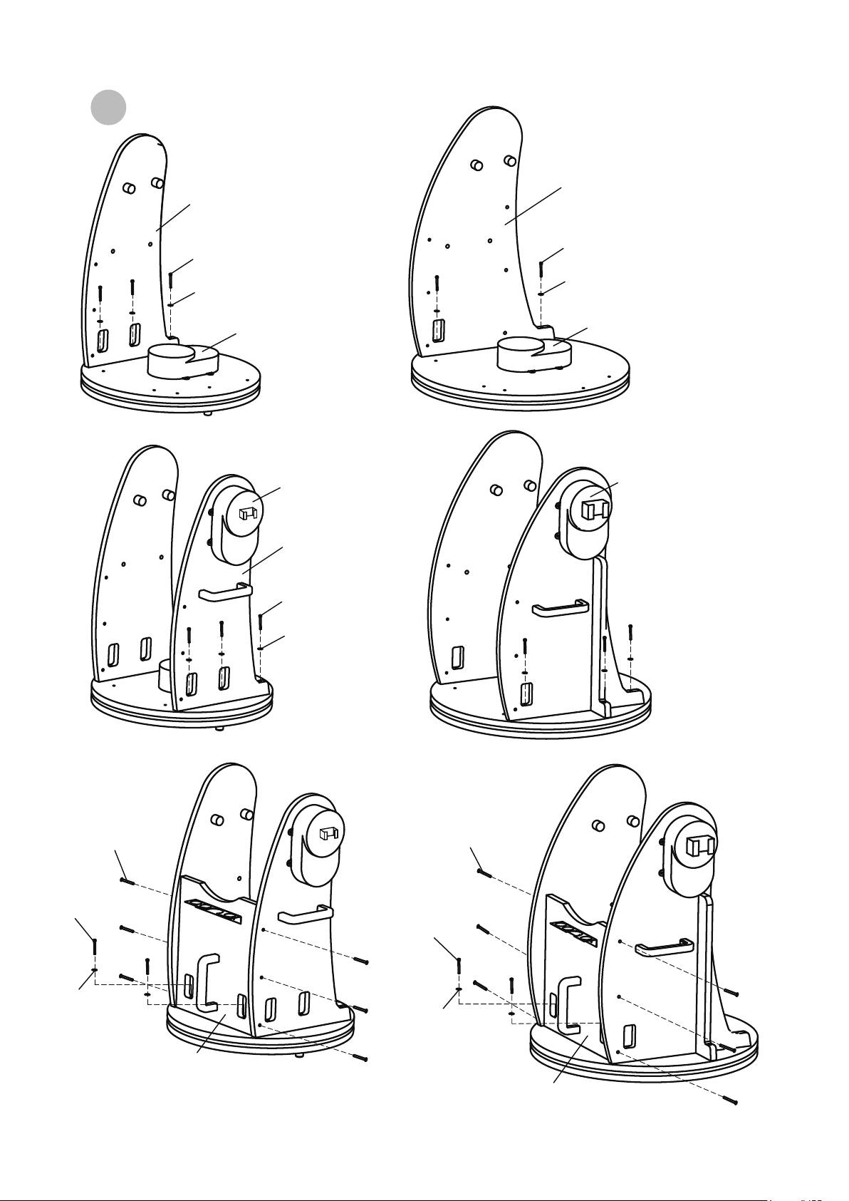
4
(12”)
Reinforce board
Hex socket flat head screw 7x50
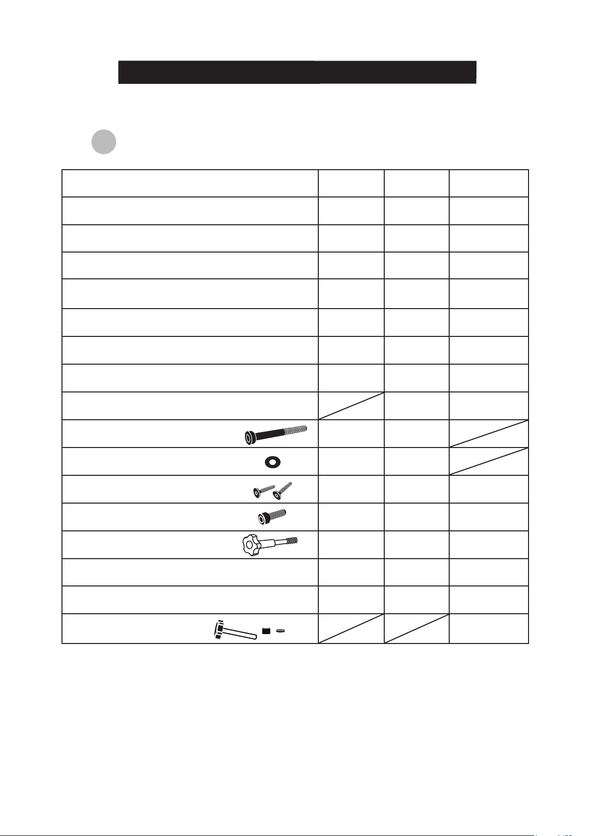
Side and front panel setup
R
ound base assembly setup
(8” and 10”)
Right side panel assembly
Handle
Right side panel
Eyepiece holder Front panel
Handle
Front panel
Right side panel assembly
Handle
Left side panel
Reinforce board
Hex socket flat head screw 7x50
Round base assembly (the bottom side)Foot
(12”)
Locate the hand control holder. Using the
two screws provided, attach the holder to the
latitude motor box.
(8” and 10”)
Locate the hand control holder.
Using the two screws provided, attach the holder
to the latitude motor box.
8”, 10”, and 12”
Flip the round base assembly over.
Attach the feet onto the assembly
using the Countersunk head
Phillips screws provided.
5
5
M
ount setup
(8” and 10”)
Right side panel assembly
Azimuth Motor box
Altitude Motor box
Altitude Motor box
Azimuth Motor box
Hex socket head cap
screw M5x60
Large washer for
M5 screw
(12”)
(8” and 10”)
(12”)
(8” and 10”)
(12”)
Right side panel assembly
Hex socket head cap
screw M5x60
Large washer for
M5 screw
Hex socket head
cap screw M5x60
Large washer
for M5 screw
Left side panel
assembly
Hex socket head
cap screw M5x60
Large washer
for M5 screw
Left side panel
assembly
Hex socket flat
head screw 7x50
Hex socket flat
head screw 7x50
Hex socket
head cap
screw M5x60
Large washer
for M5 screw
Front panel
Hex socket flat
head screw 7x50
Hex socket
flat head
screw 7x50
Large washer
for M5 screw
Front panel
Hex socket
head cap
screw M5x60
6
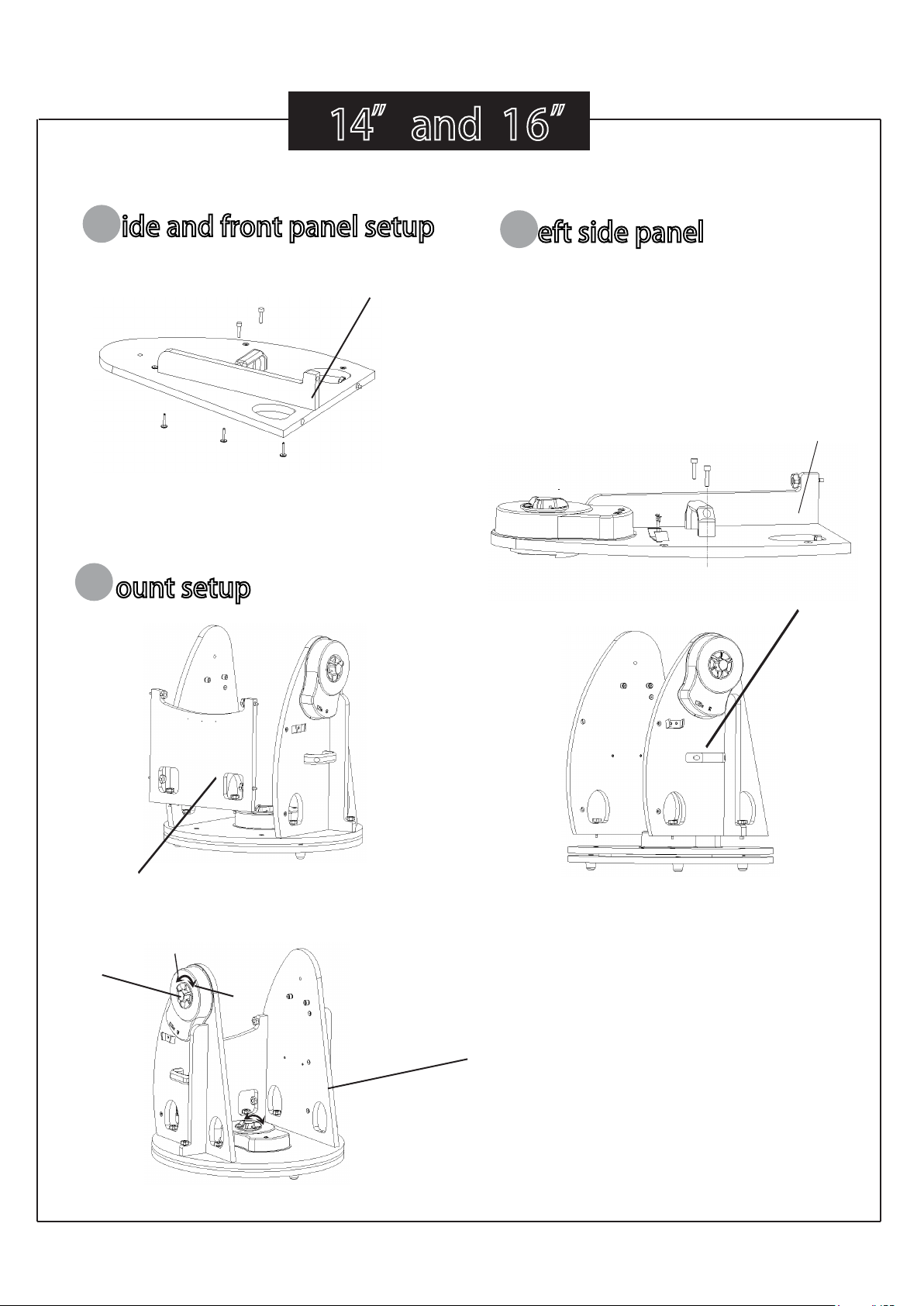
14”and 16”
S
ide and front panel setup
Right side panel
Reinforce board
Hex socket flat head screw 7X50
Reinforce board
Left side panel
assembly
When using GoTo and tracking
function , please tighten the
handwheel
Front panel
L eft side panel
M
ount setup
Locate the hand control holder.
Using the two screws provided ,
attach the holder to the Left side
panel assembly
handwheel
loose
lock
7
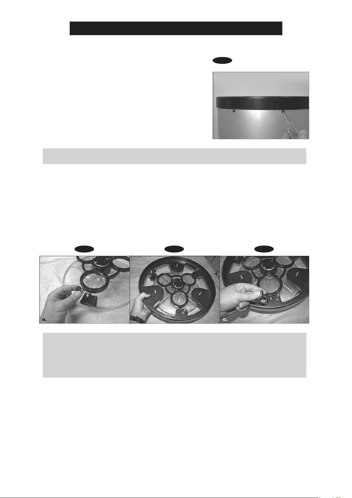
2. Before beginning to assemble the rear end ring to the mirror support cell, nd a clean, at surface
and place a clean cloth or towel on it. Turn the mirror cell over so that the mirror is facing downward
and then put it down on the cloth. Place the three springs onto the three exposed threaded shafts
(see Figure 2a). Lower the end ring onto the mirror cell so that the threaded shafts pass through it,
and the end ring rests on the springs (Figure 2b). Add a nylon washer to each collimation knob and
thread the collimation knobs through the end ring and onto the threaded shafts (Figure 2c). Conrm
that the knobs have at least three full turns of engagement on the shafts. The mirror and end ring
assembly is now all set to be installed onto the lower tube section.
Fig.1
1. When installing the mirror into the optical tube, you
must rst remove the rear end ring attached to the lower
section of the optical tube. Simply unthread and remove
the eight Phillips-head screws that connect the end ring
to the tube (Figure 1), and then pull the end ring off of
the tube.
Caution: The raw edge of the tube itself will be exposed
after the rear end ring is removed from the tube. Be
careful not to cut or injure yourself on the tube’s edge.
Please also be careful not to pinch your ngers when
attaching the assembled mirror cell onto the tube.
Figure 1. To remove the rear end ring, unthread the eight screws on the tube.
Figure 2. (a) Place the three springs on the exposed threaded shafts of the mirror cell (b) Lower
the rear end ring onto the mirror cell so that the threaded shafts of the mirror cell pass through
the end ring, and the end ring rests on the springs (c) Thread the collimation knobs, with nylon
washers attached, through the rear end ring and onto the threaded shafts. Check that the knobs
have at least three full turns of engagement on the shafts.
Fig.2a Fig.2b Fig.2c
PRIMARY MIRROR INSTALLATION

8
3. It can be a tricky task when assembling the end ring (and mirror cell) back onto the tube.
The complication is that the large diameter and thin metal of the tube will cause the tube to
become somewhat out of round once the end ring is removed. To assemble the rear end ring
(with mirror and mirror cell now connected) to the tube, position the lower section of the tube
up vertically so that the raw edge of the tube is up. Line up the threaded holes in the edge of
the end ring with the holes in the end of the tube. Then, lower the entire assembly onto the
tube. (Be careful to avoid nger pinching during this step.) There may be a bulge in the
perimeter of the tube that obstructs the end ring from fully seating onto the tube (Figure 3).
Simply press the bulge down and the entire mirror cell assembly should seat onto the tube.
Now, replace the eight Phillips screws that connect the rear end ring to the tube.
Fig.3
Figure 3. Find the area of tube that is bulg-
ing out and obstructing it from seating in
the end ring. Press on the bulge to force
the tube into the end ring.
9
7
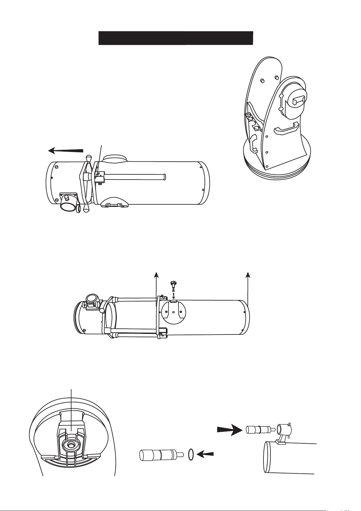
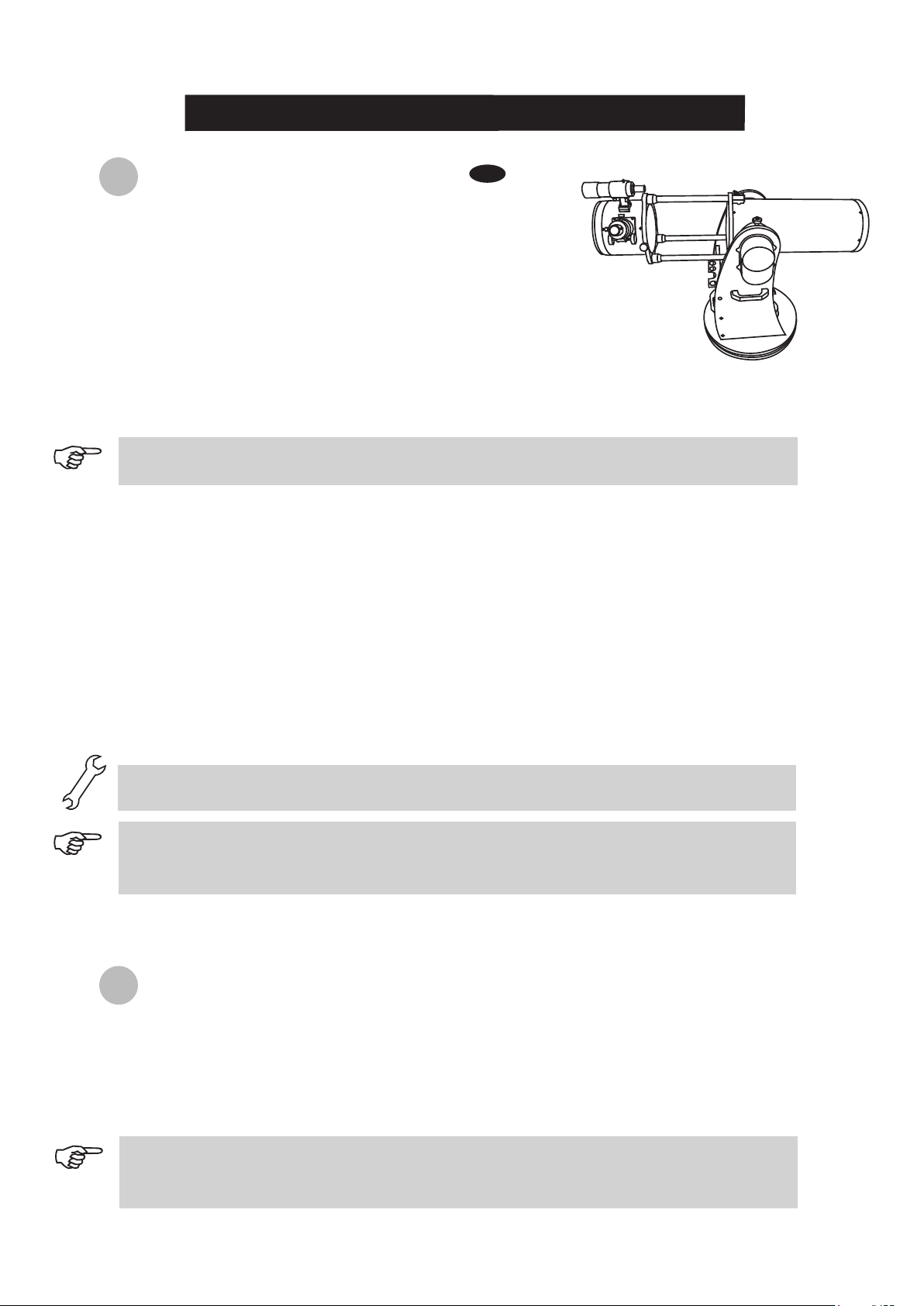
TELESCOPE SETUP
1.
2.
3.
Place the mount on the ground. Place a bubble level on
the top of the round base to ensure the mount is set on a
leveled plane. Better leveling will yield better tracking
performance.
To extend the telescope tube, loosen the three slider lock
screws and pull the top part of the telescope assembly
out until it clicks in place Tighten the slider lock screws.
Do not over-tighten.
Remove the dust cap and the protective cover in the front
of the tube.
4.
5.
6.
7.
8.
9.
Grab the telescope tube with both hands at the positions indicated in the diagram below.
Hold the telescope tube directly above the mount. Align the side bearings of the tube to the
mounting platforms on the inner side of the side boards. Lower the telescope tube and
carefully place it on the base.
Tighten the locking screw to secure the tube in place.
Loosen these screws
Lift up the telescope tube by holding here
Locate the finderscope bracket
and carefully remove the
rubber-o-ring from it. Position
the o-ring into groove on the
finderscope tube.
Slide the finderscope bracket
into the mounting slot and
tighten the screw to hold the
bracket in place.
(Straight through finderscope
shown here)
Loosen the two adjusting screws
on the bracket. Pull back the
spring-loaded screw and position
the finderscope into its bracket by
sliding it backwards until the rubber
o-ring seats.
Mounting platform. Make sure that
the side bearing aligns with this
when placing the tube on the mount.
Optical Tube
Locking screw
10
8
C
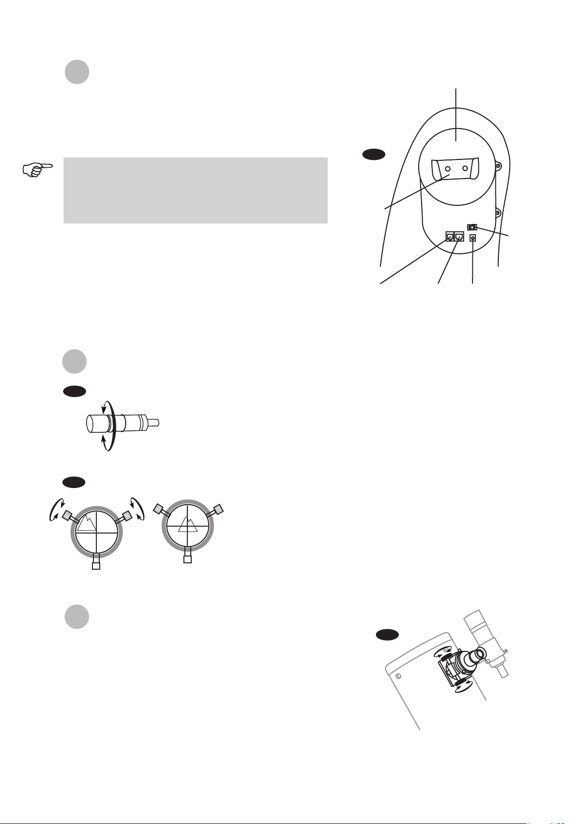
onnecting the cables
Power supply cable: The Dobsonian SynScan requires
12-Volts DC Nominal power. The power cable from the
battery pack or other power supply goes into the jack labeled
Power on the altitude motor box. (Fig.a).
AZ motor cable: This is the flat cable with 8-pin RJ-45 plug on
both end. Insert one end into the jack labeled "Az Motor" on
the altitude motor box and the other end into the azimuth
motor box on the round base.
Hand control cable: This is the coil cable with a 8-pin RJ-45
plug on one end and a 6-pin RJ-12 plug on the other. Plug the
RJ-45 end into the hand control (Fig.e) and the other end into
the outlet on the altitude motor box (Fig.a).
Fig.b
Fig.c
A
ligning the Finderscope
These fixed magnification scopes mounted on the optical tube are very useful
accessories. When they are correctly aligned with the telescope, objects can
be quickly located and brought to the centre of the field. Alignment is best
done outdoors in day light when it's easier to locate objects. If it is necessary
to refocus your finderscope, sight on an object that is at least 500 yards
(metres) away. Loosen the locking ring by unscrewing it back towards the
bracket. The front lens holder can now be turned in and out to focus. When
focus is reached, lock it in position with the locking ring (Fig.b).
Choose a distant object that is at least 500 yards away and
point the main telescope at it. Adjust the telescope so that
the object is in the centre of the view in your eyepiece.
Check the finderscope to see if the object centred in the
main telescope view is centred on the crosshairs.
Use the two small alignment screws to centre the
finderscope crosshairs on the object. The screws work in
opposition to a spring-loaded knob (Fig.c).
1.
2.
3.
(Straight through finderscope
shown here)
F
ocusing
Slowly turn the focus knobs (Fig.c), one way or the other, until the
image in the eyepiece is sharp. The image usually has to be
finely refocused over time, due to small variations caused by
temperature changes, flexures, etc. This often happens with short
focal ratio telescopes, particularly when they haven't yet reached
outside temperature. Refocusing is almost always necessary
when you change an eyepiece or add or remove a Barlow lens.
Fig.c
To avoid tangling of the power cable, the battery pack or
power tank can be placed on the round base, behind the
front panel. Pass the cable through the first hole on the
left side panel to plug into the power jack.
Fig.a
Hand control
cable goes here
Hand control
holder
Power switch
AZ motor cable
goes here
Power cable
goes here
Altitude motor box
11
I
ntroduction to the SynScan
TM
AZ
The SynScan
TM
AZ is a precision-engineered instrument that provides two different operation modes:
AUTO-TRACKING MODE
The Sky-Watcher Dobsonian SynScan telescope has a patented dual encoder design incorporated to
record the position of the telescope. Under the Auto-Tracking Mode, you may choose to manually, or
electronically, move the telescope to any position without deactivating the tracking mode first. After
moving to a new object, the telescope will automatically begin to track the new object accurately. No
re-setup is required in one observing session.
If you are familiar with the night sky, or if you wish to quickly set up the telescope for tracking the
object, AUTO-TRACKING MODE will allow you to operate the telescope in the traditional way with
added bonus of automatic tracking and digital setting circle.
AZ GOTO MODE
The AZ GOTO MODE provides extensive computerized GO-TO functions to assist you in finding and
enjoying the night sky treasures, such as planets, nebulea, star clusters, galaxies and much more.
The hand control allows you to point your telescope to a specific object or even tour the skies at the
touch of a button. The user friendly menu system allows automatic slewing to over 42,900 objects.
Even an inexperienced astronomer can master its variety of features in a few observing sessions.
SynScan
TM
AZ Hand Control
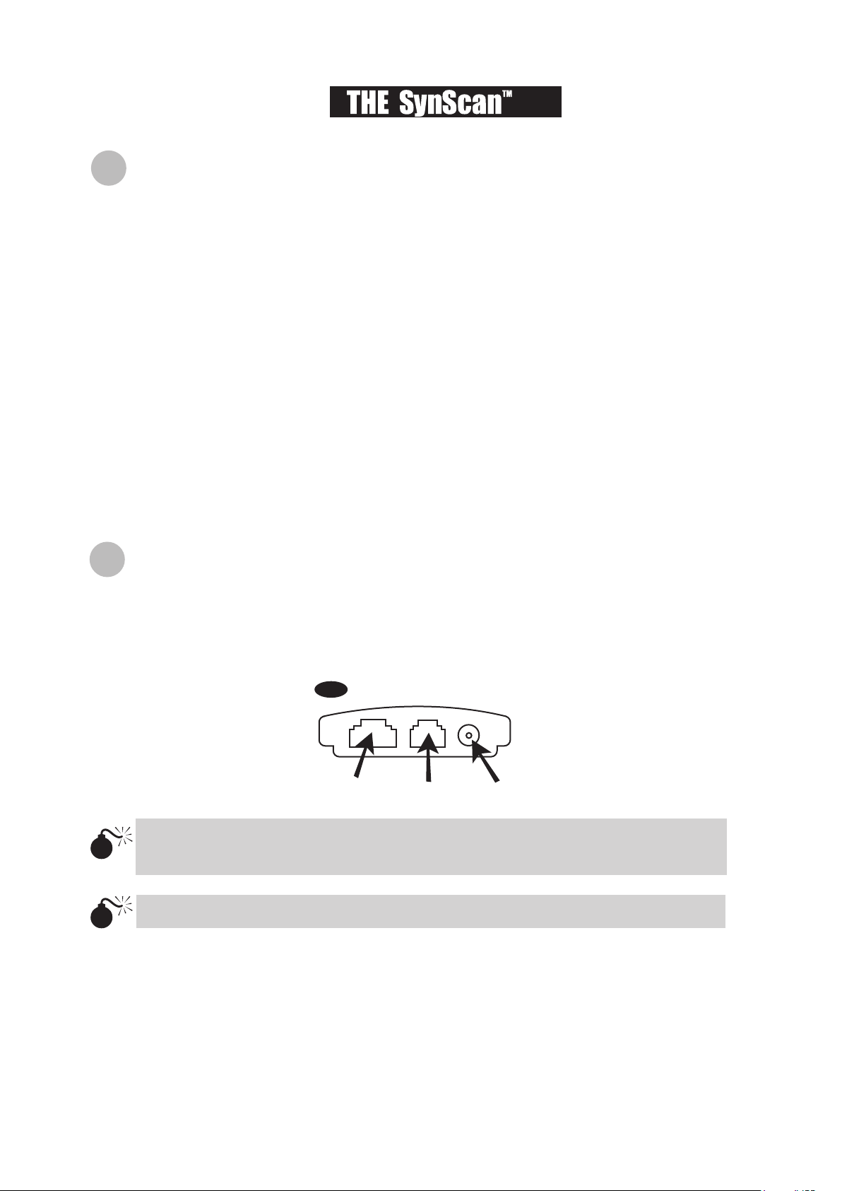
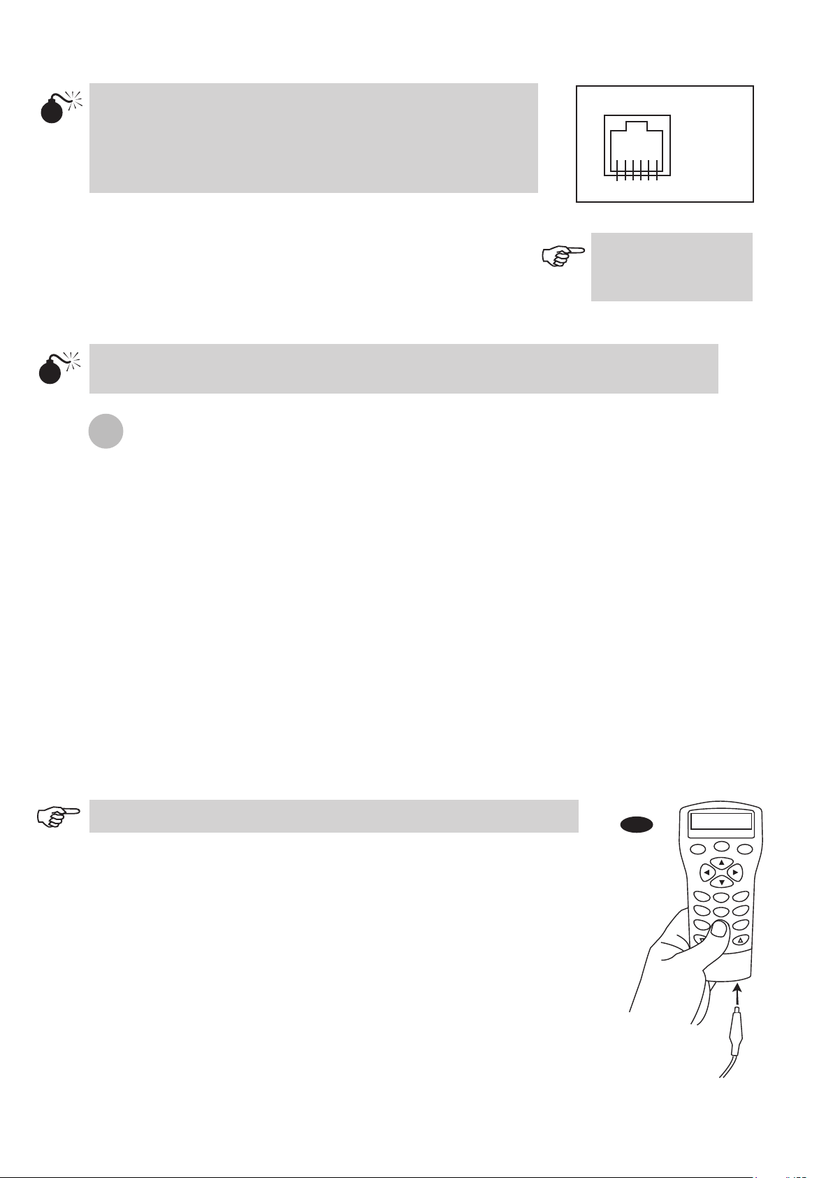
On the bottom of the hand control, the middle port is used for RS-232 communications between the
SynScan
TM
AZ and a computer or other devices. (See “Linking with a Computer” for details.) The DC
power port allows independent use of the SynScan
TM
AZ hand control for users who wish to browse
the database or update the firmware without connecting to the telescope (Fig.e).
9
Fig.e
RJ-45
RJ-12 DC power port
The DC power port on the hand control is for hand control stand-alone applications only. For
telescope applications, use the 12V DC outlet on the mount.
To connect the SynScan AZ to a PC, use only the RS-232 cable provided with the mount.
AZ
The SynScan
TM
AZ Hand Control allows direct access to all the motion controls of the telescope and a
database with a range of preset objects. The Hand Control comes with a dual-line, 16 character
display screen that is backlit for comfortable viewing of the telescope information and scrolling text. To
explore the many functions that the SynScan
TM
AZ has to offer, there are 4 main categories of control
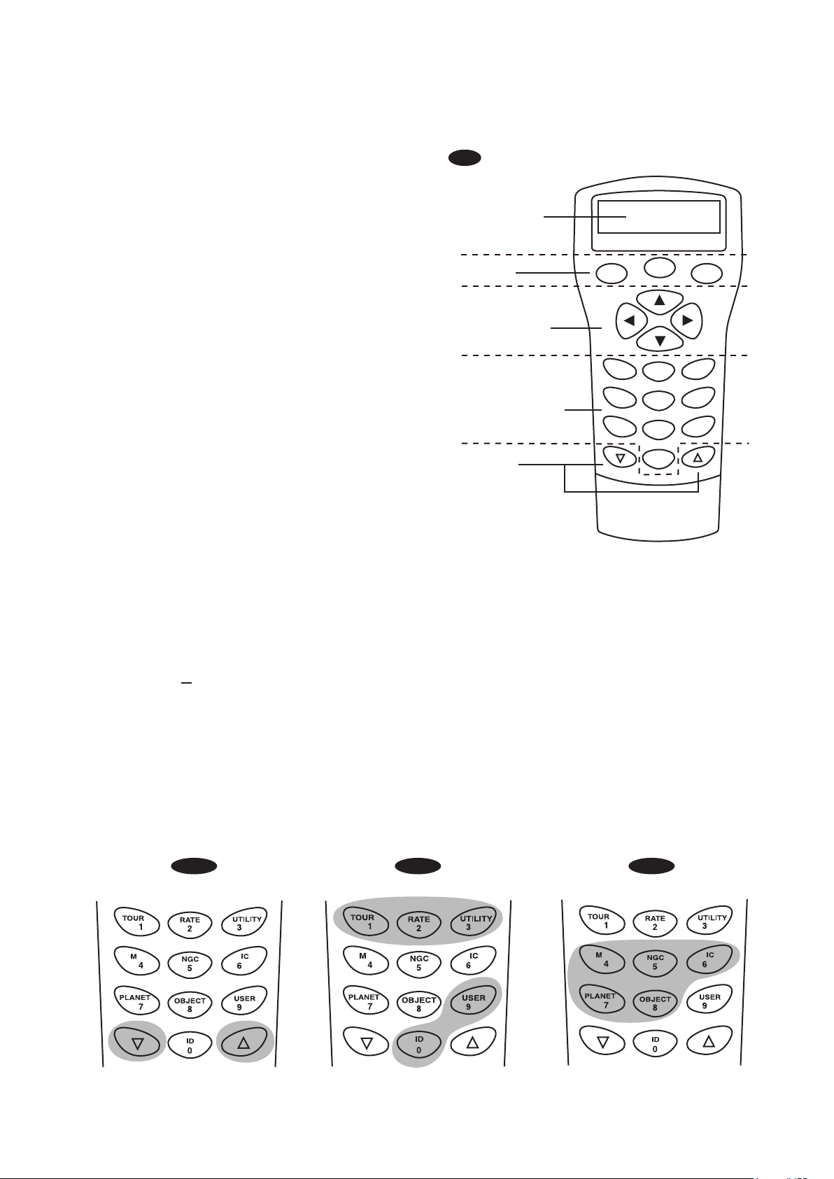
on the Hand Control (Fig.f):
12
10
Fig.g-1 Fig.g-2 Fig.g-3
Mode keys
Directional keys
The mode keys are located near the top, close
to the LCD display. They include the ESC,
ENTER, and SETUP keys:
ESC key is used to escape from a certain
command or to go back a level in the menu tree.
SETUP key is a quick hot key that takes you to
the Setup submenu.
ENTER key is used to select the functions and
submenus in the menu tree, and to confirm
certain functional operations.
The up and down scroll keys allow you to scroll up and down within the menu tree or selections.
The directional keys allow complete control of
the telescope at almost any step in the
SynScan's operation. These controls are
locked out when the telescope is slewing to an
object. They are normally used to initially align,
center objects in the eyepiece, and manual
guiding. The left and right directional keys can
also be used to move the text cursor when
entering data to the hand control.
Dual Purpose keys
Scroll Keys
(Fig.g-1)
These keys range from the middle to the bottom of the hand control. They serve two distinct
purposes data entry and quick reference hot keys.
TOUR key (Fig.g-2) takes you on a preset tour across the sky you are currently under.
RATE key (Fig.g-2) changes the speed rate of the motors when the direction keys are pressed.
There are 10 speeds to choose from: 0 (slowest) to 9 (fastest).
UTILITY key (Fig.g-2) shows functions such as Show Position, Display Time...etc.
USER key (Fig.g-2) gives access to up to 25 user-defined coordinates.
ID key (Fig.g-2) identifies the object the telescope is currently pointing to.
NGC, IC, M, PLANET, and OBJECT keys (Fig.g-3) allow direct access to SynScan
TM
database of
over 42,900 objects.
Fig.f
ESC
SETUP
ENTER
1
2
3
4
5
6
7
8
9
0
TOUR
UTILITY
RATE
M IC
NGC
PLANET
USER
OBJECT
ID
Display screen
Mode keys
Directional keys
Dual purpose keys
Scroll keys
13
11
AUTOTRACKING OPERATION
Make sure that the telescope is set on a level
ground. Point the telescope to the North.
Locate the altitude scale on the inside of the left side
board. Lower the telescope tube in altitude until it
reads 0. (Fig.h).
1.
2.
3.
4.
5.
6.
7.
8.
NORTH
Fig.h
The hand control's red light will become dimmer and the backlight of the key pads will turn off
if idle for 30 seconds. Pressing any key turns it back on.
The accuracy of the coordinate readings is dependent on the correctness of the setup. For best
result, make sure that the telescope is leveled and pointed to the North in the initial position. The
data entered into the hand control must be as accurate as possible.
Enter the telescope's current latitudinal and longitudinal coordinates using the numeric keypad. First
enter the longitudinal coordinate, followed by the latitudinal coordinate. Use the scroll keys to choose
between W or E, and N or S. Pressing the left or right directional keys will move the cursor to the
previous or next number. Press ENTER to confirm. The format you enter should look like this: 123 04’ W
49 09’N.
Enter your current time zone in hours and minutes (see Appendix C), using the scroll keys and numeric
key pad (+ for East, - for West). Press ENTER to confirm. The format you enter should look like this if
you are in Pacific Standard Time (PST): -08:00.
Enter the date in the following format mm/dd/yyyy using the numeric keypad. Press ENTER to confirm.
Enter your current local time using the 24 hr time mode (e.g. 2:00PM=14:00). Press ENTER to view the
time you just entered. If it is incorrect, press ESC to go back to the previous screen. If correct, press
ENTER again to confirm. After entering the current time, the SynScan
TM
AZ will prompt "DAYLIGHT
SAVING?". Use the scroll keys to make the selection and press ENTER to confirm. After setting the
daylight saving, SynScan
TM
will display "Begin alignment?". Press "2" to bypass the alignment procedure.
9.
Press SETUP and then use the scroll keys to browse to the “Auto Tracking >” sub-menu. Press
ENTER to enter the Auto-tracking mode.
Connect the hand control to the mount with the provided cable. Plug
the DC 12
volt power into the outlet of the mount. Turn on the power.
The initial screen displayed on the hand control is the Version Screen.
Press ENTER to proceed. The hand control will display a warning
concerning pointing the telescope at the sun without proper equipment.
If you have read the message already, pressing ENTER will bypass the
message and skip to the next step.
I
nitial Setup
If a mistake was entered into the SynScan
TM
AZ hand control, press the ESC key to go back to the
previous menu, and press
ENTER to start again.
When the power is on, you may choose to adjust the telescope electronically by using the hand
control or manually by pushing the tube. The telescope will calculate the coordinates
accordingly and display the information correctly on the hand control.
The telescope is now ready to point to any object and start tracking at the sidereal rate. The hand control
will display the coordinates of the direction the telescope is pointed. Press the scroll keys to switch
between the following three coordinate formats: Celestial, Terrestrial, and Telescope mount coordinates.
You may press ESC to exit from the Autotracking mode at any time during tracking to browse or choose
other functions provided by the SynScan
TM
AZ hand control. To return to the Autotracking mode, choose
“Auto-Tracking” under SETUP menu and press ENTER.
A
utomatic tracking

14
12
AZ GOTO OPERATION
I
nitial Setup
The hand control's red light will become dimmer and the backlight of the key pads will turn
off if idle for 30 seconds. Pressing any key turns it back on.
Make sure the mount is level to the ground.
Point the telescope roughly to the brightest star in the sky to your naked eyes.
Connect the hand control to the mount with the provided cable. Plug the DC 12 volt power into the
outlet of the mount to turn on the power. Flip the power switch to the “on” position.
The initial screen displayed on the hand control is the Version Screen. Press ENTER to proceed.
The hand control will display a warning concerning pointing the telescope at the sun without
proper equipment. If you have read the message already, pressing ENTER will bypass the
message and skip to the next step.
1.
2.
3.
4.
5.
6.
7.
8.
9.
Enter the telescope's current latitudinal and longitudinal position using the numeric keypad.
First enter the longitudinal coordinate, followed by the latitudinal coordinate. Use the scroll
keys to choose between W or E, and N or S. Pressing the left or right directional keys will
move the cursor to the previous or next number. Press ENTER to confirm. The format you
enter should look like this: 123 04’ W 49 09’N.
Enter your current time zone in hours and minutes (see Appendix C), using the scroll keys
and numeric key pad (+ for East, - for West). Press ENTER to confirm. The format you enter
should look like this if you are in Pacific Standard Time (PST): -08:00.
Enter the date in the following format mm/dd/yyyy using the numeric keypad. Press ENTER
to confirm.
Enter your current local time using the 24 hr time mode (e.g. 2:00PM=14:00). Press ENTER
to view the time you just entered. If it is incorrect, press ESC to go back to the previous
screen. If correct, press ENTER again to proceed to the daylight saving setting.
If a mistake was entered into the SynScan
TM
AZ hand control, press the ESC key to go back to
the previous menu, and press ENTER to start again.
After setting the daylight saving, SynScan
TM
will display "Begin alignment?". Press "1" to start
the alignment procedure.
10.
Star Alignment
In order for the SynScan
TM
AZ to correctly point to objects in the sky, it must first be aligned to two to three
known positions (stars) in the sky. As the Earth rotates on its axis every 24 hours, astronomical objects
appear to move through the sky following an arc. With the supplied information, the telescope can
replicate a model of the sky and the movements of astronomical objects. Star alignment can be done
anytime during the observing session by choosing Alignment under Setup Mode, in the Main Menu.
There are two ways to align the SynScan
TM
AZ Brightest Star alignment and 2-Star alignment. If
you are using the SynScan
TM
AZ for the first time, and you are not familiar with the celestial object in
the sky, we recommend that you begin with the Brightest Alignment. The Brightest Star alignment will
prompt and help you find the brightest star of a specific direction in the sky at your current site. It is
convenient for user to identify the brightest star in the sky. Before performing the alignment method,
make sure that your finderscope is well aligned with the telescope tube. See the next page for tips on
how to choose the alignment stars. Below describes a step-by-step procedure on how to perform the
Brightest Star Alignment:
15
13
S
yn
Scan
TM
AZ will beep once when it has
finished slewing to an object. Do not try to
adjust the telescope before you hear the beep.
S
yn
Scan
TM
AZ will only respond to the ESC
key while slewing.
To ensure the accuracy of the star
alignment, make sure to end the
movement with the UP or RIGHT
directional key when centering the
object in the eyepiece view.
Brightest Star Alignment
1.
2.
Once the directional division has been selected, the hand control will generate a list of the stars located
within this region that are brighter than 1.5 in magnitudes, starting from the brightest to the dimmest.
The stars and planets below 10 degrees, higher than 75 degrees in elevation or fainter than 1.4 in
magnitudes will be filtered out.
The name and magnitude of the alignment star will be displayed on the first line of the LCD. The
approximate position will be prompted on the second line. For example, if Arcturus is prompt as
alignment star, its magnitude is 0.0 and location is at 88.1 degree east and 24.1 degree above the
horizon. You will see the LCD display as shown in Fig.i.
3.
4.
Directional division Span range in azimuth
The northern sky 315 ° ~ 45 °
The northeast sky 0 ° ~ 90 °
The eastern sky 45 ° ~ 135 °
The southeast sky 90 ° ~ 180 °
The southern sky 135 ° ~ 225 °
The southwest sky 180 ° ~ 270 °
The western sky 225 ° ~ 315 °
The northwest sky 270 ° ~ 360 °
Find a visible single bright star that is far apart from any object in the sky. Point the telescope roughly
to the star.
In the alignment screen, select Brightest-Star Align using the scroll keys. Press ENTER to confirm. The
hand control will prompt "Select Region:" for you to select one of the eight directional divisions in
azimuth angle from the north, northeast, east, southeast to northwest etc. Select the region where the
chosen star is located and press ENTER.
Each division covers 90-degree span in azimuth. The table below explains the range of the eight
directional divisions.
This alignment method is the most suitable if you are unfamiliar with the night sky, or are unsure of the name
of the brighter stars.
1. Arct u rus 0.0
E 88.1 ° 24 . 1°
For the first alignment star, the mount will not slew to the star auto-
matically. Use the directional buttons to manually slew the telescope
to point to the object in the finder and then center it in the eyepiece.
You may change the slewing speed by pressing the RATE button,
and then choose a number between 0 (slowest) - 9 (fastest). You will
find that Rate 4 may be best suited for centering the object in the
finderscope and Rate 3 or less for centering in the eyepiece view.
Once the star has been centered in the eyepiece, if it is a planet the hand control will prompt you to rese-
lect a star from the list as the first alignment star. Otherwise the hand control will prompt a list of objects
for you to choose as the second alignment star. Select an object from the list. The hand control will com-
mand the mount to slew the telescope to point to the star. If you see multiple objects in the eyepiece
view, the chosen star should be the brightest among all. Center the star in the eyepiece again. If both
alignment stars are properly aligned, "Alignment Successful" will display on the LCD. Otherwise, the
warning "Alignment Failed" will show and the alignment will have to be done again. You may exit the
alignment procedure by pressing the ESC key anytime during the procedure.
Fig.i
6.
5.
The slewing speed can be
adjusted by pressing on the
RATE button. Then choose a
number between 0 (slowest) - 9
(fastest).

16
14
The result of the star alignments is stored in the hand control even after the power has been shut off.
You will only need to perform the star alignment once as long as these two criteria are met: 1. The
telescope has been properly parked to one of the three Park Scope positions before turning off the
power. 2. The telescope setup, including the mount, has not been moved. Accessory change is
acceptable as long as it is done with great caution. When the hand control is turned on for the next
time, make sure to choose YES when prompt whether to start from the park position. The time
entered during initial setup should be based on the same source as last time. For example, if you
enter the time on your watch during this observing session, the time you enter next time should also
be read from your watch.
P
ointing Accuracy Enhancement (PAE)
1.
2.
3.
4.
In the alignment screen, select 2-Star Align using the scroll keys. Press ENTER to confirm.
The SynScan
TM
AZ will provide a list of stars available in your current sky for you to choose as the
first alignment star. Using the scroll keys, choose a star you are most familiar with and press
ENTER. The telescope will not automatically slew to the first selected alignment star. Use the
directional buttons to manually slew the telescope to point to the object. Now look through the
eyepiece and adjust the telescope so that the object is centered in the field of view of the
eyepiece. Press ENTER to confirm. You will find that Rate 4 may be best suited for centering the
object in the finderscope and Rate 3 or less for centering in the eyepiece view.
SynScan
TM
AZ will now provide a list of objects for the second alignment star. Choose a star using
the scroll keys and press ENTER. The telescope will start slewing towards the chosen object.
When the slewing stops, adjust the telescope with the directional keys until the star is centered on
the crosshairs in the finder scope. Repeat the centering procedure to center the object in the field
of the eyepiece and press ENTER to confirm.
If both alignment stars are properly aligned, "Alignment Successful" will display on the LCD.
Otherwise, the warning "Alignment Failed" will show and the alignment will have to be done again.
1.
2.
From a sky chart or a planetarium software, choose a bright object in the same area that you would
like to perform the PAE in. This object should be a known object that is easy to identify.
Find this PAE object in the SynScan hand control database and go-to the object. If your mount is
under the control of a planetarium software, click on the object to slew to it.
Two-Star Alignment
The two star alignment procedure is similar to the Brightest Star alignment, except that the hand control
will not prompt for you to select a directional region for a bright star. Below describes a step-by-step
procedure on how to perform the Two-Star Alignment:
After the star alignment, select an object in the object list and slew the telescope to the object in the sky.
If you notice pointing error after slewing the telescope to the object, you may use the Pointing Accuracy
Enhancement (PAE) to further improve the accuracy in the specific area where the object is located. The
PAE function will only correct the pointing error in the 5-degree spanned area of the chosen star. Other
regions of the sky will not be affected.
The PAE function also makes it easier to find deep-sky objects that are too dim to spot. This can be
done by selecting a bright object nearby to perform the PAE. Once the pointing accuracy of the specific
area is enhanced the telescope will be able to accurately place the dim deep-sky object near the center
of the eyepiece view.
Other than bright named stars, you may also choose planets or objects in the Messier, NGC, or IC
catalog as the PAE object.
Follow these steps to perform the PAE:
Following is some pointers on how to choose appropriate alignment stars:
Select two stars that are at least 60 degrees apart in Azimuth. The more distance between the two align-
ment stars, the better accuracy the alignment will produce. Choosing two stars with similar altitude will
also create a better result.

17
15
3.
After slewing to the object, press ESC to exit from the object catalog. Press the Utility button to enter
to the Utility menu. Choose PAE under the utility menu and press ENTER.
4.
5.
The hand control will display “Re-centering obj” and the name of the PAE object will appear in a
blinking mode (3 times). If the PAE object is selected from a planetarium software the hand control will
display “Last goto object” instead of the name.
Use the directional keys to adjust the telescope so that the PAE object is in the center of the eyepiece.
Press ENTER to record the result or press ESC to abort the operation if you do not wish to keep the
result. Upon pressing the ENTER key, the SynScan
TM
will record the amount of displacement and
automatically compensate the pointing error for this particular region in the sky.
The SynScan hand control provides a short cut to quickly activate the PAE function. After exiting from
the object catalog, instead of using the Utility menu, press and hold down the ESC key for 2 seconds.
The result for PAE is stored in the hand control even after the power has been shut off. You will
only need to perform the star alignment once as long as these two criteria are met: 1. The telescope
is moved to its home position (Park the telescope) before turning off the power. 2. The telescope
setup, including the mount, has not been moved. Accessory change is acceptable as long as it is
done with great caution. When the hand control is turned on for the next time, make sure to choose
YES when prompt whether to start from the park position. The time entered during initial setup
should be based on the same source as last time. For example, if you enter the time on your watch
during this observing session, the time you enter next time should also be read from your watch.
18
16
S
electing an Object
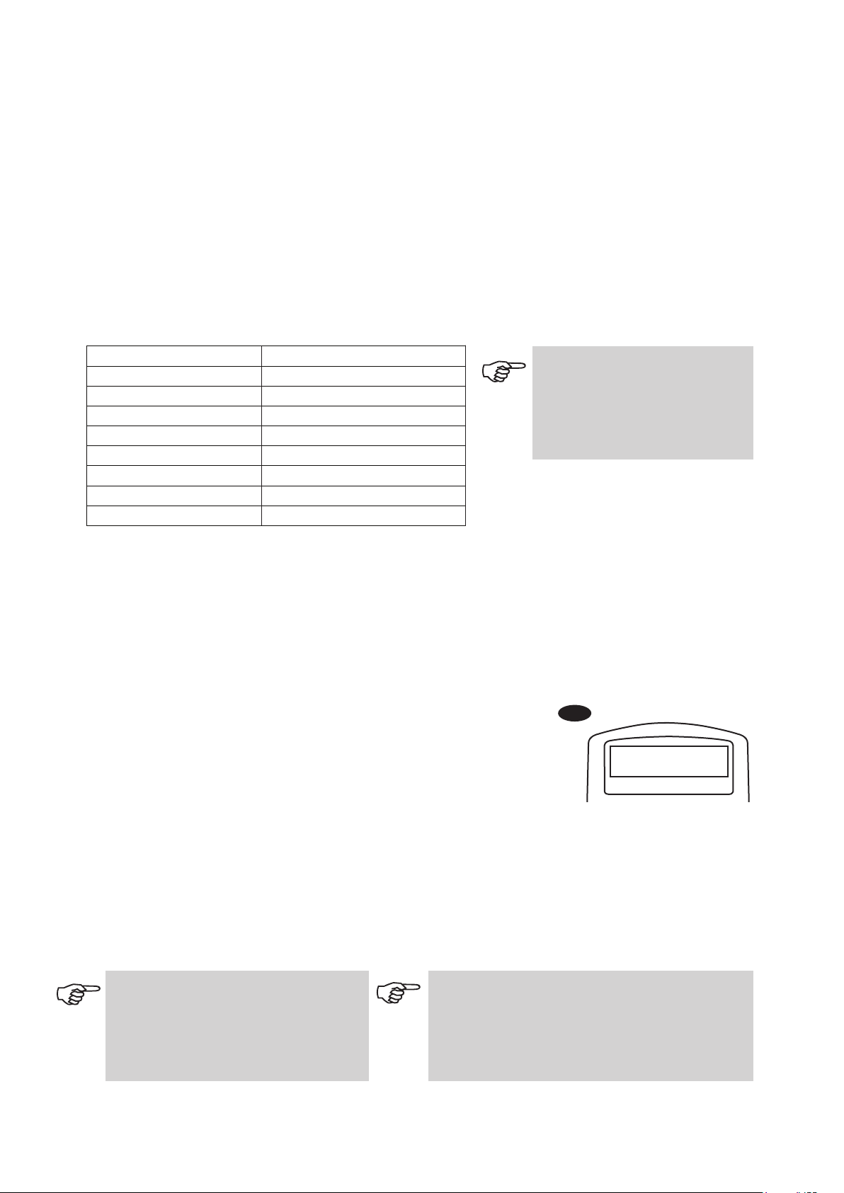
O
bject database in the SynScan
TM
AZ
Solar System - The other 8 planets of our solar system, plus the Moon.
Named Star - A list of 212 best known stars from the SynScan
TM
AZ database.
*NGC - 7,840 of the brightest deep sky objects from the Revised New General Catalog.
IC - 5,386 of standard stars and deep sky objects from the Indexed Catalog.
Messier - Complete list of 110 Messier objects.
Caldwell - Complete list of 109 Caldwell objects.
Double Stars - Includes 55 well-known double stars.
Variable Stars - Includes 20 will-known variable stars.
SAO - Includes 29,523 stars.
Once the telescope has been aligned. You can now access and view the 42,900 different objects
in the SynScan
TM
database. There are three methods of selecting a celestial object to view:
TOUR - Takes you on a preset tour across your current sky. It
will automatically choose from the database the brightest and
most beautiful deep-sky objects for your viewing pleasure. Use
the scroll keys to view through the deep sky objects. Choose the
desired object by pressing ENTER. It will show the coordinate of
the chosen object. Use the scroll keys to view other information
such as magnitude, size and constellation. Pressing ENTER
once more will cause the telescope to slew to the object.
M, NGC, IC - These shortcut keys give you access to the most
popular celestial catalogues to date. Each Catalog has a set
number of objects to choose from. Use the numeric keys to
select an object by entering its number. Pressing ENTER will
display its coordinate. Primary information such as size,
magnitude, and constellation are obtained by pressing the scroll
keys. Pressing ENTER once more will cause the telescope to
slew to the object.
PLANET - This shortcut key takes you straight to the Planets
sub menu in the database. Use the scroll keys to scroll through
the list of planets in our solar system. Press ENTER to view its
coordinates, and ENTER once more to slew to the planet.
USER - This will take you to the database that you have defined
for yourself. You can enter a new location or recall the objects
that have been previously saved (see Using the User Defined
Database).
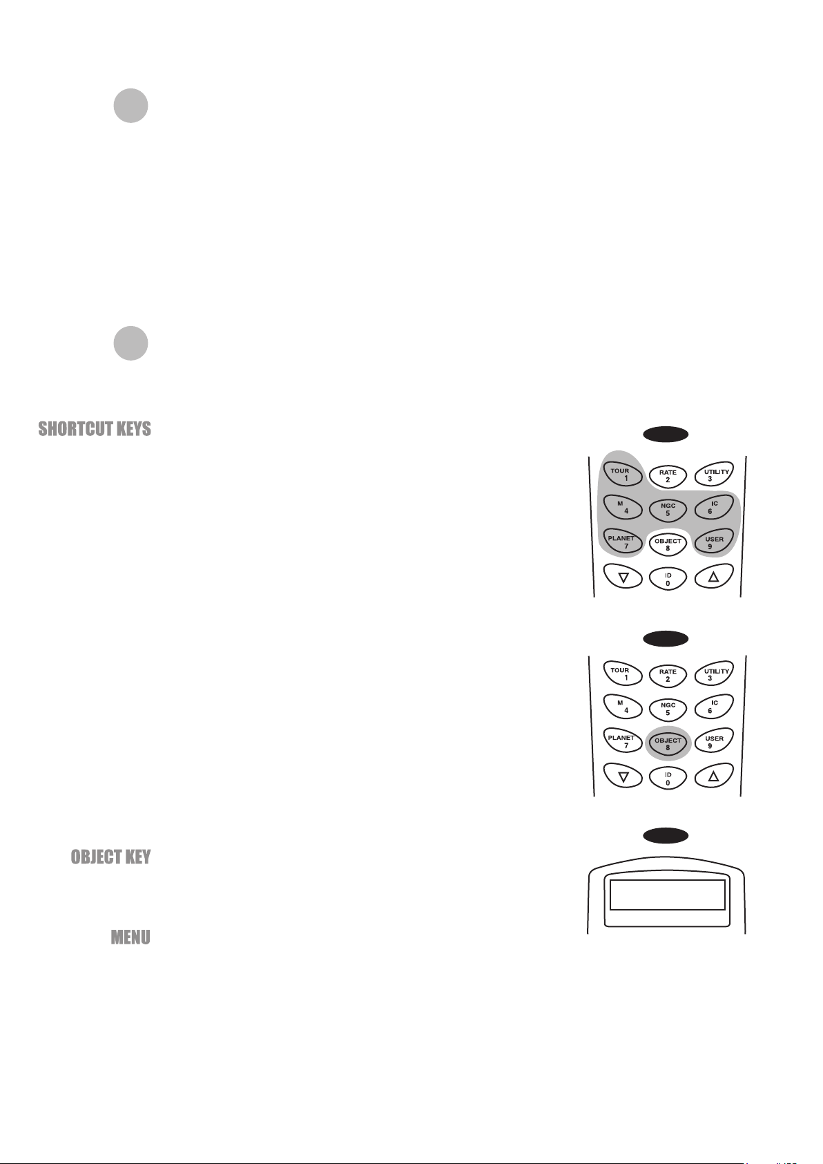
The OBJECT key takes you to the Objects Catalogue, where
you have complete access to over 42,900 celestial objects in the
database. (See Object database in the SynScan
TM
AZ and the
menu tree.)
In the Main Menu, scroll down to OBJECT CATALOG and press
ENTER. Similar to the OBJECT key, this gives you the complete
access to all 42,900 celestial objects in the database. (See
Object database in the SynScan
TM
AZ and the menu tree.)
The SynScan
TM
AZ comes with a vast database with over 42,900 objects coordinates and
information all available in the palm of your hand. The database contains the following catalogs:
OBJECT CATALOG
*NGC 2000.0 database, edited by Roger W. Sinnott, copyright by Sky Publishing Corporation. Used with permission.
(Fig.j-1)(Fig.j-1)
(Fig.j-2)(Fig.j-2)
(Fig.j-3)(Fig.j-3)
Fig.j-1
Fig.j-2
Fig.j-3

19
17
Utility Functions
Utility Functions are useful tools that provide simple, one-step processes to your SynScan
TM
AZ.
Show Position - This displays the coordinates of the location where the telescope is
currently pointed. The coordinates can be displayed in Dec and RA, Alt and Azm, or Ax1 (the
angular reading of the elevation) and Ax2 (the azimuth axes of the mount). Use the scroll
keys to choose your desired reading.
Show Information - Under this submenu, you may check local time, local sidereal time,
hardware, firmware and database version of the SynScan hand control. If the hand control is
connected to the mount, this menu will also display the firmware of motor control board.
Park Scope - The Park Scope function is useful when you prefer to have the telescope
start from a certain position for your next observing session. No star alignment will be
required in your next observing session as long as the telescope has not been moved.
There are three options to park your telescope:
PAE - Pointing Accuracy Enhancement. See page 13 for information.
Clear PAE data – This function clears all PAE data stored in the hand control.
GPS – This allows you to obtain information from the optional SynScan
TM
GPS receiver.
PC Direct Mode – The PC Direct Mode is used for updating the firmware of the motor
control board. It allows direct communication between the computer and the motor control
board of the mount.
Time - This displays the local time and the local sidereal time.
Version - This displays the hardware, firmware and database version of the SynScan
TM
AZ
hand control. This menu also displays the firmware version of the motor control board, if
the hand control is connected to the mount. Use the scroll keys to scroll up or down to
view the version numbers.
Temperature – This displays the temperature detected from the thermal sensor in the
hand control in both Celsius and Fahrenheit.
Power Voltage – This displays the power voltage detected from hand control in Volts.
HOME position - This is the position where both Ax1 and Ax2 reads 0. If you have done
the star alignment for GoTo operation or followed the initial setup for autotracking
operation, the HOME position of your telescope should be North facing and the tube
parallel to the ground.
CURRENT position - This is the position where the telescope is currently pointed.
CUSTOM position - This is the position where the telescope was previously parked
before the power was last turned off. This option is useful when you prefer to always start
the telescope from a certain position other than the HOME position.
S
etup Functions
Daylight Savings - Allows you to change the Daylight Savings option.
Alignment - Allows you to perform the star alignment.
Alignment Stars -
The Setup functions allow you to change any system variable or information regarding location,
time, date, and alignment configurations. To access the Setup Functions, either press SETUP key
on the key pad or scroll to SETUP under menu option using the scroll keys. Below lists the
different types of functions available to you, and their purposes.
Date - Allows you to change the date entered at the initial setup.
Time - Allows you to change the current time.
Observing site - Allows you to change the current location.
Auto Select - When this option is chosen, the hand control will filter out the star not
suitable for star alignment.
Sort by - This allows the hand control to generate a list of alignment stars and display
them alphabetically or by their magnitude.
Backlash - This feature allows you to insert a value for each axis to compensate for its backlash.
For better pointing accuracy, it is important that the backlash value is set to be equal or greater than
the real amount of backlash between the gears. The default setting of the backlash is 0 d 00' 00" (0
degree, 0 arcmin. and 0 arcsec.). Use the numeric keys to enter the desired value and press the
20
18
Auto Tracking - Allows the telescope to automatically track a celestial object without star
alignment. The hand control will display the coordinates of the direction the telescope is pointed at.
You may press the scroll keys to switch the coordinate to a different mode.
Set Slew Limits - Allows you to set the slewing limits of the mount on altitude axis. Setting the slew
limit prevents the optical tube from colliding with mount. To set the slew angular limitations in
altitude, use the numeric keys to enter the degrees and the RIGHT or LEFT keys to move the
cursor. The slew limit range is dependent on the mount and the optical tube installed on the mount.
Re-align Encoder - There are two encoders built in each axis of the Sky-Watcher Dobsonian Pro
mount. One encoder is coupled to the axis shaft and the other coupled to the motor shaft. This dual
encoder design (US Patent #: 7,228,253) allows you to manually move the telescope by hand any
time without losing the count on the axis encoder as long as the power is on. This enables the
Dobsonian to perform the Go-To and Autotracking functions to a certain degree of accuracy.
However, since the encoder at the axis shaft has lower resolution than the encoder coupled on the
motor shaft, you may need to calibrate the encoders from time to time to secure Go-To accuracy.
Following these steps to re-align the encoders:
Sid. Rate: This activates tracking in Sidereal rate (Dual Axes Tracking).
Lunar Rate: This activates tracking in Lunar rate (Dual Axes Tracking).
Solar Rate: This activates tracking in Solar rate (Dual Axes Tracking).
Stop Tracking: This stops the tracking instantly.
RIGHT directional key to move the cursor to the next digit. First set the value for R.A. Press
ENTER to proceed to Dec.
Tracking
Handset Setting - This submenu allows adjustments of the brightness of the LCD backlit, the
darkness of the LCD lettering, the brightness of the LED backlit and the beeper volume. Press the
RIGHT or LEFT directional key to increase or decrease the value.
Factory Setting - This submenu allows you to reset the hand control to its default setting.
The slew limit can be set any time but it will come into effect only until the star alignment has
been performed.
1.
2.
3.
4.
Choose Re-align Encoder under SETUP menu. Press ENTER to start.
The hand control will prompt you the two alignment starts chosen during the previous
star-alignment procedure. Use the scroll keys to select one of them and press ENTER to confirm.
The telescope will slew to the selected reference star. Use the directional keys to put the star in
the center of the eyepiece field. Press ENTER to confirm.
The hand control will prompt “Re-align Encoder completed.” on the LCD screen. Press ENTER to
confirm and finish the Re-align Encoder procedure.
The accuracy of the SynScan system depends heavily on the initial set up and star alignment. If you
notice inaccuracy in the Go-To performance, make sure that the initial set up and star alignment are
done correctly before considering re-aligning the encoders.
Find the User Objects under the Object Catalog. Press ENTER.
1.
Choose Edit Object by using the scroll keys. Press ENTER.
The SynScan™ AZ hand control stores the user-defined objects in two
formats - RA-Dec and AzAlt. Choose your desire format by pressing 1
for RA-Dec or 2 for Alt-Azimuth.
1.
2.
Saving an object to the database
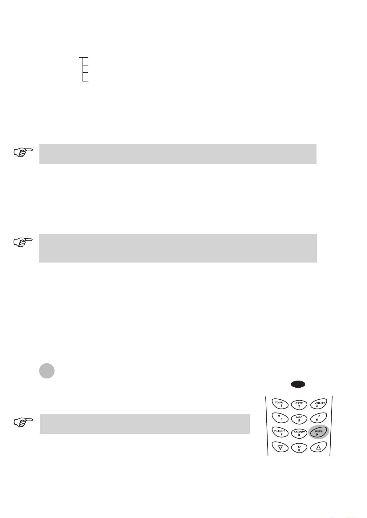
Using the User Defined Database
SynScan
TM
AZ allows you to save up to 25 objects in the user defined database.
Fig.k
The User Defined menu can also be accessed by pressing the quick
reference hot key “USER” (Fig.k).
21
19
The SynScan™ AZ hand control will display the coordinates where the
telescope is currently pointed at in your desired format. See Fig.l for an
example of the RA-Dec readout. If this is the location you would like to
save, simply press ENTER to record the coordinates. You may also
change the coordinates using the numeric keypad to enter numbers and
the scroll keys to choose between “+” and “-”. The RIGHT or LEFT
directional keys will move the cursor to the next or previous digit. Press
ENTER to save once you have entered the new coordinates.
1.
After the coordinates have been saved, the hand control will display an
User Object number as shown in Fig.m. Use the scroll keys to change to
the number you wish to represent the coordinates and press ENTER.
The SynScan
TM
AZ will display "View Object?" and the User Object
number you just entered. Press ENTER to go to the object or ESC to
return to the Input Coordinate menu.
2.
3.
Fig.l
Ent e r RA - DEC:
22h 4 6.1m +90 00
If the coordinates entered do not exist, the AZ SynScan hand control will not
respond when the ENTER key is pressed. Check the entry for mistake and
enter the correct coordinates.
Fig.m
Sav e ? <E N TER>
Use r obj . # 03
The User Object number displayed may not be a vacant one. If you are unsure which numbers are
vacant, it is recommended that you first check for the available numbers by recalling the saved
user objects.
Find the User Objects under the Recall Object. Press ENTER.
Use the scroll keys to browse through the User Object number until the number representing the
object you wish to view is present. Press ENTER to view its coordinate. Press ENTER again if
you wish to view the object. The telescope will start to slew to the object upon confirmation. The
hand control will not respond if a vacant User Object number is selected. Use the scroll keys to
choose another number and try again.
1.
2.
Recalling an user defined object
If the recalled object is below horizon, the SynScan
TM
AZ hand control will display "Below
Horizon !!" and automatically return to the Recall Object menu.
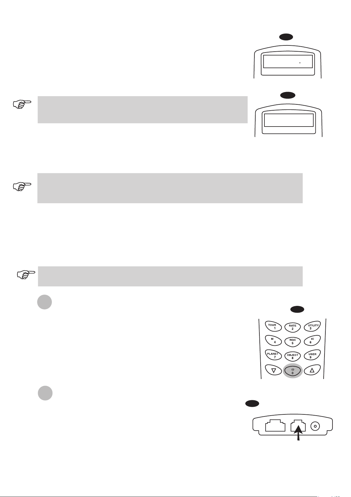
I
dentifying an Unknown Object
SynScan
TM
AZ has the ability to identify the unknown object the telescope is
currently pointing at. To do so, simply:
Press the ID key (Fig.n) or scroll down to IDENTIFY in the main menu
and press ENTER to identify the object.
The hand control will display a list containing the closest known object in
each M, IC, NGC, and Named Star catalogs and its distance to the
exact location where the telescope is pointed. Use the scroll keys to
view these objects.
Press ESC to exit from this function.
1.
2.
3.
Fig.n
Linking with A Computer
Another feature of SynScan
TM
AZ is the ability to connect to a computer via a serial
communication cable. Many commercially available planetarium softwares can
be used to control SynScan
TM
AZ. SynScan
TM
AZ Version 3.00 and later is
compatible with Celestron 5i/8i and NexStar GPS command protocol.
Make sure that the telescope has been aligned.
Connect the RS-232 cable to the RJ-12 connector on the hand control
and to the COM-port of your computer (Fig.o).
1.
2.
Fig.o
RJ- 12
Hand Control
22
20
3.
4.
Do not use RS-232 cable other than the one provided to connect
between the hand control and your computer. It may damage your
computer or the hand control. If you are making your own cable based
on the information provided in Appendix B, make sure that only pin 2, 3
and 5 connect to the com connector on your computer.
Do not disengage the SynScan AZ unit before you disengage the program. Doing so may cause
some programs to freeze.
1= EXPD+
2= TD
3= GND
4= EXPD-
5= RD
6= +12V
RJ-11 Pin-outs
6 5 4 3 2 1
In the planetarium software of your choice, choose "Sky-Watcher
Mount, Celestron NexStar 5i/8i" or "Celestron NexStar 8/9/11" in
the driver setup menu and follow the instructions provided by
your program to establish the connection to the telescope. The
SynScan
TM
AZ should be under the full control of your computer
once the connection is successfully established.
When you are finished, follow the instructions provided by your
software to close the connection to the telescope.
See Appendix C for
more information on
RS-232 connection.
Updating the SynScan
TM
Firmware
From version 3.0 onward, the SynScan
TM
AZ firmware is user upgradable. Users can download the latest
version of the SynScan
TM
AZ firmware from the Sky-Watcher web site and easily update their hand controls.
System requirements
SynScan
TM
AZ Hand Control of version 3.0.or later.
Windows95 or later
An available RS-232C communication port on the PC.
PC link cable that comes with the SynScan
TM
AZ hand control.
DC power supply with 7.5~15V/100mA (min.) output. Power plug should be 2.1mm diameter, tip
positive.
Create a folder for all SynScan
TM
AZ related files on your computer and name it SynScan.
Visit the Firmware Download Support Page of the Sky-Watcher website at:
http://www.SkywatcherTelescope.net.
Download and save the SynScan
TM
Firmware Loader to the SynScan folder on your computer. You
may create a shortcut on the desktop for quick access in the future. You will only need to download
this software once. Once it is saved on your computer, only the firmware data file is needed for
future updates.
Download and save the firmware data file named SynScanVXXXXAZ.ssf to the SynScan folder.
(The XXXX indicates the version number of the firmware.)
1.
2.
3.
4.
Preparing your PC for the update
Visit the Sky-Watcher website frequently to check for the latest firmware.
Plug the RJ-11 end of the PC link cable into the jack in the middle socket on
the hand control (Fig.e). Push the connector into the hand control until it clicks
into place. Plug the other end of the cable, the DB9 connector, to the RS-232
port on your PC.
Press and hold down the key "0" and "8" simultaneously, then plug the power
cord into the hand control, as shown in Fig.p.
The hand control will give a beep, indicating a successful start up. The
SynScan
TM
AZ will display: "SynScan
TM
Update Ver. x.x" on the LCD screen, as
seen in Fig.q. This indicates the version of the SynScan Bootloader.
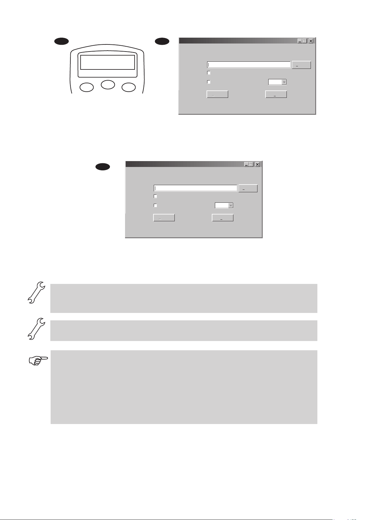
Run the SynScanFirmwareLoader software on your PC. Once the program is
launched, you should see a window as Fig.p. The "HC.Version" button
provides the version number of the hardware, firmware and database of your
hand control. It is for your reference only. You will not need it for the update.
1.
2.
3.
4.
Updating the SynScan
TM
AZ Hand Control
Fig.p
ESC
SETUP
ENTER
1
2
3
4
5
6
7
8
9
0
TOUR
UTILITY
RATE
M IC
NGC
PLANET
USER
OBJECT
ID
23
21
Fig.r
Fig.q
ESC
SETUP
ENTER
SynScan
Ver. 1.7
Update
Click "Browse" to select the SynScanVXXXXAZ.ssf file in the SynScan folder. Click
"Update" to start downloading the new firmware into your SynScan
TM
AZ hand control. You
will see the status of the update below the "Update" and "HC. Version" buttons (Fig.s).
5.
6.
Fig.s
When the download is complete, the status will show "Update Complete". The SynScan
TM
hand control is now updated to the newest firmware. Generally it takes about 30 seconds
to update the firmware. It may take longer if you are using an USB to Serial adapter
(USB-to-RS232 converter).
If the error message "Can not connect to a SynScan hand control" is shown, check the cable connection
and the PC link cable itself. Make sure it is all in good working condition. Close all applications that
may be occupying the RS-232 port and try again.
If you receive the error message "Firmware update failed…", reset the hand control by removing the
power plug and then re-connecting it. Repeat the update procedure.
By default, the data communication rate between SynScan
TM
hand control and the PC is set to be 115kbps.
The RS-232C port on some PCs may not support such high rate. If the update process fails after a few
tries, you can reduce the rate by pressing the "SETUP" key on the hand control after the power supply is
plugged in. This will reduce the data rate to 38.4 kbps (mid-rate)* or 9.6 kbps (low-rate). The LCD screen
will show the word "Mi" or "Lo" in the lower right hand corner to indicate that it is now in medium or
low communication rate. The steps for updating the firmware remain the same except that now it takes
longer to complete.
*Available in SynScan Bootloader version 1.6 or later.
SynScan Firmware Loader
SynScan Firmware Loader
Ver. 3.0
Firmware File:
Enforce database update
Auto-detect COM Port COM Port
Browse
HC. Version
Update
Update
COM 1
SynScan Firmware Loader
SynScan Firmware Loader
Ver. 3.0
Firmware File:
Enforce database update
Auto-detect COM Port COM Port
Browse
HC. Version
Update
Update
COM 1
78%
24
22
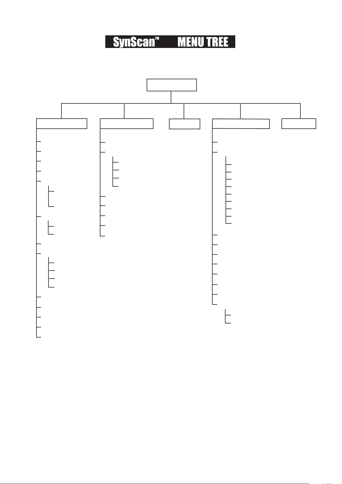
MAIN MENU
Date
Time
Observ. Site
Daylight Saving
Alignment
Alignment Stars
Backlash
Tracking
Auto-Tracking
Set Slew Limits
Re-align Encoder
Handset Setting
Factory Setting
Brightest Star
Align.
2-Star Align
SETUP MODE
Show Position
Show Information
Park Scope
PAE
Clear PAE Data
GPS
PC Direct Mode
Sidereal Rate
Lunar Rate
Solar Rate
Stop Tracking
Auto Select
Sort By
Time
Version
Temperature
Power Voltage
UTILITY FUNC. IDENTIFY
Named Star
Solar System
NGC Catalogue
IC Catalog
Messier Catalog
Caldwell Catalog
SAO Catalogue
Double Star
Variable Star
User Objects
Recall Object
Edit Object
Mercury
Venus
Mars
Jupiter
Saturn
Uranus
Neptune
Pluto
Moon
OBJECT CATALOG
TOUR
AZ

25
23
SynScan
TM
AZ SPECIFICATIONS
Power Supply:
Motor type:
Slew speeds:
10 to 15 V DC 1Amp, 2.1mm Plug (Center positive)
DC Servo Motors
Rate 0 = 1.0X
Rate 1 = 2.0X
Rate 2 = 8X
Rate 3 = 16X
Rate 4 = 32X
Rate 5 = 200X
Rate 6 = 400X
Rate 7 = 600X
Rate 8 = 800X
Rate 9 = 1000X
Sidereal, Lunar, Solar
Dual Axes Tracking
Brightest-Star Alignment, Two-Star Alignment
25 user defined objects. Complete M, NGC and IC catalog, partial
SAO catalogues, total 42,900 objects
Up to 5 arc min
Motor encoder: 1,620,000 counts per revolution,
Main axis encoder: 11,748 counts per revolution
Tracking Rates:
Tracking Mode:
Alignment Method:
Database:
Go-To Pointing Accuracy:
Resolution:

26
The SynScan
TM
AZ telescopes are designed to receive control commands sent from a computer
via the RS-232 port and RS-232 cable. Once connected, the SynScan
TM
AZ can be controlled by
most popular planetarium software program. The SynScan
TM
AZ will communicate with the
personal computer at 9600 bits/sec, no parity and stop bit. All angles are communicated with 16
bit angle and communicated using ASCII hexadecimal.
I
Description PC Command ASCII
Hand Control
Response
Notes
Echo Kx X#
Useful to check
communication
Goto Azm-Alt B12AB, 4000 # 10 characters sent.
B=Command, 12AB=Azm,
comma, 4000=Alt. If
command conflicts with slew
limits, there will be no action.
Goto Ra-Dec R34B, 12CE # Scope must be aligned. If
command conflicts with slew
limits, there will be no action.
Get Azm-Alt Z 12AB, 4000# 10 characters returned,
12AB=Azm, comma,
4000=Alt, #
Get RA-Dec E 34AB, 12CE# Scope must be aligned.
Cancel Goto M #
Is Goto in Progress L 0# or 1# 0=No, 1=Yes: “0” is ASCII
character zero
Is Alignment Complete J 0# or 1# 0=No, 1=Yes
HC version V 22 Two bytes representing V2.2
Stop/Start Tracking Tx
x= 0 (Tracking off)
x= 1 (Alt-Az on)
x= 2 (EQ-N)
x= 3 (EQ-S)
# Alt-Az tracking requires
alignment
32-bit goto RA-Dec r34AB0500,12CE0500 #
32-bit get RA-Dec e 34AB0500,
12CE0500#
The last two characters will
always be zero.
32-bit goto Azm-Alt b34AB0500,12CE0500 #
32-bit get Azm-Alt z 34AB0500,
12CE0500#
The last two characters will
always be zero.
27
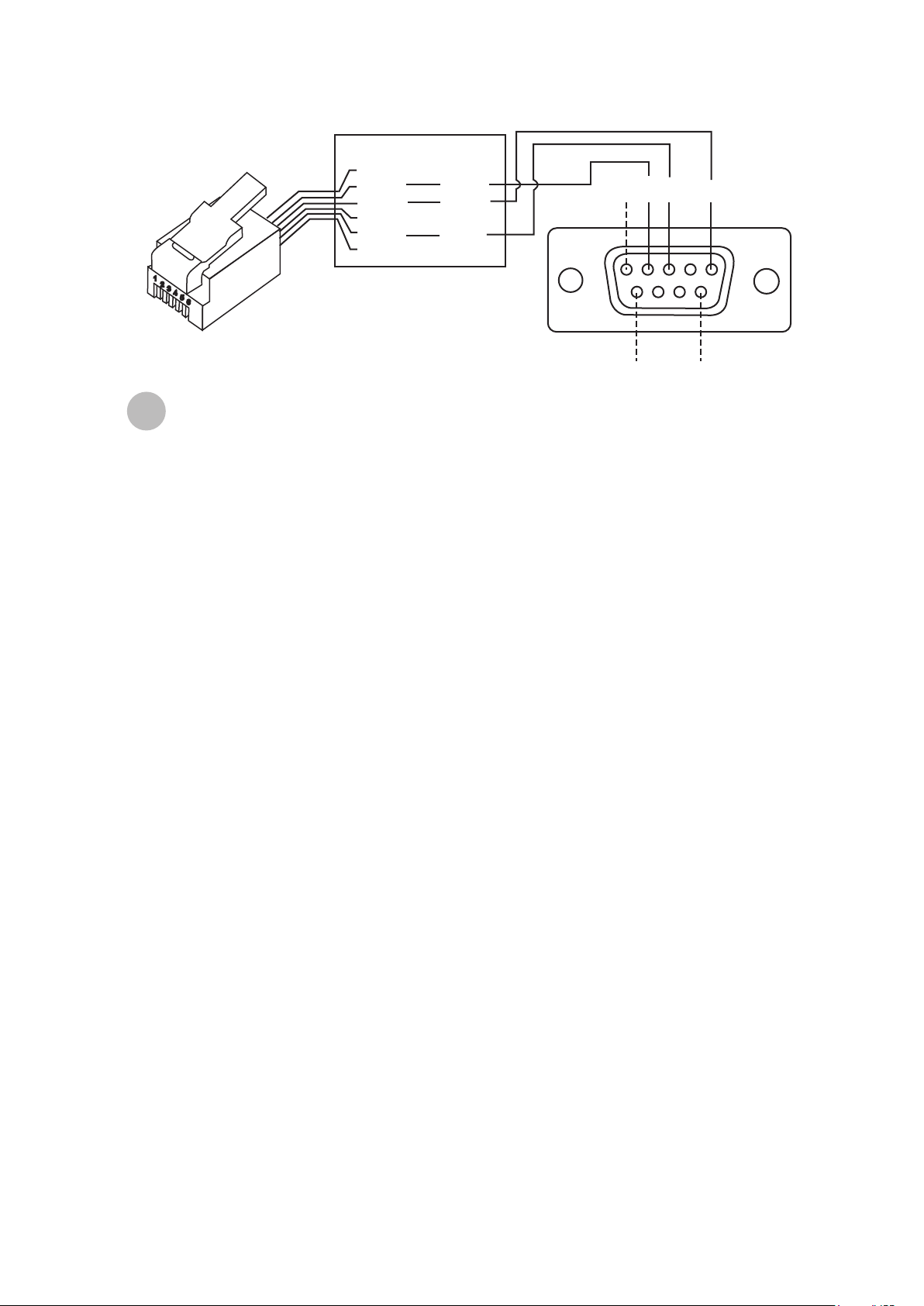
Physical Connection Diagram
II
1= NC
2= RD
3= GND
4= NC
5= TD
6= NC
RD = 2
GND = 5
TD = 3
1 2
6
The Back of the DB9 Pinout
RJ-11 Connector
9
3 5
1
2
3
4
5
6
Sending a track rate through RS232 to the hand control
Multiply the desired tracking rate (arc seconds /second) by 4. For example: if the
desired track rate is 120 arc seconds/second (proximately 8 times of sidereal rate),
then the TRACKRATE = 480.
Separate TRACKRATE into two bytes, such that (TRACKRATE =
TrackRateHighByte*256 + TrackRateLowByte). For example TRACKRATE = 480,
then TrackRateHighByte = 1, TrackRateLowByte = 224.
To send a tracking rate, send the following 8 bytes:
1.
2.
3.
Additional RS232 Commands
a. Positive Azm tracking: 80, 3, 16, 6, TrackRateHighByte, TrackRateLowByte, 0, 0
b. Negative Azm tracking: 80, 3, 16, 7, TrackRateHighByte, TrackRateLowByte, 0, 0
c. Positive Alt tracking: 80, 3, 17, 6, TrackRateHighByte, TrackRateLowByte, 0, 0
d. Negative Alt tracking: 80, 3, 17, 7, TrackRateHighByte, TrackRateLowByte, 0, 0
The number 35 is returned from the hand control.
4.
Sending a slow-Goto command through RS232 to the hand control
Convert the angle position to a 24bit number. Example: if the desired position is 220?,
then POSITION_24BIT = (220/360)*224 = 10,252,743
Separate POSITION_24BIT into three bytes such that (POSITION_24BIT =
PosHighByte * 65536 + PosMedByte * 256 + PosLowByte). Example: PosHighByte =
156, PosMedByte = 113, PosLowByte = 199
Send the following 8 bytes:
1.
2.
3.
a. Azm Slow Goto: 80, 4, 16, 23, PosHighByte, PosMedByte, PosLowByte, 0
b. Alt Slow Goto: 80, 4, 17, 23, PosHighByte, PosMedByte, PosLowByte, 0
The number 35 is returned from the hand control.
4.
Resetting the position of Az or Alt
Convert the angle position to a 24bit number, same as Slow-Goto example.\
Send the following 8 bytes:
1.
2.
3.
a. Azm Set Position: 80, 4, 16, 4, PosHighByte, PosMedByte, PosLowByte, 0
b. Alt Set Position: 80, 4, 17, 4, PosHighByte, PosMedByte, PosLowByte, 0
The number 35 is returned from the hand control.

28
III

NEVER USE YOUR TELESCOPE TO LOOK DIRECTLY AT THE SUN. PERMANENT EYE
DAMAGE WILL RESULT. USE A PROPER SOLAR FILTER FOR VIEWING THE SUN. WHEN
OBSERVING THE SUN, PLACE A DUST CAP OVER YOUR FINDERSCOPE TO PROTECT IT
FROM EXPOSURE. NEVER USE AN EYEPIECE-TYPE SOLAR FILTER AND NEVER USE
YOUR TELESCOPE TO PROJECT SUNLIGHT ONTO ANOTHER SURFACE, THE INTERNAL
HEAT BUILD-UP WILL DAMAGE THE TELESCOPE OPTICAL ELEMENTS.
Caution!