Owner's Manual
II:RRFTSMRNI
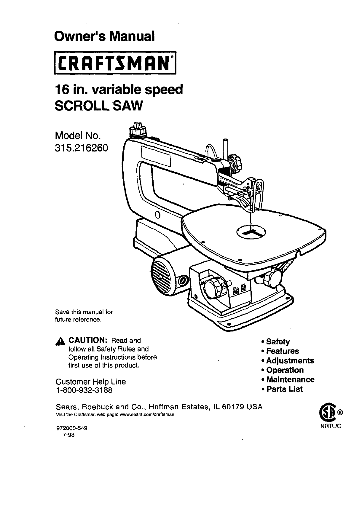
16 in, variable speed
SCROLL SAW
Model No.
315.216260
Save this manual for
future reference.
CAUTION: Read and
follow all Safety Rulesand
Operating Instructionsbefore
first use of thisproduct.
Customer Help Line
1-800-932-3188
• Safety
• Features
• Adjustments
• Operation
• Maintenance
• Parts List
Sears, Roebuck and Co., Hoffman Estates, IL 60179 USA
VisLtthe Craftsman web page: www.sears,com/craftsrnan
97200O-549
7-98
®
NRTL/C
• Table of Contents ........................................................................................................................................... 2
• Warranty and Introduction.............................................................................................................................. 2
• Rules For Safe Operation ......................................................................................................................... 3 - 5
• Electrical.......................................................................................................................................................... 6
• Glossary and ProductSpecifications ............................................................................................................. 7
• Unpacking and Tools Needed ........................................................................................................................ 8
• Labels ............................................................................................................................................................. 9
• Features .................................................................................................................................................. 10-11
• Assembly................................................................................................................................................. 11-12
• Adjustments............................................................................................................................................. 12-15
• Operation................................................................................................................................................. 16-19
• Maintenance ............................................................................................................................................ 19-20
• Troubleshooting............................................................................................................................................ 20
• Exploded View and Repair Parts List...................................................................................................... 22-25
f
• Parts Ordering / Service ............................................................................................................................... 26
FULL ONE YEAR WARRANTY ON CRAFTSMAN SCROLL SAW
If this rRRFTSMRN" Scroll Saw fails due to a defect in material or workmanship within one year from the date of
purchase, Sears willrepair it, free ofcharge.
Contact a Sears Service Center for repair.
If this product is used for commercial or rental purposes, thiswarranty applies only for 90 days from the date of
purchase.
This warranty gives you specific legal rights, and you may also have other rights whichvary from state to state.
Sears, Roebuck and Co., Dept. 817WA, Hoffman Estates, IL 60179
Yoursaw has many features for makingcutting
operations more pleasant and enjoyable. Safety,
performance and dependability have been given top
priorityin the design of this saw making iteasy to
maintain and operate.
_I, CAUTION: Carefully read throughthis entire
owner's manual before usingyour new saw. Pay
close attention to the Rules For Safe Operation,
and all Safety Alert Symbols includingDanger,
Warning and Caution. Ifyou use your saw
properly and onlyfor what it isintended, you will
enjoy years ofsafe, reliable service.
_. Look for this symbol to point out important safety precautions. It means attention!H Your
safety is involved.
_IL WARNING:
The operation of any power tool can resultin foreign objects being thrown intoyour eyes,
which can result in severe eye damage. Before beginning power tool operation, always wear
safety gogglesor safety glasses with side shields and a full face shield when needed. We
recommend Wide Vision Safety Mask for use over eyeglasses or standard safety glasses
with side shields, available at Sears Retail Stores.
2
ThepurposeofsafetysymbolsIs to attract your attention to possible dangers. The safety symbols, and
the explanations with them, deserve your careful attention and understanding. The safety warnings do
not by themselves eliminate any danger. The instructions or warnings they give are not substitutes for
proper accident prevention measures.
SYMBOL
A
A
MEANING
SAFETY ALERT SYMBOL:
Indicates danger, warning or caution.May be used in conjunctionwith other symbolsor picto-
graphs.
DANGER: Failure to obey a safety waming willresult in serious injury to yourself or to others.
Always follow the safety precautions to reduce the risk of fire, electric shock and personal injury.
,a,
WARNING: Failureto obey a safety warningcan resultin serious injuryto yourselfor to others.
Always follow the safety precautionsto reducethe riskof fire, electricshockand personalinjury.
&
Note:
CAUTION: Failureto obey a safety warning may resultin propertydamage or personal injuryto
yourself orto others. Alwaysfollow the safety precautionsto reduce the riskoffire, electricshock
and personal injury.
r
Advises you of information or instructionsvital tothe operation or maintenance of the equipment.
IMPORTANT
Servicing requires extreme care and knowledge of the system and shouldbe performed onlyby a qualified
service technician. For service we suggestyou return the toolto yournearest Sears store for repair. Always use
originalfactory replacement parts when servicing.
_lb WARNING: Do not attempt to operate this tool
untilyou have read thoroughly and understand
completely all instructions,safety rules, etc.
contained in this manual. Failure to complycan
result in accidents involvingfire, electric shock,
or serious personal injury. Save 6wner's manual
and review frequently for continuingsafe
operation, and instructingotherswho may use
this tool.
,_ WARNING: Do not connect your scrollsaw to a
power source untilyou have assembled and
adjusted the saw as described in this manual
and have read and understoodall precautions
and operating instructionsin the manual and
printed on the tool.
READ ALL INSTRUCTIONS
• KNOW YOUR POWER TOOL. Read the owner's
manual carefully. Learn the saw's applications
and limitationsas well as the specificpotential
hazards related to this tool.
• GUARD AGAINST ELECTRICAL SHOCK BY
PREVENTING BODY CONTACT WITH
GROUNDED SURFACES. For example; pipes,
radiators, ranges, refrigeratorenclosures.
• KEEP GUARDS IN PLACE and in good working
order.
• REMOVE ADJUSTING KEYS AND
WRENCHES. Get in the habit ofchecking to see
that hex keys and adjustingwrenches are
removed from tool beforeturning on the saw.
• KEEP THE WORK AREA CLEAN. Cluttered
work areas and work benches inviteaccidents.
DO NOT leave toolsor pieces of wood on the
saw while itis in operation.
• DO NOT USE IN DANGEROUS ENVIRON-
MENTS. Do not use power toolsnear gasoline or
other flammable liquids,in damp or wet loca-
tions, or expose them to rain. Keep the work
area well lit.
• KEEP CHILDREN AND VISITORS AWAY. All
visitorsshouldwear safety glasses and be kept s
safe distancefrom work area. Do not letvisitors
contact toolor extension cord whileoperating.
• MAKE WORKSHOP CHILD-PROOF with
padlocks and master switches or by removing
starter keys,
• DO NOT FORCE THE TOOL. Itwilldo thejob
better and safer at the rate for which itwas
designed.
• USE THE RIGHT TOOL. Do not force the toolor
attachment to do a job itwas not designed for.
Don't use itfor a purposenot intended,
3

RULES FOR SAFE OPERATION (Continued)
m
U_E THE PROPER EXTENSION CORD. Make
sure your extension cord is in good condition.
When usingan extension cord, be sure to use
one heavy enough to carry the current your
productwilldraw. An undersizedcord willcause
a drop in linevoltage resultingin'loss of power
and overheating. A wire gage size (A.W.G.) of at
least 18 is recommended for an extension cord
25 feet or less in length. If in doubt, use the next
heavier gage. The smaller the gage number, the
heavier the cord.
m
INSPECT EXTENSION CORDS PERIODI-
CALLY and replace if damaged.
DRESS PROPERLY. Do not wear looseclothing,
gloves, neckties, rings,bracelets, or other
jewelry. They can get caught and draw you into
moving parts. Rubber glovesand nonslip foot-
wear are recommended. Alsowear protective
hair coveringto contain long hair.
ALWAYS WEAR SAFETY GLASSES WITH
SIDE SHIELDS. Everyday eyeglasses have only
impact-resistant lenses; they are NOT safety
glasses.
PROTECT YOUR LUNGS. Wear a face or dust
mask ifthe cutting operation isdusty.
PROTECT YOUR HEARING. Wear hearing
protectionduring extended periods of operation.
SECURE WORK. Use clamps or a vise to hold
work when practical. It's safer than usingyour
hand and it frees both hands to operate tool.
• DO NOT OVERREACH. Keep proper footing and
balance at all times.
MAINTAIN TOOLS WITH CARE. Keep tools
sharp and clean for better and safer perfor-
mance. Followinstructionsfor lubricatingand
changing accessories.
DISCONNECT ALL TOOLS. When not in use,
before servicing,or when changingattachments,
blades, bits,cutters, etc., all toolsshould be
disconnected from power supply.
AVOID ACCIDENTAL STARTING. Be sure
switch is offwhen pluggingin.
USE RECOMMENDED ACCESSORIES. The
use of improper accessories may cause riskof
injury.
NEVER STAND ON TOOL. Serious injurycould
occurif the tool istipped or ifthe blade is unin-
tentionallycontacted.
CHECK DAMAGED PARTS. Before further use
of the tool, a guard or other part that isdamaged
should be carefully checked to determine that it
m
willoperate properly and perform itsintended
function. Check for alignment ofmoving parts,
bindingof movingparts, breakage of parts, saw
stability,mountingand any other conditionsthat
may affect itsoperation. A guard or other part
that isdamaged mustbe properly repaired or
replaced by a qualified service technicianat a
Sears store to avoid risk of personal injury.
DIRECTION OF FEED. Feed work intoa blade
or cutter againstthe direction of rotationofthe
blade or cutter only.
NEVER LEAVE TOOL RUNNING UNAT-
TENDED. TURN THE POWER OFF. Do not
leave tooluntil itcomes to a complete stop.
USE ONLY CORRECT BLADES. Use the right
blade size, style and cuttingspeed for the
material and the type of cut. Blade teeth should
pointdown toward the table. Sharp blades
minimize stallingand kickback. Correctly adjust
blade tension.
TO PROTECT THE OPERATOR and minimize
blade breakage, ALWAYS adjust the hold down
foot tojust clear the workpiece. Never operate
the saw with any guard or cover removed. Make
sure all guards are operating properly before
each use.
KEEP HANDS AWAY FROM CUTTING AREA.
Do not hand hold pieces so small that your
fingers go under the blade guard. Never reach
underneath work or behind, under, or within
three inches of the blade and itscutting path with
your hands and fingers for any reason. Do not
attemptto remove cutmaterial when blade is
moving.
,_k WARNING: Blades coast afterturn off.
• AVOID PINCHING THE BLADE. Be cautious
when cuttingoff material which is irregularin
cross section. Forexample, molding mustlay flat
on the table and not be permitted to rock.
• DO NOT ABUSE CORD. Never yank cord to
disconnect itfrom receptacle. Keep cord from
heat, oil, and sharp edges.
• INSPECT TOOL CORDS PERIODICALLY and if
damaged, have repaired by a qualified service
technicianat a Sears store. Stay constantly
aware of cord locationand keep itwell away
from the rotatingblade.
• DO NOT USE TOOL IF SWITCH DOES NOT
TURN IT ON AND OFF. Have defective switches
replaced bya qualified service technician at a
Sears store.

RULES FOR SAFE OPERATION (Continued)
KEEP TOOL DRY, CLEAN, AND FREE FROM
OIL AND GREASE. Always use a clean cloth
when cleaning. Never use brake fluids, gasoline,
petroleum-based products,or any solventsto
clean tool
A LARGE PIECE OF MATERIAL SHOULD BE
SUPPORTED while cutting.To minimize riskof
blade pinchingand kickback, always support
long workpieces. Saw may slip,walk or slide
while cutting long or heavy boards.
BEFORE MAKING A CUT, BE SURE ALL
ADJUSTMENTS ARE SECURE.
BEFORE CHANGING THE SETUP, REMOVING
COVERS, GUARDS OR BLADE, UNPLUG THE
SAW, AND REMOVE THE SWITCH KEY.
• DO NOT FEED THE MATERIAL TOO QUICKLY
while cutting. Do not force the workpiece against
the blade.
• NEVER CUT MORE THAN ONE WORKPIECE
AT A TIME. If making a stacked cut, all of the
pieces mustbe secured to each other with
masking tape or double sticktape to make one
workpiece. Do not put more than one workpiece
on the saw table at a time. Always hold the work
firmlyagainst the table. See page 18.
• AVOID CU'I-FING NAILS. Inspect for and
remove all nails from lumber before cutting.
• NEVER PERFORM LAYOUT, ASSEMBLY, OR
SETUP WORK ON THE TABLE while the
cutting tool isoperating.
• NEVER TOUCH BLADE or other moving parts
during use,
• NEVER START A TOOL WHEN THE BLADE IS
IN CONTACT WITH THE WORKPIECE. Clear
the table of debris before turning your scrollsaw
on,
ALLOW THE MOTOR TO COME UP TO FULL
SPEED before starting a cut.
FIRMLY CLAMP OR BOLT your scrollsaw to a
firm, level workbench or table. The most comfort-
able saw table height is at approximately hip
height.
• AVOID AWKWARD OPERATIONS A_D HAND
POSITIONS where a sudden slipcould cause
your hand to move intothe blade. ALWAYS
make sure you have good balance. Do not cut
pieces of material that are too small to hold
comfortablyin your hand.
• REPLACEMENT PARTS. All repairs, whether
electrical or mechanical, shouldbe made by
qualified service technician at a Sears store or
repair center.
_1= WARNING: When servicing use onlyidentical
Craftsman replacement parts. Use ofany other
parts may create a hazard or cause product
damage.
• NEVER USE IN AN EXPLOSIVE ATMO-
SPHERE. Normal sparkingof the motor could
ignitefumes.
• DO NOT OPERATE THIS TOOL WHILE UN-
DER THE INFLUENCE OF DRUGS, ALCOHOL,
OR ANY MEDICATION.
STAY ALERT AND EXERCISE CONTROL.
Watch what you are doingand use common
sense. Do not operate tool when you are tired.
Do not rush.
• MAKE SURE THE WORK AREA HAS AMPLE
LIGHTING tosee the work and that no obstruc-
tionswill interfere with safe operation BEFORE
performingany work using yoursaw.
• ALWAYS TURN OFF SAW before disconnecting
it, to avoidaccidental starting when reconnecting
to powersupply. NEVER leave the scrollsaw
unattendedwhile connected to a power source.
_. WARNING: Do not allow familiaritywith your
saw make you careless. Remember that a
careless fractionof a second is sufficientto inflict
severe injury.
SAVE THESE INSTRUCTIONS. Refer tothem
frequentlyand use to instructother users. If you
loan someone thistool, loan them these instruc-
tions also.
SAVE THESE INSTRUCTIONS
5
EXTENSION CORDS
Use only 3-wire extension cords that have 3-prong
grounding plugs and 3-pole receptacles that accept
the tool's plug. When using a power tool at a consider-
able distance from the power source, use an exten-
sion cord heavy enough to carry the current that the
tool will draw. An undersized extension cord will
cause a drop in line voltage, resulting in a loss of
power and causing the motor to overheat. Use the
chart provided below to determine the minimum wire
size required in an extension cord. Only round jack-
eted cords listed by Underwriter's Laboratories (UL)
should be used.
Length of Extension Cord
Up to 25 feet
Wire Size (A.W.G.)
18
26-100 feet 16
When working with the tool outdoors, use an exten-
sion cord that is designed for outside use. This is
indicated bythe letters WA on the cord's jacket.
Before using an extension cord, inspect it for loose or
exposed wires and cut or worn insulation.
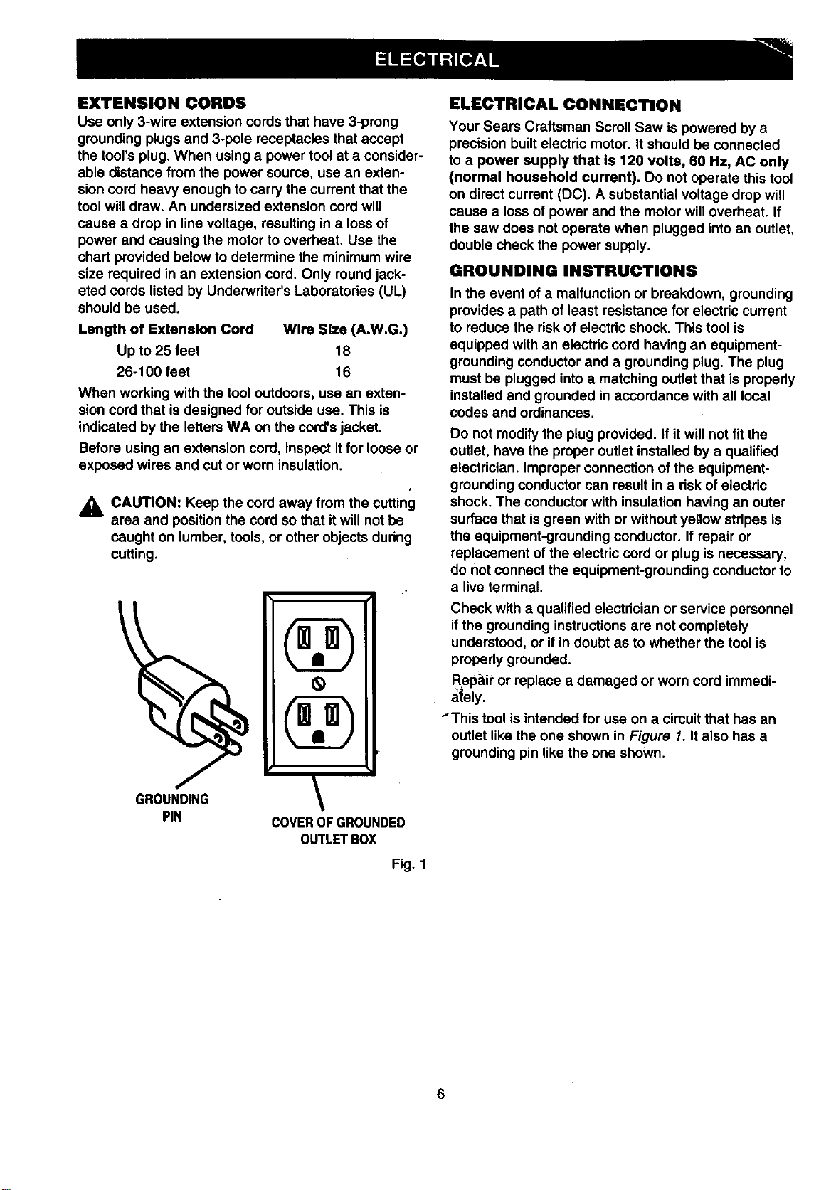
_i, CAUTION: Keep the cord away from the cutting
area and position the cord so that it will not be
caught on lumber, tools, or other objects during
cutting.
GROUNDING
PIN COVEROFGROUNDED
OUTLETBOX
Fig. 1
ELECTRICAL CONNECTION
Your Sears Craftsman Scroll Saw is powered by a
precision built electric motor. It should be connected
to a power supply that Is 120 volts, 60 Hz, AC only
(normal household current). Do not operate this tool
on direct current (DC). A substantial voltage drop will
cause a loss of power and the motor will overheat. If
the saw does not operate when plugged into an outlet,
double check the power supply.
GROUNDING INSTRUCTIONS
In the event of a malfunction or breakdown, grounding
provides a path of least resistance for electric current
to reduce the risk of electric shock. This tool is
equipped with an electric cord having an equipment-
grounding conductor and a grounding plug. The plug
must be plugged into a matching outlet that is propedy
installed and grounded in accordance with all local
codes and ordinances.
Do not modify the plug provided. If itwill not fit the
outlet, have the proper outlet installed by a qualified
electrician. Improper connection of the equipment-
grounding conductor can result in a risk of electric
shock. The conductor with insulation having an outer
surface that is green with or without yellow stripes is
the equipment-grounding conductor. If repair or
replacement of the electric cord or plug is necessary,
do not connect the equipment-grounding conductor to
a live terminal.
Check with a qualified electrician or service personnel
if the grounding instructions are not completely
understood, or if in doubt as to whether the tool is
properly grounded.
Repair"or replace a damaged or worn cord immedi-
ately.
"This tool is intended for use on a circuit that has an
outlet like the one shown in Figure 1. It also has a
grounding pin like the one shown.
6

Bevel Cut
A cutting operation made with the table at any angle
other than 90" to the blade.
Crosscut
A cutting or shaping operation made across the grain
of the workpiece.
Compound Cut
A compound cut is a cut made using a miter angle
and a bevel angle at the same time.
Freehand (for scroll saw)
Performing a cut without the workpiece properly
supported on the table.
Gum
A sticky, sap based residue from wood products.
Kerr
The matedal removed by the blade in a through cut or
the slot produced by the blade in a nonthrough or
partial cut.
Leading End
The end of the workpiece pushed intothe cutting tool
fimt.
Miter Cut
A cutting operation made with the saw table at an_
angle other than 90" to the blade.
Nonferrous Metal
Metal that does not contain iron; such as aluminum,
brass, and copper.
Push Stick
A device used to feed the workpiece through the saw
blade during narrow rippingtype operations and helps
keep the operator's hands well away from the blade.
Resaw
A cutting operation to reduce the thickness of the
workpiece to make thinner pieces.
Resin
A sticky, sap base substance that has hardened.
Ripping
A cutting operation along the length of the workpiece.
Saw Blade Path
The area directly in line -- over, under, behind, or in
front of the blade. AS it applies to the workpiece, that
area which will be, or has been, cut by the blade.
Set
The distance that the tip of the saw blade tooth is bent
(or set) outward from the face of the blade.
SPM
Strokes per minute. Used in reference to blade
movement.
Throw-Back
Throwing of a workpiece in a manner similar to a
kickback. Usually associated with a cause other than
the kerr closing, such as a workpiece not being
against the fence, being dropped intothe blade, or
being placed inadvertently in contact with the blade.
Through Sawing
Any cutting operation where the blade extends
completely through the thickness of the workpiece.
Workpiece
The item on which the cutting operation is being done.
The surfaces of a workpiece are commonly referred to
as faces, ends, and edges.
Worktable
The surface on which the workpiece rests while
performing a cutting or sanding operation.
Throat
Motor
Drive
Blade Length
Table Size
16 in.
120 V, 1.2 amp 60 HZ-AC only
Variable Speed
500-1700 Strokes per minute
5 in. plain or pin
10-1/4 in. x 12 in.
Table Tilt
Overall Dimensions
Net Weight
47" right and 12" left
12in. W
24-1/2 in. L
14in. H
27.5 lb.
7
,_ WARNING: To prevent accidental startingor
electrical shock that could cause possible
serious personal injury,assemble all parts to
your saw before connecting itto power supply.
Saw should never be connected to power supply
when you are assembling parts, making
adjustments, lubricating,installingor removing
blades, cleaning, or when not in use.
Carefully lift saw from the carton and place it on
a level work surface.
Remove pack of 4 extra blades and owner's
manual from the carton.
_, WARNING: If any parts are missing, do not
operate this tool untilthe missing parts are
replaced. Failure to do socould resultin possible
serious personal injury.
• Do not discardthe packing materials until you
have carefully inspected the saw, identifiedall
pads, and satisfactorilyoperated yournew saw.
Note: If any parts are damaged or missing,do not
attempt to plug in the powercord and turnthe switch
on untilthe damaged or missingparts are obtained
and are installedcorrectly.
Your scroll saw comes completely assembled. A
package of 4 extra blades and an owner's manual are
includedwith your saw.
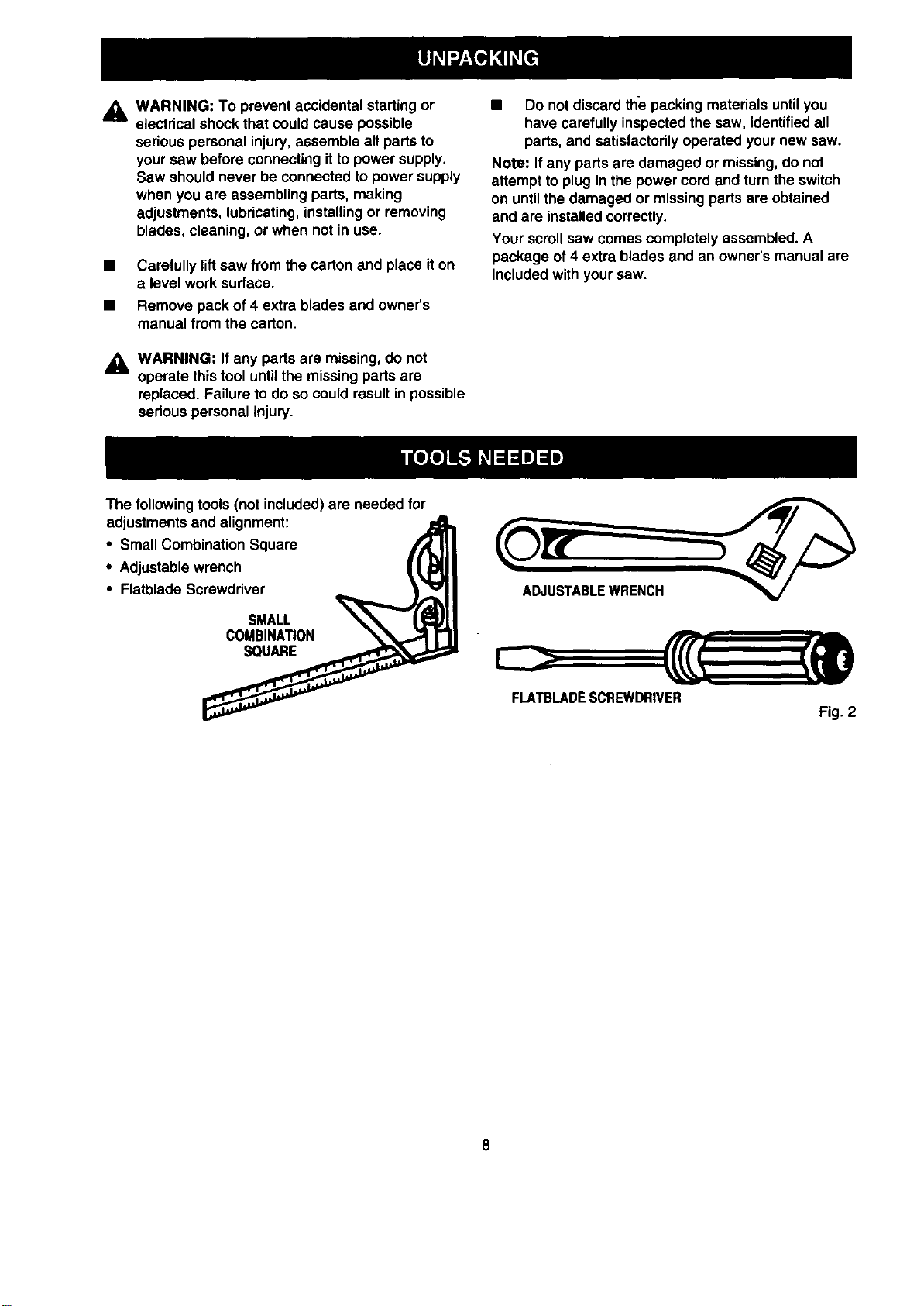
The following tools (not included) are needed for
adjustments and alignment:
• Small Combination Square
• Adjustablewrench
• Flatblade Screwdriver
SMALL
COMBINA_ON
SQUARE
FLATBLADESCREWDRIVER
Fig. 2
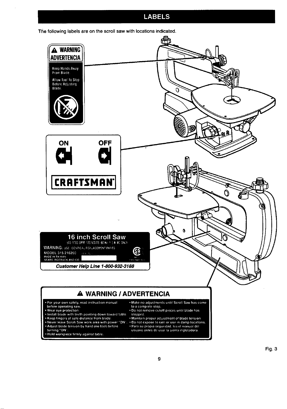
The following labels are on the scrollsaw with locations indicated.
WARNING
ADVERTENCIA
ON OFF
II:RRFTSMAN1
Customer Help Line 1-800-932-3188
WARNING I ADVERTENCIA
Fig. 3
Thisversatilevariablespeedscrollsawisgreatfor
makingtoys, puzzles, games, artwork, and jewelry. It
isa handy do-it-yourself tool. It cutswood, wood
compositionproducts, plastic, and other fibrous
material up to 2 inchesthick. It also cuts nonferrous
metals (aluminum, brass, copper).
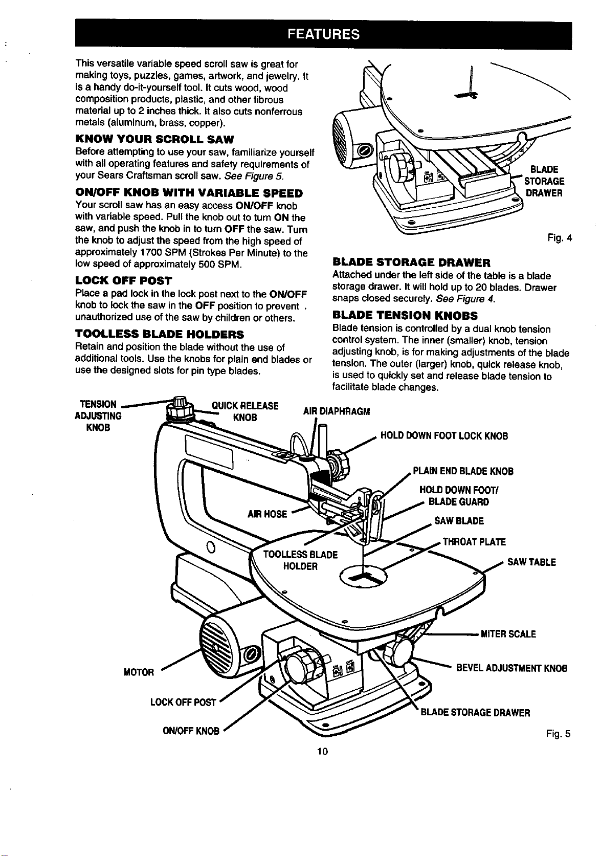
KNOW YOUR SCROLL SAW
Before attempting to use your saw, familiarize yourself
with all operating features and safety requirements of
your Sears Craftsman scrollsaw. See Figure 5.
ON/OFF KNOB WITH VARIABLE SPEED
Your scroll saw has an easy access ON/OFF knob
with variable speed. Pullthe knobout to turn ON the
saw, and pushthe knob in to turnOFF the saw. Turn
the knobto adjust the speed from the high speed of
approximately 1700 SPM (Strokes Per Minute) to the
low speed of approximately 500 SPM.
LOCK OFF POST
Place a pad lock in the lock post next tothe ON/OFF
knob to lookthe saw in the OFF positionto prevent ,
unauthorized use of the saw bychildren or others.
TOOLLESS BLADE HOLDERS
Retain and positionthe bladewithout the use of
additionaltools. Use the knobsfor plain end blades or
use the designed slotsfor pintype blades.
TENSION QUICKRELEASE
ADJUSTING KNOB
KNOB
BLADE
DRAWER
Fig. 4
BLADE STORAGE DRAWER
Attached under the leftside of the table is a blade
storage drawer. Itwill hold up to 20 blades. Drawer
snaps closed securely. See Figure 4.
BLADE TENSION KNOBS
Blade tension iscontrolledby a dual knob tension
controlsystem. The inner (smaller) knob, tension
adjusting knob, isfor making adjustments ofthe blade
tension. The outer (larger) knob, quick release knob,
is used to quicklyset and release blade tension to
facilitate blade changes,
AIRDIAPHRAGM
HOLDDOWNFOOTLOCKKNOB
PLAINENDBLADEKNOB
HOLDDOWNFOOT/
GUARD
SAWBLADE
SAWTABLE
MITERSCALE
MOTOR
BEVELADJUSTMENTKNOB
LOCKOFFPOS'I'
ON/OFFKNOB
10
Fig. 5
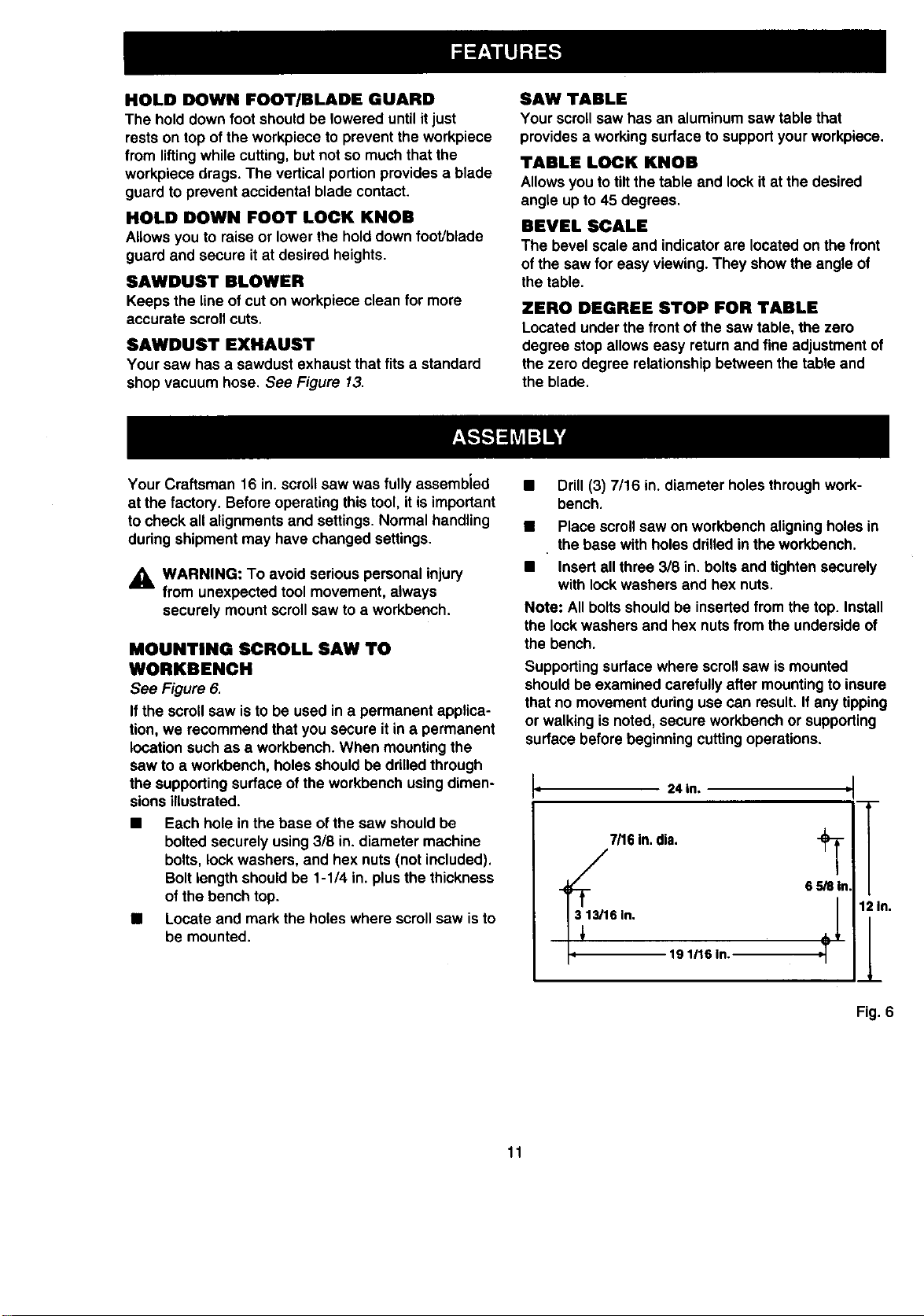
HOLD DOWN FOOT/BLADE GUARD
The hold down foot should be lowered until it just
rests on top of the workpiece to prevent the workpiece
from lifting while cutting, but not so much that the
workpiece drags. The vertical portion provides a blade
guard to prevent accidental blade contact.
HOLD DOWN FOOT LOCK KNOB
Allows you to raise or lower the hold down foot/blade
guard and secure itat desired heights•
SAWDUST BLOWER
Keeps the line ofcut on workpiece clean for more
accurate scroll cuts.
SAWDUST EXHAUST
Your saw has a sawdust exhaust that fits a standard
shopvacuum hose. See Figure 13.
SAW TABLE
Your scrollsaw has an aluminum saw table that
provides a workingsurface to supportyour workpiece.
TABLE LOCK KNOB
Allowsyou totilt the table and lock itat the desired
angle up to45 degrees.
BEVEL SCALE
The bevel scale and indicator are locatedon the front
of the saw for easy viewing. They show the angle of
the table•
ZERO DEGREE STOP FOR TABLE
Located under the front of the saw table, the zero
degree stopallows easy returnand fine adjustment of
the zero degree relationshipbetween the table and
the blade.
Your Craftsman 16 in.scroll saw was fully assembled
at the factory. Beforeoperating thistool, itis important
to check all alignments and settings. Normal handling
during shipment may have changed settings.
_L WARNING: To avoid serious personal injury
from unexpected tool movement, always
securely mountscroll saw to a workbench.
MOUNTING SCROLL SAW TO
WORKBENCH
See Figure 6.
If the scroll saw isto be used in a permanent applica-
tion, we recommend that you secure it in a permanent
location such as a workbench. When mountingthe
saw to a workbench, holes shouldbe drilledthrough
the supportingsurface ofthe workbench usingdimen-
sions illustrated.
• Each hole inthe base ofthe saw shouldbe
bolted securely using 3/8 in. diameter machine
bolts, lock washers, and hex nuts (not included).
Boltlength shouldbe 1-1/4 in. plus the thickness
ofthe bench top.
• Locate and mark the holes where scrollsaw is to
be mounted.
• Drill(3)7/16in. diameterholesthrough work-
bench.
Place scrollsaw on workbenchaligningholes in
the base with holes drilled in the workbench.
Insertall three 3/8 in. bolts and tighten securely
with lock washers and hex nuts.
Note: Allboltsshould be inserted from the top. Install
the lockwashers and hex nutsfrom the underside of
the bench.
Supporting surface where scrollsaw is mounted
shouldbe examined carefully after mountingto insure
that no movement during use can result. If any tipping
or walking is noted, secure workbench or supporting
surface before beginning cutting operations.
II
24 in.
7/16In.dia.
€ T'
6In.
19 1116 In.
.I
12 In.
Fig. 6
11

CLAMPING SCROLLSAW TO
WORKBENCH
See Figure 7.
tfthe scrollsaw isto be used in a portable application,
we recommend that you fasten itpermanently to a
mounting beard that can easily be clamped to a
workbenchor other supportingsurface. The mounting
board should be of sufficientsize to avoid tippingof
saw while in use.
Mount saw to board using holes in frame as a
template for hole pattern or the diagram in
Figure 6. Locate and mark the holeswhere scroll
saw isto be mounted.
• Follow lastthree steps in previoussection called
• ounUng Scroll Saw to Workbench.
Make sure mounting boltsare longenough togo
through holes in the saw frame, material being
mounted to, lock washers, and hex nuts.
Note: Itmay be necessary to countersink hex nuts
and washers on bettom side of mounting board.
\
C-CLAMP
C-CLAMP
WORKBENCH
MOUNTING
BOARD
Fig. 7
,_k WARNING: To preventaccidental startingthat
could cause possibleserious personal injury,
turn off the sew and unplug before making any
adjustments.
HOLD DOWN FOOT/BLADE GUARD
See Figure 8.
The hold down shouldbe adjusted so itcontactsthe
top surface of the work being cut. Tighten adjusting
knobafter adjustment has been made.
• Loosen the hold down foot lock knob.
• Move the hold down foot to the desired position.
• Tighten the hold downfoot lock knob.
The tall, front part of the hold down foot acts as a
blade guard to prevent accidental contact withthe
blade.
SAWDUST BLOWER
See Figure 8.
The dust blower isdesigned and preset to direct air to
the mosteffective point on the cutting line. Be sure
holddown foot isproperly adjusted to properly secure
workpiece and to properlydirect air to the cutting
surface.
• Inserthose to air diaphragm before startingthe
saw.
AIRDIAPHRAGM
HOLDDOWNFOOT
KNOB
BLADE
Fig. 8
12
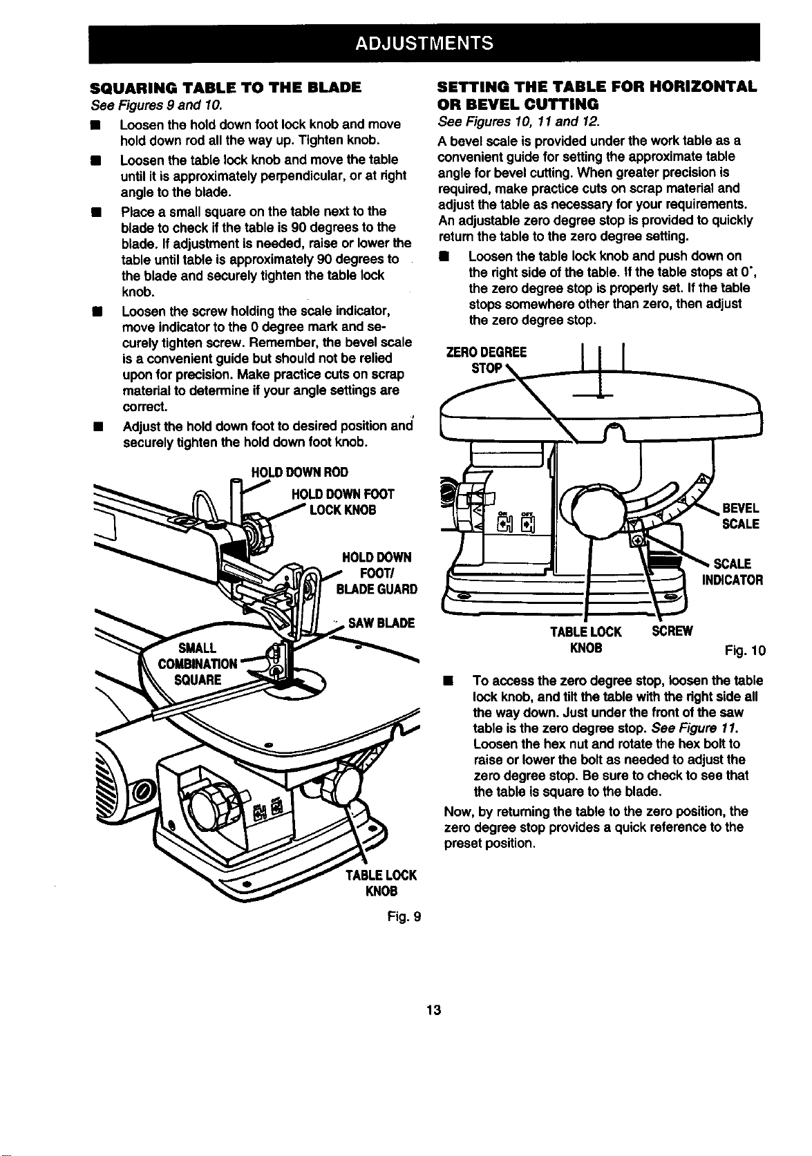
SQUARING TABLE TO THE BLADE
See Figures 9 and 10.
• Loosen the hold down foot lock knoband move
hold down rod all the way up. Tighten knob.
• Loosen the table lock knoband movethe table
until itis approximately perpendicular, or st right
angle to the blade.
• Place a small square on the table next to the
blade tocheck ifthe table is90 degrees tothe
blade. If adjustment isneeded, raise or lower the
table until table is approximately 90 degrees to
the blade and securely tighten the table lock
knob.
• Loosen the screw holdingthe scale indicator,
move indicatorto the 0 degree mark and se-
curely tighten screw. Remember, the bevel scale
is a convenient guide but shouldnot be relied
upon for precision. Make practice cutson scrap
material to determine ifyour angle settings are
correct.
i
• Adjust the hold downfoot to desired positionand
securely tightenthe hold down foot knob.
HOLDDOWNROD
HOLDDOWNFOOT
LOCKKNOB
HOLDDOWN
F00T/
. SAWBLADE
\
TABLELOCK
KNOB
Fig. 9
SETTING THE TABLE FOR HORIZONTAL
OR BEVEL CUTTING
See Figures 10, 11 and 12.
A bevel scale is providedunder the work table as a
convenient guide for settingthe approximate table
angle for bevel cutting.When greater precision is
required, make practice cuts on scrap material and
adjustthe table as necessary for your requirements.
An adjustable zero degree stop isprovided to quickly
return the table to the zero degree setting.
• Loosen the table lock knoband pushdown on
the rightside ofthe table. Ifthe table stopsat O',
the zero degree stop isproperly set. Ifthe table
stops somewhere other than zero, then adjust
the zero degree stop.
ZERODEGREE II I
"__ SCALE
TABLELOCK SCREW
KNOB Fig. 10
• To access the zero degree stop, loosen the table
lookknob, and tilt the table with the dghtside all
the way down. Just under the front ofthe saw
table is the zero degree stop. See Figure 11.
Loosen the hex nut and rotate the hex boltto
raise or lowerthe boltas needed to adjust the
zero degree stop. Be sure to check to see that
the table is square to the blade.
Now, by returningthe table to the zero position, the
zero degree stop provides a quick reference tothe
preset position.
13
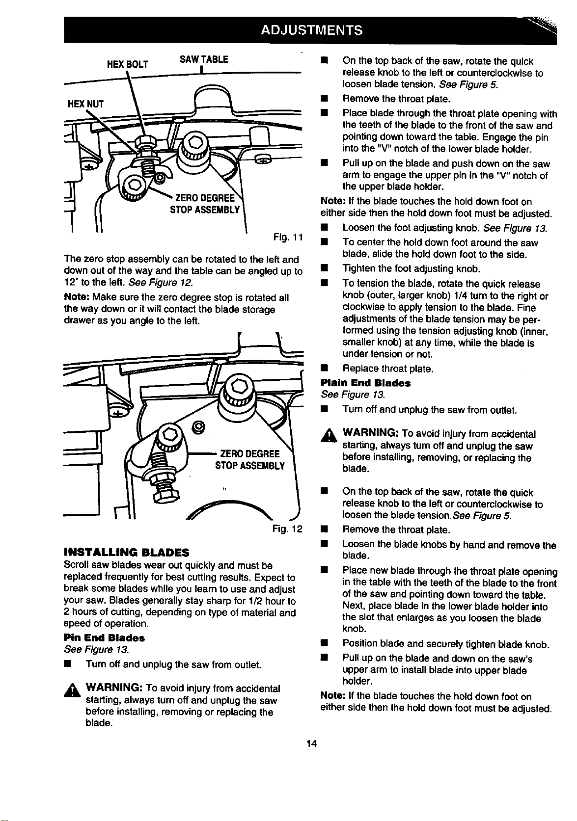
HEXBOLT SAWTABLE
HEXNUT
ZERODEGREE
STOPASSEMBLY
Fig.11
The zero stop assembly can be rotated to the left and
down out of the way and the table can be angled up to
12"to the left. See Figure 12.
Note: Make sure the zero degree stop is rotated all
the way down or itwill contact the blade storage
drawer as you angle to the left.
Fig. 12
INSTALLING BLADES
Scroll saw blades wear out quickly and must be
replaced frequently for best cutting results. Expect to
break some blades while you learn to use and adjust
your saw. Blades generally stay sharp for 1/2 hour to
2 hours of cutting, depending on type of material and
speed of operation.
Pin End Blades
See Figure 13.
• Turn off and unplug the saw from outlet.
,_ WARNING: To avoid injury from accidental
starting, always turn off and unplug the saw
before installing, removing or replacing the
blade.
• On the top back of the saw, rotate the quick
release knob to the left or counterclockwise to
loosen blade tension. See Figure 5.
• Remove the throat plate.
• Place blade through the throat plate opening with
the teeth of the blade to the front of the saw and
pointing down toward the table. Engage the pin
intothe "V"notch of the lower blade holder.
• Pull up on the blade and push down on the saw
arm to engage the upper pin in the "V" notch of
the upper blade holder.
Note: If the blade touches the hold down foot on
either side then the hold down foot must be adjusted.
• Loosen the foot adjusting knob. See Figure 13.
• To center the hold down foot around the saw
blade, slide the hold down foot to the side.
• Tighten the foot adjusting knob.
• To tension the blade, rotate the quick release
knob (outer, larger knob) 114turn to the right or
clockwise to apply tension to the blade. Fine
adjustments of the blade tension may be per-
formed using the tension adjusting knob (inner,
smaller knob) at any time, while the blade is
under tension or not.
• Replace throat plate.
Plain End •lades
See Figure 13.
• Turn off and unplug the saw from outlet.
A
WARNING: To avoid injuryfrom accidental
starting, always turn off and unplug the saw
before installing, removing, or replacing the
blade.
• On the top back of the saw, rotate the quick
release knob to the left or counterclockwise to
loosen the blade tension.See Figure 5.
• Remove the throat plate.
• Loosen the blade knobs by hand and remove the
blade.
Place new blade through the throat plate opening
in the table with the teeth of the blade to the front
of the saw and pointing down toward the table.
Next, place blade in the lower blade holder into
the slot that enlarges as you loosen the blade
knob.
Position blade and securely tighten blade knob.
Pull up on the blade and down on the saw's
upper arm to install blade into upper blade
holder.
Note: If the blade touches the hold down foot on
either side then the hold down foot must be adjusted.
14
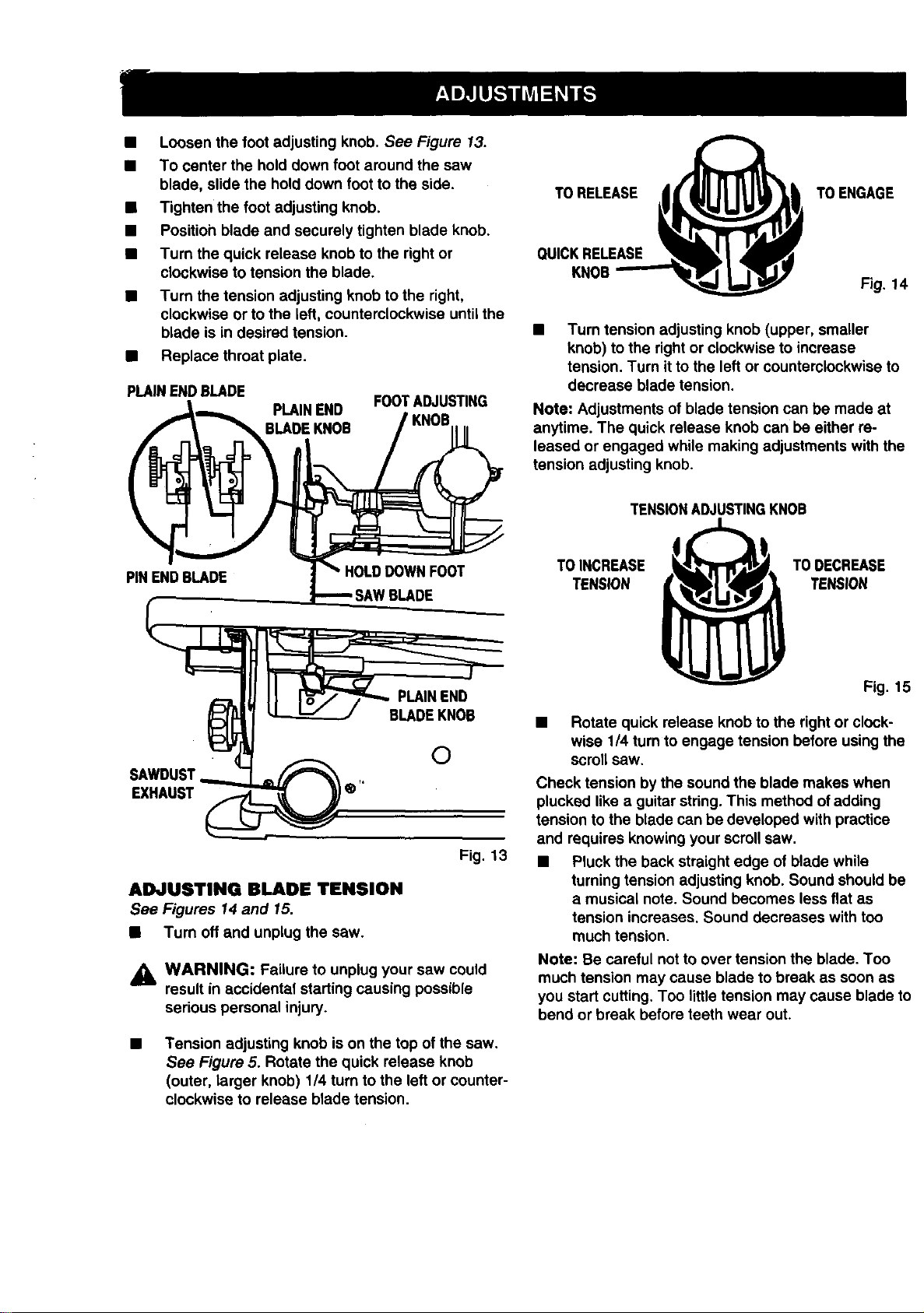
• Loosen the foot adjusting knob. See Figure 13.
• To center the hold down foot around the saw
blade, slide the hold down foot to the side.
• Tighten the foot adjusting knob.
• Position blade and securely tighten blade knob.
• Turn the quick release knob to the right or
clockwise to tension the blade.
• Turn the tension adjusting knob to the right,
clockwise or to the left, counterclockwise untilthe
blade is in desired tension.
• Replace throat plate.
PLAINENDBLADE
PLAINEND FOOTADJUSTING
BLADEKNOB
TORELEASE
QUICKRELEASE
KNOB
TOENGAGE
Fig. 14
Turn tension adjusting knob (upper, smaller
knob) to the right or clockwise to increase
tension. Turn it to the left or counterclockwise to
decrease blade tension.
Note: Adjustments of blade tension can be made at
anytime. The quick release knob can be either re-
leased or engaged while making adjustments with the
tension adjusting knob.
TENSIONADJUSTINGKNOB
PINENDBLADE
HOLDDOWNFOOT
TOINCREASE
TENSION
TODECREASE
TENSION
SAWDUST
EXHAUST
PLAINEND
BLADEKNOB
©
Fig. 13
ADJUSTING BLADE TENSION
See Figures 14 and 15.
• Turn off and unplug the saw.
,_k WARNING: Failure to unplug your saw could
result in accidental starting causing possible
serious personal injury.
Tension adjusting knob is on the top of the saw.
See Figure 5. Rotate the quick release knob
(outer, larger knob) 1/4 turn to the left or counter-
clockwise to release blade tension.
Fig. 15
• Rotate quick release knob to the right or clock-
wise 1/4 turn to engage tension before using the
scroll saw.
Check tension by the sound the blade makes when
plucked like a guitar string. This method of adding
tension to the blade can be developed with practice
and requires knowing your scroll saw.
• Pluck the back straight edge of blade while
turning tension adjusting knob. Sound should be
a musical note. Sound becomes less flat as
tension increases. Sound decreases with too
much tension.
Note: Be careful not to over tension the blade. Too
much tension may cause blade to break as soon as
you start cutting. Too little tension may cause blade to
bend or break before teeth wear out.
Thisscrollsawisdesignedtocutwood,woodcompo-
sitionproducts,plastic,andnonferrousmetals(alumi-
num,brass,copper).
GENERAL OPERATION
Please read and understand the following items
concerning yourscroll sew before attempting to use
the sew.
• There isa learning curve for each person who
wants to use this sew. Dudngthat pedod of time
itis expected that some blades will break until
you learn how to use and adjust the sew.
• Allow the saw to cutmaterial by guidingthe
workpiece into the blade as itmoves. Do not
force the work.
• The blade teeth cut matedal only on the down
stroke.
You mustguide the workpiece intothe blade
slowlybecause the teeth of the blade are very
small and can only remove matedal on the down
stroke.
• Scroll saw blades wear out and must be replaced
frequently for best cutting results.Scroll saw
blades generally stay sharp for 112hour to 2
hours ofcutting, depending on type of material
and speed ofoperation.
• To get accurate cuts, be prepared to compen-
sate for the blade's tendency to follow the wood
grain as you are cuttingwood.
• In cutting wood, best resultsare achieved when
cuttingwood lessthan one inchthick.
• When cuttingwood thicker than one inch, the
user mustguide the workpiece very slowlyinto
the blade and take extra care not to bend or twist
the blade while cutting.
• When choosing a blade to use with your scroll
sew, considerthe following carefully:
• Very fine, narrow blades shouldbe used to
scroll cut in thin matedal 1/4 in. thick or less.
Most blade packages state the size or thick-
ness and type of material whichthat blade is
intendedto cut. Package should also state the
radius, or size of curve, which can be cutwith
that blade.
• Wider blades cannot cutcurves as tightor
small as thinner blades.
• Blades wear faster:
• When cutting plywoodand other laminates.
• When cutting matedal thickerthan 3/4 in.
• When cutting hardwood.
• When side pressure isapplied to the blade.
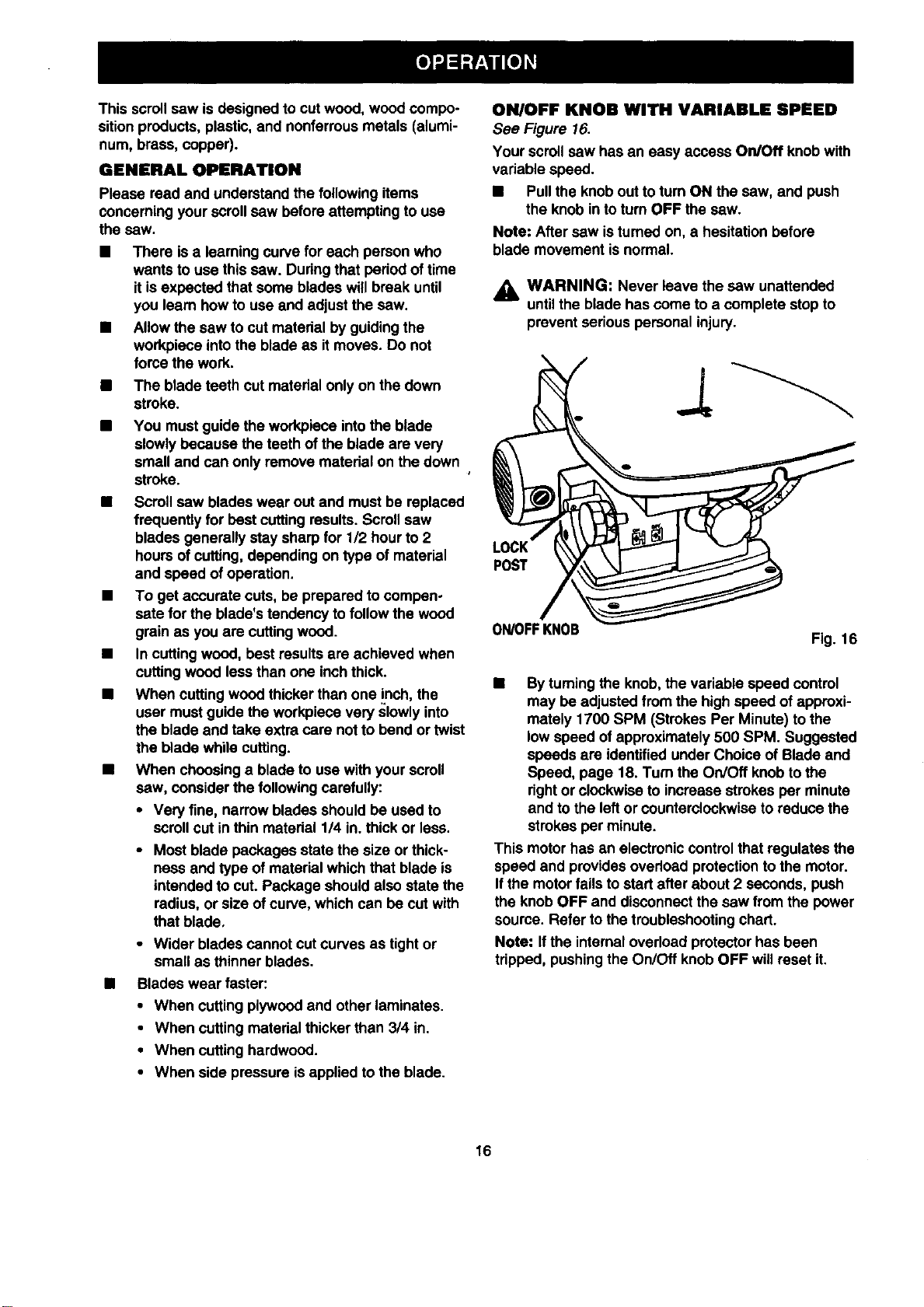
ON/OFF KNOB WITH VARIABLE SPEED
See Figure 16.
Your scroll saw has an easy access On/Off knobwith
variable speed.
• Pull the knob outto turn ON the saw, and push
the knob in toturn OFF the sew.
Note: After saw is turned on, a hesitation before
blade movement is normal.
WARNING: Never leave the saw unattended
untilthe blade has come to a complete stop to
prevent seriouspersonal injury.
POST
ON/OFFKNOB
Fig. 16
• Byturning the knob, the variable speed control
may be adjusted from the highspeed ofapproxi-
mately 1700 SPM (Strokes Per Minute) to the
low speed of approximately 500 SPM. Suggested
speeds are identified under Choice of Blade and
Speed, page 18. Turn the On/Off knobto the
rightor clockwise to increase strokes per minute
and to the left or counterclockwiseto reduce the
strokes per minute.
This motorhas an electroniccontrolthat regulates the
speed and providesovedoad protectionto the motor.
If the motor fails to start after about 2 seconds, push
the knob OFF and disconnectthe saw from the power
source. Refer tothe troubleshootingchart.
Note: I1the internaloverload protectorhas been
tripped, pushing the On/Off knobOFF will reset it.
16
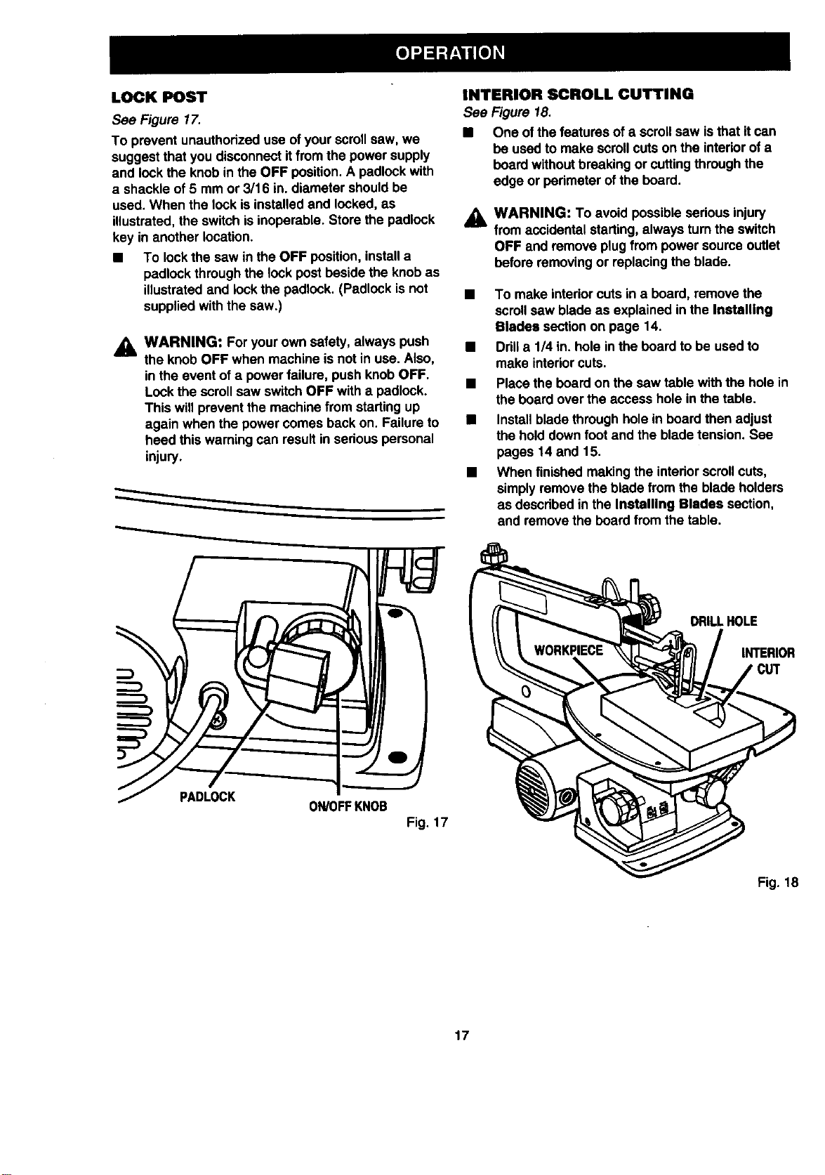
LOCK POST
See Figure 17.
To prevent unauthorizeduse ofyour scroll saw, we
suggest that you disconnectitfrom the power supply
and lockthe knob in the OFF position.A padlock with
a shackle of 5 mm or 3/16 in.diameter shouldbe
used. When the lock is installedand locked, as
illustrated,the switchis inoperable. Store the padlock
key in another location.
• To lock the saw in the OFF position, installa
padlock through the lock post beside the knob as
illustrated and lockthe padlock. (Padlock is not
supplied with the saw.)
,_ WARNING: Foryour own safety, always push
the knob OFF when machine is not in use. Also,
in the event of a power failure, push knob OFF.
Lock the scroll saw switch OFF with a padlock.
This will prevent the machine from starting up
again when the power comes back on. Failure to
heed this warning can resultin serious personal
injury.
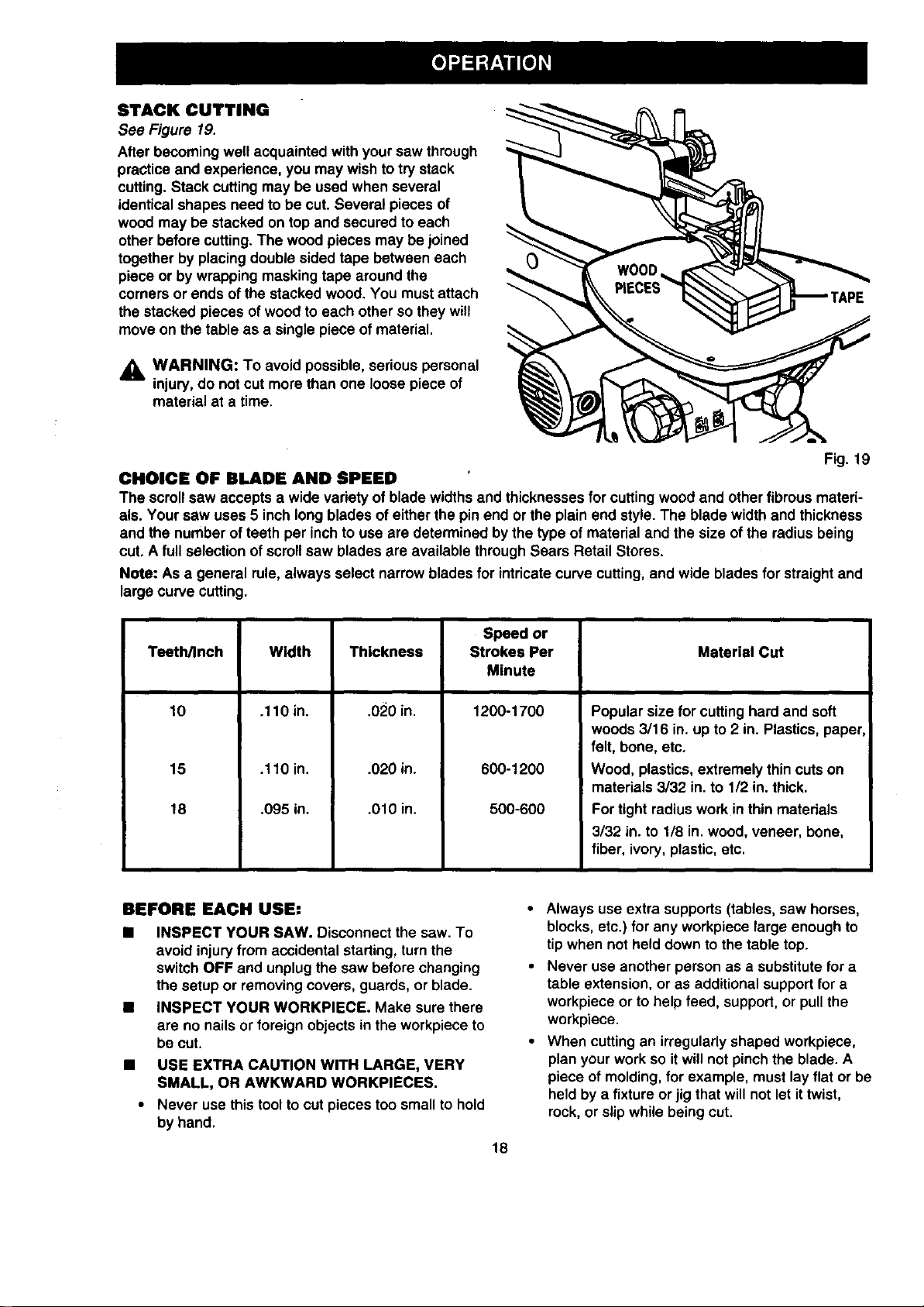
INTERIOR SCROLL CUTTING
See Figure 18.
• One ofthe features of a scroll saw isthat it can
be used to make scroll cutson the interiorof a
board without breaking or cuttingthrough the
edge or perimeter of the board.
&
WARNING: To avoid possibleserious injury
from accidental starting,always turn the switch
OFF and remove plugfrom power source outlet
before removingor replacing the blade.
• To make interiorcuts in a board, remove the
scroll saw blade as explained in the Installing
Blades sectionon page 14.
• Drilla 114in. hole in the board to be used to
make interiorcuts.
• Place the board on the saw table withthe hole in
the board over the access hole in the table.
• Installblade through hole in board then adjust
the holddown foot and the blade tension. See
pages 14 and 15.
• When finished makingthe interiorscrollcuts,
simplyremove the blade from the blade holders
as describedin the Installing Blades section,
and remove the board from the table.
DRILLHOLE
INTERIOR
PADLOCK
ON/OFFKNOB
Fig. 17
Fig. 18
17
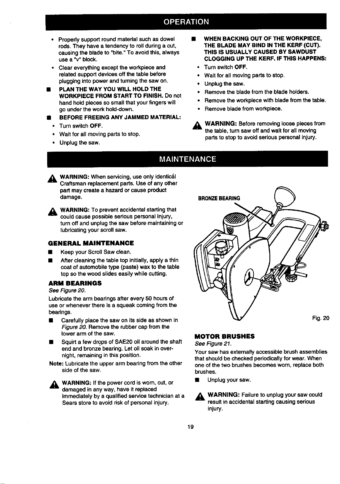
STACK CUTTING
See Figure 19.
After becoming well acquainted with yoursaw through
practice and experience, you may wish to trystack
cutting.Stack cutting may be used when several
identicalshapes need to be cut. Several pieces of
wood may be stacked on top and secured to each
other before cutting.The wood pieces may be joined
together by placingdouble sided tape between each
piece or by wrapping maskingtape around the
comers or ends of the stacked wood. You mustattach
the stacked pieces of woodto each other so they will
move on the table as a single piece of material.
_k WARNING: To avoid possible, serious personal
injury,do not cut more than one loose piece of
material at a time.
0
Fig. 19
CHOICE OF BLADE AND SPEED
The scroll saw accepts a wide variety of blade widthsand thicknessesfor cutting wood and other fibrousmateri-
als. Your saw uses 5 inch long blades of either the pin end or the plain end style. The blade width and thickness
and the number of teeth per inchto use are determined by the type of material and the size of the radius being
cut. A full selection of scrollsaw blades ere available through Sears Retail Stores.
Note: As a general rule, always select narrow blades for intricatecurve cutting,and wide blades for straightand
large curve cutting.
Teeth/Inch
10
15
18
Width
.110 in.
.110 in.
.095 in.
Thickness
.020 in.
.020 in.
.010 in.
Speed or
Strokes Per Material Cut
Minute
1200-1700
600-1200
500-600
Popular size for cutting hard and soft
woods 3116 in. up to 2 in. Plastics,paper,
felt, bone, etc,
Wood, plastics, extremely thincutson
materials 3/32 in.to 1/2 in.thick.
Fortight radius work in thinmaterials
3/32 in. to 1/8 in. wood, veneer, bone,
fiber, ivory, plastic, etc.
BEFORE EACH USE:
• INSPECT YOUR SAW. Disconnect the saw. To
avoid injuryfrom accidental starting, turnthe
switch OFF and unplugthe saw before changing
the setup or removing covers, guards, or blade.
• INSPECT YOUR WORKPIECE. Make sure there
are no nailsor foreign objects in the workpiece to
be cut.
• USE EXTRA CAUTION WITH LARGE, VERY
SMALL, OR AWKWARD WORKPIECES.
• Never use this tool tocut pieces too small to hold
by hand.
18
• Always use extra supports (tables, saw horses,
blocks, etc.) for any workpiece large enough to
tip when not held down tothe table top.
• Never use another person as a substitutefor a
table extension, or as additionalsupportfor a
workpiece or to help feed, support, or pullthe
workpiece.
• When cuttingan irregularlyshaped workpiece,
planyour work so itwillnot pinchthe blade. A
piece of molding,for example, must layflat or be
held bya fixture orjig that willnot let ittwist,
rock,or slip while being cut.
Properlysupportroundmaterialsuchasdowel
rods.Theyhaveatendencytorollduringacut,
causingthebladeto"bite." To avoidthis, always
use a "v" block.
• Clear everything except the workpiece and
related supportdevices offthe table before
plugginginto power and turningthe saw on.
B PLAN THE WAY YOU WILL HOLD THE
WORKPIECE FROM START TO FINISH. Do not
hand hold pieces so small that yourfingers will
go under the work hold-down.
• BEFORE FREEING ANY JAMMED MATERIAL:
• Turn switch OFF.
• Wait for all moving parts to stop.
• Unplug the saw.
WHEN BACKING OUT OF THE WORKPIECE,
THE BLADE MAY BIND IN THE KERF (CUT).
THIS IS USUALLY CAUSED BY SAWDUST
CLOGGING UP THE KERF. IF THIS HAPPENS:
• Turn switch OFF,
• Wait for all moving parts to stop.
• Unplug the saw.
• Remove the blade from the blade holders.
• Remove the workpiece with blade from the table.
• Remove blade from workpiece.
&
WARNING: Before removing loosepieces from
the table, turnsaw off and waitfor all moving
parts to stop to avoid serious personal injury.
_. WARNING: When servicing, use onlyidentic&l
Craftsman replacement parts. Use of any other
part may create a hazard or cause product
damage.
WARNING: To prevent accidental starting that
could cause possible serious personal injury,
turn offand unplug the saw before maintainingor
lubricatingyour scroll saw.
GENERAL MAINTENANCE
Keep your Scroll Saw clean.
After cleaning the table top initially,apply a thin
coat of automobile type (paste) wax to the table
top so the wood slides easily while cutting.
ARM BEARINGS
See Figure 20.
Lubricatethe arm bearings after every 50 hours of
use or whenever there is a squeak coming from the
bearings.
• Carefully place the saw on itsside as shown in
Figure 20. Remove the rubber cap from the
lower arm of the saw.
• Squirt a few drops of SAE20 oil around the shaft
end and bronze bearing. Let oil soak in over-
night, remaining in this position.
Note: Lubricatethe upper arm bearing from the other
side of the saw.
_k, WARNING: Ifthe power cord isworn, cut, or
damaged in any way, have it replaced
immediately by a qualified service technician at a
Sears store to avoid riskof personal injury.
BRONZEBEARING
MOTOR BRUSHES
See Figure21.
Your saw has externally accessible brush assemblies
that should be checked periodicallyfor wear. When
one of the two brushes becomes worn, replace both
brushes.
• Unplug your saw.
_, WARNING: Failure to unplugyour saw could
resultin accidental starting causing serious
injury.
19
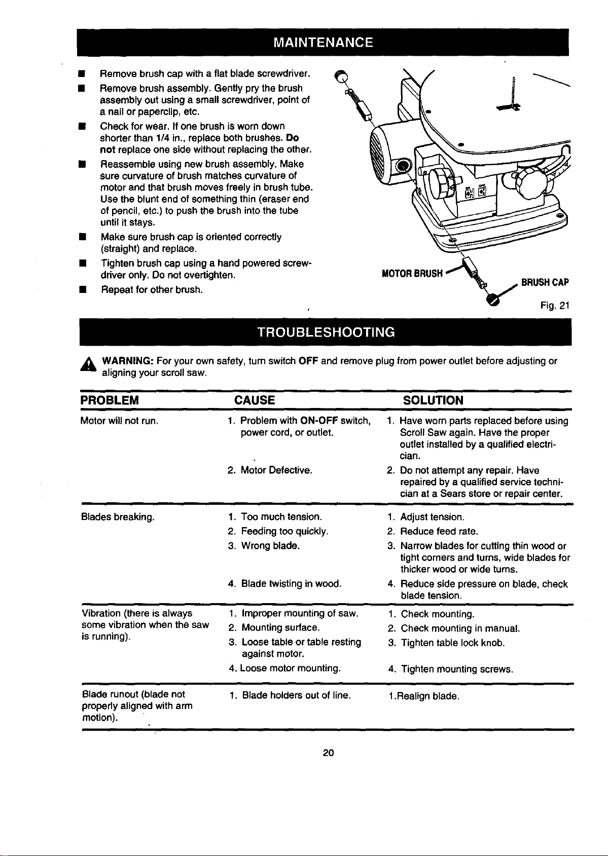
• Remove brush cap with a flat blade screwdriver.
• Remove brush assembly. Gently pry the brush
assembly out using a small screwdriver, point of
a nail or paperclip, etc.
• Check for wear. If one brush is worndown
shorter than 114in., replace both brushes. Do
not replace one side without replacing the other.
• Reassemble using new brush assembly. Make
sure curvature ofbrush matches curvature of
motorand that brush moves freely in brushtube.
Use the blunt end of somethingthin (eraser end
of pencil, etc.) to pushthe brush intothe tube
until itstays.
• Make sure brushcap is oriented correctly
(straight) and replace.
• Tighten brush cap usinga hand powered screw-
ddver only. Do not overtighten.
• Repeat for other brush.
\
_j_1. BRUSHCAP
Fig. 21
,_ WARNING: For your own safety, turnswitch OFF and remove plug from poweroutlet before adjusting or
aligning your scrollsaw.
PROBLEM CAUSE SOLUTION
Motor will not run. 1. Problemwith ON-OFF switch, I.
power cord, or outlet.
2. Motor Defective. 2,
Have worn parts replaced before using
Scroll Sew again. Have the proper
outlet installedby a qualified electri-
cian.
Do notattempt any repair. Have
repaired by a qualified service techni-
cian at a Sears store or repair center.
Blades breaking.
Vibration (there is always
some vibration when the saw
is running).
1. Too much tension. 1. Adjust tension.
2, Feeding too quickly. 2. Reduce feed rate.
3, Wrong blade. 3.
4. Blade twistingin wood. 4.
Narrow blades for cuttingthin wood or
tight corners and turns, wide blades for
thicker wood or wide turns,
Reduce side pressure on blade, check
blade tension.
1. Improper mounting of saw.
2. Mounting surface.
3. Loose table or table resting
against motor.
4. Loose motor mounting. 4. Tighten mounting screws.
Blade runout (blade not 1. Blade holders out of line. 1.Realign blade.
properly aligned with arm
motion).
20
1. Check mounting.
2. Check mounting in manual.
3. Tighten table lock knob.

21
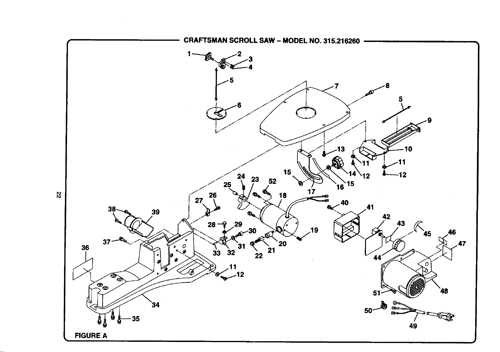
CRAFTSMAN SCROLL SAW - MODEL NO. 315.216260
Po
r_
39
36
_-35
34
/-/
/*°
/
./'/" 15
/'/25 24 23
52
26 18
27
28 29
33 32 22 21
17
16 15
49
FIGURE A

Po
Co
Key
No.
1
2
3
4
5
6
7
8
9
10
11
12
13
14
15
16
17
18
19
20
21
22
23
24
25
26
Pert
Number
979817-001
980119-001
979814-001
979813-001
979832-001
979810-001
979809-001
979807-001
979806-001
979729-001
979730-001
979808-001
979805-001
979804-001
979803-001
979802-001
980123-001
979788-001
979786-001
979785-001
979784-001
979775-001
979776-001
979774-001
979773-001
CRAFTSMAN SCROLL SAW - MODEL NO. 315.216260
PARTS LIST FOR FIGURE A
Description Ouan.
Blade Lock Knob........................................... 1
Blade Holder ................................................. 1
Spring Pin ..................................................... 1
Spring Pin ..................................................... 1
Saw Blade..................................................... 1
Throat Plate .................................................. 1
Table ............................................................. 1
Table Screw .................................................. 1
Blade Drawer ................................................ 1
Blade Drawer Bracket................................... 1
Washer ......................................................... 3
Screw (Pan Hd.) ........................................... 3
Screw (Pan Hd.) ........................................... 2
Bevel Lock Knob........................................... 1
Flat Washer .................................................. 2
Scale ............................................................. 1
Miter Scale Bracket ...................................... 1
Motor (Includes Kay Nos. 19, 20, 21, & 22). 1
Clamp Screw ................................................ 2
Brush Holder ................................................. 2
Brush Assembly............................................ 2
Brush Cap ..................................................... 2
Counterbalance ............................................ 1
Clamp Screw ................................................ 1
Spacer .......................................................... 1
Screw (Pan Hd.) ........................................... 1
Key Part
No. Number
27 979772-001
28 979820-001
29 979821-001
30 979822-001
31 979823-001
32 979824-001
33 979825-001
34 979771-001
35 979769-001
36 979768-001
37 979770-001
38 979766-001
39 979767-001
40 979801-001
41 979800-001
42 979799-001
43 979798-001
44 979797-001
45 979796-001
46 979794-001
47 979793-001
48 979795-001
49 979790-001
50 979791-001
51 979789-001
52 979777-001
Description Quan.
Indicator........................................................ 1
Hex Bolt ........................................................ 1
Hex Nut ......................................................... 1
Hex Bolt (Socket Hd. Special) ...................... 1
Washer ......................................................... 1
Stopper ......................................................... 1
SpringPin ..................................................... 1
Base.............................................................. 1
Hex Bolt ........................................................ 4
Waming Label............................................... 1
Hex Bolt ........................................................ 3
Screw (Pan Hd.) ........................................... 2
Nozzle ........................................................... 1
Screw (Pan Hd.) ........................................... 2
Control Box ................................................... t
PC Board Assembly ..................................... t
Gasket .......................................................... 1
On/Off Knob .................................................. 1
Knob Label.................................................... 1
Motor Pointer ................................................ t
Switch Label ................................................. t
Motor Cover .................................................. 1
Power Cord Assembly.................................. 1 "
Strain Relief .................................................. 1
Screw (Pan Hd.) ........................................... 4
Motor Screw.................................................. 3
*** Available at your nearest Sears Retail Store.
CRAFTSMAN SCROLL SAW - MODEL NO. 315.216260
j:.
29
30
28
21
13
20
12
14
12
18
16
15
37
38
39
40
FIGURE B

Po
O1
I
Key
No.
1
2
3
4
5
6
7
8
9
10
11
12
13
14
15
16
17
18
19
2O
21
22
23
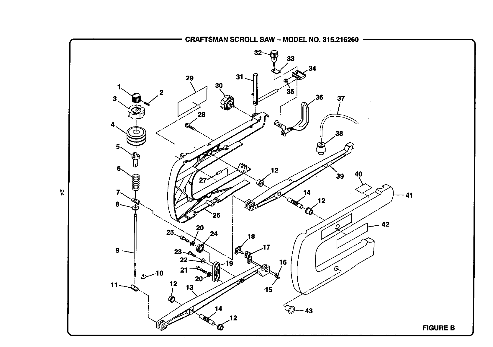
CRAFTSMAN SCROLL SAW - MODEL NO. 315.216260
I
The model number willbe found on a plate attached to the frame. Always mention the modelnumber in all correspondence regarding your SCROLL |
SAW or when orderingrepair parts.
I
Pad
Number
979827-001
979737-001
979736-001
979742-001
979735-001
979766-001
979734-001
979828-001
979733-001
979830-001
979732-001
979765-001
979763-001
979764-001
979814-001
979813-001
980119-001
979817-001
979762-001
979731-001
979761-001
979760-001
979769-001
PARTS LIST FOR FIGURE A
Description Quart.
Tension AdjustingKnob........................... ,... 1
SpringPin ..................................................... 1
Quick Release Knob ..................................... 1
Rubber Boot.................................................. 1
Cam .............................................................. 1
Arm Spdng .................................................... 1
Tension Wedge ............................................. 1
Washer ......................................................... 1
Tension Bolt.................................................. 1
E-Ring ........................................................... 1
TensionWedge ............................................. 1
Bushing......................................................... 4
LowerArm .................................................... 1
Spacer Bearing ............................................. 2
SpringPin ..................................................... 1
Spring Pin ..................................................... 1
Blade Holder................................................. 1
Blade Lock Knob ........................................... 1
Link ............................................................... 1
Spdng Washer .............................................. 2
Screw (Socket Hd. Cap) ............................... 1
Washer ......................................................... 2
Screw (Pan Hd.) ........................................... 2
Key Pad
No. Number
24 979758-001
25 979826-001
26 979752-001
27 979751-001
28 979740-001
29 979738-001
30 979741-001
31 979831-001
32 979744-001
33 979745-001
34 979749-001
35 979743-001
36 979747-001
37 979746-001
38 979748-001
39 979753-001
40 979754-001
41 979755-001
42 979757-001
43 979829-001
972000-549
Description Quen.
Ball Beadng .................................................. 2
Bolt (Hex Hd.) ............................................... 1
Right Arm Cover ........................................... 1
Spring Pin ..................................................... 1
Screw (Pan Hd.) ........................................... 8
Data Plate ..................................................... 1
Hold Down Foot Lock Knob.......................... 1
Support Bar Assembly.................................. 1
Foot AdjustingKnob ..................................... 1
SupportPlate ................................................ 1
Hold Down Clamp ......................................... 1
Washer/Spacer ............................................. 1
Hold Down Foot............................................ 1
AirHose ........................................................ 1
Air Diaphragm............................................... 1
Upper Arm .................................................... 1
Hand Warning Label ..................................... 1
LeftArm Cover.............................................. 1
Logo Plate..................................................... 1
Rubber Stopper ............................................ 3
Owners Manual
* Standard Hardware Item -- May Be Purchased Locally ** Available From Division 98 - Source 980.00

For in-home major brand repair service:
Call 24 hours a day, 7 days a week
1-800-4-MY-Home TM (1-800-469-4663)
Para pedir servicio de reparacibn a domicilio - 1-800-676-5811
In Canada for all your service and parts needs call
- 1-800-665-4455
Au Canada pour tout le service ou les pi_ces
For the repair or replacement parts you need:
Call 7 am - 7 pm, 7 days a week
1-800-366-PART (1-800-366-7278)
Para ordenar piezas con entrega a domicilio - 1-800-659-7084
For the location of a Sears Parts and Repair Center in your area:
Call 24 hours a day, 7 days a week
1-800-488-1222
For information on purchasing a Sears Maintenance Agreement
or to inquire about an existing Agreement:
Call 9 am - 5 pm, Monday - Saturday
1-800-827-6655
The Service Side of Sears s"