
1
Installation Manual
UNDERCOUNTER REFRIGERATION
Beer Dispensers
INDOOR / OUTDOOR
EN
©2021 Hestan Commercial Corporation
2
2 SAFETY DEFINITIONS
3 MODEL NUMBERS
3 KEG LAYOUT
4 RATING LABEL
4 REGULATORY/CODE REQUIREMENTS
4 SAFETY
6
CABINET INSTALLATION
9
DOOR INFORMATION
11 INSTALLATION OF DISPENSING EQUIPMENT
17 CONNECTING THE REGULATOR TO THE CO
2
CYLINDER
19 DISPOSAL
TABLE OF CONTENTS
SAFETY DEFINITIONS
READ THESE INSTRUCTIONS CAREFULLY AND COMPLETELY
BEFORE INSTALLING OR USING YOUR APPLIANCE TO REDUCE
THE RISK OF FIRE, SHOCK HAZARD, OR OTHER INJURY. KEEP
THIS MANUAL FOR FUTURE REFERENCE.
IMPORTANT! IMPORTANT! The installation of the actual beer dispenser cabinet should
happen prior to installing the dispensing equipment. Refer to the Cabinet
Installation section of this manual for step-by-step instructions.
IMPORTANT! IMPORTANT! Read and understand all information in this manual before
attempting the installation. All plumbing and electrical work must be performed
by a qualified technician and conform to all applicable state and local codes.
INSTALLER: LEAVE THIS MANUAL WITH THE OWNER OF THE APPLIANCE.
HOMEOWNER: RETAIN THIS MANUAL FOR FUTURE REFERENCE.
THIS INDICATES A HAZARD THAT WILL RESULT IN SERIOUS
INJURY OR DEATH IF PRECAUTIONS ARE NOT FOLLOWED.
THIS INDICATES A HAZARD THAT MAY RESULT IN SERIOUS
INJURY OR DEATH IF PRECAUTIONS ARE NOT FOLLOWED.
THIS INDICATES A HAZARD WHERE MINOR INJURY
OR PRODUCT OR PROPERTY DAMAGE MAY OCCUR IF
PRECAUTIONS ARE NOT FOLLOWED.
THIS INDICATES THAT PRODUCT OR PROPERTY DAMAGE MAY
OCCUR IF PRECAUTIONS ARE NOT FOLLOWED.
DANGER
DANGER
RISK OF FIRE OR EXPLOSION - FLAMMABLE REFRIGERANT USED. Consult
repair manual/owners guide before attempting to service this product. All
safety precautions must be followed. To be repaired by trained service personnel only. Use caution
when handling, moving and using the product to avoid damaging the refrigerant tubing or increasing
the risk of a leak.
All service work shall be performed by factory authorized service personnel and
all component parts shall be replaced with like components to minimize the risk
of possible ignition due to incorrect parts or improper service.
If service is necessary, repair work must be performed by a Hestan authorized
servicer. Work done by unqualified individuals could potentially be dangerous
and will void the warranty.
NOTICE
EN
©2021 Hestan Commercial Corporation
3
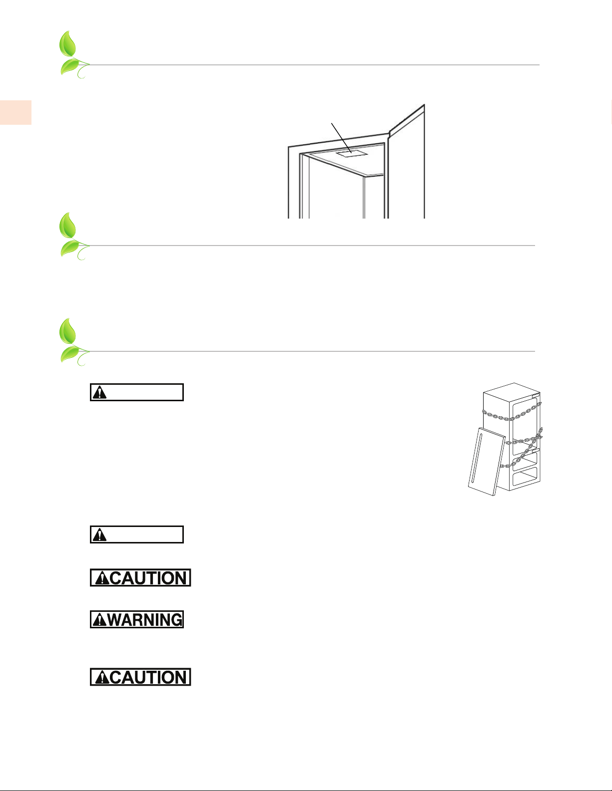
One 1/4 barrel
Standard = Ø16-
1
�
8
” x 13-
7
�
8
” H - 7.75 Gal [29.3 l]
Slim = Ø11-
1
�
8
” x 23-
3
�
8
” H - 7.75 Gal [29.3 l]
Two 1/6 barrel
Ø9-
1
�
4
” x 23-
3
�
8
” H - 5.16 Gal [19.8 l]
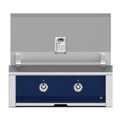
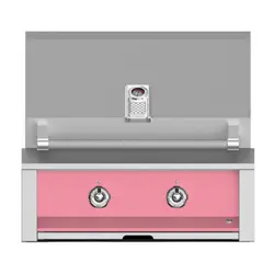
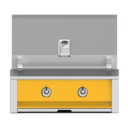
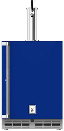
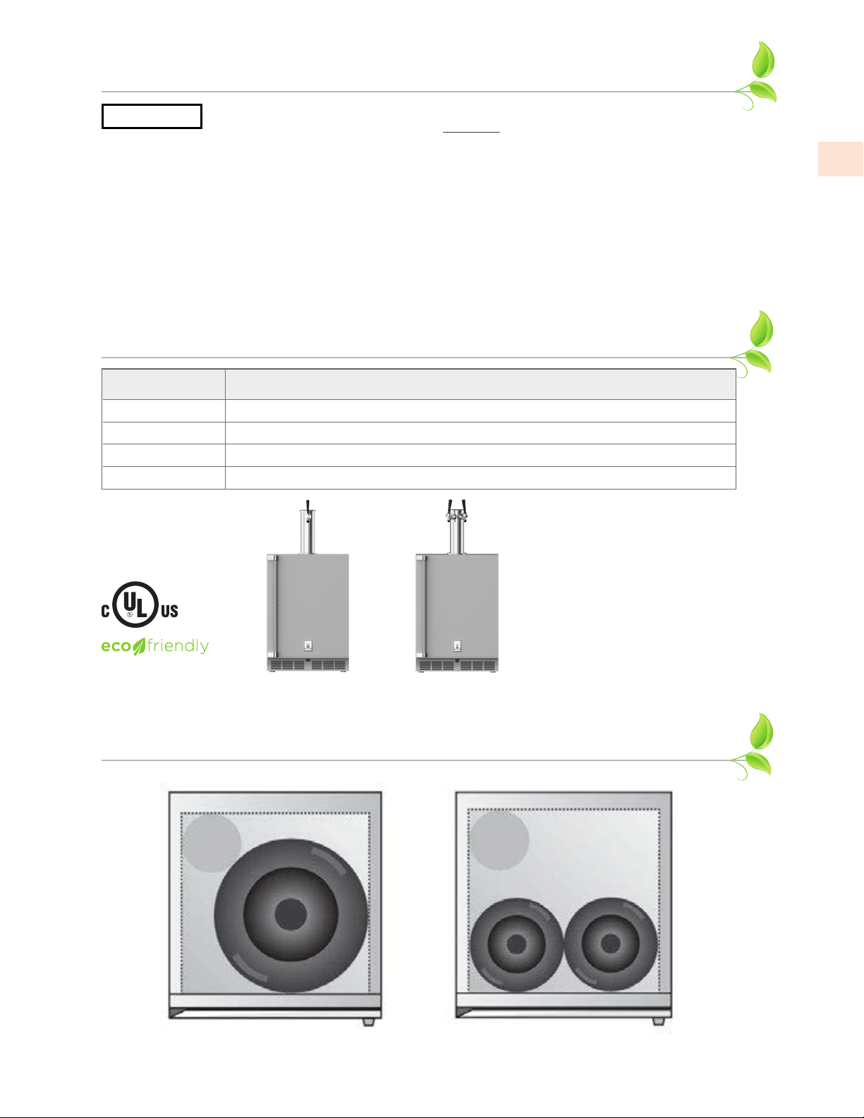
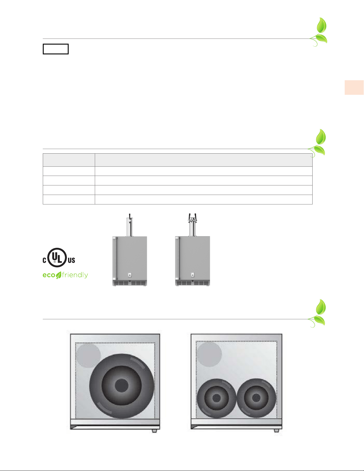
MODEL NUMBERS
Model No. Description
GFDS_241 INDOOR / OUTDOOR SINGLE FAUCET BEER DISPENSER, SOLID DOOR, 24”
GFDS_241-XX INDOOR / OUTDOOR SINGLE FAUCET BEER DISPENSER, SOLID DOOR, COLOR, 24”
GFDS_242 INDOOR / OUTDOOR DOUBLE FAUCET BEER DISPENSER, SOLID DOOR, 24”
GFDS_242-XX INDOOR / OUTDOOR DOUBLE FAUCET BEER DISPENSER, SOLID DOOR, COLOR, 24”
_ = Right (R) or Left (L) Hinged Model
GFDSR241
shown
GFDSR242
shown
KEG LAYOUT
The following standard beer kegs fit inside these units.
R600a Refrigerant
NOTICE
This product contains blown foam insulation using blowing agent R-611 (Methyl
Formate). The foam in this product does not contain HFC’s, CFC’s, or HCFC’s.
All models covered in this manual are manufactured using refrigerant R600a (Isobutane). R600a is
a hydrocarbon. This refrigerant is flammable and is only allowed for use in appliances which fulfill
the requirements of UL/IEC 60335-1 and UL/IEC 60335-2-24 (To cover potential risk originated from
the use of flammable refrigerants). Consequently, R600a is only allowed to be used in refrigerating
appliances which are designed for this refrigerant and fulfill the above-mentioned standard.
• R600a is heavier than air. The concentration will always be highest at the floor level.
• The explosion limits are as follows:
o Lower Limit: 1.8% by volume
o Upper Limit: 8.4% by volume
o Ignition Temperature: 860ºF [460°C]
SAFETY DEFINITIONS
(continued)
EN
©2021 Hestan Commercial Corporation
4
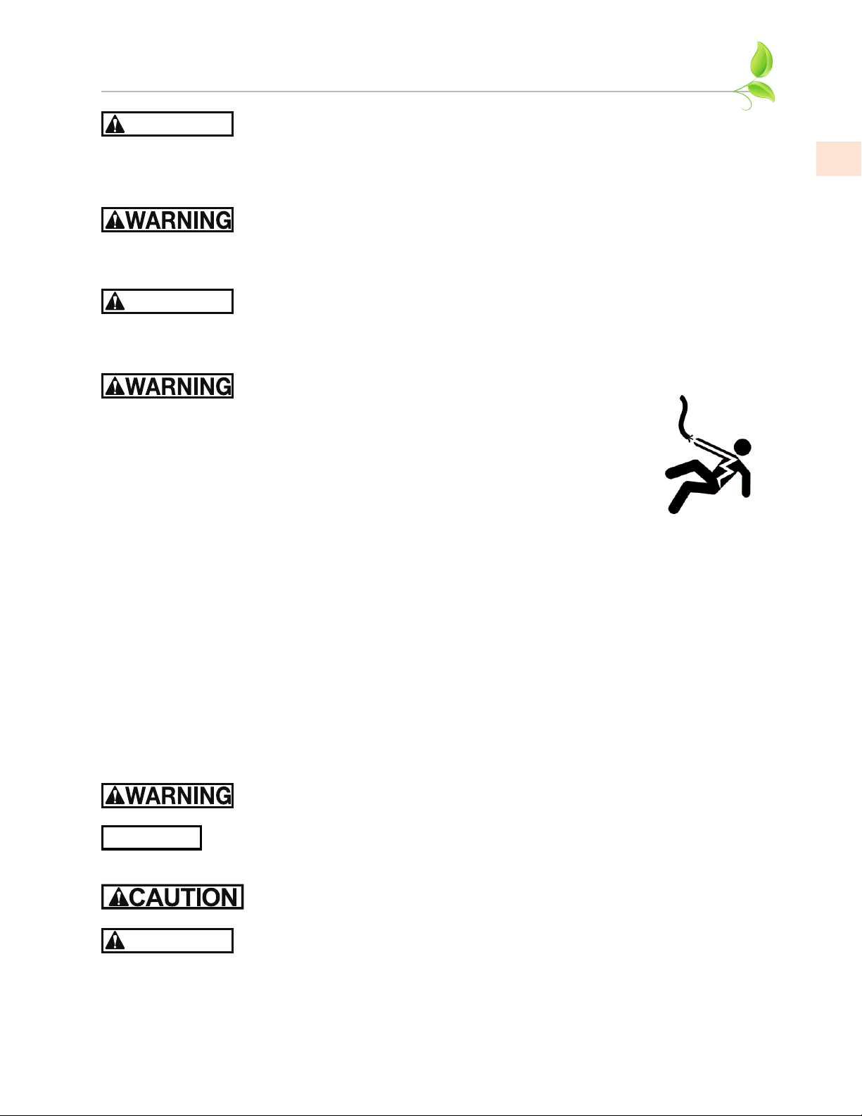
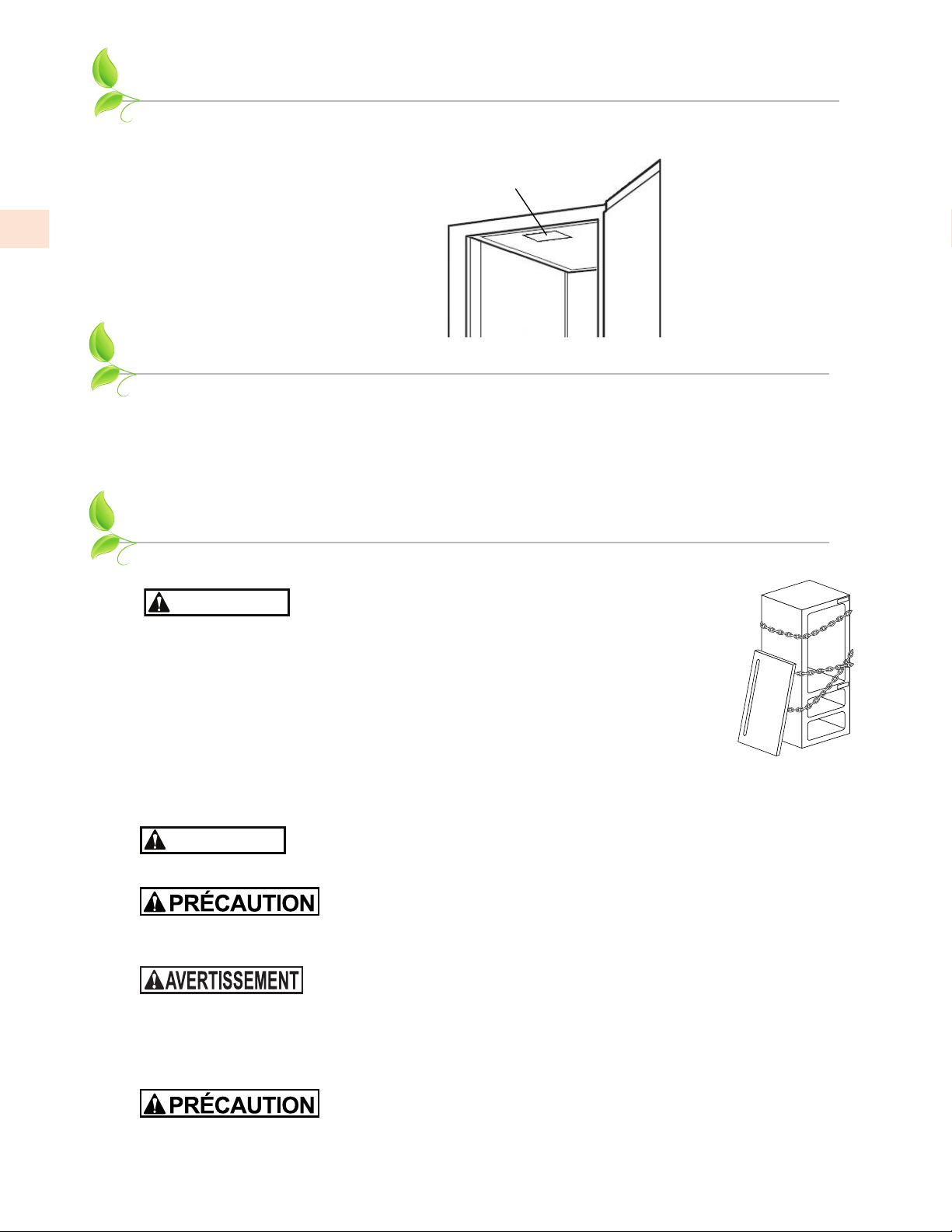
RATING LABEL
The rating label contains important information about your Hestan appliance such as the model and
serial number, and refrigerant information if service is required.
RATING LABEL
REGULATORY / CODE REQUIREMENTS
Installation of this appliance must be made in accordance with local codes. In the absence of local
codes, this unit should be installed in accordance with the National Electrical Code and local codes.
This appliance must be electrically grounded in accordance with local codes or in the absence of
local codes with the National Electrical Code
ANSI/NFPA 70
, or Canadian Electrical code
CSA
C22.1
.
SAFETY
CHILD SAFETYCHILD SAFETY
DANGER
Risk of child entrapment. Before you throw away your old
refrigerator or freezer:
• Take off the doors.
• Leave the shelves in place so that children may not easily climb inside.
NEVER allow children to play inside the appliance.
PRIOR TO INSTALLATIONPRIOR TO INSTALLATION
Carefully inspect cabinet for hidden damage. If damage is discovered, file your
claim immediately with the transport company. Hestan is not responsible for
damage in transit. Remove any packaging materials before operating.
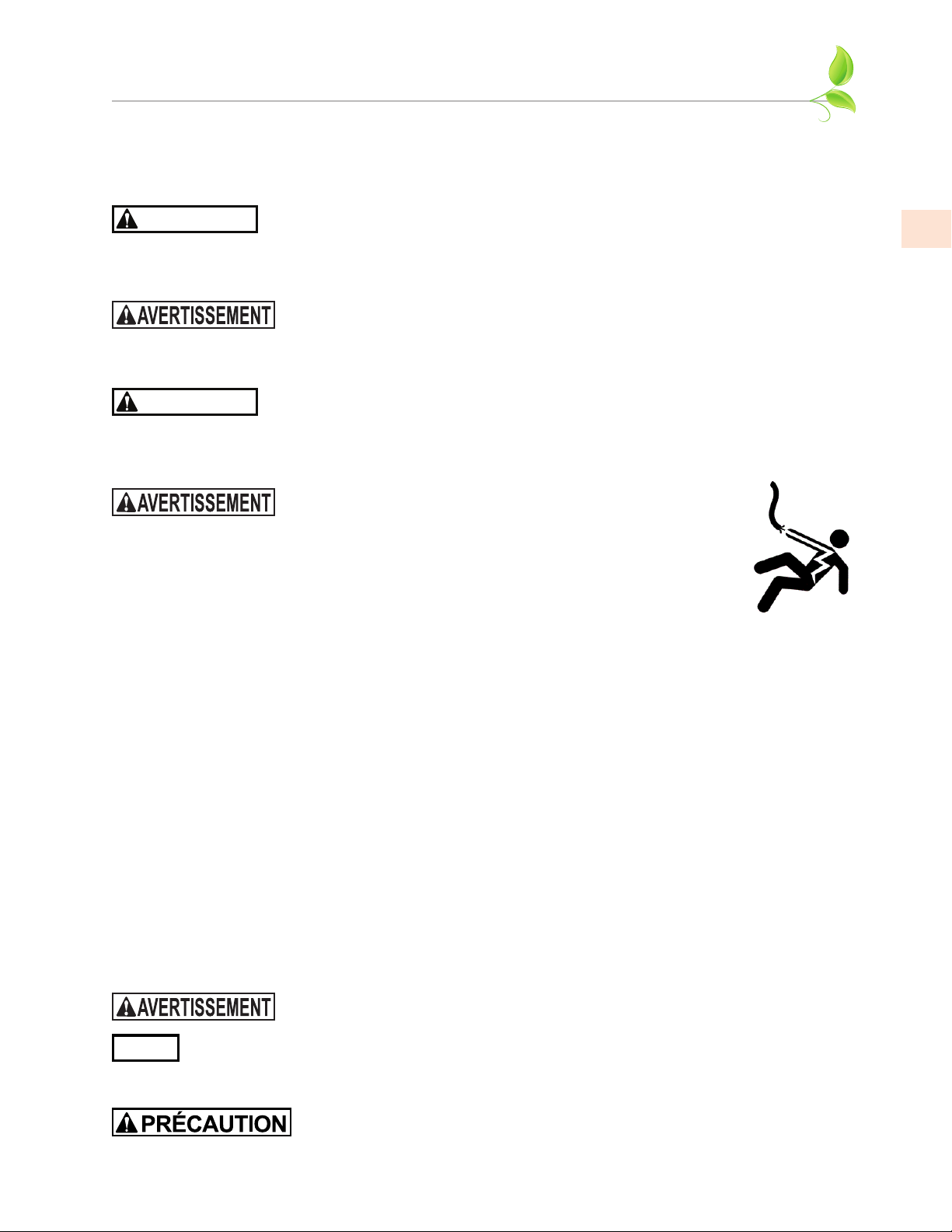
DANGER
RISK OF FIRE OR EXPLOSION - FLAMMABLE REFRIGERANT USED.
Use caution when handling, moving and using the product to avoid damaging
the refrigerant tubing or increasing the risk of a leak.
When moving the unit, be sure to protect finished flooring with appropriate
material to avoid damage from moving the unit. Do not lift unit by drawer,
shelving or door handles, as damage to the unit could occur if not moved as instructed.
To prevent personal injury, a minimum of two people are required to lift the
unit. Larger units may require additional personnel.
Before moving the unit, secure the door shut with tape to prevent door from swinging open while
being moved. Carefully move unit to installation site and place in front of opening.
If unit has been laid on its back or sides, place unit upright and allow a
minimum of 24 hours before connecting power.
PLUMBINGPLUMBING
Aside from connections to the beer tap and keg (see page 11), no other plumbing connections are
required. Condensate from the cooling coil is automatically evaporated through a condensate pan
located in the condensing section of the unit.
The rating label is attached to
the inside top of the cabinet.
EN
©2021 Hestan Commercial Corporation
5
DANGER
HIGH-PRESSURE GASHIGH-PRESSURE GAS
• Keep CO
2
cylinder away from heat. The rupture disc vents at 122°F [50°C] max.
• Do not drop or throw regulator or CO
2
cylinder.
• Allow only properly trained and experienced personnel to handle high-pressure gas.
• Do not apply oil to the regulator!
DANGER
ELECTRICAL SHOCK HAZARDELECTRICAL SHOCK HAZARD
Disconnect power before installing or servicing appliance. Failure to do so can result in death or
electrical shock.
ELECTRICAL GROUNDINGELECTRICAL GROUNDING
• This appliance must be grounded. Grounding reduces the risk of electric
shock in the event of a short circuit.
• DO NOT ground to a gas pipe.
• DO NOT use an extension cord with this appliance.
• DO NOT have a fuse in the NEUTRAL or GROUNDING circuit. A fuse in
the NEUTRAL or GROUNDING circuit could result in an electrical shock.
ELECTRICAL SUPPLYELECTRICAL SUPPLY
A 115 volt AC, 60 Hz, 15 Amp circuit breaker and electrical supply is required. A Ground Fault Circuit
Interrupter (GFCI) protected circuit must be used when installed outdoors.
This appliance is NOT designed for installation in manufactured (mobile) homes or recreational park
trailers.
All units are provided with a 5 ft [1.5 m] cord with three-prong grounding plug. It is imperative that
this plug be connected to a properly grounded three-prong receptacle. If the receptacle is not the
proper grounding type, contact an electrician. The receptacle must be flush or recessed into the wall
surface behind the unit.
• Never remove the grounding prong from this plug.
• Never use a 2-prong adapter.
• If a 2-prong receptacle is encountered, or a longer power cord is required, contract a qualified
electrician to have it replaced in accordance with applicable electrical codes.
Inspect the electrical cord and plug for damage prior to energizing the unit to
avoid potential electric shock.
NOTICE
The unit must NOT be totally enclosed or damage may occur. Air circulation must not
be restricted. The condenser at the cabinet front must be provided with a minimum of
2” [5 cm] air space. Be sure to provide access so the front cover can be removed to clean the condenser.
Do not attempt to operate the equipment on any power source / voltage other
than that listed on the Electrical Specification Plate attached to the unit.
DANGER
Do not store flammable liquids (i.e. Gasoline or Lighter Fluid) or vapors near the
appliance to avoid a fire.
ADDITIONAL GENERAL INFORMATIONADDITIONAL GENERAL INFORMATION
All electrical instructions assume the outlet is located 4 - 10” [10 - 25 cm] above the floor surface.
Floor must be level in area of installation. Leg levelers are used for fine-tune adjustment only and
should not be used to compensate for floor differences exceeding 1/2” [13 mm].
SAFETY
(continued)
EN
©2021 Hestan Commercial Corporation
6
CABINET INSTALLATION
DANGER
RISK OF FIRE OR EXPLOSION - FLAMMABLE REFRIGERANT USED.
Use caution when handling, moving and using the product to avoid damaging
the refrigerant tubing or increasing the risk of a leak.
CASTER KIT (OPTIONAL)CASTER KIT (OPTIONAL)
A Caster Kit (AGCK24) is available for Hestan refrigeration models. Refer to the instructions
supplied with the caster kit for proper installation.
Note: Installation of the kit adds 3.75” [9.5 cm] to overall height of the unit.
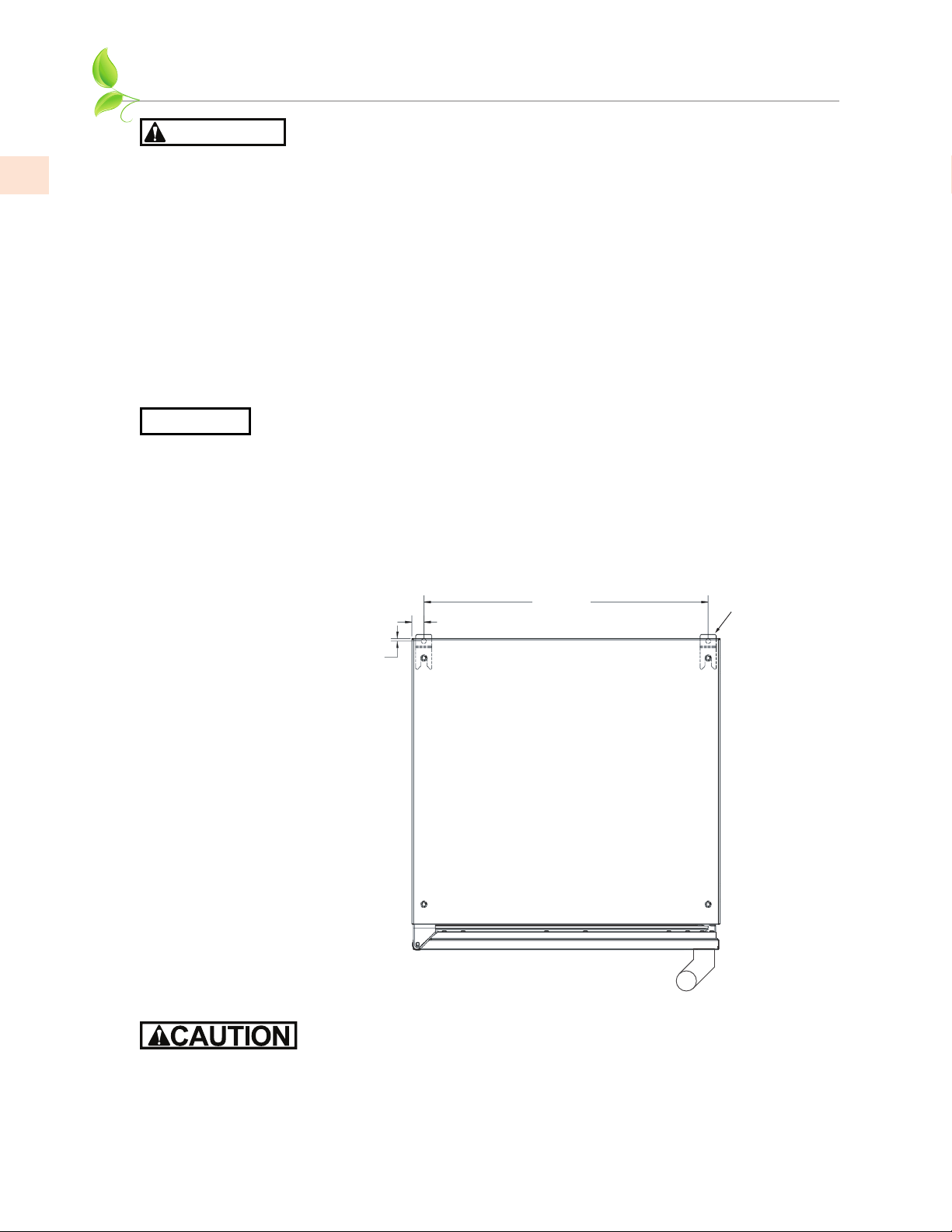
ANTI-TIP BRACKETSANTI-TIP BRACKETS
Unit may tip forward if loaded racks/shelves are all pulled out at the same time. To prevent tipping,
and to provide stable installation, the unit must be secured in place with the anti-tip brackets
supplied with the unit. The anti-tip brackets, when properly installed, should secure the rear legs/
glides to the mounting surface and prevent the unit from tipping forward.
NOTICE
Anti-tip brackets are only used for stationary cabinets and should not be installed on
cabinets with accessory casters.
If installing on a concrete floor, concrete fasteners are required and not included with the anti-tip kit.
Some installation sites may require modifications to provide a secure surface for attaching the
brackets.
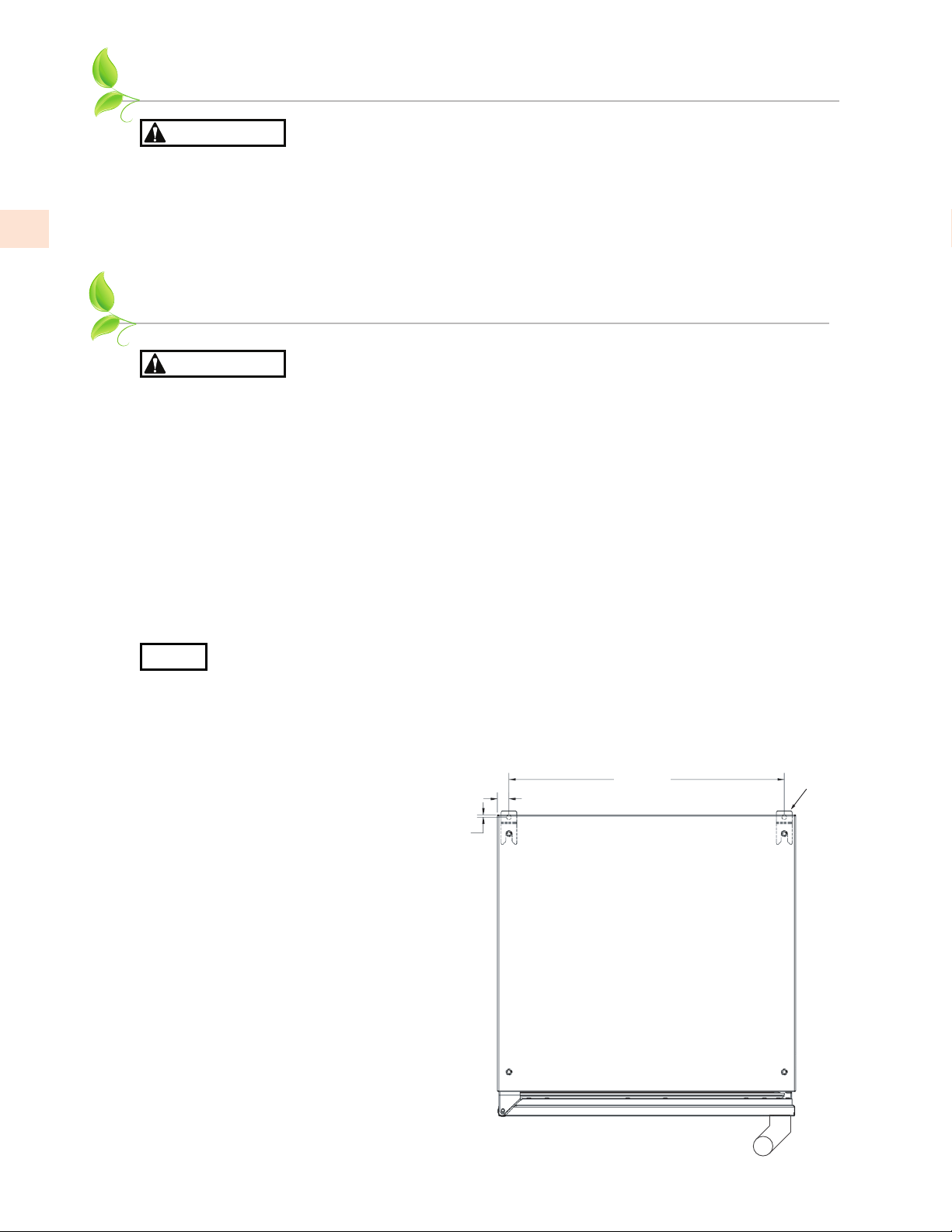
A set of anti-tip brackets is supplied with the unit. These brackets should be attached to the floor at
the rear of the unit. Each bracket must be located to engage the rear legs when the cabinet is pushed
back into position. Refer to Figure 1 (shown below) for anti-tip bracket mounting locations.
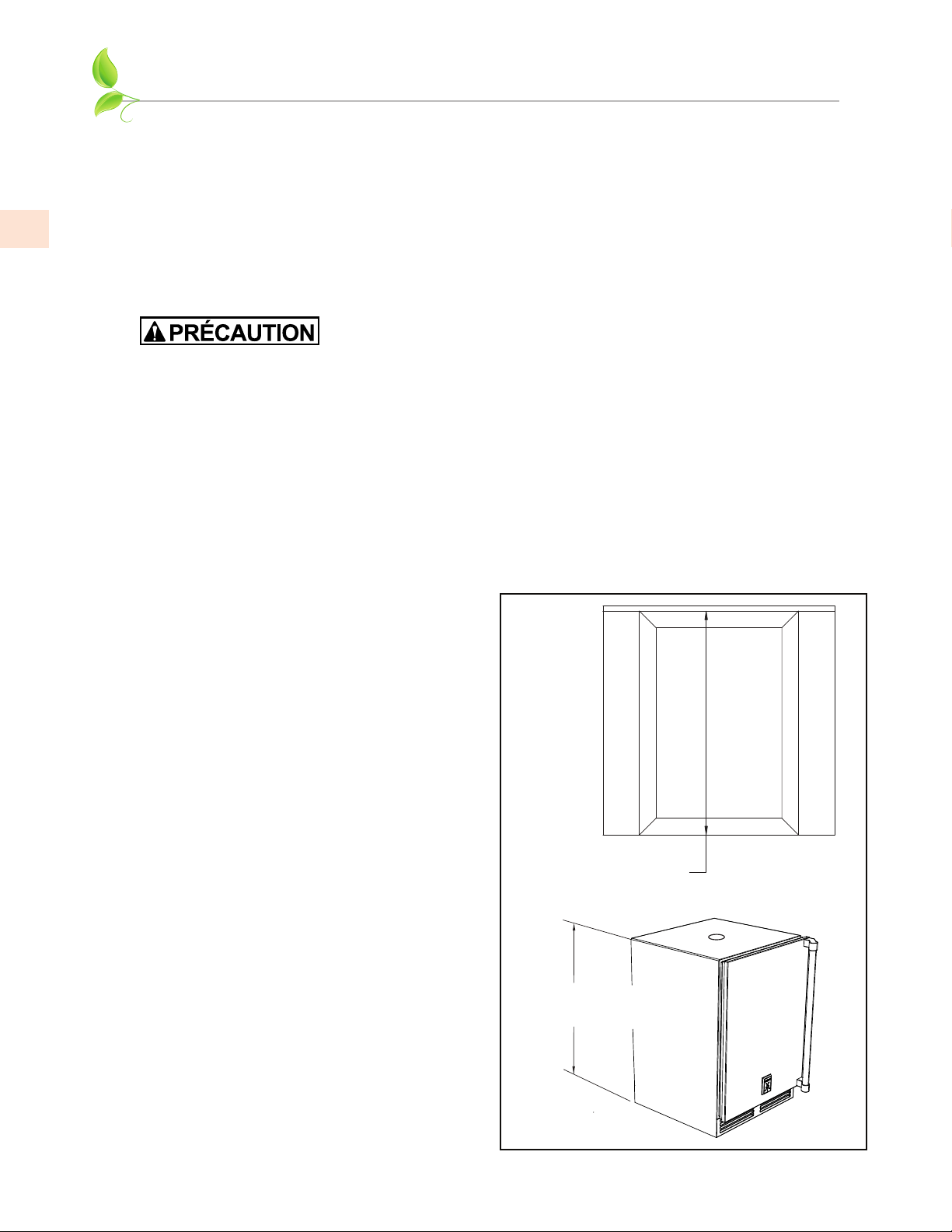
PREPARING THE SPACEPREPARING THE SPACE
If the unit is to be installed under a countertop, it is recommended that the countertop be supported
by a structure other than the unit itself to prevent damage to the unit.
Make sure the floor under the unit is level with the surrounding finished floor. Protect a finished
floor with plywood, cardboard, or some other suitable material before moving the unit into place.
Failure to do this may result in damage to the floor.
Figure 1. 24” Anti-Tip Kit
15
⁄16”
3
⁄16”
22-
3
⁄16”
BRACKETS
EN
©2021 Hestan Commercial Corporation
7
CABINET INSTALLATION
(continued)
To assure maximum performance, fresh air must be allowed to circulate through the machinery
compartment. Do not place anything in front of the unit that would obstruct air flow at these front
grilles. Do not place the unit in an unventilated small room.
NOTICE
Cabinet should be leveled front to back, then side to side.
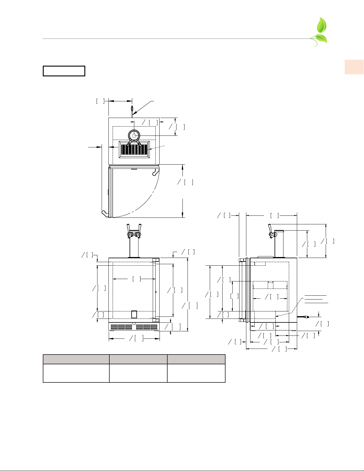
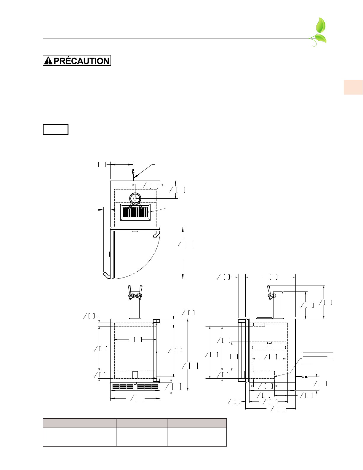
1. Make sure the space opening is correctly sized for the unit. See typical appliance dimensions
below, and the chart below for finished rough opening requirements:
HEIGHT WIDTH DEPTH
34-3/8” [87.3 cm] min.
35-1/2” [90.2 cm] max.
24” [61 cm] 24” [61 cm]
2. Check that the following are level and square:
• Front and interior opening
• Installation opening and floor surface
• Countertop bottom front edge
NOTE: For a door to open properly, the door must open a minimum of 90°. Use a minimum 3” [7.6
cm] filler in corner installations to assure a full 90° opening. Allow 25” [64 cm] clearance in front of
unit for full door swing and shelf/drawer pull out.
NOTE: The floor under the unit must be at the same level as the surrounding finished floor.
24" 611
3
16
" 84
5
12
3
4
" 323
15
1
2
" 394
24
15
16
"
633
16
"
7
214
8
11
15
16
"
303
11" 279
1
5
8
" 42
3
1
2
" 89
21
3
8
" 543
26
9
16
" 674
1
15
16
" 49
87234
5
"*
16
20" 508
14" 356
3
1
2
" 89
21
3
8
" 543
63224
7
8
"
*3
15
16
" 100
606
"
8
7
23
9
16
" 252
15
11
7
8
" 302
18
3
16
" 461
6
5
8
" 168
1
16
" 49
15
6
1
4
" 159
22
1
16
" 560
16
1
8
" 410
CUTOUT DIMENSIONS:
34-
3
⁄
8
” H - 24” W - 24” D
[873] H - [609] W - [609] D
TYPICAL APPLIANCE
DIMENSIONS
MIN. CLEARANCE
FOR DOOR SWING
90° SWING
REQUIRED FOR
PULL-OUT SHELF
CLEARANCE
POWER CORD
5 FT. LONG
3-
1
⁄
4
” [83] MIN. CLEARANCE
FROM A CORNER TO
ACHIEVE 90° SWING
*
- Leg levelers can add
3/4” to these dimensions
when fully extended.
Shelf included
with dispensing
cabinets.
Also fits two 1/6
barrels when
shelf is removed.
Portable Drainer
Typical 1/4 barrel.
EN
©2021 Hestan Commercial Corporation
8
CABINET INSTALLATION
(continued)
To prevent possible damage to the countertop, do not place heavy objects on
countertop directly over unit.
INSTALLING THE UNIT INTO THE SPACEINSTALLING THE UNIT INTO THE SPACE
1. Plug the unit into the 15 amp grounded electrical outlet located within the installation opening.
With power applied to the unit, check that the lighting and cooling functions operate properly.
Turn off the power to the wall outlet at the circuit breaker.
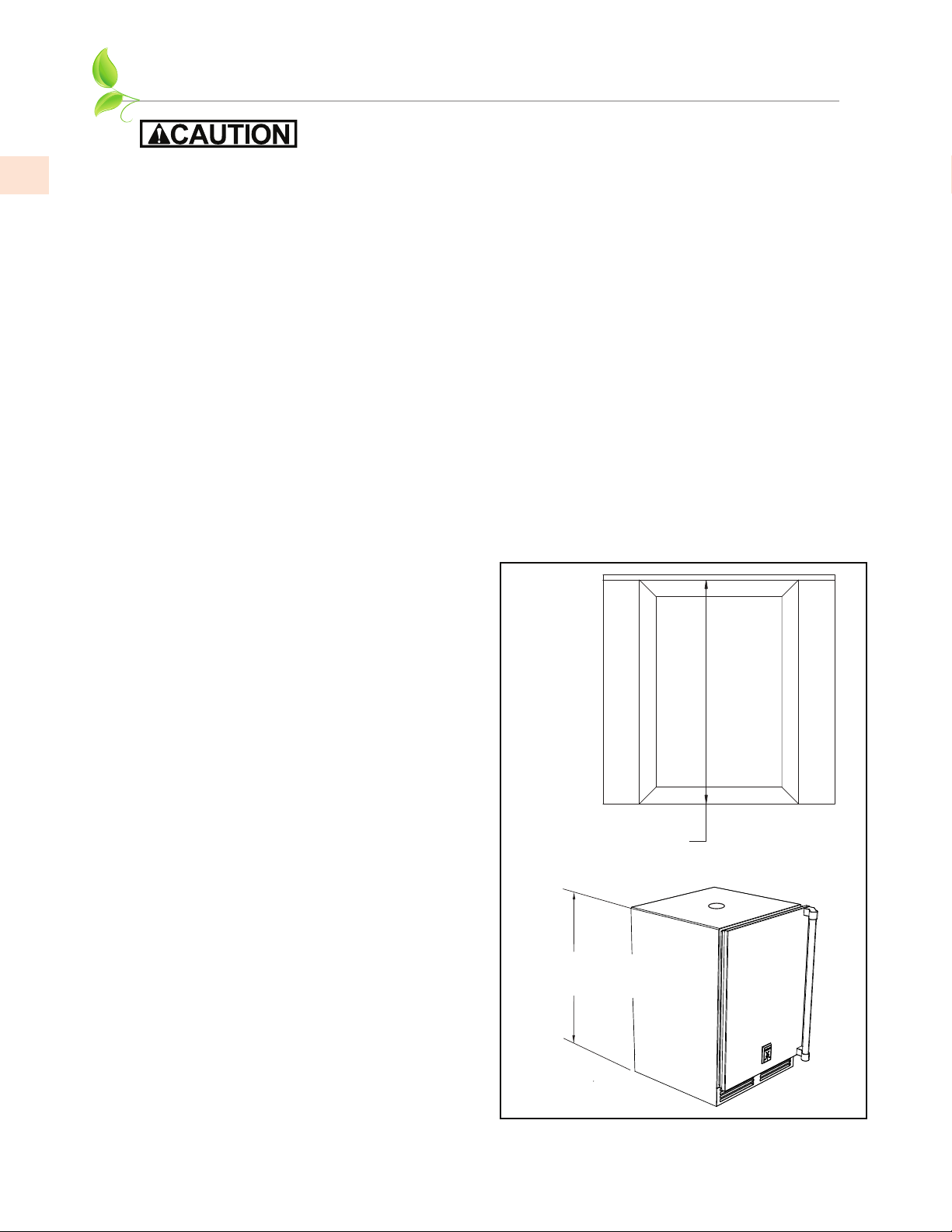
2. With all surfaces in the installation opening square and level, refer to Figure 2 below and perform
the following steps to level the unit:
• At the front of the opening, measure from the floor to the bottom of the front edge of the
countertop.
• Measure from the floor surface to the top of the unit at the rear corners.
• Adjust the unit legs so these two measurements are equal. Using an adjustable wrench or
pliers, turn legs clockwise to lower the unit or counterclockwise to raise it.
NOTE: Legs should not extend more than 3/4” [19 mm] from the bottom of the unit.
3. Slide the unit into position in the opening. Make sure the rear leveling legs slide under the ant-
tip brackets. Push the unit into the opening until the bottom front edge of the unit is flush with
the surrounding cabinetry, or until the rear legs are tight against the anti-tip brackets.
4. Shim the front of the unit so the front face is flush with the surrounding cabinetry. Adjust the
front legs to support the countertop at the shimmed height. Using an adjustable wrench or
pliers, turn the legs clockwise to lower the unit or counterclockwise to raise it. Countertop
should be resting on top of the unit.
NOTE: Countertop should be resting evenly
on entire top of the unit. Shim if necessary to
prevent damage to the countertop.
5. Check interior door openings to make sure
the unit is level and square. Install shelving.
6. Turn on the power to the wall outlet at the
circuit breaker.
Measure front of opening
from floor surface to bottom
edge of countertop.
Measure at both rear corners
of unit from floor surface to
bottom of countertop.
Figure 2. Leveling the Unit
EN
©2021 Hestan Commercial Corporation
9
CABINET INSTALLATION
(continued)
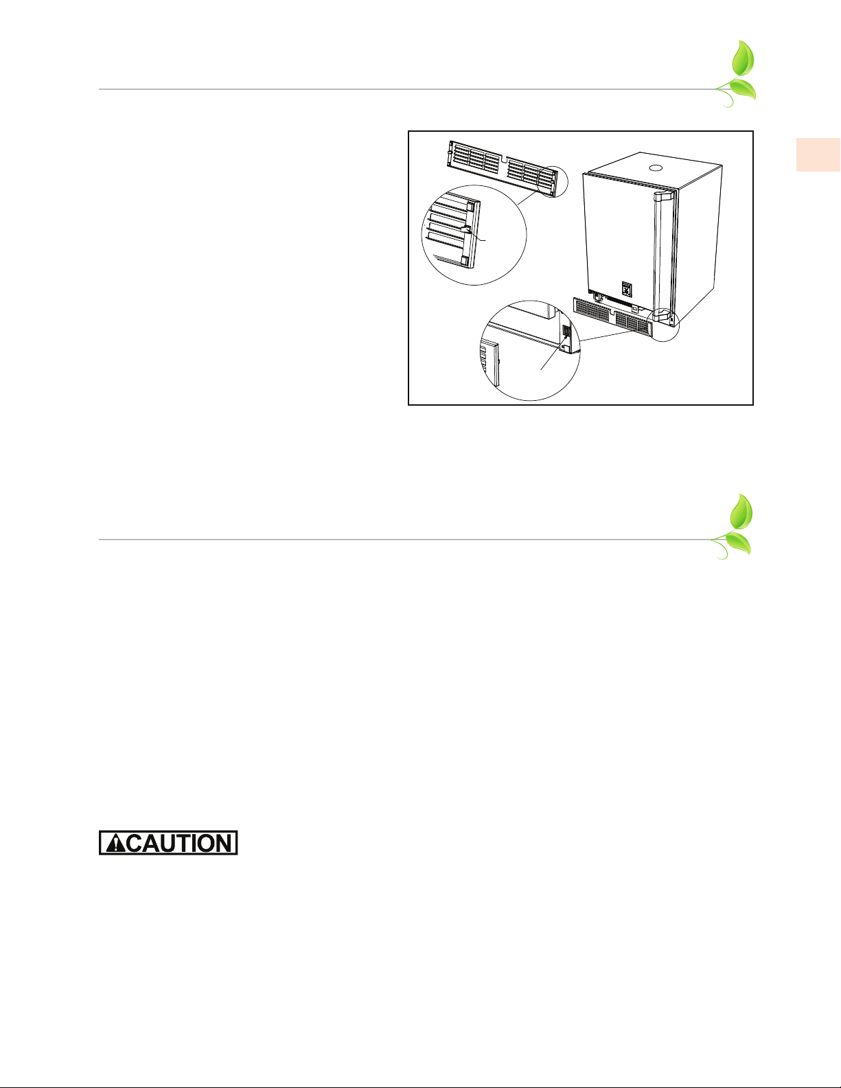
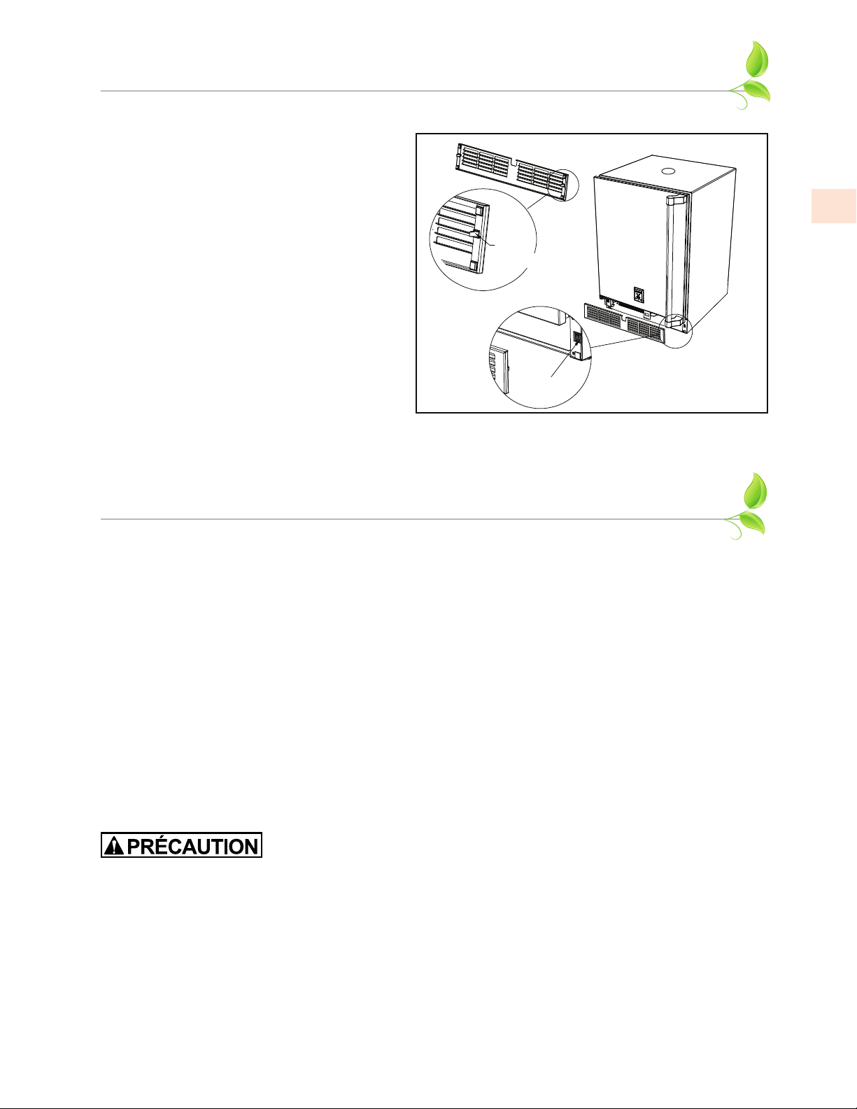
INSTALLING THE FRONT GRILLE COVERINSTALLING THE FRONT GRILLE COVER
Once the unit is secured in place, install the
louvered front grille cover. Secure the cover
by snapping the latch into the latch catch on
the unit (Figure 3).
The vent grille must be removed to service the
unit. The floor cannot interfere with removal,
and the louvered sections must not be covered
or obstructed. Obstructions could prevent
proper air circulation, which may damage the
unit.
NOTE: To achieve maximum performance,
interior louver openings and fan guard
openings should never be obstructed.
Latch
Catch
Latch
Figure 3. Front Grille Cover Installation
DOOR INFORMATION
DOOR OPTIONSDOOR OPTIONS
Hestan residential units can be converted from stainless steel to overlay panels to match existing
cabinetry. Solid doors are shipped from the factory with stainless steel panels and handles in place
on the unit. All stainless steel doors are convertible to fully integrated models, ready to accept
custom panels from your cabinetry supplier. You can contact Hestan Customer Care to send you any
of the following templates, or download directly from the Hestan website at
www.hestanoutdoor.com.
028370 - Template, Overlay, 24” Solid Door, Undercounter Refrigeration
028371 - Template, Overlay, 24” Toe Kick/Grille, Undercounter Refrigeration
028374 - Installation Instructions, Overlay Door/Drawer, Undercounter Refrigeration
Take care in choosing the correct template for your specific unit. The original appliance handle or
custom cabinet handle can be installed onto your overlay panel.
HANDLE INSTALLATIONHANDLE INSTALLATION
The handle mounting on the wood overlay should be mounted on the overlay only (not the actual
door) to avoid damage to the factory door. Proper woodworking materials and equipment should be
used to avoid damage or errors in workmanship.
1. Handle must be attached to the overlay before mounting the overlay onto the door. Mark the
rear of the wood overlay panel with handle fastening locations.
2. Drill through the wood overlay panel at marked locations, taking care not to damage the panel.
3. Countersink screw heads so that screw heads are flush with the back side of the panel. Attach
the handle to the overlay panel.
EN
©2021 Hestan Commercial Corporation
10
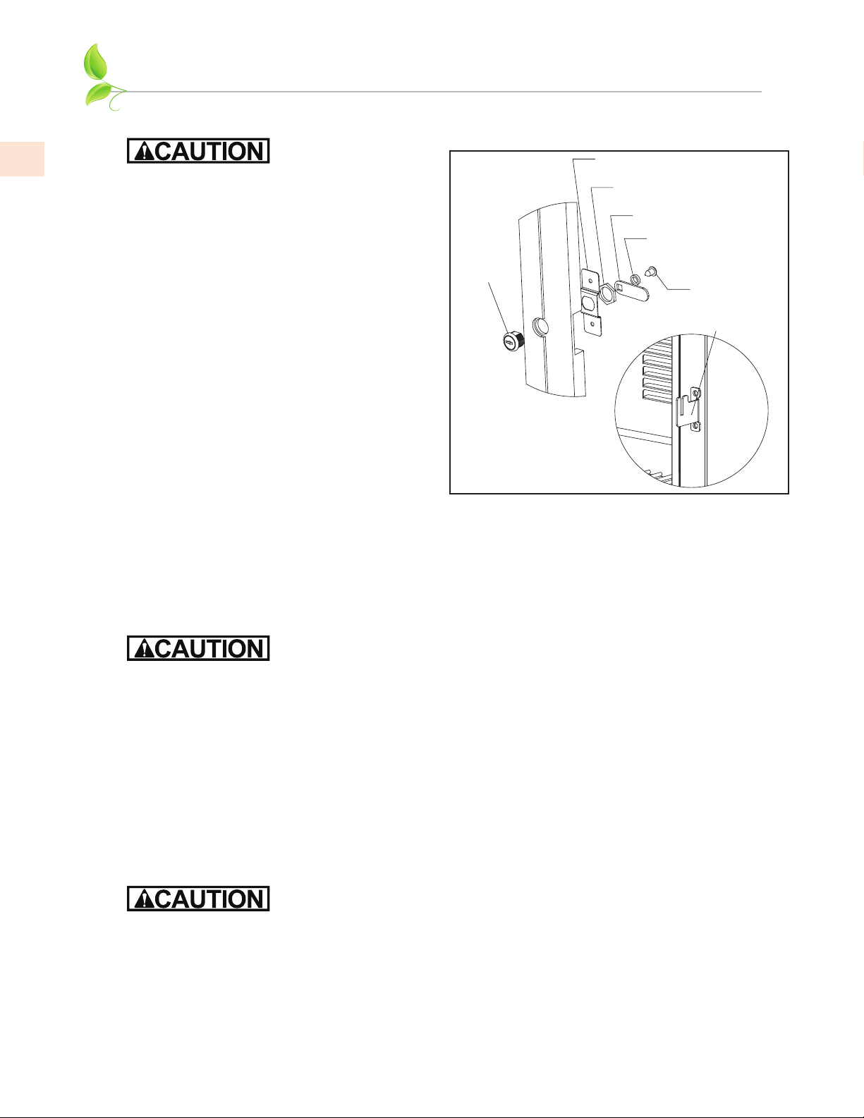
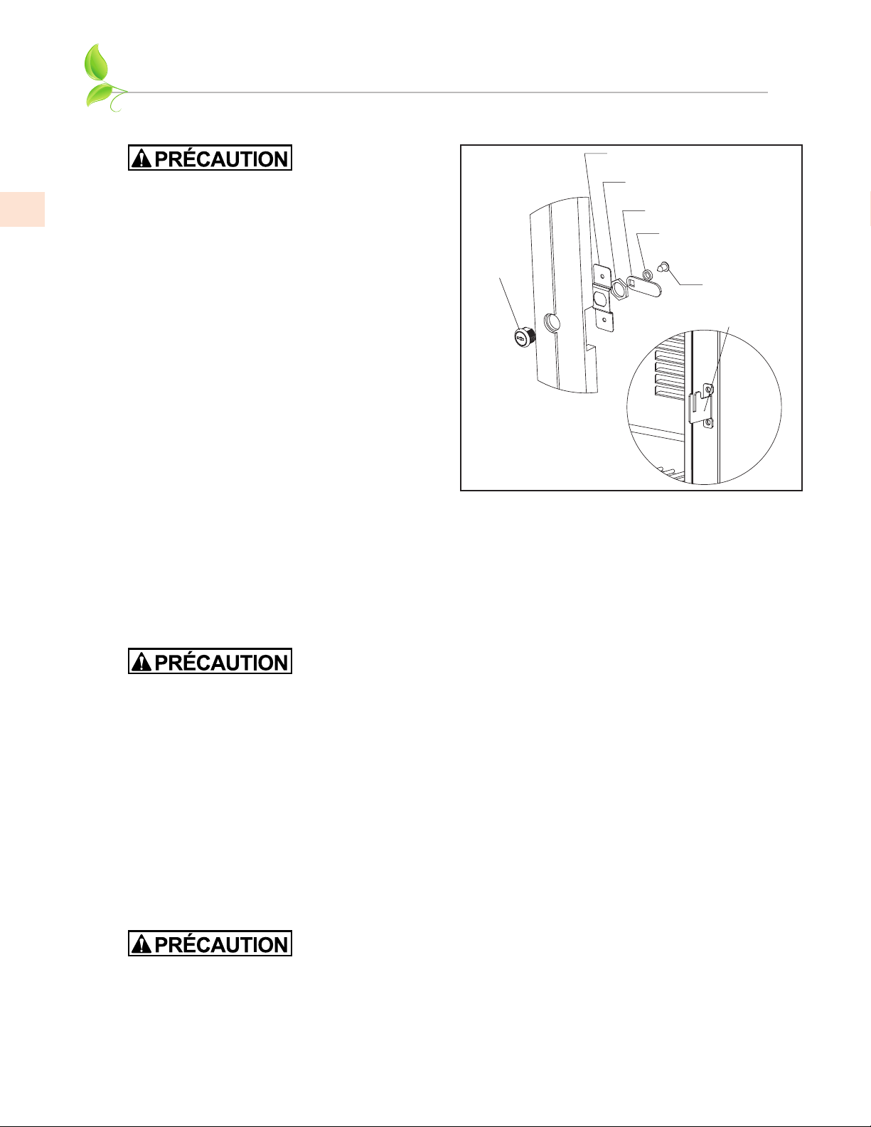
Mounting Bracket
Screw
Lockwasher
Lock Striker
Nut
Lock Bracket
Lock
Cylinder
Figure 5. Installing Door Lock
DOOR LOCK INSTALLATIONDOOR LOCK INSTALLATION
Proper woodworking materials and equipment
should be used to avoid damage or errors in
workmanship.
NOTE: Lock installation information is available
on the above-mentioned template drawings.
Take care in choosing the correct template for
your specific model.
When installing to an overlay panel, perform the
lock installation before mounting the overlay to
the door!
1. See Figure 5. Attach mounting bracket to
overlay panel.
2. Insert lock body and attach with nut. Re-
install remaining parts as shown.
OVERLAY INSTALLATIONOVERLAY INSTALLATION
Before beginning installation, check all components for proper fit and finish.
NOTE: For more detailed installation information, please request or download document 028374
mentioned on the previous page.
For best performance and functionality, the overlay panels should be 3/4” [19
mm] thick. The weight of the overlays should not exceed 20 lbs [9 kg] for
solid doors.
1. With the unit secured in position, open the door, CAREFULLY remove the door gasket (it can
tear), and make sure panel pre-drilled holes align with door frame holes.
2. Loosely attach four corners of overlay panel to the door using #10 x 3/4” wood screws, installed
through the door frame from the rear.
3. Check the overall fit of the overlay panel, position, and function. Make minor adjustments as
necessary. When panel is properly aligned, tighten mounting screws securely. Install the rest of
the mounting screws and tighten securely.
4. Re-install the gasket making sure the dart is securely pressed inside the slot on the door frame.
Start at the four corners and firmly press your way inwards.
5. Verify that the gasket is fully seated onto the door frame when completed.
Do not overtighten overlay panel attachment screws, as this may damage the
factory supplied door frame.
DOOR INFORMATION
(continued)

EN
©2021 Hestan Commercial Corporation
11
INSTALLATION OF DISPENSING EQUIPMENT
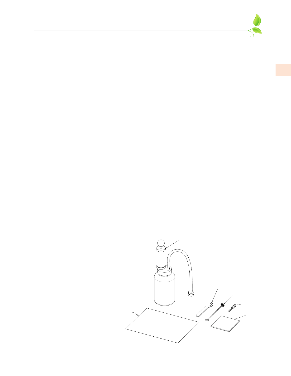
BEFORE INSTALLATIONBEFORE INSTALLATION
Open the tapping kit box and become familiar with its components.
If the dispensing head is going to be mounted on a countertop directly above the refrigerated cabinet,
have the countertop pre-drilled using the printed template in the Appendix of this manual.
Make sure that the access hole in the refrigerated cabinet is in line with the countertop holes.
Remove any obstructions from the access hole of the refrigerator.
FILLING THE COFILLING THE CO
22
CYLINDER CYLINDER
The 5 lb. CO
2
cylinder is not filled. A local welding supply store, locations that fill fire extinguishers,
local home brew shops, and sporting stores that sell paint ball guns are among the most likely places
to get your CO
2
cylinder filled.
ABOUT KEG COUPLERS (TAPS)ABOUT KEG COUPLERS (TAPS)
Your Hestan Beer Refrigerator is supplied with a low-profile coupler for “D” system kegs, commonly
used for beers of the United States and Mexico.
This coupler MUST be used when using Slim 1/4 kegs or 1/6 kegs (23-3/8” [59.4 cm] tall). If you are
using other kegs with A, G, M, S, or U couplers, you must use a standard 1/4 keg (13-7/8” [35.2 cm]
tall) to be able to fit inside the cabinet.
CLEANING THE TAPCLEANING THE TAP
Wash tapping devices thoroughly. Flush beer and faucet lines, as well as the tapping device (keg
coupler) with fresh water.
A beer tap cleaning kit AGDFK is available for purchase separately.
See instructions on the
following pages to properly
install the tapping equipment on
your Hestan unit.
CLEANING JAR
w/ HAND PUMP
SPANNER
WRENCH
FAUCET
BRUSH
CLEANING
CHEMICAL
53g
BALL
LIFTER
INSTRUCTIONS
BEER TAP CLEANING KIT (AGDFK)
EN
©2021 Hestan Commercial Corporation
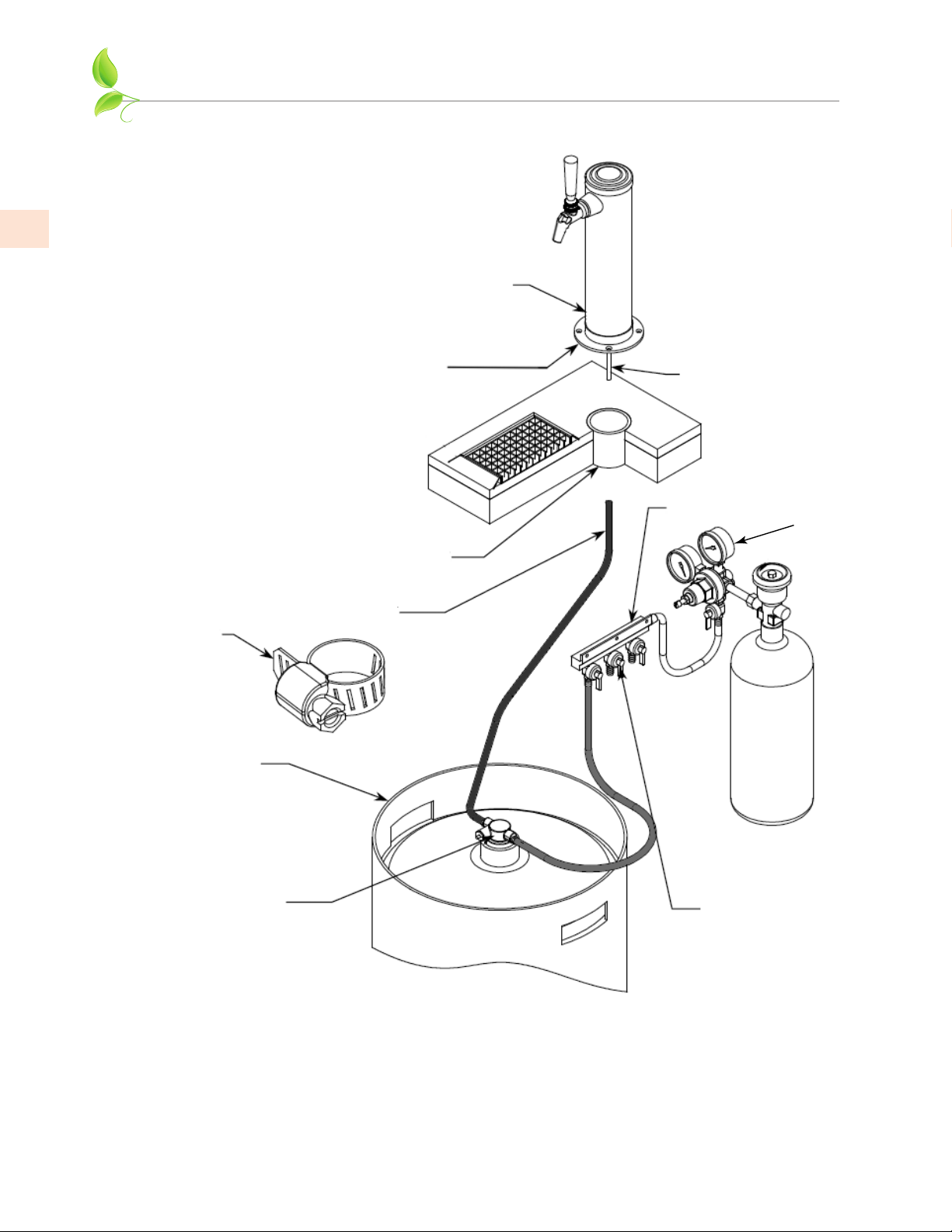
12
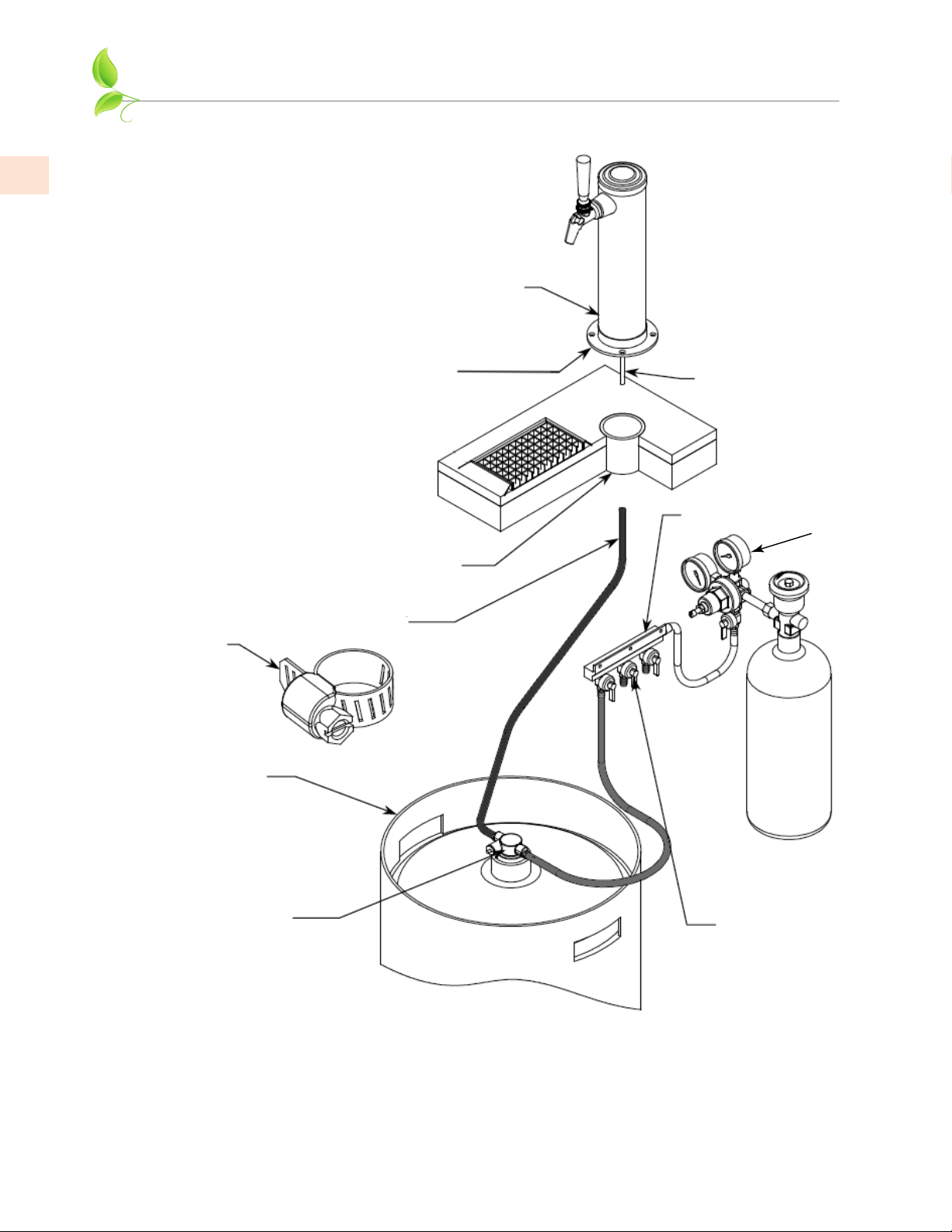
Dispensing Head
Faucet Lead
Apply silicone to
bottom flange
Air Distributor
Flange Sleeve
All hose connections
use worm-drive
hose clamps (view
enlarged to verify)
Distributor is only on
multiple keg units, each
keg is connected to a
valve on the air distributor.
Single keg connected
directly to the regulator.
Keg
Keg Coupler
Beer Connection
NOTE: Image does not accurately reflect positions of the
different elements within the unit. Postions and hose lengths
shown are to clearly illustrate proper connection methods only.
Regulator
INSTALLATION OF DISPENSING EQUIPMENT
(continued)
EN
©2021 Hestan Commercial Corporation
13
INSTALLATION OF DISPENSING EQUIPMENT
(continued)
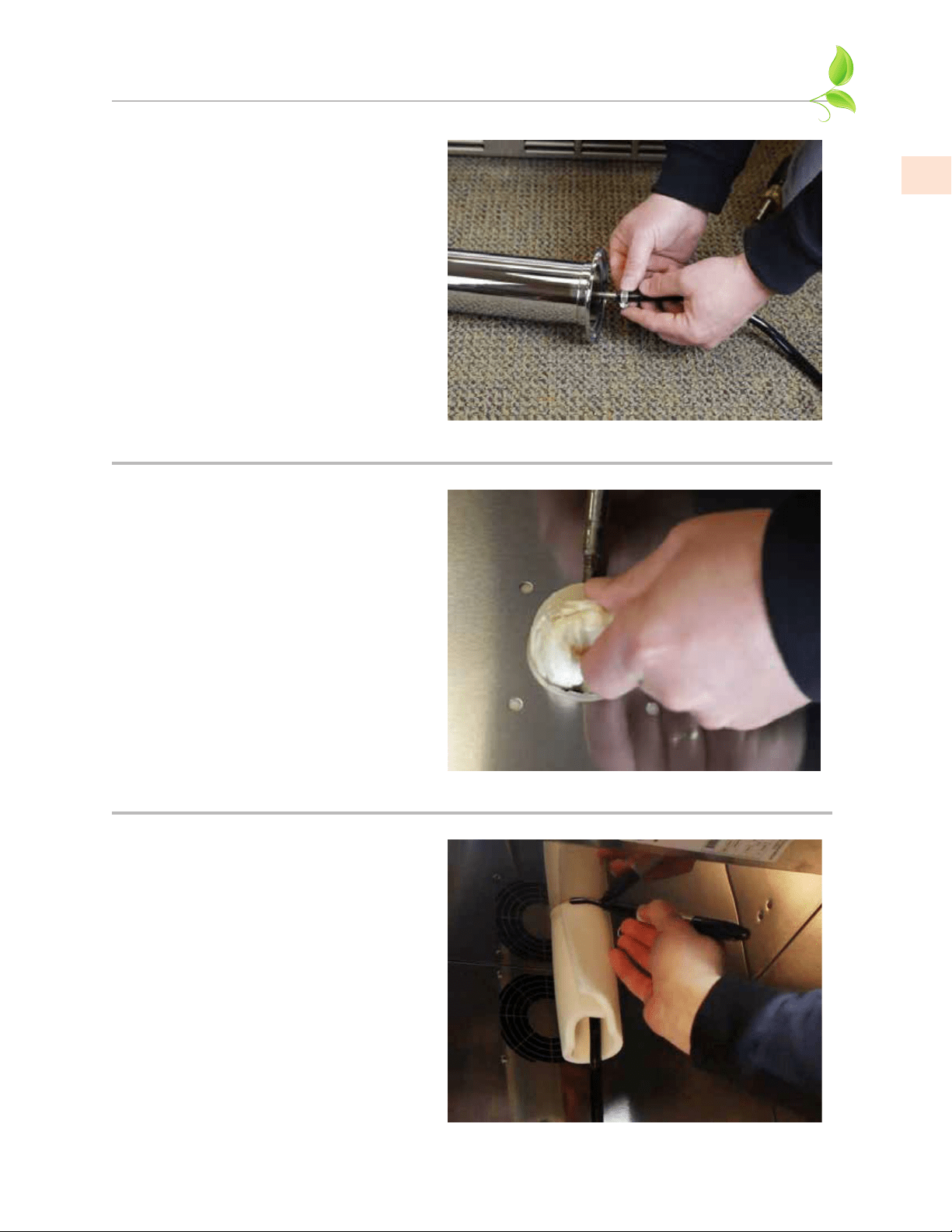
1. Locate the dispensing head , black
beer line(s), and hose clamp(s). Slide
one end of each beer line onto the
stainless steel tubes which protrude
out the bottom of the dispensing head
and clamp tight.
2. Remove transit tape with a utility
knife around the hole in the top of the
unit from both inside and outside of
the cabinet. Gently punch out foam
w/screwdriver and remove. Insert
the beer line(s) through the hole in
the countertop. Move head aside
and apply a bead of silicone around
perimeter of hole, and then position
the head back in place. Fasten using
the 4 chrome screws included with
the dispensing head. Wipe off excess
silicone to complete the seal.
3. Use the 3/8” -thick foam pad included
in the tapping kit and roll into a
cylinder. From inside the cabinet,
insert the foam tube up through the
hole in the countertop until it is firmly
against the insulation in the dispensing
head. Mark, then cut away any excess
foam.
EN
©2021 Hestan Commercial Corporation
14
INSTALLATION OF DISPENSING EQUIPMENT
(continued)
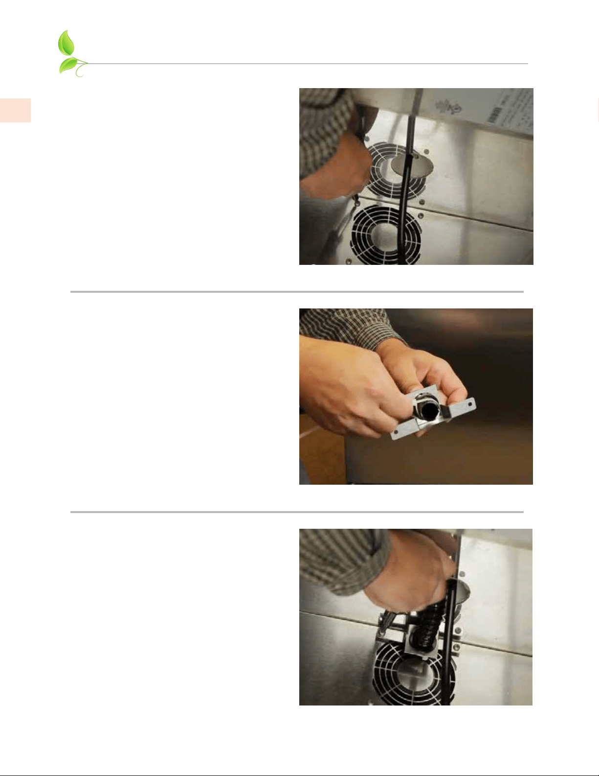
4. Install the Air Scoop Kit. Start by
removing the upper set of screws
located above the fan on the back wall
of the cabinet.
5. Assemble components from the kit as
follows – Insert black snap bushing
into air scoop mounting bracket,
then insert one end of the air snorkel
through the snap bushing. A zip-tie
can be inserted behind the mounting
bracket to keep the tube in place.
6. Insert end of the snorkel up into the
tower and screw air scoop mounting
bracket into vacated holes above the
fan.
EN
©2021 Hestan Commercial Corporation
15
INSTALLATION OF DISPENSING EQUIPMENT
(continued)
7. If installing a two faucet system,
a CO
2
manifold will need to be
installed. Locate the red CO
2
lines,
CO
2
manifold and a #10 x 1/2” sheet
metal screw. Slide one end of each
hose onto the barbed fittings on the
manifold and clamp. On the left rear
side wall of the beer compartment
there is a double row of screws which
run vertically. Remove one of the
two top screws and discard. Insert
the sheet metal screw through the
manifold and into the hole vacated
previously.
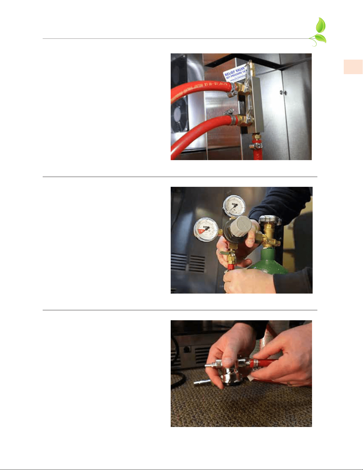
8. On a single beer system, locate the
red CO
2
hose. Slide one end onto the
barbed fitting of regulator assembly
and clamp. On systems with two
beers, locate the CO
2
line that comes
off the backside of the manifold
assembly. Slide the hose onto the
barbed fitting of regulator assembly
and clamp. For detailed information
on connecting the regulator to the
CO
2
cylinder, see page 17.
9. Locate the low profile keg coupler(s).
Slide one of the red CO
2
lines onto
the larger barbed fitting of the keg
coupler and clamp. Locate one of
the black beer lines and slide onto
the smaller barbed fitting of the
keg coupler and clamp. Repeat for
additional couplers.
Note:
See page 11 for info on Keg Couplers.
EN
©2021 Hestan Commercial Corporation
16
INSTALLATION OF DISPENSING EQUIPMENT
(continued)
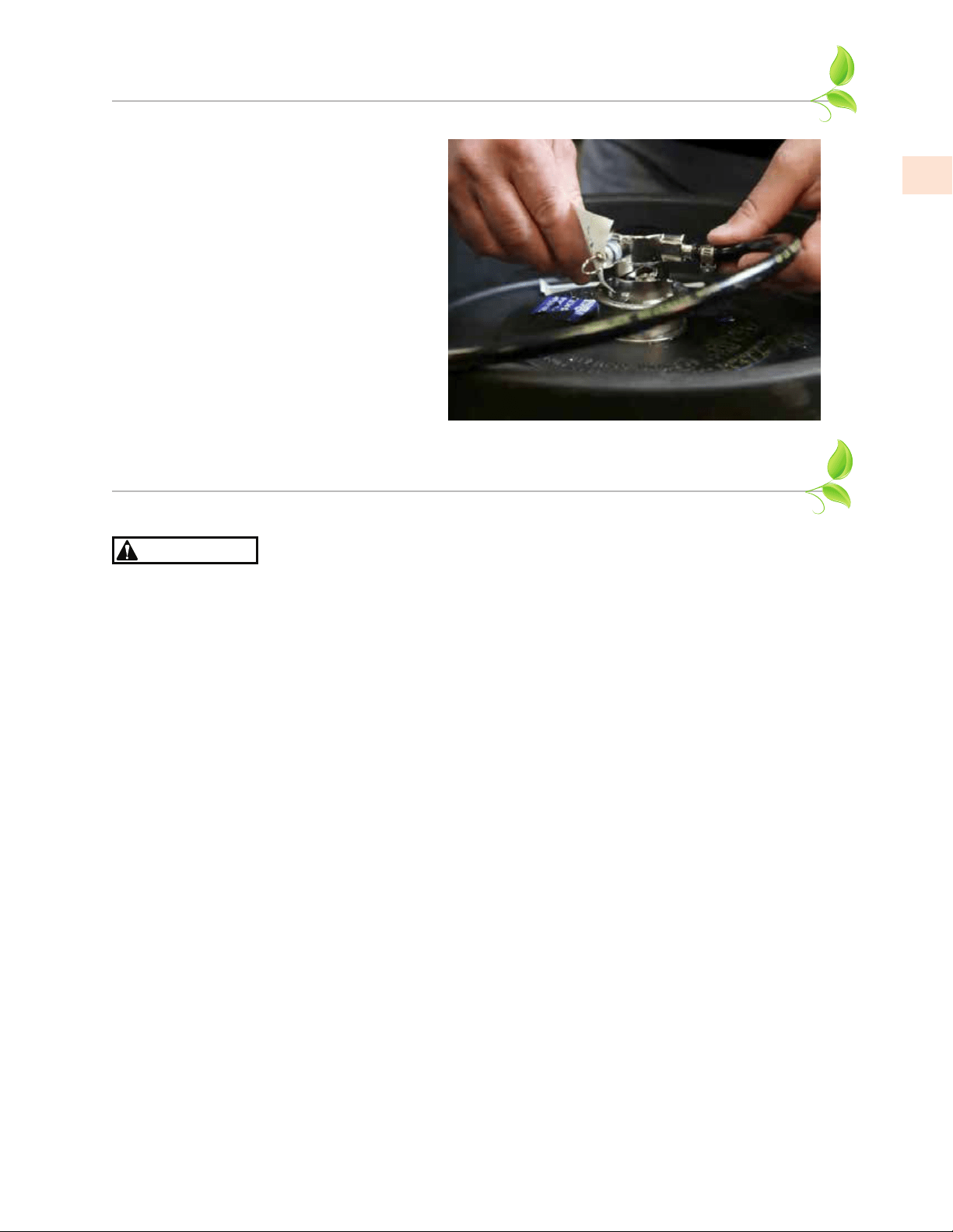
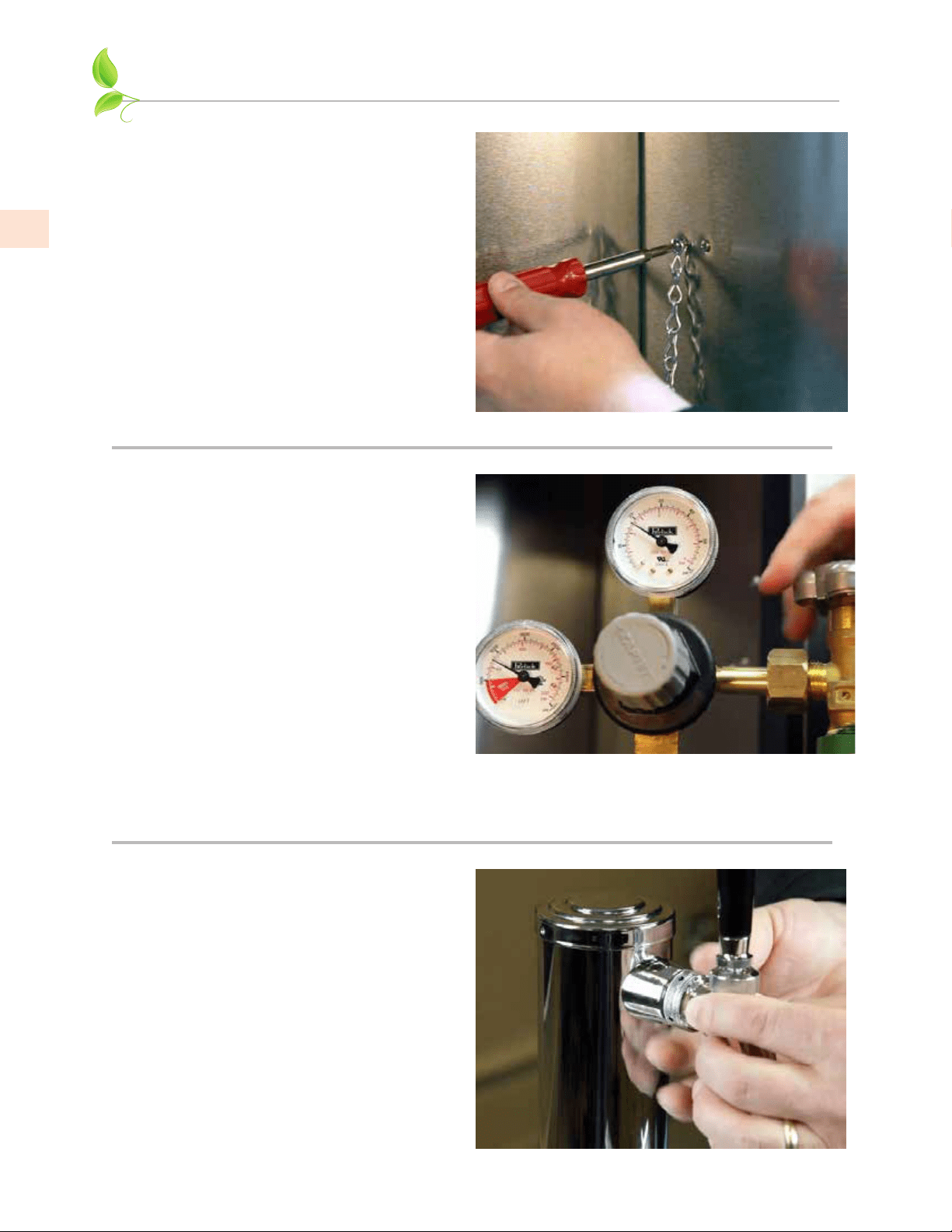
10. On the right rear sidewall there is a
double column of screws. Remove
the left screw. Locate the safety
chain and a #10 x 1/2” sheet metal
screw from the parts bag. Insert the
screw through the closed end link of
the chain and tighten in the vacant
screw hole. The chain can now be
used to secure the CO
2
cylinder with
“S” hook, preventing damage to the
regulator.
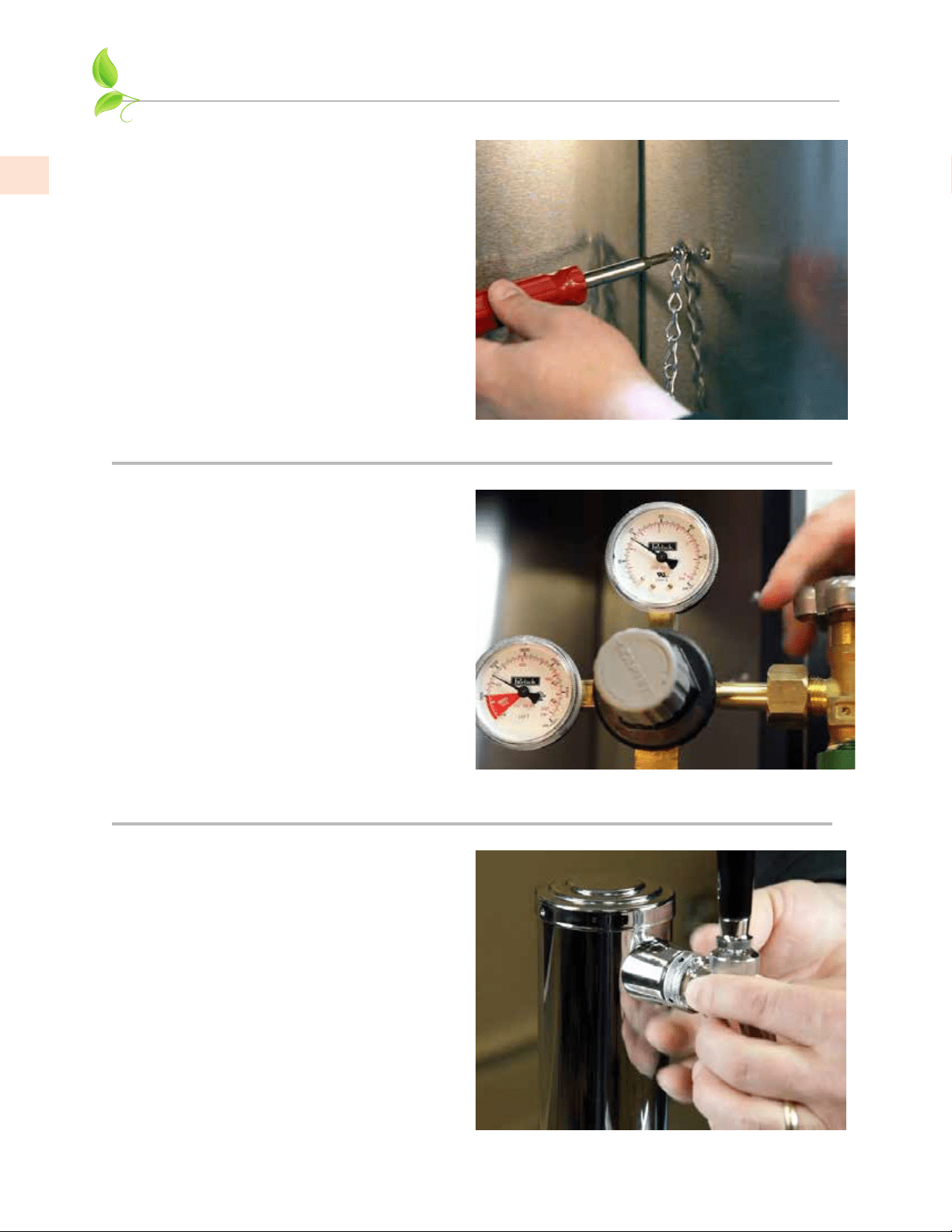
11. CO
2
cylinders are shipped empty
and must be filled prior to use. Turn
the adjusting knob on the regulator
counter-clockwise until the outlet
pressure gauge (top) reads zero. Make
sure that the valve at the bottom of
the regulator where the red hose is
connected, is in the OFF position
as shown on page 18. Watching
the outlet pressure gauge, turn the
regulator adjusting knob clockwise
until the pressure is at 15 psi.
Adjustments can later be made based
on flow rates.
12. Locate the beer faucet(s) and install
onto the dispensing head shanks.
Tighten with supplied spanner wrench.
Install black handle(s) onto faucet(s).
IMPORTANT: All pressure adjustments
MUST be made when the shut-off valve is
in the OFF position!
EN
©2021 Hestan Commercial Corporation
17
INSTALLATION OF DISPENSING EQUIPMENT
(continued)
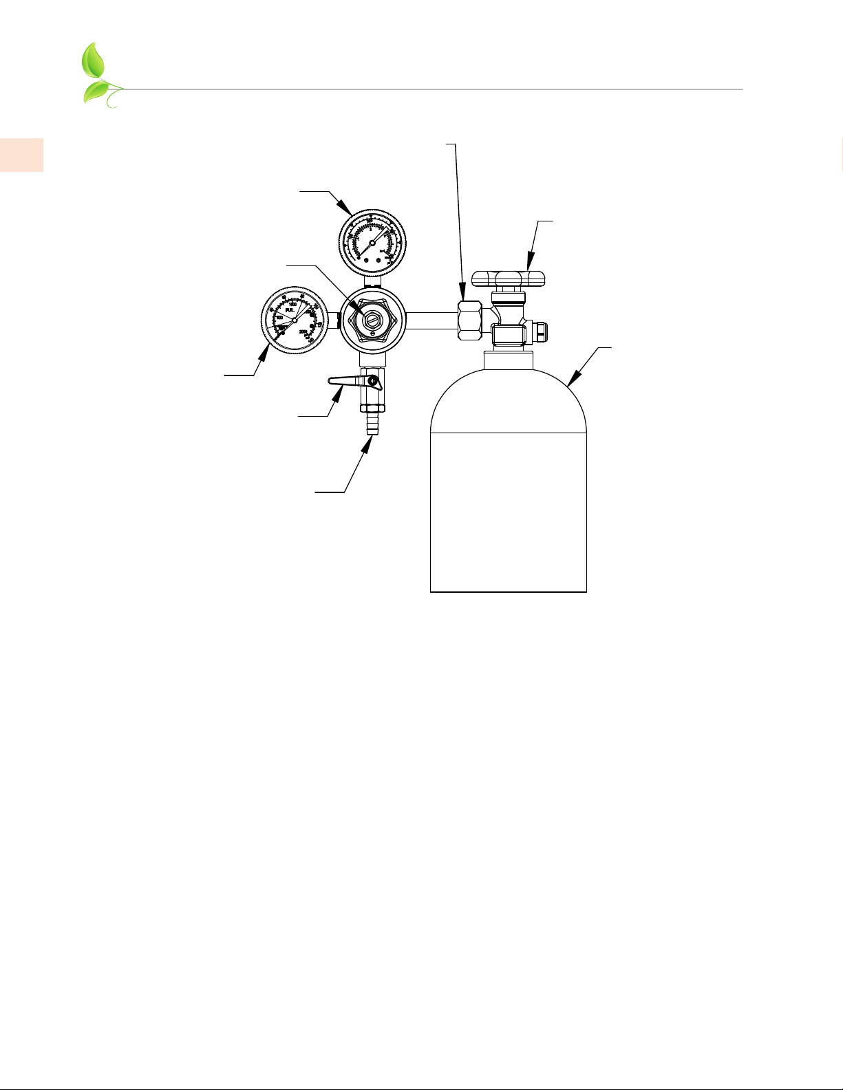
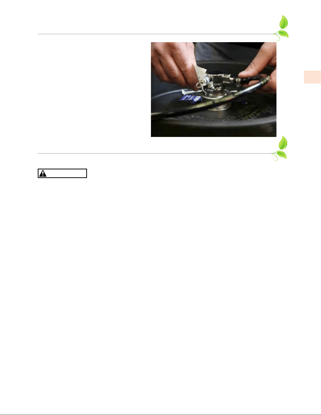
13. Before tapping a keg, make sure the
beer faucet is closed.
To tap a keg, insert the coupler into
the neck of the barrel. Turn the
coupler clockwise until it stops (about
an 1/8 turn), then push down on the
top of the coupler and again turn
clockwise until it stops. Your barrel is
now tapped.
Open the CO
2
valve on the regulator
as well as the valve on the manifold if
used.
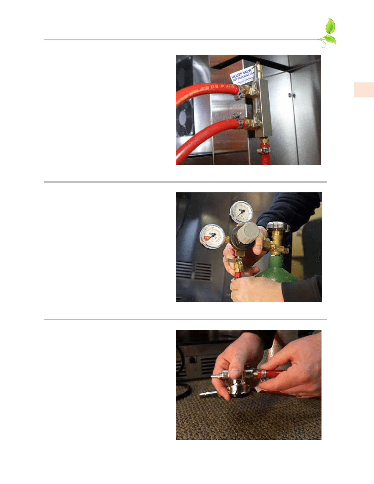
CONNECTING THE REGULATOR TO THE CO
2
CYLINDER
HIGH-PRESSURE GASHIGH-PRESSURE GAS
DANGER
CO
2
cylinders contain high-pressure gas which can be hazardous if not handled properly. Make sure
you READ and UNDERSTAND the following procedures for CO
2
cylinders BEFORE installation.
• ALWAYS connect the CO
2
cylinder to a regulator. Failure to do so could result in an explosion
with possible death or injury when the cylinder valve is opened.
• NEVER connect the CO
2
cylinder directly to the product container (keg). Doing so will result in
an explosion causing possible death or injury.
• ALWAYS follow correct procedures when cylinders are changed.
• ALWAYS secure the cylinder in an upright position with a chain.
• NEVER drop or throw a CO
2
cylinder.
• ALWAYS keep a CO
2
cylinder away from heat. The rupture disc vents at 122°F [50°C] max.
Store extra cylinders in a cool place (preferably 70ºF [21°C]). Securely fasten with a chain in an
upright position when storing. NEVER place cylinders in direct sunlight or where temperature
could rise above 130ºF [54°C].
• ALWAYS ventilate & leave the area immediately if CO
2
gas leakage has occurred. NEVER enter
a closed area where leakage may have occurred.
• ALWAYS check the DOT test date on the cylinder neck before installation. If over five(5) years
old, do not use, return cylinder to gas supplier.
• NEVER connect a product container unless there are two(2) safeties in the pressure system:
(a) one at or on the CO
2
regulator.
(b) one at or on the product coupler or in the pressure gas line.
• CO
2
regulators are delicate instruments and should be checked constantly for creeping,
sluggishness, damaged gauges, or any unusual behavior. If any of these symptoms occur,
discontinue use immediately and return regulator to supplier or manufacturer.
• Allow only properly trained and experienced personnel to handle high-pressure gas.
• Do not apply oil to the regulator!
FAILURE TO CONNECT THE REGULATOR BY PROPERLY FOLLOWING THESE INSTRUCTIONS MAY
RESULT IN LEAKS, EXPLOSIONS, ASPHYXIATION AND CAUSE SERIOUS PERSONAL INJURY OR DEATH.
EN
©2021 Hestan Commercial Corporation
18
CONNECTING THE REGULATOR TO THE CO
2
CYLINDER
(continued)
1. Remove the blue plug from the regulator fitting, but do not remove the carbonic washer.
2. Screw regulator onto gas cylinder valve. Tighten the nut with a wrench until vertically straight.
Be sure that the shut-off valve on the regulator is in the OFF (horizontal) position.
3. Place screw clamp over the end of red air hose and push onto regulator barb fitting. Tighten
clamp with a screwdriver.
4. Turn regulator adjusting knob or screw counter-clockwise until it turns freely.
5. Turn cylinder valve counter-clockwise on the CO
2
cylinder to the fully open position.
6. Turn regulator adjusting knob or screw clockwise until desired pressure is reached (approximately
12-15 psi [83-103 kPa] ). Tighten stop nut on adjusting screw.
7. Open shut-off valve on bottom of regulator.
8. Dilute a small amount of liquid dishwashing soap and rub the soapy mixture around connections.
If bubbles appear, tighten connection.
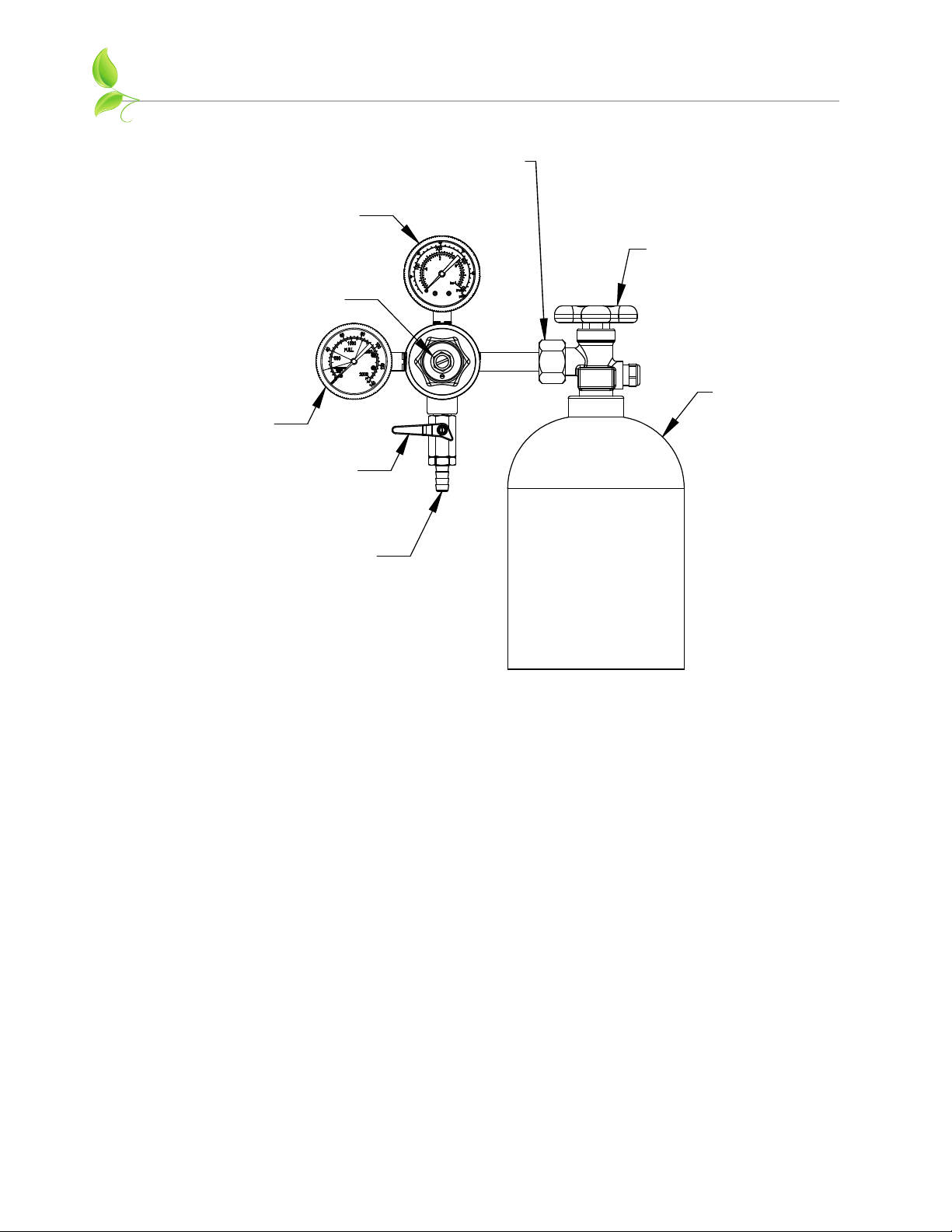
CYLINDER
PRESSURE
REGULATOR
ADJUSTMENT
KNOB OR SCREW
OUTLET
PRESSURE
SHUT-OFF VALVE
OFF POSITION
BARB FITTING FOR
RED AIR HOSE
NUT FOR CO
2
CYLINDER FITTING
CYLINDER
VALVE
CO
2
CYLINDER

EN
©2021 Hestan Commercial Corporation
19
DISPOSAL
DANGER
Risk of child entrapment. Before you throw away your old refrigerator or freezer:
• Take off the door.
• Leave the shelves in place so that children may not easily climb inside.
• Do not allow children to play inside, on, or around the appliance.
Risk of fire or explosion. Please dispose the appliance according to federal or local
regulations for its flammable refrigerant and blowing gas.
NOTES
©2021 Hestan Commercial Corporation
1
FR
1 DÉFINITIONS DE SÉCURITÉ
2 NUMÉROS DE MODÈLE
2 DISPOSITION DES BARILS
3 PLAQUE SIGNALÉTIQUE
3 RESPECT DE LA RÉGLEMENTATION ET DES CODES EN VIGUEUR
3 SÉCURITÉ
5 INSTALLATION DE L’ARMOIRE
8
INFORMATION SUR LA PORTE
10 INSTALLATION DE L’ÉQUIPEMENT DE DISTRIBUTION
16 RACCORDEMENT DU RÉGULATEUR AU CYLINDRE DE CO
2
18
ÉLIMINATION
TABLES DES MATIERES
DÉFINITIONS DE SÉCURITÉ
LISEZ ATTENTIVEMENT ET COMPLÈTEMENT CES INSTRUCTIONS AVANT
D’INSTALLER OU D’UTILISER VOTRE APPAREIL AFIN DE RÉDUIRE LES RISQUES
D’INCENDIE, DE BRÛLURE OU D’AUTRES BLESSURES. CONSERVER CE MANUEL
POUR RÉFÉRENCE FUTURE.
IMPORTANTE! L’installation de l’armoire de distribution de bière réelle doit avoir lieu
avant d’installer l’équipement de distribution. Reportez-vous à la section Installation
du réfrigérateur de ce manuel pour obtenir des instructions pas à pas.
IMPORTANTE! Lisez et comprenez toutes les informations contenues dans ce manuel
avant de tenter l’installation. Tous les travaux de plomberie et d’électricité doivent être
effectués par un technicien qualifié et conformes à tous les codes nationaux et locaux
applicables.
INSTALLATEUR: LAISSER CE MANUEL AVEC LE PROPRIÉTAIRE DE L’APPAREIL.
PROPRIÉTAIRE: CONSERVEZ CE MANUEL POUR RÉFÉRENCE FUTURE.
CELA INDIQUE UN DANGER QUI ENTRAÎNERA DES BLESSURES
GRAVES OU LA MORT SI LES PRÉCAUTIONS NE SONT PAS SUIVIES.
CECI INDIQUE UN DANGER QUI POURRAIT ENTRAÎNER DES
BLESSURES GRAVES OU LA MORT SI LES PRÉCAUTIONS NE SONT
PAS SUIVIES.
CECI INDIQUE UN DANGER LORSQUE DES BLESSURES OU DES
DOMMAGES MATÉRIELS AU PRODUIT OU À LA PROPRIÉTÉ
PEUVENT SURVENIR SI LES PRÉCAUTIONS NE SONT PAS SUIVIES.
CECI INDIQUE QUE DES DOMMAGES MATÉRIELS AU PRODUIT OU
À LA PROPRIÉTÉ PEUVENT SURVENIR SI LES PRÉCAUTIONS NE
SONT PAS SUIVIES.
DANGER
AVIS
DANGER
RISQUE D’INCENDIE OU D’EXPLOSION - RÉFRIGÉRANT INFLAMMABLE
UTILISÉ. Consultez le manuel de réparation / le guide du propriétaire avant
d’essayer de réparer ce produit. Toutes les précautions de sécurité doivent être suivies. À réparer
uniquement par un personnel qualifié. Soyez prudent lors de la manipulation, du déplacement et de
l’utilisation du produit afin d’éviter d’endommager le tube de réfrigérant ou d’augmenter le risque de
fuite.
Tous les travaux d’entretien doivent être exécutés par le personnel de service
autorisé par l’usine et tous les composants doivent être remplacés par des
composants similaires afin de minimiser le risque d’inflammation possible en raison de pièces
incorrectes ou d’un entretien inapproprié.
Si un entretien est nécessaire, les travaux de réparation doivent être
effectués par un réparateur agréé Hestan. Le travail effectué par des
personnes non qualifiées pourrait être potentiellement dangereux et annulera la garantie.
©2021 Hestan Commercial Corporation
2
FR
NUMÉROS DE MODÈLE
No. de Modèle Description
GFDS_241 DISTRIBUTEUR DE BIÈRE SIMPLE INTÉRIEUR / EXTÉRIEUR, PORTE SOLIDE, 24 po
GFDS_241-XX DISTRIBUTEUR DE BIÈRE SIMPLE INTÉRIEUR / EXTÉRIEUR, PORTE SOLIDE, COULEUR, 24 po
GFDS_242 DISTRIBUTEUR DE BIÈRE DOUBLE INTÉRIEUR / EXTÉRIEUR, PORTE SOLIDE, 24 po
GFDS_242-XX DISTRIBUTEUR DE BIÈRE DOUBLE INTÉRIEUR / EXTÉRIEUR, PORTE SOLIDE, COULEUR, 24 po
_ = Modèle à charnière droite (R) ou gauche (L)
Une 1/4 baril
Standard = Ø16-
1
�
8
po x 13-
7
�
8
po H - 7.75 Gal [29.3 l]
Svelte = Ø11-
1
�
8
po x 23-
3
�
8
po H - 7.75 Gal [29.3 l]
Deux 1/6 baril
Ø9-
1
�
4
po x 23-
3
�
8
po H - 5.16 Gal [19.8 l]
DISPOSITION DES BARILS
Les barils de bière standard suivants s’adaptent à l’intérieur de ces unités.
GFDSR241
illustré
GFDSR242
illustré
R600a Refrigerant
DÉFINITIONS DE SÉCURITÉ
(suite)
AVIS
Ce produit contient de la mousse isolante thermique utilisant l’agent gonflant R-611
(Formiate de Méthyle). La mousse de ce produit ne contient pas de HFC, CFC ou HCFC.
Tous les modèles couverts dans ce manuel sont fabriqués à l’aide du réfrigérant R600a (Isobutane).
Le R600a est un hydrocarbure. Ce fluide frigorigène est inflammable et ne doit être utilisé que dans
des appareils qui satisfont aux exigences des normes UL / CEI 60335-1 et UL / CEI 60335-2-24 (pour
couvrir les risques potentiels découlant de l’utilisation de réfrigérants inflammables). Par conséquent,
le R600a ne peut être utilisé que dans les appareils de réfrigération conçus pour ce réfrigérant et
répondant à la norme susmentionnée.
• Le R600a est plus lourd que l’air. La concentration sera toujours la plus élevée au niveau du sol.
• Les limites d’explosion sont les suivantes:
o Limite inférieure: 1,8% en volume
o Limite supérieure: 8,4% en volume
o Température d’inflammation: 860°F [460°C]
©2021 Hestan Commercial Corporation
3
FR
PLAQUE SIGNALÉTIQUE
La plaque signalétique contient des informations importantes sur votre appareil Hestan, telles que
le modèle et le numéro de série, ainsi que des informations sur le réfrigérant si un entretien est
nécessaire.
La plaque signalétique est fixée sur
le dessus intérieur de la caisse.
PLAQUE SIGNALÉTIQUE
RESPECT DE LA RÉGLEMENTATION ET DES CODES EN VIGUEUR
L’installation de cet appareil doit être effectuée conformément aux codes locaux. En l’absence de
tels codes, installer cet appareil conformément au National Electrical Code et les codes locaux.
Tous les composants électriques doivent mis à la terre conformément aux codes locaux ou, en
l’absence de tels codes, au National Electrical Code ANSI/NFPA 70 ou au Code national de
l’électricité du Canada CSA C22.1.
SÉCURITÉ
SÉCURITÉ IMPORTANTE DES ENFANTSSÉCURITÉ IMPORTANTE DES ENFANTS
DANGER
Risque de coincement de l’enfant. Avant de jeter votre
ancien réfrigérateur ou congélateur:
• Enlevez les portes.
• Laissez les étagères en place afin que les enfants ne puissent pas facilement
grimper à l’intérieur.
NE JAMAIS laisser des enfants jouer à l’intérieur de l’appareil.
AVANT L’INSTALLATIONAVANT L’INSTALLATION
Inspectez soigneusement la produit pour détecter tout dommage caché. Si des dommages sont
découverts, déposez votre réclamation immédiatement avec la société de transport. Hestan n’est pas
responsable des dommages en transit. Retirez tous les matériaux d’emballage avant l’utilisation.
DANGER
RISQUE D’INCENDIE OU D’EXPLOSION - RÉFRIGÉRANT INFLAMMABLE
UTILISÉ. Soyez prudent lors de la manipulation, du déplacement et de l’utili-
sation du produit afin d’éviter d’endommager le tube de réfrigérant ou d’augmenter le risque de fuite.
Lorsque vous déplacez l’unité, assurez-vous de protéger le revêtement de sol
fini avec un matériau approprié pour éviter dommages dus au déplacement
de l’appareil. Ne soulevez pas l’unité par le tiroir, les étagères ou les poignées de porte, car cela
pourrait endommager déplacé selon les instructions.
Pour éviter les blessures, au moins deux personnes sont nécessaires pour
soulever l’appareil. Des unités plus grandes peuvent nécessitent du personnel
supplémentaire.
Avant de déplacer l’unité, fermez la porte avec du ruban adhésif pour empêcher la porte de s’ouvrir
pendant qu’elle est déplacée. Déplacez soigneusement l’unité vers le site d’installation et placez-la
devant l’ouverture.
Si l’unité a été posée sur le dos ou sur les côtés, placez-la à la verticale et
attendez au moins 24 heures avant de brancher l’alimentation.
©2021 Hestan Commercial Corporation
4
FR
PLOMBERIEPLOMBERIE
Mis à part les connexions au robinet de bière et au baril (voir page 10), aucune autre connexion de
plomberie n’est requise. Les condensats du serpentin de refroidissement s’évaporent automatiquement
à travers un bac à condensats situé dans la section de condensation de l’unité.
DANGER
GAZ HAUTE PRESSIONGAZ HAUTE PRESSION
• Gardez la cylindre de CO
2
à l’abri de la chaleur. Le disque de rupture est ventilé à 122°F [50°C] max.
• Ne laissez pas tomber ou ne jetez pas le régulateur ou la cylindre de CO
2
.
• Ne laissez que du personnel correctement formé et expérimenté manipuler du gaz à haute pression.
• Ne pas appliquer d’huile sur le régulateur!
DANGER
RISQUE DE CHOC ÉLECTRIQUERISQUE DE CHOC ÉLECTRIQUE
Coupez l’alimentation avant d’installer ou d’entretenir l’appareil. Ne pas le faire peut entraîner la mort
ou un choc électrique.
ALIMENTATION ÉLECTRIQUE ET MISE A LA TERREALIMENTATION ÉLECTRIQUE ET MISE A LA TERRE
• Cet appareil doit être mis à la terre. La mise à la terre réduit le risque de choc
électrique en cas de court-circuit.
• NE PAS mettre à la terre un tuyau de gaz.
• NE PAS utiliser de rallonge avec cet appareil.
• NE PAS avoir de fusible dans le circuit NEUTRE ou MISE À LA TERRE. Un fusible dans le circuit
NEUTRE ou MISE À LA TERRE pourrait provoquer un choc électrique.
ALIMENTATION ÉLECTRIQUEALIMENTATION ÉLECTRIQUE
Un disjoncteur 115 volts CA, 60 Hz, 15 Ampères et une alimentation électrique sont nécessaires. Un
circuit protégé par un disjoncteur de fuite à la terre (GFCI) doit être utilisé lorsqu’il est installé à
l’extérieur.
Cet appareil n’est PAS conçu pour être installé dans des maisons préfabriquées (mobiles) ou des véhicles
récréatifs.
Toutes les unités sont fournies avec un cordon de 5 pieds [1.5 m] avec fiche de mise à la terre à trois
broches. Il est impératif que cette fiche soit connectée à une prise à trois broches correctement mise à
la terre. Si le récipient n’est pas le type de mise à la terre approprié, contactez un électricien. La prise
doit être affleurante ou encastrée dans la surface du mur derrière l’appareil.
• Ne retirez jamais la broche de mise à la terre de cette fiche.
• N’utilisez jamais d’adaptateur à 2 broches.
• Si une prise à 2 broches est rencontrée ou si un cordon d’alimentation plus long est requis,
faites appel à un électricien qualifié pour le faire remplacer conformément aux codes électriques
applicables.
Vérifiez que le cordon électrique et la fiche ne sont pas endommagés avant de
mettre l’appareil sous tension pour éviter tout risque d’électrocution.
AVIS
L’appareil ne doit PAS être totalement enfermé ou des dommages peuvent survenir. La
circulation de l’air ne doit pas être restreinte. Le condenseur à l’avant de l’armoire doit être
doté d’un espace d’air d’au moins 2 po [5 cm]. Assurez-vous de fournir un accès afin que le couvercle
avant puisse être retiré pour nettoyer le condenseur.
N’essayez pas de faire fonctionner l’équipement sur une autre source
d’alimentation que celle indiquée sur la plaque de spécifications électriques
attachée à l’unité.
SÉCURITÉ
(suite)
©2021 Hestan Commercial Corporation
5
FR
DANGER
Ne stockez pas de liquides inflammables (c’est-à-dire d’essence ou de liquide à
briquet) ou de vapeurs à proximité de l’appareil pour éviter un incendie.
INFORMATIONS GÉNÉRALES SUPPLÉMENTAIRES INFORMATIONS GÉNÉRALES SUPPLÉMENTAIRES
Toutes les instructions électriques supposent que la prise est située à 4 - 10 po [10 - 25 cm] au-dessus
de la surface du sol.
Le plancher doit être de niveau dans la zone d’installation. Les niveleurs de pieds sont utilisés
uniquement pour un réglage précis et ne doivent pas être utilisés pour compenser les différences de
sol dépassant 1/2 po [13 mm].
INSTALLATION DE L’ARMOIRE
DANGER
RISQUE D’INCENDIE OU D’EXPLOSION - RÉFRIGÉRANT INFLAMMABLE
UTILISÉ. Soyez prudent lors de la manipulation, du déplacement et de l’utili-
sation du produit afin d’éviter d’endommager le tube de réfrigérant ou d’augmenter le risque de
fuite.
KIT DE ROULETTES (EN OPTION)KIT DE ROULETTES (EN OPTION)
Un kit de roulettes (AGCK24) est disponible pour les modèles de réfrigération Hestan. Reportez-
vous aux instructions fournies avec le kit de roulettes pour une installation correcte.
Remarque: l’installation du kit ajoute 3,75 po [9,5 cm] à la hauteur totale de l’unité.
SUPPORTS ANTI-BASCULEMENTSUPPORTS ANTI-BASCULEMENT
L’unité peut basculer vers l’avant si les racks / étagères chargés sont tous retirés en même temps.
Pour éviter tout basculement et assurer une installation stable, l’unité doit être fixée en place avec
les supports anti-basculement fournis avec l’unité. Les supports anti-basculement, lorsqu’ils sont
correctement installés, devraient fixer les pattes arrière / patins à la surface de montage et empêcher
l’unité de basculer vers l’avant.
AVIS
Les supports anti-basculement ne sont utilisés que pour les armoires fixes et ne doivent
pas être installés sur des armoires avec roulettes accessoires.
En cas d’installation sur un sol en béton, des attaches en béton sont requises et ne sont pas incluses
avec le kit anti-basculement.
Certains sites d’installation peuvent nécessiter des modifications pour fournir une surface sécurisée
pour la fixation des supports.
Un jeu de supports anti-basculement
est fourni avec l’appareil. Ces supports
doivent être fixés au sol à l’arrière de
l’unité. Chaque support doit être situé
pour engager les pieds arrière lorsque
l’armoire est repoussé en position.
Reportez-vous à la figure 1 (illustrée
ci-dessous) pour les emplacements de
montage du support anti-basculement.
15
⁄16 po
3
⁄16 po
22-
3
⁄16 po
Figure 1. Kit Anti-Basculement 24 po
SUPPORTS
SÉCURITÉ
(suite)
©2021 Hestan Commercial Corporation
6
FR
INSTALLATION DE L’ARMOIRE
(suite)
PRÉPARER L’ESPACEPRÉPARER L’ESPACE
Si l’unité doit être installée sous un plan de travail, il est recommandé que le
plan de travail soit soutenu par une structure autre que l’unité elle-même
pour éviter d’endommager l’unité.
Assurez-vous que le plancher sous l’unité est au même niveau que le plancher fini environnant.
Protégez un plancher fini avec du contreplaqué, du carton ou tout autre matériau approprié avant de
déplacer l’unité en place. Le non-respect de cette consigne peut endommager le sol.
Pour assurer des performances maximales, l’air frais doit pouvoir circuler dans le compartiment des
machines. Ne placez rien devant l’appareil qui pourrait obstruer la circulation d’air au niveau de ces
grilles avant. Ne placez pas l’appareil dans une petite pièce non ventilée.
AVIS
L’armoire doit être nivelée de l’avant vers l’arrière, puis d’un côté à l’autre.
1. Assurez-vous que l’ouverture de l’espace est correctement dimensionnée pour l’unité. Voir les
dimensions typiques de l’appareil ci-dessous et le tableau ci-dessous pour les exigences d’ouverture
brute finie:
TAILLE (H) LARGEUR (W) PROFONDEUR (D)
34-3/8 po [87.3 cm] min.
35-1/2 po [90.2 cm] max.
24 po [61 cm] 24 po [61 cm]
24" 611
3
16
" 84
5
12
3
4
" 323
15
1
2
" 394
24
15
16
"
633
16
"
7
214
8
11
15
16
"
303
11" 279
1
5
8
" 42
3
1
2
" 89
21
3
8
" 543
26
9
16
" 674
1
15
16
" 49
87234
5
"*
16
20" 508
14" 356
3
1
2
" 89
21
3
8
" 543
63224
7
8
"
*3
15
16
" 100
606
"
8
7
23
9
16
" 252
15
11
7
8
" 302
18
3
16
" 461
6
5
8
" 168
1
16
" 49
15
6
1
4
" 159
22
1
16
" 560
16
1
8
" 410
MIN. DÉGAGEMENT
POUR PORTE PIVOTANTE
ORIENTATION À 90°
REQUISE POUR LE
DÉGAGEMENT DE
L'ÉTAGÈRE
CORDON D'ALIMEN-
TATION 5 PIEDS
DIMENSIONS DE DÉCOUPE:
34-
3
⁄
8
po H - 24 po W - 24 po D
[873] H - [609] W - [609] D
3-
1
⁄
4
po [83] MIN.
DÉGAGEMENT D'UN
COIN POUR OBTENIR
UNE ORIENTATION À 90°
*
- Les niveleurs de pieds
peuvent ajouter 3/4 po [19] à
ces dimensions lorsqu'ils sont
complètement déployés.
DIMENSIONS TYPIQUES
DE L'APPAREIL
Bac de drainage portable
Tablette incluse avec
les armoires de
distribution.
Convient également à
deux barils de 1/6
lorsque la tablette est
retirée.
1/4 baril typique
©2021 Hestan Commercial Corporation
7
FR
INSTALLATION DE L’ARMOIRE
(suite)
2. Vérifiez que les éléments suivants sont de niveau et d’équerre:
• Ouverture frontale et intérieure
• Ouverture d’installation et surface au sol
• Bord avant inférieur du comptoir
REMARQUE: Pour qu’une porte s’ouvre correctement, la porte doit s’ouvrir d’au moins 90°. Utiliser
un pièce d’obturation d’au moins 3 po [7,6 cm] dans les installations en coin pour assurer une
ouverture complète à 90°. Laisser un dégagement de 25 po [64 cm] à l’avant de l’unité pour une
ouverture complète de la porte et une sortie de tablette / tiroir.
REMARQUE: Le plancher sous l’unité doit être au même niveau que le plancher fini environnant.
Pour éviter d’endommager le comptoir, ne placez pas d’objets lourds sur le
comptoir directement au-dessus de l’appareil.
INSTALLATION DE L’UNITÉ DANS L’ESPACEINSTALLATION DE L’UNITÉ DANS L’ESPACE
1. Branchez l’unité dans la prise électrique mise à la terre de 15 Ampères située dans l’ouverture
d’installation. Une fois l’appareil sous tension, vérifiez que les fonctions d’éclairage et de
refroidissement fonctionnent correctement. Coupez l’alimentation de la prise murale du
disjoncteur.
2. Avec toutes les surfaces dans le carré et le niveau d’ouverture de l’installation, reportez-vous à la
Figure 2 ci-dessous et effectuez les étapes suivantes pour mettre l’unité à niveau:
• À l’avant de l’ouverture, mesurez du plancher jusqu’au bas du bord avant du comptoir.
• Mesurez à partir de la surface du sol jusqu’au sommet de l’unité dans les coins arrière.
• Réglez les pieds de l’unité de sorte que ces deux mesures soient égales. À l’aide d’une clé à
molette ou d’une pince, tournez les pieds dans le sens horaire pour abaisser l’unité, ou dans le
sens anti-horaire pour la soulever.
REMARQUE: Les pieds ne doivent pas dépasser
de plus de 3/4 po [19 mm] du bas de l’unité.
3. Faites glisser l’unité en position dans
l’ouverture. Assurez-vous que les pieds
de mise à niveau arrière glissent sous les
supports anti-basculement fourni. Poussez
l’unité dans l’ouverture jusqu’à ce que le
bord avant inférieur de l’unité affleure les
armoires adjacentes ou jusqu’à ce que les
pieds arrière soient bien serrés contre les
supports anti-basculement.
4. Calez l’avant de l’unité de sorte que la face
avant affleure les armoires adjacentes.
Ajustez les pattes avant pour soutenir le
comptoir à la hauteur calée. À l’aide d’une
clé à molette ou d’une pince, tournez les
pieds dans le sens horaire pour abaisser
l’unité ou dans le sens anti-horaire pour
le relever. Le comptoir doit reposer sur le
dessus de l’unité.
REMARQUE: Le comptoir doit reposer
uniformément sur tout le dessus de l’unité.
Cale si nécessaire pour éviter d’endommager le
comptoir.
5. Vérifiez les ouvertures intérieures des portes
pour vous assurer que l’unité est de niveau et
d’équerre. Installez des étagères.
6. Mettez la prise murale sous tension au
niveau du disjoncteur.
Mesurez l'avant de l'ouverture
de la surface du plancher au
bord inférieur du comptoir.
Mesurez aux deux coins
arrière de l'unité de la surface
du sol au bas du comptoir.
Figure 2. Nivellement de l'unité
©2021 Hestan Commercial Corporation
8
FR
INSTALLATION DE L’ARMOIRE
(suite)
INSTALLATION DU COUVERCLE DE GRILLE AVANTINSTALLATION DU COUVERCLE DE GRILLE AVANT
Une fois l’unité en place, installez le couvercle
de la grille avant à persiennes. Fixez le
couvercle en enclenchant le pêne dans le
loquet de l’unité (Figure 3).
La grille de ventilation doit être retirée pour
l’entretien de l’unité. Le sol ne peut pas
interférer avec l’enlèvement, et les sections
persiennes ne doit pas être couvert ou obstrué.
Des obstructions pourraient empêcher une
bonne circulation de l’air, ce qui pourrait
endommager l’appareil.
REMARQUE: Pour obtenir des performances
maximales, les ouvertures des volets intérieurs
et les ouvertures de protection du ventilateur
ne doivent jamais être obstruées.
Pêne de
Verrouillage
Loquet
Figure 3. Installation de la Grille Avant
INFORMATION SUR LA PORTE
OPTIONS DE PORTEOPTIONS DE PORTE
Les unités résidentielles Hestan peuvent être converties de l’acier inoxydable au des panneaux
de revêtement dans le champ. Les portes solides sont expédiées de l’usine avec des panneaux
en acier inoxydable et des poignées en place sur l’unité. Toutes les portes en acier inoxydable
sont convertibles en modèles entièrement intégrés, prêts à accepter des panneaux personnalisés
(revêtement) de votre fournisseur d’armoires. Vous pouvez contacter le service clientèle de Hestan
pour envoyer l’un des gabarits suivants, ou télécharger directement depuis le Hestan site web à
www.hestanoutdoor.com.
028370 - Gabarit, Revêtement, Porte Solide 24 po, Réfrigération
028371 - Gabarit, Revêtement, Plinthe/Grille 24 po, Réfrigération
028374 - Instructions d’installation, Revêtement, Porte/Tiroir, Réfrigération
Faites attention en choisissant le modèle correct pour votre unité spécifique. La poignée d’appareil
d’origine ou la poignée d’armoire personnalisée peut être installée sur votre panneau de revêtement.
INSTALLATION DE LA POIGNÉEINSTALLATION DE LA POIGNÉE
Le montage de la poignée sur le revêtement en bois doit être monté uniquement sur le revêtement
(pas sur la porte réelle) pour éviter d’endommager la porte d’usine. Des matériaux et équipements
de travail du bois appropriés doivent être utilisés pour éviter des dommages ou des erreurs de
fabrication.
1. La poignée doit être fixée au revêtement avant de le monter sur la porte. Marquez l’arrière du
panneau de revêtement en bois avec les emplacements de fixation de la poignée.
2. Percer le panneau de revêtement en bois aux endroits marqués, en prenant soin de ne pas
endommager le panneau.
3. Utilisez des vis à tête fraisée de sorte que les têtes affleurent le côté arrière du panneau. Fixez la
poignée au panneau de revêtement.
©2021 Hestan Commercial Corporation
9
FR
Support de Montage
Vis
Rondelle de Blocage
Gâche de Serrure
Écrou
Support de Verrouillage
Cylindre de
Serrure
Figure 5. Installation du Verrou de Porte
INSTALLATION DE SERRURE DE PORTINSTALLATION DE SERRURE DE PORT
Des matériaux et équipements de travail du bois
appropriés doivent être utilisés pour éviter des
dommages ou des erreurs de fabrication.
REMARQUE: Les informations d’installation
du verrou sont disponibles sur les dessins de
gabarit mentionnés ci-dessus. Faites attention en
choisissant le modèle correct pour votre modèle
spécifique.
Lors de l’installation sur un revêtement en bois,
effectuez l’installation de la serrure avant de
monter le revêtement en bois sur la porte!
1. Voir la Figure 5. Fixez le support de montage
au revêtement en bois.
2. Insérez le cylindre de verrou et fixez-le avec
l’écrou. Réinstallez les pièces restantes
comme indiqué.
INSTALLATION DU PANNEAU DE REVÊTEMENTINSTALLATION DU PANNEAU DE REVÊTEMENT
Avant de commencer l’installation, vérifiez que tous les composants sont bien ajustés et finis.
REMARQUE: Pour des informations d’installation plus détaillées, veuillez demander ou télécharger le
document 028374 mentionné à la page précédente.
Pour de meilleures performances et fonctionnalités, les panneaux de
revêtement doivent avoir une épaisseur de 3/4 po [19 mm]. Le poids des
revêtements ne doit pas dépasser 20 lb [9 kg] pour les portes solides, 10 lb [4,5 kg] pour les portes
vitrées ou 10 lb [4,5 kg] pour les modèles à tiroirs.
1. Une fois l’unité en place, ouvrez la porte, retirez ATTENTIVEMENT le joint de la porte (il peut se
déchirer) et assurez-vous que les trous pré-percés du panneau sont alignés avec les trous du cadre
de la porte.
2. Fixez sans serrer les quatre coins du panneau de revêtement à la porte à l’aide de vis à bois n° 10 x
3/4 po, installées à travers le cadre de la porte par l’arrière.
3. Vérifiez l’ajustement, la position et la fonction globale du panneau de revêtement. Faites des
ajustements mineurs si nécessaire. Lorsque le panneau est correctement aligné, serrez fermement
les vis de montage. Installez le reste des vis de montage et serrez fermement.
4. Réinstallez le joint en vous assurant que la fléchette est fermement enfoncée dans la fente du
cadre de la porte. Commencez par les quatre coins et appuyez fermement vers l’intérieur.
5. Vérifiez que le joint est bien en place sur le cadre de la porte une fois terminé.
Ne serrez pas trop les vis de fixation du panneau de revêtement en bois, car
cela pourrait endommager le cadre de porte fourni en usine.
INFORMATION SUR LA PORTE
(suite)
©2021 Hestan Commercial Corporation
10
FR
INSTALLATION DE L’ÉQUIPEMENT DE DISTRIBUTION
AVANT L’INSTALLATIONAVANT L’INSTALLATION
Ouvrez la boîte du kit de distribution et familiarisez-vous avec ses composants.
Si la tête de distribution doit être montée sur un plan de travail directement au-dessus de l’armoire
réfrigérée, faites percer le plan de travail en utilisant le modèle imprimé dans l’annexe de ce manuel.
Assurez-vous que le trou d’accès dans l’armoire réfrigérée est aligné avec les trous du comptoir.
Retirez tout obstacle du trou d’accès du réfrigérateur.
REMPLISSAGE DU CYLINDRE COREMPLISSAGE DU CYLINDRE CO
22
La cylindre de CO
2
de 5 livres n’est pas préremplie. Un magasin de fournitures de soudage local, des
emplacements qui remplissent des extincteurs, des magasins de brasseries locales et des magasins
de sport qui vendent des pistolets à peinture sont parmi les endroits les plus susceptibles de remplir
votre cylindre de CO
2
.
À PROPOS DES COUPLEURS DE BARILÀ PROPOS DES COUPLEURS DE BARIL
Votre réfrigérateur à bière Hestan est fourni avec un coupleur à profil bas pour les barils du système
«D», couramment utilisé pour les bières des États-Unis et du Mexique.
Cet coupleur DOIVENT être utilisés lors de l’utilisation de barils minces 1/4 ou 1/6 (23-3/8 po [59,4
cm] de hauteur). Si vous utilisez d’autres barils avec des coupleurs du système A, G, M, S ou U,
vous devez utiliser un baril standard 1/4 (13-7/8 po [35,2 cm] de hauteur) pour pouvoir s’adapter à
l’intérieur de l’armoire.
NETTOYAGE DU DISTRIBUTEURNETTOYAGE DU DISTRIBUTEUR
Laver soigneusement les composants du distributeur. Rincer les conduites de bière et de robinet, ainsi
que le coupleur de baril avec de l’eau fraîche.
Un kit de nettoyage pour robinet de bière AGDFK est disponible à l’achat séparément.
Consultez les instructions des
pages suivantes pour installer
correctement l’équipement
de distribution sur votre unité
Hestan.
POT DE NETTOYAGE
AVEC POMPE À MAIN
CLÉ
BROSSE DE
ROBINET
NETTOYAGE
CHIMIQUE
53g
LEVE-
BOULE
INSTRUCTIONS
KIT DE NETTOYAGE DU ROBINET À BIÈRE (AGDFK)
©2021 Hestan Commercial Corporation
11
FR
Tête de distribution
Fil de robinet
Appliquer du
silicone sur la
bride inférieure
Distributeur d'air
Manchon à bride
Tous les raccords de
tuyaux utilisent des
colliers de serrage à
vis sans fin (vue
agrandie pour vérifier)
Le distributeur est uniquement
sur plusieurs unités de baril,
chaque baril est connecté à
une vanne sur le distributeur
d'air. Baril simple connecté
directement au régulateur.ment
au régulateur.
Baril
Coupleur de
valve de baril.
Connexion de bière
REMARQUE: l'image ne reflète pas avec précision les positions du
différents éléments au sein de l'unité. Les positions et les longueurs
de tuyau illustrées sont pour illustrer clairement uniquement les
méthodes de connexion appropriées.
Regulateur
INSTALLATION DE L’ÉQUIPEMENT DE DISTRIBUTION
(suite)

©2021 Hestan Commercial Corporation
12
FR
INSTALLATION DE L’ÉQUIPEMENT DE DISTRIBUTION
(suite)
1. Localisez la tête de distribution, les
conduites de bière noire et les colliers
de serrage. Faites glisser une extrémité
de chaque ligne de bière sur les tubes
en acier inoxydable qui dépassent le
bas de la tête de distribution et serrez
fermement.
2. Retirez le ruban de transport avec
un couteau utilitaire autour du trou
dans le haut de l’unité de l’intérieur
et de l’extérieur de l’armoire. Percez
doucement la mousse avec un
tournevis et retirez-la. Insérez les
conduites de bière dans le trou du
comptoir. Déplacez la tête de côté et
appliquez un cordon de silicone autour
du périmètre du trou, puis remettez
la tête en place. Fixez à l’aide des 4
vis chromées fournies avec la tête
de distribution. Essuyez l’excès de
silicone pour compléter le joint.
3. Utilisez le coussin en mousse de 3/8
po d’épaisseur inclus dans le kit et
roulez dans un cylindre. De l’intérieur
de l’armoire, insérez le tube en mousse
à travers le trou dans le comptoir
jusqu’à ce qu’il soit fermement contre
l’isolation dans la tête de distribution.
Marquez, puis coupez tout excès de
mousse.

©2021 Hestan Commercial Corporation
13
FR
INSTALLATION DE L’ÉQUIPEMENT DE DISTRIBUTION
(suite)
4. Installez le kit prise d’air. Commencez
par retirer le jeu de vis supérieur situé
au-dessus du ventilateur sur la paroi
arrière de l’armoire.
5. Assemblez les composants du kit
comme suit - Insérez la bague de
pression noire dans le support de
montage de la prise d’air, puis insérez
une extrémité du tuba à air à travers
la bague de pression. Un serre-câble
peut être inséré derrière le support
de montage pour maintenir le tube en
place.
6. Insérez l’extrémité du tuba dans la tour
et vissez le support de montage de la
prise d’air dans les trous libres au-
dessus du ventilateur.
©2021 Hestan Commercial Corporation
14
FR
INSTALLATION DE L’ÉQUIPEMENT DE DISTRIBUTION
(suite)
7. Si vous installez un système à deux
robinets, un collecteur de CO
2
devra
être installé. Localisez les lignes de
CO
2
rouges, le collecteur de CO
2
et
une vis à tôle #10 x 1/2 po. Faites
glisser une extrémité de chaque tuyau
sur les raccords cannelés du collecteur
et fixez-les. Sur la paroi latérale
arrière gauche du compartiment à
bière se trouve une double colonne de
vis qui sont montées verticalement.
Retirez l’une des deux vis supérieures
et jetez-la. Insérez la vis à tôle dans
le collecteur et dans le trou laissé
précédemment.
8. Sur un système à bière unique,
repérez le tuyau de CO
2
rouge. Faites
glisser une extrémité sur le raccord
cannelé du régulateur et fixez-
le. Sur les systèmes à deux bières,
localisez la conduite de CO
2
qui
se détache à l’arrière du collecteur.
Faites glisser le tuyau sur le raccord
cannelé du régulateur et fixez-le.
Pour des informations détaillées sur
le raccordement du régulateur à la
cylindre CO
2
, voir page 16.
9. Localisez le coupleur de baril à profil
bas. Faites glisser l’une des lignes
rouges de CO
2
sur le plus grand
raccord cannelé du coupleur et fixez-
le. Localisez l’une des conduites de
bière noire et glissez-la sur le petit
raccord cannelé du coupleur et fixez-
le. Répétez l’opération pour les
coupleurs supplémentaires.
Remarque:
Voir page 10 pour plus d’informations sur
les coupleurs de baril.
©2021 Hestan Commercial Corporation
15
FR
INSTALLATION DE L’ÉQUIPEMENT DE DISTRIBUTION
(suite)
10. Sur la paroi latérale arrière droite se
trouve une double colonne de vis.
Retirez la vis gauche. Localisez la
chaîne de sécurité et une vis à tôle #10
x 1/2 po du sac de pièces. Insérez la vis
à travers le maillon d’extrémité fermé
de la chaîne et serrez dans le trou de
vis vide. La chaîne peut maintenant
être utilisée pour fixer la cylindre de
CO
2
avec un crochet en «S», ce qui
évite d’endommager le régulateur.
11. Les cylindres CO
2
sont expédiées
vides et doivent être remplies avant
utilisation. Tournez le bouton de
réglage du régulateur dans le sens anti-
horaire jusqu’à ce que le indicateur de
pression de sortie (en haut) indique
zéro. Assurez-vous que la robinet au
bas du régulateur où le tuyau rouge
est connecté, est en position OFF
(Arrêt) comme illustré à la page 17. En
regardant le indicateur de pression de
sortie, tournez le bouton de réglage
du régulateur dans le sens horaire
jusqu’à ce que la pression soit à 15 psi.
Des ajustements peuvent ensuite être
effectués en fonction des débits.
12. Localisez le(s) robinet(s) de bière et
installez-le sur la tête de distribution.
Serrez avec la clé fournie. Installez les
poignées noires sur les robinets.
IMPORTANT: Tous les réglages de
pression DOIVENT être effectués lorsque
la vanne d’arrêt est en position OFF.
©2021 Hestan Commercial Corporation
16
FR
INSTALLATION DE L’ÉQUIPEMENT DE DISTRIBUTION
(suite)
13. Avant de percer un baril, assurez-vous
que le robinet de bière est fermé.
Pour percer un baril, insérez le
coupleur dans le col du baril. Tournez
le coupleur dans le sens anti-horaire
jusqu’à ce qu’il s’arrête (environ 1/8
de tour), puis appuyez sur le haut du
coupleur et tournez à nouveau dans
le sens anti-horaire jusqu’à ce qu’il
s’arrête. Votre baril est maintenant
percé.
Ouvrez la robinet de CO
2
sur le
régulateur ainsi que la robinet sur le
collecteur si utilisé.
RACCORDEMENT DU RÉGULATEUR AU CYLINDRE DE CO
2
GAZ HAUTE PRESSIONGAZ HAUTE PRESSION
DANGER
Les cylindres de CO
2
contiennent du gaz à haute pression qui peut être dangereux s’il n’est pas manipulé
correctement. Assurez-vous de LIRE et COMPRENDRE les procédures suivantes pour les cylindres de
CO
2
AVANT l’installation.
• TOUJOURS connecter la cylindre de CO
2
à un régulateur. Ne pas le faire pourrait entraîner une
explosion avec la mort ou des blessures possibles lorsque la soupape de la cylindre est ouverte.
• NE JAMAIS connecter la cylindre de CO
2
directement au conteneur de produit (baril). Cela
entraînera une explosion pouvant entraîner la mort ou des blessures.
• TOUJOURS suivre les procédures correctes lorsque les cylindres sont changés.
• TOUJOURS fixer le cylindre en position verticale avec une chaîne.
• NE JAMAIS laisser tomber ou jeter une cylindre de CO
2
.
• TOUJOURS garder une cylindre de CO
2
à l’abri de la chaleur. Le disque de rupture est ventilé à
122°F [50°C] max.
• Conserver les cylindres supplémentaires dans un endroit frais (de préférence 70°F [21°C]). Fixez
solidement avec une chaîne dans un position verticale lors du stockage. NE JAMAIS placer les
cylindres à la lumière directe du soleil ou à un endroit où la température pourrait dépasser 130°F
[54°C].
• TOUJOURS aérer et quitter immédiatement la zone en cas de fuite de CO
2
. NE JAMAIS entrer une
zone fermée où une fuite peut s’être produite.
• TOUJOURS vérifier la date du test DOT sur le col du cylindre avant l’installation. Si plus de cinq (5)
ans vieux, ne pas utiliser, retourner la cylindre au fournisseur de gaz.
• NE JAMAIS connecter un contenant de produit à moins qu’il n’y ait deux (2) sécurités dans le
système de pression:
(a) un sur ou sur le régulateur de CO
2
.
(b) un sur ou sur le coupleur de produit ou dans la conduite de gaz sous pression.
• Les régulateurs de CO
2
sont des instruments délicats et doivent être contrôlés en permanence pour
lenteur, jauges endommagées ou tout comportement inhabituel. Si l’un de ces symptômes se produit,
arrêtez immédiatement l’utilisation et renvoyez le régulateur au fournisseur ou au fabricant.
• Ne laissez que du personnel correctement formé et expérimenté manipuler du gaz à haute pression.
• Ne pas appliquer d’huile sur le régulateur!
NE PAS CONNECTER LE RÉGULATEUR EN SUIVANT CORRECTEMENT CES INSTRUCTIONS
PEUT RÉSULTER EN FUITES, EXPLOSIONS, ASPHYXIATION ET CAUSER DES BLESSURES
GRAVES OU LA MORT.
©2021 Hestan Commercial Corporation
17
FR
RACCORDEMENT DU RÉGULATEUR AU CYLINDRE DE CO
2
(suite)
1. Retirez le bouchon bleu du raccord du régulateur, mais ne retirez pas la rondelle carbonique.
2. Visser le régulateur sur la valve de la cylindre de gaz. Serrez l’écrou avec une clé jusqu’à ce qu’il
soit verticalement droit. Assurez-vous que la robinet d’arrêt du régulateur est en position OFF
(horizontale).
3. Placer le collier de serrage sur l’extrémité du tuyau d’air rouge et pousser sur le raccord cannelé
du régulateur. Serrez la collier avec un tournevis.
4. Tournez le bouton de réglage du régulateur ou vissez-le dans le sens anti-horaire jusqu’à ce qu’il
tourne librement.
5. Tournez le robinet de la cylindre dans le sens anti-horaire sur la cylindre de CO
2
en position
complètement ouverte.
6. Tourner le bouton de réglage du régulateur ou la vis dans le sens horaire jusqu’à ce que la pression
souhaitée soit atteinte (environ 12-15 psi [83-103 kPa]). Serrez l’écrou d’arrêt sur la vis de réglage.
7. Ouvrez la robinet d’arrêt au bas du régulateur.
8. Diluez une petite quantité de savon à vaisselle liquide et frottez le mélange savonneux autour des
connexions. Si des bulles apparaissent, resserrez la connexion.
PRESSION DU
RÉSERVOIR
BOUTON OU VIS
DE RÉGLAGE DU
RÉGULATEUR
PRESSION
DE SORTIE
POSITION D'ARRÊT DE
LA VANNE D'ARRÊT
RACCORD CANNELÉ
POUR TUYAU D'AIR
ROUGE
ECROU POUR
RACCORD DE
RESERVOIR CO
2
ROBINET DE
RÉSERVOIR
RÉSERVOIR
CO
2

©2021 Hestan Commercial Corporation
18
FR
ÉLIMINATION
DANGER
Risque de coincement de l’enfant. Avant de jeter votre ancien réfrigérateur:
• Enlevez les portes.
• Laissez les étagères en place afn que les enfants ne puissent pas facilement
grimper à l’intérieur.
• Ne laissez pas les enfants jouer dans, sur ou autour de l’appareil.
Risque d’incendie ou d’explosion. Veuillez éliminer l’appareil conformément aux réglementations
fédérales ou locales pour son réfrigérant inflammable et son gaz de soufflage.
NOTES

©2021 Hestan Commercial Corporation
19
FR
THIS PAGE LEFT INTENTIONALLY BLANK
CETTE PAGE EST INTENTIONNELLEMENT VIDE
©2021 Hestan Commercial Corporation
20
FR
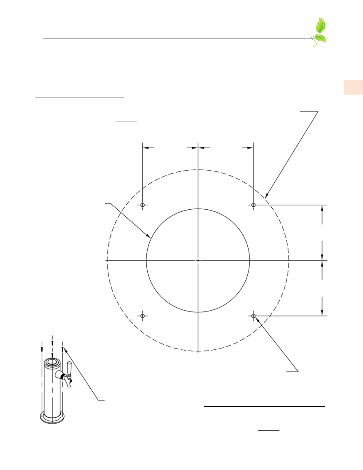
APPENDIX / ANNEXE
MOUNTING HOLE TEMPLATE
FOR DRAFT ARMS
GABARIT DE TROU DE MONTAGE
POUR TÊTE DE DISTRIBUTEUR
ATTENTION AUX INSTALLATEURS
CECI EST UN GABARIT DE GRANDE TAILLE.
VEUILLEZ CONFIRMER QUE LES DIMENSIONS
SONT À L'ÉCHELLE AVANT L'INSTALLATION.
4-1/2” DIAM.
STANDARD FAUCET BASE
(BASE DE ROBINET STANDARD)
2-9/16” DIAM.
HOLE (TROU)
1-3/8” 1-3/8”
1-3/8”
1-3/8”
3/32” DIAM. HOLE (TROU)
(4) REQ.
#8 X 1-1/4” LONG
SCREWS (VIS)
(4) REQ.
ATTENTION INSTALLERS
THIS IS A FULL SIZE TEMPLATE.
PLEASE CONFIRM THAT DRAWING
DIMENSIONS ARE TO SCALE PRIOR
TO INSTALLATION.

Hestan Commercial Corporation
3375 E. La Palma Ave.
Anaheim, CA 92806
(888) 905-7463
RETAIN THIS MANUAL FOR FUTURE REFERENCE
CONSERVEZ CE MANUEL POUR UNE RÉFÉRENCE FUTURE
©2021 Hestan Commercial Corporation P/N 011028 REV C