Service Documentation
Service Manual No. 01/2008 LHG/TKD-Ne/23.10.08
Page 1/21 01200800SM_gb.doc
After Sales Service International
Appliance Documentation
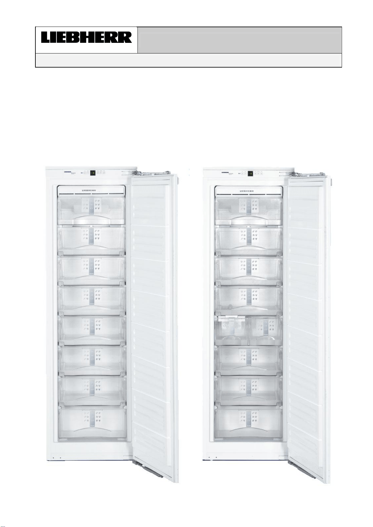
IGN 2556 from Index 20
IGN 2566 from Index 20
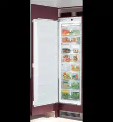
with IceMaker
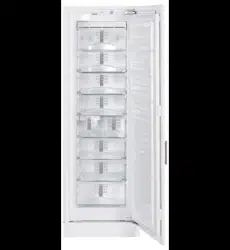
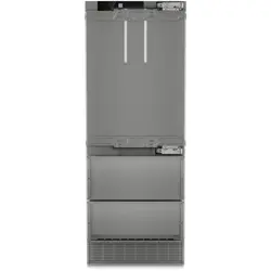
NoFrost freestanding freezer
IGN 2556
IGN 2566

Service Information No. 01/2008 IGN 2556/2566
Page 2/21
Contents
1.0 Operating and control elements...............................................................................................3
2.0 Functions at a glance ................................................................................................................3
3.0 Description of appliance ...........................................................................................................4
3.1 Sensor positions, schematic diagrams 4
4.0 Main components and their functions .....................................................................................5
4.1 Electrical components and functions 5
4.1.1 General 5
4.1.2 Freezer compartment 5
4.2 Refrigeration components and functions 8
4.2.1 Freezer compartment 8
5.0 Assembly instructions / replacement of parts ........................................................................9
5.1 General 9
5.1.1 Electronic control system 9
5.1.2 Door magnet 10
5.2 Freezer compartment 11
5.2.1 Evaporator module 11
5.2.2 Evaporator sensor 12
5.2.3 Air sensor 12
5.2.4 Fan 13
5.2.5 Temperature fuse 14
5.2.6 IGN 2566 only, IceMaker 15
5.2.7 IGN 2566 only, double solenoid valve IceMaker 15
6.0 Technical data..........................................................................................................................16
6.1 General 16
6.2 Freezer compartment 16
7.0 Service menu............................................................................................................................17
7.1 Manual defrosting 17
7.2 Demo mode 17
7.3 Service mode 18
7.4 Sensor test (temperature display) and door contact test "E" 19
8.0 Error code, troubleshooting....................................................................................................19
8.1 Table of error codes 19
8.2 Troubleshooting VCC compressor / inverter 20
8.2.1 Checking the inverter and the frequency signal 20
8.2.2 Checking the compressor 21
Service Information No. 01/2008 IGN 2556/2566
Page 3/21
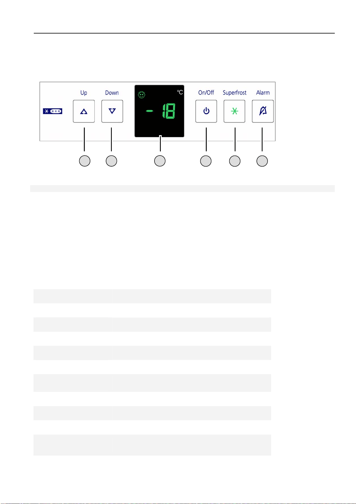
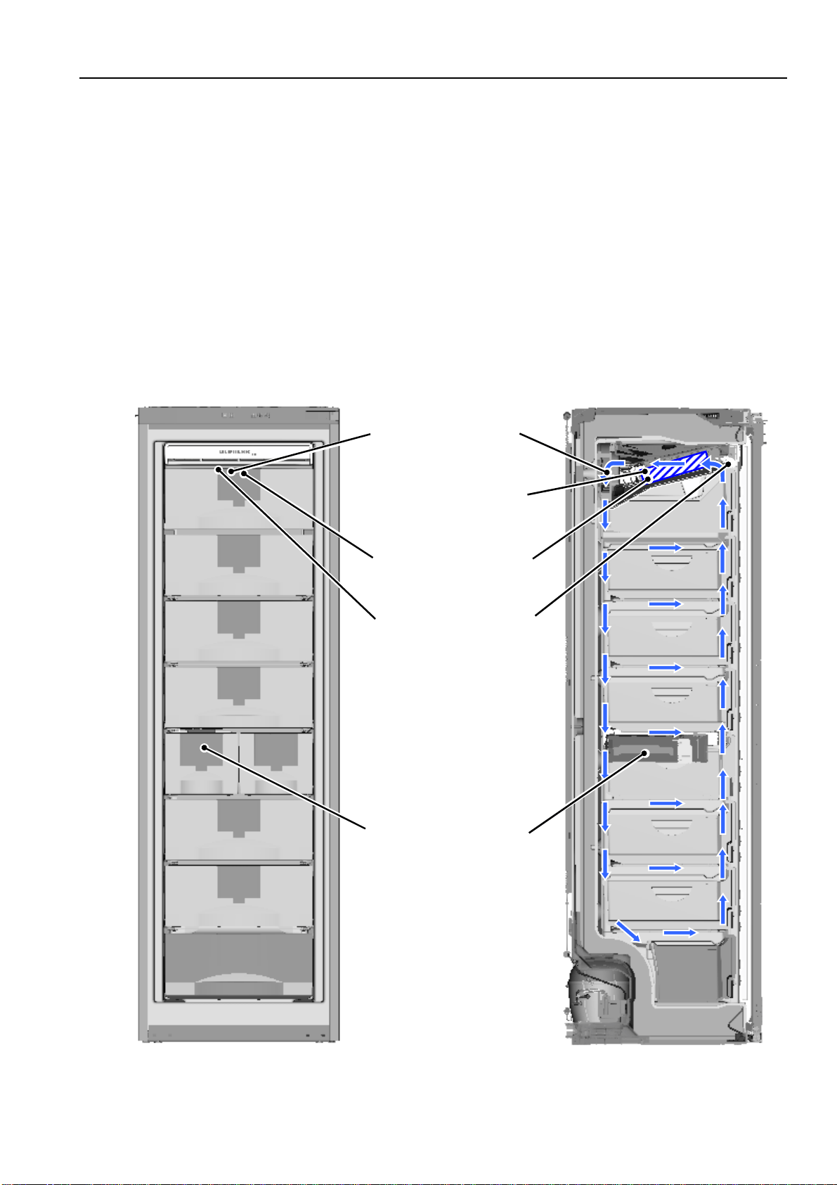
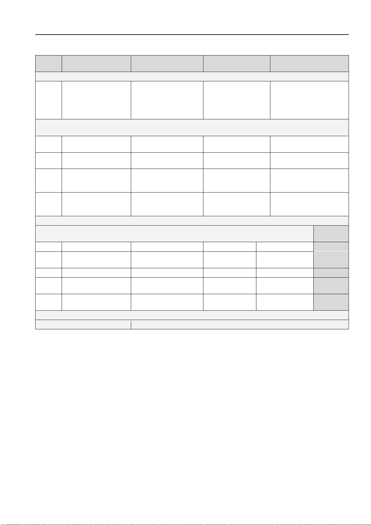
1.0 Operating and control elements
Freezer compartment
1 Up Setting button temperature higher
2 Down Setting button temperature lower
3 Temperature/function display
4 ON/OFF ON/OFF button
5 SuperFrost SuperFrost function
6 Alarm Alarm OFF button for audible alarm
2.0 Functions at a glance
Control:
Electronic
Temperature display:
Actual value
Temperature range:
-14°C to -28°C
Temperature alarm:
Visual, audible
Door alarm:
Audible
Fan:
Present
Defrosting:
Automatic
Interior light:
Present
Service menu:
Present
Compressor:
VCC
Solenoid valve
refrigeration circuit:
Not present
1
2
3
4
5
6
Service Information No. 01/2008 IGN 2556/2566
Page 4/21
3.0 Description of appliance
The IGN 2556/2566 is a NoFrost freezer using a series 6 control system with actual value display.
The appliance has a lamellar evaporator with fan and integrated defrost heater. Two sensors, an air sensor and
an evaporator sensor, see to the control and automatic defrosting. A safety temperature limiter protects the
appliance against excessively high temperatures during the defrosting phase.
The IGN 2566 is equipped with an IceMaker.
3.1 Sensor positions, schematic diagrams
Fig. 3.1 / 2 Fig. 3.1 / 1
Fan
Foamed-in rear wall
evaporato
r
Evaporator sensor
Air sensor
IGN 2566 only:
IceMaker

Service Information No. 01/2008 IGN 2556/2566
Page 5/21
4.0 Main components and their functions
4.1 Electrical components and functions
4.1.1 General
Electronic control system
Type:
Series 6 electronic control system
Components:
Electronic single-board solution
4.1.2 Freezer compartment
Electronic control system
Setting range:
-14°C to -28°C
Display range:
0°C to -49°C
Values outside the range are indicated by a cross bar
Functions
Temperature alarm:
Alarm value: 4K warmer than set value.
Warmest alarm value: -10 °C
Coldest alarm value: -20 °C
Delay: 20 minutes
Visual: Flashing alarm LED
Audible: 4 beeps (suppressed during start-up)
During start-up: The temperature display flashes until the switch-off
value is reached, the audible alarm is switched OFF.
(e.g. given a set value of -18°C, a temperature of –14°C must be present for at
least 20 minutes, then a temperature alarm is raised.)
When the defrosting phase begins, the temperature alarm is suppressed for
1.5 hrs.
Defrosting:
ON: - During start-up after 6 hours cumulative compressor
running time.
- After a cumulative compressor running time of 10 to 30 hours
maximum, depending on the number/duration of the door
openings.
When the defrosting phase begins, the compressor and the fan are
switched OFF and the defrost heater is switched ON.
Duration: The defrost heater remains switched ON until
- the freezer compartment evaporator sensor has reached +32°C
or
- a max. defrosting time of 50 minutes has been reached.
Info: After the end of the heating phase the compressor is switched ON
with a 15-minute delay. Fan ON, from -25°C.
If the SuperFrost function is activated during the defrosting phase,
this will not interrupt defrosting.
Door alarm:
When: If door is open, after 60 seconds.
Audible: 3 beeps.
Service Information No. 01/2008 IGN 2556/2566
Page 6/21
SuperFrost:
ON: Freezer compartment sets itself to -32°C (quantity-controlled, min.
30 hrs., max. 65 hrs.)
The appliance sets itself to -32°C for at least 30 hours. In the
following 35 hours cooling by 11K to the set value must have been
reached or a total time of 65 hours must have elapsed in order that
SuperFrost is automatically ended.
OFF: The freezer compartment sets itself to the set value.
Note: If SuperFrost is actuated during a defrosting phase, the SuperFrost
function is not performed before the defrosting phase has run.
Sensor
Air sensor:
Position: Behind the front panel of the evaporator module.
Function: - Switches the compressor ON/OFF.
- Generates the display value.
Evaporator sensor:
Position: Slipped into the lamellar evaporator.
Function: - Switches the defrost heater OFF (ends the defrosting phase).
- Switches the fan ON/OFF.
Switch
Door switch:
Position: In front panel
Type: Reed contact
Contact type: Make contact
Function: Activation via:
magnet on the door, magnet is replaceable.
Switching signal when:
door open: fan OFF
door alarm ON after 60 seconds
Loads
Fan:
Position: In the evaporator module, at the back centre.
Function:
Switch-on value evaporator sensor:
a) During start-up/after defrosting: -25°C
b) In the normal mode 2K colder than air sensor
Evaporator
sensor
Compressor Door Fan
Switch-on
value
OFF CLOSED
OFF
Switch-on
value
ON CLOSED
ON
Switch-on
value
OFF/ON OPEN
OFF
Switch-off
value
OFF/ON
CLOSED/
OPEN
OFF
e.g. If the evaporator sensor has reached the switch-on value for the fan and the
compressor is ON and the door is CLOSED, then the fan is ON.

Service Information No. 01/2008 IGN 2556/2566
Page 7/21
Defrost heater:
Position: Clipped into lamellar evaporator
Function: Keeps the evaporator free from ice. Activation via electronic control
system.
Defrost heater ON:
- Depending on the number and duration of door openings, the
electronic system calculates the defrost cycles between 10-30
hours cumulative compressor running time.
- Upon start-up after 6 hours cumulative
compressor running time.
Defrost heater OFF:
- When the evaporator sensor has reached +32°C
- When max. time of 50 minutes is exceeded.
Heater cannot be replaced Æonly complete evaporator module!
Compressor:
Type: VCC compressor, frequency-controlled.
Function: ON: Air sensor switch-on value
Note: On-delay time (8 minutes) must have elapsed.
OFF: Air sensor switch-off value.
VCC compressor, frequency-controlled.
• Compressor with 4 different speeds (1600 / 1900 / 3000 / 3600 rpm).
• The inverter electronic control is fitted directly on the compressor. The inverter
electronic control controls the compressor with a pulse-width modulated
square-wave voltage.
• For speed value input, the inverter electronic module receives a square wave
frequency signal from the power PCB.
This frequency signal is output with 56, 71, 87,100 or 117 Hz, depending on
the speed at which the compressor is to run.
Frequency in Hz Speed in rpm Operation
56 Compressor OFF Compressor OFF
71 1600 Ideal case
87 1900 Control mode
100,
0 (signal interruption),
other values than the
defined frequencies
3000
Start-up, signal
interruption, signal fault
117 3600 SuperFrost
• Runtime longer than 70 minutes:
Speed increase by one step during compressor operation.
• Runtime shorter than 40 minutes:
Speed reduction on next start-up.
For troubleshooting, see section 8.2 Troubleshooting VCC compressor / inverter

Service Information No. 01/2008 IGN 2556/2566
Page 8/21
4.2 Refrigeration components and functions
4.2.1 Freezer compartment
Compressor
Compressor:
VCC, frequency-controlled
Frame heater
Position:
Foamed-in in the housing, in the contact area of the magnetic door seal.
Evaporator
Type:
Lamellar evaporator.
Type of installation:
In evaporator module on appliance ceiling
Injection point:
Front centre
Flow sequence:
Front to back
Service Information No. 01/2008 IGN 2556/2566
Page 9/21
5.0 Assembly instructions / replacement of parts
5.1 General
5.1.1 Electronic control system
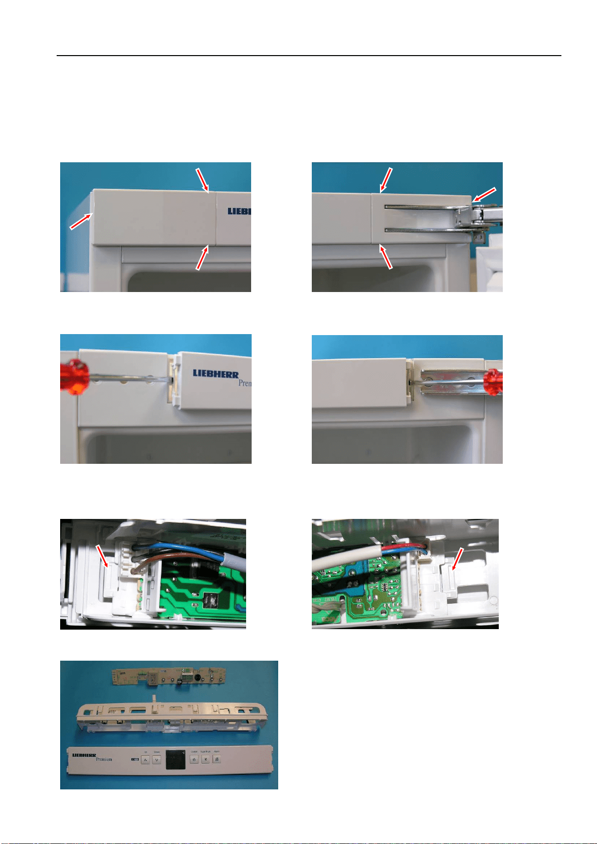
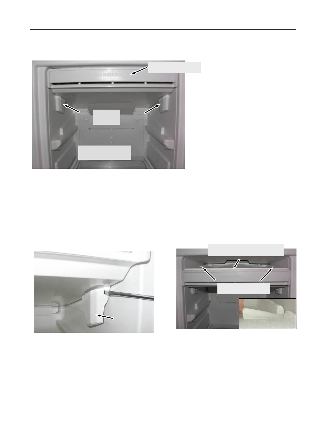
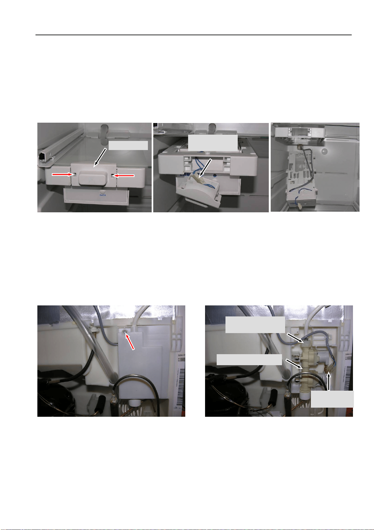
Covers: Disengage covers at the marked points.
Front panel: Unlock locating lugs at the left and right of the front panel.
PCB carrier: Draw the front panel forwards for removal and expose the cables.
Disconnect and detach group connectors.
Fig. 5.1.1/ 1 Left cover Fig. 5.1.1/ 2 Right cover
Fig. 5.1.1/ 3 Left locating lug Fig. 5.1.1/ 4 Right locating lug
Fig. 5.1.1/ 5 Group connector
Fig. 5.1.1/ 6 Group connector
Fig. 5.1.1/ 7 Front panel assembly
Service Information No. 01/2008 IGN 2556/2566
Page 10/21
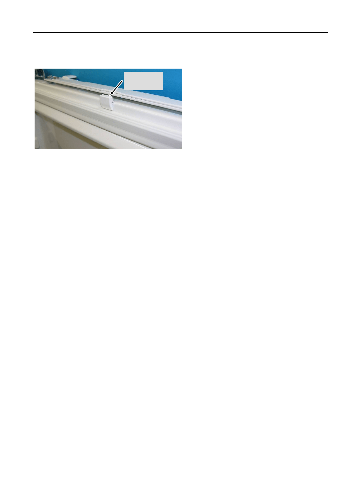
5.1.2 Door magnet
Magnet holder: Press marked locating lugs together and detach magnet holder upwardly.
Fi
g
. 5.1.2 / 1
Magnet
holder
Service Information No. 01/2008 IGN 2556/2566
Page 11/21
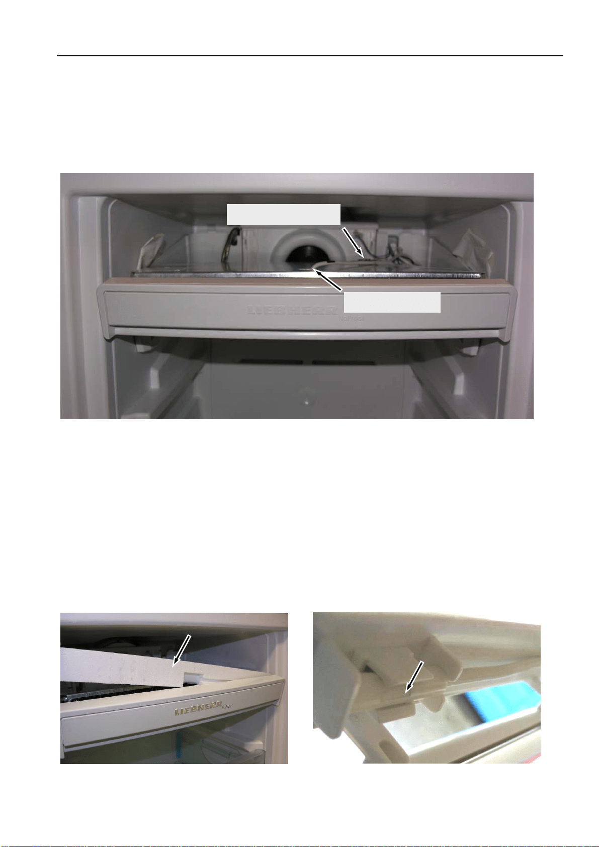
5.2 Freezer compartment
5.2.1 Evaporator module
Locking parts: Are snapped into place at the right and left for locking the evaporator module.
Transit support: Remove the adhesive tape as transit support of the "top polystyrene moulding", it is no
longer needed for assembly (Fig. 5.2.1/ 3).
Top polystyrene moulding: Lift off the polystyrene moulding first at the front, then at the back.
Draw the "top polystyrene moulding" forwards for removal.
Fi
g
. 5.2.1/ 2 Remove lockin
g
p
art
Fi
g
. 5.2.1/ 1 Eva
p
orator module
Locking
parts
Remove top drawers
Evaporator module
Fi
g
. 5.2.1/ 3 Remove adhesive ta
p
e
Top polystyrene moulding
Adhesive tape
Service Information No. 01/2008 IGN 2556/2566
Page 12/21
5.2.2 Evaporator sensor
Evaporator module: Dismantle the evaporator module as described below under 5.2.1 Evaporator
module.
Evaporator sensor: Is slipped inbetween the lamellas and in case of defect it has to be cut off and
repaired with the repair kit (Art. No. 9590 062).
5.2.3 Air sensor
Evaporator module: Dismantle the evaporator module as described below under 5.2.1 Evaporator
module.
Front polystyrene moulding: Is situated behind the front panel is the evaporator module (is only inserted).
Acts as an air seal of the air sensor in the direction of the lamellar evaporator.
Air sensor: Is engaged behind the front panel of the evaporator module and in case of defect
it has to be cut off and repaired with the repair kit (Art. No. 9590 062).
Fi
g
. 5.2.3/ 1 Removal of the
p
ol
y
st
y
rene
Fi
g
. 5.2.3/ 2
A
ir sensor
Fig. 5.2.2/ 1 Evaporator module folded down
Evaporator
Temperature fuse
Service Information No. 01/2008 IGN 2556/2566
Page 13/21
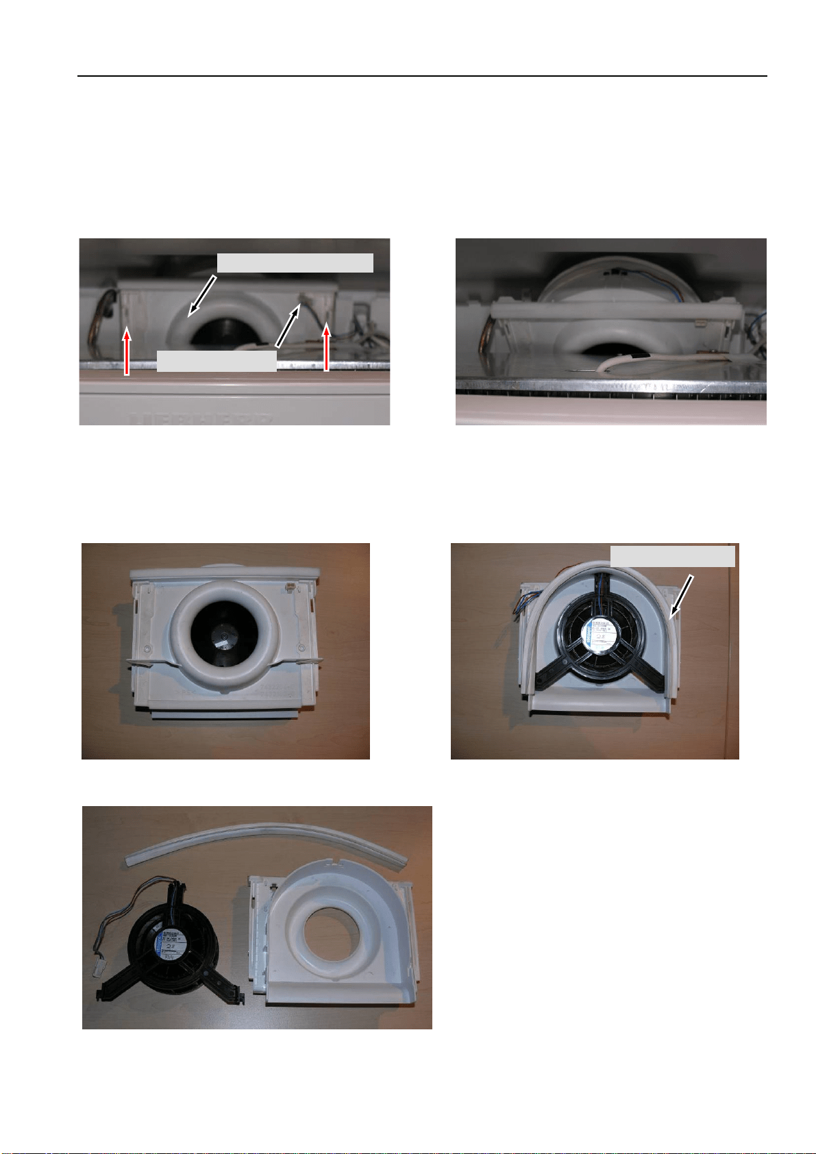
5.2.4 Fan
Evaporator module: Dismantle the evaporator module as described below under 5.2.1 Evaporator
module.
Fan casing: Detach fan connector. Lift the fan casing out of the housing support, swing it down
and remove it.
Fan: Lay the fan casing front face down, and remove the attached sealing rubber at the
rear. Detach the fan from the housing.
Fig. 5.2.4/ 2 Fan casing, swung down
Fan casing
Fig. 5.2.4/ 1 Fan casing
Fan connector
Fig. 5.2.4/ 3 Fan housing, front face
Sealing rubber
Fig. 5.2.4/ 4 Fan housing, rear
Fig. 5.2.4/ 5 Fan housing, components
Service Information No. 01/2008 IGN 2556/2566
Page 14/21
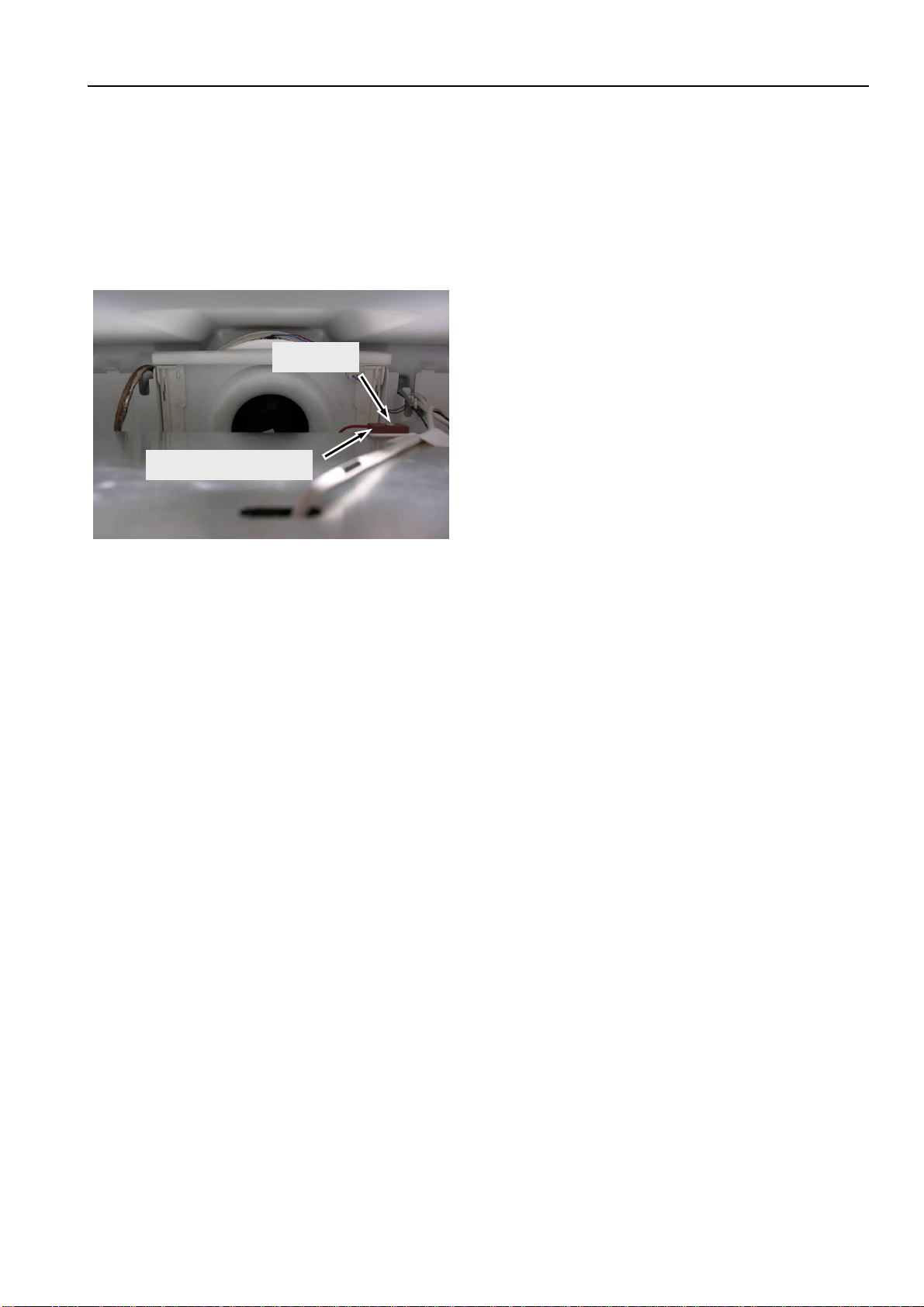
5.2.5 Temperature fuse
Evaporator module: Dismantle the evaporator module as described below under 5.2.1 Evaporator
module.
Temperature fuse: Fastened by a screw.
To be noted for replacement:
- Cut off only at the coloured wires (not heater wire!)
- Fix the wires in such a way that they do not touch the heater.
Fig. 5.2.5/ 1 Temperature fuse
Temperature fuse
Screw
Service Information No. 01/2008 IGN 2556/2566
Page 15/21
5.2.6 IGN 2566 only, IceMaker
Holder: Press the locating lugs in the two openings of the holder inwards and draw the holder forwards
for removal (see Fig. 5.2.6/ 1).
Reed contact: The reed contact for drawer recognition is situated in the holder.
IceMaker: Draw the IceMaker forwards and lower it for removal. Disconnect the IceMaker cables.
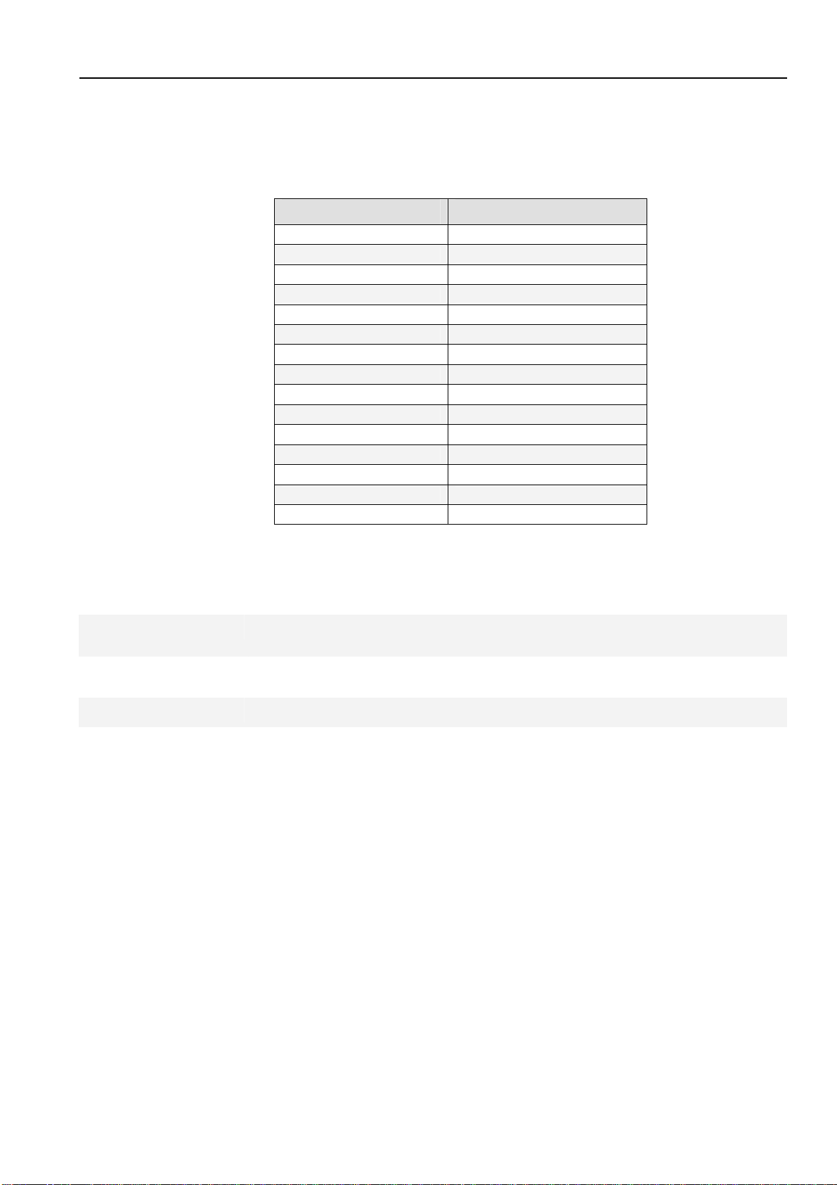
5.2.7 IGN 2566 only, double solenoid valve IceMaker
Solenoid valve - Undo marked screw (see Fig. 5.2.7/ 1).
- Remove cover.
- Detach electrical connectors.
- Undo screw fitting of water hose.
Holder
Fig. 5.2.6/ 1 Disengaging the holder
Holder with reed
contact
Fig. 5.2.6/ 2 Reed contact in holder
Fig. 5.2.6/ 3 IceMaker
Fi
g
. 5.2.7 / 1
Double solenoid valve
Fi
g
. 5.2.7 / 2
Screw fitting of
water hose
Electrical
connection
Service Information No. 01/2008 IGN 2556/2566
Page 16/21
6.0 Technical data
6.1 General
Sensor values:
Air and evaporator sensors
Temperature °C Resistance value kOhm
+35 3.1
+30 3.8
+25 4.7
+20 5.9
+15 7.3
+10 9.3
+5 11.9
0 15.3
-5 19.8
-10 25.9
-15 34.1
-20 45.3
-25 60.8
-30 82.3
-35 112.8
6.2 Freezer compartment
Fan:
Wattage: 1.6 watts
Voltage: 9 volts/DC
Defrost heater:
Wattage: 199 watts
Voltage: 230 volts/AC
Temperature fuse:
Tripping temperature: +93°C
Service Information No. 01/2008 IGN 2556/2566
Page 17/21
7.0 Service menu
The service menu may be used by service technicians only.
Activation of service menu: Press "ON/OFF" + "SuperFrost" simultaneously for about 3 seconds
Once the service menu is activated, the SuperFrost LED flashes.
7.1 Manual defrosting
Step Display Operation
Display following
operation
Testing option / Info
Service menu start
1 Actual value
Press "ON/OFF" and
"SuperFrost"
simultaneously for 3
seconds
"H" flashes with
SuperFrost LED
Service menu active.
Stepwise manual
defrosting.
Evaporator must be cold
1
"H" flashes together
with SuperFrost LED
Press "SuperFrost" "A" flashes Defrosting activated.
Manual defrosting is ended: - by switching appliance OFF/ON.
- automatically after the defrosting parameters have been reached.
(evaporator sensor +32°C or max. defrosting time 50 minutes)
7.2 Demo mode
Step Display Operation
Display following
operation
Testing option / Info
Service menu start
1 Actual value
Press "ON/OFF" and
"SuperFrost"
simultaneously for 3
seconds
"H" flashes with
SuperFrost LED
Service menu active.
Stepwise manual
defrosting.
2
"H" flashes with
SuperFrost LED
Press "Up" once
"d1" or "d0" flashes
with SuperFrost
LED
Service menu active.
Stepwise demo mode
3a
d1
Press SuperFrost. -18°C
Demo mode ON
3b
d0
Press SuperFrost. Actual value
Demo mode OFF
Demo mode (Demo mode can be deactivated only via service menu, not by OFF/ON.)
Operation switches to the mode wanted, demo mode or normal mode, as soon as "SuperFrost" has
been actuated.
Service Information No. 01/2008 IGN 2556/2566
Page 18/21
7.3 Service mode
Step Display Operation
Display following
operation
Testing option / Info
Service menu start
1 Actual value
Press
"ON/OFF" and
"SuperFrost"
simultaneously for 3
seconds
"H" flashes with
SuperFrost LED
Service menu active.
Stepwise manual
defrosting.
Service mode
-- test display LED, buttons, door contact --
1
"H" flashes with
SuperFrost LED
Press "Up" twice
"L" flashes with
SuperFrost LED
Service mode selected
2
"L" flashes with
SuperFrost LED
Press "SuperFrost" "rd" flashes Service mode activated
3 "rd" flashes Door closed and open
All button LEDs and
display segments
shine
Door contact, LEDs,
display
4
All button LEDs and
display segments
shine
Press all the buttons
- "L0" shines
- 2 seconds beep
Buttons / button actuation
is confirmed by beep
After step 4, actuation of the last button, a beep sounds.
Service mode
-- Testing electric loads--
Power
input1)
5 "L0" shines No operation
"L0" shines All OFF
--
6 "L0" shines Press "Up"
"L1" shines
Compressor ON
low speed
--
7 "L1" shines Press "Up"
"L4" shines Defrost heater ON
199 watts
8 "L4" shines Press "Up"
"L7" shines
Fan ON
low speed
1.4 watts
9 "L7" shines Press "Up"
"L8" shines
Fan ON
high speed
1.6 watts
Return to step 5 is brought about by pressing the up button again.
End Press "ON/OFF"
1) Power input = power input of the appliance in the respective testing step!
Service Information No. 01/2008 IGN 2556/2566
Page 19/21
7.4 Sensor test (temperature display) and door contact test "E"
Step Display Operation
Display following
operation
Testing option / Info
Service menu start
1 Actual value
Press "ON/OFF" und
"SuperFrost"
simultaneously for 3
seconds
"H" flashes with
SuperFrost LED
Service menu active.
Stepwise manual
defrosting.
Sensor test and door contact test (sensor values without offset, appliance in control mode)
1
"H" flashes with
SuperFrost LED
Press "Up" three times
"E" flashes with
Superfrost LED
Sensor test mode selected
2
"E" flashes with
Superfrost LED
Press "SuperFrost"
"E3" flashes
alternately with
sensor temperature
Air sensor
3
"E3" flashes
alternately with sensor
temperature
Press "Up"
"E4" flashes
alternately with
sensor temperature
Evaporator sensor
4
"E4" flashes
alternately with sensor
temperature
Press "Up"
"E7" flashes
alternately with
sensor temperature
Ambient sensor
5
"E7" flashes
alternately with sensor
temperature
Press "Up"
"E8" flashes
alternately with
"1" or display is
OFF
Door contact
(display OFF=door closed,
1=door open)
End Press ON/OFF twice
8.0 Error code, troubleshooting
8.1 Table of error codes
Error code Defective component Emergency mode
F3 Freezer compartment air sensor
Compressor switches OFF.
Info:
Compressor switches ON again only when the
appliance has been switched OFF and on again.
F4
Freezer compartment evaporator
sensor
Compressor continuous operation (highest speed)
ru Ambient sensor
Appliance continues to operate in normal mode,
only without regard to the ambient temperature.
Info:
Is displayed only in the service mode of the service
menu, in step 2 instead of "rd".
Service Information No. 01/2008 IGN 2556/2566
Page 20/21
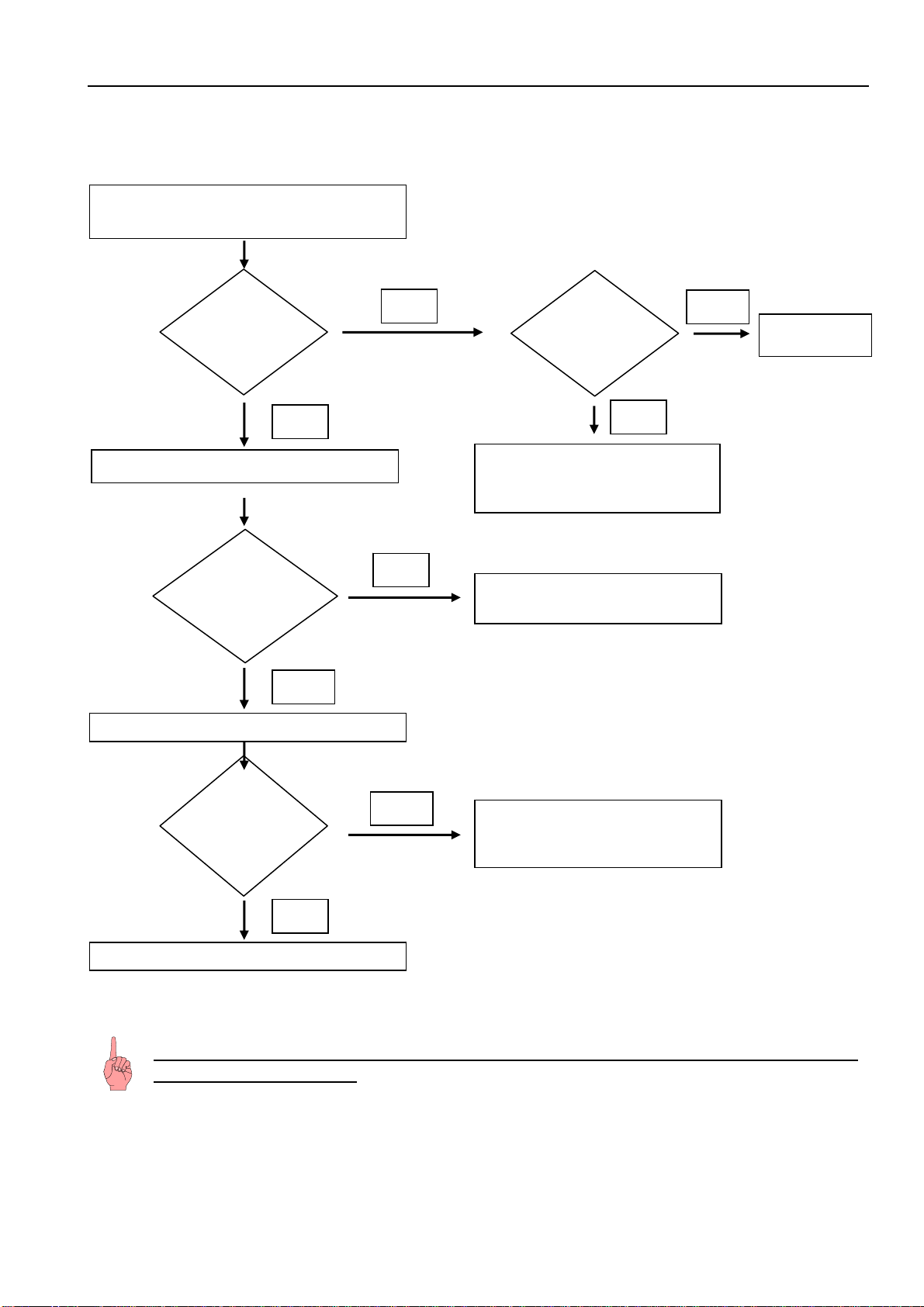
8.2 Troubleshooting VCC compressor / inverter
8.2.1 Checking the inverter and the frequency signal
Attention: In case of interruption of the frequency signal, the compressor starts
only after 90 seconds!!
Is the
compressor
running?
Frequency signal faulty / not
connected or power PCB faulty.
No
Connect appliance to a power meter.
Switch appliance ON.
Yes
Does the speed
increase, higher
power input?
No
Does the
compressor
stay at a
standstill?
Press SuperFrost
Yes
Inverter; power PCB and the
frequency cable are OK.
Is
the compressor
running after 90
seconds?
Yes
see 8.2.2
No
Switch a
pp
liance OFF
No
Yes
Inverter fault
y
Frequency signal faulty / not
connected or power PCB faulty.
Service Information No. 01/2008 IGN 2556/2566
Page 21/21
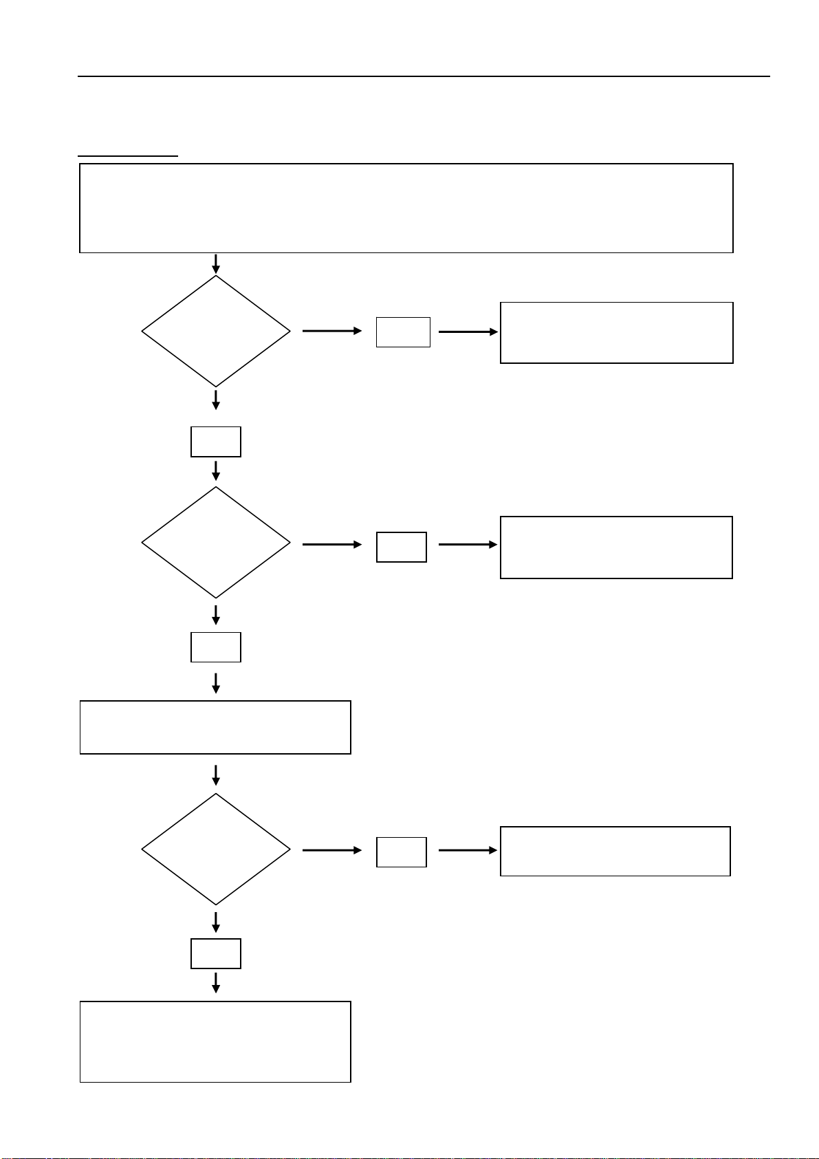
8.2.2 Checking the compressor
Fault profile: Compressor does not run (even after a waiting time of 90 seconds)
Select step 6 (compressor ON) in the service menu under "7.3 service mode". If the compressor now
starts there was probably an operator error. Otherwise proceed as described below.
At the inverter, line voltage (230V) must be applied between N and 1/C.
Pull off frequency signal connector (lilac)
from the inverter, wait 90 secs.
Replace inverter electronic module.
If the compressor still does not run,
replace the compressor.
Then replace the inverter back again.
Yes
Presumably operator error.
Check speed increase!
No
Is voltage
applied to the
inverter?
Is the
compressor
running?
Is the
compressor
running?
No
Yes
Yes
No
Fault at cable connection /
connector or power PCB.
Power PCB or inverter fault.