SEWING
MACHINE
CABINET
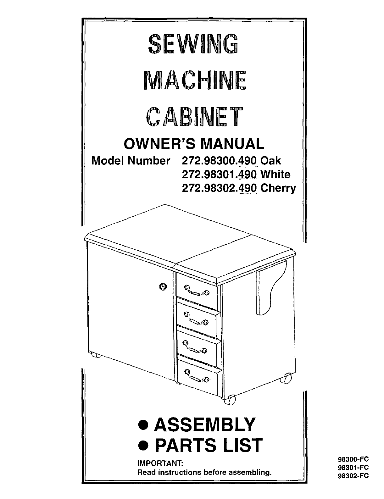
OWNER'S MANUAL
Model Number 272.98300.490 Oak
272.98301.4_90 White
272.98302.490 Cherry
ASSEMBLY
PARTS LIST
98300-FC
98301-FC
98302-FC
IMPORTANT:
Read instructions before assembling.
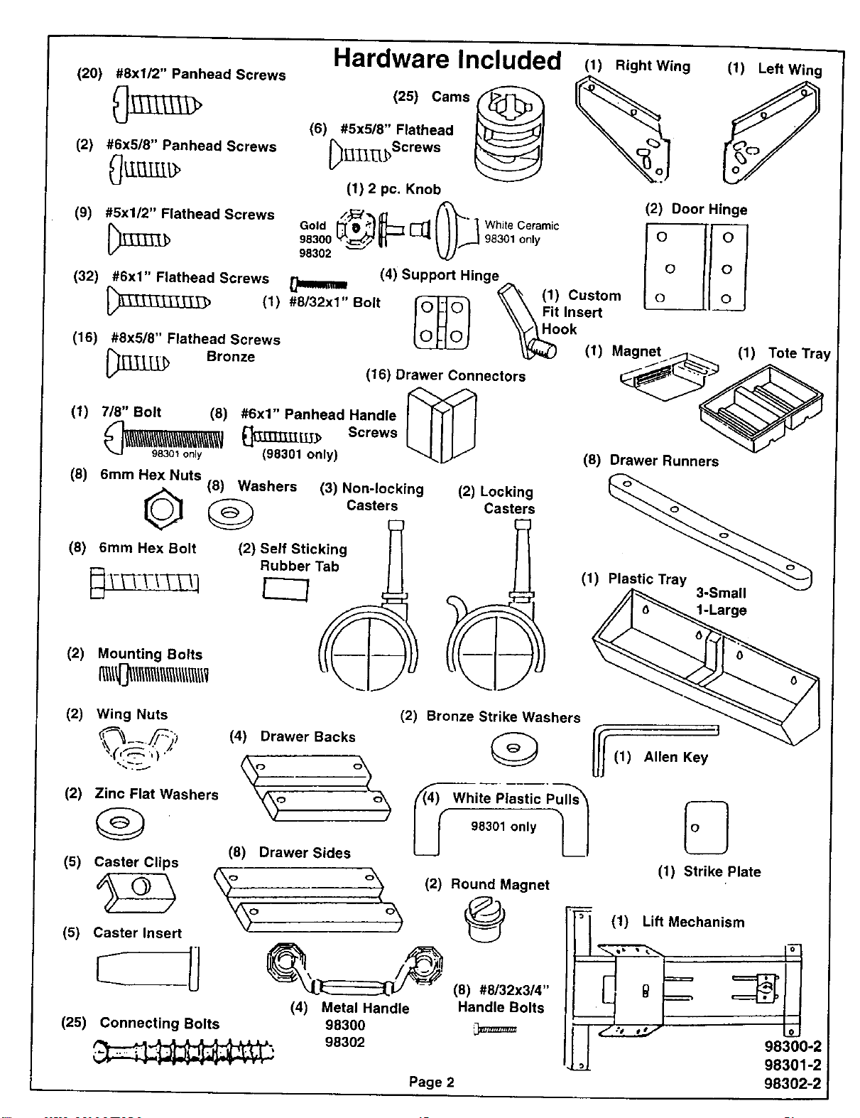
(20) #8xl/2" Panhead Screws
(2) #6x5/8" Panhead Screws
Hardware Included
,o,
(1) 2 pc. Knob
(1) Right Wing
%
(1) Left Wing
(2) Door Hinge
(9) #5x1/2" Flathead Screws Gold t_/F_ P,_L-- _ (_" _ Wh te Ceramic H
983o0%j_ IM,030,on,, I° IIoI
98302 _j' I II 0 I
(4) Support Hinge _ I 0 /[ /
(32) #8x1" Flathead Screws ,, _ '_'_ (1) Custom o___l O_
_"_'T_:> (1) #9/32xl Bolt IOJ_]© I _x_ Fitlnsert
loHol _?_ook
(16) #8x5/8" Flathead Screws _ _ (1) Magnet (1)
_____ Bronze (16) Drawer Connectors
(1) 7/8" Bolt (8) #6x1" Panhead Handle [_X_[
_'_ i\_\\_\_ _LU._ Screws
".J 98301 only (98301 only)
(8) 6mm HexNuts
0
(8) 6mm Hex Bolt
(8) Washers (3) Non-locking (2) Locking
Casters Casters
(2) Self Sticking [I
Tab
Rubber[_ _
Tote Tray
(2) Mounting Bolts
(8) Drawer Runners
(1)
3-Small
1-Large
(2) Wing Nuts
(2) Zinc Flat Washers
(g)
(5) Caster Clips
(5) Caster Insert
(25) Connecting Bolts
(4) Drawer Backs
\o o\
(2) Bronze Strike Washers
_ White_,astic___
U 98301 only
(8) Drawer Sides
(2) Round Magnet
\o % @
(4) Metal Handle Handle Bolts
98300 ,_
98302
Page 2
I
(1) Allen Key
(1) Strike Plate
_,_(1) Lift Mechanism
98300 2
98301-2
98302-2
I
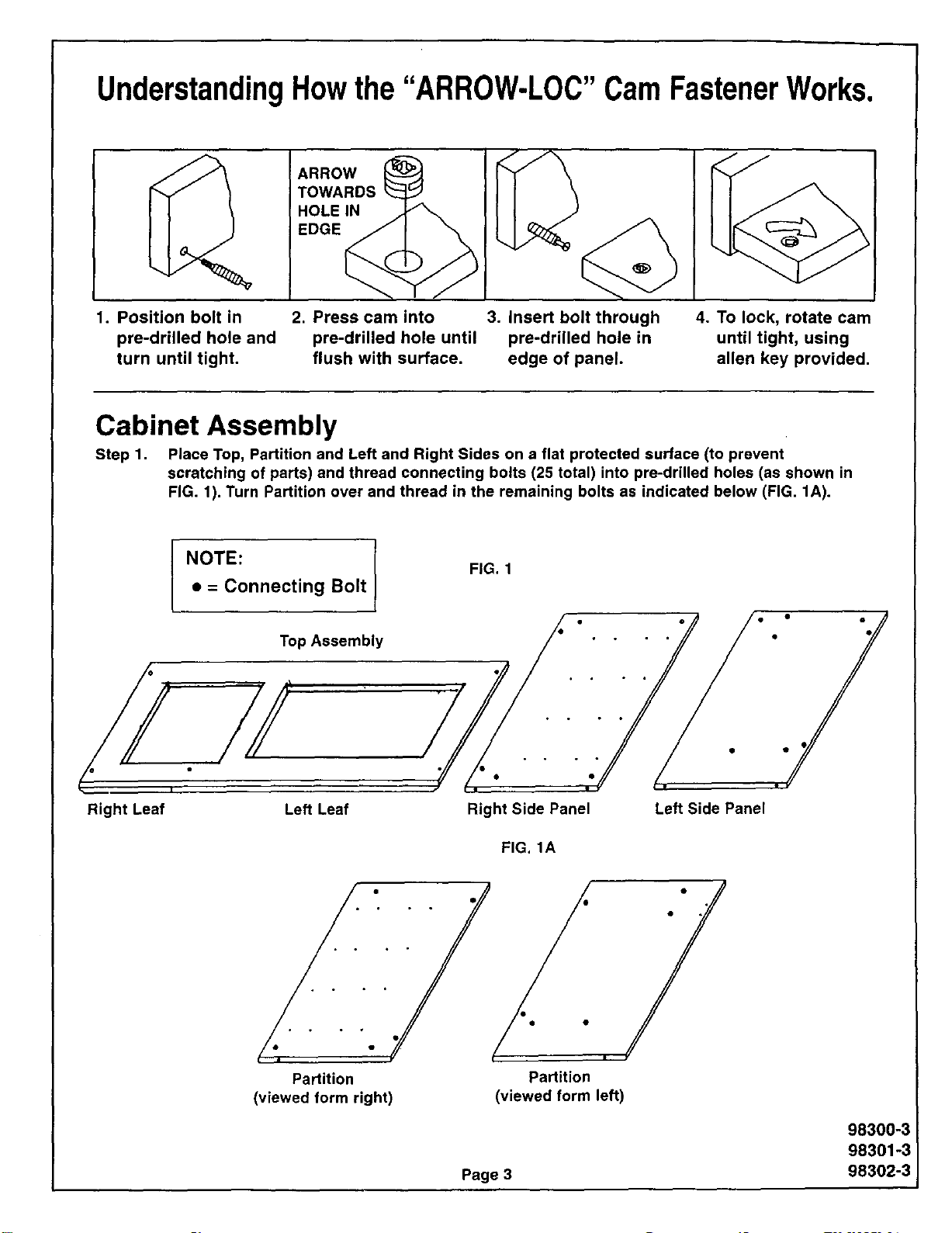
UnderstandingHowthe"ARROW-LOC"CamFastenerWorks.
ARROW
TOWARDS
HOLEIN
EDGE
1. Position bolt in 2. Press cam into 3. Insert bolt through
pre-drilled hole and pre-drilled hole until pre-drilled hole in
turn until tight, flush with surface, edge of panel.
4. To lock, rotate cam
until tight, using
allen key provided.
Cabinet Assembly
Step 1. Place Top, Partition and Left and Right Sides on a flat protected surface (to prevent
scratching of parts) and thread connecting bolts (25 total) into pre-drilled holes (as shown in
FIG. 1). Turn Partition over and thread in the remaining bolts as indicated below (FIG. 1A).
Right Leaf
NOTE:
• = Connecting Bolt
Top Assembly
Left Leaf
FIG. 1
Right Side Panel
FIG. 1A
Left Side Panel
• • • • 4"
Partition Partition
(viewed form right) (viewed form left)
Page 3
98300-3
98301-3
98302-3
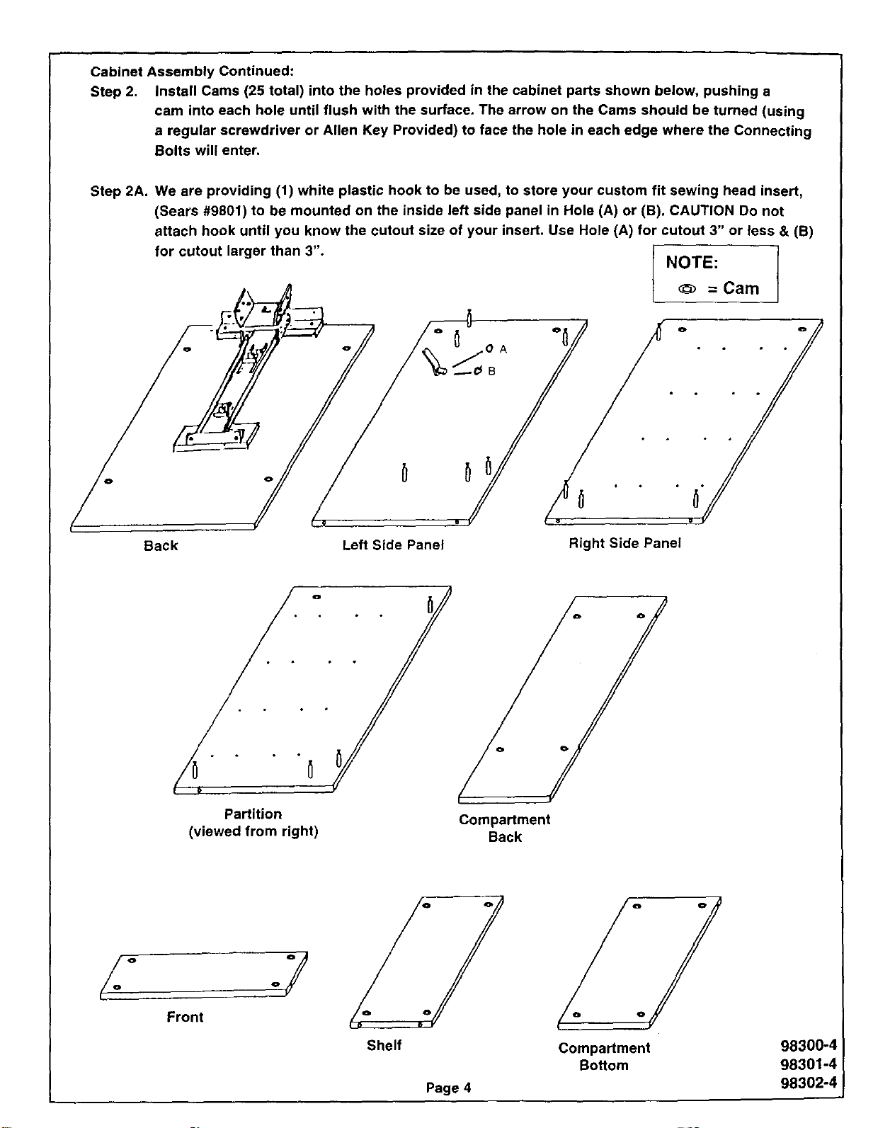
Cabinet Assembly Continued:
Step 2. Install Cams (25 total) into the holes provided in the cabinet parts shown below, pushing a
cam into each hole until flush with the surface. The arrow on the Cams should be turned (using
a regular screwdriver or Allen Key Provided) to face the hole in each edge where the Connecting
Bolts will enter.
Step 2A. We are providing (1) white plastic hook to be used, to store your custom fit sewing head insert,
(Sears #9801) to be mounted on the inside left side panel in Hole (A) or (B). CAUTION Do not
attach hook until you know the cutout size of your insert. Use Hole (A) for cutout 3" or less & (B)
for cutout larger than 3". NOTE:
= Cam
Back Left Side Panel Right Side Panel
°
"o° _ • o°
Partition
(viewed from right)
Compartment
Back
Front
.y
Shelf
Page 4
Compartment
Bottom
98300-4
98301-4
98302-4
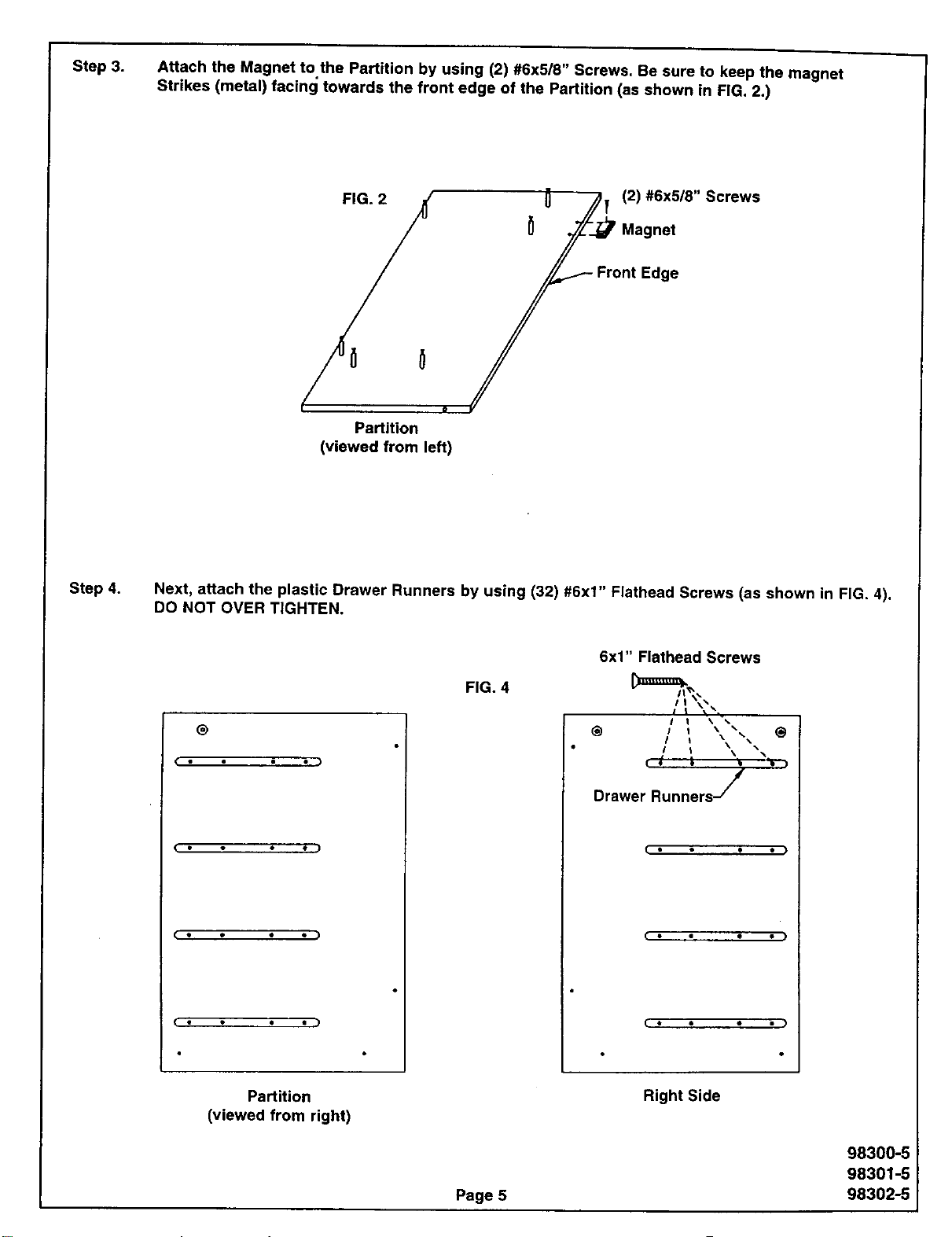
Step 3. Attach the Magnet to.the Partition by using (2) #6x5/8" Screws. Be sure to keep the magnet
Strikes (metal) facing towards the front edge of the Partition (as shown in FIG, 2.)
FIG. 2 .4_ 0 ./_y (2) #6x5/8" Screws
/ _ f__Magnet
/°°/
Partition
(viewed from left)
Step 4.
Next, attach the plastic Drawer Runners by using (32) #6x1" Flathead Screws (as shown in FIG. 4).
DO NOT OVER TIGHTEN.
®
( • • • )
(. • • ./
FIG. 4
6x1" Flathead Screws
@ / I
Drawer Runners /
I • • • • )
Partition
(viewed from right)
Page 5
Right Side
98300-5
98301-5
98302-5
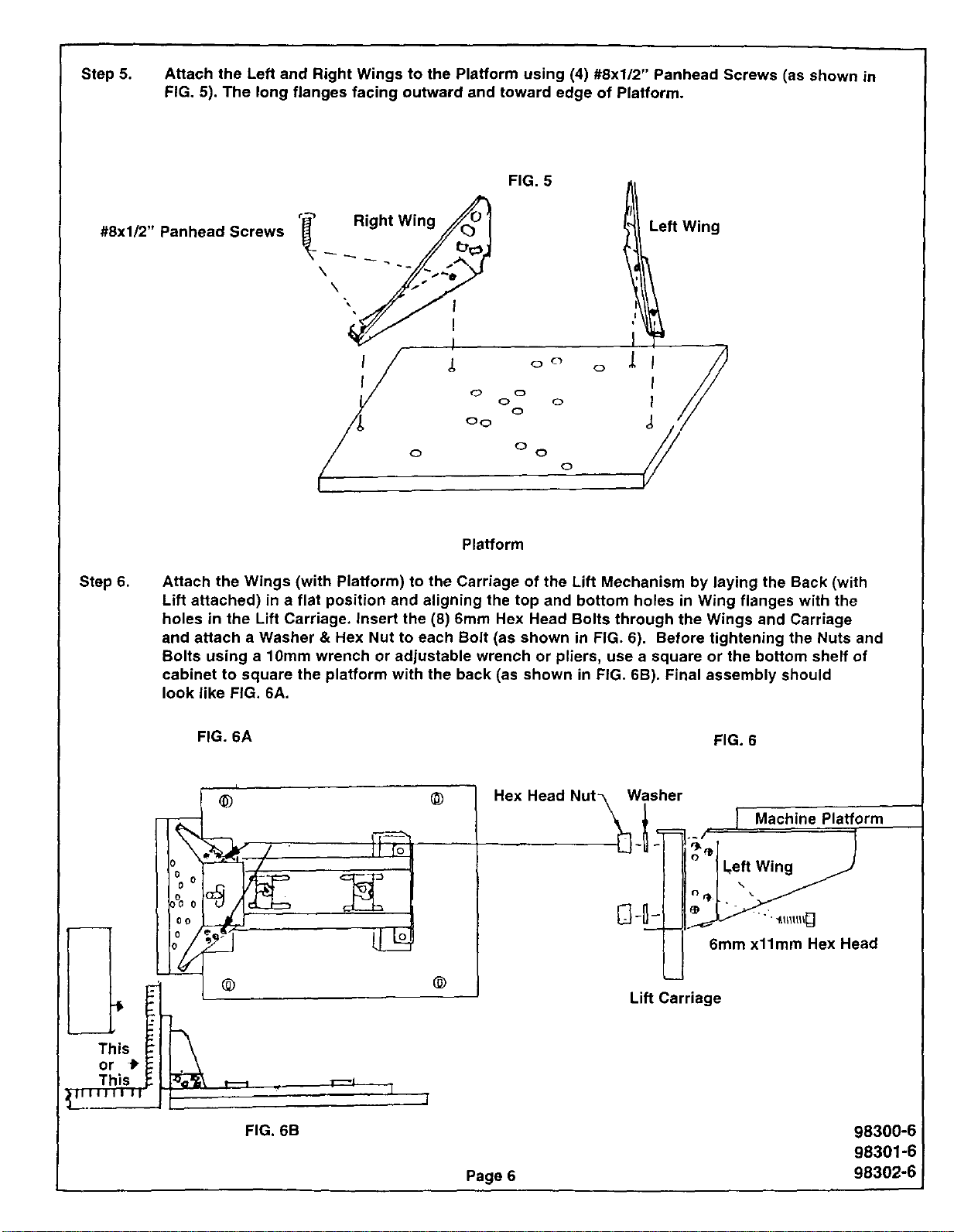
Step 5. Attach the Left and Right Wings to the Platform using (4) #8xl/2" Panhead Screws (as shown in
FIG. 5). The long flanges facing outward and toward edge of Platform.
#8xl/2" Panhead Screws
FIG. 5
",,//// i
°cl
0
0 0
0
0
0
o
Left Wing
Ii
I
I
Step 6.
Platform
Attach the Wings (with Platform) to the Carriage of the Lift Mechanism by laying the Back (with
Lift attached) in a flat position and aligning the top and bottom holes in Wing flanges with the
holes in the Lift Carriage. insert the (8) 6mm Hex Head Bolts through the Wings and Carriage
and attach a Washer & Hex Nut to each Bolt (as shown in FIG. 6). Before tightening the Nuts and
Bolts using a 10mm wrench or adjustable wrench or pliers, use a square or the bottom shelf of
cabinet to square the platform with the back (as shown in FiG. 6B). Final assembly should
look like FiG. 6A.
FIG. 6A FIG. 6
3
This
or _"
This
FIG. 6B
@
@
Lift Carriage
Page 6
Machine Platform
Left Wing
•"f.l_lllll_]
6mm x11mm Hex Head
98300-6
98301-6
98302-6j
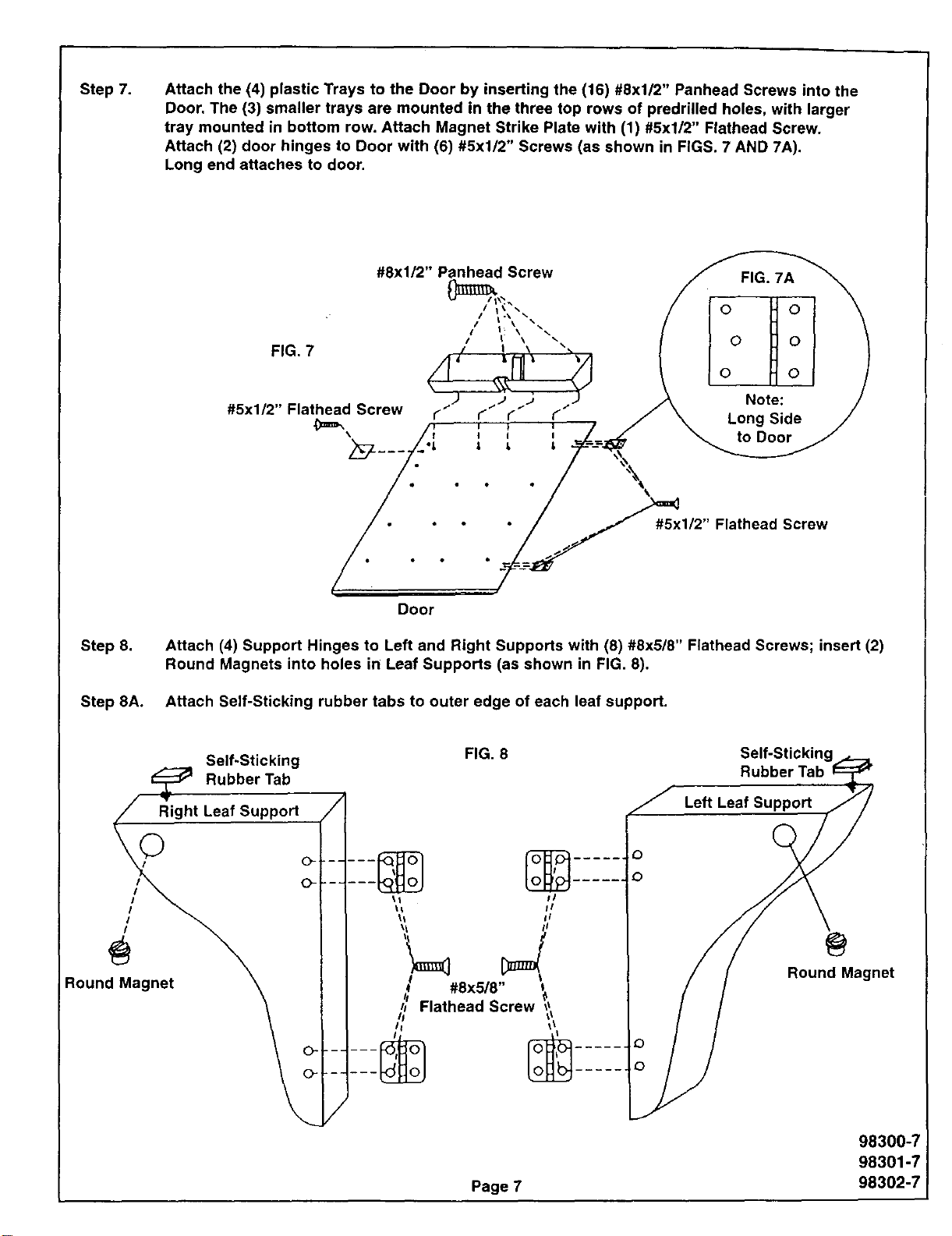
Step 7. Attach the (4) plastic Trays to the Door by inserting the (16) #8xl/2" Panhead Screws into the
Door. The (3) smaller trays are mounted in the three top rows of predrilled holes, with larger
tray mounted in bottom row. Attach Magnet Strike Plate with (1) #5xl/2" Flathead Screw.
Attach (2) door hinges to Door with (6) #5xl/2" Screws (as shown in FIGS. 7 AND 7A).
Long end attaches to door.
#8xl/2" Panhead Screw FIG. 7A
t I \ 0 0
0
#5x1/2" Flathead Screw ¢I)¢.. J / Note:
l" Long Side
_'=_ I i , to Door
FIG. 7
#5xl/2" Flathead Screw
Step 8.
Step 8A.
Door
Attach (4) Support Hinges to Left and Right Supports with (8) #8x5/8" Flathead Screws;
Round Magnets into holes in Leaf Supports (as shown in FIG. 8).
Attach Self-Sticking rubber tabs to outer edge of each leaf support.
insert (2)
Self-Sticking
Rubber Tab
pport
II
iI
i I
R°undMagnet __ _ #8X5/8'' '
I I _1 Flathead Screw t_t
FIG. 8 Self-Sticking
Rubber Tab
Page 7
Left Leaf Support
@
Round Magnet
98300-7
98301-7
98302-7
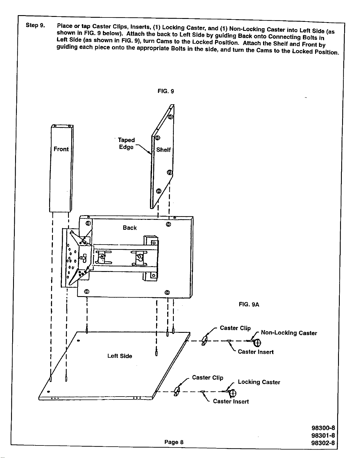
Step 9. Place or tap Caster Clips, Inserts, (1) Locking Caster, and (1) Non-Locking Caster into Left Side (as
shown in FIG. 9 below). Attach the back to Left Side by guiding Back onto Connecting Bolts in
Left Side (as shown in FiG. 9), turn Cams to the Locked Position. Attach the Shelf and Front by
guiding each piece onto the appropriate Bolts in the side, and turn the Cams to the Locked Position.
FIG. 9
.w--'---.w
Front
t ©
I
; 1
I I
/
J
Taped
Edge
f io
@
Back
@
t _lt Fla.gA
t ;t
J io
! j t ._- Caster Clipr Non-Locking
/// \" Caster Insert
Left Side " //
//
r_iCaster CI_ Locking Caster
...,.
Caster
Page 8
98300-8
98301-8
98302-8
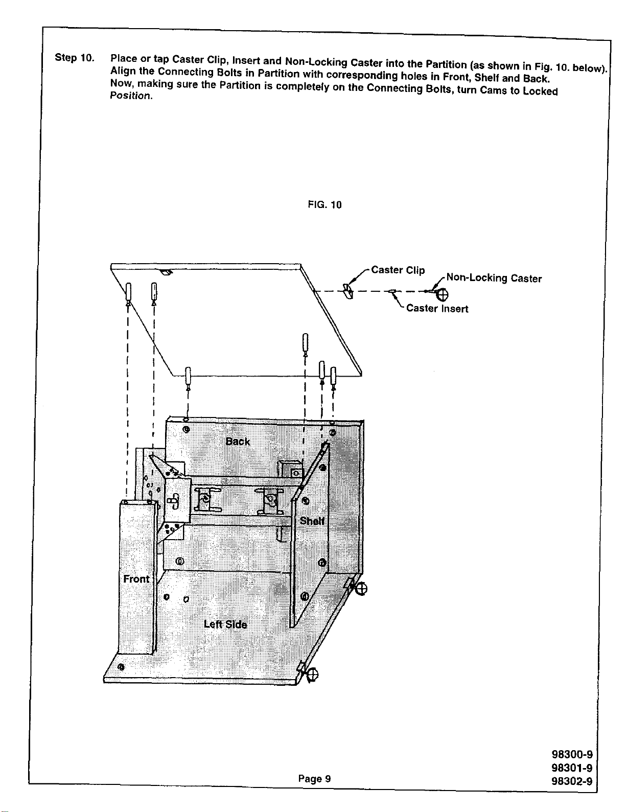
Step 10.
Place or tap Caster Clip, Insert and Non-Locking Caster into the Partition (as shown in Fig. 10. below).
Align the Connecting Bolts in Partition with corresponding holes in Front, Shelf and Back.
Now, making sure the Partition is completely on the Connecting Bolts, turn Cams to Locked
Position.
FIG. 10
._Non-Locking Caster
--- ;a sert
Page 9
98300-9
98301-9
98302-9
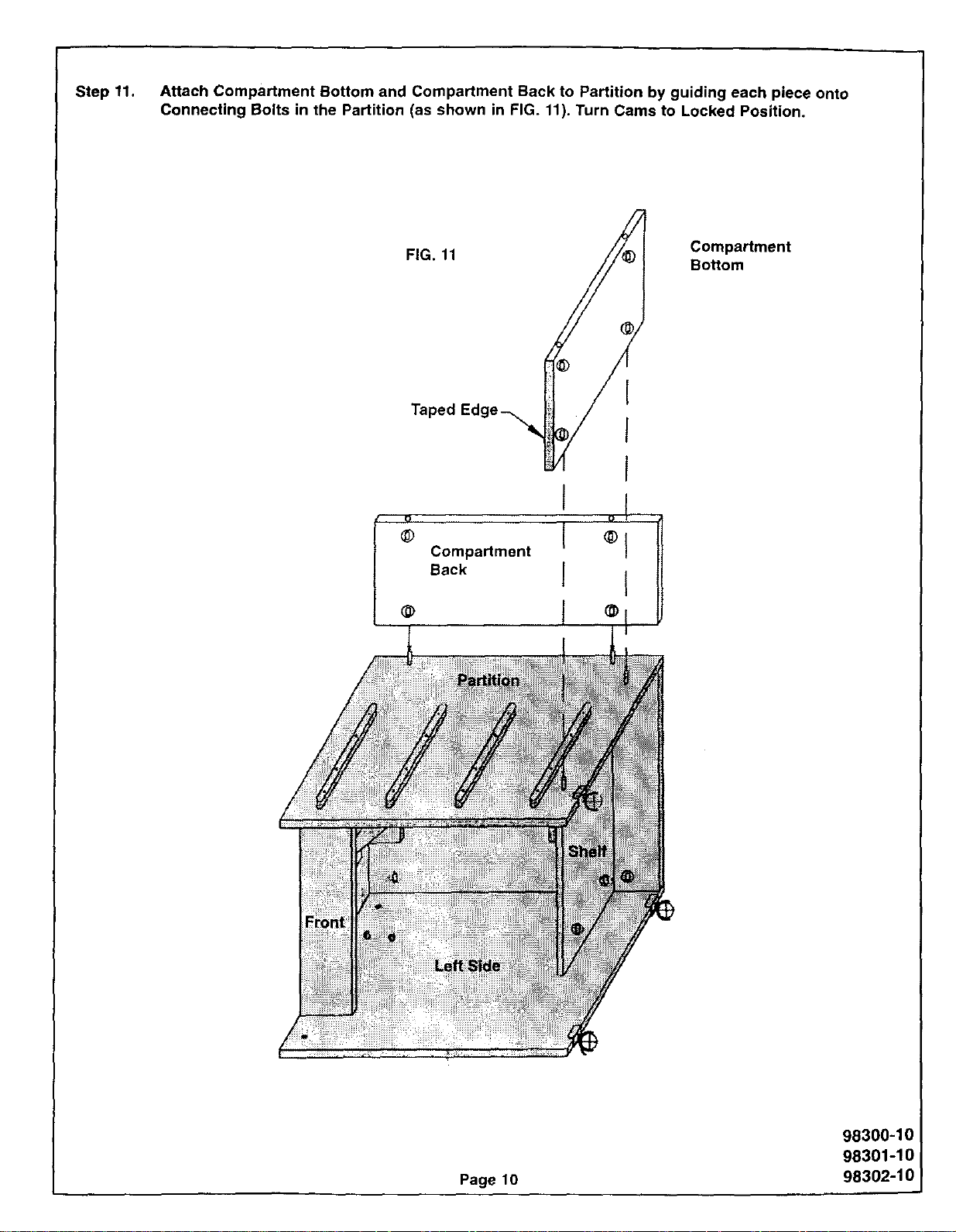
Step 11. Attach Compartment Bottom and Compartment Back to Partition by guiding each piece onto
Connecting Bolts in the Partition (as shown in FIG. 11). Turn Cams to Locked Position.
FIG. 11 Compartment
Bottom
Taped
@
@
Compartment
Back
I
I o!
I ®l
I I
,I
Page 10
98300-10
98301-10
98302-10
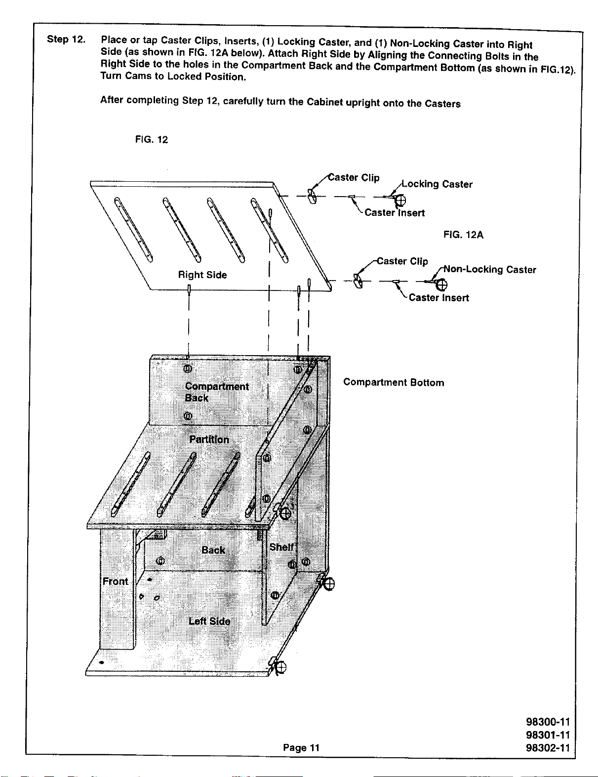
Step 12. Place or tap Caster Clips, Inserts, (1) Locking Caster, and (1) Non-Locking Caster into Right
Side (as shown in FIG. 12A below). Attach Right Side by Aligning the Connecting Bolts in the
Right Side to the holes in the Compartment Back and the Compartment Bottom (as shown in FIG.12).
Turn Cams to Locked Position.
After completing Step 12, carefully turn the Cabinet upright onto the Casters
FIG. 12
Right Side
Y
{
Compartment Bottom
Page11
98300-11
98301-11
98302-11
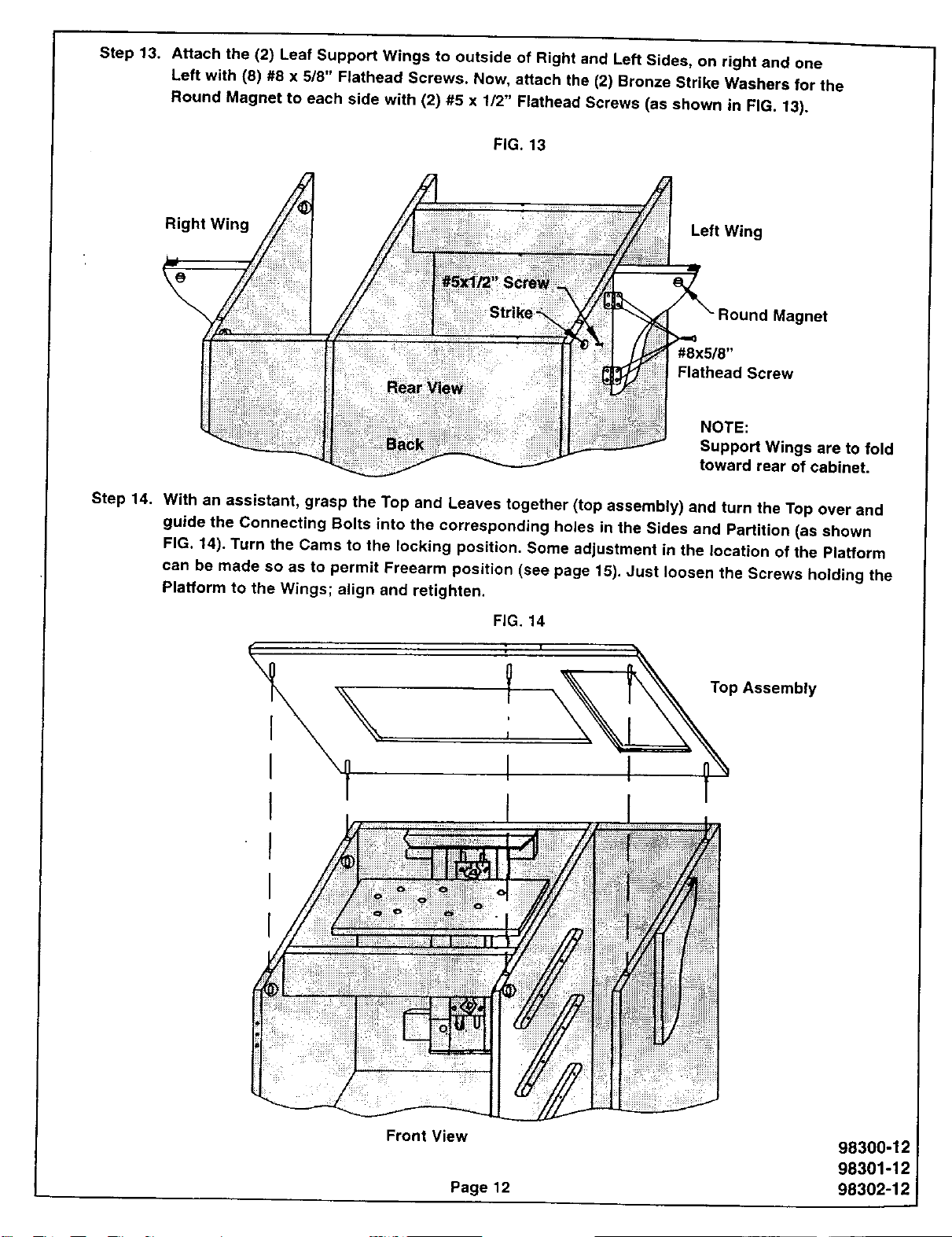
Step 13. Attach the (2) Leaf Support Wings to outside of Right and Left Sides, on right and one
Left with (8) #8 x 5/8" Flathead Screws. Now, attach the (2) Bronze Strike Washers for the
Round Magnet to each side with (2) #5 x 1/2" Flathead Screws (as shown in FIG. 13).
FiG. 13
Right Left Wing
#8x5/8"
Flathead Screw
NOTE:
Support Wings are to fold
toward rear of cabinet.
Step 14. With an assistant, grasp the Top and Leaves together (top assembly) and turn the Top over and
guide the Connecting Bolts into the corresponding holes in the Sides and Partition (as shown
FIG. 14). Turn the Cams to the locking position. Some adjustment in the location of the Platform
can be made so as to permit Freearm position (see page 15). Just loosen the Screws holding the
Platform to the Wings; align and retighten.
FiG. 14
Y
J
I
' __nTop Assembly
I1
Front View 98300-12
98301-12
Page 12 98302-12
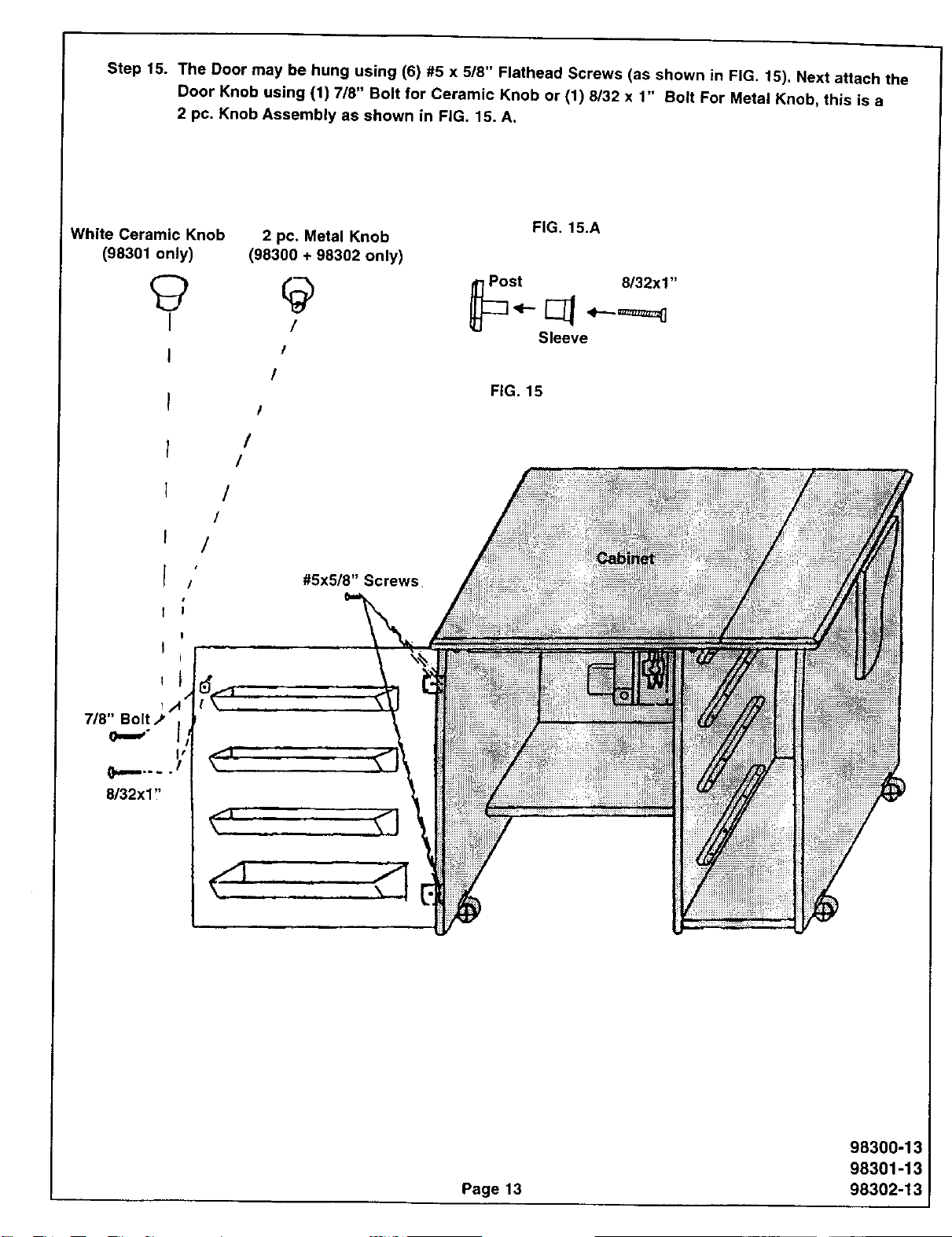
Step 15. The Door may be hung using (6) #5 x 5/8" Flathead Screws (as shown in FIG. 15). Next attach the
Door Knob using (1) 7/8" Bolt for Ceramic Knob or (1) 8/32 x 1" Bolt For Metal Knob, this is a
2 pc. Knob Assembly as shown in FIG. 15. A.
White Ceramic Knob
(98301 only)
FIG. 15.A
2 pc. Metal Knob
(98300 + 98302 only)
!
Sleeve
I
/
I
/
/
/
/
#5x5/8" Screws
FiG. 15
Page 13
98300-13
98301-13
98302-13
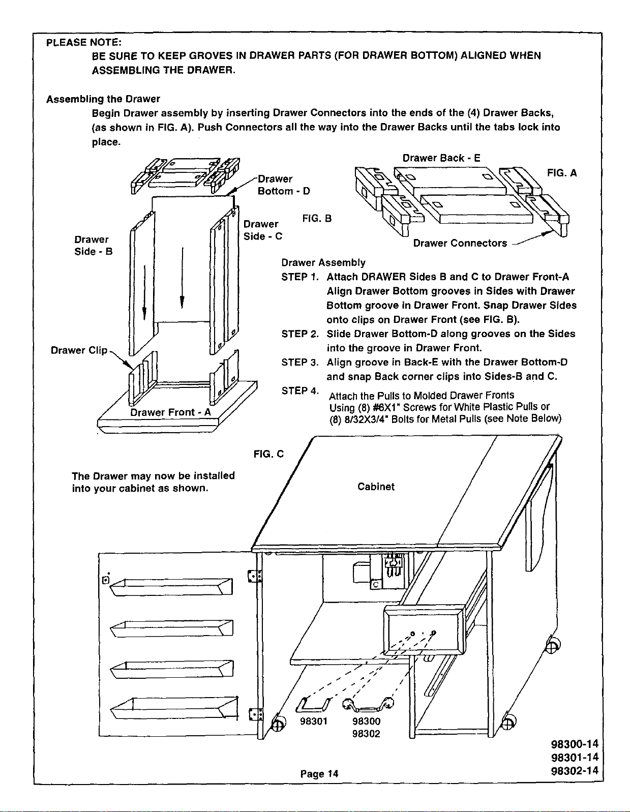
PLEASE NOTE:
BE SURE TO KEEP GROVES IN DRAWER PARTS (FOR DRAWER BOTTOM) ALIGNED WHEN
ASSEMBLING THE DRAWER.
Assembling the Drawer
Begin Drawer assembly by inserting Drawer Connectors into the ends of the (4) Drawer Backs,
(as shown in FIG. A). Push Connectors all the way into the Drawer Backs until the tabs lock into
place.
Drawer
Side - B
Drawer Cli
F/_/_o ,=_ Drawer Back - E
J_ /Drawer _--_,,_ _ FIG. A
°o.omo
Jl DrawerF, .B .
II ] II I Side-C _ _u
II I II I Drawer Connectors _'_
II I I I II I Drawer Assembly
[I I I I II I STEP1. Attach DRAWER Sides B and C to Drawer Front-A
I I I I I_ II J Align Drawer Bottom grooves in Sides with Drawer
Illl ' Ill Bottom groove in Drawer Front. Snap Drawer Sides
I( ' _-_'_l ( onto clips on Drawer Front (see FIG. B).
II /I) [I.! STEP2. Slide Drawer Bottom-D along grooves on the Sides
L_'A1 ELY.)1 into the groove in Drawer Front,
_._ll )_( STEP 3. Align groove in Back-E with the Drawer Bottom-D
N II_J_====_. _/L-_ and snap Back c°rner clips int° Sides'B and C"
LjF/// STEP 4. Attach the Pulls to Molded Drawer Fronts
Drawer Front - A_// Using (8) #6Xl Screws for White Plastic Pulis or
(8) 8132X314"Boltsfor Metal Pulls (see Note Below)
The Drawer may now be installed
into your cabinet as shown.
I
v_
•_ f t"/
/ 7 t/I/ (
/ I ._ "_/ /
f _" p. •
98301 98300 I_
98302 LF
Page 14
Cabinet / _
98300-1_
98301-14
98302-14
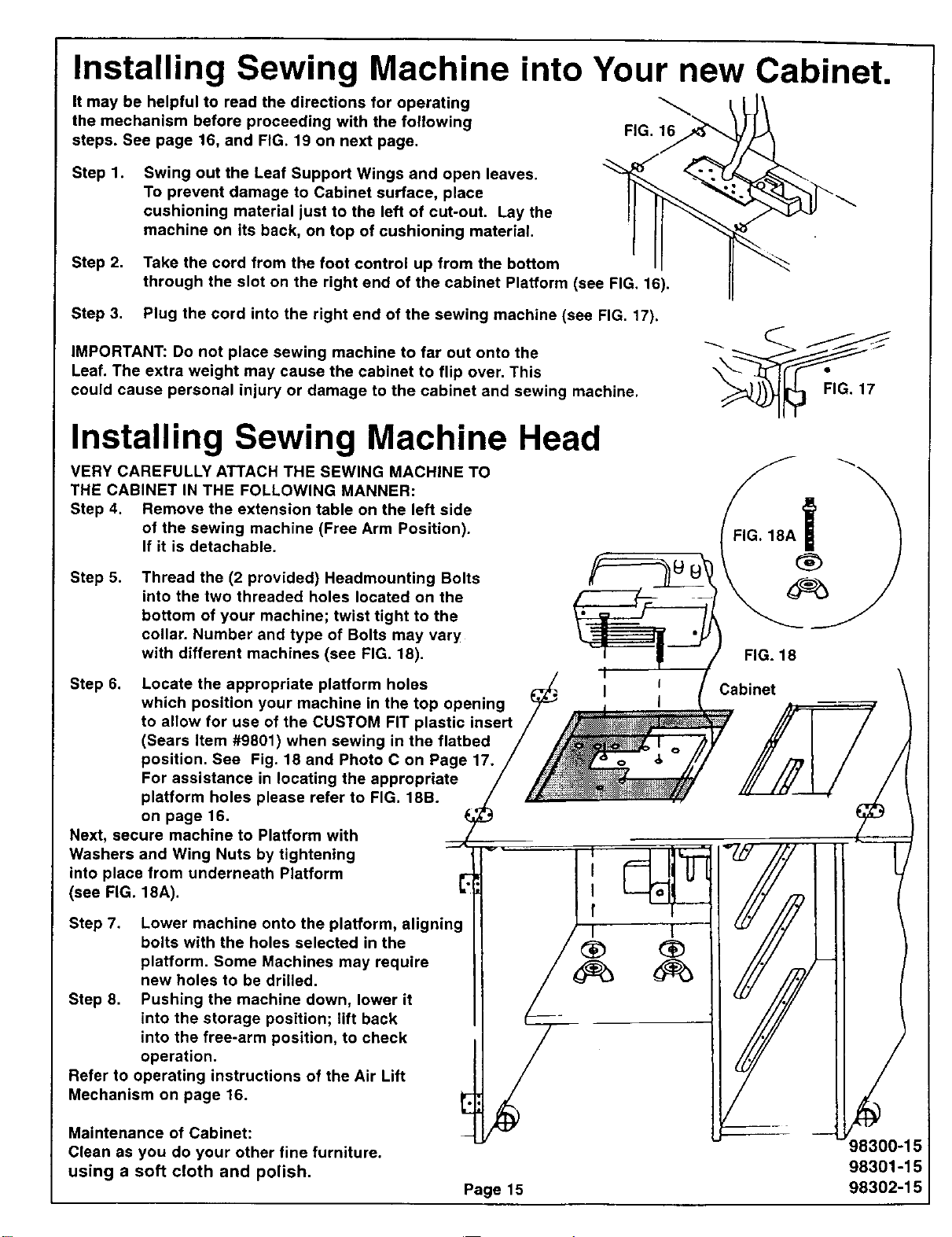
Installing Sewing Machine into Your new Cabinet.
It may be helpful to read the directions for operating
the mechanism before proceeding with the following FIG. 16
steps. See page 16, and FIG. 19 on next page.
Step 1. Swing out the Leaf Support Wings and open leaves.
To prevent damage to Cabinet surface, place
cushioning material just to the left of cut-out. Lay the
machine on its back, on top of cushioning material.
Step 2. Take the cord from the foot control up from the bottom
through the slot on the right end of the cabinet Platform (see FIG, 16).
Step 3. Plug the cord into the right end of the sewing machine (see FIG. 17).
IMPORTANT: Do not place sewing machine to far out onto the
Leaf. The extra weight may cause the cabinet to flip over. This
could cause personal injury or damage to the cabinet and sewing machine.
Installing Sewing Machine Head
VERY CAREFULLY ATTACH THE SEWING MACHINE TO
THE CABINET IN THE FOLLOWING MANNER:
Step 4. Remove the extension table on the left side
of the sewing machine (Free Arm Position).
If it is detachable.
Step 5. Thread the (2 provided) Headmounting Bolts
into the two threaded holes located on the
bottom of your machine; twist tight to the
collar. Number and type of Bolts may vary
with different machines (see FIG. 18).
Step 6. Locate the appropriate platform holes
which position your machine in the top opening
to allow for use of the CUSTOM FIT plastic insert
(Sears Item #9801) when sewing in the flatbed
position. See Fig. 18 and Photo C on Page 17.
For assistance in locating the appropriate
platform holes please refer to FIG. 18B.
on page 16.
Next, secure machine to Platform with
Washers and Wing Nuts by tightening
into place from underneath Platform
(see FIG. 18A).
Step 7. Lower machine onto the platform, aligning
bolts with the holes selected in the
platform. Some Machines may require
new holes to be drilled.
Step 8. Pushing the machine down, lower it
into the storage position; lift back
into the free-arm position, to check
operation.
Refer to operating instructions of the Air Lift
Mechanism on page 16.
Maintenance of Cabinet:
Clean as you do your other fine furniture.
using a soft cloth and polish.
Page 15
f
I 1
FIG. 18A1
FIG. 18
Cabinet
!
_8300-15
98301-15
98302-15
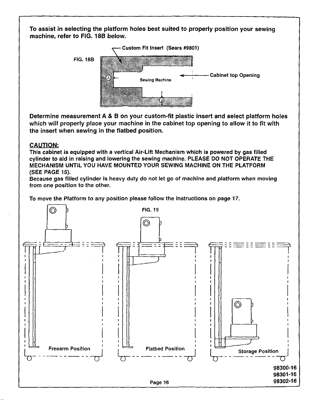
To assist in selecting the platform holes best suited to properly position your sewing
machine, refer to FIG. 18B below.
Insert (Sears#9801)
FIG.18B
I
Cabinet top Opening
Determine measurement A & B on your custom-fit plastic insert and select platform holes
which will properly place your machine in the cabinet top opening to allow it to fit with
the insert when sewing in the flatbed position.
CAUTION:
This cabinet is equipped with a vertical Air-Lift Mechanism which is powered by gas filled
cylinder to aid in raising and lowering the sewing machine. PLEASE DO NOT OPERATE THE
MECHANISM UNTIL YOU HAVE MOUNTED YOUR SEWING MACHINE ON THE PLATFORM
(SEE PAGE 15).
Because gas filled cylinder is heavy duty do not let go of machine and platform when moving
from one position to the other.
To move the Platform to any position please follow the instructions on page 17.
Iii
I I
I
H
I
I
I
I
I
I
I
I
I
I
I
I
I
I
Freearm Position
FIG. 19
k_ Flatbed Position
U
1
Page 16
Storage Position
98300-16
98301-16
98302-16

HOW TO MOVE YOUR MACHINE To move machine from flatbed to storage (see Photos
FROM ONE POSITION TO ANOTHER C,D&E.
To move machine from free arm to flatbed (see Photos
A, B & C).
GENTLY push down on sewing machine until you hear
a "click."
The sewing machine is now locked in place at the
flatbed position.
GENTLY push down on sewing machine until you hear
a "click."
The sewing machine is now locked in place at the stor-
age position.
NOTE: Your mechanism is adjustable. You can adjust f_,._
up or down by loosening the 2 hex nuts on the cam
lock, After moving to the desired position retighten.
/
PHOTO A-FREE ARM POSITION '
PHOTO B
PHOTO C-FLATBED POSITION
Page17
PHOTO D
PHOTO E-STORAGE POSITION
To move machine from storage to flatbed (see Photos
E&C).
VERY GENTLY push down until you hear a "click" and
release.
The sewing machine will now move up to the flatbed
position.
To move machine from flatbed to free arm (see Photos
C& B).
VERY GENTLY push down until you hear a click and
release.
The sewing machine will now move up to the the free
arm position. For some machines you may have to lift
slightly to lock into the freearm position.
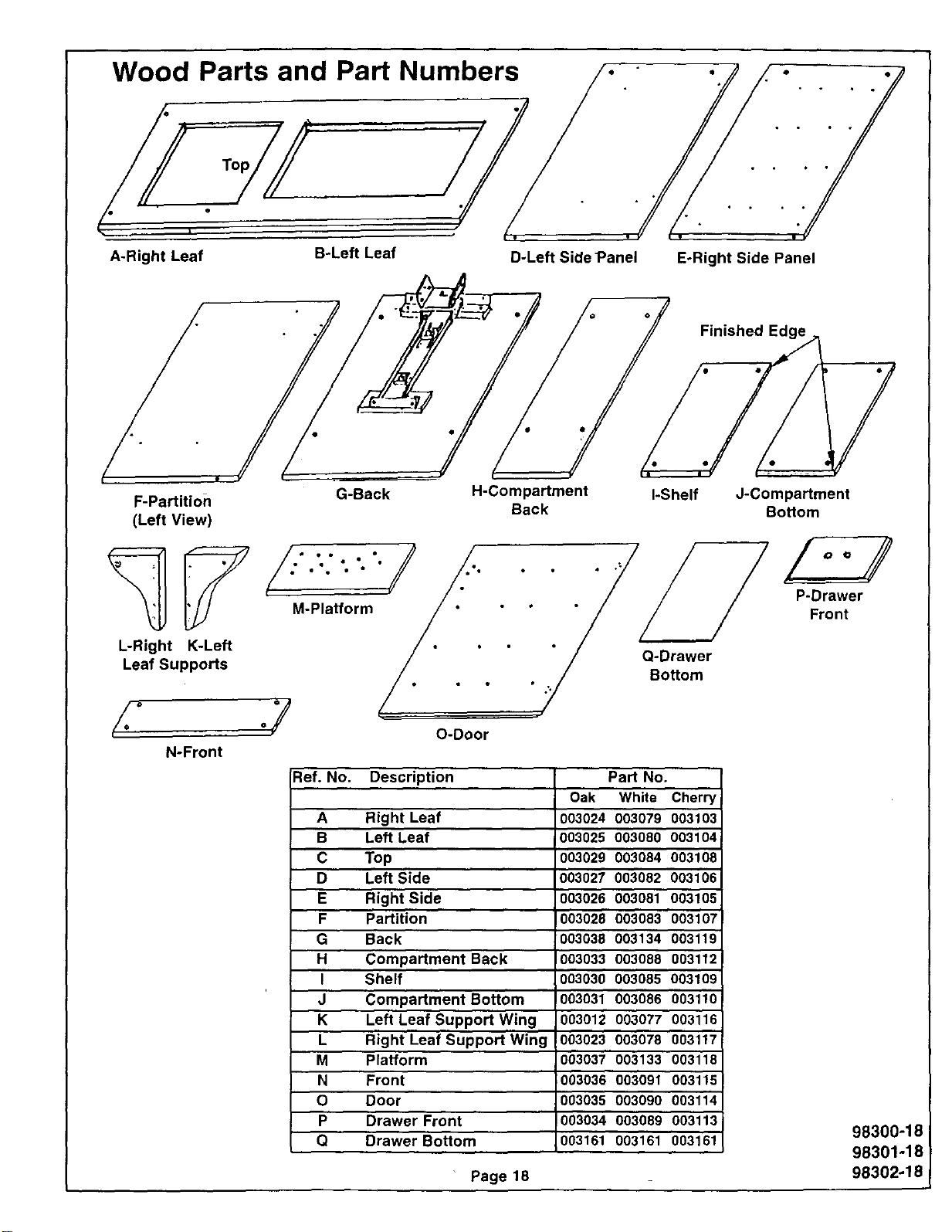
Wood Parts and Part Numbers
A-Right Leaf
B-Left Leaf
• _ " o o o
/
• " |°
D-Left Side Panel E-Right Side Panel
F-Partition
(Left View)
L-Right K-Left
Leaf Supports
G-Back
M-Platform
°y
H-Compartment I-Shelf
Back
Finished Edge
J-Compartment
Bottom
• . Bottom
O-Door
Ref. No. Description Part No.
Oak White Cherry
A Right Leaf )03024 003079 003103
B Left Leaf 003025 003080 0031'04
C Top 003029 003084 003106
D Left Side 003027 003082 003106
E Right Side 003026 003081 003105
F Partition 003028 003083 003107
G Back 003038 003134 003119
H Compartment Back 1003033 003088 003112
I Shelf 003030 003085 003109
J Compartment Bottom !003031 003086 003110
K Left Leaf Support Wing 003012 003077 0031'16
L Right Leaf Support Wing 003023 003078 003117
M Platform 003037 003'133 003118
N Front 003036 003091 003115
O Door 003035 003090 003114
P Drawer Front 003034 003089 003113
Q Drawer Bottom 003161 003161 003161
Page 18
P-Drawer
Front
98300-18
98301-18
98302_18!
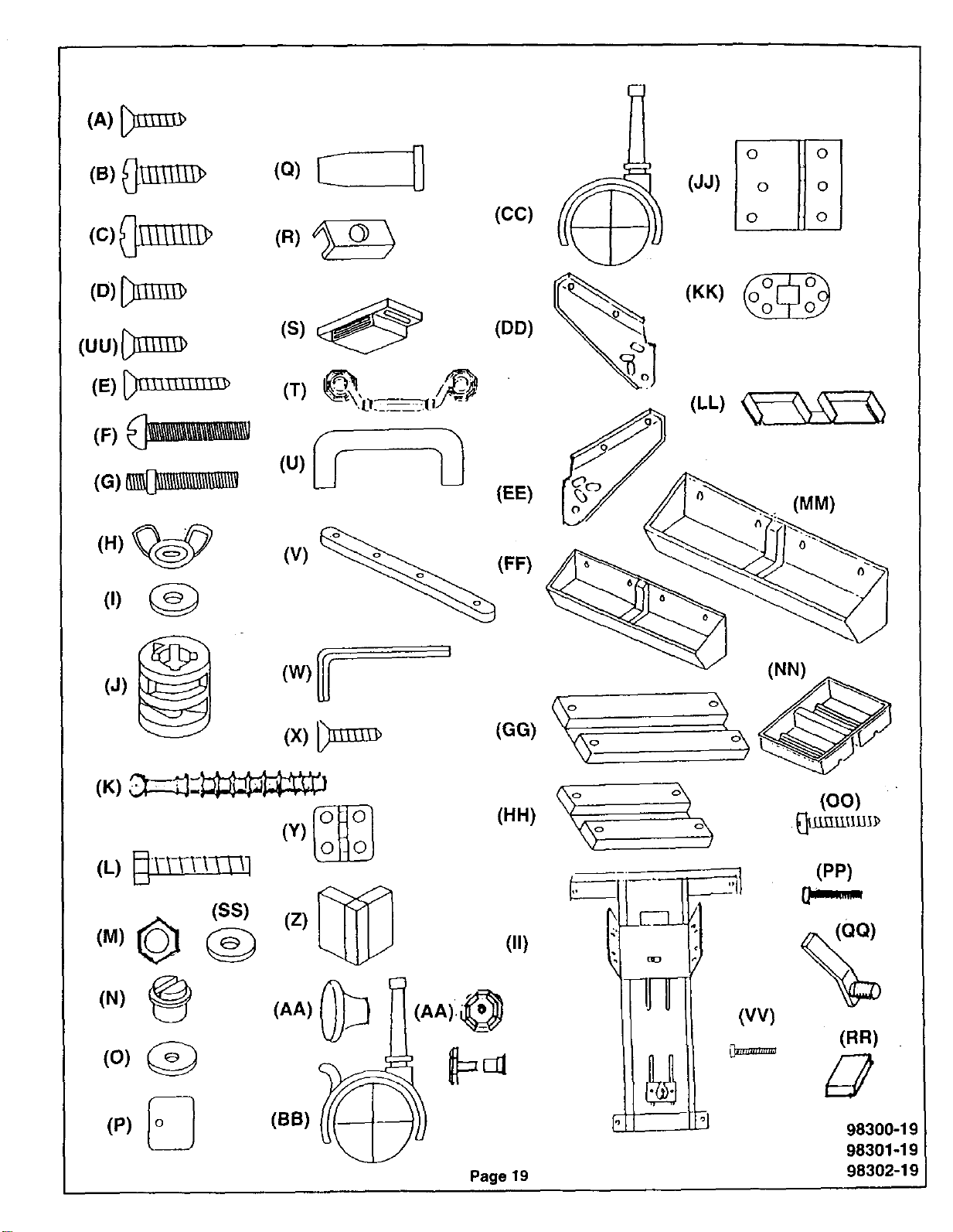
(cc)
(JJ)
I°ooijoloO
(uu){_
(E)
(F) __
(DD)
(EE)
(KK) (_
(LL)
(MM)
(H)_ (V)
(J)
(w)
(x)
(FF)
(L) __-__4-_1
(ss)
*)© @
(z)
(o) (_
(AA)
©
(p) _ (BB)
(11)
(AA).@
(oo)
(PP)
%
Page 19
(RR)
98300-19
98301-19
98302-19
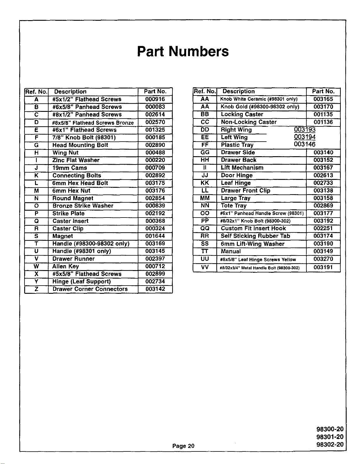
Part Numbers
Ref. No. Description Part No.
A #5xl/2" Flathead Screws 000916
B #6x5/8" Panhead Screws 000083
C #8xl/2" Panhead Screws 002614
D #8x5/8" Flathead Screws Bronze 002570
E #6x1" Flathead Screws 001325
F 7/8" Knob Bolt (98301) 000185
G Head Mounting Bolt 002890
H Wing Nut 000488
I Zinc Flat Washer 000220
J 19mm Cams 000709
K Connecting Bolts 002892
L 6mm Hex Head Bolt 003175
M 6mm Hex Nut 003176
N Round Magnet 002854
O Bronze Strike Washer 000839
P Strike Plate 002192
Q Caster Insert 000368
R Caster Clip 000324
S Magnet 001644
T Handle (#98300-98302 only) 003169
U Handle (#98301 only) 003145
V Drawer Runner 002397
W Allen Key 000712
X #5x5/8" Flathead Screws 002899
Y Hinge (Leaf Support) 002734
Z Drawer Corner Connectors 003142
_lef. No,
AA
AA
BB
CC
DD
EE
FF
GG
HH
II
JJ
KK
LL
MM
NN
OO
PP
QQ
RR
SS
1"1"
UU
VV
Description
Knob White Ceramic (#98301 only)
Knob Gold (#98300-98302 only)
Locking Caster
Non-Locking Caster
Right Wing
Left Wing
Plastic Tray
Drawer Side
Drawer Back
Lift Mechanism
Door Hinge
Leaf Hinge
Drawer Front Clip
Large Tray
Tote Tray
#6x1" Panhead Handle Screw (98301)
#8/32x1" Knob Bolt (98300-302)
Custom Fit Insert Hook
Self Sticking Rubber Tab
6mm Lift-Wing Washer
Manual
#8x5/8" Leaf Hinge Screws Yellow
#BI32x314" Metal Handle Bolt (98300-302)
Part No.
003165
003170
001135
001136
00393
003194
003146
003140
003152
003167
002613
002733
003138
003158
002869
003177
003192
002251
003174
003190
003149
003270
003191
Page 20
98300-20
98301-20
98302-20
API Specialty Furniture
(A Division of ARROW PRODUCTS, Inc.)
P.O. Box 410, Elkhorn, Wl 53121
1-800-533-7347
12-98
98300-BC
98301-BC
98302-BC