Loading ...
Loading ...
Loading ...
SECTION 3 - OPERATING INSTRUCTIONS
3.4 STARTING & OPERATING
(Continued from previous page)
13. STOPPING MACHINE,
Simultaneously squeeze both Traction Levers
firmly against the handle and hold. Pull both the
right and left Traction Locks rearward with index
fingers until both Traction Levers are locked in the
Traction Locked position.
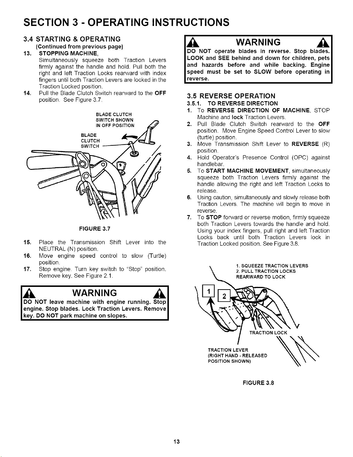
14. Pull the Blade Clutch Switch rearward to the OFF
position. See Figure 3.7.
BLADE CLUTCH
SWITCH SHOWN
IN OFF POSITION
SWITCH
FIGURE 3.7
15. Place the Transmission Shift Lever into the
NEUTRAL (N) position.
16. Move engine speed control to slow (Turtle)
position.
17. Stop engine. Turn key switch to "Stop" position.
Remove key. See Figure 2.1.
WARNING AI
DO NOT leave machine with engine running. Stop I
engine. Stop blades. Lock Traction Levers. Removel
key. DO NOT park machine on slopes.
WARNING
DO NOT operate blades in reverse. Stop blades.
LOOK and SEE behind and down for children, pets
and hazards before and while backing. Engine
speed must be set to SLOW before operating in
reverse.
3.5 REVERSE OPERATION
3.5.1. TO REVERSE DIRECTION
1. To REVERSE DIRECTION OF MACHINE, STOP
Machine and lock Traction Levers.
2. Pull Blade Clutch Switch rearward to the OFF
position. Move Engine Speed Control Lever to slow
(turtle) position.
3. Move Transmission Shift Lever to REVERSE (R)
position.
4. Hold Operator's Presence Control (OPC) against
handlebar.
5. To START MACHINE MOVEMENT, simultaneously
squeeze both Traction Levers firmly against the
handle allowing the right and left Traction Locks to
release.
6. Using caution, simultaneously and slowly release both
Traction Levers. The machine will begin to move in
reverse.
7. To STOP forward or reverse motion, firmly squeeze
both Traction Levers towards the handle and hold.
Using your index fingers, pull right and left Traction
Locks back until both Traction Levers lock in
Traction Locked position. See Figure 3.8.
\
1. SQUEEZE TRACTION LEVERS
2. PULL TRACTION LOCKS
REARWARD TO LOCK
TRACTION LOCK
TRACTION LEVER
(RIGHT HAND - RELEASED
POSITION SHOWN)
FIGURE 3.8
13
Loading ...
Loading ...
Loading ...