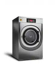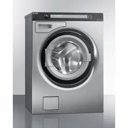

Service Manual Professional Washing Machine
Type: WM70.C

Service manual WM70.C
2

Type: WM70.C
Service manual
Contents
Updates ..................................................................................................................................................................................................................................................4
Introduction .........................................................................................................................................................................................................................................5
General product information.....................................................................................................................................................................................................6
Troubleshooting strategy ..............................................................................................................................................................................................................6
Panel .........................................................................................................................................................................................................................................................7
Knob and button descriptions ...................................................................................................................................................................................................7
LCD description ................................................................................................................................................................................................................................7
Settings....................................................................................................................................................................................................................................................8
Service menu ......................................................................................................................................................................................................................................9
Service menu content ................................................................................................................................................................................................................. 10
Notes for custom programmes ............................................................................................................................................................................................ 13
Making a custom programme .................................................................................................................................................................................................14
Program chart .................................................................................................................................................................................................................................15
Fault indicators ................................................................................................................................................................................................................................18
Components and measurement values ............................................................................................................................................................................ 19
Thermistor measurement values .......................................................................................................................................................................................... 20
Technical data ................................................................................................................................................................................................................................... 21
Tools ......................................................................................................................................................................................................................................................21
Wiring diagram ...............................................................................................................................................................................................................................22
Panel and control card replacement...................................................................................................................................................................................32
Wash agitator removal ...............................................................................................................................................................................................................34

Service manual WM70.C
4
Updates
Rev Date Description Initials
01 2010-07-12 First version developed BPA
02 2011-11-17 New document structur and updated wiring diagrams ISC
03 2012-04-20 Removed chapter General information, programme tables and added
reference to use the user manual.
BPA
04 2012-09-17 Updated with new version of circuit diagram 80 896 27 Ver01 BPA
05 2012-10-01 Added programme chart with new Allergy programmes BPA
Service manual WM70.C
5
WM 70.C
Introduction
You are holding the service manual for WM70.C washing machines.
It should be easy to service a washing machine. It is important that you, as a service technician,
are provided the necessary conditions to work in an efficient and satisfactory manner. Our hope is
that this service manual will prove a useful tool in your daily work.
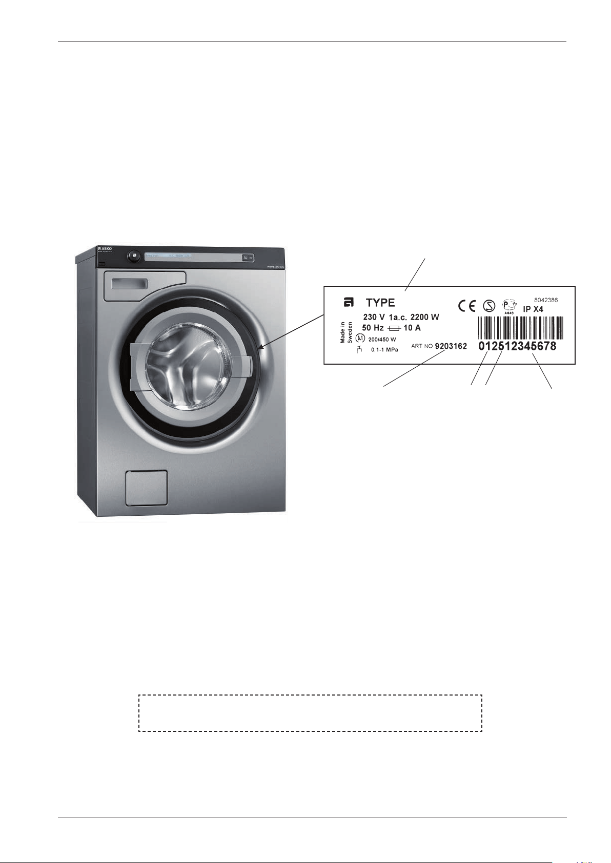
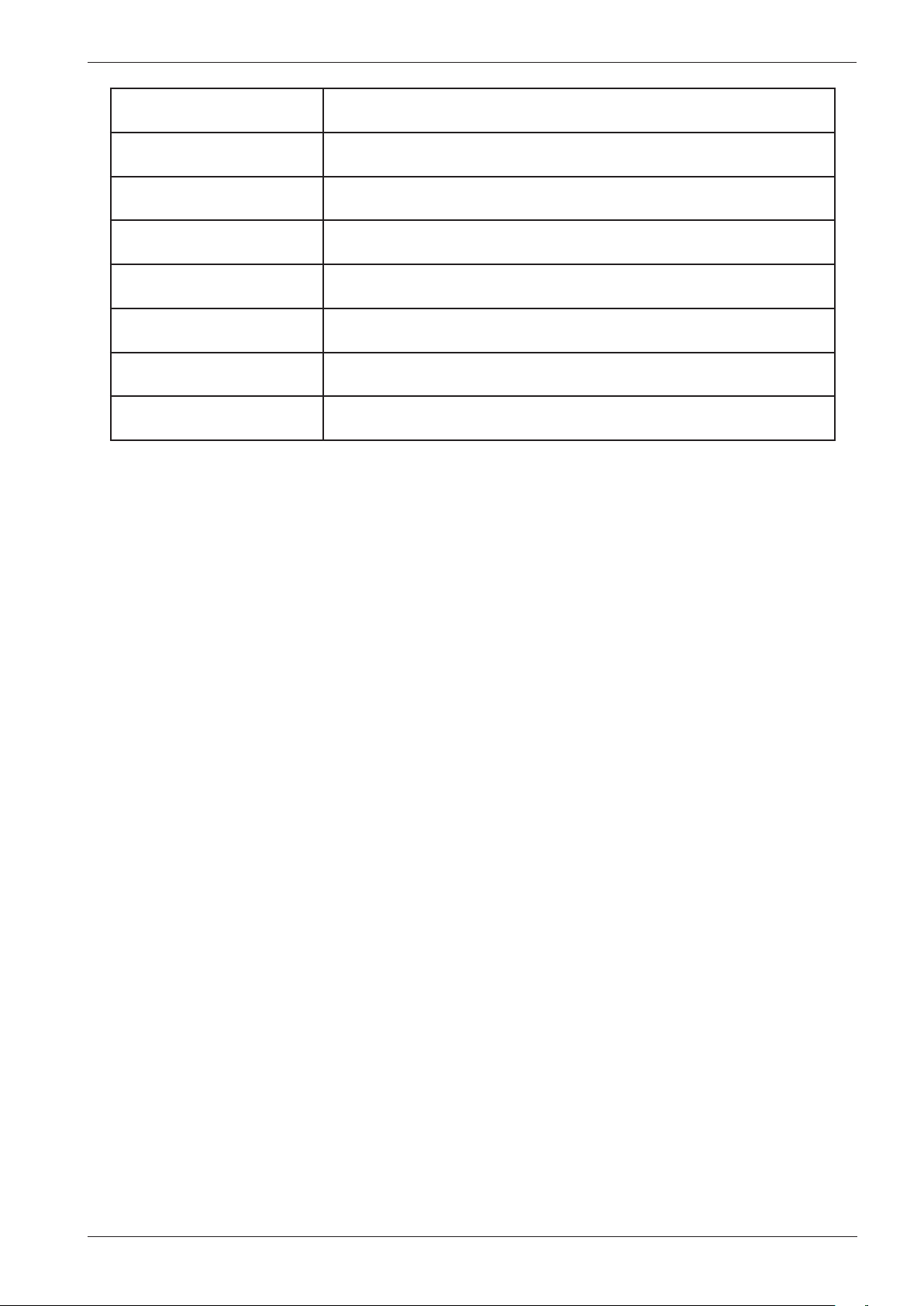
The type plate is located on the inside of the front door (see image below).
Asko Appliances AB
SE-534 82 Vara
Sweden
Type designation
Product number Serial number
Year
Week
BRUKSANVISNING
Ha alltid maskinens brukanvisning tillgänglig vid service
Service manual WM70.C
6
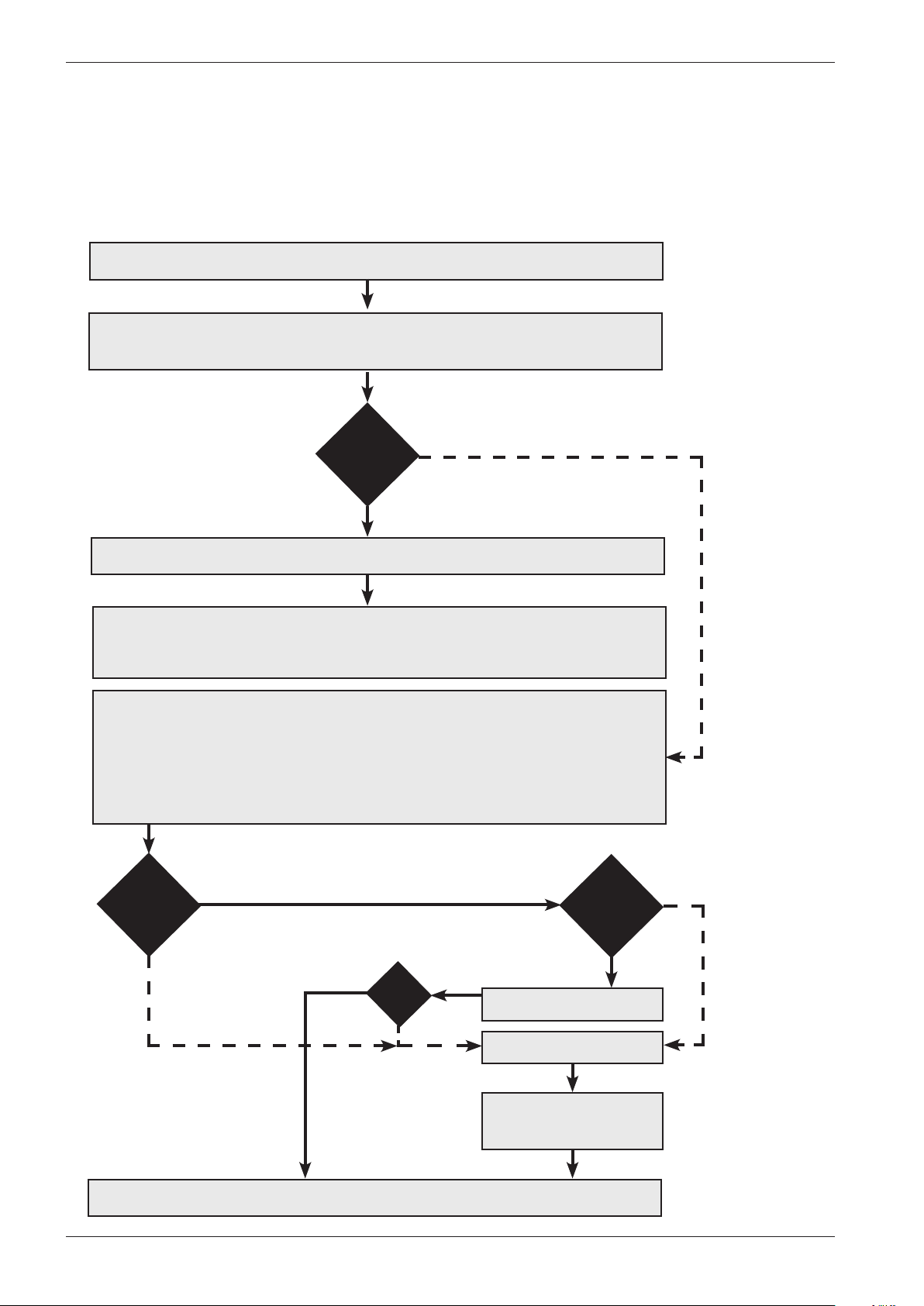
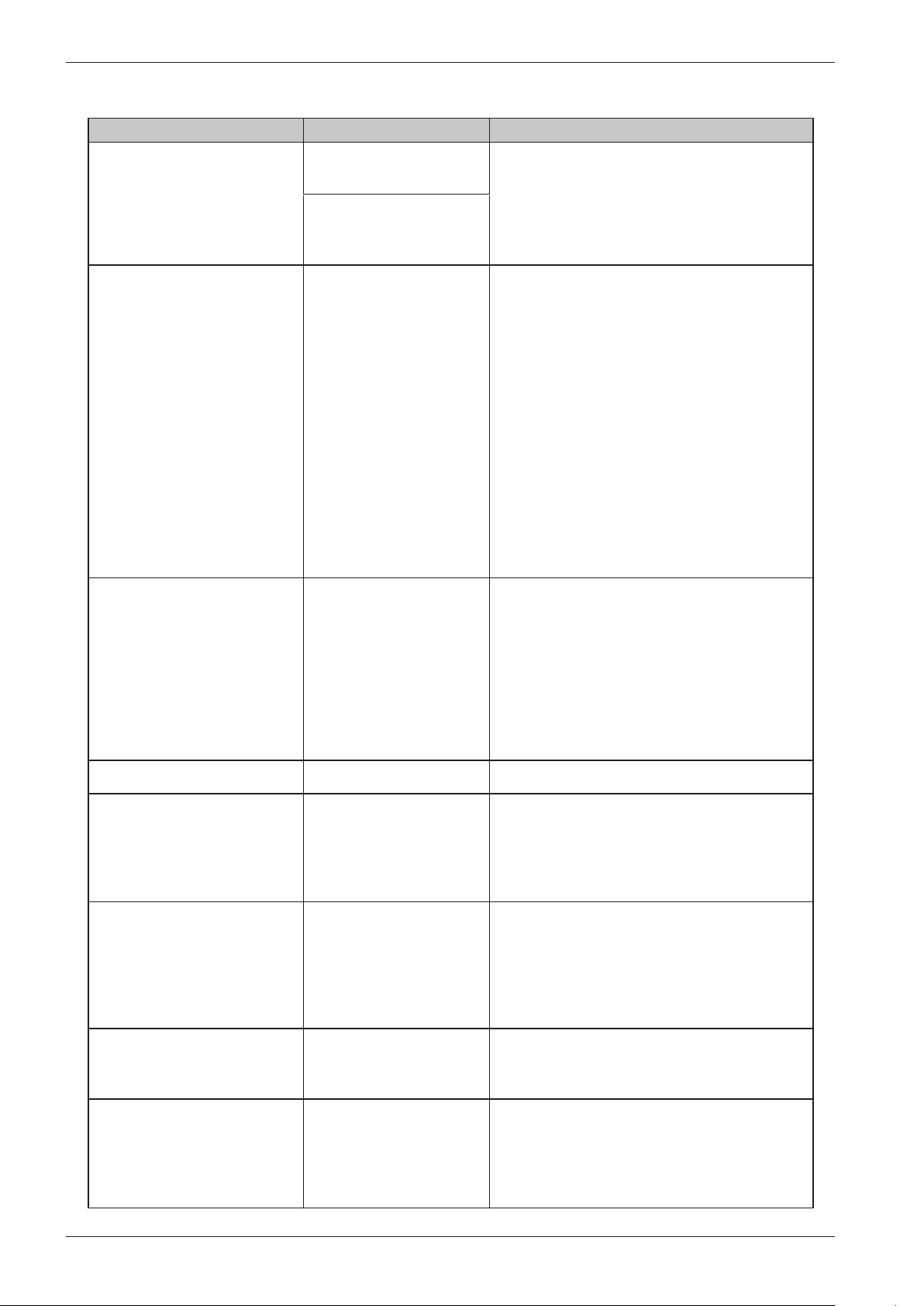
Troubleshooting strategy
At Asko, we believe in always remaining focused on the customer, and as an ASKO service
technician, you are one of the most important ambassadors of our brand. As such, it is important
that the customer finds the service callout a pleasant experience. Troubleshooting is an important
part of the service callout, and as such we have drawn up a troubleshooting strategy that
describes, in broad terms and step by step, what you need to do to find and diagnose faults.
• Ask the customer to describe the problem.
• Check whether the customer’s description matches any service code.
• Check that the machine is correctly installed:
- Electrical connection - Drainage
- Water connection - Machine correctly levelled
Fault found?
Incorrect installation or external factors that affect performance and functionality (for
example, water pressure, electrical supply, drainage).
The machine operates normally. No deviations can be found. The customer probably needs
to be informed about proper use of the machine. If necessary, also inform the customer
about the guarantee conditions and the fact that the customer will be charged for the
callout.
Yes
Open the service menu:
1. Check the settings
2. Run a test cycle
3. Note any fault codes
If the above actions do not uncover the fault:
• Conduct general troubleshooting. Use the documentation available at ServiceSaver
(service manuals, service memos, wiring diagrams and other documents).
Yes
No
Fault found?
No
Fault diagnosed?
Repair and check function/
safety.
Contact technical support
for assistance.
Carry out the actions
suggested by technical
support.
Satisfied customer!
OK?
No
Yes
No
Yes
Service manual WM70.C
7
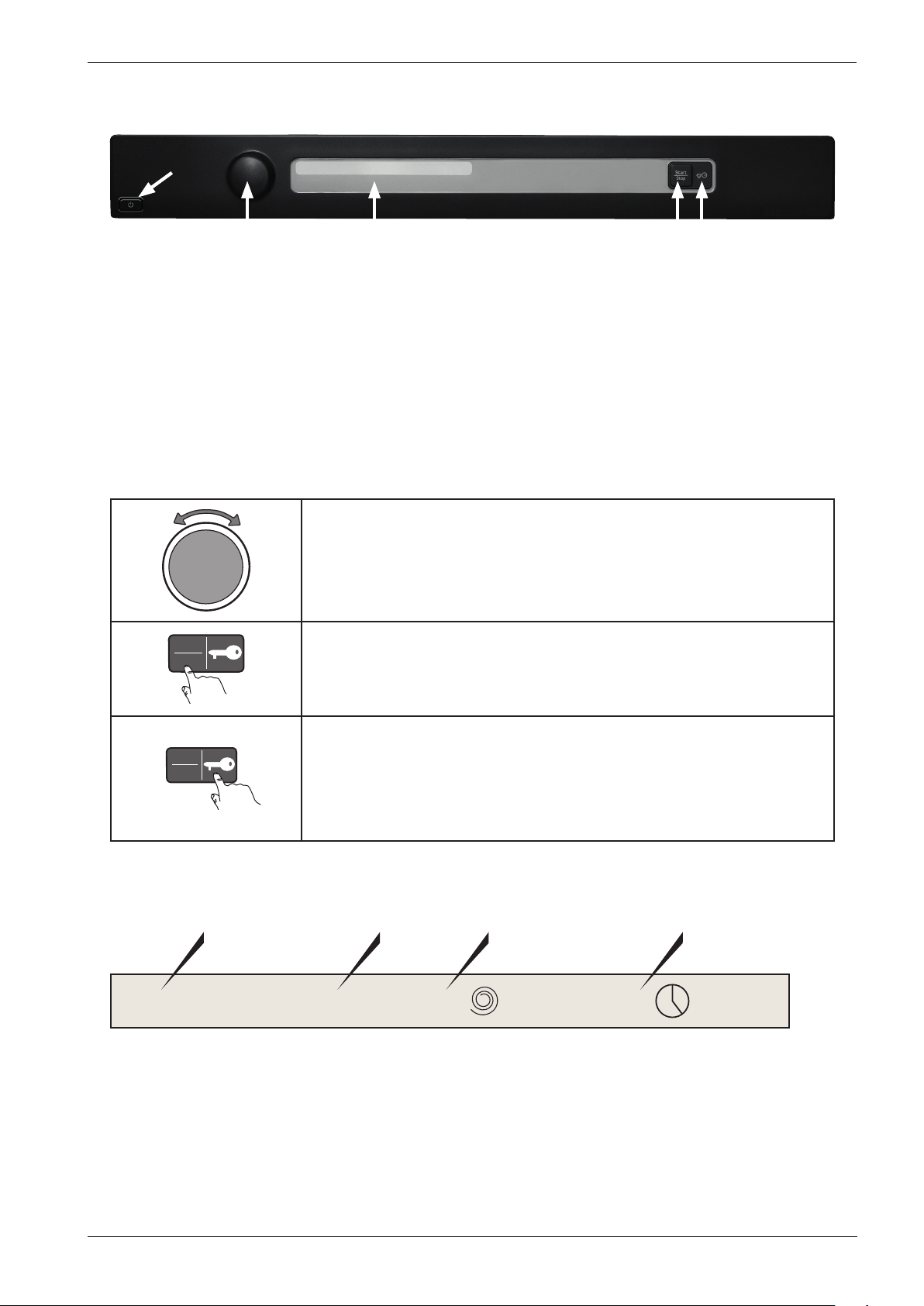
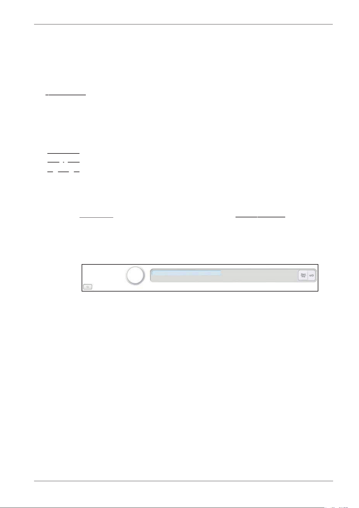
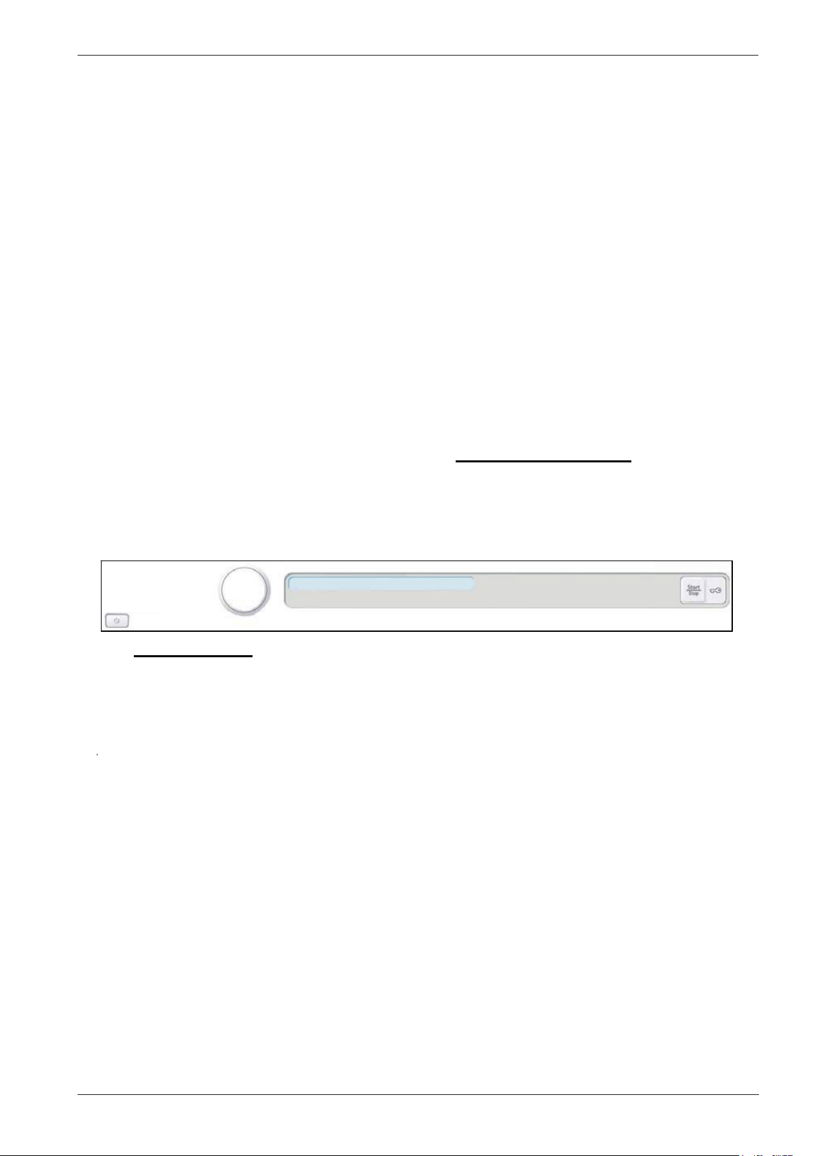
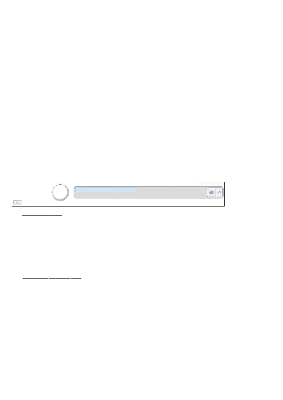
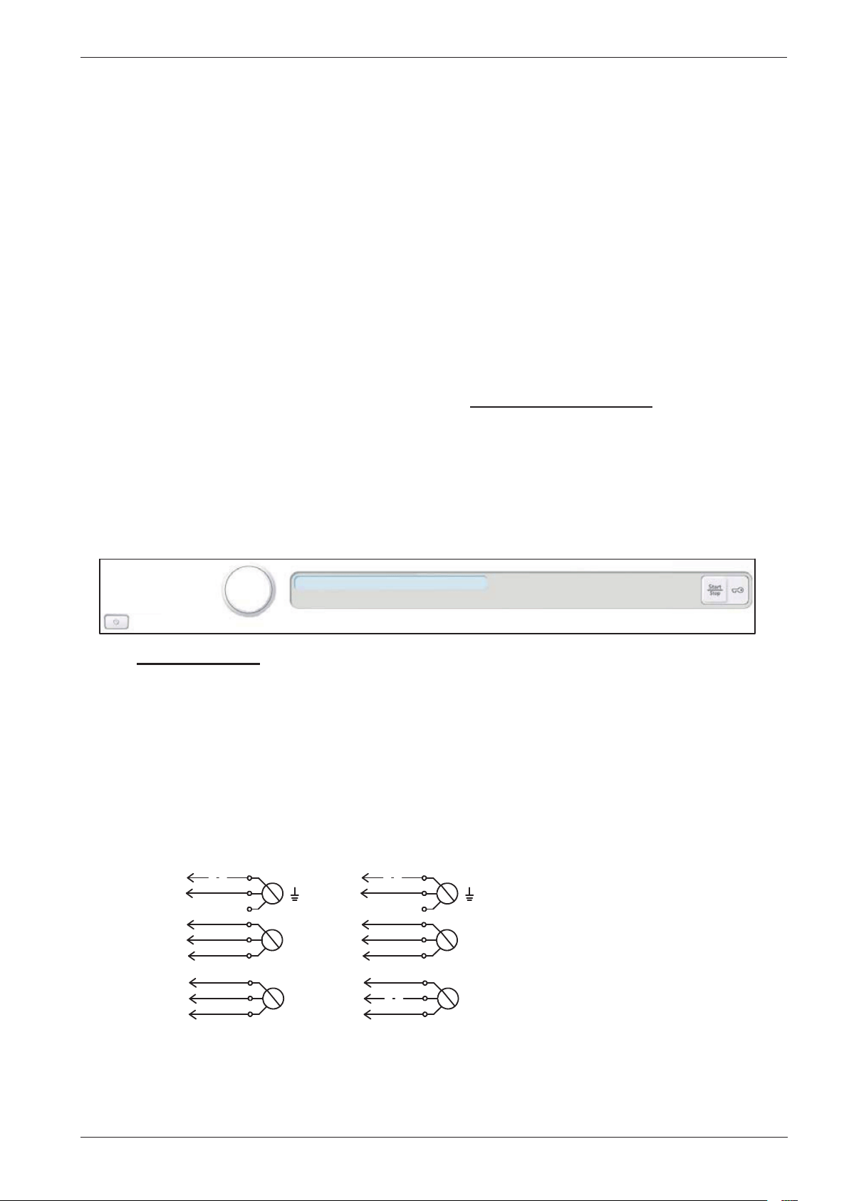
Panel WM70.C
Programmes: A total of twenty-two programmes, three of which can be customised via the
service menu. A maximum of ten programmes can be activated/available to the
end user at the same time.
Settings: Four (Language, Child-safe start, Automatic door opening, Temperature)
Knob and button descriptions
Programme selector
Turn clockwise or anti-clockwise to cycle through the different
programmes and options in the various menus.
Start
Stop
Start/Stop button
• Start programme
• Stop programme. Press and hold for 3 seconds.
Start
Stop
Key button
• Opens the door once the programme has ended.
• Opens the door during a programme to add more laundry.
• Confirm selection in the settings and service menus.
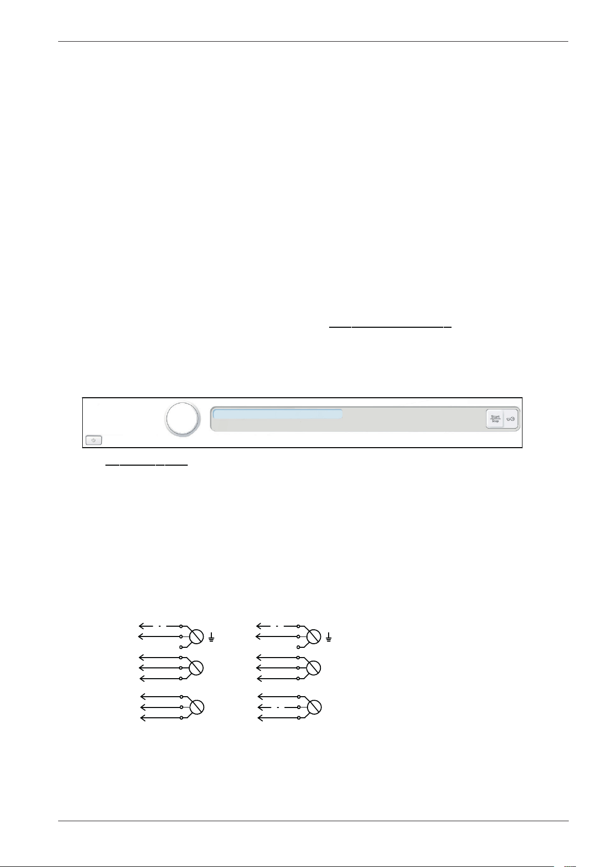
LCD description
Normal wash 60°C 1600 2:20
Programme name
Temperature
Spin speed
Estimated
remaining time
J1
LCD
S4
S5
S1
Service manual WM70.C
8
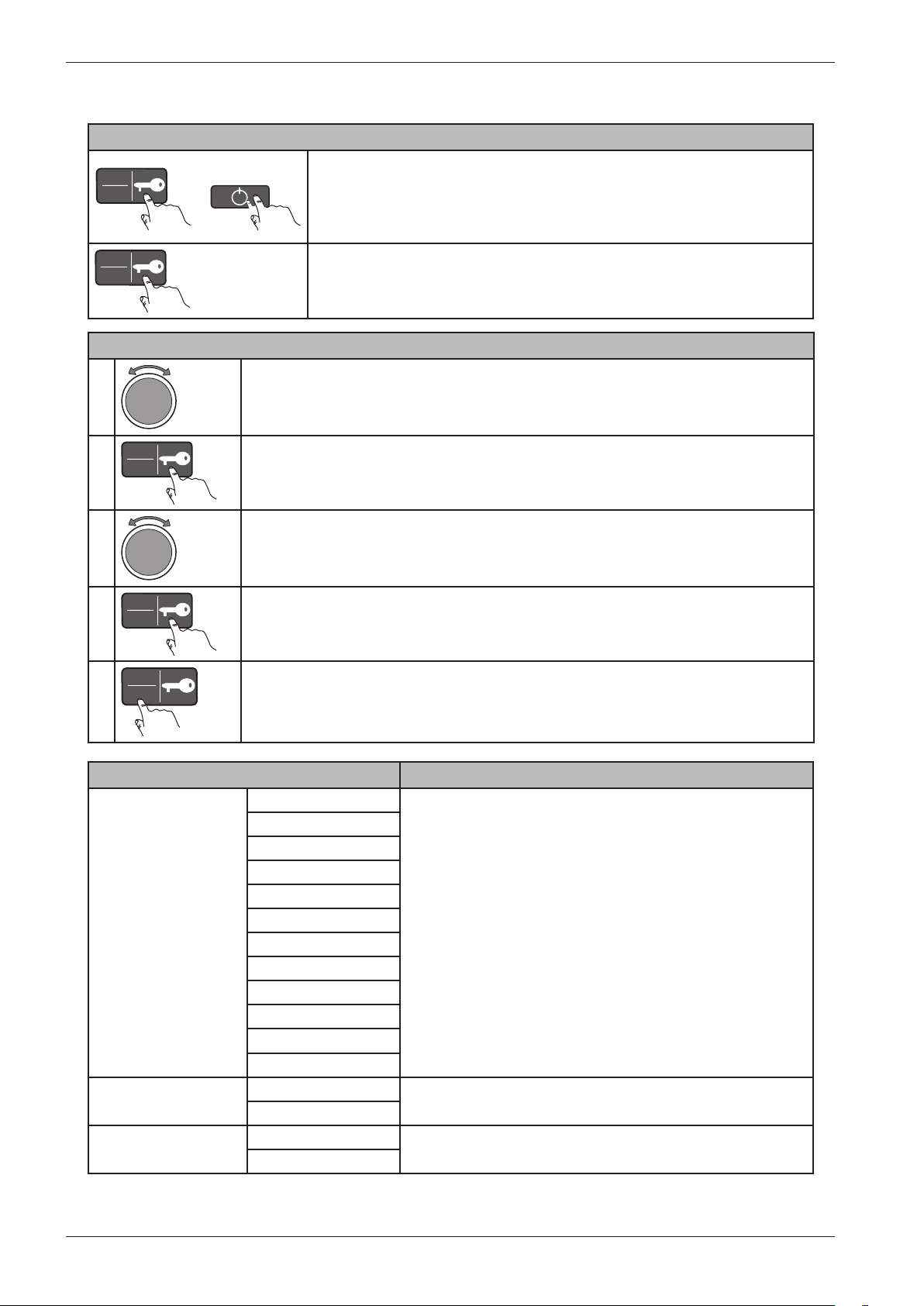
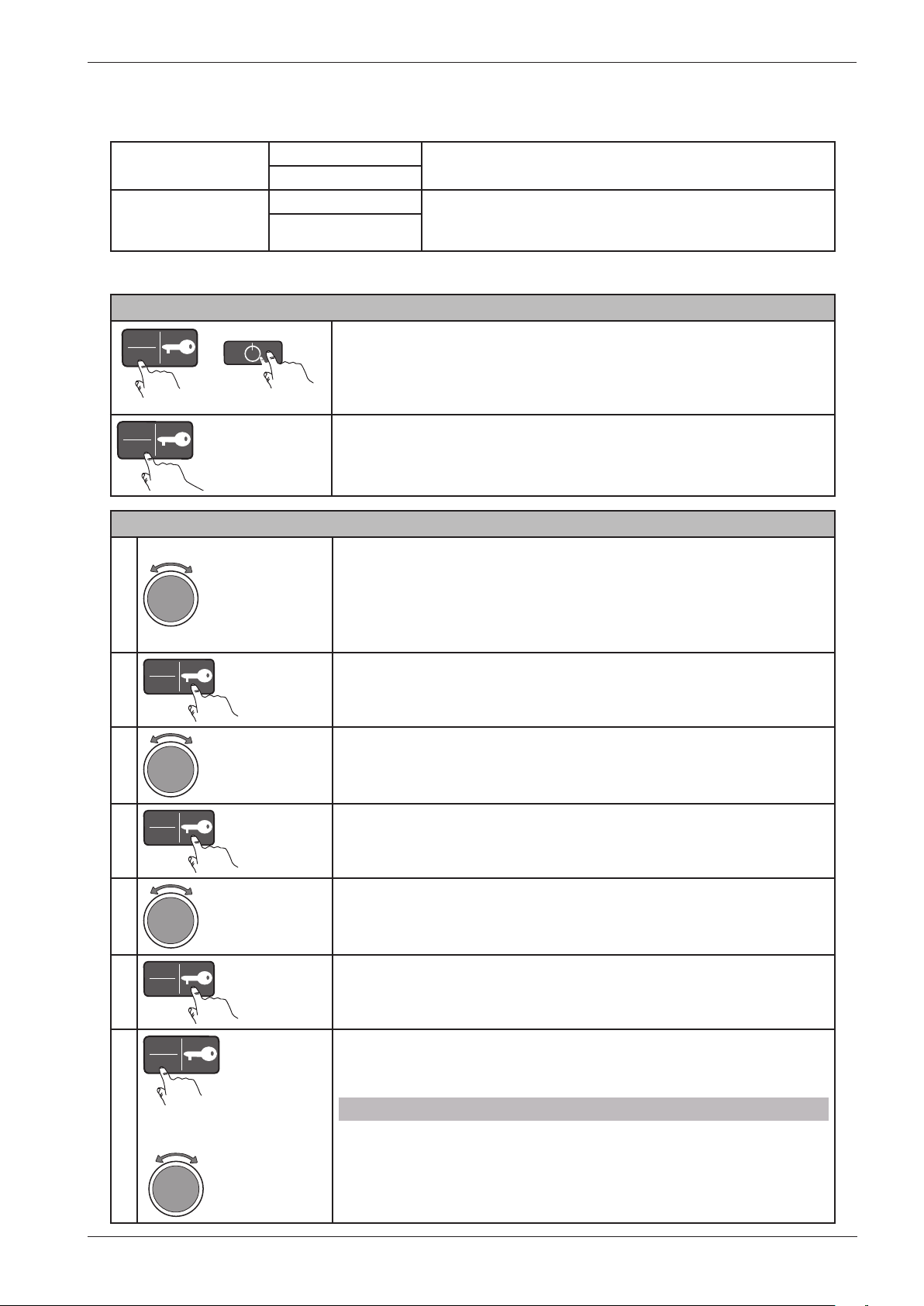
Settings
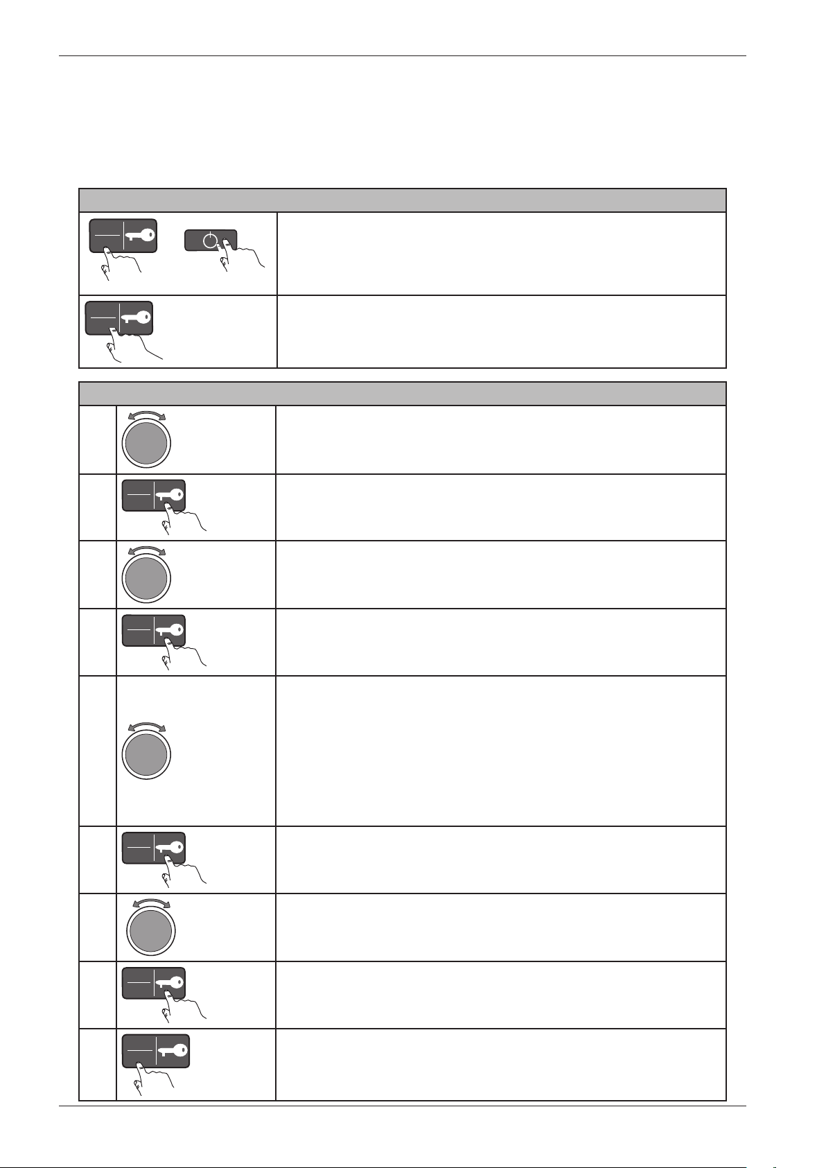
Opening the settings menu
Start
Stop
+
På/Av
Is the machine on? First turn off the power at the main power
switch (S1).
Press and hold the Key button (S5) while simultaneously pressing
the main power switch (S1).
Start
Stop
5X
Press the Key button (S5) 5 times within 10 seconds. The settings
menu now opens.
Service menu content Comments
Language US English Note: The language used under “Special” in the service menu is
not changed (English only).
English
Svenska
Dansk
Norsk
Suomi
Français
Deutsch
Italiano
Espanol
Русский
Nederlands
Child-safe Child-safe Off You can temporarily disable Child-safe start by pressing
the Start/Stop button and the Key button simultaneously.
Child-safe On
Door opening Door opening Off
Door opening On
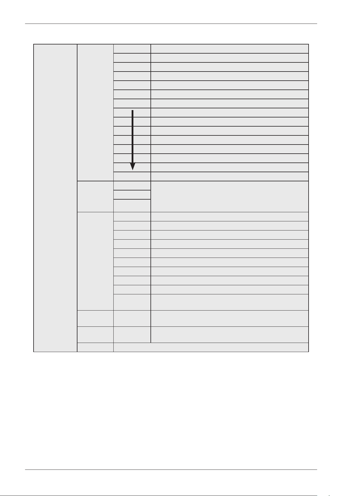
Choosing a setting (an example)
1
Turn the programme selector (J1) to cycle through the settings menu
options.
2
Start
Stop
Press the Key button (S5) to select an item in the settings menu.
3
Turn the programme selector (J1) to cycle through the different options for
that setting.
4
Start
Stop
Press the Key button (S5) to select one of the settings.
5
Start
Stop
Press the Start/Stop button (S4) to save the settings and return to the
programme menu.
Continous ...
Service manual WM70.C
9
Service menu
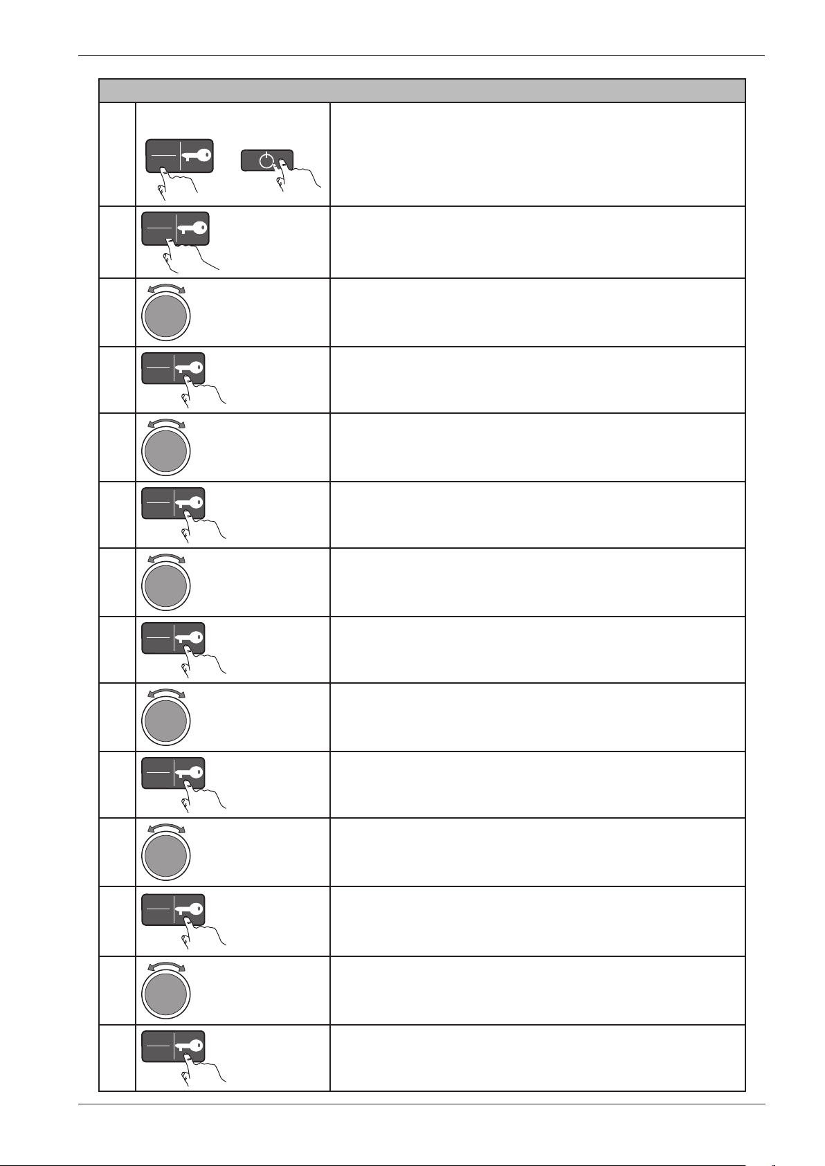
Navigating the service menu
1
Turn the programme selector (J1) to cycle through the different
service menu options.
- 1 Service
- 2 Settings
- 3 Special
2
Start
Stop
Press the Key button (S5) to select an option in the service menu.
3
Turn the programme selector (J1) to cycle through the different
settings.
4
Start
Stop
Press the Key button (S5) to select a setting.
5
Turn the programme selector (J1) to select one of the options.
6
Start
Stop
Press the Key button (S5) to confirm/save or go back one step.
7
Start
Stop
or
Press the Start/Stop button (S4) to return to the programme
menu or use the programme selector to make additional choices.
NB:
The different options in the service menu vary in terms of the
number of alternative selections and settings.
Opening the service menu
Start
Stop
+
På/Av
If the machine is on: First turn off the power at the main power
switch (S1).
Press and hold the Start/Stop button (S4) while simultaneously
pressing the main power switch (S1).
Start
Stop
× 5
Press the Start/Stop button (S4) 5 times within 5 seconds. The
service menu now opens.
°C/°F °C
°F
Water inlet Cold Valid for products manufactured from February, 2012. For
products manufactured before February 2012, see service menu
setting 21.
Hot
... continous
Service manual WM70.C
10
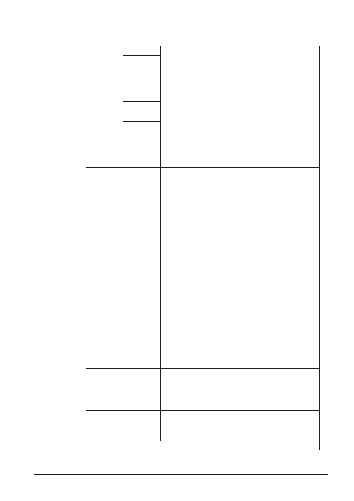
1 Service 11 Info SP: XXXX Date the software was programmed (Year_Week)
CM: XXXX Date of manufacture of the control unit (Year_Week)
SW: Software version
SW: Software version
NC: Number of cycles/programmes run
NC 1: Number of cycles for Programme 1
NC 2: Number of cycles for Programme 2
NC 28: Number of cycles for Programme 28
12 Fault
scenarios
Fault 1 Shows current fault. The display shows Fault name_Programme
number_Number of cycles_ Index number.
Example: Thermistor fault_Pr5_9_(1)
Fault 2
Fault 3
13
Diagnostics
Test
Test valve 1 Inlet valve 1 is open.
Test valve 2 Inlet valve 2 is open.
Test valve SM Inlet valve 1 and 2 are open.
Test valve 3 Inlet valve 3 is open.
Test heater Heater on up to max. 60°C.
Test motor The motor normally runs at 49 rpm.
Test drain The drainage pump runs.
Test spin The machine runs a spin sequence, the drainage pump runs.
Test door The door lock is activated and the door opens. Returns to the
programme menu.
14 Total
reset
The machine is restored to its factory settings. Returns to the
programme menu after Total reset.
15 ABC
reset
The custom programmes (Pr20-Pr22) are reset. Returns to the
programme menu after ABC reset.
Return Press the Key button (S5) to return to 1 Service.
Service menu content
Service manual WM70.C
11
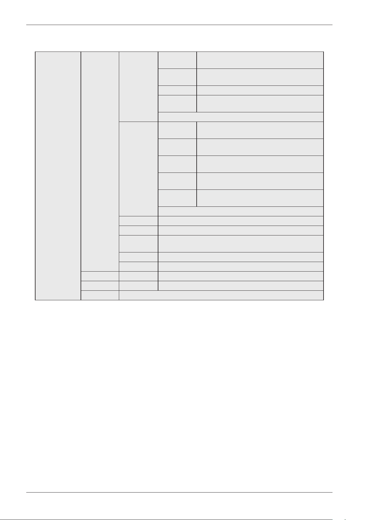
2 Settings 21 Water
inlet
Cold Valid for products manufactured before February 2012.
Hot
21 HWC Off (default) Valid for products manufactured from February 2012.
On
22 Max RPM 400 rpm This function only works for programmes Pr1-Pr19.
600 rpm
800 rpm
1000 rpm
1200 rpm
1300 rpm
1400 rpm
1500 rpm
1600 rpm
23 Drain Pump
Valve
24 Show
temp
Temp Off Only applies to the disinfection programmes (Pr17-Pr19)
Temp On
25 Change
temp
Pr1-Pr25 This can be changed in steps of 1°C between -10°C to +10°C.
You cannot set a total temperature that exceeds +92°C.
26 Programs Pr1-Pr28 Select “On” or “Off”
Programmes can be activated/deactivated. A deactivated
programme is not shown on the display.
A maximum of 10 programmes can be shown on the display in
programme mode. If more than 10 programmes are activated,
then only the first ten activated programmes are shown on the
display.
If all the programmes have been deactivated, the display only
shows “Pr1”.
If the machine is Swan-labelled, “Pr1” and “Pr2” are always
activated/On.
27 Spin time 0-300 sec • Extend or shorten the spin time: 0-300 sec.
• If “0 sec” is selected, the pre-programmed spin time is used.
• If a time in the interval “1 sec” to “300 sec” is selected, this
time is added to the pre-programmed spin time.
• This function only works for programmes Pr13 and Pr14.
28 Coin Coin Off See the wiring diagram for the correct connection and
functionality of a slot meter.
Coin On
29 Reset Only
production
reset
Used only in production
210 Off (default) When On is choosed it shall be possible to temporally change
to language in the machine. The language shall return to selected
machine language (selected in the user menu) when the
program is finished. This menu step is placed after program 28.
On
Return Press the Key button (S5) to return to 2 Settings.
Service menu content (cont.)
Service manual WM70.C
12
3 Special Pr 26 34 Pre wash 341 Number
of
0/1/2/3
342 Water
level
Normal water level/High water level
343 Time 1/2/3/4/...../15 (min)
344 Heat
temp
No heat/25°C/26°C/......./60°C
Return
35 Main wash 351
Temperature
30°C/31°C/...../92°C
352 Water
level
Normal water level/High water level
353 Reheat
temp
28°C/29°C/...../90°C
354 Reheat
time
0min/1min/...../60°C
355 Work
time
0min/1min/...../60min
Return
36 Rinses 1 Rinse/2 Rinse/...../7 Rinses
37 Extra spin On/off
38 Spin
speed
400/600/800/1000/1200/1300/1400/1500/1600 RPM
39 Spin time 0-300 sec
Return Press the Key button to return to the previous menu level.
Pr 27 See above
Pr 28 See above
Return Press the Key button (S5) to return to 3 Special.
Service menu content (cont.)
Service manual WM70.C
13
Notes
Pr 26
34 Pre
wash
341 Number of
342 Water level
343 Time
344 Heat temp
35 Main
wash
351 Temperature
352 Water level
353 Reheat temp
354 Reheat time
355 Work time
36 Rinses
37 Extra spin
38 Spin speed
39 Spin time
Pr 27
34 Pre
wash
341 Number of
342 Water level
343 Time
344 Heat temp
35 Main
wash
351 Temperature
352 Water level
353 Reheat temp
354 Reheat time
355 Work time
36 Rinses
37 Extra spin
38 Spin speed
39 Spin time
Pr 28
34 Pre
wash
341 Number of
342 Water level
343 Time
344 Heat temp
35 Main wash 351 Temperature
352 Water level
353 Reheat temp
354 Reheat time
355 Work time
36 Rinses
37 Extra spin
38 Spin speed
39 Spin time
Notes for custom programmes
Save these notes for
future reference!
Make a note of the settings you make when creating custom programmes (Pr20, 21, 22).
Save this note close to the machine
Service manual WM70.C
14
Making a custom programme
Programming
1
Turn the programme selector (J1) to “3 Special”.
2
Start
Stop
Press the Key button (S5) to open the “3 Special” menu.
3
Turn the programme selector (J1) to cycle through the different
options: Pr20, Pr21, Pr22 and Return.
4
Start
Stop
Press the Key button (S5) to open one of the options, Pr20, Pr21
or Pr22. Now you can create your programme by selecting from
the various options and settings.
5
Turn the programme selector (J1) to cycle through the different menus:
-34 Pre wash
-35 Main wash
-36 Rinses
-37 Extra spin
-38 Spin speed
-39 Spin time
Return
6
Start
Stop
Press the Key button to open one of the menus.
7
Turn the programme selector (J1) to cycle through the different
menu options.
8
Start
Stop
Press the Key button to save the setting and return to the
previous menu level. Repeat steps 5 to 8 to program the
remaining settings.
9
Start
Stop
Once you have finished creating the programme, press the Start/
Stop button (S4) to return to the programme menu.
Opening the service menu
Start
Stop
+
På/Av
If the machine is on: First turn off the power at the main power
switch (S1).
Press and hold the Start/Stop button (S4) while simultaneously
pressing the main power switch (S1).
Start
Stop
× 5
Press the Start/Stop button (S4) 5 times within 5 seconds. The
service menu now opens.
You can make three custom programmes. This is done in the service menu. In order for the new
programme to be made available, one of the existing programmes must be deactivated, that is, set
to “Off”, and the new programme set to “On”. See also the “3 Special” section of the “Service
menu content” chapter.
Service manual WM70.C
15
Activate the new programme
1
Start
Stop
+
På/Av
If the machine is on: First turn off the power at the main
power switch (S1).
Press and hold the Start/Stop button (S4) while
simultaneously pressing the main power switch (S1).
2
Start
Stop
× 5
Press the Start/Stop button (S4) 5 times within 5 seconds.
The service menu now opens.
3
Turn the programme selector (J1) to “2 Settings”.
4
Start
Stop
Press the Key button (S5) to open the “2 Settings” menu.
5
Turn the programme selector (J1) to “26 Programs”.
6
Start
Stop
Press the Key button (S5) to open the “26 Programs” menu.
7
Turn the programme selector (J1) to select the programme
you want to deactivate.
8
Start
Stop
Press the Key button to open the menu.
9
Turn the programme selector to “Off” to deactivate the
programme.
10
Start
Stop
Press the Key button (S5) to confirm/save.
11
Activate your new programme by turning the programme
selector to the programme you want to activate.
12
Start
Stop
Press the Key button to open the menu.
13
Turn the programme selector to “On” to activate the
programme.
14
Start
Stop
Press the Key button to confirm/save.
Service manual WM70.C
16
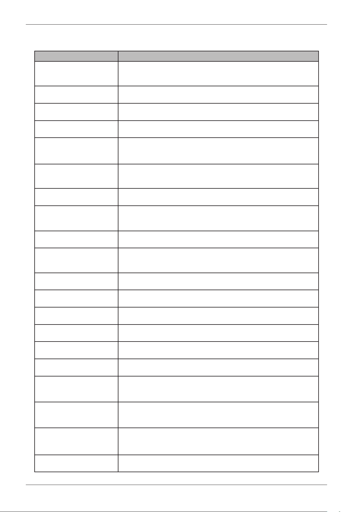
Programme name Description
1. Normal wash (USA: Normal
Hot) 60°C
Programme for normally to heavily soiled laundry, whites and colours. Follow
the washing instructions for each garment. 60°C is a good temperature for
garments worn next to the skin. This programme has five rinses.
2. Normal wash (USA: Normal
Warm) 40°C
Programme for normally to heavily soiled laundry, whites and colours. Follow
the washing instructions for each garment. This programme has five rinses.
3. Heavy wash 90°C Programme for heavily soiled laundry, with dirt that needs to be fully dissolved
before the main wash. A pre-wash is used to do this.
4. Heavy wash 60°C Programme for heavily soiled laundry, with dirt that needs to be fully dissolved
before the main wash. A pre-wash is used to do this.
5. White (USA: Sani) 90°C Programme for normally to heavily soiled laundry. Follow the washing
instructions for each garment. 90°C is a good temperature for white and light-
coloured cotton, such as bed linen.
6. White/Colour (USA: White)
60°C
Programme for normally soiled laundry, whites and colours. Follow the washing
instructions for each garment. 60°C is a good temperature for garments worn
next to the skin.
7. White/Colour (USA: Colour)
40°C
Programme for normally soiled laundry, whites and colours. Follow the washing
instructions for each garment.
8. Super quick wash (USA:
Quick wash) 60°C
Fast programme for laundry that just needs freshening up. Follow the washing
instructions for each garment. Garments worn next to the skin ought to be
washed at 60°C.
9. Super quick wash 40°C Fast programme for laundry that just needs freshening up. Follow the washing
instructions for each garment.
10. Synthetics (USA:
PermaPress) 40 °C
Programme for synthetics, delicate blended materials and permanent press
cotton. Suitable for shirts and blouses. Follow the washing instructions for each
garment. Many synthetics will come clean at 40°C.
11. Wool/hand wash 30°C A gentle laundry programme for wool, silk and garments that should be washed
by hand. This programme has a short spin.
12. Rinse This programme performs one cold rinse cycle + spin. Suitable for laundry that
just needs to be dampened.
13. MOP wash 60°C Programme suitable for different types of mop. The programme has two rinses
using much water.
14. MOP wash 90°C Programme suitable for different types of mop. The programme has two rinses
using much water.
15. Micro fibre wash 60°C Programme for laundry made of micro fibres, such as micro-fibre cloths. The
programme has three rinses with much water in the first rinse.
16. Micro fibre wash 40°C Programme for laundry made of micro fibres, such as micro-fibre cloths. The
programme has three rinses with much water in the first rinse.
17. Disinfection 40°C Programme where the temperature reached during the main wash is
maintained for 20 minutes. Disinfection at this temperature requires special
detergent.
18. Disinfection 60°C Programme where the temperature reached during the main wash is
maintained for 20 minutes. Disinfection at this temperature requires special
detergent.
19. Disinfection 90°C Programme where the temperature reached during the main wash is
maintained for 10 minutes. This temperature is sufficient for disinfection without
special detergent.
20. Allergy cotton 90°C
Programmes
Service manual WM70.C
17
21. Allergy cotton 60°C
22. Allergy cotton 40°C
23. Allergy synthetic 60°C
24. Allergy synthetic 40°C
25. Cleaning
26. Program 26 Programmable
27. Program 27 Programmable
28. Program 28 Programmable
Service manual WM70.C
18
Fault indicators
Error message Cause Action
Over flow fault Too much water in the
machine.
Service action:
Check the machine's level system, inlet valve and
drainage pump. Check for any leaks.
The drainage pump is
running but the machine is
empty.
Water outlet fault • The drainage pump has
been running for 3 minutes.
Water remains in the
machine.
• The wash cycle
is stopped and the
programme is reset.
1. Check that nothing is stuck in the drainage hose
outlet.
2. Check that the drainage pump is not blocked
by foreign objects.
3. Check that there are no kinks in the drainage
hose.
Service action:
1. If the pump only runs for a short while
(approximately 20 seconds), this indicates a fault
in the level system. Check the level sensor and
hoses.
2. Check the wiring and voltage to the pump. If
necessary, replace the pump and/or control unit.
3. After taking corrective action, run the Drain
programme or press the Key (door opening)
button to empty the machine.
Water inlet fault If the correct water level
is not achieved within five
minutes the wash cycle will
be stopped.
1. Check that the tap on the water pipe is open.
Service action:
1. Check that the filter in the machine's water
intake is not blocked.
2. Check the inlet valve. If necessary, replace the
valve.
3. Check the voltage to the inlet valve. If there is
no voltage, this could be due to a fault in the level
system, wiring or control unit.
Security fault The door is open Close the door
Thermistor fault 1. Thermistor circuit open
2. Thermistor malfunction
3. The measurement value
for the thermistor is <300
Ω (>120°C)
Service action:
Check the thermistor. Replace if necessary.
Temperature fault The temperature has
increased < 5°C in ten
minutes
The wash cycle should
continue to the next step
of the programme.
Service action:
Check the thermistor, heater, wiring and level
system.
Wash motor fault No signal from the tacho
or MCU.
Service action:
Check the output signal from the MCU and the
wiring between the motor and the MCU.
Pressure fault Indicated if the level drops
to zero within 30 seconds
of the first rinse.
Service action:
Check for leaks.
Service manual WM70.C
19
Components and measurement values
Item
number
Component Measurement value Comment
80 658 33 CIM motor Resistances:
Pins 1-3 stator 3.7 Ω
Pins 1-2 stator 3.6 Ω
Pins 2-3 rotor 3.6 Ω
Pins 4-5 tacho 178 Ω
80 617 03
80 617 04
Heating element 2000
W
Heating element 1000
W
80 761 02 Thermistor 6.1–3.8 kΩ (at room
temperature 20–30°C)
The thermistor for measuring temperature
is located between the motor cradle and the
drum. The thermistor measures and controls
the water temperature, which can vary from
0 to 92°C. The heater is disconnected if the
thermistor is short-circuited or disconnected
from the programme control card.
88 012 63 Drainage pump 50 Hz 144 Ω The drainage pump is combined with an
integrated fine filter trap, which can be cleaned
by the user. If the drainage pump has run for 3
minutes during draining, the programme stops,
resets and a fault code is indicated on the display.
The pump has a capacity of 20 litres/minute.
88 012 64 Drainage pump 60 Hz 76 Ω
80 782 21 Level switch Electromechanical level switch with two levels
(see wiring diagram). Used to indicate levels for
door opening, heat and overflow.
80 762 02 EMC filter 50/60 Hz 680 Ω The filter eliminates interference to and from
the machine.
80 793 24 Inlet valve 3.7 kΩ ± 0.5 kΩ Two-way inlet valve, 8 litres/minute
80 798 73 Door lock 122 Ω The door lock is electromechanical and
equipped with a magnet.
80 833 15 One-way inlet valve
80 818 07 Motor control
80 806 28 Control unit
80 833 43 Communication unit
80 083 65 Outlet valve
Service manual WM70.C
20
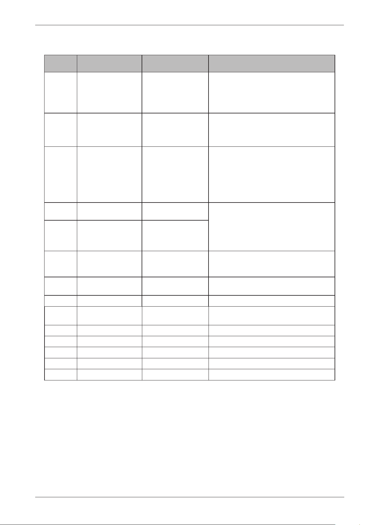
Temp, ºC Resistance, ohm
0 15806
10 9634
20 6046
25 4841
30 3900
40 2579
50 1744
60 1204
70 848
80 609
85 519
Thermistor measurement values
Service manual WM70.C
21
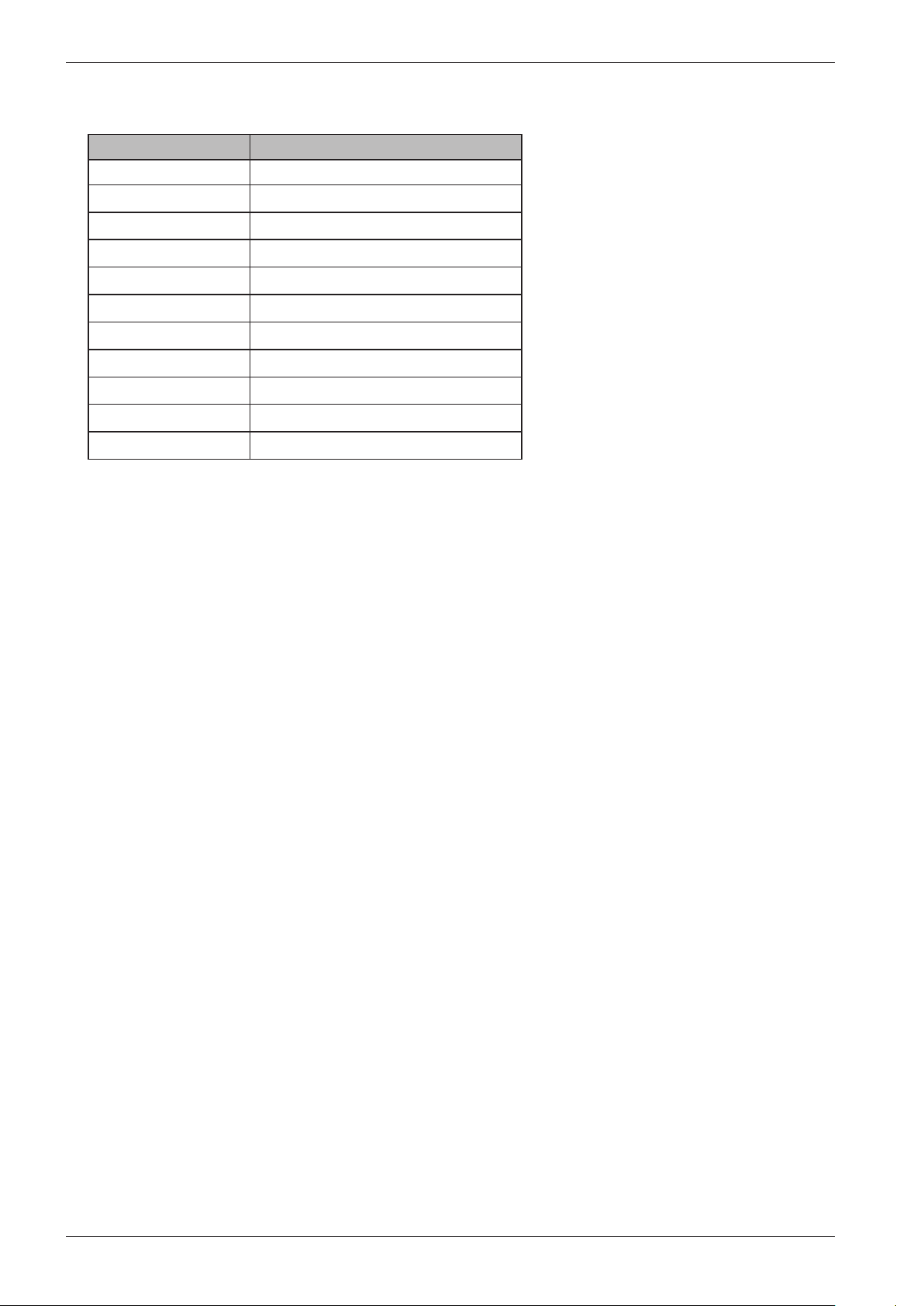
Technical data
Height: 850 mm
Width: 595 mm
Depth: 585 mm
Weight: 73 kg
Cylinder volume: 60 l
Max. load capacity 8 kg/6 kg
Spin speed: 800-1600
Connection: 1-phase 16 A, 3-phase 10 A
Heater output: 2000 W/3000 W
Water pressure/inlet valve: 0.1–1 MPa, 1–10 kp/cm2, 10–100 N/cm2 8 l/min
Wash drum and liquid
compartment:
Stainless steel
Outer panels: Powder-coated and hot-galvanised sheet steel or stainless steel
Installation: Stationary on four adjustable, rubber-clad feet
Water connection: 1.5 m PEX tubing, 3/4"–3/4" or 3/4"–1/2"
Drainage: 1.7 m polypropylene tubing
Protection class: IP X4
Water consumption (tested normal
programme)
59 litres, 3 rinses (5 kg/6 kg
<72 litres, 5 rinses (6 kg)
<69 litres, 5 rinses (5 kg)
Water consumption (tested normal
programme)
1.02 kWh (6 kg)
0.95 kWh (5 kg)
Electricity consumption, Standby:
- Machine turned off
- Delayed start
- Programme ended
<0.3 W
<6.0 W
<3.0 W
Tools
Torx: T25, T20, T10
Ring spanner: 11/16", 16 mm, 13 mm,
10 mm
Socket screwdriver 10 mm
Extended socket 24 mm + ratchet
handle
Allen key 5 mm + small ratchet handle
Plastic hammer
Phillips screwdriver
Wire cutter
Service manual WM70.C
22
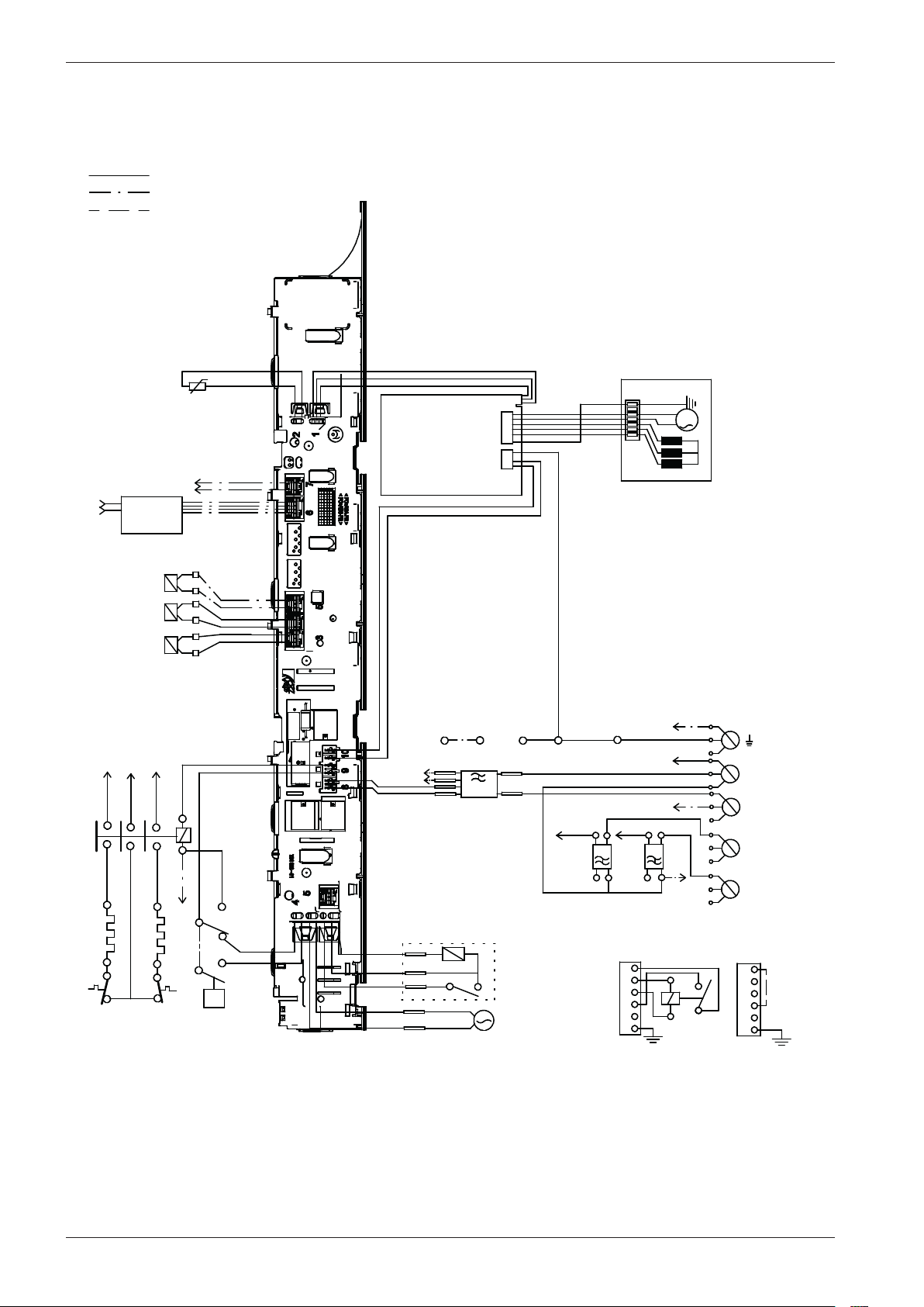
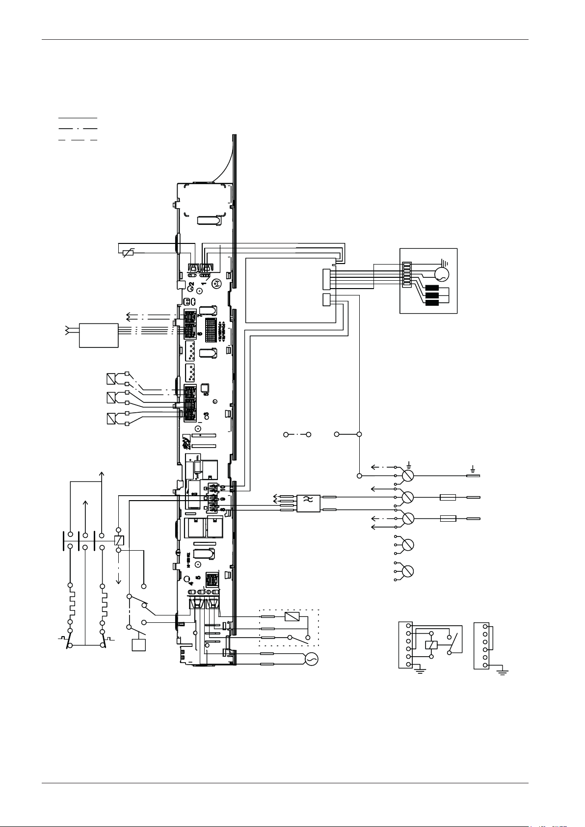
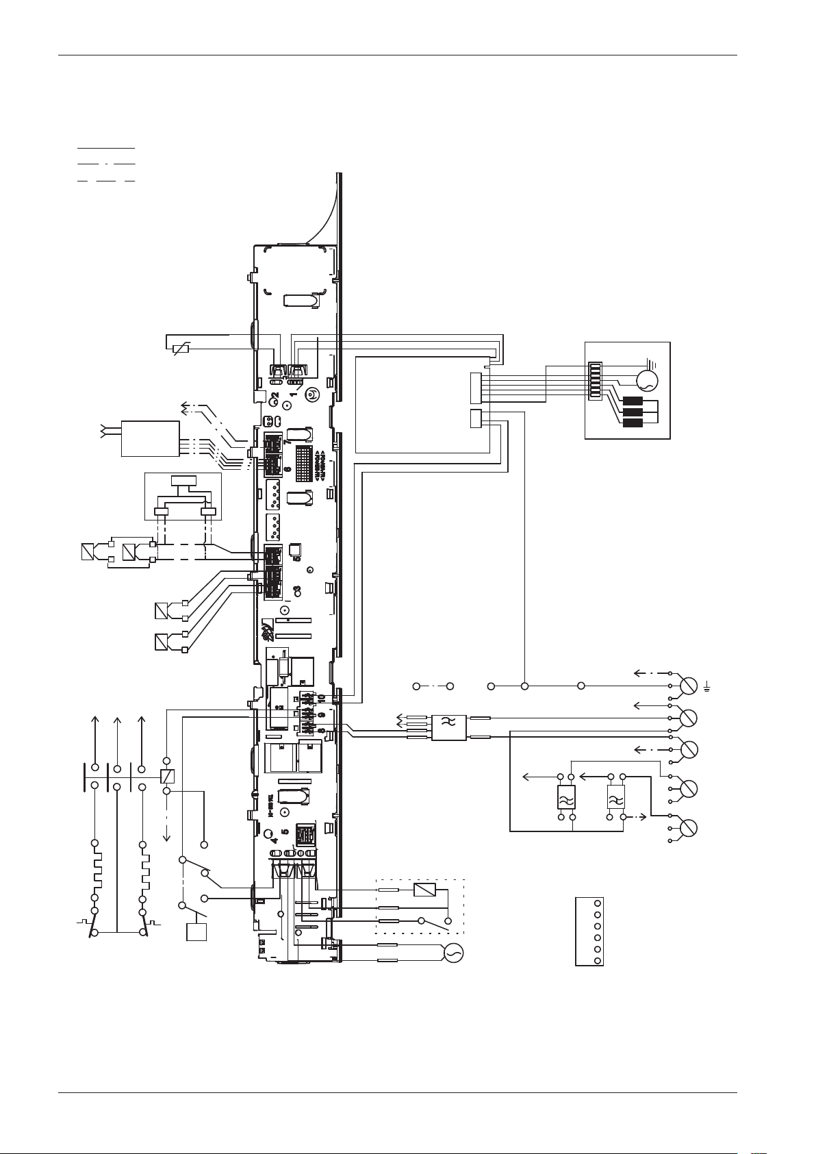
Wiring diagram WM70.C
This document must not be copied without
our written pemission, and the contents
thereof must not be imparted to a third party
nor be used for any unauthorized purpose.
Contravention will be prosecuted.
Asko Appliance AB
CIRCUIT DIAGRAM WM70.C
80 886 19 - 00
WIRES IN ALL MACHINES
INTERNAL CONNECTION
RESISTANCES AT ROOM TEMPERATURE (CA. 20°C/68°F)
VALUES WITHIN +/-10% ARE REGARDED AS NORMAL COMPONENT
F: RADIO INTERFERENCE SUPPRESSION FILTER 680K Ohm
EL: HEATING ELEMENT 25 Ohm
AP: DRAIN PUMP 50 Hz 144 Ohm
AP: DRAIN PUMP 60 Hz 76 Ohm
AV: DRAIN VALVE 110/134 Ohm
LL: DOOR LOCK, 1-2 122 Ohm
NTC: THERMISTOR 6.1 - 3.8 K Ohm
IV 1: INLET VALVE 1 3.7 K Ohm
IV 2: INLET VALVE 2 3.7 K Ohm
IV3: INLET VLAVE 3 3.5 K Ohm
MO: MOTOR, 1-3 4,3±7% Ohm
1-2 4,3±7% Ohm
2-3 4,3±7% Ohm
MCU: MOTOR CONTROL UNIT
N: PRESSURE SWITCH
TS: PRESSURE SENSOR
TG: TACHO GENERATOR
BA: CONTAINER
INKB: INCOMING GROUND
CI: COMMUNICATIONS INTERFACE
IV2
IV1
NTC
F
TS
AP/AV
LL
MO
MCU
3
2
1
CABLE POSITIONS
1: MOTOR COMMUNICATION
2: THERMISTOR
3: INLET VALVES
4: DOOR LOCK, DRAIN PUMP, PREASSURE SWITCH
6:
COMMUNICATION INTERFACE
7: COIN COLLECTOR
8: POWER
9: HEATING ELEMENT, PREASSURE SWITCH
10: MOTOR POWER
3
1
2
TG
S1
S4
S5
<N
N14
N12
N16
N11
EL1
F31
N
R43
R44
R34
R33
R23
R24
RA
RB
EL
INKB
BA
N
L2
L3
L1
R33
R43
EL2
F21
F
B2
F2
F3
B3
R23
IV3
AV BO
WIRES IN SOME MACHINES
CI
WIRING WITH
COINMETER
BLACK
B1
B2BROWN
B5
B4
B3
YELLOW-
GREEN
BLUE
B6
BLACK
BLUE
B2
B1
B6
B5
B4
B3
WIRING WITHOUT
COINMETER
B1
B4
B6
CI
N
L1
R33
B2/F21
B6
F1
F2
F1
F21
F22
F31
F32
F22/32
F2
INKB
F31
1 Phase, 16 A
N
L1
R33
B2
B6
F1
F22/32
F2
INKB
F21
1 Phase, 10 A
3 Phase, 10A
B5
2010-05-20
SERVICE MEN
U
TURN OFF POWER (S1)
WAIT FOR AT LEAST 5 SEC
HOLD S4
TURN ON POWER (S1)
PRESS S4 5 TIMES TO ENTER SERVICE MENU
PRESS DOOR OPENING (S5) TO CHANGE MENU STEP
ROTATE DIAL TO CHANGE IN STEP
PRESSING START/STOP (S4) STORES AND EXITS SERVICE MENU
USER SETTINGS MENU
TURN OFF POWER (S1)
WAIT FOR AT LEAST 5 SEC
HOLD S5
TURN ON POWER (S1)
PRESS S5 5 TIMES TO ENTER MENU
Service manual WM70.C
23
This document must not be copied without
our written pemission, and the contents
thereof must not be imparted to a third party
nor be used for any unauthorized purpose.
Contravention will be prosecuted.
Asko Appliance AB
CIRCUIT DIAGRAM WM70.C
80 886 19 - 00
WIRES IN ALL MACHINES
INTERNAL CONNECTION
RESISTANCES AT ROOM TEMPERATURE (CA. 20°C/68°F)
VALUES WITHIN +/-10% ARE REGARDED AS NORMAL COMPONENT
F: RADIO INTERFERENCE SUPPRESSION FILTER 680K Ohm
EL: HEATING ELEMENT 25 Ohm
AP: DRAIN PUMP 50 Hz 144 Ohm
AP: DRAIN PUMP 60 Hz 76 Ohm
AV: DRAIN VALVE 110/134 Ohm
LL: DOOR LOCK, 1-2 122 Ohm
NTC: THERMISTOR 6.1 - 3.8 K Ohm
IV 1: INLET VALVE 1 3.7 K Ohm
IV 2: INLET VALVE 2 3.7 K Ohm
IV3: INLET VLAVE 3 3.5 K Ohm
MO: MOTOR, 1-3 4,3±7% Ohm
1-2 4,3±7% Ohm
2-3 4,3±7% Ohm
MCU: MOTOR CONTROL UNIT
N: PRESSURE SWITCH
TS: PRESSURE SENSOR
TG: TACHO GENERATOR
BA: CONTAINER
INKB: INCOMING GROUND
CI: COMMUNICATIONS INTERFACE
IV2
IV1
NTC
F
TS
AP/AV
LL
MO
MCU
3
2
1
CABLE POSITIONS
1: MOTOR COMMUNICATION
2: THERMISTOR
3: INLET VALVES
4: DOOR LOCK, DRAIN PUMP, PREASSURE SWITCH
6:
COMMUNICATION INTERFACE
7: COIN COLLECTOR
8: POWER
9: HEATING ELEMENT, PREASSURE SWITCH
10: MOTOR POWER
3
1
2
TG
S1
S4
S5
<N
N14
N12
N16
N11
EL1
F31
N
R43
R44
R34
R33
R23
R24
RA
RB
EL
INKB
BA
N
L2
L3
L1
R33
R43
EL2
F21
F
B2
F2
F3
B3
R23
IV3
AV BO
WIRES IN SOME MACHINES
CI
WIRING WITH
COINMETER
BLACK
B1
B2BROWN
B5
B4
B3
YELLOW-
GREEN
BLUE
B6
BLACK
BLUE
B2
B1
B6
B5
B4
B3
WIRING WITHOUT
COINMETER
B1
B4
B6
CI
N
L1
R33
B2/F21
B6
F1
F2
F1
F21
F22
F31
F32
F22/32
F2
INKB
F31
1 Phase, 16 A
N
L1
R33
B2
B6
F1
F22/32
F2
INKB
F21
1 Phase, 10 A
3 Phase, 10A
B5
2010-05-20
SERVICE MENU
TURN OFF POWER (S1)
WAIT FOR AT LEAST 5 SEC
HOLD S4
TURN ON POWER (S1)
PRESS S4 5 TIMES TO ENTER SERVICE MENU
PRESS DOOR OPENING (S5) TO CHANGE MENU STEP
ROTATE DIAL TO CHANGE IN STEP
PRESSING START/STOP (S4) STORES AND EXITS SERVICE MENU
USER SETTINGS MENU
TURN OFF POWER (S1)
WAIT FOR AT LEAST 5 SEC
HOLD S5
TURN ON POWER (S1)
PRESS S5 5 TIMES TO ENTER MENU
Service manual WM70.C
24
Wiring diagram WM70.C WC US/CA
This document must not be copied without
our written pemission, and the contents
thereof must not be imparted to a third party
nor be used for any unauthorized purpose.
Contravention will be prosecuted.
Asko Appliance AB
CIRCUIT DIAGRAM WM70.C WC US/CA
80 893 65 - 01
WIRES IN ALL MACHINES
INTERNAL CONNECTION
RESISTANCES AT ROOM TEMPERATURE (CA. 20°C/68°F)
VALUES WITHIN +/-10% ARE REGARDED AS NORMAL COMPONENT
F: RADIO INTERFERENCE SUPPRESSION FILTER 680K Ohm
EL: HEATING ELEMENT 25 Ohm
AP: DRAIN PUMP 50 Hz 144 Ohm
AP: DRAIN PUMP 60 Hz 76 Ohm
AV: DRAIN VALVE 110/134 Ohm
LL: DOOR LOCK, 1-2 122 Ohm
NTC: THERMISTOR 6.1 - 3.8 K Ohm
IV 1: INLET VALVE 1 3.7 K Ohm
IV 2: INLET VALVE 2 3.7 K Ohm
IV3: INLET VLAVE 3 3.5 K Ohm
MO: MOTOR, 1-3 4,3±7% Ohm
1-2 4,3±7% Ohm
2-3 4,3±7% Ohm
MCU: MOTOR CONTROL UNIT
N: PRESSURE SWITCH
TS: PRESSURE SENSOR
TG: TACHO GENERATOR
BA: CONTAINER
INKB: INCOMING GROUND
CI: COMMUNICATIONS INTERFACE
CM: COIN METER CABLES
IV2
IV1
NTC
F
TS
AP/AV
LL
MO
MCU
3
2
1
CABLE POSITIONS
1: MOTOR COMMUNICATION
2: THERMISTOR
3: INLET VALVES
4: DOOR LOCK, DRAIN PUMP, PREASSURE SWITCH
6: COMMUNICATION INTERFACE
7: COIN COLLECTOR
8: POWER
9: HEATING ELEMENT, PREASSURE SWITCH
10: MOTOR POWER
3
1
2
TG
<N
N14
N12
N16
N11
EL1
N
R43
R44
R34
R33
R23
R24
RA
RB
EL
INKB
BA
EL2
F
RP
AV BO
WIRES IN SOME MACHINES
F1
F2
1 Phase, 16 A
2011-04-14
SERVICEMENU
TURN OFF POWER (S1)
WAIT FOR AT LEAST 5 SEC
HOLD S4
TURN ON POWER (S1)
PRESS S4 5 TIMES TO ENTER SERVICE MENU
PRESS DOOR OPENING (S5) TO CHANGE MENU STEP
ROTATE DIAL TO CHANGE IN STEP
PRESSING START/STOP (S4) STORES AND EXITS SERVICE MENU
USER SETTINGS MENU
TURN OFF POWER (S1)
WAIT FOR AT LEAST 5 SEC
HOLD S5
TURN ON POWER (S1)
PRESS S5 5 TIMES TO ENTER MENU
COMMON PHASE
S1
S5
S4
R33
N
L1
R43 / R23
L
P1
P2
P3
FUSE
FUSE
Service manual WM70.C
25
This document must not be copied without
our written pemission, and the contents
thereof must not be imparted to a third party
nor be used for any unauthorized purpose.
Contravention will be prosecuted.
Asko Appliance AB
CIRCUIT DIAGRAM WM70.C WC US/CA
80 893 65 - 01
WIRES IN ALL MACHINES
INTERNAL CONNECTION
RESISTANCES AT ROOM TEMPERATURE (CA. 20°C/68°F)
VALUES WITHIN +/-10% ARE REGARDED AS NORMAL COMPONENT
F: RADIO INTERFERENCE SUPPRESSION FILTER 680K Ohm
EL: HEATING ELEMENT 25 Ohm
AP: DRAIN PUMP 50 Hz 144 Ohm
AP: DRAIN PUMP 60 Hz 76 Ohm
AV: DRAIN VALVE 110/134 Ohm
LL: DOOR LOCK, 1-2 122 Ohm
NTC: THERMISTOR 6.1 - 3.8 K Ohm
IV 1: INLET VALVE 1 3.7 K Ohm
IV 2: INLET VALVE 2 3.7 K Ohm
IV3: INLET VLAVE 3 3.5 K Ohm
MO: MOTOR, 1-3 4,3±7% Ohm
1-2 4,3±7% Ohm
2-3 4,3±7% Ohm
MCU: MOTOR CONTROL UNIT
N: PRESSURE SWITCH
TS: PRESSURE SENSOR
TG: TACHO GENERATOR
BA: CONTAINER
INKB: INCOMING GROUND
CI: COMMUNICATIONS INTERFACE
CM: COIN METER CABLES
IV2
IV1
NTC
F
TS
AP/AV
LL
MO
MCU
3
2
1
CABLE POSITIONS
1: MOTOR COMMUNICATION
2: THERMISTOR
3: INLET VALVES
4: DOOR LOCK, DRAIN PUMP, PREASSURE SWITCH
6: COMMUNICATION INTERFACE
7: COIN COLLECTOR
8: POWER
9: HEATING ELEMENT, PREASSURE SWITCH
10: MOTOR POWER
3
1
2
TG
<N
N14
N12
N16
N11
EL1
N
R43
R44
R34
R33
R23
R24
RA
RB
EL
INKB
BA
EL2
F
RP
AV BO
WIRES IN SOME MACHINES
F1
F2
1 Phase, 16 A
2011-04-14
SERVICEMENU
TURN OFF POWER (S1)
WAIT FOR AT LEAST 5 SEC
HOLD S4
TURN ON POWER (S1)
PRESS S4 5 TIMES TO ENTER SERVICE MENU
PRESS DOOR OPENING (S5) TO CHANGE MENU STEP
ROTATE DIAL TO CHANGE IN STEP
PRESSING START/STOP (S4) STORES AND EXITS SERVICE MENU
USER SETTINGS MENU
TURN OFF POWER (S1)
WAIT FOR AT LEAST 5 SEC
HOLD S5
TURN ON POWER (S1)
PRESS S5 5 TIMES TO ENTER MENU
COMMON PHASE
S1
S5
S4
R33
N
L1
R43 / R23
L
P1
P2
P3
FUSE
FUSE
Service manual WM70.C
26
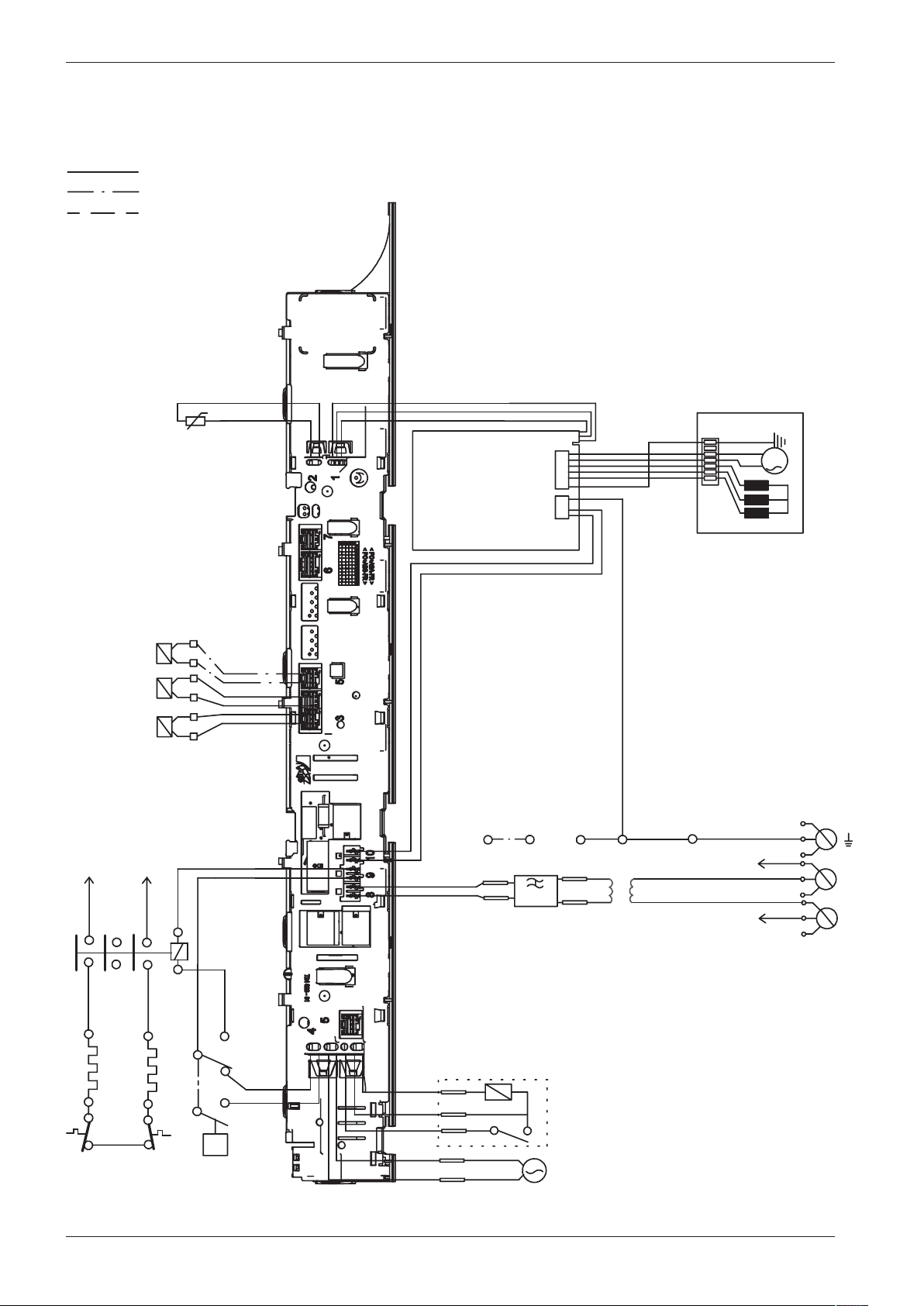
Wiring diagram WM70.C US/CA
This document must not be copied without
our written pemission, and the contents
thereof must not be imparted to a third party
nor be used for any unauthorized purpose.
Contravention will be prosecuted.
Asko Appliance AB
CIRCUIT DIAGRAM WM70.C US/CA
80 896 25 - 00
WIRES IN ALL MACHINES
INTERNAL CONNECTION
IV2
IV1
NTC
F
TS
AP/AV
LL
MO
MCU
3
2
1
CABLE POSITIONS
1: MOTOR COMMUNICATION
2: THERMISTOR
3: INLET VALVES
4: DOOR LOCK, DRAIN PUMP, PREASSURE SWITCH
6:
COMMUNICATION INTERFACE
7: COIN COLLECTOR
8: POWER
9: HEATING ELEMENT, PREASSURE SWITCH
10: MOTOR POWER
3
1
2
TG
S1
S4
S5
<N
N14
N12
N16
N11
EL1
N
R43
R44
R34
R33
R23
R24
RA
RB
EL
INKB
BA
N
L2
L3
L1
R33
EL2
L1
F
B2
IV3
AV BO
WIRES IN SOME MACHINES
CI
WIRING WITH
COINMETER
BLACK
B1
B2BROWN
B5
B4
B3
YELLOW-
GREEN
BLUE
B6
BLACK
BLUE
B2
B1
B6
B5
B4
B3
WIRING WITHOUT
COINMETER
B1
B4
B6
CI
F1
F2
1 Phase, 16 A
B5
2010-05-20
SERVIC
E MENU
TURN OFF POWER (S1)
WAIT FOR AT LEAST 5 SEC
HOLD S4
TURN ON POWER (S1)
PRESS S4 5 TIMES TO ENTER SERVICE MENU
PRESS DOOR OPENING (S5) TO CHANGE MENU STEP
ROTATE DIAL TO CHANGE IN STEP
PRESSING START/STOP (S4) STORES AND EXITS SERVICE MENU
USER SETTINGS MENU
TURN OFF POWER (S1)
WAIT FOR AT LEAST 5 SEC
HOLD S5
TURN ON POWER (S1)
PRESS S5 5 TIMES TO ENTER MENU
R23
N
L
Fuse
Fuse
RESISTANCES AT ROOM TEMPERATURE (CA. 20°C/68°F)
VALUES WITHIN +/-10% ARE REGARDED AS NORMAL COMPONENT
F: RADIO INTERFERENCE SUPPRESSION FILTER 680K Ohm
EL1: HEATING ELEMENT 25 Ohm
EL2: HEATING ELEMENT 52 Ohm
AP: DRAIN PUMP 60 Hz 76 Ohm
AV: DRAIN VALVE 110 Ohm
LL: DOOR LOCK, 1-2 122 Ohm
NTC: THERMISTOR 6.1 - 3.8 K Ohm
IV 1: INLET VALVE 1 3.7 K Ohm
IV 2: INLET VALVE 2 3.7 K Ohm
IV3: INLET VALVE 3 3.5 K Ohm
MO: MOTOR, 1-3 4,3±7% Ohm
1-2 4,3±7% Ohm
2-3 4,3±7% Ohm
MCU: MOTOR CONTROL UNIT
N: PRESSURE SWITCH
TS: PRESSURE SENSOR
TG: TACHO GENERATOR
BA: CONTAINER
INKB: INCOMING GROUND
CI: COMMUNICATIONS INTERFACE
Service manual WM70.C
27
This document must not be copied without
our written pemission, and the contents
thereof must not be imparted to a third party
nor be used for any unauthorized purpose.
Contravention will be prosecuted.
Asko Appliance AB
CIRCUIT DIAGRAM WM70.C US/CA
80 896 25 - 00
WIRES IN ALL MACHINES
INTERNAL CONNECTION
IV2
IV1
NTC
F
TS
AP/AV
LL
MO
MCU
3
2
1
CABLE POSITIONS
1: MOTOR COMMUNICATION
2: THERMISTOR
3: INLET VALVES
4: DOOR LOCK, DRAIN PUMP, PREASSURE SWITCH
6:
COMMUNICATION
INTERFACE
7: COIN COLLECTOR
8: POWER
9: HEATING ELEMENT, PREASSURE SWITCH
10: MOTOR POWER
3
1
2
TG
S1
S4
S5
<N
N14
N12
N16
N11
EL1
N
R43
R44
R34
R33
R23
R24
RA
RB
EL
INKB
BA
N
L2
L3
L1
R33
EL2
L1
F
B2
IV3
AV BO
WIRES IN SOME MACHINES
CI
WIRING WITH
COINMETER
BLACK
B1
B2BROWN
B5
B4
B3
YELLOW-
GREEN
BLUE
B6
BLACK
BLUE
B2
B1
B6
B5
B4
B3
WIRING WITHOUT
COINMETER
B1
B4
B6
CI
F1
F2
1 Phase, 16 A
B5
2010-05-20
SERVICE MENU
TURN OFF POWER (S1)
WAIT FOR AT LEAST 5 SEC
HOLD S4
TURN ON POWER (S1)
PRESS S4 5 TIMES TO ENTER SERVICE MENU
PRESS DOOR OPENING (S5) TO CHANGE MENU STEP
ROTATE DIAL TO CHANGE IN STEP
PRESSING START/STOP (S4) STORES AND EXITS SERVICE MENU
USER SETTINGS MENU
TURN OFF POWER (S1)
WAIT FOR AT LEAST 5 SEC
HOLD S5
TURN ON POWER (S1)
PRESS S5 5 TIMES TO ENTER MENU
R23
N
L
Fuse
Fuse
RESISTANCES AT ROOM TEMPERATURE (CA. 20°C/68°F)
VALUES WITHIN +/-10% ARE REGARDED AS NORMAL COMPONENT
F: RADIO INTERFERENCE SUPPRESSION FILTER 680K Ohm
EL1: HEATING ELEMENT 25 Ohm
EL2: HEATING ELEMENT 52 Ohm
AP: DRAIN PUMP 60 Hz 76 Ohm
AV: DRAIN VALVE 110 Ohm
LL: DOOR LOCK, 1-2 122 Ohm
NTC: THERMISTOR 6.1 - 3.8 K Ohm
IV 1: INLET VALVE 1 3.7 K Ohm
IV 2: INLET VALVE 2 3.7 K Ohm
IV3: INLET VALVE 3 3.5 K Ohm
MO: MOTOR, 1-3 4,3±7% Ohm
1-2 4,3±7% Ohm
2-3 4,3±7% Ohm
MCU: MOTOR CONTROL UNIT
N: PRESSURE SWITCH
TS: PRESSURE SENSOR
TG: TACHO GENERATOR
BA: CONTAINER
INKB: INCOMING GROUND
CI: COMMUNICATIONS INTERFACE
Service manual WM70.C
28
Wiring diagram WM70.C 440V
WIRES IN ALL MACHINES
INTERNAL CONNECTION
IV2
IV1
NTC
TS
AP/AV
LL
MO
MCU
3
2
1
CABLE POSITIONS
1: MOTOR COMMUNICATION
2: THERMISTOR
3: INLET VALVES
4: DOOR LOCK, DRAIN PUMP, PREASSURE SWITCH
6:
COMMUNICATION
INTERFACE
7: COIN COLLECTOR
8: POWER
9: HEATING ELEMENT, PREASSURE SWITCH
10: MOTOR POWER
3
1
2
TG
<N
N14
N12
N16
N11
EL1
L1
R43
R44
R34
R33
R23
R24
RA
RB
EL
INKB
BA
L2R23
EL2
L2
IV3
AV BO
WIRES IN SOME MACHINES
R43
L1
F
F1
F2
T
Blue
Orange
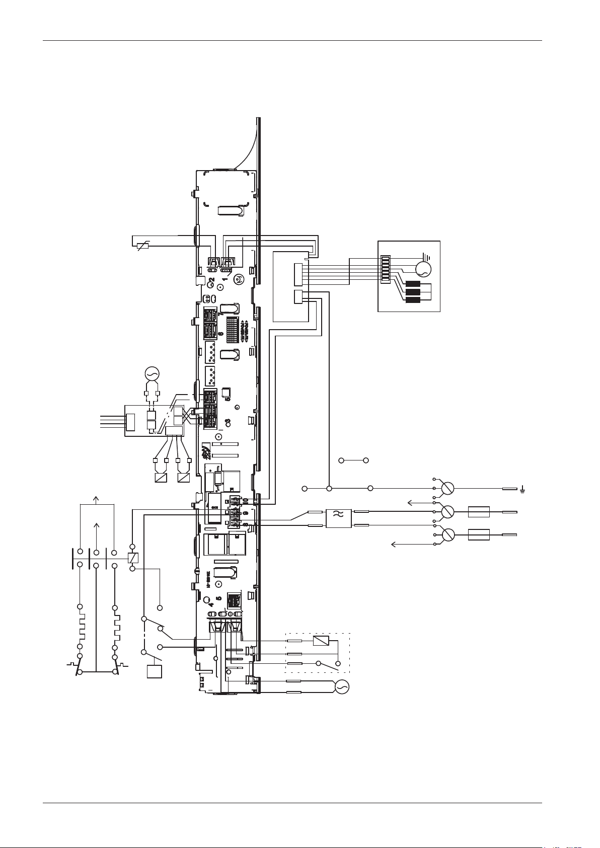
Service manual WM70.C
29
This document must not be copied without
our written pemission, and the contents
thereof must not be imparted to a third party
nor be used for any unauthorized purpose.
Contravention will be prosecuted.
Asko Appliance AB
CIRCUIT DIAGRAM WM70.C MARINE
80 896 27 - 01
RESISTANCES AT ROOM TEMPERATURE (CA. 20°C/68°F)
VALUES WITHIN +/-10% ARE REGARDED AS NORMAL COMPONENT
F: RADIO INTERFERENCE SUPPRESSION FILTER 680K Ohm
EL1: HEATING ELEMENT 25 Ohm
EL2: HEATING ELEMENT 52 Ohm
AP: DRAIN PUMP 60 Hz 76 Ohm
AV: DRAIN VALVE 110/134 Ohm
LL: DOOR LOCK, 1-2 122 Ohm
NTC: THERMISTOR 6.1 - 3.8 K Ohm
IV 1: INLET VALVE 1 3.7 K Ohm
IV 2: INLET VALVE 2 3.7 K Ohm
IV3: INLET VLAVE 3 3.5 K Ohm
MO: MOTOR, 1-3 4,3±7% Ohm
1-2 4,3±7% Ohm
2-3 4,3±7% Ohm
MCU: MOTOR CONTROL UNIT
N: PRESSURE SWITCH
TS: PRESSURE SENSOR
TG: TACHO GENERATOR
BA: CONTAINER
INKB: INCOMING GROUND
T: TRANSFORMER
S1
S4
S5
2012-09-10
SERVICE MENU
TURN OFF POWER (S1)
WAIT FOR AT LEAST 5 SEC
HOLD S4
TURN ON POWER (S1)
PRESS S4 5 TIMES TO ENTER SERVICE MENU
PRESS DOOR OPENING (S5) TO CHANGE MENU STEP
ROTATE DIAL TO CHANGE IN STEP
PRESSING START/STOP (S4) STORES AND EXITS SERVICE MENU
USE
R
SETTINGS
M
ENU
TURN OFF POWER (S1)
WAIT FOR AT LEAST 5 SEC
HOLD S5
TURN ON POWER (S1)
PRESS S5 5 TIMES TO ENTER MENU
Service manual WM70.C
30
This document must not be copied without
our written pemission, and the contents
thereof must not be imparted to a third party
nor be used for any unauthorized purpose.
Contravention will be prosecuted.
Asko Appliance AB
CIRCUIT DIAGRAM WM70.C HWC
80 931 37 - 00
WIRES IN ALL MACHINES
INTERNAL CONNECTION
RESISTANCES AT ROOM TEMPERATURE (CA. 20°C/68°F)
VALUES WITHIN +/-10% ARE REGARDED AS NORMAL COMPONENT
F: RADIO INTERFERENCE SUPPRESSION FILTER 680K Ohm
EL: HEATING ELEMENT 25 Ohm
AP: DRAIN PUMP 50 Hz 144 Ohm
AP: DRAIN PUMP 60 Hz 76 Ohm
AV: DRAIN VALVE 110/134 Ohm
LL: DOOR LOCK, 1-2 122 Ohm
NTC: THERMISTOR 6.1 - 3.8 K Ohm
IV 1: INLET VALVE 1 3.7 K Ohm
IV 2: INLET VALVE 2 3.7 K Ohm
IV3: INLET VLAVE 3 3.5 K Ohm
MO: MOTOR, 1-3 4,3±7% Ohm
1-2 4,3±7% Ohm
2-3 4,3±7% Ohm
MCU: MOTOR CONTROL UNIT
N: PRESSURE SWITCH
TS: PRESSURE SENSOR
TG: TACHO GENERATOR
BA: CONTAINER
INKB: INCOMING GROUND
CI: COMMUNICATIONS INTERFACE
MV: MAGNETIC VALVE
SV: SWITCHING VALVE
IV2
IV1
NTC
F
TS
AP/AV
LL
MO
MCU
3
2
1
CABLE POSITIONS
1: MOTOR COMMUNICATION
2: THERMISTOR
3: INLET VALVES
4: DOOR LOCK, DRAIN PUMP, PREASSURE SWITCH
6:
COMMUNICATION INTERFACE
7: COIN COLLECTOR
8: POWER
9: HEATING ELEMENT, PREASSURE SWITCH
10: MOTOR POWER
3
1
2
TG
S1
S4
S5
<N
N14
N12
N16
N11
EL1
F31
N
R43
R44
R34
R33
R23
R24
RA
RB
EL
INKB
BA
N
L2
L3
L1
R33
R43
EL2
F21
F
CM2
F2
F3
CM3
R23
AV BO
WIRES IN SOME MACHINES
CI
PHASE
BLACK
CM1
CM2
BROWN
CM5
CM4
CM3
GROUND
BLUE
CM6
BLACK
BLUE
CM1
CM4
CM6
CI
F1
F2
F21
F22
F31
F32
N
L1
R33
CM2
CM6
F1
F22/32
F2
INKB
F21
1 Phase, 10 A
3 Phase, 10A
CM5
2011-11-11
SERVICE MENU
TURN OFF POWER (S1)
WAIT FOR AT LEAST 5 SEC
HOLD S4
TURN ON POWER (S1)
PRESS S4 5 TIMES TO ENTER SERVICE MENU
PRESS DOOR OPENING (S5) TO CHANGE MENU STEP
ROTATE DIAL TO CHANGE IN STEP
PRESSING START/STOP (S4) STORES AND EXITS SERVICE MENU
USER SETTINGS MENU
TURN OFF POWER (S1)
WAIT FOR AT LEAST 5 SEC
HOLD S5
TURN ON POWER (S1)
PRESS S5 5 TIMES TO ENTER MENU
YELLOW-
GREEN
FROM CONTROL UNIT
NEUTRAL
HEATER
FROM CONTROL UNIT
If coin meter is selected
CM1 and CM4 needs to
be closed to start the
machine (default closed)
CONNECTOR FOR COIN METER
N
L1
R33
CM2/F21
CM6
F1
F22/32
F2
INKB
F31
1 Phase, 16 A
MV
SV
Relay board
Wiring diagram WM70.C HWC
Service manual WM70.C
31
This document must not be copied without
our written pemission, and the contents
thereof must not be imparted to a third party
nor be used for any unauthorized purpose.
Contravention will be prosecuted.
Asko Appliance AB
CIRCUIT DIAGRAM WM70.C HWC
80 931 37 - 00
WIRES IN ALL MACHINES
INTERNAL CONNECTION
RESISTANCES AT ROOM TEMPERATURE (CA. 20°C/68°F)
VALUES WITHIN +/-10% ARE REGARDED AS NORMAL COMPONENT
F: RADIO INTERFERENCE SUPPRESSION FILTER 680K Ohm
EL: HEATING ELEMENT 25 Ohm
AP: DRAIN PUMP 50 Hz 144 Ohm
AP: DRAIN PUMP 60 Hz 76 Ohm
AV: DRAIN VALVE 110/134 Ohm
LL: DOOR LOCK, 1-2 122 Ohm
NTC: THERMISTOR 6.1 - 3.8 K Ohm
IV 1: INLET VALVE 1 3.7 K Ohm
IV 2: INLET VALVE 2 3.7 K Ohm
IV3: INLET VLAVE 3 3.5 K Ohm
MO: MOTOR, 1-3 4,3±7% Ohm
1-2 4,3±7% Ohm
2-3 4,3±7% Ohm
MCU: MOTOR CONTROL UNIT
N: PRESSURE SWITCH
TS: PRESSURE SENSOR
TG: TACHO GENERATOR
BA: CONTAINER
INKB: INCOMING GROUND
CI: COMMUNICATIONS INTERFACE
MV: MAGNETIC VALVE
SV: SWITCHING VALVE
IV2
IV1
NTC
F
TS
AP/AV
LL
MO
MCU
3
2
1
CABLE POSITIONS
1: MOTOR COMMUNICATION
2: THERMISTOR
3: INLET VALVES
4: DOOR LOCK, DRAIN PUMP, PREASSURE SWITCH
6:
COMMUNICATION INTERFACE
7: COIN COLLECTOR
8: POWER
9: HEATING ELEMENT, PREASSURE SWITCH
10: MOTOR POWER
3
1
2
TG
S1
S4
S5
<N
N14
N12
N16
N11
EL1
F31
N
R43
R44
R34
R33
R23
R24
RA
RB
EL
INKB
BA
N
L2
L3
L1
R33
R43
EL2
F21
F
CM2
F2
F3
CM3
R23
AV BO
WIRES IN SOME MACHINES
CI
PHASE
BLACK
CM1
CM2
BROWN
CM5
CM4
CM3
GROUND
BLUE
CM6
BLACK
BLUE
CM1
CM4
CM6
CI
F1
F2
F21
F22
F31
F32
N
L1
R33
CM2
CM6
F1
F22/32
F2
INKB
F21
1 Phase, 10 A
3 Phase, 10A
CM5
2011-11-11
SERVICE MENU
TURN OFF POWER (S1)
WAIT FOR AT LEAST 5 SEC
HOLD S4
TURN ON POWER (S1)
PRESS S4 5 TIMES TO ENTER SERVICE MENU
PRESS DOOR OPENING (S5) TO CHANGE MENU STEP
ROTATE DIAL TO CHANGE IN STEP
PRESSING START/STOP (S4) STORES AND EXITS SERVICE MENU
USER SETTINGS MENU
TURN OFF POWER (S1)
WAIT FOR AT LEAST 5 SEC
HOLD S5
TURN ON POWER (S1)
PRESS S5 5 TIMES TO ENTER MENU
YELLOW-
GREEN
FROM CONTROL UNIT
NEUTRAL
HEATER
FROM CONTROL UNIT
If coin meter is selected
CM1 and CM4 needs to
be closed to start the
machine (default closed)
CONNECTOR FOR COIN METER
N
L1
R33
CM2/F21
CM6
F1
F22/32
F2
INKB
F31
1 Phase, 16 A
MV
SV
Relay board
Service manual WM70.C
32
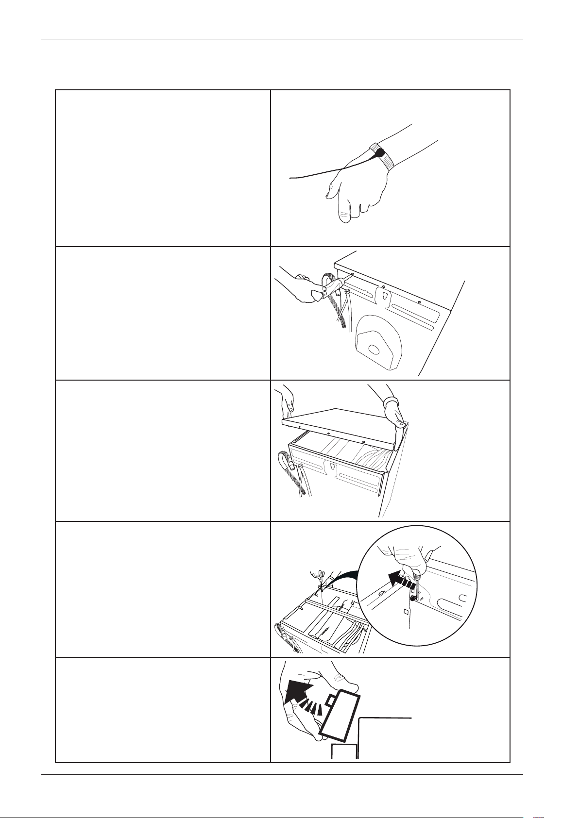
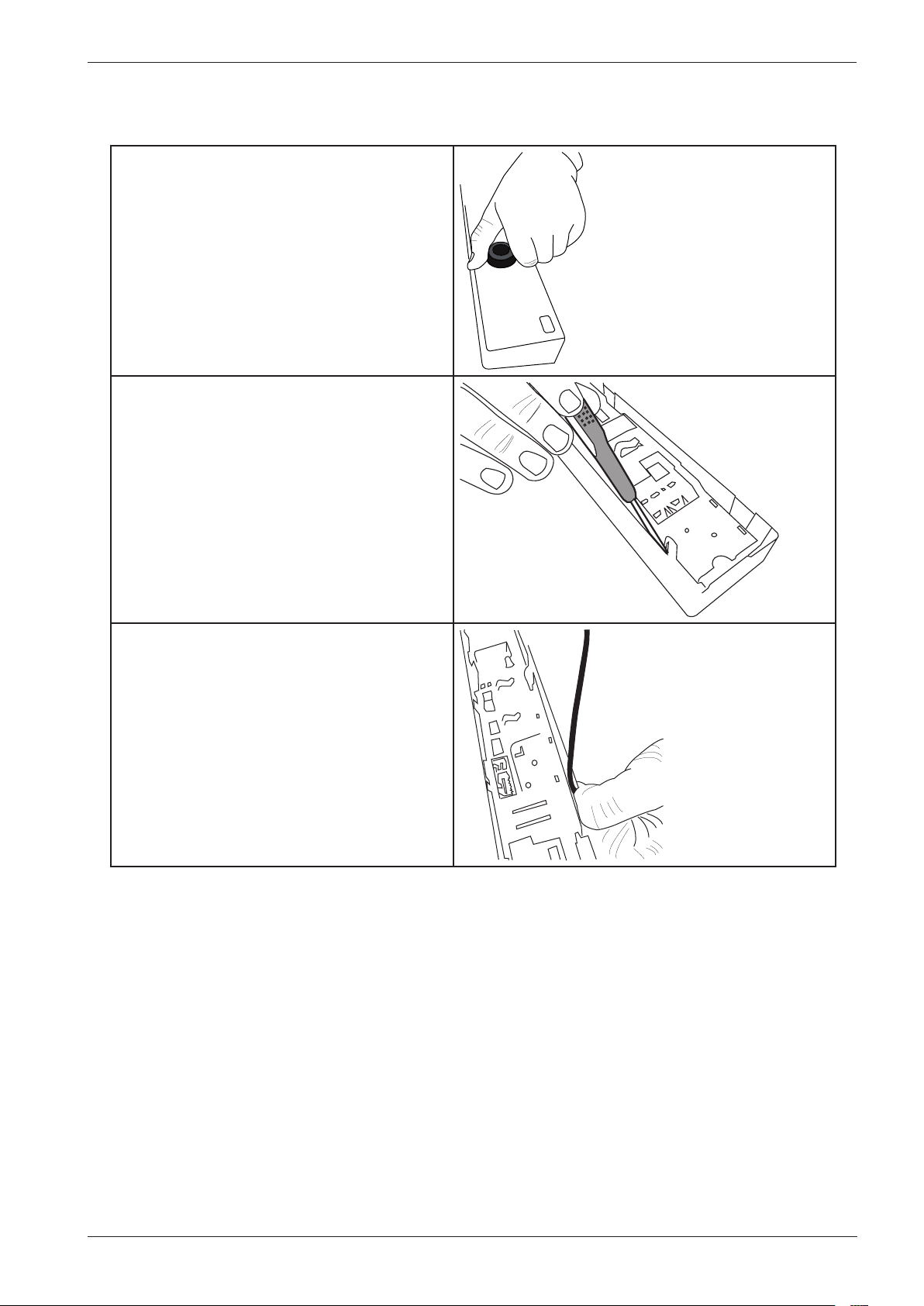
Panel and control card replacement
1. Attach the anti-static wristband to a part
of the machine that is earthed!
NB: An anti-static wristband must be used,
otherwise you risk destroying the control
card.
2. Undo the three screws holding the top
cover in place.
3. Remove the top cover.
4. Use a screwdriver to carefully free the
panel. As you do so, carefully angle the panel
outwards.
5. Remove the panel and the cables. NB:
Don't forget to remove the pressure sensor
tube.
Service manual WM70.C
33
Panel and control card replacement (cont.)
6. Carefully pull the programme selector
from the panel.
7. Use a screwdriver to free the control card
from the panel. NB: The control card must
be placed in an ESD-safe bag.
8. Check that the push button, lens and
decorative inlay are in place. Now carefully
press the new control card into place. NB:
Don't forget to replace the rubber seal.
Service manual WM70.C
34
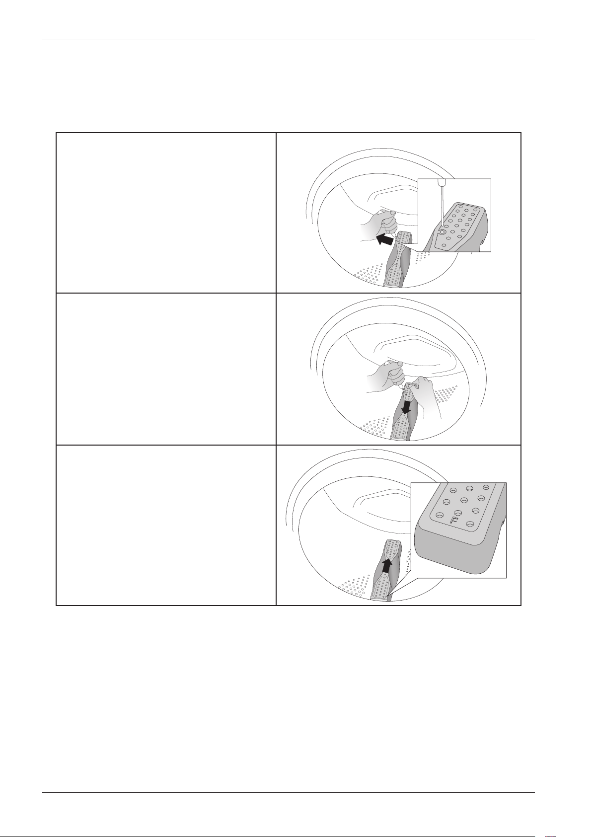
Wash agitator removal
When replacing or cleaning the wash agitators, or when removing items that have fallen through
the wash drum, first you need to remove the agitators. Follow the instructions below.
1. Insert a screwdriver or the like into
the hole on the agitator as illustrated and
carefully pry to the left.
2. Use your other hand to grasp the agitator
and pull it towards you.
3. Lift the agitator.
4. Remove any foreign objects.
5. Place the agitator in the mounting hole
with the letter F towards you. Ensure that
all the agitator fasteners are in their holes
in the drum. Push it away from you until it
fastens.

Service manual WM70.C
35

Service manual WM70.C
36

Service manual WM70.C
37

80 901 14 Service Manual WM70.C ASKO Rev. 05 2012-10-01