Loading ...
Loading ...
Loading ...
The Electronic Thermostat
IMPORTANT: The Energy Smarts Module (ESM) must
be removed before attempting to access the thermostat.
NOTE: for the Electronic Thermostat (ET) changes to re-
main in effect the Energy Smart s Module (ESM) must no._[t
be reconnected, also read the "Water Temperature Regu-
lation" under the "Operating Your Water Heater" section. If
the instructions are not clear, contact a qualified person.
The Energy Smart s Module (ESM) is intended to serve
as the primary interface for operating the water heater;
however, the Electronic Thermostat (ET) may control the
water heater inthe absence of the Energy Smarts Module
(ESM).
The Electronic Thermostat consists of an electronics box
that contains alow voltage power supply, the thermostat
set point knob, relays to switch between the upper and
lower heating elements, one control thermistor, a connec-
tor for the lower element control thermistor, microelectron-
ics to convert the thermistor signals and perform switch-
ing and other logic functions, and a connector to tie the
Electronic Thermostat (ET) to the Energy Smarts Module
(ESM) located on the front of the water heater jacket. The
majority of the self-diagnostics are located in the Electronic
Thermostat (ET), including the dry-fire protection intelli-
gence. The thermostat circuit is designed so that when the
upper heating element calls for heat, the power is directed
to that element even if the lower element is also calling for
heat.
Diagnostic LED Light
The Green/Red LED light indicates the status of the elec-
tronic thermostat (See Figure 10A).
• Green LED will signal normal operation. The green
LED will blink 2 times per second to indicate that power is
applied to the upper heating element and at a faster rate
(4 times per second) to indicate that the lower heating ele-
ment is powered.
• Red LED will flash error codes. If a fault is detected by
the electronic thermostat, the LED light indicator will use
the red LED to indicate the fault detected. The flash code
sequence is to consist of 1/2 second flashes of the red
LED each separated by a 1/2 second off period.
The number of flashes indicates the fault code number.
(See diagnostic code chart section in this manual).
After the last 1/2 second "on" period, the LED will remain
off until a total of 5 seconds has elapsed for the fault in-
dication cycle (there is a 5 seconds delay before the fault
flash pattern repeats). After the 5 seconds are completed,
the fault indication cycle is repeated starting with the first
1/2 second-flash. The flash sequence will be repeated as
long as the fault remains. Only one fault can be declared
at a time. NOTE: the green LED is turned offwhen a fault
code is being displayed, even though the heater may be
operating in limp mode with an element on. See diagnos-
tic code chart section in this manual.
Overriding The Energy Smart ®
Module (ESM)
If the Energy Smart s Module (ESM) is not working, simply
unplug the interface module and turn the set point knob
on the Electronic Thermostat (ET) to the desired tempera-
ture (See Figures 10A & 10B). To replace a broken or
damaged ESM module, see page 22 for ordering informa-
tion.
12
Electrical Shock Hazard
Do not remove the plactic
guard from over wiring.
Do not touch electrical wiring.
Failure to do so can result in
death or electrical shock.
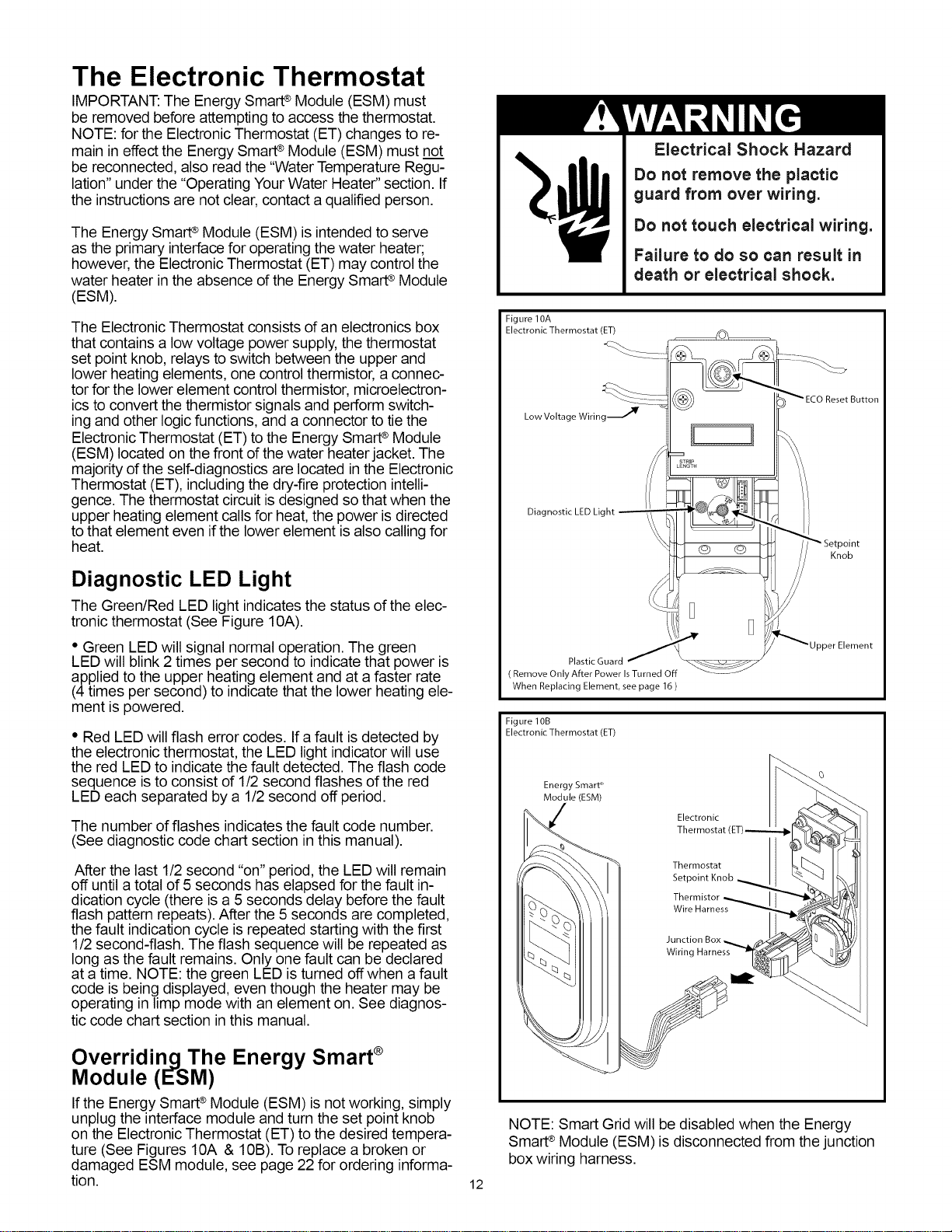
Figure 10A
Electronic Thermostat (ET)
Low Voltage Wiring --.--,''_
Diagnostic LED Light
@ ©
Knob
Plastic Guard
( Remove Only After Power IsTurned Off
When Replacing Element, see page 16 )
Figure 10B
Electronic Thermostat (ET)
Energy SmaW
Module (ESM)
Electronic
Thermostat,
Thermostat
Thermistor
Wire Harness
Junction
Wiring Harness
NOTE: Smart Grid will be disabled when the Energy
SmarP Module (ESM) is disconnected from the junction
box wiring harness.
Loading ...
Loading ...
Loading ...