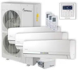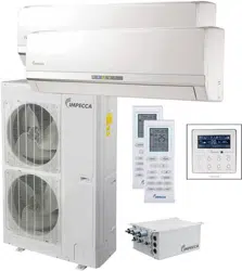
Flex+ Series R410A
Systems
―Outdoor Unit
Owner's Manual Impecca Air
Conditioners
ISMO-6021
Thank you for choosing Impecca air conditioners, please read this owner’s manual carefully
before operation and keep it for future reference.
Impecca reserves the right to interpret this manual which will be subject to any change due
to product improvement without further notice.
v. 1.1

Preface
Flex + Series adopt the advanced manufacturing technology and takes the environmental-
friendly R410A as refrigerant, which is a green product in the 21st century. Please carefully read
the manual before installation and operation.
1) Flex + Series systems conform to design standard ARI 210240-2008.
2) To ensure safety when operating this system, please strictly follow the instructions in this
manual.
3) Make sure that the manual is kept by the operators or serviceman.
4) The refrigerant pipes and accessories must be designed exclusively for R410A.
5) The total capacity of the indoor units which runs at the same time cannot exceed the capacity of
the outdoor units; otherwise, the cooling (heating) effect of each indoor unit would be lower
than the nominal capacity.
6) In case of malfunction, please examine the following items and contact our appointed service
centers as soon as possible.
Nameplate (model, cooling capacity, product code, ex-factory date).
Malfunction status (detail description of conditions before and after malfunction occurs).
7) It is a normal phenomenon that the fan of indoor unit will still run for 20~70 seconds after the
indoor unit receives the “stop” signal so as to make full use of the waste heat.
8) When the work mode of the indoors is conflict with the modes of outdoor units, it will be
indicated on the display of the wired controller in five seconds and then the indoor unit will
stop. In this case, please harmonize their work modes: the cooling mode is compatible with the
dry mode.
9) If the supply power fails when the unit is running, then the indoor unit will send the “start”
signal to the outdoor unit three minutes later after the power recovery.
10) The power cable and transmission line must not be twisted together, but instead of separated
with an interval of at least 2cm; otherwise it may be result in communication problem.
11) This appliance is not intended for use by persons (including children) with reduced physical,
sensory or mental capabilities, or lack of experience and knowledge, unless they have been
given supervision or instruction concerning use of the appliance by a person responsible for
their safety. Children should be supervised to ensure that they do not play with the appliance.
12) All graphics and information in this manual are only for reference. Manufacturer reserves the
right for changes in terms of sales or production at any time and without prior notice.
This product must not be disposed together with the domestic waste. This product has
to be disposed at an appointed place for recycling of electrical and electronic appliances.
Thank you for purchasing Impecca air conditioners. Before using, please read
this manual carefully and keep it properly for further reference.


I
Contents
1 Safety Precautions ..................................................................................................................... 1
2 Attention for Installation ........................................................................................................... 3
2.1 Precautions for R410A .................................................................................................. 3
2.2 Precaution for Installation ............................................................................................. 3
2.3 Precaution for Operation Test........................................................................................ 3
2.4 Accessories .................................................................................................................... 3
3 Product Introduction ................................................................................................................. 4
3.1 Names of Main Parts ..................................................................................................... 4
3.2 Combinations for Outdoor and Indoor Units ................................................................ 4
3.3 Parts and Components of Unit ...................................................................................... 5
3.4 Working Temperature Range ......................................................................................... 5
4 Selection of Installation Location and Precautions ................................................................... 6
4.1 Selection of Installation Location ................................................................................. 6
4.2 Outline Dimension of Outdoor Unit .............................................................................. 7
4.3 Installation and Servicing Space ................................................................................... 7
5 Installation Instruction .............................................................................................................. 8
6 Installation of Refrigerant Pipes ............................................................................................... 9
6.1 Allowable Length and Drop Height of Connecting Pipe .............................................. 9
6.2 Dimension of Connecting Pipe ................................................................................... 10
6.3 Connection of Branch Pipe ......................................................................................... 10
6.4 Connection of Refrigerant Pipes ................................................................................. 11
6.5 Connec
tion of Refrigerant Pipe ................................................................................... 12
6.6 Leak Test ..................................................................................................................... 13
6.7 Vacuum Operation ....................................................................................................... 13
6.8 Refrigerant Charging ................................................................................................... 14
7 Electrical Wiring Work ........................................................................................................... 17
7.1 Wiring Connection ...................................................................................................... 17
7.2 Requirements of Power Circuit and Cable .................................................................. 17
7.3 Ground Requirements ................................................................................................. 18
7.4 Precautions on the Electrical Wiring Work ................................................................. 18
7.5 Precaution of Laying Wires ......................................................................................... 19
7.6 Procedures for Electrical Wiring Work ....................................................................... 19
8 Design of Drainage Pipeline ................................................................................................... 20
8.1 Installation of Drain Hose ........................................................................................... 20
8.2 Design of Drainage Pipeline ....................................................................................... 20
9 Installation of Protective Layer ............................................................................................... 21
10 Test Operation ......................................................................................................................... 22
10.1 Check after Installation ............................................................................................... 22
10.2 Test Operation ............................................................................................................. 22
11 Testing Board Introduction ..................................................................................................... 23
11 . 1 Compose of the Testing Board .................................................................................... 23
11.2 Instruction of Function and Data Section .................................................................... 23

II
12 Troubleshooting ...................................................................................................................... 24
12.1 Check before Contacting Service Center .................................................................... 24
12.2 Problem Handling ....................................................................................................... 25
12.3 Error Description ......................................................................................................... 25
13 Maintenance ............................................................................................................................ 28
13.1 Outdoor Condenser ..................................................................................................... 28
13.2 Drain Pipe ................................................................................................................... 28
13.3 Check before the Seasonal Use ................................................................................... 28
13.4 Maintenance after Seasonal Use ................................................................................. 28
14 After-sales Service .................................................................................................................. 28

Flex + Series
1
1 Safety Precautions
This is t
he safety alert symbol. It is used to alert you to potential personal injury
hazards. Obey all safety messages that follow this symbol to avoid possible injury or
death.
WARNING
This mark indicates procedures which, if improperly performed, might lead to the
death or serious injury of the user.
CAUTION
This mark indicates procedures which, if improperly performed, might possibly result
in personal harm to the user, or damage to property.
NOTICE
NOTICE is used to address practices not related to personal injury.
WAR N I N G
1) Instructions for installation and use of this product are provided by the manufacturer.
2) Installation must be performed in accordance with the requirements of NEC and CEC by appointed
personnel only.
3) The installation should be left to the appointed service center and according to the instructions given in the
manual. Improper installation may cause fall down, water leakage, electric shock or fire etc.
4) For operating the air conditioner pleasantly, please install it as outlined in this installation manual.
5) The power supply must adopt the special circuit with air switch protection and assure it has enough capacity
6) Connect the indoor unit, BU module and outdoor unit with the room air conditioner piping and cord
available from our standard parts. This installation manual describes the correct connections using the
installation set available from our standard parts.
7) Before installation, check the parameter of power cord and make sure that it complies with the power
supply requirement on the nameplate. Make sure the power supply is safe.
8) This air conditioner must be properly grounded through the receptacle to avoid electric shock. The ground
wire shouldn’t be connected with gas pipe, water pipe, lightning arrester or telephone line.
9) If refrigerant leaks while work is being carried out, ventilate the area. If the refrigerant comes in contact
with a flame, it produces toxic gas.
10) Do not power on until all installation work is complete.
11) During installation, make sure that the refrigerant pipe is attached firmly before you start up the compressor.
Do not operate the compressor under the condition of refrigerant piping not attached properly with valve
open. This may cause abnormal pressure in the refrigeration cycle that leads to breakage and even injury.
12) When installing and relocating the air conditioner, do not mix gases except the specified refrigerant
(R410A) to enter the refrigerant cycle. If air or other gas enters the refrigerant cycle, the pressure inside the
cycle will rise to an abnormally high value and cause breakage, injury, etc.
13) This appliance is not intended for use by persons (including children) with reduced physical, sensory or
mental capabilities, or lack of experience and knowledge, unless they have been given supervision or
instruction concerning use of the appliance by a person responsible for their safety. Children should be
supervised to ensure that they do not play with the appliance.
14) Never cut off or damage power cables and transmission wires. If the power cable or transmission line were
damaged, it must be replaced by the manufacturer, its service agent or similarly qualified persons in order to
avoid a hazard.
15) After the power cord is connected, please install the cover of electric box to avoid danger.
Flex + Series
2
16) When installing or relocating the unit, please contact the appointed service center for the repair or
relocation. Meanwhile the specialized parts and accessories must be used. Otherwise, it may result in water
leakage, electric shock or fire hazard.
17) Diameter of power cord must be large enough. Damaged power cord or connecting wire must be replaced
by specialized electric cable.
18) The power wire and transmission line must be more than one meter away from televisions or radios which
can emit electromagnetic waves to prevent image interference or noise. Otherwise, the unit maybe not work
19) Nitrogen must be charged according to technical requirements.
20) For units with wired controllers, do not connect power supply until the wired controller is well installed.
Otherwise, the wired controller cannot be used.
21) When installation is finished, please check and make sure the drain pipe, pipeline and electric wire are all
well connected so as to avoid water leakage, refrigerant leakage, electric shock and fire hazard.
22) Never extend fingers or objects into air outlet or return air grille.
23) Please keep the room well-ventilated and it could avoid oxygen deficit.
24) Never start or stop the air conditioner by inserting or removing the power cord.
25) Before startup of the compressor, please turn on the main power switch of the unit for more than 8 hours
and it makes sure that the heater belt of the compressor has been energized for at least eight hours! Once the
compressor is started, it must be guaranteed that it works continuously for at least 30 minutes, otherwise it
would be damaged!
26) Never operate the unit with wet hands. Otherwise, it may cause electric shock.
27) Before cleaning and repairing, it is necessary to stop working and turn off the power supply. Otherwise, it
may cause electric shock or damage.
28) Do not spray water on the air conditioner or it will cause malfunction or electric shock.
29) The air conditioner is not support to install in the circumstances as the following that where there is full of
mist of oil, damp or corrosive gas, flammable gases, the acidic or alkaline vapor and the ocean.
30) Volatile liquid like thinner or gasoline will damage the appearance of air conditioner. (Please use soft dry
cloth and wet cloth with mild detergent to clean unit’s appearance.)
31) Never standing or place objects on outdoor unit. Person or objects falling from the unit may cause injury.
32) If abnormal condition occurs (e.g. unpleasant smell), please turn off the unit at once and disconnect power
supply. Then contact appointed service center. If the air conditioner continues to operate despite of
abnormal condition, it may be damaged and cause electric shock or fire hazard.
33) The drain pipe should be installed as instructed in the manual to guarantee the proper drainage; meanwhile
it should be insulated to prevent condensing; otherwise the improper installation would cause water leakage
and then wet the household wares in the room.
34) Don't attempt to repair the air conditioner by yourself. The improper repair will lead to electric shock or
fire, please contact the appointed service center and ask professional technicians to repair it.
35) Please take notice of the installation foundation of the unit after long use, if it is damaged, it may lead to the
fall of the unit and cause the injury.
36) Be sure to shut off the power supply when you do not use the air conditioner for a long time. Otherwise, the
dusts may accumulate in it, which may cause overheating or fire hazards.
37) Impecca is not responsible for any personal injury or property loss caused by improper installation,
improper debugging, unnecessary repair or not following the instructions of this manual.

Flex + Series
3
2 Attention for Installation
2.1 Precautions for R410A
It is very strict that the refrigerant pipes should be clean and dry.
The R410A is a mixed refrigerant, when adding the refrigerant to the unit, it must be
in its liquid state. If the refrigerant is in gas state, the composition has been changed and the
capability of the unit will decrease.
When the refrigerant leaks out, please do not touch the leakage. Otherwise, it will result in
frostbite.
It does not support to let a lot of refrigerant go into the ambient atmosphere, because it will
strengthen the green house effect. Otherwise, it will produce toxic gas when the refrigerant
contacts with the fire.
2.2 Precaution for Installation
The unit is so heavy that it is more than 110kg, so more than two persons will be needed to
remove the unit. The package cannot bear it, so do not grasping it.
When remove the units, please place the hands on the corner and take care not to hurt the hands
by the fins.
It is very likely to dispose the waste to the garbage bin after the installation.
2.3 Precaution for Operation Test
In order to protect the compressor from vibrating during transportation and 2 metal gaskets are
used. They must be removed prior to commissioning and tied back the nut firmly; otherwise the unit
might not be operated well.
2.4 Accessories
For the accessories of the air conditioner, please look out the Packing List in the package.
Flex + Series
3 Product Introduction
The Impecca Flex + Series adopts inverter compressor technology. According to change
displacement of compressor, stepless capacity regulation within range of 10%~100% can be
realized. Various product lineups are provided with capacity range from 14kW to 16kW, which
can be widely used in residential house, business office, hotel and where especially applicable
to the place with variable load change. Impecca air conditioner is absolutely your best choice.
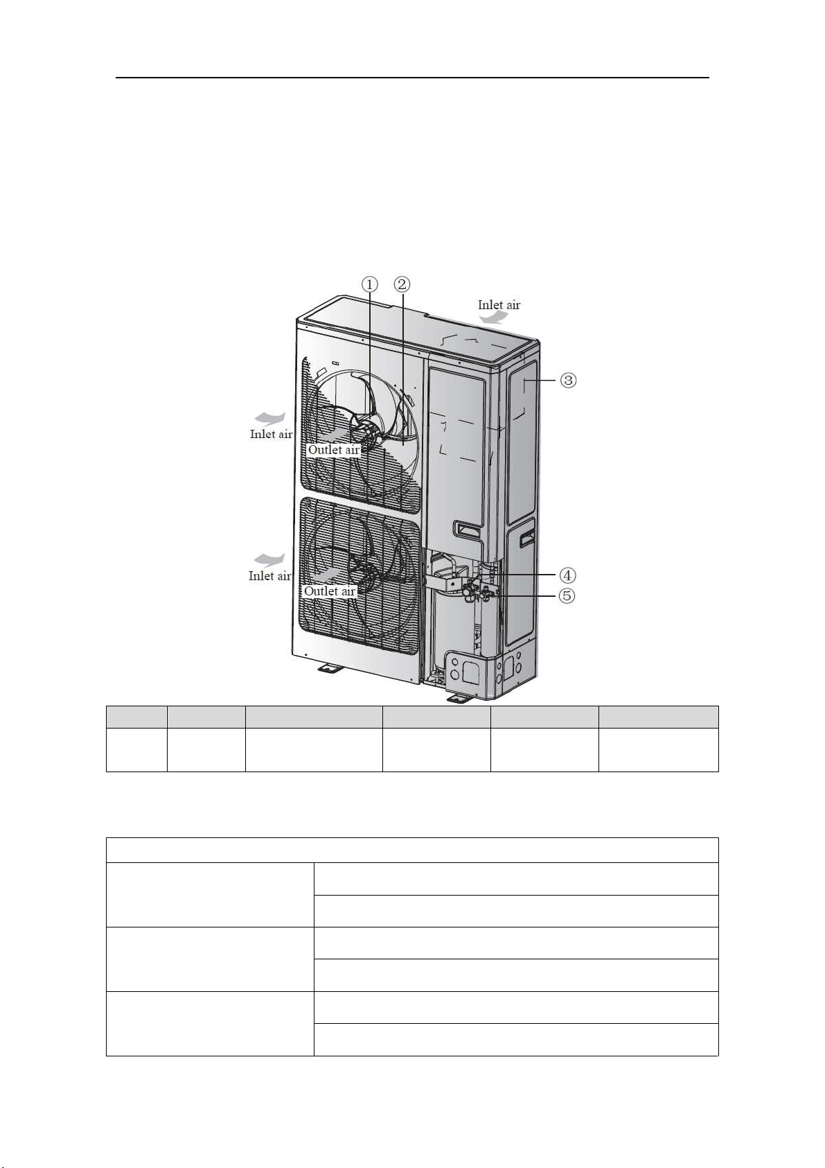
3.1 Names of Main Parts
NO. ① ② ③ ④ ⑤
Name Fan motor Axial flow fan blade Electrical box
Gas side stop
valve
Liquid side stop
valve
Fig. 1
3.2 Combinations for Outdoor and Indoor Units
Table 1
Sorts GWHD(56S)ND3CO
No. of indoor units to be
connected
Min 2
Max 9
No. of BU modules to be
connected
Min 1
Max 3
Total capacity of indoor units to
be connected(Btu/h)
Min 28000
Max 81000
Flex + Series
5
3.3 Parts and Components of Unit
For the Flex + Series, one outdoor unit is able to drive up to three BU modules and nine
indoor units which include cassette type, duct type, wall mounted type, floor ceiling type and
console type. The outdoor unit will run as long as any one indoor unit receives the running
command, and all indoor units stop once the outdoor unit is turned off.
Fig. 2
3.4 Working Temperature Range
Table 2
(BD :erutarepmet edistuO stroS ℃/℉)
Maximum cooling 48℃(118℉)
Minimum cooling -18℃(0℉)
Maximum heating 24℃(75℉)
Minimum heating -20℃(-4℉)
Outdoor unit
Power supply wire for outdoor
unit and BU module(3 wires)
Connection pipe
Transmission line(2 wires)
Power supply wire for
indoor unit(4 wires)
Ground
Power
(60Hz, 208/230V)
Power
(60Hz, 208/230V)
Power
(60Hz, 208/230V)
Power
(60Hz, 208/230V)
Ground
Ground
The 1st
branch
The 2nd
branch
BU 1
BU 2
BU 3
Indoor unit
Duct type
Duct type
Wall mounted
type
Wall mounted
type
Wall mounted
type
Cassette type
Cassette type
Floor ceiling
type
Console type
Ground
Flex + Series
6
4 Selection of Installation Location and Precautions
WAR N I N G
1) The installation of the air conditioner must be in accordance with the national and local laws and
regulations.
2) The quality of the installation will affect the capability of air conditioner directly. The installation
should be left to the appointed service center. Please contact your dealer after purchasing this machine.
Professional installation workers will provide installation and test services according to the installation
manual.
3) The air conditioner should not install in this place where the small animals exist, because they may
cause malfunctions, smoke or fire. Please keep the area around the unit clean.
4.1 Selection of Installation Location
WAR N I N G
1) The outdoor unit must be installed on a firm and solid support which can withstand the weight,
meanwhile the mounting surface must be horizontal plane. Otherwise, the unit would fall down and
cause injury or death.
2) The location must be out of children’s reach, please keep the unit away from children.
3) During installation, if the outdoor unit has to be exposed to strong wind, it must be fixed securely.
4) There is enough space for the installation and maintenance. Meanwhile, there is not any obstacle near
the air inlet and outlet of the indoor and outdoor units.
5) The place should be well-ventilated, so the machine can absorb and discharge sufficient air.
6) Avoid place the outdoor unit under the windows or between the constructions, hence to prevent normal
operating noise from entering the room.
7) When strong winds of 5 m/sec or more exist in the place of the installation, the outlet of the unit cannot
face the wind. If the wind blows against the outdoor unit's air outlet, it will cause deterioration of the
operational capacity and maybe break the fan.
8) Do not install in the place where there is heat source, flammable or explosive gas, a place subject to
severe dust, salty fog and polluted air.
9) Installation at the following places might lead to the air conditioner malfunction, such as where is full of
machine oil, saline-sodic soil near the sea, sulphide fog, high frequency facilities or special conditions.
If it is unavoidable, please contact the appointed service center.
NOTICE
1) It is better that do not install the unit where it will be exposed to direct sunlight. (If necessary, please
install a blind that does not interfere with the air flow.)
2) The unit should be free from getting dirty or getting wet by rain as much as possible
3) Outdoor unit shall be installed close to the indoor unit, hence to minimize the length and bends of
cooling pipe.
4) Do not place animals and plants in the path of the air inlet and outlet of the units.
5) Make sure that the unit will not cause any operating vibration or noise after installation.
Flex + Series
7
4.2 Outline Dimension of Outdoor Unit
Fig.
3 (unit: mm/inch)
4.3 Installation and Servicing Space
1) In case of installing only one unit
In case obstacles exist around the unit, the required installation space is in the Fig. 4.
2) In case of installing multiple units(2 units or more)
In case multiple rows of series installation, the required installation space is in the Fig. 5.
Fig. 4 (unit: mm) Fig. 5 (unit: mm)
Flex + Series
8
5 Installation Instruction
1) Check the installation location and ensure it is strength and level, so that the unit will not cause
any operating vibration or noise after installation.
2) In accordance with the foundation drawing in the following figure, please drill 4 holes in the
installation location.
A
: The outlet side B: Bottom view (mm) C: Drain hole
Fig. 6
3) Fix the unit securely with the foundation bolts. You can get the M10 or M12 foundation bolts,
nuts and washers from the market.
Fig. 7
4) Rub
ber or spring shock absorbers should be used during the installation of the outdoor unit to
meet the noise and vibration requirements.
5) Screw the foundation bolts into the ground and it is better that its length is less than 20mm
(4/5inch) from the foundation face.
Flex + Series
9
6 Installation of Refrigerant Pipes
6.1 Allowable Length and Drop Height of Connecting Pipe
Fig. 8 (8 indoor units)
Table 3
The sorts The pipes Length(m/feet)
Maximum
allowable
length
Total length between outdoor unit and BU
modules
L1+L2+L3+L4+L5 ≤55(181)
Total length between indoor units and
BU
1A+1B+1C+2A+2B+2C+
3A+3B
≤90(295)
Between indoor unit and BU module 1A;1B;1C;2A;2B;2C;3A;3B ≤15(49)
Between indoor unit and the 1st branch
L4+1B;L2+L5+2A;
L2+L3+3B
≤40(131)
Maximum
allowable
length
Between outdoor and indoor units H1 ≤30(99)
Between outdoor units and BU modules H2 ≤30(99)
Between BU and BU modules H3 ≤15(49)
Between indoor and indoor units H4 ≤15(49)
Minimum
allowable
length
Between outdoor and the 1st branch L1 ≥5(16)
Between BU and the branch L3;L4;L5
as possible as
short
NOTICE! BU module should be placed within the level between the outdoor unit and indoor
unit.
Flex + Series
10
6.2 Dimension of Connecting Pipe
Table 4
Sorts
Gas Pipe
(mm/inch)
Liquid Pipe
(mm/inch)
Outdoor unit
ISMO-6021
Φ15.9(5/8) Φ9.52(3/8)
Between outdoor unit and the
1st branch
The pipe L1 Φ19.05(3/4) Φ9.52(3/8)
Between the 1st and the 2nd
branch
The pipe L2 Φ15.9(5/8) Φ9.52(3/8)
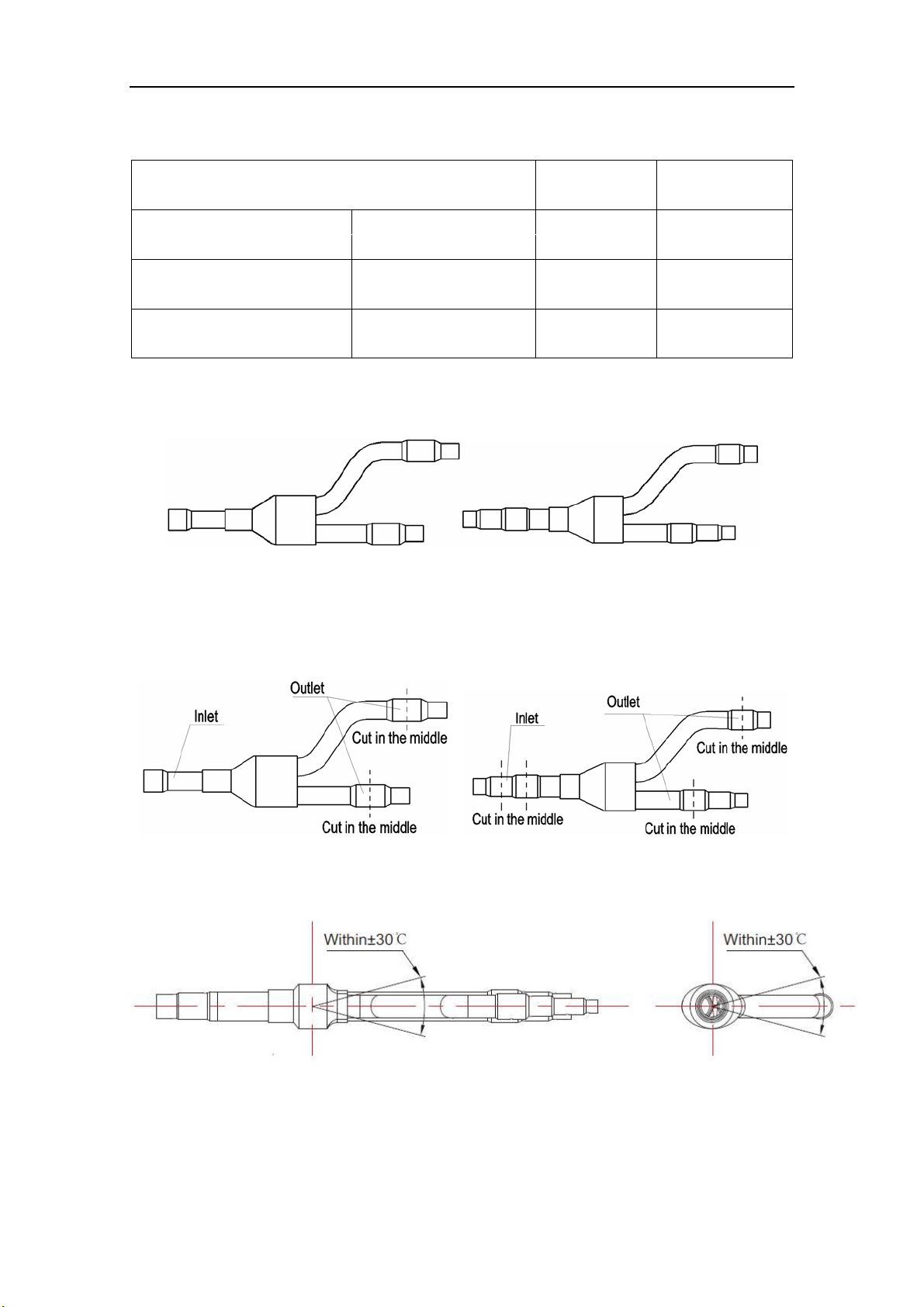
6.3 Connection of Branch Pipe
1) If two or three BU modules used, Y-type branch pipe of FQ01A/A will be chosen.
FQ01A/A (Liquid pipe) FQ01A/A (Gas pipe)
Fig. 9
2) Y-type branch pipe is equipped with auxiliary tubes to adjust the diameter of different pipes. If
the dimension of the pipe selected is different from the dimension of branch pipe joint, Cut the
copper tube in the middle with tube cutter and clear up burrs. Please do that as following figure.
Fig. 10
3) Y
-type branch pipe must be installed in vertical or horizontal direction. In the inlet of the branch
pipe, keep at least 500mm straight pipe.
Fig. 11
Flex + Series
11
6.4 Connection of Refrigerant Pipes
CAUTION
1) Conform to the following principles during pipe connection: Outdoor unit shall be installed close to the
indoor unit, hence to minimize the length and bends of connection pipes; the height gap of outdoor unit
and indoor units should be as small as possible; the radius of curvature should be as large as possible.
2) The brazing operation must be strictly in accordance with the process requirements. Rosin joint or pin
hole is not allowed.
3) During the installation, do not damage the pipeline. The pipeline’s radius of bending must be over than
200mm(8inch). The pipes cannot repeatedly be bent or straightened. Otherwise it will get harden and
crack. Do not bend or straight the pipes for more than 3 times at the same position.
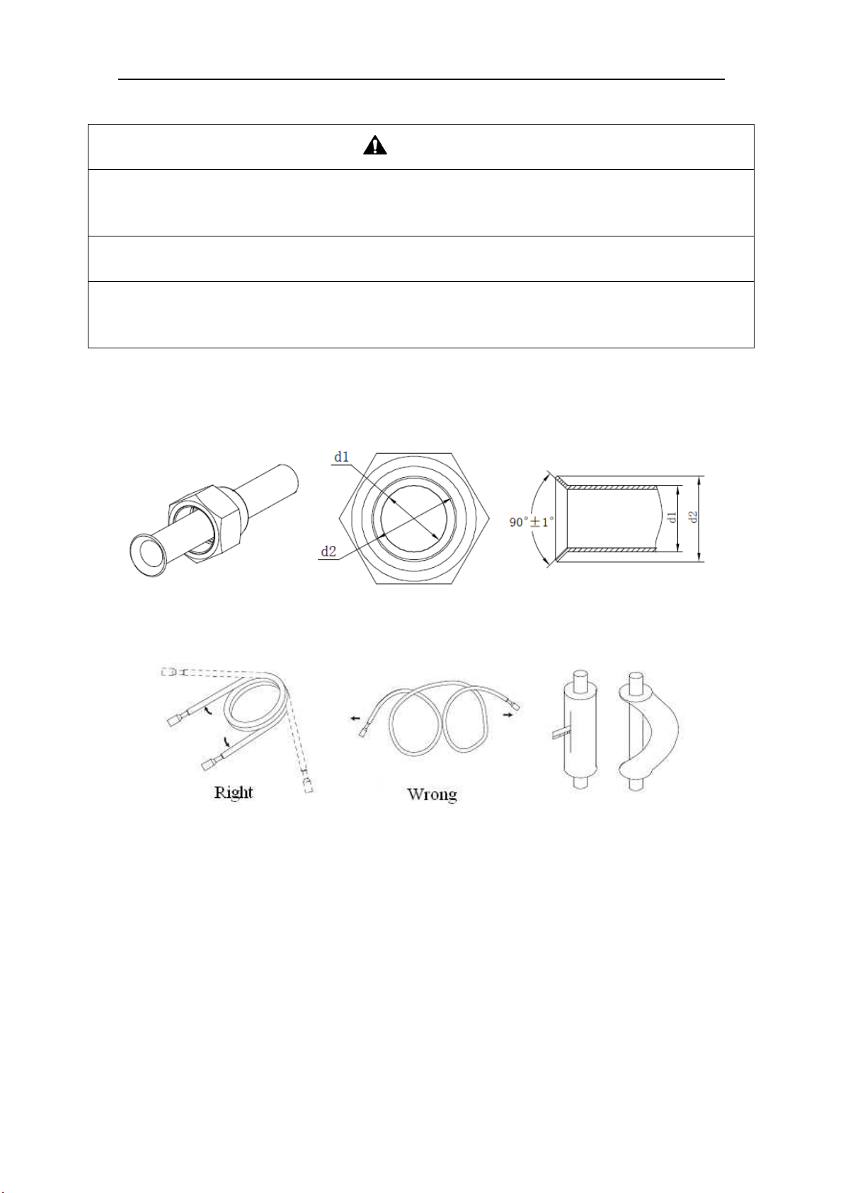
1) The process of flaring
① Using the tube cutter to cut the connecting pipe in the appropriate place and remove the burrs.
② Install the nut before the flaring operation.
③ Check the flared portion, whether there is fractured or not.
Fig. 12
2) Precaution for elbow operation
① The elbow operation could be done by hands. Be careful and do not damage the pipe.
Fig. 13
② If the thermal insulation of the refrigerant pipe is not removed, please do not bend the pipe.
Otherwise, it maybe leads the pipe to crack. It is better to make an incision with a knife in the
thermal insulation and removes it. After elbow operation is finished, recover the thermal
insulation with binding band.
3) The process of install refrigerant pipes
① Remove the screw caps from the pipes.
② Align the flared end of copper tube with the center of pipe joint. Tighten the nuts by hands. (If
the flared end of copper tube and the center of pipe joint are not in coaxial, it is hard to tighten
the nuts by hands, please do not tighten it with spanners, because the screw thread may be
broken by force).
③ Tighten the flaring nuts with torque wrench until you hear a “click”. (The spanner and torque
Flex + Series
12
wrench should be perpendicular to the refrigerant pipeline).
④ The following table for the torque required to tighten the nuts.
Table 5
Pipe
diameter
(mm/inch)
Thickness of
copper
tube(mm/inch)
Tightening
torque
(N·m/1bf·ft)
Φ6.35(1/4) ≥0.8(1/32) 15~30(11~22)
Φ9.52(3/8) ≥0.8(1/32) 35~40(26~29)
Φ12.7(1/2) ≥0.8(1/32) 45~50(33~37)
Φ15.9(5/8) ≥1.0(1/25) 60~65(44~48)
Φ19.05(3/4) ≥1.0(1/25) 70~75(52~55)
Fig. 14
CAUTION
1) During the connection of the indoor unit and BU module to the refrigerant pipe, never pull any joints of
the indoor unit and the BU module by force; otherwise the capillary pipe or other pipe may crack,
which then would result in leakage.
2) The refrigerant pipe should be supported by brackets, that is, don’t let the unit withstand the weight of
it.
3) For the Flex + Series, each pipe should be labeled to tell which system it belongs to avoid
mistaken inaccurate piping.
6.5 Connection of Refrigerant Pipe
Flex + Series
13
NO. ① ② ③ ④
Name Coping plate Rear side plate Front side plate Gas side stop valve
NO. ⑤ ⑥ ⑦
Name Liquid side stop valve Right connection board Front connection board
NO. A B C D
Name Front connection Bottom connection Side connection Rear connection
Fig. 15
1) Unscrew the coping plate, front side plate, right connection board and front connection board.
2) The refrigerant pipes can be installed in four directions, please choose the proper direction.
3) Knock the holes in the plate of the chosen direction with the drill and hammer.
4) Connect the pipes to the stop valves.
5) Bend the pipes to go through the knockout holes.
6) Cover the through-holes with sealing materials to prevent the water, dust or small animals going
into the outdoor unit.
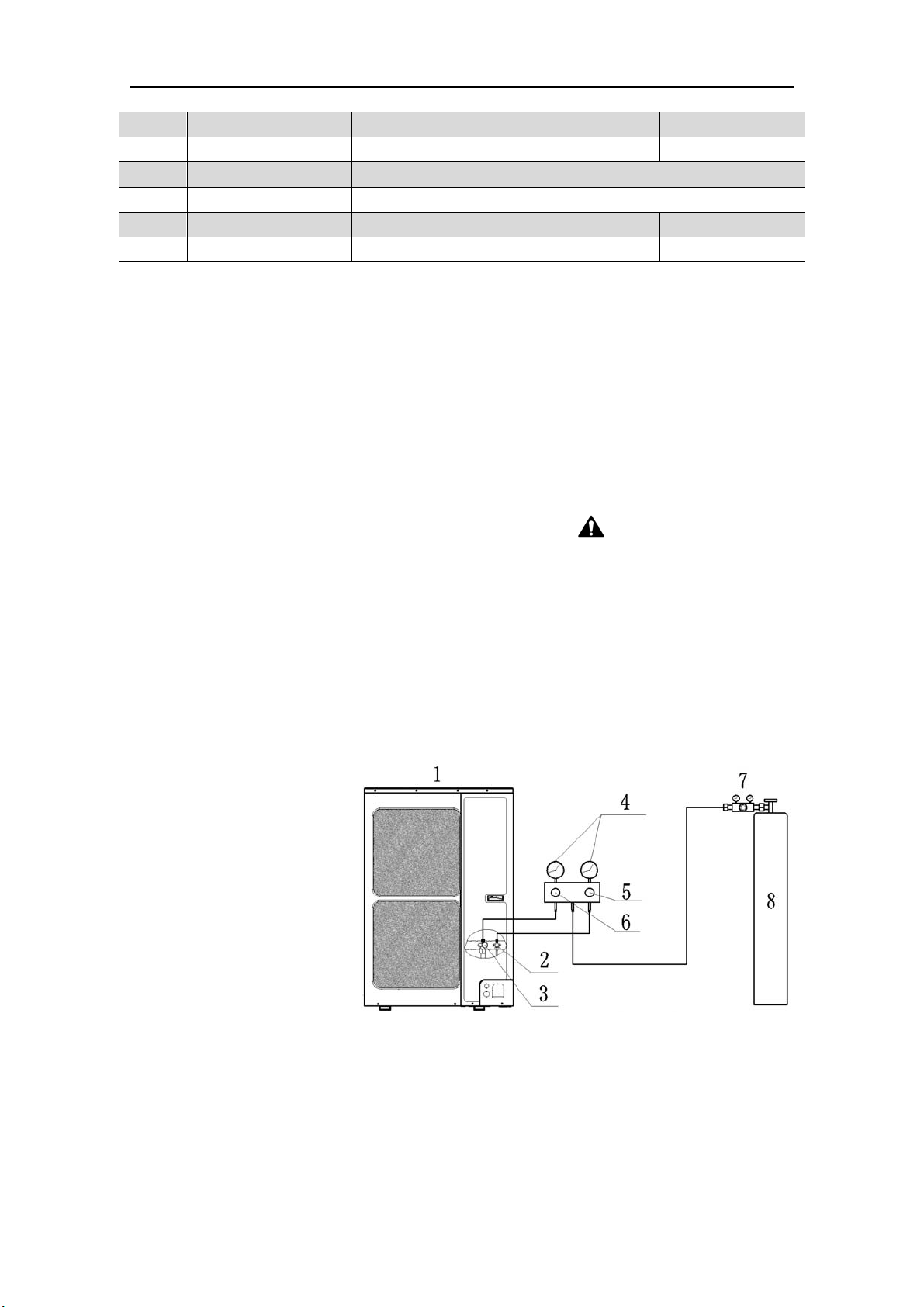
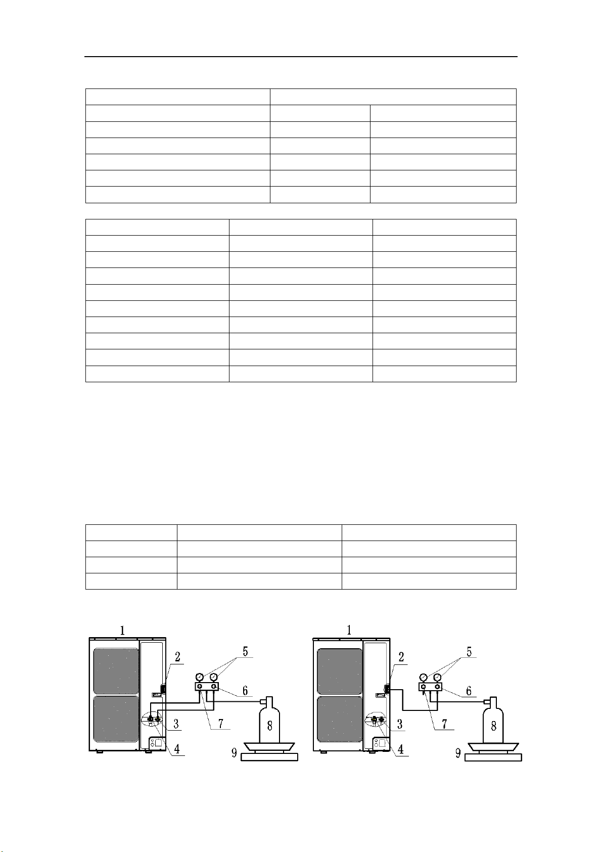
6.6 Leak Test
1) Please make sure that the stop valves of the outdoor unit are closed during the operation.
2) The leak test should be made by pressurizing nitrogen gas.
WARNING! Do not mix
oxygen, C
2
H
2
or other dangerous gas into the refrigerant circuit.
3) Turn on the Hi-knob and Lo-knob.
NOTICE! The leak test should be done simultaneously
at both the gas and liquid stop valves.
4) Open the pressure reducing valve, pressurize the connection pipes to 1.0 MPa (10 bar) slowly,
wait fifteen minutes, and make sure that the pressure will not drop.
5) Rise the pressure to 4.0 MPa (40 bar) slowly, wait 24 hours and make sure the pressure will not
drop
6) If the pressure does not decrease, the pipes have passed the test. Otherwise, look for where the
gas leaks from.
1: Outdoor unit
2: Liquid side stop valve
3: Gas side stop valve
4: Pressure-vacuum gauge
5: Hi-knob
6: Lo-knob
7: Pressure reducing valve
8: Nitrogen
Fig. 16
6.7 Vacuum Operation
1) Make sure the stop valves of the outdoor unit are closed fully during the operation.
2) As shown in the following figure, expel the gas from the refrigerant pipes by the vacuum pump.
3) Open the pump and turn on the knobs to evacuate the gas in the liquid and gas pipes.
NOTICE!
The vacuuming should be done simultaneously at both the gas and liquid stop valves.
4) When the pressure of the system is less than -0.1Mpa (-1bar), keep the system for more than
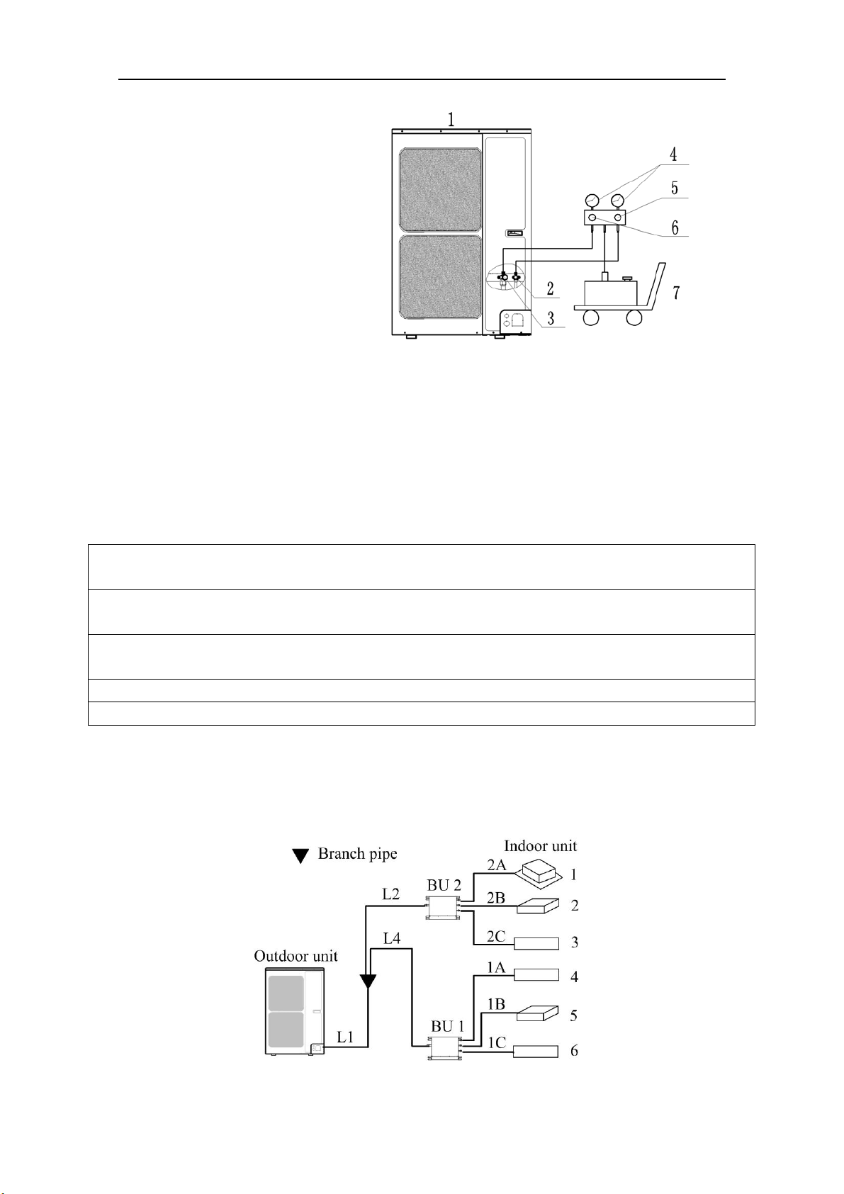
Flex + Series
14
one hour under the condition.
1: Outdoor unit
2: Liquid side stop valve
3: Gas side stop valve
4: Pressure-vacuum gauge
5: Hi-knob
6: Lo-knob
7: Vacuum pump
Fig. 17
5) Turn off the knobs firstly and then the pump, and if the pressure of the pressure-vacuum gauge
does not rise within 2 hours, the system is under a vacuum. Otherwise, the system has leaked,
please look for where the gas leaks in.
6.8 Refrigerant Charging
The refrigerant has been charged into the outdoor unit before shipped from the manufacturer,
while additional refrigerant still need be charged into the refrigerant pipe in the field installation.
6.8.1 Calculation of the Additional Refrigerant Charging
1) G
et the refrigerant charge of the outdoor unit from the nameplate.
NOTICE
1) The refrigerant charge of the outdoor unit does not include the charged additionally in the indoor unit,
BU module and the refrigerant pipe.
2) For the length of the connecting pipe is decided on the field, the amount of additional refrigerant shall
be decided depending on the dimension and the length of the liquid pipe used on the field.
3) It does not need to add refrigerant if the total length of liquid pipe is within 30m (98-3/8feet).
4) Record the amount of additional refrigerant for convenience of future maintenance.
2) Calculating the Mass of Additional Refrigerant
Additional Refrigerant Charge (kg/oz) = Σ the Liquid Pipe Length of Φ6.35 × 0.022kg/m
(0.020oz/inch)+
Σ the Liquid Pipe Length of Φ9.52×0.054kg/m (0.048oz/inch)-1.47kg(51.86oz)
NOTICE! If the additional refrigerant charge is negative, it does not need to add refrigerant.
3) Example:
GWHD(56S)ND3CO
Fig. 18
Flex + Series
15
Table 6
Serial No. Model
Indoor unit 1 Cassette type
ISMI-C15
Indoor unit 2 Duct type N/A
Indoor unit 3 Wall mounted type
ISMI-W092
Indoor unit 4 Wall mounted type
ISMI-W092
Indoor unit 5 Duct type N/A
Indoor unit 6 Wall mounted type
ISMI-W092
Table 7
Serial Diameter(mm/inch) Length(m/feet)
L1 Φ9.52(3/8) 20(65-5/8)
L2 Φ9.52(3/8) 10(32-3/4)
L4 Φ9.52(3/8) 10(32-3/4)
1A Φ6.35(1/4) 5(16-3/8)
1B Φ6.35(1/4) 5(16-3/8)
1C Φ6.35(1/4) 5(16-3/8)
2A Φ6.35(1/4) 5(16-3/8)
2B Φ6.35(1/4) 5(16-3/8)
2C Φ6.35(1/4) 5(16-3/8)
The total length of the liquid pipes: 20+10+10+5+5+5+5+5+5=70m (229-5/8feet).
Thus, the total length is over than 30m (98-3/8feet), so the air conditioner needs to add refrigerant.
Additional refrigerant charge
Σ the Liquid Pipe Length of Φ6.35×0.022kg/m +Σ the Liquid Pipe Length of Φ9.52×0.054kg/m
-1.47kg
=(5+5+5+5+5+5)(m)×0.022kg/m+(20+10+10)(m)×0.054kg/m-1.47kg
=1.35kg (47.63oz)
4) Additional refrigerant charge record for future maintenance
Table 8
Diameter(mm) Total length(m/feet) Additional refrigerant charge(kg/oz)
Φ6.35(1/4)
Φ9.52(3/8)
Total
6.8.2 Proced
ures for adding refrigerant
Flex + Series
16
NO. 1 2 3 4 5
Name
Outdoor
unit
Service port
Liquid side stop
valve
Gas side stop
valve
Pressure-vacuum
gauge
NO. 6 7 8 9
Name Hi-knob Lo-knob R410A tank Scale
Fig. 19
1) When the liquid and gas stop valves have not been opened, the system is under the vacuum:
① Refer to the left of the figure above; connect the R410A tank to the system.
② Turn on the R410A tank and the Hi-knob; charge the R410A refrigerant into the unit from the
liquid side stop valve. The Lo-knob should be closed completely.
③ Turn off the R410A tank and the Hi-knob immediately, when the adding refrigerant is enough.
④ Turn on the liquid and gas side stop valves in an anticlockwise direction slowly and completely.
2) If the pressure of the system is too high to charge refrigerant, you can do as follow.
① Turn on the liquid and gas side stop valves in an anticlockwise direction slowly and completely.
② Turn on the power of the air conditioner, and set cooling mode, running more than 0.5h when
outside temperature is higher than 15℃(59℉) DB.
a) Refer to the left of the figure above; connect the R410A tank to the system.
b) Turn on the R410A tank and the Lo-knob; charge the R410A refrigerant into the unit from
the gas side stop valve. The Hi-knob should be closed completely.
c) Turn off the R410A tank and the Lo-knob immediately, when adding refrigerant is enough.
③ Turn on the power of the air conditioner, and set heating mode, running more than 0.5h when
outside temperature is lower than 15℃(59℉) DB.
a) Refer to the right of the figure above; connect the R410A tank to the system.
b) Turn on the R410A tank and the Hi-knob; charge the R410A refrigerant into the unit from
the service port. The Lo-knob should be closed completely.
c) Turn off the R410A tank and the Hi-knob immediately, when adding refrigerant is enough.
CAUTION
1) Make sure that the liquid and gas side stop valves are opened completely after the installation.
2) Make sure that the length of liquid pipe is exactly.
3) Additional refrigerant charge must be measured exactly.
4) Make sure that the refrigerant which charge into the unit is in liquid state.
5) Please prevent the refrigerant leakage away from your body when remove the charging hose.
6) Please heat the refrigerant tank with hot water or hot air when the outside temperature is too low.
However, it must be forbidden to heat with fire directly, otherwise it may lead to explosion.
Flex + Series
17
7 Electrical Wiring Work
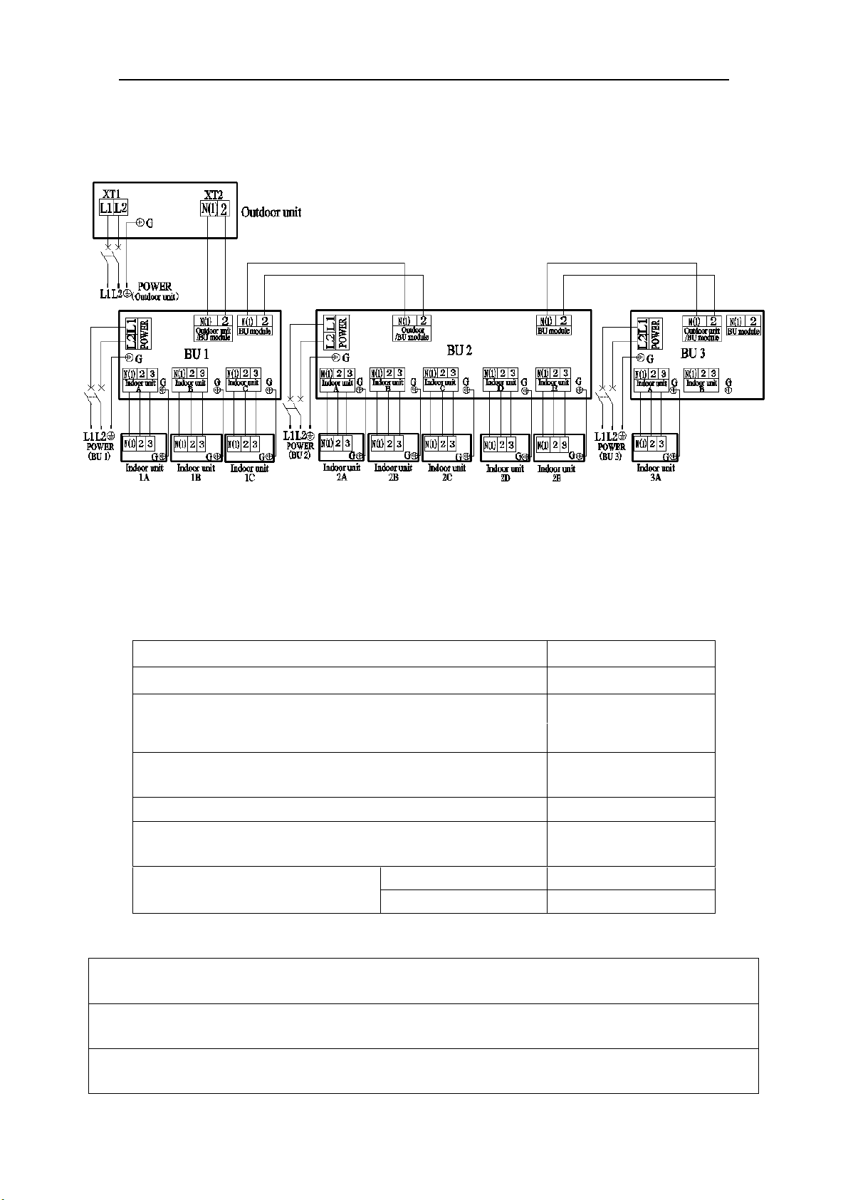
7.1 Wiring Connection
NOTICE! The “L1”, “3” terminals are connected to the live wire, the “L2”,”N(1)” terminals
are connected to the neutral wire and the ”2” terminal is connected to the transmission line.
Fig. 20
7.2 Requirements of Power Circuit and Cable
Table 9
Phase and frequency 1Ph,60Hz
Voltage 208/230V
Recommended cable of outdoor unit (Pieces × Sectional area)
3×6.0 mm
2
Recommended cable of BU module
(Pieces × Sectional area)
3×0.75 mm
2
Transmission line (Pieces × Sectional area) 2×1.5 mm
2
Recommended cable of indoor unit
(Pieces × Sectional area)
4×0.75mm
2
Capacity of the air switch
ISMO-6021
40A
BU module 10A
NOTICE
1) The total length of the transmission line between the outdoor unit and the furthest BU module is not
more than 55m (180feet). Otherwise, the system cannot work possibility.
2) The specifications of the power cable and transmission line listed in the table above are determined
based on the maximum power (maximum amps) of the unit.
Flex + Series
18
3) The specifications of the power cable listed in the table above are applied to the conduit-guarded
multi-wire copper cable (like, YJV copper cable, consisting of PE insulated wires and a PVC cable
jacket) used at 40℃(104℉) and resistible to 90℃(194℉), and shall be at least those of ordinary
polychloroprene sheathed cords. If the working condition changes, they should be modified according
to the related national standard.
4) The specifications of the air switch listed in the table above are applied to the breaker with the working
temperature at 40℃(104℉). If the working condition changes, they should be modified according to the
related national standard.
5) The length of the recommended power cable should be less than 15meters (49feet); otherwise, the
diameter of the power cable is not enough.
6) Mentioned power cable and transmission line length is just a reference value. It may be different
depending on the condition of installation, humidity or materials, etc.
7) An all-pole disconnection switch having a contact separation of at least 3mm in all poles should be
connected in fixed wiring.
7.3 Ground Requirements
WAR N I N G
1) The air conditioner is classified into the Class I appliances, so its ground ways must be reliable.
2) The ground wire must be fixed on the screw hole with the sign as the right figure.
3) The yellow-green wire of the air conditioner is the ground wire and must be fixed by the tapping screw.
And it cannot be used for other purpose or cut off. Otherwise, it will cause the hazard of electric shock.
4) The reliable ground terminal should be provided and the ground wire cannot be connected to any of the
following places: a. Water pipe; b. Coal gas pipe; c. Sewage pipe; d. Lightning rod
e. Telephone line f. Other unreliable places considered by a professional.
7.4 Precautions on the Electrical Wiring Work
WAR N I N G
1) The electrical installation should be carried out by the professional as instructed by the local laws,
regulations and also this manual.
2) The ground connection should be reliable and the ground wire should be connected to the dedicated
device of the building by the professional.
3) Before starting work, the power must not be supplied to the unit.
4) The air switch coupled with the leakage current protection switch must be equipped in the circuits,
which is of enough capacity and of both magnetic and thermal tripping functions in case of the short
circuit and overload.
5) The electrical work should use a cable length enough to cover the entire distance with no connection. If
it is unavoidable, please make sure the connection should be reliable, the external forces will not act on
the wires and the joint is not bared. Otherwise it will cause electrical shock or fire etc.
6) The power cable with the rated voltage and exclusive circuit for the air conditioner should be used.
7) Do not pull the power cable by force after it is installed.
8) The diameter of the power cable should be large enough and once it is damaged, it must be replaced by
the dedicated one.
9) The multi-wire copper cable should be used for the power cable and the transmission line.
Flex + Series
19
7.5 Precaution of Laying Wires
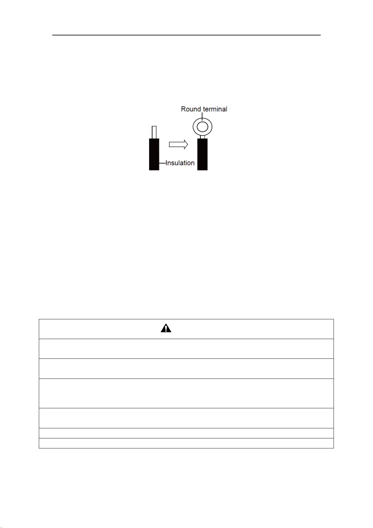
1) Use a wire stripper to strip off a length of the insulation layer at the end of the wires;
2) Loosen the screws on the terminal block of the air conditioner;
3) Press the ends of the cable tightly onto the round terminals corresponding to the size of the
screws.
4) Pass the screw through the round terminals and fix it onto the terminal block.
Fig. 21
7.6 Procedures for Electrical Wiring Work
1) Knock the holes in the plate of the chosen direction with the hammer.
2) Place the rubber ring on the knockout hole.
3) Let the power cable and transmission line go through the knockout hole.
4) Connect the power cable of the outdoor unit to the L1, L2 terminals with the sign of the XT1
and as well as the ground screw.
5) Connect the transmission line of the outdoor unit to the N(1), 2 terminals with the sign of the
XT2.
6) Fix the power cable and transmission line firmly by cable fixing clip. In order to protect the
power cable and transmission line from damage by the pipes or others, an interval of at least
2cm (3/4inch) away is essential.
7) Screw the coping plate, front side plate, right connection board, front connection board back.
8) Cover the through-holes with sealing materials to prevent the water, dust or small animals going
into the outdoor unit.
CAUTION
1) The transmission line and the power cable must be separated with an interval of at least 2cm (3/4inch);
otherwise it may be result in communication problem.
2) In order to protect the power cable and transmission line from damaging by the knockout hole, the
rubber ring must be placed on the hole. Otherwise, it may cause electrical shock or fire etc.
3) The power wire and transmission line must be more than 1 meter (3-1/4feet) away from televisions or
radios which can emit electromagnetic waves to prevent image interference or noise. Otherwise, the unit
maybe cannot work.
4) Confirm the each cable connected to the terminal screw is exactly and securely after finishing the
electric work.
5) Fix each ground wire separately with the ground screw.
6) If the connecting wire is connected to the terminal incorrectly, it may cause a fire.
Flex + Series
20
8 Design of Drainage Pipeline
8.1 Installation of Drain Hose
1) Choose one drain hole in the bottom of the outdoor unit.
2) Connect the drain hose to the drain hole.
3) The drain hose should be kept at 5~10 degrees of gradient to facilitate discharge of the
condensing water. Take care that does not exert too much force on the hose.
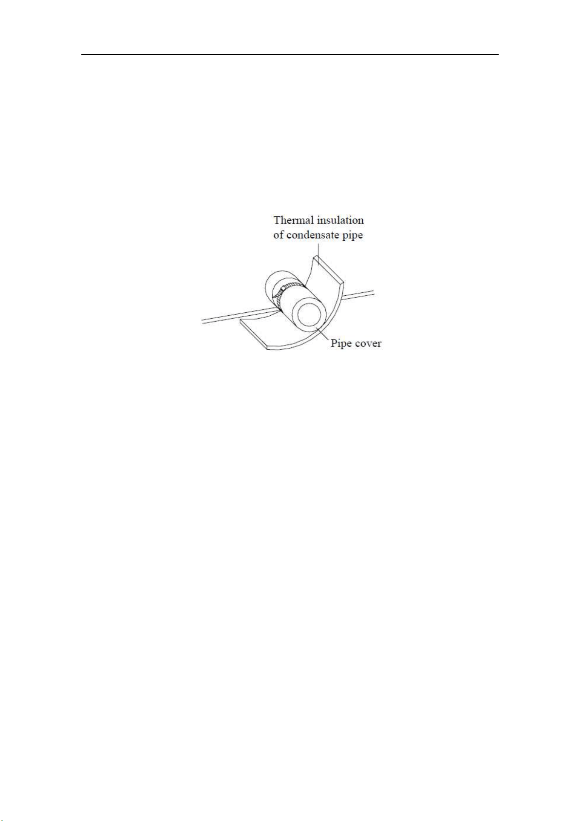
4) Thermal insulation materials should be placed at the joints of the drain hose so as to prevent
from dew condensation. Fix the drain hose firmly by binding band.
Fig. 22
5) The
end of the drain hose should be inserted into the hole of drainage pipeline.
8.2 Design of Drainage Pipeline
1) The drainage pipeline should be kept at a certain gradient (1/50—1/100) so as to avoid bulges
of pipes where there might be water bends.
2) The drainage pipeline is form of the hard PVC pipes for common purposes which can be
purchased locally. The diameter of the PVC pipes is not less than 17mm (11/16inch) and the
pipeline should be fixed as close to the BU module as possible.
3) Insert the drain hose into the drain hole of drainage pipeline. Use binding band to fix it tightly.
It is not allowed to use adhesive glue to join the drain hose to the drainage hole.
4) When
the drainage pipeline is laid for a couple
of units, the position of the shared pipeline
should be approximately 100mm lower than the drainage hole of each module. In this case,
some special-purpose pipes with thicker walls will be used.
NOTICE! At intervals of about 1 meter (3-1/4feet), fix the drain pipes to the wall with
brackets, not floating in the air.
Flex + Series
21
9 Installation of Protective Layer
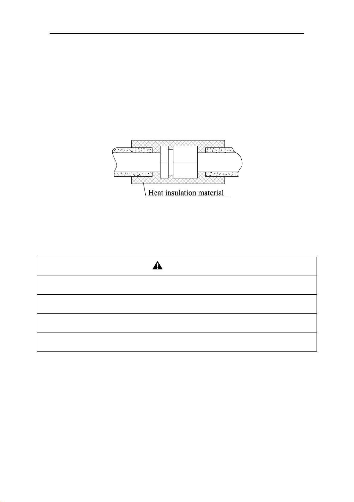
1) The refrigerant pipes should be insulated by the heat insulation material and plastic tape in
order to prevent water condensation and leakage.
2) Do not use the foam on the branch pipe as the material for heat insulation, heat insulation
material of branches should be the same as that of the pipeline.
NOTICE! The heat resistance of heat insulation material should be over than 120
℃(248℉)
and its thickness is more than 9mm(3/8inch).
3) The joints of the system should be wrapped with the heat insulation material and no gap is
allowed on the joint of the system, as shown in the following figure.
Fig. 23
4) Bun
dle the refrigerant pipe and transmission line together with tape, and separate them from the
drain pipe to prevent the condensate water overflowing.
5) Wrap the pipe from the bottom of the outdoor unit to the top of the pipe where it enters the wall.
During the wrapping, the later circle should cover half of the former one.
CAUTION
1) At intervals of about 1 meter (3-1/4feet), fix the refrigerant pipes to the wall with brackets, that is, don’t
let the unit withstand the weight of it or float it in the air.
2) After the pipe is protected well enough, never bend it to form a small angle(<90°), otherwise it would
crack or break.
3) Do not wrap the refrigerant pipes very tight, otherwise the insulation effect would be weakened.
Additionally, make sure the drain hose is separated from the refrigerant pipes.
4) After that, cover the hole on the wall with sealing materials to prevent wind and noise going into the
room.
Flex + Series
22
10 Test Operation
10.1 Check after Installation
Table 10
Items to be checked Possible malfunction
Has it been fixed reliable? The unit may drop, vibrate or make noise.
Has the gas leakage been checked? It may cause insufficient cooling(heating) capacity.
Is the thermal insulation of the unit sufficient? It may cause condensation and dripping.
Is the drainage well? It may cause condensation and dripping.
Is the voltage in accordance with the rated
voltage marked on the nameplate?
It may cause electric malfunction or the
components may be burned out
Are the lines and pipelines correctly installed?
It may cause electric malfunction or the
components may be burned out
Has the unit been safely grounded? It may cause electrical leakage.
Are the models of lines in conformity with
requirements?
It may cause electric malfunction or the
components may be burned out
Are there any obstacles near the air inlet and
outlet of the indoor and outdoor units?
It may cause insufficient cooling(heating) capacity.
Have the length of connection pipes and
refrigerant charge amount been recorded?
It is not easy to decide the charge amount of
refrigerant.
10.2 Test Operation
1) Before test operation
The appearance of the unit and the refrigerant pipes cannot be damaged during the installation.
Do not switch on power before installation is finished completely.
Electrical wiring must be connected correctly and securely.
The stop valves of the outdoor unit should be opened fully.
All the impurities such as scraps and thrums must be cleared from the unit.
2) Test operation method
① The test operation should be carried out by the professionally skilled personnel on the premise
that all items listed above are in normal conditions.
② Set the status of the power supply switch as “ON” eight hours before the start of operation
③ Press mode button, to select the COOL, or HEAT. Whether the air conditioner is work
normally or not.
The fan motor of the indoor unit will run automatically in one minute.
The fan motor and compressor of the outdoor unit will run automatically in one minute.
④ Make sure that every combination of indoor units can work well.
WAR N I N G
If the unit cannot work nor has any abnormal noise after the compressor is started, turn off the unit for an
immediate check.
Flex + Series
23
11 Testing Board Introduction
11.1 Compose of the Testing Board
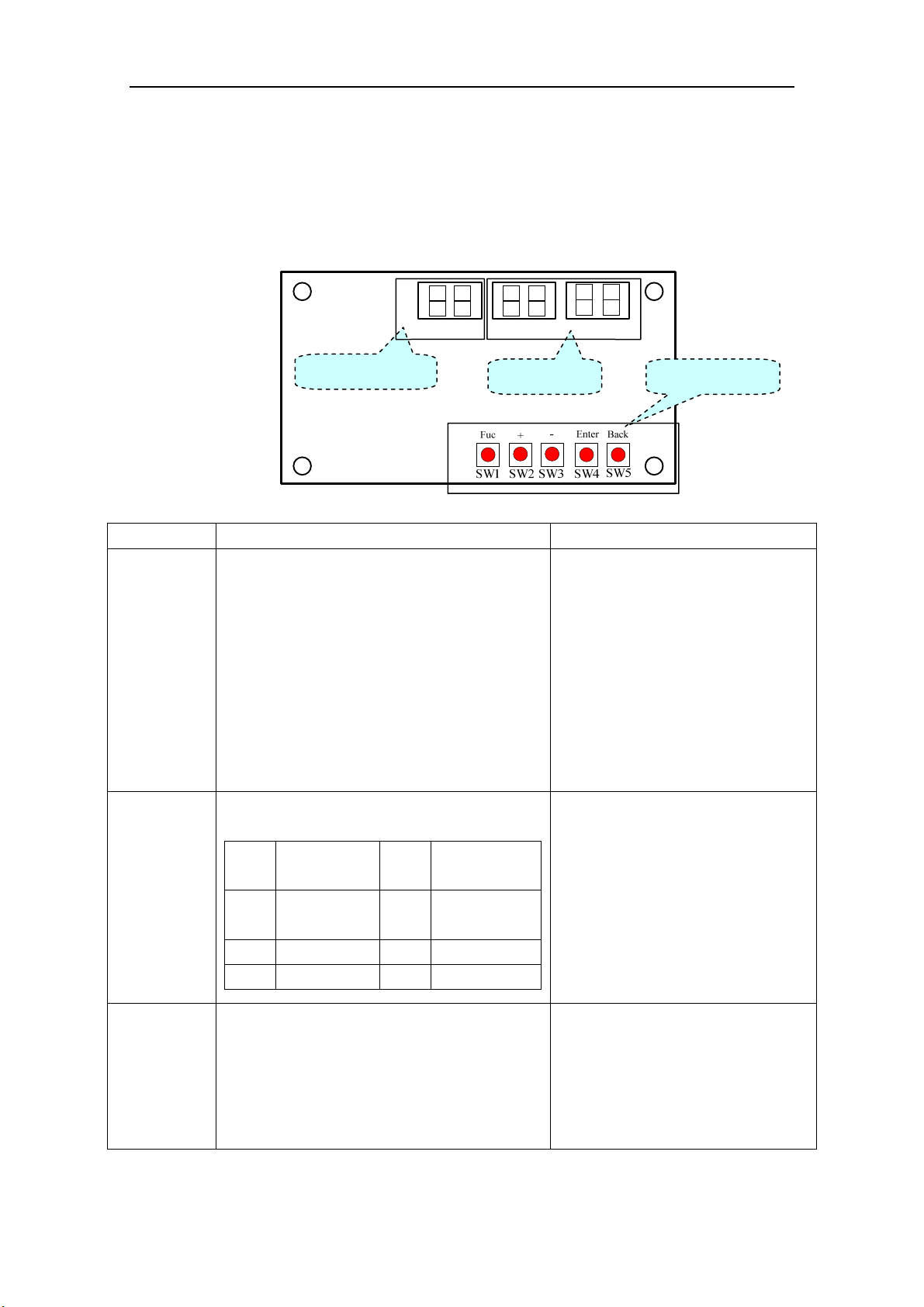
The testing board is in front of electrical box and can be observed well. It has several following
advantages: detect indoor unit numbers and indoor unit address, displays real running function and
error code automatically. It is composed of the function section, data section and button section.
11.2 Instruction of Function and Data Section
Running state The display of function section The display of data section
Stop
① The section will display the numbers of the
indoor units which have established
communication with the outdoor unit. For
example, if there are seven established indoor
units, the section will display “7”.
② It will display the address of the indoor units
by turns. For example, the “1b” is represented
of the indoor unit 1B.
(BU module:1/2/3,Indoor unit: A/b/C/d/E)
① If the function section displays the
numbers of the indoor units, the data
section will display the outside
temperature. For example, the “35” is
represented of 35℃.
② If the function section displays the
address of the indoor unit,the data
section will display the model of the
indoor unit, for example, the “35” is
represented of 35 model.
Normal
The code of running state:
Code
Running
state
Code Running state
UE
Pressure
equalization
UH Heating
UP Pump down F7 Oil returning
UC Cooling H1 Defrosting
It displays the target gear of the
compressor. If the gear is zero, it will
display “0”. For example, the gear is
the fifteenth; it will display “15”. The
range of the gear is from 0 to 60.
Malfunction
If the malfunction occurs in the system, the
section will display the error code. If there are
several malfunctions, it will display the error
codes by turns at intervals of 2 seconds.
① If the malfunction occurs in the
outdoor unit, the section displays
nothing;
② If the malfunction occurs in the
indoor units, the section displays the
address of the indoor unit.
Function section
Data section Button section
Flex + Series
24
12 Troubleshooting
WAR N I N G
1) In the event of abnormal conditions (like, stinky smell), please shut off the power supply immediately
and then contact the appointed service center; otherwise, the abnormal running would damage the air
conditioner and also would cause electric shock or fire hazard .
2) Do not repair the air conditioning personally but instead contact the professionally skilled personnel at
the appointed service center, as the incorrect repair would cause electric shock or fire hazard etc.
12.1 Check before Contacting Service Center
Please check the following items before contacting the maintenance serviceman.
Conditions Causes Corrective actions
The unit does not
run at all
Broken fuse or breaker is off
Replace the damaged fuse or
close the breaker
Power off
Restart the unit after power
supply resumes
Power supply plug is loose Plug the power supply properly
The batteries voltage of the remote
controller is insufficient
Replace with new batteries
Remote controller is out of the control
scope
The distance shall be within 8m
The unit stops
soon after it starts
Air inlet or outlet of indoor unit or
outdoor unit is blocked
Remove the obstacles
Cooling or heating
is abnormal
Air inlet or outlet of indoor unit or
outdoor unit is blocked
Remove the obstacles
Temperature setting is improper
Adjust the setting of remote
controller or wire controller
Air speed is set too low
Adjust the setting of remote
controller or wire controller
Improper airflow direction
Adjust the setting of remote
controller or wire controller
Door or window is open Close the door or window
Under direct sunshine
Hang curtain or blinders over the
window
Too many people in the room
Too many heat sources indoors Reduce the heat sources
The filter screen is dirt or blocked Clean the filter screen
NOTICE! If the air conditioner still runs abnormally after the above check and handling,
please contact the local appointed service center and also give a description of the error
occurred as well as the model of the unit.
Flex + Series
25
12.2 Problem Handling
The conditions listed below are not classified into errors.
Conditions Causes
The unit does
not run
When restart the unit soon after
it is stopped
The overload protection switch of the unit let
the startup delayed for three minutes
As soon as power supply is on
The unit will stand by for approximate one
minute
The unit blows
out mist
When the cooling operation
starts
The hi-humidity air indoor is cooled quickly
The unit
generates noise
The unit “clatters” as soon as it
starts running
It is the sound generated during the
initialization of the electronic expansion
valve
The unit “swishes” during the
cooling operation
It is the sound when the refrigerant gas runs
inside the unit
The unit “swishes” when it is
started or stopped
It is the sound when the refrigerant gas stops
running
The unit “swishes” when it is in
and after the running
It is the sound when the draining system is
operating
The unit “squeaks” when it is in
and after the running
It is the sound of frication generated by the
skin plate etc which swells due to the
temperature change
The unit blows
out dust
When the unit restarts after it is
not used for a long time
The dust inside the unit is blown out again
The unit emits
odors
When the unit is running The odors absorbed in are blown out
12.3 Error Description
If some error occurs when the unit is running, the error code will be displayed and check for
more details about the meaning of each error.
Errors of definition
Main control display for outdoor unit
Indoor
unit code
Testing
board code
Yellow LED Red LED Green LED
The compressor is startup Flash 1 time
IPM current protection Flash 3 times
H5 H5
IPM temperature protection Flash 5 times
P8 P8
PFC current protection Flash 7 times
HC
PFC temperature protection Flash 8 times
P8 P8
Low voltage protection Flash 9 times
PL PL
High voltage protection Flash 10 times
PH PH
Low pressure protection Flash 11 times
E3
High pressure protection Flash 12 times
E8
High pressure switch protection Flash 13 times
E1
Capacitor charging error Flash 14 times
PU
AC current protection Flash 15 times
E5 E5
Flex + Series
26
Memory card error Flash 16 times
EE
Compressor demagnetizing
protection
Flash 17 times
HE HE
Compressor desynchronizing Flash 18 times
H7 H7
Compressor phase lack Flash 19 times
U2 U2
Compressor phase circuit detection
error
Flash 20 times
U1 U1
Compressor power protection Flash 21 times
L9 L9
Compressor overload protection Flash 22 times
H3 H3
Compressor discharge temperature
protection
Flash 23 times
E4 E4
Lack of refrigerant or jam protection Flash 31 times
F0 F0
Normal operation Flash 1 time
Frequency limitation for AC current Flash 2 times
F8
Oil returning Flash 3 times
F7
Defrosting Flash 4 times
H1 H1
Frequency limitation for IPM
temperature
Flash 5 times
EU
Frequency limitation for PFC
temperature
Flash 6 times
EU
Frequency limitation for compressor
overload
Flash 8 times
LU
Frequency limitation for compressor
discharge temperature
Flash 9 times
F9
Frequency limitation for low pressure Flash 10 times
Pn
Frequency limitation for high
pressure
Flash 11 times
F6
Discharge temperature sensor error Flash 12 times
F5 F5
Outdoor temperature sensor error Flash 13 times
F3 F3
Suction temperature sensor error Flash 15 times
dc
Condenser temperature sensor error Flash 16 times
A7 A7
Sub-cool temperature sensor error Flash 17 times
bC
Low pressure sensor error Flash 18 times
dL
High pressure sensor error Flash 19 times
e1
Fan motor error for indoor unit Flash 20 times
H6 H6
Driving board is connected Flash 1 time
Testing board is connected Flash 2 times
Computer is connected Flash 4 times
Indoor unit 1 is connected Flash 5 times
Indoor unit 2 is connected Flash 6 times
Indoor unit 3 is connected Flash 7 times
Indoor unit 4 is connected Flash 8 times
Indoor unit 5 is connected Flash 9 times
Flex + Series
27
Indoor unit 6 is connected Flash 10 times
Indoor unit 7 is connected Flash 11 times
Indoor unit 8 is connected Flash 12 times
Indoor unit 9 is connected Flash 13 times
Indoor unit anti-freeze protection
E2 E2
Indoor temperature sensor error
F1 F1
Indoor evaporator midway
temperature sensor error
F2 F2
Temperature sensor error for liquid
pipe of BU module
b5 b5
Temperature sensor error for gas pipe
of BU module
b7 b7
Running mode conflicts
E7 E7
Communication error
E6
E6
indoor
unit address
Communication error between the
main board and driving board
P6
Communication error between the
main board and testing board
CE
Gas sensor error of indoor unit
Fn
Humidity sensor error of indoor unit
L1
Water full error of indoor unit
E9 E9
Jumper terminal error of indoor unit
C5 C5
Phase lack of power supply
dJ
Fan motor error of outdoor unit
L3
Refrigerant recovery mode
Fo Fo
Display mode of Red LED and Yellow LED: At intervals of half a second, flash for half a
second; if there are several malfunctions, it will display the error codes by turns
at intervals of
one second.
Display mode of Green LED: At intervals of 1/4 second, flash for 1/4 second; and it displays
the running states by turns
at intervals of half a second.

Flex + Series
13 Maintenance
Check, maintenance and care regularly should be performed by professional personnel, which
will prolong the unit service life.
13.1 Outdoor Condenser
Outdoor condenser is required to be cleaned every two months. Use vacuum cleaner with nylon
brush to clean up dust and sundries on the surface of condenser. Blow away dust by compressed air
if it is available. Never use water to wash the condenser.
13.2 Drain Pipe
In order to drain condensate smoothly, please check the drain pipe regularly is clogged or not.
13.3 Check before the Seasonal Use
Check the air inlet and outlet of the indoor and outdoor units to confirm there is no blockage.
Check the ground wire to confirm the grounding is reliable.
Check the batteries of the wireless remote controller to ensure that they have been replaced.
Check the filter screen that it has been set soundly.
If the air-conditioning unit shall be operated again after a long-term shut off, set the status of
the power supply switch as “ON” eight hours before the start of operation, so as to ensure the
successful startup of the air-conditioning unit.
Check the outdoor unit to ensure the installation of it is steady. Contact the appointed service
center if there is any abnormal condition.
13.4 Maintenance after Seasonal Use
Turn off the power supply of the air conditioning unit and set the status of the power supply
switch as “OFF”.
Clean the filter screen and the housing of the indoor and outdoor units.
Remove the dust and the foreign matters of the outdoor unit.
In the event of rusting, please use the anti-rust paint to stop spreading of rust.
Refer to the Insta
llation and Operation
Manual
of
each indoor unit respectively for detailed
maintenance.
14
After-sales Service
If the unit cannot work or has any problem, please contact the local after-sales service
agency designated by Impecca.
Warranty should meet the following requirements:
① The installation and test operation of the unit should be operated by professional personnel from
appointed service center.
② Only Impecca manufactured accessories can be used on the machine.
③ All the instructions listed in this manual should be followed.
④ Warranty will be automatically invalid if fails to obey any item mentioned above.

www.facebook.com/Impecca/
www.instagram.com/impecca/
15 CUSTOMER SUPPORT
Before contacting customer support, please see the troubleshooting guide above.
Visit our website to contact us, find answers to Frequently Asked Questions, and for other resources
which may include an updated version of this user's guide.
WWW.IMPECCA.COM
If you wish to contact us by phone, please be sure to have your model number and serial number ready
and call us between 9:00am and 6:00pm ET, at +1 866-954-4440.
Keep tabs on Impecca's newest innovations & enter contests via our social network feeds:
@impeccausa

© 2016 Impecca, a division of LT Inc., Wilkes Barre, PA.

Flex+
R410A Systems—BU
modules:
IS-BU12
IS-BU13
IS-BU15
Owner's Manual
Air Conditioners
Preface
Flex+ Series adopt the advanced manufacturing technology and takes the environmental-
friendly R410A as refrigerant, which is a green product in the 21st century. Please carefully read
the manual before installation and operation.
1) Flex+ Series systems conform to design standard ARI 210240-2008.
2) To ensure safety when operating this system, please strictly follow the instructions in this
manual.
3) Make sure that the manual is kept by the operators or serviceman.
4) The refrigerant pipes and accessories must be designed exclusively for R410A.
5) The total capacity of the indoor units which runs at the same time cannot exceed the capacity of
the outdoor units; otherwise, the cooling (heating) effect of each indoor unit would be lower
than the nominal capacity.
6) In case of malfunction, please examine the following items and contact our appointed service
centers as soon as possible.
Nameplate (model, cooling capacity, product code, ex-factory date).
Malfunction status (detail description of conditions before and after malfunction occurs).
7) It is a normal phenomenon that the fan of indoor unit will still run for 20-70 seconds after the
indoor unit receives the “stop” signal so as to make full use of the waste heat.
8) When the work mode of the indoors is conflict with the modes of outdoor units, it will be
indicated on the display of the wired controller in five seconds and then the indoor unit will
stop. In this case, please harmonize their work modes: the cooling mode is compatible with the
dry mode.
9) If the supply power fails when the unit is running, then the indoor unit will send the “start”
signal to the outdoor unit three minutes later after the power recovery.
10) The power cable and transmission line must not be twisted together, but instead of separated
with an interval of at least 2cm; otherwise it may be result in communication problem.
11) This appliance is not intended for use by persons (including children) with reduced physical,
sensory or mental capabilities, or lack of experience and knowledge, unless they have been
given supervision or instruction concerning use of the appliance by a person responsible for
their safety. Children should be supervised to ensure that they do not play with the appliance.
12) All graphics and information in this manual are only for reference. Manufacturer reserves the
right for changes in terms of sales or production at any time and without prior notice.
This product must not be disposed together with the domestic waste. This product has
to be disposed at an authorized place for recycling of electrical and electronic appliances.
Thank you for purchasing Impecca air conditioners. Before using, please read
this manual carefully and keep it properly for further reference.

Contents
1 Safety Precautions ......................................................................................................................... 1
2 Product Introduction ..................................................................................................................... 3
2.1 Names of Main Parts ......................................................................................................... 3
2.2 Combinations for Outdoor and Indoor Units .................................................................... 4
2.3 Parts and Components of Unit .......................................................................................... 4
2.4 Working Temperature Range ............................................................................................ 4
3 Selection of Installation Location and Precautions ....................................................................... 5
3.1 Selection of Installation Location ..................................................................................... 5
3.2 Outline Dimension and Servicing Space of IS-BU12 .................................................... 6
3.3 Outline Dimension and Servicing Space of IS-BU13 .................................................... 7
3.6 Outline Dimension and Servicing Space of IS-BU15 .................................................. 10
4 Installation Instruction ................................................................................................................ 11
5 Installation of Refrigerant Pipes ................................................................................................. 12
5.1 Allowable Length and Drop Height of Connecting Pipe ................................................ 12
5.2 Installation of Piping Adapter (IS-BU12 IS-BU13 and IS-BU15) .................................. 12
5.4 Precaution for Connection .............................................................................................. 15
6 Electrical Wiring Work ............................................................................................................... 17
6.1 Wiring Connection .......................................................................................................... 17
6.2 Requirements of Power Circuit and Cable ...................................................................... 17
6.3 Ground Requirements ..................................................................................................... 18
6.4 Precautions on the Electrical Wiring Work ..................................................................... 18
6.5 Precaution of Laying Wires ............................................................................................. 19
6.6 Procedures for Electrical Wiring Work ........................................................................... 19
6.7 Instructions for DIP Switch ............................................................................................. 21
7 Design of Drainage Pipeline ....................................................................................................... 22
7.1 Installation of Drain Hose ............................................................................................... 22
7.2 Design of Drainage Pipeline ........................................................................................... 22
8 Test Operation ............................................................................................................................. 22
9 Troubleshooting .......................................................................................................................... 23
10 After-Sales Service ..................................................................................................................... 23

BU Module
1
1 Safety Precautions
This is the safety alert symbol. It is used to alert y
ou to potential personal injury
hazards. Obey all safety messages that follow this symbol to avoid possible injury or
death.
WARNING
This mark indicates procedures which, if improperly performed, might lead to the
death or serious injury of the user.
CAUTION
This mark indicates procedures which, if improperly performed, might possibly result
in personal harm to the user, or damage to property.
NOTICE
NOTICE is used to address practices not related to personal injury.
WAR N I N G
1) Instructions for installation and use of this product are provided by the manufacturer.
2) Installation must be performed in accordance with the requirements of NEC and CEC by appointed
personnel only.
3) The installation should be left to the appointed service center and according to the instructions given in the
manual. Improper installation may cause fall down, water leakage, electric shock or fire etc.
4) For operating the air conditioner pleasantly, please install it as outlined in this installation manual.
5) The power supply must adopt the special circuit with air switch protection and assure it has enough capacity
6) Connect the indoor unit, BU module and outdoor unit with the room air conditioner piping and cord
available from our standard parts. This installation manual describes the correct connections using the
installation set available from our standard parts.
7) Before installation, check the parameter of power cord and make sure that it complies with the power
supply requirement on the nameplate. Make sure the power supply is safe.
8) This air conditioner must be properly grounded through the receptacle to avoid electric shock. The ground
wire shouldn’t be connected with gas pipe, water pipe, lightning arrester or telephone line.
9) If refrigerant leaks while work is being carried out, ventilate the area. If the refrigerant comes in contact
with a flame, it produces toxic gas.
10) Do not power on until all installation work is complete.
11) During installation, make sure that the refrigerant pipe is attached firmly before you start up the compressor.
Do not operate the compressor under the condition of refrigerant piping not attached properly with valve
open. This may cause abnormal pressure in the refrigeration cycle that leads to breakage and even injury.
12) When installing and relocating the air conditioner, do not mix gases except the specified refrigerant
(R410A) to enter the refrigerant cycle. If air or other gas enters the refrigerant cycle, the pressure inside the
cycle will rise to an abnormally high value and cause breakage, injury, etc.
13) This appliance is not intended for use by persons (including children) with reduced physical, sensory or
mental capabilities, or lack of experience and knowledge, unless they have been given supervision or
instruction concerning use of the appliance by a person responsible for their safety. Children should be
supervised to ensure that they do not play with the appliance.
14) Never cut off or damage power cables and transmission wires. If the power cable or transmission line were
damaged, it must be replaced by the manufacturer, its service agent or similarly qualified persons in order to
avoid a hazard.
15) After the power cord is connected, please install the cover of electric box to avoid danger.

BU Module
2
16) When installing or relocating the unit, please contact the appointed service center for the repair or
relocation. Meanwhile the specialized parts and accessories must be used. Otherwise, it may result in water
leakage, electric shock or fire hazard.
17) Diameter of power cord must be large enough. Damaged power cord or connecting wire must be replaced
by specialized electric cable.
18) The power wire and transmission line must be more than one meter away from televisions or radios which
can emit electromagnetic waves to prevent image interference or noise. Otherwise, the unit maybe not work
19) Nitrogen must be charged according to technical requirements.
20) For units with wired controllers, do not connect power supply until the wired controller is well installed.
Otherwise, the wired controller cannot be used.
21) When installation is finished, please check and make sure the drain pipe, pipeline and electric wire are all
well connected so as to avoid water leakage, refrigerant leakage, electric shock and fire hazard.
22) Never extend fingers or objects into air outlet or return air grille.
23) Please keep the room well-ventilated and it could avoid oxygen deficit.
24) Never start or stop the air conditioner by inserting or removing the power cord.
25) Before startup of the compressor, please turn on the main power switch of the unit for more than 8 hours
and it makes sure that the heater belt of the compressor has been energized for at least eight hours! Once the
compressor is started, it must be guaranteed that it works continuously for at least 30 minutes, otherwise it
would be damaged!
26) Never operate the unit with wet hands. Otherwise, it may cause electric shock.
27) Before cleaning and repairing, it is necessary to stop working and turn off the power supply. Otherwise, it
may cause electric shock or damage.
28) Do not spray water on the air conditioner or it will cause malfunction or electric shock.
29) The air conditioner is not support to install in the circumstances as the following that where there is full of
mist of oil, damp or corrosive gas, flammable gases, the acidic or alkaline vapor and the ocean.
30) Volatile liquid like thinner or gasoline will damage the appearance of air conditioner. (Please use soft dry
cloth and wet cloth with mild detergent to clean unit’s appearance.)
31) Never standing or place objects on outdoor unit. Person or objects falling from the unit may cause injury.
32) If abnormal condition occurs (e.g. unpleasant smell), please turn off the unit at once and disconnect power
supply. Then contact appointed service center. If the air conditioner continues to operate despite of
abnormal condition, it may be damaged and cause electric shock or fire hazard.
33) The drain pipe should be installed as instructed in the manual to guarantee the proper drainage; meanwhile
it should be insulated to prevent condensing; otherwise the improper installation would cause water leakage
and then wet the household wares in the room.
34) Don't attempt to repair the air conditioner by yourself. The improper repair will lead to electric shock or
fire, please contact the appointed service center and ask professional technicians to repair it.
35) Please take notice of the installation foundation of the unit after long use, if it is damaged, it may lead to the
fall of the unit and cause the injury.
36) Be sure to shut off the power supply when you do not use the air conditioner for a long time. Otherwise, the
dusts may accumulate in it, which may cause overheating or fire hazards.
37) Impecca Electric Appliances, Inc. of Zhuhai is not responsible for any personal injury or property loss caused
by improper installation, improper debugging, unnecessary repair or not following the instructions of this
manual.
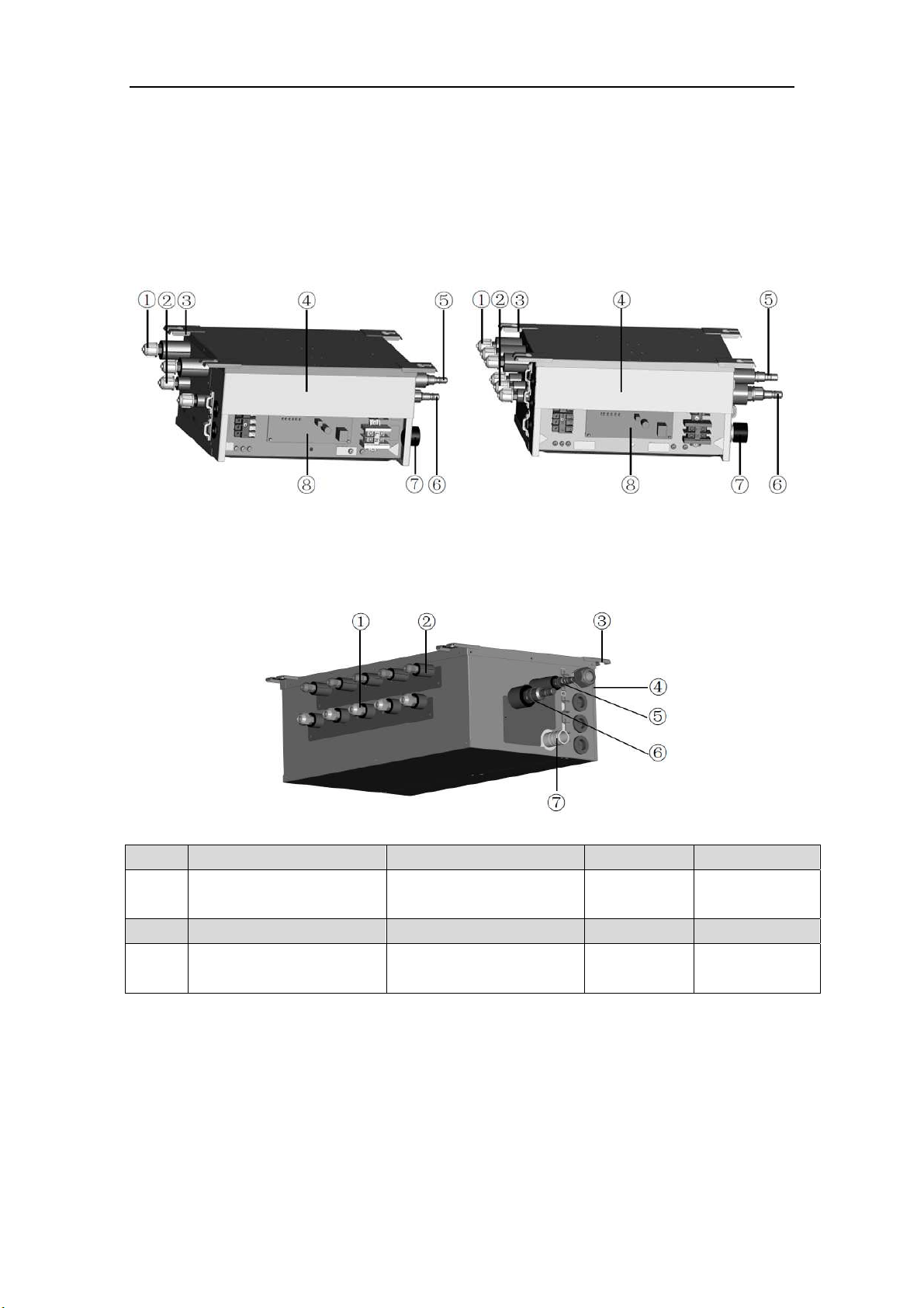
BU Module
3
2 Product Introduction
The BU module of Impecca Flex+ Series is the latest branch device, which adopts intelligent
control technology. Responding to the changes in load of the indoor units, it can coordinate the
flow rate of the refrigerant well. Otherwise, it is very compact and offers a flexible choice about
the installation location, such as the ceiling of parlor, corridor, balcony,storeroomand etc.
2.1 Names of Main Parts
a)IS-BU12
b)IS-BU13
e) IS-BU15
NO.
① ② ③ ④
Name
Gas piping of indoor unit
side
Liquid piping of indoor
unit side
Hanger metal
Electrical
equipment plate
NO.
⑤ ⑥ ⑦ ⑧
Name
Liquid piping of outdoor
unit side
Gas piping of outdoor unit
side
Drain hole
Printed circuit
board
Fig. 1
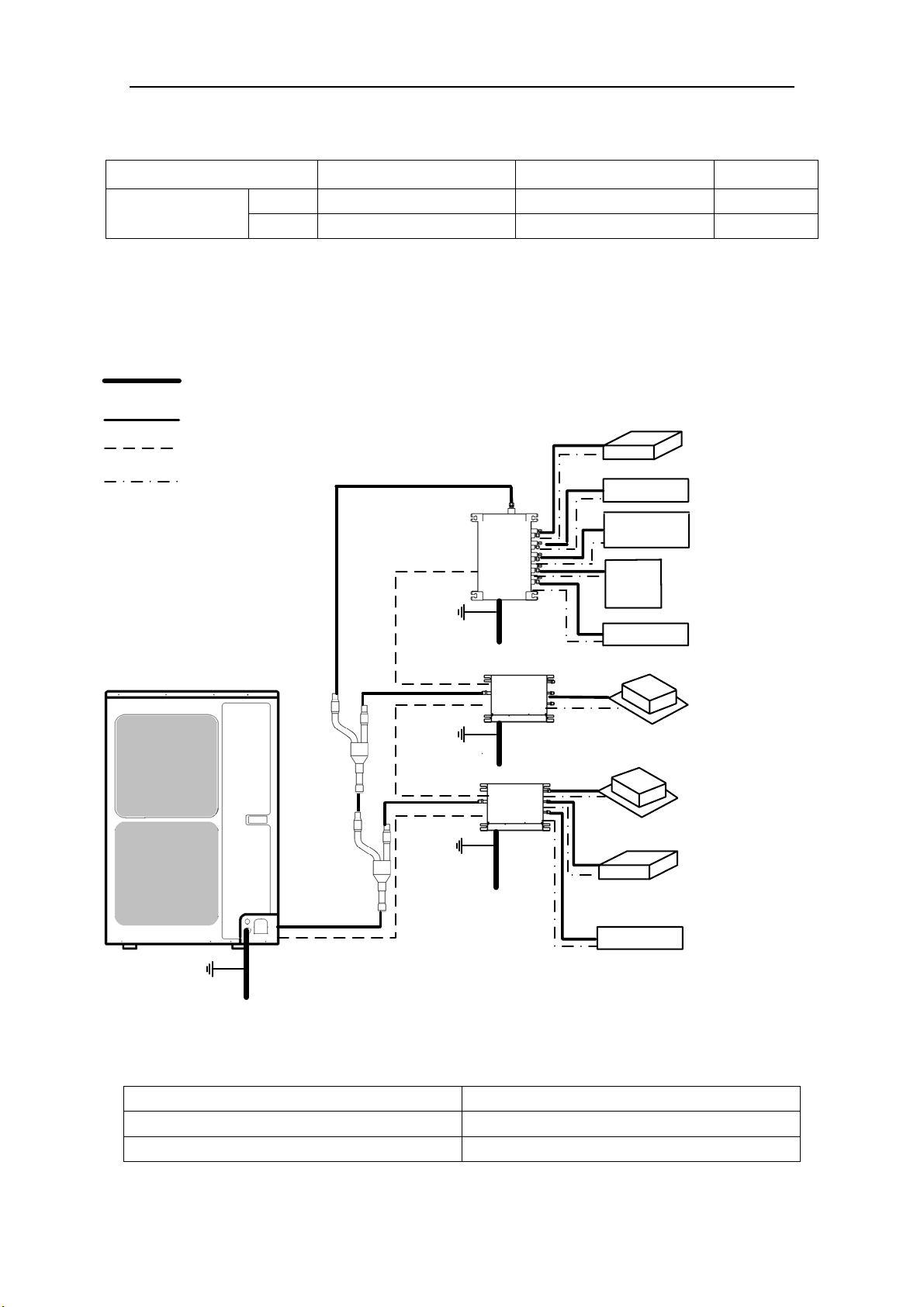
BU Module
4
2.2 Combinations for Outdoor and Indoor Units
Table 1
Sorts
IS-BU12
IS-BU13
IS-BU15
No. of connectable
indoor units
1 1 1 niM
5 3 2 xaM
2.3 Parts and Components of Unit
For the Super Free Match Series, one outdoor unit is able to drive up to three BU modules and
nine indoor units which include cassette type, duct type, wall-mounted type, floor ceiling type and
console type. The outdoor unit will run as long as any one indoor unit receives the running command,
and all indoor units stop once the outdoor unit is turned off.
Fig. 2
2.4 Working Temperature Range
Table 2
(BD :erutarepmet edistuO stroS ℃/℉)
05 mumixaM ℃(122℉)
51- muminiM ℃(5℉)
Outdoor unit
Power supply wire for outdoor
unit and BU module(3 wires)
Connection pipe
Transmission line(2 wires)
Power supply wire for
indoor unit(4 wires)
Ground
Power
(60Hz, 208/230V)
Power
(60Hz, 208/230V)
Power
(60Hz, 208/230V)
Power
(60Hz, 208/230V)
Ground
Ground
The 1st
branch
The 2nd
branch
BU 1
BU 2
BU 3
Indoor unit
Duct type
Duct type
Wall mounted
type
Wall mounted
type
Wall mounted
type
Cassette type
Cassette type
Floor ceiling
type
Console type
Ground
BU Module
5
3 Selection of Installation Location and Precautions
WAR N I N G
1) The installation of the air conditioner must be in accordance with the national and local laws and
regulations.
2) The quality of the installation will affect the capability of air conditioner directly. The installation
should be left to the appointed service center. Please contact your dealer after purchasing this machine.
Professional installation workers will provide installation and test services according to the installation
manual.
3) The air conditioner should not install in this place where the small animals exist, because they may
cause malfunctions, smoke or fire. Please keep the area around the unit clean.
3.1 Selection of Installation Location
WAR N I N G
1) The BU module must be installed on a firm and solid support which can withstand the weight of the
module and the mounting surface must be horizontal plane. The BU module can be chosen to install in
the ceiling, such as the ceiling of parlor, corridor, balcony, storeroom and etc.
2) The location must be out of children’s reach, please keep the unit away from children.
3) The BU module is for indoor use. If installing in the outdoors, the location must be away from wind and
rain. Otherwise, it maybe causes water leakage, electric shocks or fire etc.
4) There is enough space for the installation and maintenance.
5) Avoid direct sunlight or other heat sources exist.
6) Do not install in location that is hot or humid for long periods of time.
7) Avoid the BU module installed in the bedroom and study, where these places need to be quiet.
8) BU module cannot be installed in the place of inflammable and explosive materials and severe dust,
smoke and the other air pollution, such as the kitchen.
9) There is enough space to install drainage pipe, so that the condensed water can be discharged.
10) Installation at the following places might lead to the air conditioner malfunction, such as where is full of
machine oil, saline-sodic soil near the sea, sulphide fog, high frequency facilities or special conditions.
If it is unavoidable, please contact the appointed service center.
NOTICE
1) Make sure that the unit will not cause any operating vibration or noise after installation.
2) BU module shall be installed close to the indoor unit, hence to minimize the length and bends of
cooling pipe.
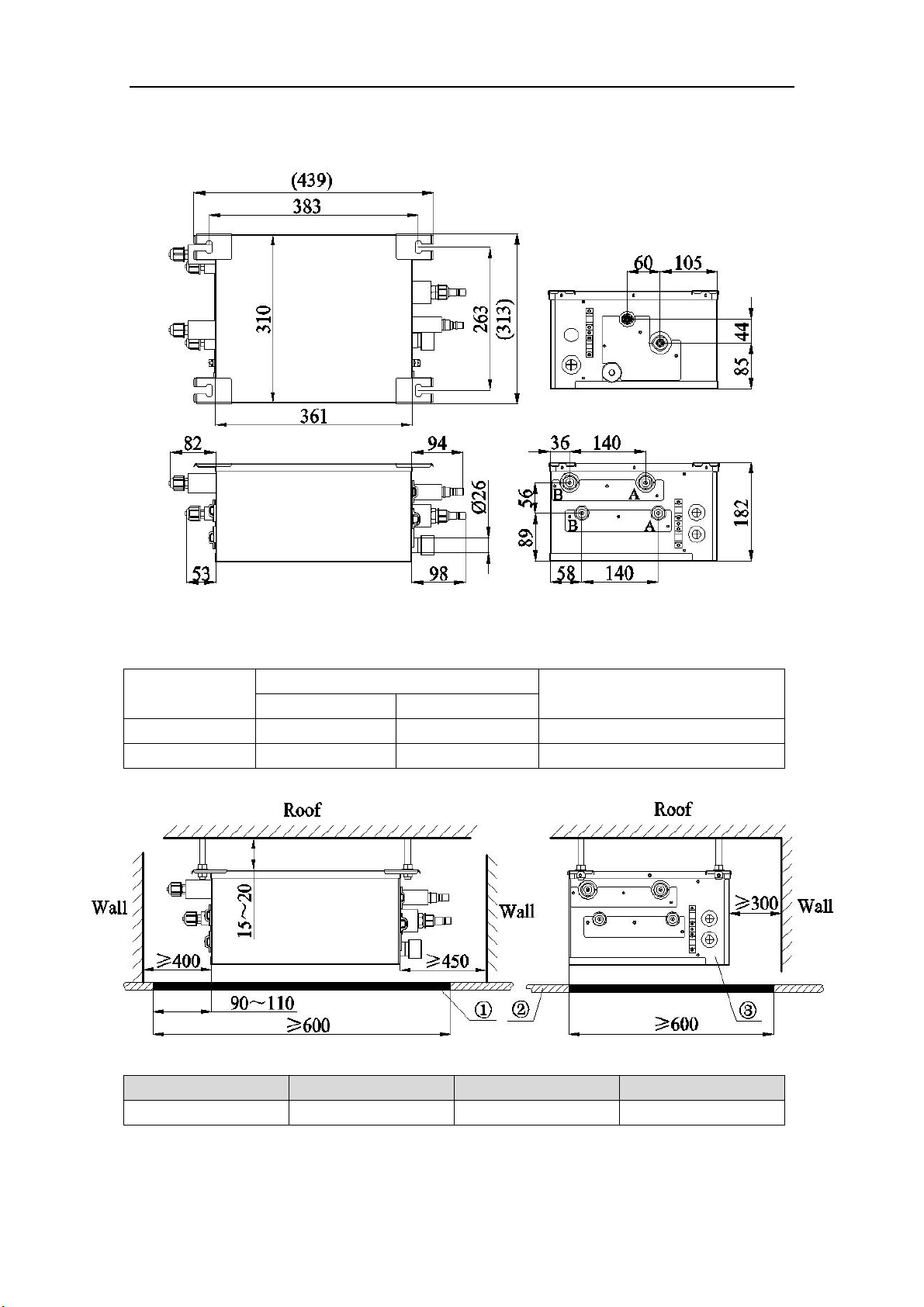
BU Module
6
3.2 Outline Dimension and Servicing Space of IS-BU12
1) Outline dimension
Fig. 3 (mm)
Table 3
Sorts
Indoor unit side (mm/inch)
Outdoor unit side (mm/inch)
Port A Port B
Liquid pipe Φ6.35(1/4) Φ6.35(1/4) Φ9.52(3/8)
Gas pipe Φ9.52(3/8) Φ9.52(3/8) Φ15.9(5/8)
2) Installation and service space
NO.
① ②
③
Name Servicing space Ceiling Electrical box side
Fig. 4 (mm)
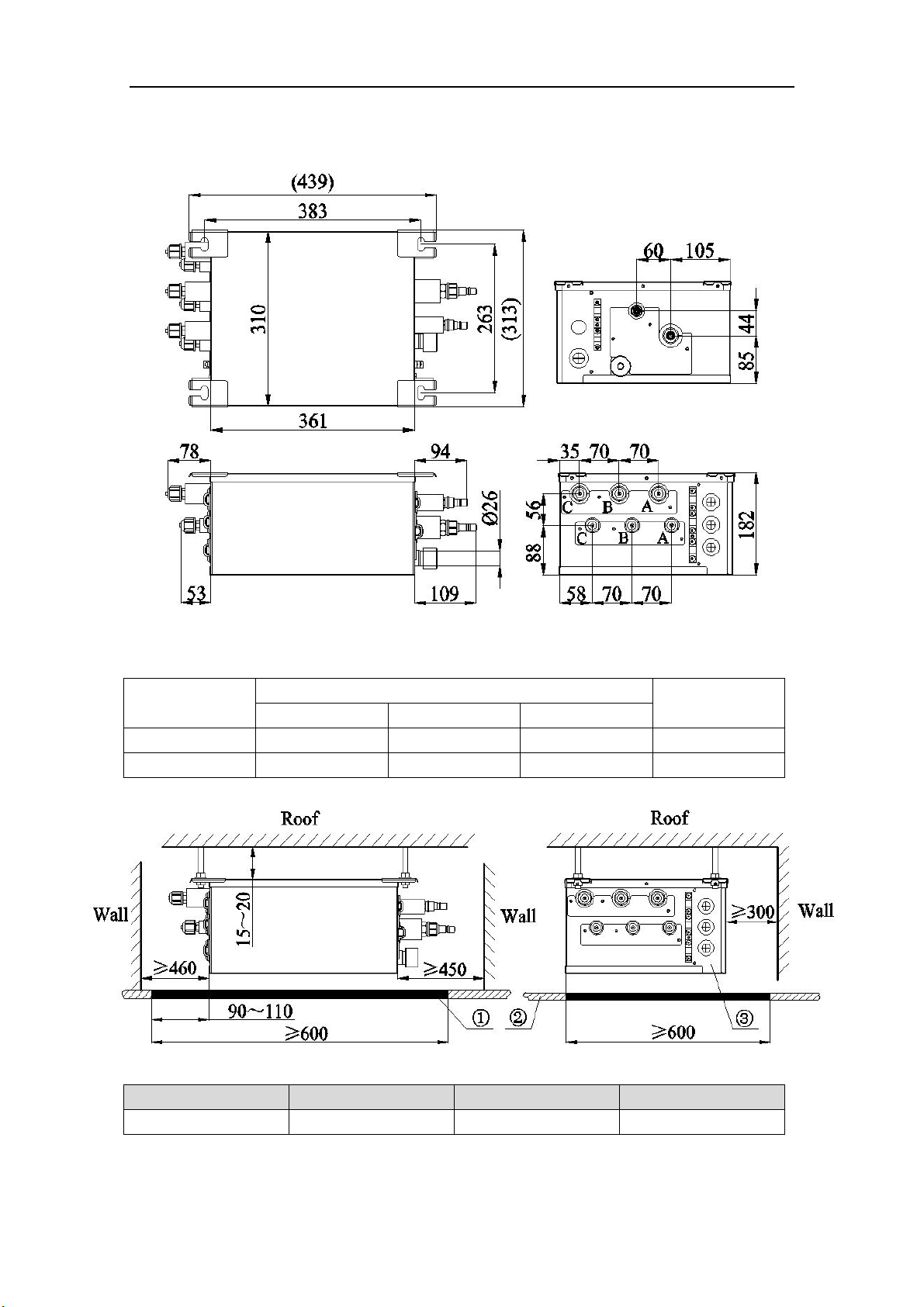
BU Module
7
3.3 Outline Dimension and Servicing Space of IS-BU13
1) Outline dimension
Fig. 5 (mm)
Table 4
Sorts
Indoor unit side (mm/inch)
Outdoor unit side
(mm/inch)
Port A Port B Port C
Liquid pipe Φ6.35(1/4) Φ6.35(1/4) Φ6.35(1/4) Φ9.52(3/8)
Gas liquid Φ9.52(3/8) Φ9.52(3/8) Φ9.52(3/8) Φ15.9(5/8)
2) Installation and service space
NO.
① ②
③
Name Servicing space Ceiling Electrical box side
Fig. 6 (mm)
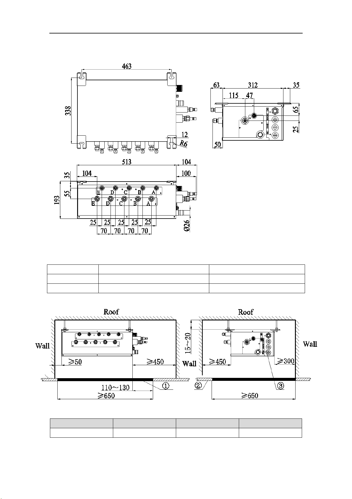
BU Module
10
3.6 Outline Dimension and Servicing Space of IS-BU15
1) Outline dimension
Fig. 11
(mm)
Table 7
Sorts Indoor unit side (mm/inch) Outdoor unit side (mm/inch)
Liquid pipe Φ6.35(1/4) Φ9.52(3/8)
Gas pipe Φ9.52(3/8) Φ15.9(5/8)
2) Installation and service space
NO.
① ②
③
Name Servicing space Ceiling Electrical box side
Fig. 12 (mm)
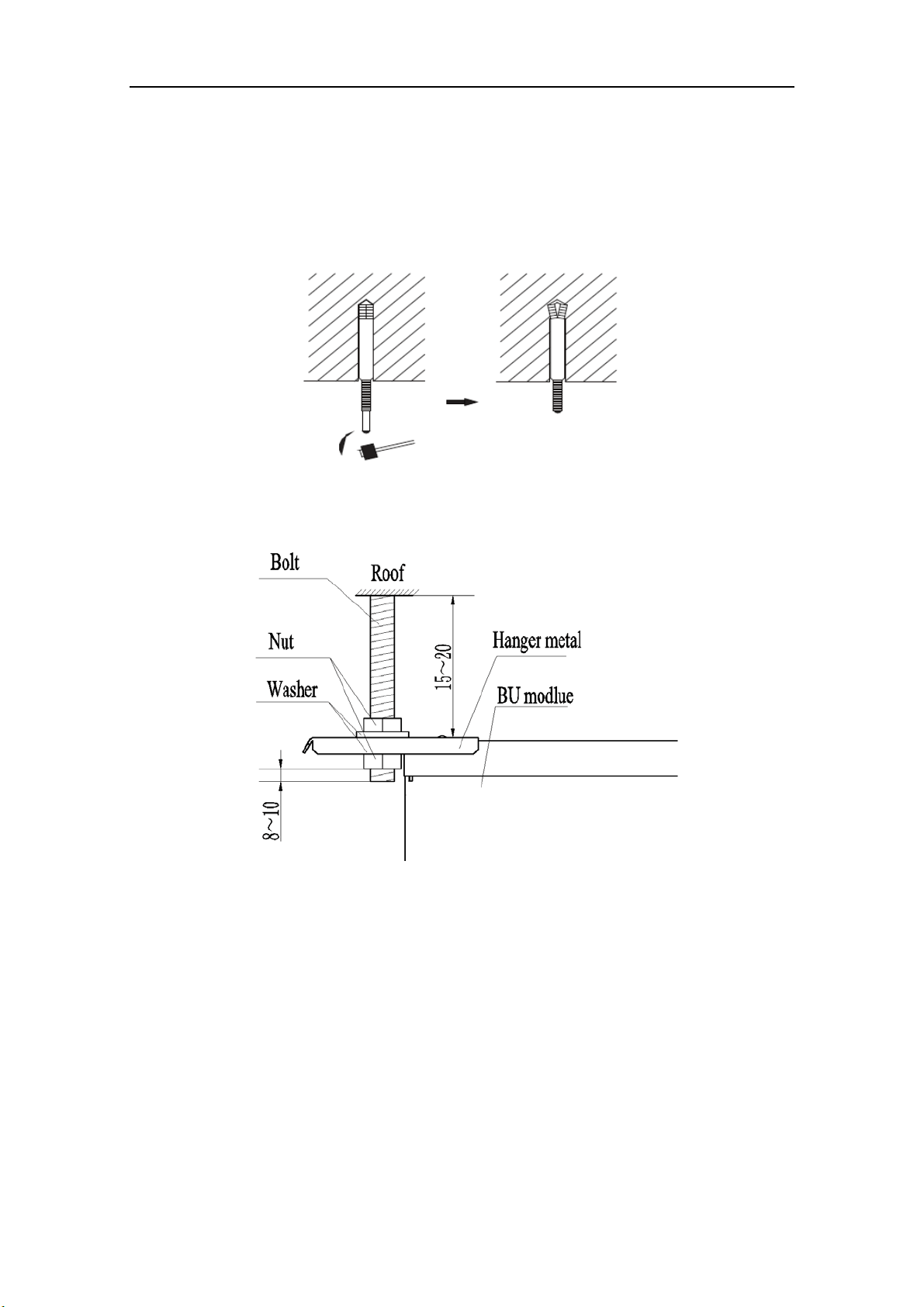
BU Module
11
4 Installation Instruction
1) Check the installation location and ensure it is strength and level. Otherwise, there should be
enough space to install drainage pipe, so that the condensed water can be discharged.
2) Reference to the size of hanger metal and drill 4 holes in the installation location.
3) Hang the hanger bolts.
Fig. 13
4) Fix the modules securely with the hanger bolts. You can get the M10 or M8 hanger bolts, nuts
and washers from the market.
Fig. 14 (mm)
5) Adjusting the nuts position, so that the BU module should be level in front/back and left/right.

BU Module
12
5 Installation of Refrigerant Pipes
5.1 Allowable Length and Drop Height of Connecting Pipe
Fig. 15 (8 indoor units)
Table 8
The sorts The pipes Length(m/feet)
Maximum
allowable
length
Total length between outdoor unit and BU
modules
L1+L2+L3+L4+L5 ≤55(181)
Total length
between indoor
units and BU
1A+1B+1C+2A+2B+2C+
3A+3B
ISMO-6021 ≤90(295)
Between indoor unit and BU module 1A;1B;1C;2A;2B;2C;3A;3B ≤15(49)
Between indoor unit and the 1st branch
L4+1B;L2+L5+2A;
L2+L3+3B
≤40(131)
Maximum
allowable
length
Between outdoor and indoor units H1 ≤30(99)
Between outdoor units and BU modules H2 ≤30(99)
Between BU and BU modules H3 ≤15(49)
Between indoor and indoor units H4 ≤15(49)
Minimum
allowable
length
Between outdoor and the 1st branch L1 ≥5(16)
Between BU and the branch L3;L4;L5
as possible as
short
NOTICE! BU module should be placed within the level between the outdoor unit and indoor
unit.
5.2 Installation of Piping Adapter (IS-BU12 IS-BU13 and IS-BU15)
If the piping connection size of BU module does not match with that of the outdoor unit and
indoor units, it should prevail with the piping connection size of the outdoor unit and indoor units.
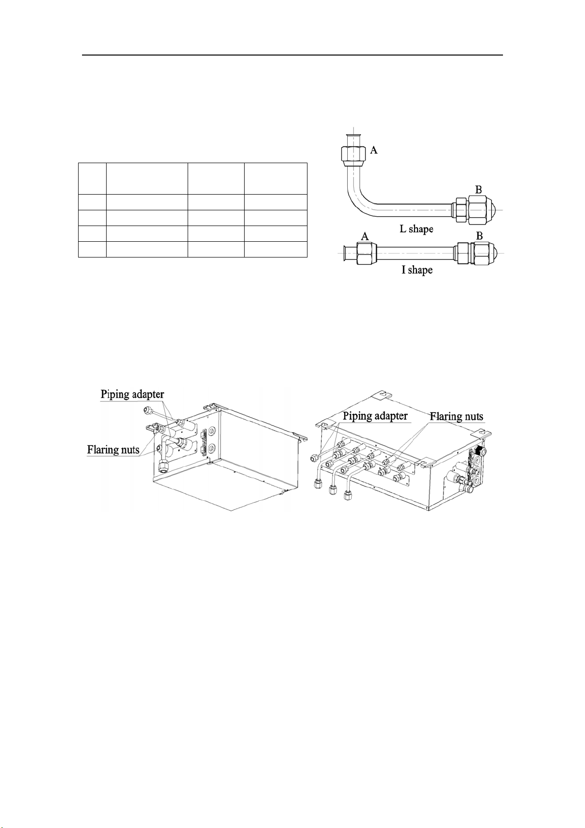
BU Module
13
Install the optional piping adapters to the BU module, so that the piping connection size of BU
module can match with that of the outdoor unit and indoor units.
1) Piping adapter(Optional accessories)
Table 9
NO. Name
Port A
(mm/inch)
Port B
(mm/inch)
1 Φ15.9→Φ19.05 Φ15.9(5/8) Φ19.05(3/4)
2 Φ9.52→Φ12.7 Φ9.52(3/8) Φ12.7(1/2)
3 Φ9.52→Φ15.9 Φ9.52(3/8) Φ15.9(5/8)
4 Φ6.35→Φ9.52 Φ6.35(1/4) Φ9.52(3/4)
Fig. 16
2) Install the piping adapter
① Refer to the piping connection size of the outdoor unit and indoor units, the appropriate piping
adapter should be adopted.
② Align the flared end of copper tube with the center of pipe joint. Tighten the nuts with hands.
Then tighten the flaring nuts with torque wrench until you hear a “click”.
Fig. 17
3) Sealing the unconnected port
If the port of BU module indoor side does not connected to one indoor unit, the port must be
sealed to prevent refrigerant leaks. Please tighten the copper flaring nuts to the unconnected port
with torque wrench until you hear a “click”.
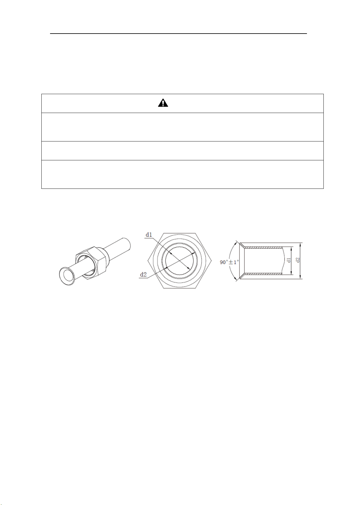
BU Module
15
5.4 Precaution for Connection
CAUTION
1) Conform to the following principles during pipe connection: Outdoor unit shall be installed close to the
indoor unit, hence to minimize the length and bends of connection pipes; the height gap of outdoor unit
and indoor units should be as small as possible; the radius of curvature should be as large as possible.
2) The brazing operation must be strictly in accordance with the process requirements. Rosin joint or pin
hole is not allowed.
3) During the installation, do not damage the pipeline. The pipeline’s radius of bending must be over than
200mm (8inch). The pipes cannot repeatedly be bent or straightened. Otherwise it will get harden and
crack. Do not bend or straight the pipes for more than 3 times at the same position.
1) The process of flaring
① Using the tube cutter to cut the connecting pipe in the appropriate place and remove the burrs.
② Install the nut before the flaring operation.
③ Check the flared portion, whether there is fractured or not.
Fig. 21
2) Precaution for elbow operation
① The elbow operation could be done by hands. Be careful and do not damage the pipe.
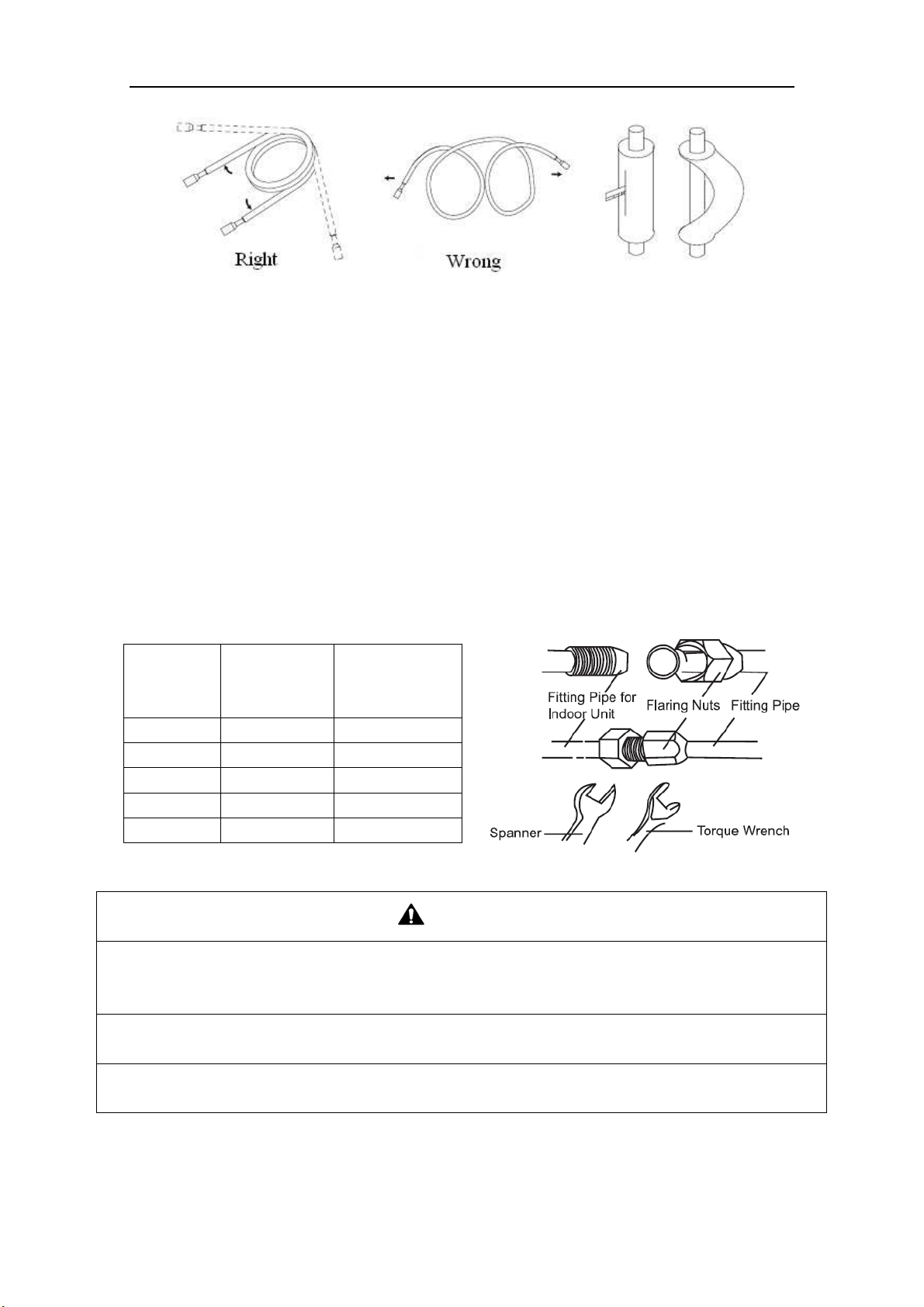
BU Module
16
Fig. 22
② If the thermal insulation of the refrigerant pipe is not removed, please do not bend the pipe.
Otherwise, it maybe leads the pipe to crack. It is better to make an incision with a knife in the
thermal insulation and removes it. After elbow operation is finished, recover the thermal
insulation with binding band.
3) The process of install refrigerant pipes
① Remove the screw caps from the pipes.
② Align the flared end of copper tube with the center of pipe joint. Tighten the nuts by hands. (If
the flared end of copper tube and the center of pipe joint are not in coaxial, it is hard to tighten
the nuts by hands, please do not tighten it with spanners, because the screw thread may be
broken by force).
③ Tighten the flaring nuts with torque wrench until you hear a “click”. (The spanner and torque
wrench should be perpendicular to the refrigerant pipeline).
④ The following table for the torque required to tighten the nuts.
Table 10
Pipe
diameter
(mm/inch)
Thickness of
copper
tube(mm/inch)
Tightening
torque
(N·m/1bf·ft)
Φ6.35(1/4) ≥0.8(1/32) 15~30(11~22)
Φ9.52(3/8) ≥0.8(1/32) 35~40(26~29)
Φ12.7(1/2) ≥0.8(1/32) 45~50(33~37)
Φ15.9(5/8) ≥1.0(1/25) 60~65(44~48)
Φ19.05(3/4) ≥1.0(1/25) 70~75(52~55)
Fig. 23
CAUTION
1) During the connection of the indoor unit and BU module to the refrigerant pipe, never pull any joints of
the indoor unit and the BU module by force; otherwise the capillary pipe or other pipe may crack,
which then would result in leakage.
2) The refrigerant pipe should be supported by brackets; that is, don’t let the unit support its weight.
3) For the Flex+ system, each pipe should be labeled to tell which system it belongs to avoid
mistaken, inaccurate piping.

BU Module
17
6 Electrical Wiring Work
6.1 Wiring Connection
NOTICE! The “L1”, “3” terminals are connected to the live wire, the “L2”,”N(1)” terminals
are connected to the neutral wire and the ”2” terminal is connected to the transmission line.
Fig. 24
6.2 Requirements of Power Circuit and Cable
Table 11
Phase and frequency 1Ph,60Hz
Voltage 208/230V
Recommended cable of outdoor unit
(Pieces × Sectional area)
3×6.0 mm
2
ISMO-6021
Recommended cable of BU module (Pieces × Sectional area) 3×0.75 mm
2
Transmission line (Pieces × Sectional area) 2×1.5 mm
2
Recommended cable of indoor unit (Pieces × Sectional area) 4×0.75mm
2
Capacity of the air switch
ISMO-6021 40A
BU module 10A
NOTICE
1) The total length of the transmission line between the outdoor unit and the furthest BU module is not
more than 180 feet (55m). Otherwise, the system cannot work possibility.
2) The specifications of the power cable and transmission line listed in the table above are determined
based on the maximum power (maximum amps) of the unit.
3) The specifications of the power cable listed in the table above are applied to the conduit-guarded
BU Module
18
multi-wire copper cable (like, YJV copper cable, consisting of PE insulated wires and a PVC cable
jacket) used at 104℉ (40℃) and resistible to 194℉ (90℃), and shall be at least those of ordinary
polychloroprene sheathed cords. If the working condition changes, they should be modified according
to the related national standard.
4) The specifications of the air switch listed in the table above are applied to the breaker with the working
temperature 104℉ (40℃). If the working condition changes, they should be modified according to the
related national standard.
5) The length of the recommended power cable should be less than 49 feet (15 meters); otherwise,
the diameter of the power cable is not enough.
6) Written power cable and transmission line length is just a reference value. It may be different
depending on the condition of installation, humidity or materials, etc.
7) An all-pole disconnection switch having a contact separation of at least 3mm (1/8 inch) in all poles
should be connected in fixed wiring.
6.3 Ground Requirements
WAR N I N G
1) The air conditioner is classified into the Class I appliances, so its ground ways must be reliable.
2) The ground wire must be fixed on the screw hole with the sign as the right figure.
3) The yellow-green wire of the air conditioner is the ground wire and must be fixed by the tapping screw.
And it cannot be used for other purpose or cut off. Otherwise, it will cause the hazard of electric shock.
4) The reliable ground terminal should be provided and the ground wire cannot be connected to any of the
following places: a. Water pipe; b. Coal gas pipe; c. Sewage pipe; d. Lightning rod
e. Telephone line f. Other unreliable places considered by a professional.
6.4 Precautions on the Electrical Wiring Work
WAR N I N G
1) The electrical installation should be carried out by the professional as instructed by the local laws,
regulations and also this manual.
2) The ground connection should be reliable and the ground wire should be connected to the dedicated
device of the building by the professional.
3) Before starting work, the power must not be supplied to the unit.
4) The air switch coupled with the leakage current protection switch must be equipped in the circuits,
which is of enough capacity and of both magnetic and thermal tripping functions in case of the short
circuit and overload.
5) The electrical work should use a cable length enough to cover the entire distance with no connection. If
it is unavoidable, please make sure the connection should be reliable, the external forces will not act on
the wires and the joint is not bared. Otherwise it will cause electrical shock or fire etc.
6) The power cable with the rated voltage and exclusive circuit for the air conditioner should be used.
7) Do not pull the power cable by force after it is installed.
8) The diameter of the power cable should be large enough and once it is damaged, it must be replaced by
the dedicated one.
9) The multi-wire copper cable should be used for the power cable and the transmission line.
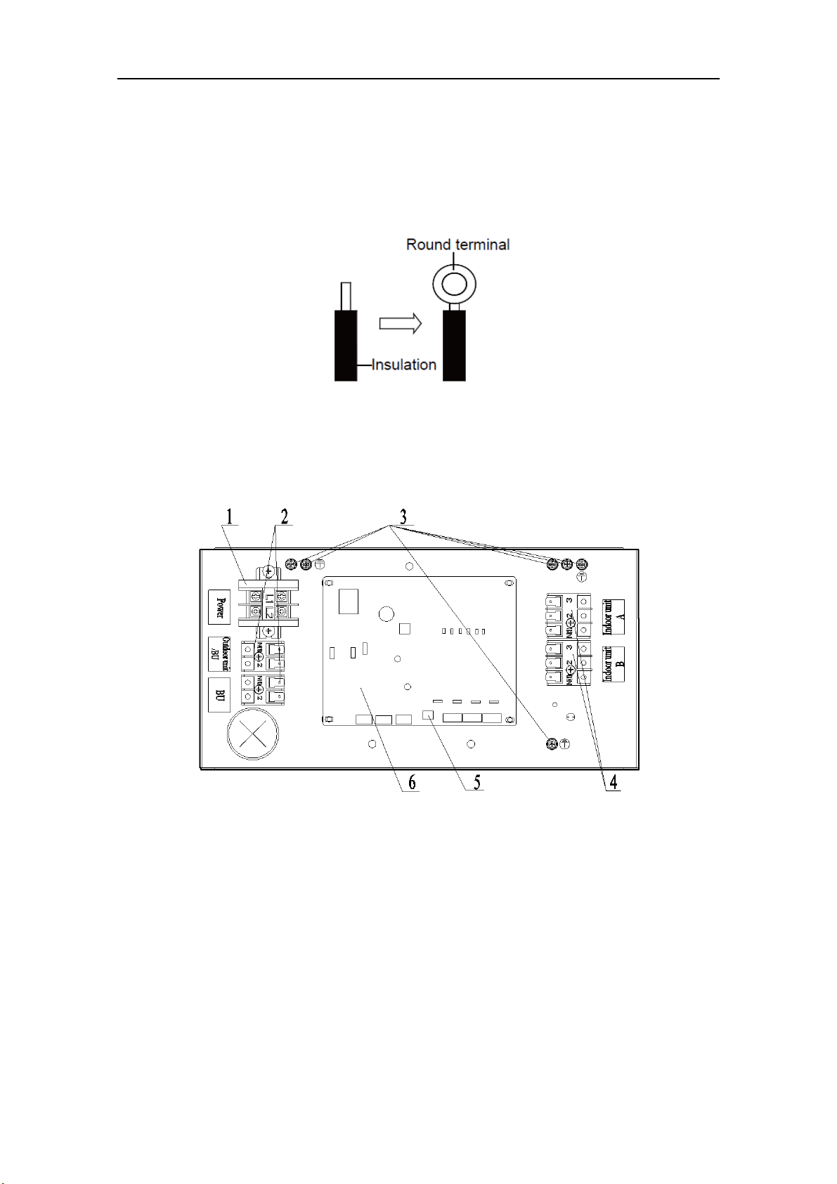
BU Module
19
6.5 Precaution of Laying Wires
1) Use a wire stripper to strip off a length of the insulation layer at the end of the wires;
2) Loosen the screws on the terminal block of the air conditioner;
3) Press the ends of the cable tightly onto the round terminals corresponding to the size of the
screws.
4) Pass the screw through the round terminals and fix it onto the terminal block.
Fig. 25
6.6 Procedures for Electrical Wiring Work
1) Unscrew the electrical equipment plate.
2) The structure of behind the electrical equipment plate.
a) IS-BU12
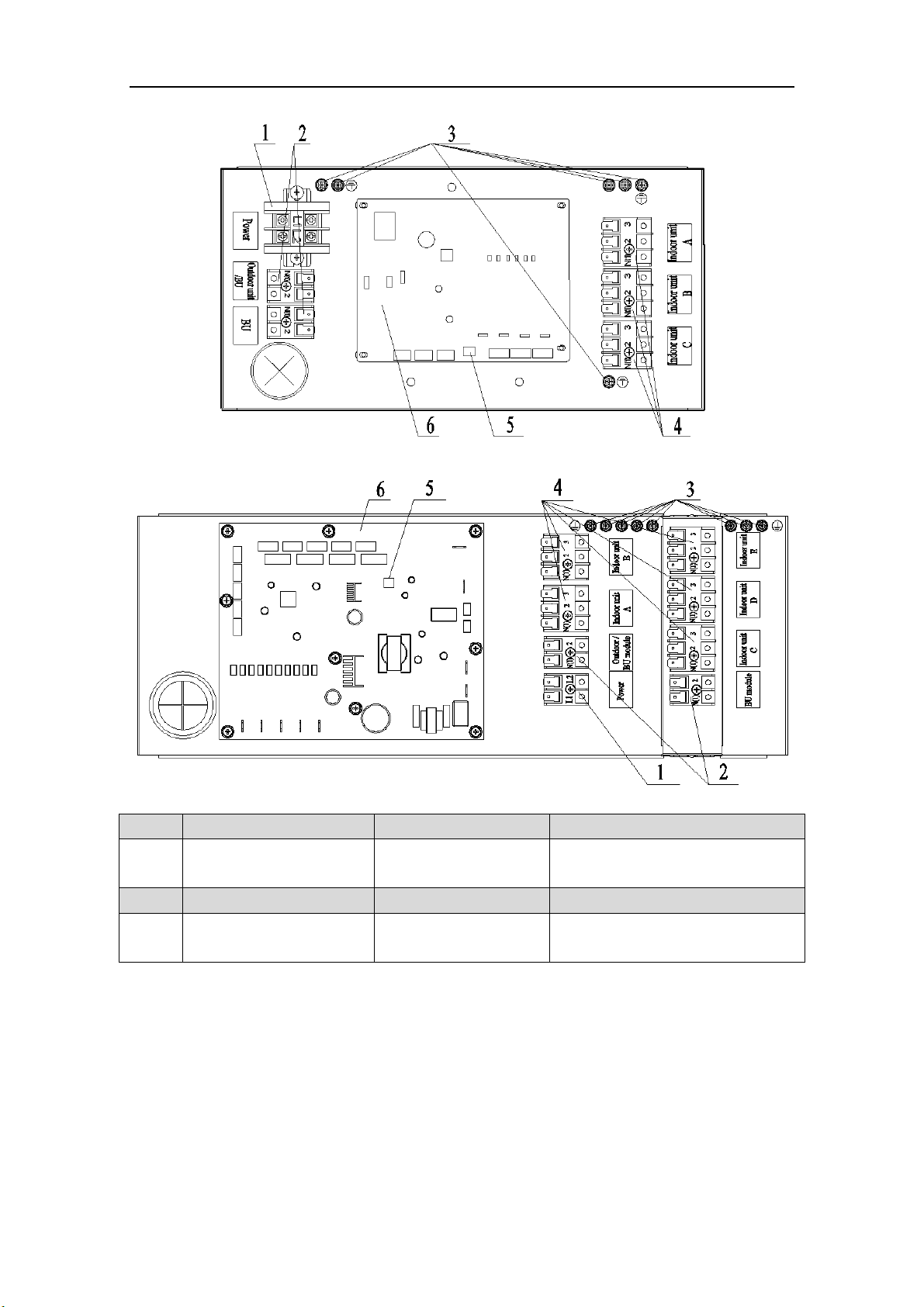
BU Module
20
b
) IS-BU13
c) IS-BU15
NO. 1 2 3
Name
Terminal black for BU
module power supply
Terminal black for
transmission line
Ground screw
NO. 4 5 6
Name
Terminal black for indoor
unit power supply
DIP switch Printed circuit board
Fig. 26
3) Let the power cable and transmission line go through the rubber ring. In order to protect the
power cable and transmission line from damaging by the hole, the rubber ring cannot fall from
that, otherwise, it may cause electrical shock or fire etc.
4) Connect the power cable of the BU module to the L1, L2 terminals with the sign of Power and
as well as the ground screw.
5) Connect the transmission line of the BU module to the N(1), 2 terminals with the sign of
Outdoor unit/BU module.
6) If the transmission line need to be connected to the other BU module, please connect the extra
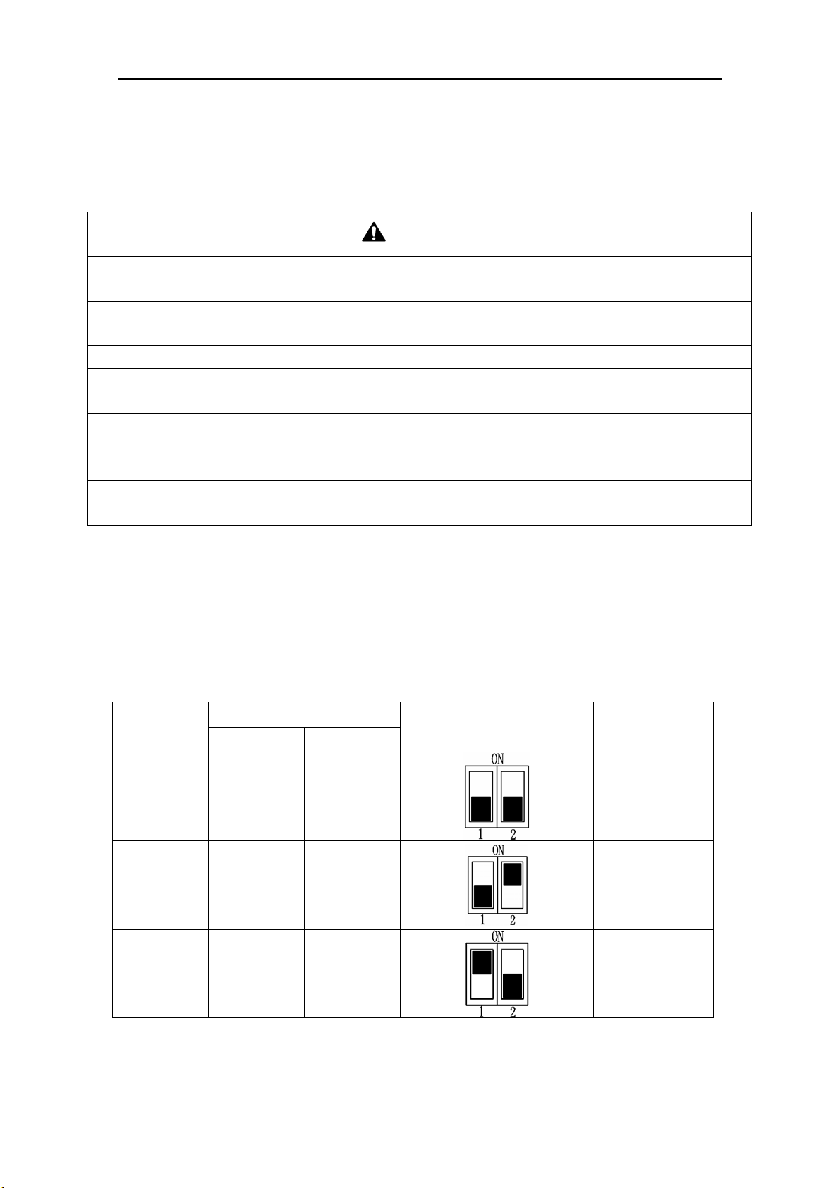
BU Module
21
line to the N(1), 2 terminals with the sign of BU module.
7) Connect the power cable of the indoor unit to the N(1), 2 and 3 terminals with the sign of
Indoor unit A (B, C, D and E) and as well as the ground screw.
8) Fix the power cable and transmission line firmly by cable fixing clip.
9) Screw the electrical equipment plate.
CAUTION
1) The transmission line and the power cable must be separated with an interval of at least 2cm (3/4inch);
otherwise it may be result in communication problem.
2) Confirm the each cable connected to the terminal screw is exactly and securely after finishing the
electric work.
3) Fix each ground wire separately with the ground screw.
4) When connecting indoor units, make sure to connect refrigerant pipes and power cables to the same
connection ports marked with matching signs (A, B, C ,D and E).
5) If the connecting wire is connected to the terminal incorrectly, the unit will not work normally.
6) The refrigerant pipe should be supported by brackets, that is, don’t let the unit withstand the weight of
it.
7) For the Flex+ system, each pipe should be labeled to tell which system it belongs to avoid
mistaken inaccurate piping.
6.7 Instructions for DIP Switch
2 digits DIP is adopted to assign the address when using multi-BU modules and the address
cannot be repeated in the same unit.
One outdoor unit can connect to no more than 3 BU modules.
“ON” side means "ON" and the opposite side represents "OFF".
NOTICE!: The black part is lever.
Table 12
Number
DIP Code
Icon Address
DIP 1 DIP 2
1 OFF OFF BU 1
2 OFF ON
BU 2
3 ON OFF BU 3

BU Module
22
7 Design of Drainage Pipeline
7.1 Installation of Drain Hose
1) Remove the rubber stopper of drain hole.
2) Connect the drain hose to the drain hole of BU module.
3) The drain hose should be kept at 5-10 degrees of gradient to facilitate discharge of the
condensing water. Take care that does not exert too much force on the hose.
4) Thermal insulation materials should be placed at the joints of the drain hose so as to prevent
from dew condensation. Fix the drain hose firmly by binding band.
Fig. 27
5) The end of the drain hose should be inserted into the hole of drainage pipeline.
7.2 Design of Drainage Pipeline
1) The drainage pipeline should be kept at a certain gradient (1/50-1/100) so as to avoid bulges of
pipes where there might be water bends.
2) The drainage pipeline is form of the hard PVC pipes for common purposes which can be
purchased locally. The diameter of the PVC pipes is not less than 31mm (1-1/4inch) and the
pipeline should be fixed as close to the BU module as possible.
3) Insert the drain hose into the drain hole of drainage pipeline. Use binding band to fix it tightly.
It is not allowed to use adhesive glue to join the drain hose to the drainage hole.
4) When the drainage pipeline is laid for a couple of units, the position of the shared pipeline
should be approximately 100mm lower than the drainage hole of each module. In this case,
some special-purpose pipes with thicker walls will be used.
NOTICE! At intervals of about 1 meter (3-1/4feet), fix the drain pipes to the wall with
brackets, not floating in the air.
8 Test Operation
After all the installation has been accomplished, follow the “operation test” as described in the
outdoor unit owner’s manual.
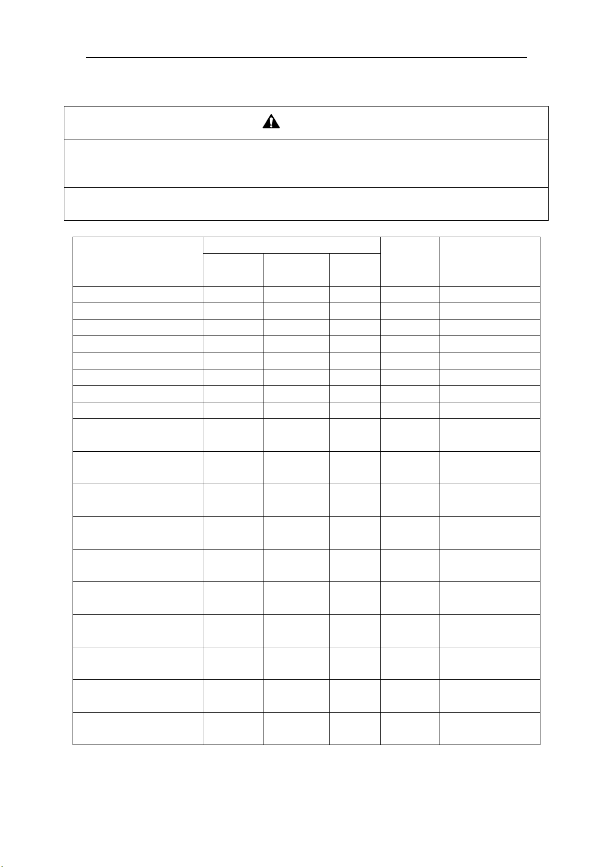
BU Module
23
9 Troubleshooting
WAR N I N G
1) In the event of abnormal conditions (such as an unpleasant smell), please shut off the power supply
immediately and then contact the appointed service center; otherwise, the abnormal running would
damage the air conditioner and also would cause electric shock or fire hazard .
2) Do not repair the air conditioning personally but instead contact the professionally skilled personnel at
the appointed service center, as the incorrect repair would cause electric shock or fire hazard etc.
Table 13
Errors
Indicating LED flashing times
Indoor
unit error
code
Outdoor unit error
code
Yellow
LED
Green
LED
Red
LED
BU 1 is connected
Flash 1 time
BU 2 is connected
Flash 2 times
BU 3 is connected
Flash 3 times
Indoor unit A is connected
Flash 1 time
Indoor unit B is connected
Flash 2 times
Indoor unit C is connected
Flash 3 times
Indoor unit D is connected
Flash 4 times
Indoor unit E is connected
Flash 5 times
Indoor unit A gas tube
temperature sensor error
Flash 1
time
b7
b7 indoor unit
address
Indoor unit A liquid tube
temperature sensor error
Flash 2
times
b5
b5 indoor unit
address
Indoor unit B gas tube
temperature sensor error
Flash 3
times
b7
b7 indoor unit
address
Indoor unit B liquid tube
temperature sensor error
Flash 4
times
b5
b5 indoor unit
address
Indoor unit C gas tube
temperature sensor error
Flash 5
times
b7
b7 indoor unit
address
Indoor unit C liquid tube
temperature sensor error
Flash 6
times
b5
b5 indoor unit
address
Indoor unit D gas tube
temperature sensor error
Flash 7
time
b7
b7 indoor unit
address
Indoor unit D liquid tube
temperature sensor error
Flash 8
times
b5
b5 indoor unit
address
Indoor unit E gas tube
temperature sensor error
Flash 9
time
b7
b7 indoor unit
address
Indoor unit E liquid tube
temperature sensor error
Flash 10
times
b5
b5 indoor unit
address
10 After-Sales Service
If there is any quality or other issue, please contact the after-sales service center.

CUSTOMER SUPPORT
Before contacting customer support, please see the troubleshooting guide above.
Visit our website to contact us, find answers to Frequently Asked Questions, and for other
resources which may include an updated version of this user's guide.
WWW.IMPECCA.COM
If you wish to contact us by phone, please be sure to have your model number and serial
number ready and call us between 9:00am and 6:00pm ET, at +1 866-954-4440.
Keep tabs on Impecca's newest innovations & enter contests via our social network feeds:
www.facebook.com/Impecca/
www.instagram.com/impecca/
@impeccausa
© 2016 Impecca, a division of LT Inc., Wilkes Barre, PA.

Split Air Conditioner
Thank you for choosing our product.
For proper operation, please read and keep this manual carefully.
If you have lost the Owner’s Manual, please contact the local agent or visit
www.impecca.com for an electronic version.
Models:
ISMI-W092
ISMI-W122
v. 1.1

R410A(R32/125: 50/50): 1975
Operation Notices
Precautions............................................................................................................1
Parts name ............................................................................................................6
Screen Operation Guide
Buttons on remote controller .................................................................................7
Introduction for icons on display screen ................................................................7
Introduction for buttons on remote controller .........................................................8
Function introduction for combination buttons.....................................................12
Operation guide...................................................................................................13
Replacement of batteries in remote controller.....................................................13
Emergency operation .......................................................................................... 14
Maintenance
Clean and maintenance....................................................................................... 14
Malfunction
Malfunction analysis ............................................................................................17
Installation Notice
Installation dimension diagram............................................................................21
Tools for installation .............................................................................................22
Selection of installation location ..........................................................................22
Requirements for electric connection ..................................................................23
Installation
Installation of indoor unit......................................................................................24
.29
Check after installation
...........................
.
............................................................
29
Test and operation
Test operation
......................................... ............................................................
Attachment
.........................................................................30
Pipe expanding method
Configuration of connection pipe
.......................................................................................32
Content
Wired Controller...................................................................................................
33
This appliance is not intended for use by persons (including children) with reduced physical, sensory
or mental capabilities, or lack of experience and knowledge, unless they have been given supervision
or instruction concerning use of the appliance by a person responsible for their safety.
Children should be supervised to ensure that they do not play with the appliance.

Explanation of Symbols
Indicates a hazardous situation that, if not avoided, will
result in death or serious injury.
Indicates a hazardous situation that, if not avoided, could
result in death or serious injury.
Indicates a hazardous situation that, if not avoided, may
result in minor or moderate injury.
Indicates important but not hazard-related information,
used to indicate risk of property damage.
Indicates a hazard that would be assigned a signal word
WARNING or CAUTION.

Precautions
WARNING
Do not connect air conditioner to multi-purpose socket.
This appliance can be used by children aged from 8
Operation and Maintenance
If the supply cord is damaged, it must be replaced by
the manufacturer, its service agent or similarly qualified
persons in order to avoid a hazard.
Do not spray water on indoor unit. It may cause electric
shock or malfunction.
Otherwise, it may cause fire hazard.
Children shall not play with the appliance.
Cleaning and user maintenance shall not be made by
children without supervision.
years and above and persons with reduced physical,
sensory or mental capabilities or lack of experience
and knowledge if they have been given supervision or
instruction concerning use of the appliance in a safe
way and understand the hazards involved.
Do not wash the air conditioner with water to avoid
electric shock.
After removing the filter, do not touch fins to avoid injury.
Do not use fire or hair dryer to dry the filter to avoid
deformation or fire hazard.
Do disconnect power supply when cleaning air
conditioner. Otherwise, it may cause electric shock.
.
1
Do not block air outlet or air inlet. It may cause
malfunction.
remote controller may be broken.
Ɣ Power cord is overheating or damaged.
Ɣ There’s abnormal sound during operation.
Ɣ Circuit break trips off frequently.
Ɣ Air conditioner gives off burning smell.
Ɣ Indoor unit is leaking.
contact the dealer or qualified professionals for service.
When turning on or turning off the unit by emergency
operation switch, please press this switch with an insulating
object other than metal.
outlet. It may cause personal injury or damage.
Precautions
WARNING
conditioner and disconnect power immediately, and then
If the air conditioner operates under abnormal conditions,
it may cause malfunction, electric shock or fire hazard.
Do not spill water on the remote controller, otherwise the
electric shock or damage. Please contact dealer when
you need to repair air conditioner.
Do not repair air conditioner by yourself. It may cause
objects. It may cause damage or personal injury.
Do not step on top panel of outdoor unit, or put heavy
When below phenomenon occurs, please turn off air
Do not extend fingers or objects into air inlet or air
Maintenance must be performed by qualified
professionals. Otherwise, it may cause personal injury
or damage.
2

Do install the circuit break. If not, it may cause malfunction.
of at least 3mm in all poles should be connected in fixed
wiring.
magnet buckle
and heating buckle function, it can protect
the circuit-short and
overload.
power supply circuit and circuit break.
Precautions
WARNING
note
the following table.Air switch should be included
Make sure the power supply matches with the
requirement of air conditioner.Unstable power supply or
incorrect wiring or malfunction. Please install proper power
supply cables before using the air conditioner.
An all-pole disconnection switch having a contact separation
Must follow the electric safety regulations when installing
the unit.
grounding wire of power socket.
Properly connect the live wire, neutral wire and
any work related to electricity and safety.
Be sure to cut off the power supply before proceeding
Including an circuit break with suitable capacity, please
Air Conditioner should be properly grounded. Incorrect
Don't use unqualified power cord.
grounding may cause electric shock.
According to the local safety regulations, use qualified
Installation must be performed by qualified professionals.
Otherwise, it may cause personal injury or damage.
Attachment
3

Installation must be performed in accordance with the
persons in order to avoid a hazard.
must be properly grounding with specialized grounding
device by a professional. Please make sure it is always
grounded effectively, otherwise it may cause electric shock.
The appliance must be positioned so that the plug is
accessible.
If the length of power connection wire is insufficient, please
contact the supplier for a new one. Avoid extending the
wire by yourself.
All wires of indoor unit and outdoor unit should be
connected by a professional.
national wiring regulations.
requirement of NEC and CEC by authorized personnel
only.
Precautions
WARNING
wire, which can't be used for other purposes.
The grounding resistance should comply with national
electric safety regulations.
The air conditioner is the first class electric appliance. It
keep the interconnection cable away from the copper
tube.
The temperature of refrigerant circuit will be high, please
the manufacturer, its service agent or similarly qualified
If the supply cord is damaged, it must be replaced by
The yellow-green wire in air conditioner is grounding
The appliance shall be installed in accordance with
Do not put through the power before finishing installation.
4
The indoor unit should be installed close to the wall.
reachable after finishing installation.
far away from animals or plants.If it is unavoidable,
please add the fence for safety purpose.
Precautions
WARNING
place, only the qualified person can perform the work.
Otherwise, it may cause personal injury or damage.
If you need to relocate the air conditioner to another
must be installed in the line.
For the air conditioner without plug, an circuit break
Select a location which is out of reach for children and
For the air conditioner with plug, the plug should be
Working temperature range
NOTICE:
5
Indoor side DB/WB(
ć
) Outdoor side DB/WB(
ć
)
Maximum cooling 26.7/19.4 46.1/23.9
Maximum heating 26.7/- 23.9/18.3
ƔThe temperature range for operating the unit with electric heating: -20℃~46.1℃;
the temperature range for operating the unit without electric heating: -18℃~46.1℃

6
(Display content or position may be different from above
graphics, please refer to actual products)
Parts Name
Indoor Unit
air inlet
panel
aux.button
horizontal louver
air outlet
heating
indicator
temp.
indicator
cooling
indicator
power
indicator
receiver
window
drying
indicator
display
remote controller
NOTICE:
Actual product may be different from above graphics, please refer to actual
products.

7
Buttons on remote controller
Introduction for icons on display screen
1
2
5
7
9
11
10
12
8
6
4
3
1
2
3
4
5
6
7
8
9
10
11
12
ON/OFF button
MODE button
+/- button
FAN button
button
X-FAN button
Note: X-FAN is the same with BLOW
TEMP button
TURBO button
LIGHT button
SLEEP button
TIMER ON/TIMER OFF
button
CLOCK button
Send signal
Turbo mode
Set temperature
Set time
TIMER ON / TIMER OFF
Child lock
Up & down swing
Set fan speed
X-fan mode
Light
Temp. display type
:Set temp.
:Outdoor ambient temp.
:Indoor ambient temp.
Sleep mode
Clock
Heat mode
Fan mode
Dry mode
Cool mode
Auto mode
Operation mode
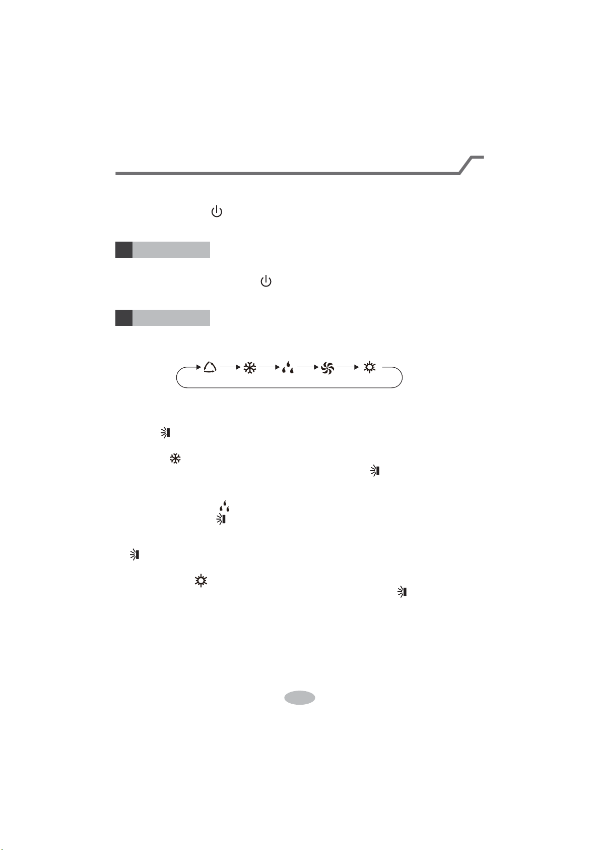
8
Ɣ:KHQVHOHFWLQJDXWRPRGHDLUFRQGLWLRQHUZLOOVWDUWDXWRRSHUDWLRQDFFRUGLQJWR
LQGRRUDPELHQWWHPSHUDWXUH6HWWHPSHUDWXUHFDQ¶WEHDGMXVWHGDQGZLOOQRW
EHGLVSOD\HGDVZHOO3UHVVF$1EXWWRQFDQDGMXVWIDQVSHHG
3UHVVEXWWRQFDQDGMXVWIDQEORZLQJDQJOH
Ɣ$IWHUVHOHFWLQJFRROPRGHDLUFRQGLWLRQHUZLOORSHUDWHXQGHUFRROPRGH&RRO
LQGLFDWRURQLQGRRUXQLWLV213UHVVRUEXWWRQWRDGMXVWVHWWHPSH
UDWXUH3UHVVF$1EXWWRQWRDGMXVWIDQVSHHG3UHVVEXWWRQWRDGMXVWIDQ
EORZLQJDQJOH
Ɣ:KHQVHOHFWLQJGU\PRGHWKHDLUFRQGLWLRQHURSHUDWHVDWORZVSHHGXQGHUGU\
PRGH'U\LQGLFDWRURQLQGRRUXQLWLV218QGHUGU\PRGHIDQVSHHGFDQ¶W
EHDGMXVWHG3UHVVEXWWRQWRDGMXVWIDQEORZLQJDQJOH
Ɣ:KHQVHOHFWLQJIDQPRGHWKHDLUFRQGLWLRQHUZLOORQO\EORZIDQQRFRROLQJDQG
QRKHDWLQJ$OOLQGLFDWRUVDUH2)F3UHVVF$1EXWWRQWRDGMXVWIDQVSHHG3UHVV
EXWWRQWRDGMXVWIDQEORZLQJDQJOH
Ɣ:KHQVHOHFWLQJKHDWLQJPRGHWKHDLUFRQGLWLRQHURSHUDWHVXQGHUKHDWPRGH
+HDWLQGLFDWRURQLQGRRUXQLWLV213UHVVRUEXWWRQWRDGMXVWVHW
WHPSHUDWXUH3UHVVFANEXWWRQWRDGMXVWIDQVSHHG3UHVVEXWWRQWRDGMXVW
IDQEORZLQJDQJOH&RROLQJRQO\XQLWZRQ¶WUHFHLYHKHDWLQJPRGHVLJQDO,IVHWWLQJ
KHDWPRGHZLWKUHPRWHFRQWUROOHUSUHVV212))EXWWRQFDQ¶WVWDUWXSWKHXQLW
Note:
Ɣ)RUSUHYHQWLQJFROGDLUDIWHUVWDUWLQJXSKHDWLQJPRGHLQGRRUXQLWZLOOGHOD\a
PLQXWHVWREORZDLUDFWXDOGHOD\WLPHLVGHSHQGRQLQGRRUDPELHQWWHPSHUDWXUH
Ɣ6HWWHPSHUDWXUHUDQJHIURPUHPRWHFRQWUROOHUa
ć
)DQVSHHGDXWRORZ
VSHHGPHGLXPVSHHGKLJKVSHHG
Introduction for buttons on remote controller
Note:
Ɣ$IWHUSXWWLQJWKURXJKWKHSRZHUWKHDLUFRQGLWLRQHUZLOOJLYHRXWDVRXQG
2SHUDWLRQLQGLFWRULV21UHGLQGLFDWRU$IWHUWKDW\RXFDQRSHUDWHWKHDLU
FRQGLWLRQHUE\XVLQJUHPRWHFRQWUROOHU
212))EXWWRQ
02'(EXWWRQ
1
2
3UHVVWKLVEXWWRQFDQWXUQRQRUWXUQRIIWKHDLUFRQGLWLRQHU$IWHUWXUQLQJRQWKHDLU
FRQGLWLRQHURSHUDWLRQLQGLFDWRURQLQGRRUXQLW¶VGLVSOD\LV21JUHHQLQGLFDWRU
7KHFRORXULVGLIIHUHQWIRUGLIIHUHQWPRGHOVDQGLQGRRUXQLWZLOOJLYHRXWDVRXQG
3UHVVWKLVEXWWRQWRVHOHFW\RXUUHTXLUHGRSHUDWLRQPRGH
$8T2&22/FAN'RY +(AT
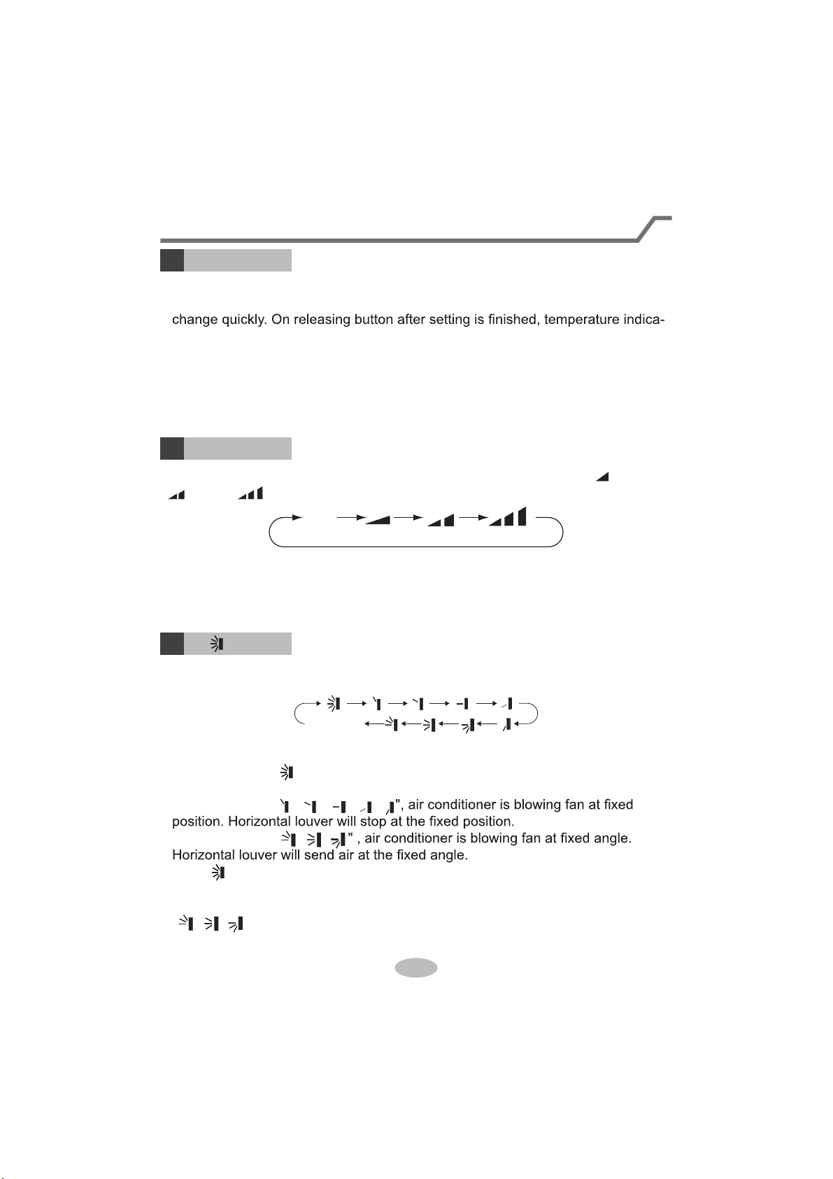
9
Introduction for buttons on remote controller
FAN button
4
Pressing this button can set fan speed circularly as: auto (AUTO), low( ), medium
( ), high( ).
Auto
Note:
Ɣ8QGHUAUTO speed,
Ɣ)DQVSHHGXQGHUGU\PRGHLVORZVSHHG
5
Press this button can select up&down swing angle. Fan blow angle can be selected
circularly as below:
Ɣ:KHQVHOHFWLQJDLUFRQGLWLRQHULVEORZLQJIDQDXWRPDWLFDOO\. Horizontal
louver will automatically swing up & down at maximum angle.
Ɣ:KHQVHOHFWLQJ
ǃǃǃǃ
Ɣ:KHQVHOHFWLQJ
ǃǃ
Ɣ+ROGEXWWRQDERYHVWRVHW\RXUUHTXLUHGVZLQJDQJOH:KHQUHDFKLQJ\RXU
required angle, release the button.
Note:
Ɣ
ǃǃ
PD\QRWEHDYDLODEOH:KHQDLUFRQGLWLRQHUUHFHLYHVWKLVsignal, the
air conditioner will blow fan automatically.
button
no display
(horizontal louvers stops
at current position)
+/- button
3
Ɣ3UHVVRUEXWWRQRQFHLQFUHDVHRUGHFUHDVHVHWWHPSHUDWXUH
ć
.
+ROGLQJRUEXWWRQVODWHr, set temperature on remote controller will
tor on indoor unit will change accordingly. (Temperature can’t be adjusted under
auto mode)
Ɣ:KHQVHWWLQJTIMER ON, TIMER OFF oU&/2&.SUHVVRUEXWWRQWR
adjust time. (Refer to CLOCK, TIMER ON, 7,0(52))EXWWRQV:KHQVHWWLQJ
TIMER ON, TIMER OFF or CLOCK, preVVRUEXWWRQWRDGMXVWWLPH5HIHU
to CLOCK, TIMER ON, TIMER OFF buttons)
the IDU fan motor will adjust the fan speed (high, medium or
low speed) according to ambient temperature.
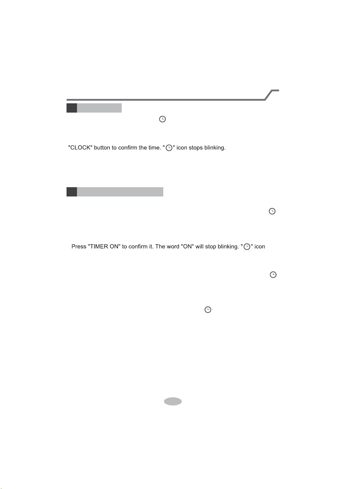
10
Press this button to set clock time. " " icon on remote controller will blink. Press
"+" or "-" button within 5s to set clock time. Each pressing of "+" or "-" button, clock
time will increase or decrease 1 minute. If hold "+" or "-" button, 2s later, time will
change quickly. Release this button when reaching your required time. Press
Note:
Ɣ&ORFNWLPHDGRSWVKRXUPRGH
ƔThe interval between two operation can’t exceeds 5s. Otherwise, remote contro-
ller will quit setting status. Operation for TIMER ON/TIMER OFF is the same.
&/O&K button
6
Introduction for buttons on remote controller
TIMER ON / TIMER OFF button
7
ƔTIMER ON button
"TIMER ON" button can set the time for timer on. After pressing this button, " "
icon disappears and the word "ON" on remote controller blinks. Press "+" or "-"
button to adjust TIMER ON setting. After each pressing "+" or "-" button, TIMER
ON setting will increase or decrease 1min. Hold "+" or "-" button, 2s later, the
time will change quickly until reaching your required time.
UHVXPHVGLVSOD\LQJ&DQFHOTIMER ON: Under the condition that TIMER ON is
started up, press "TIMER ON" button to cancel it.
ƔTIMER OFF button
"TIMER OFF" button can set the time for timer off. After pressing this button," "
icon disappears and the word "OFF" on remote controller blinks. Press "+" or "-"
button to adjust TIMER OFF setting. After each pressing "+" or "-" button, TIMER
OFF setting will increase or decrease 1min. Hold "+" or "-" button, 2s later, the
time will change quickly until reaching your required time.
Press "TIMER OFF" word "OFF" will stop blinking. " " icon resumes displaying.
&DQFHOTIMER OFF. Under the condition that TIMER OFF is started up, press
"TIMER OFF" button to cancel it.
Note:
Ɣ8QGHURQDQGRff status, you can set TIMER OFF or TIMER ON simultaneously.
Ɣ%HIRUHVHWWLQJTIMER ON or TIMER OFF, please adjust the clock time.
ƔAfter starting up TIMER ON or TIMER OFF, set the constant circulating valid.
After that, air conditioner will be turned on or turned off according to setting time.
ON/OFF button has no effect on setting. If you don’t need this function, please
use remote controller to cancel it.
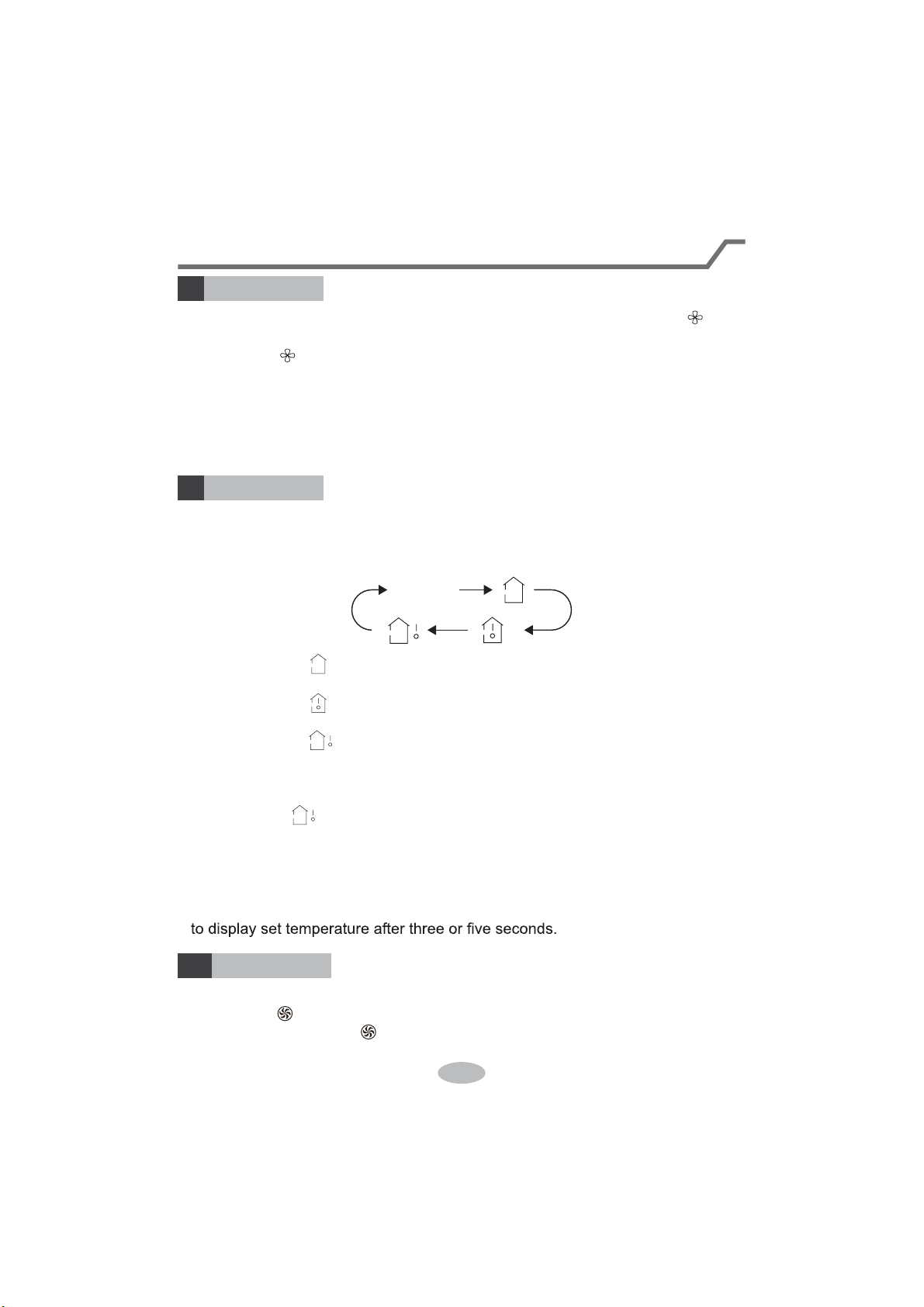
11
TEMP button
9
Introduction for buttons on remote controller
By pressing this button, you can see indoor set temperature, indoor ambient temp-
erature or outdoor ambient temperature on indoor unit’s display. The setting on
remote controlleris selected circularly as below:
no display
Ɣ:KHQVHOHFWLQJRUQRGLVSOD\ZLWKUHPRWHFRQWUROOHr, temperature indicator
on indoor unit displays set temperature.
Ɣ:KHQVHOHFWLQJZLWKUHPRWHFRQWUROOHr, temperature indicator on indoor unit
displays indoor ambient temperature.
Ɣ:KHQVHOHFWLQJZLWKUHPRWHFRQWUROOHr, temperature indicator on indoor unit
displays outdoor ambient temperature.
Note:
Ɣ
Outdoor temperature display is not available for some models. At that time, indoor
XQLWUHFHLYHVsignal, while it displays indoor set temperature.
Ɣ,W’s defaulted to display set temperature when turning on the unit.There is no
display in the remote controller.
Ɣ2QO\IRUWKHPRGHOVZKRVHLQGRRUXQLWKDVGXDOGLVSODy.
Ɣ:KHQVHOHFWLQJGLVSOD\LQJRILQGRRURURXWGRRUDPELHQWWHPSHUDWXUHLQGRRU
temperature indicator displays corresponding temperature and automatically turn
X-FAN button
8
3UHVVWKLVEXWWRQXQGHUFRRODQGGU\PRGHWRVWDUWXS[IDQIXQFWLRQDQGLFRQ
on remote controller will be displayed. Press this button again to cancel x-fan
IXQFWLRQDQGLFRQZLOOGLVDSSHDr.
Note:
Ɣ:KHQ[IDQIXQFWLRQLVRQLIWKHDLUFRQGLWLRQHULVWXUQHGRIf, indoor fan will still
operate at low speed for a while to blow the residual water inside the air duct.
Ɣ'XULQJ[IDQRSHUDWLRQSUHVV;FAN button to turn ofI[IDQIXQFWLRQ,QGRRUIDQ
will stop operation immediately.
TURBO button
10
Under COOL or HEAT mode, press this button to turn to quick COOL or quick
HEATPRGHLFRQLVGLVSOD\HGRQUHPRWHFRQWUROOHr. Press this button again
WRH[LWWXUERIXQFWLRQDQGLFRQZLOOGLVDSSHDr.

12
Function introduction for combination buttons
Child lock function
Press "+" and "-" simultaneously to turn on or turn off child lock function. When
child lock function is on, " " icon is displayed on remote controller. If you operate
the remote controller, the " " icon will blink three times without sending signal to
the unit.
Temperature display switchover function
Under OFF status, press "-" and "MODE" buttons simultaneously to switch temp-
erature display between
ć
and
.
Introduction for buttons on remote controller
Press this button to turn off display light on indoor unit. " " icon on remote
controller disappears. Press this button again to turn on display light. " " icon is
displayed.
Under COOL, HEAT or DRY mode, press this button to start up sleep function.
" " icon is displayed on remote controller. Press this button again to cancel sleep
function and " " icon will disappear.
SLEEP button
LIGHT button
11
12

13
1.
After putting through the power, press "ON/OFF" button on remote controller to
turn on the air conditioner.
2.
Press "MODE" button to select your required mode: AUTO, COOL, DRY, FAN,
HEAT.
3.
Press "+" or "-" button to set your required temperature. (Temperature can’t be
adjusted under auto mode).
4.
Press "FAN" button to set your required fan speed: auto, low, medium and high
speed.
5.
Press " " button to select fan blowing angle.
Operation guide
Replacement of batteries in remote controller
1. Press the back side of remote controller marked
the cover of battery box along the arrow direction.
2. Replace two 7# (AAA 1.5V) dry batteries, and
make sure the position of "+" polar and "-" polar
are correct.
3. Reinstall the cover of battery box.
signal sender battery
Cover of battery box
remove
reinstall
Ɣ'XULQJRSHUDWLRQSRLQWWKHUHPRWHFRntrol signal sender at the receiving
window on indoor unit.
ƔThe distance between signal sender and receiving window should be no
more than 8m, and there should be no obstacles between them.
or wireless telephone; remote controller should be close to indoor unit during
operation.
Ɣ5HSODFHQHZEDWWHULHVRIWKHVDPHPRGHOZKHQUHSODFHPHQWLVUHTXLUHG
Ɣ:KHQ\RXGRQ¶WXVHUHPRWHFRQWUROOHUIRUDORQJWLPHSOHDVHWDNHRXWWKH
batteries.
Ɣ,IWKHGLVSOD\RQUHPRWHFRQWUROOHULVIX]]\RUWKHUH’s no display, please
replace batteries.
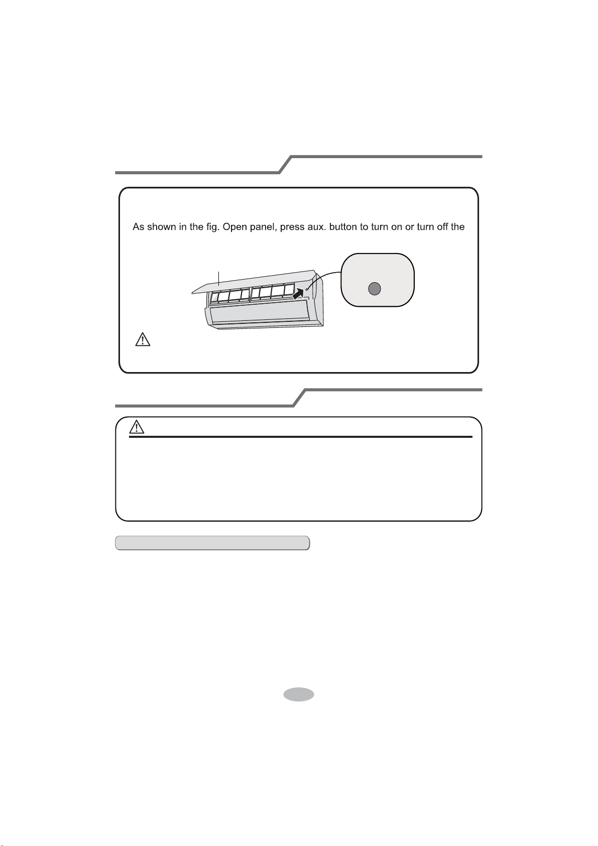
14
Emergency operation
Clean and maintenance
air conditioner. When the air conditioner is turned on, it will operate under
auto mode.
aux. button
panel
WARNING:
Use insulated object to press the auto button
If remote controller is lost or damaged, please use auxiliary button to turn
on or turn of
f the air conditioner. The operation in details are as below:
WARNING
NOTICE:
Ŷ Turn off the air conditioner and disconnect the power before cleaning the air
conditioner to avoid electric shock.
Ŷ'RQRWZDVKWKHDLUFRQGLWLRQHUZLWKZDWHUWRDYRLGHOHFWULFVKRFN
Ŷ'RQRWXVHYRODWLOHOLTXLGWRFOHDQWKHDLUFRQGLWLRQHr.
Clean surface of indoor unit
When the surface of indoor unit is dirty, it is recommended to use a soft dry cloth
or wet cloth to wipe it.
Ɣ'RQRWUHPRYHWKHSDQHOZKHQFOHDQLQJLW
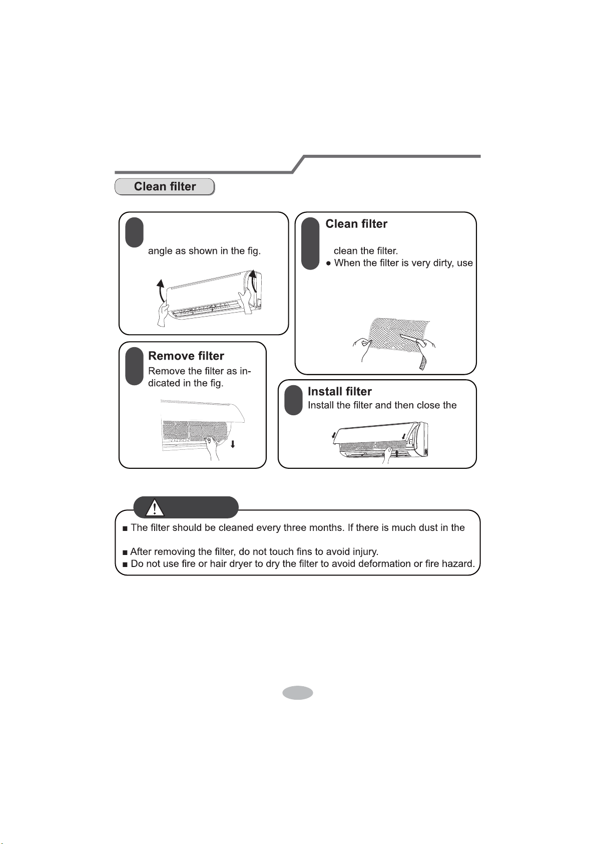
Clean and maintenance
1
2
3
4
Open panel
Pull out the panel to a certain Ɣ8VHGXVWFDWFKHURUZDWHUWR
WKHZDWHUEHORZ
ć
) to clean
LWDQGWKHQSXWLWLQDVKDG\
DQGFRROSODFHWRGU\.
panel cover tightl\.
RSHUDWLRQHQYLURQPHQWFOHDQIUHTXHQF\FDQEHLQFUHDVHG
WARNING
Clean and maintenance
Notice for recovery
1. Many packing materials are recyclable materials.
Please dispose them in appropriate recycling unit.
2. If you want to dispose the air conditioner, please contact local dealer or
consultant service center for the correct disposal method.
16
1. Check whether air inlets and air outlets are blocked.
2. Check whether air switch, plug and socket are in good condition.
4. Check whether mounting bracket for outdoor unit is damaged or corroded.
If yes, please contact dealer.
5. Check whether drainage pipe is damaged.
1. Disconnect power supply.
3. Check whether mounting bracket for outdoor unit is damaged or corroded.
If yes, please contact dealer.

Malfunction analysis
General phenomenon analysis
Please check below items before asking for maintenance. If the malfunction still
FDQ¶WEHHOLPLQDWHGSOHDVHFRQWDFWORFDOGHDOHURUTXDOL¿HGSURIHVVLRQDOV
Phenomenon Check items Solution
Indoor unit
FDQ¶WUHFHLYH
remote
FRQWUROOHU¶V
signal or
remote
controller
has no
action.
Ɣ:KHWKHULWVLQWHUIHUHGVHYHUHO\
(such as static electricity
,stable
voltage)?
Ɣ:KHWKHUUHPRWHFRQWUROOHULV
within the signal receiving
range?
Ɣ:KHWKHUWKHUHDUHREVWDFOHV"
Ɣ:KHWKHUUHPRWHFRQWUROOHULV
pointing at the receiving
window?
Ɣ,VVHQVLWLYLW\RIUHPRWHFRQWUR
OOHUORZIX]]\GLVSOD\DQGQR
display?
Ɣ1RGLVSOD\ZKHQRSHUDWLQJ
remote controller?
Ɣ)OXRUHVFHQWODPSLQURRP"
Ɣ3XOORXWWKHSOXJ5HLQVHUW
the plug after about 3min, and
then turn on the unit again.
Ɣ6LJQDOUHFHLYLQJUDQJHLVP
Ɣ5HPRYHREVWDFOHV
Ɣ
Select proper angle and point
the remote controller at the re-
ceiving window on indoor unit.
Ɣ&KHFNWKHEDWWHULHV,IWKH
power of batteries is too low,
please replace them.
Ɣ7DNHWKHUHPRWHFRQWUROOHU
close to indoor unit.
Ɣ7XUQRIIWKHÀXRUHVHQWODPS
and then try it again.
Ɣ&KHFNZKHWKHUUHPRWHFRQW
roller appears to be damaged.
If yes, replace it.
No air
emitted
from
indoor
unit
Ɣ$LULQOHWRUDLURXWOHWRILQGRRU
unit is blocked?
Ɣ(OLPLQDWHREVWDFOHV
Ɣ8QGHUKHDWLQJPRGHLQGRRU
temperature is reached to set
temperature?
Ɣ
$IWHUUHDFKLQJWRVHWWHPSHU
ature, indoor unit will stop bl-
owing out air.
Ɣ+HDWLQJPRGHLVWXUQHGRQMXVW
now?
Ɣ,QRUGHUWRSUHYHQWEORZLQJ
out cold air, indoor unit will be
started after delaying for sev-
eral minutes, which is a nor-
mal phenomenon.
17

Malfunction analysis
Ɣ3RZHUIDLOXUH"
Ɣ,VSOXJORRVH"
Ɣ&LUFXLWEUHDNWULSVRIIRU
fuse is burnt out?
Ɣ:LULQJKDVPDOIXQFWLRQ"
Ɣ8QLWKDVUHVWDUWHGLPPHGLDWHO\
after stopping operation?
Ɣ:KHWKHUWKHIXQFWLRQVHWWLQJ
for remote controller is
correct?
Ɣ5HVHWWKHIXQFWLRQ
Ɣ:DLWIRUPLQDQGWKHQWXUQ
on the unit again.
Ɣ$VNSURIHVVLRQDOWRUHSODFHLW
Ɣ$VNSURIHVVLRQDOWRUHSODFH
circuit break or fuse.
Ɣ5HLQVHUWWKHSOXJ
Ɣ:DLWXQWLOSRZHUUHFRYHU\
Air condit-
LRQHUFDQ¶W
operate
Mist is em-
itted from
LQGRRUXQLW¶V
air outlet
Ɣ,QGRRUWHPSHUDWXUHDQGKXP
idity is high?
Ɣ%HFDXVHLQGRRUDLULVFRROHG
rapidly. After a while, indoor
temperature and humidity will
be decrease and mist will
disappear.
Phenomenon Check items Solution
Set temper-
DWXUHFDQ¶W
be adjusted
Ɣ8QLWLVRSHUDWLQJXQGHUDXWR
mode?
Ɣ
7HPSHUDWXUHFDQ¶WEHDGMX
sted under auto mode.
Please switch the operation
mode if you need to adjust
temperature.
Ɣ<RXUUHTXLUHGWHPSHUDWXUH
exceeds the set temperature
range?
Ɣ6HWWHPSHUDWXUHUDQJH
16
ć
~30
ć
.
Cooling
(heating)
effect is
not good.
Ɣ9ROWDJHLVWRRORZ"
Ɣ:DLWXQWLOWKHYROWDJH
resumes normal.
Ɣ)LOWHULVGLUW\"Ɣ&OHDQWKH¿OWHU
Ɣ6HWWHPSHUDWXUHLVLQSURSHU
range?
Ɣ$GMXVWWHPSHUDWXUHWRSURSHU
range.
Ɣ'RRUDQGZLQGRZDUHRSHQ"Ɣ&ORVHGRRUDQGZLQGRZ
18
Phenomenon Check items Solution
Odours are
emitted
Ɣ:KHWKHUWKHUH¶VRGRXUVRXUFH
such as furniture and cigarette,
etc.
Ɣ(OLPLQDWHWKHRGRXUVRXUFH
Ɣ&OHDQWKH¿OWHU
Air conditio-
ner operates
abnormally
Ɣ:KHWKHUWKHUH¶VLQWHUIHUHQFH
such as thunder, wireless
devices, etc.
Ɣ'LVFRQQHFWSRZHUSXWEDFN
power, and then turn on the
unit again.
Outdoor
unit has
vapor
Ɣ+HDWLQJPRGHLVWXUQHGRQ"
Ɣ'XULQJGHIURVWLQJXQGHUKH
ating mode, it may generate
vapor
, which is a normal
phenomenon.
“Water
ÀRZLQJ´
noise
Ɣ$LUFRQGLWLRQHULVWXUQHGRQRU
turned of
f just now?
Ɣ7KHQRLVHLVWKHVRXQGRI
UHIULJHUDQWÀRZLQJLQVLGH
the unit, which is a normal
phenomenon.
Cracking
noise
Ɣ$LUFRQGLWLRQHULVWXUQHGRQRU
turned of
f just now?
Ɣ7KLVLVWKHVRXQGRIIULFWLRQ
caused by expansion and/or
contraction of panel or other
parts due to the change of
temperature.
Malfunction analysis
19
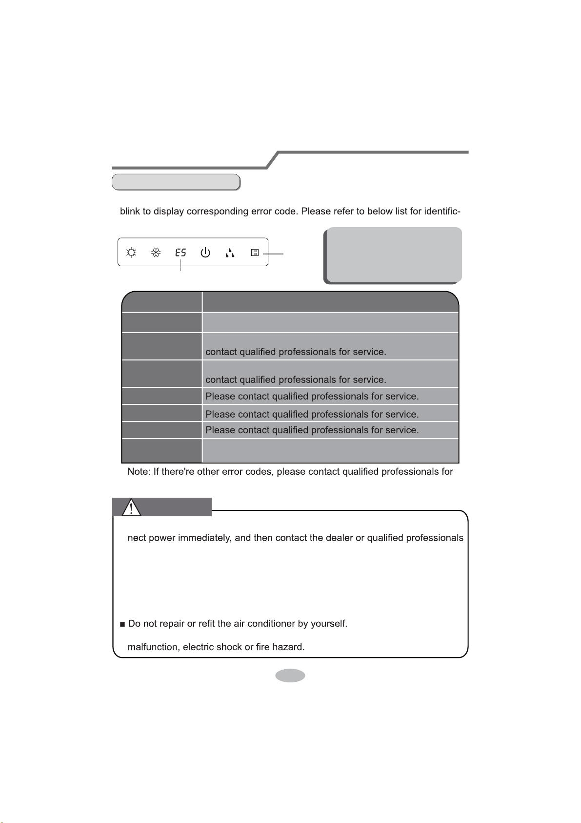
20
Malfunction analysis
Error Code
Ɣ When air conditioner status is abnormal, temperature indicator on indoor unit will
ation of error code.
Indoor
display
Error code
Above indicator diagram is only
for reference. Please refer to
actual product for the actual
indicator and position.
service.
Error code
E5
H6
C5
F1
F2
E6
Troubleshooting
t
It can be eliminated af er restarting the unit. If not, please
It can be eliminated after restarting the unit. If not, please
Means defrosting status. It’s the normal phenomenon.
Heating indicator
ON 10s OFF 0.5s
It can be eliminated after restarting the unit. If not, please
contact qualified professionals for service.
Ŷ:KHQEHORZSKHQRPHQRQRFFXUVSOease turn off air conditioner and discon-
for service.
Ɣ3RZHUFRUGLVRYHUKHDWLQJRUGDPDJHG
ƔThere’s abnormal sound during operation.
ƔAir switch trips off frequently.
ƔAir conditioner gives off burning smell.
Ɣ,QGRRUXQLWLVOHDNLQJ
Ŷ,IWKHDLUFRQGLWLRQHURSHUDWHVXQGHUDbnormal conditions, it may cause
WARNING
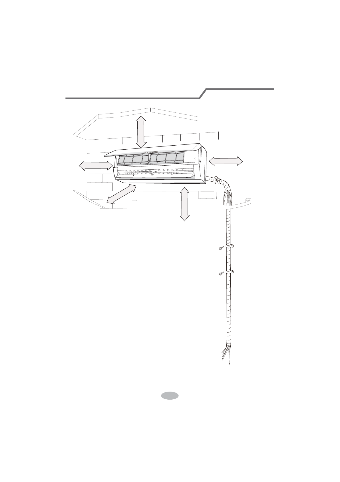
21
Installation dimension diagram
At least 250cm
At least 15cm
At least 300cm
6SDFHWRWKHÀRRU
Space to the ceiling
Space to the obstruction
At least 15cm
At least 15cm
Space to the wall
Space to the wall

22
Selection of installation location
Basic requirement
Installing the unit in the following pla-
ces maycause malfunction. If it is un-
avoidable, please consult the local
dealer:
1. There should be no obstruction near air
inlet and air outlet.
2. Select a location where the condensat-
ion water can be dispersed easily and
won't affect other people.
3. Select a location which is convenient to
connect the outdoor unit and near the
power socket.
4. Select a location which is out of reach
for children.
5.
The location should be able to withstand
the weight of indoor unit and won't incr-
ease noise and vibration.
6.
The appliance must be installed 2.5m
7. Don't install the indoor unit right above
the electric appliance.
Indoor unit
1.The place with strong heat sources,
,
8. Please try your best to keep way from
fluorescent lamp.
or volatile objects spread in the air.
2.The place with high-frequency
devices (such as welding machine,
medical equipment).
3.The place near coast area.
4.
The place with oil or fumes in the air.
5.The place with sulfureted gas.
6.Other places with special circums-
tances.
7.The appliance shall not be install-
ed in the laundry
Tools for installation
1 Level meter 2 Screw driver 3 Impact drill
4 Drill head 5 Pipe expander 6 Torque wrench
7 Open-end wrench 8 Pipe cutter 9 Leakage detector
10 Vacuum pump 11 Pressure meter 12 Universal meter
13 Inner hexagon spanner 14 Measuring tape
Note:
Ɣ3OHDVHFRQWDFWWKHORFDODJHQWIRULQVWDOODWLRQ
23
Requirements for electric connection
Safety precaution
Grounding requirement
1. Must follow the electric safety regulations when installing the unit.
circuit break.
3. Make sure the power supply matches with the requirement of air conditioner.
Unstable power supply or incorrect wiring or malfunction. Please install proper
power supply cables before using the air conditioner.
4. Properly connect the live wire, neutral wire and grounding wire of power socket.
5. Be sure to cut off the power supply before proceeding any work related to
electricity and safety.
7. If the supply cord is damaged, it must be replaced by the manufacturer, its
8. The temperature of refrigerant circuit will be high, please keep the interconnec-
tion cable away from the copper tube.
grounding with specialized grounding device by a professional. Please make
sure it is always grounded effectively, otherwise it may cause electric shock.
2. The yellow-green wire in air conditioner is grounding wire, which can't be used
for other purposes.
3. The grounding resistance should comply with national electric safety regulations.
4. The appliance must be positioned so that the plug is accessible.
5. An all-pole disconnection switch having a contact separation of at least 3mm in
6. Including an circuit break with suitable capacity, please note the following table.
Circuit break should be included magnet buckle and heating buckle function, it
can protect the circuit-short and overload. (Caution: please do not use the fuse
only for protect the circuit)
9. The appliance shall be installed in accordance with national wiring regulations.
10. Installation must be performed in accordance with the requirement of NEC
and CEC by authorized personnel only.
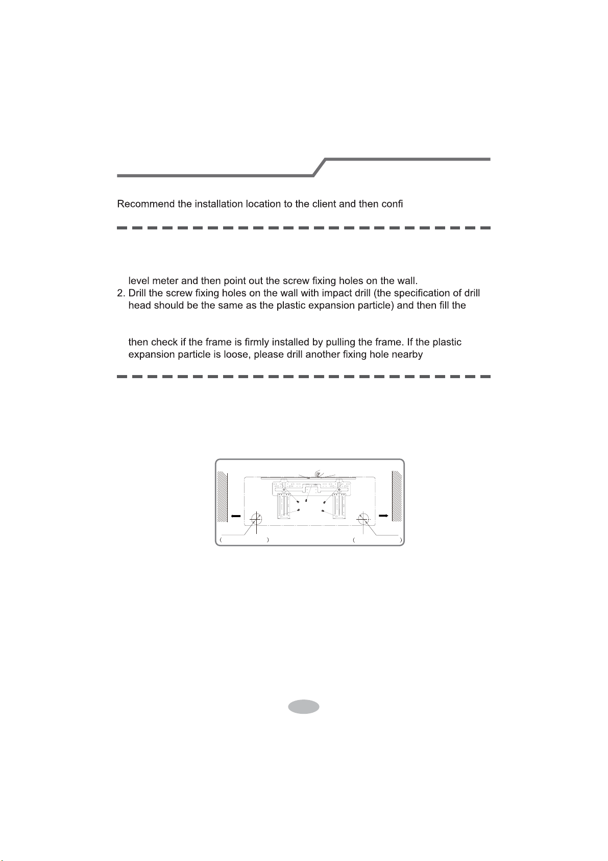
24
Installation of indoor unit
Step one: choosing installation location
Step two: install wall-mounting frame
rm it with the client.
1. Hang the wall-mounting frame on the wall; adjust it in horizontal position with the
plastic expansion particles in the holes.
3. Fix the wall-mounting frame on the wall with tapping screws (ST4.2X25TA) and
.
1. Choose the position of piping hole according to the direction of outlet pipe. The
position of piping hole should be a little lower than the wall-mounted frame,
shown as below.
Step three: open piping hole
2. Open a piping hole with the diameter ofĭRQWKHVHOHFWHGRXWOHWSLSH
position. In order to drain smoothly, slant the piping hole on the wall slightly
GRZQZDUGWRWKHRXWGRRUVLGHZLWKWKHJUDGLHQWRI
Left
Wall
ĭPP
Right
Mark in the middle of it
Level meter
Rear piping hole
Wall
Space
to the
wall
above
PP
Space
to the
wall
above
PP
ĭPP
Rear piping hole
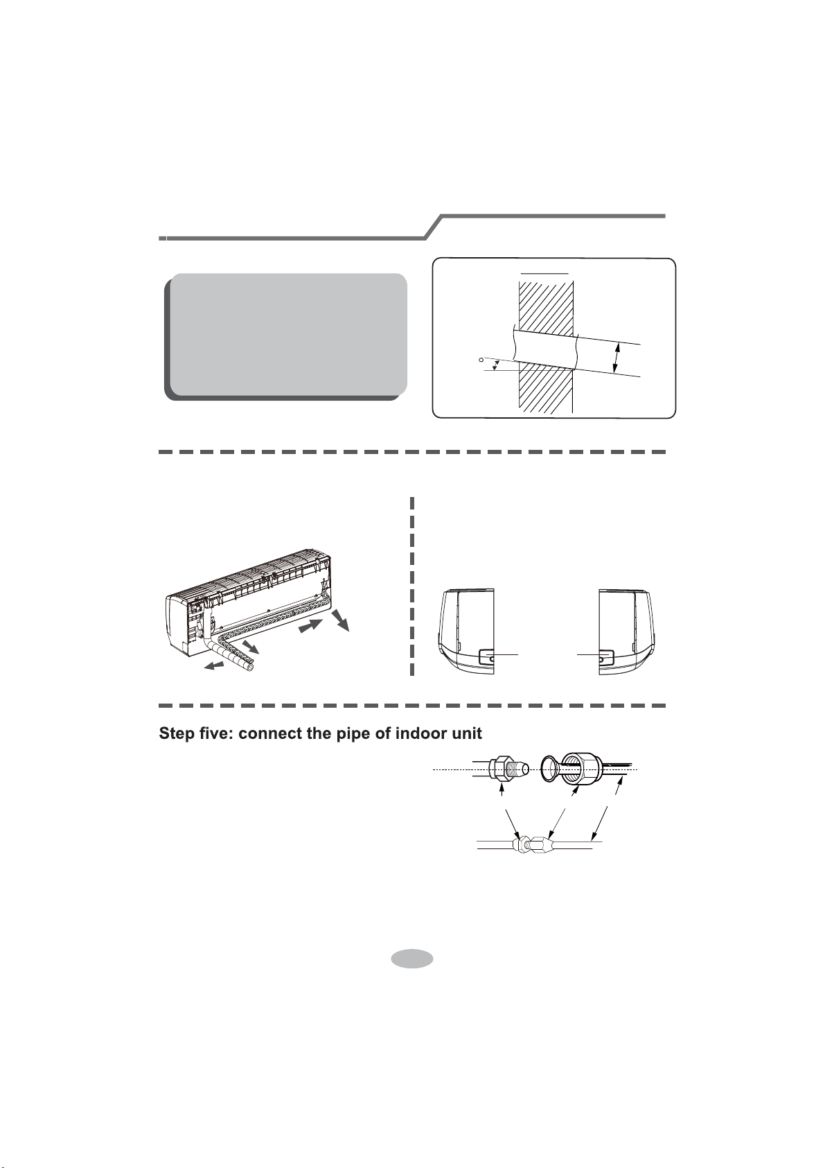
25
1. Aim the pipe joint at the corresponding
bellmouth.
2. Pretightening the union nut with hand.
3. Adjust the torque force by referring to the following sheet. Place the open-end
wrench on the pipe joint and place the torque wrench on the union nut. Tighten
the union nut with torque wrench.
2. When select leading out the pipe
from left or right, please cut off the
corresponding hole on the bottom
case.
cut off
the hole
left right
1. The pipe can be led out in the
direction of right, rear right, left or
rear left.
left
rear left
right
rear right
Step four: outlet pipe
Installation of indoor unit
union nutpipe joint
pipe
Note:
Ɣ3D\DWWHQWLRQWRGXVWSUHYHQWLRQDQG
WDNHUHOHYDQWVDIHW\PHDVXUHVZKHQ
opening the hole.
ƔThe plastic expansion particles are
QRWSURYLGHGDQGVKRXOGEHERXJKW
locally.
Indoor
5-10
outdoor
ĭ

26
nection pipe with insulating pipe, and
insulating pipe
1. Connect the drain hose to the outlet pipe of
outlet
pipe
drain hose
drain hose
tape
outlet pipe
drain hose
insulating pipe
ƔAdd insulating pipe in the indoor
ƔThe plastic expansion particles are
1. Open the panel, remove the screw
on the wiring cover and then take
wiring cover
screw
panel
Step seven: connect wire of indoor unit
4. Wrap the indoor pipe and joint of con-
then wrap it with tape.
Step six: install drain hose
Installation of indoor unit
torque wrench
open-end
wrench
indoor pipe
pipe
union nut
Hex nut diameter Tightening torque (N
.
m)
ĭ
ĭ
ĭ
ĭ
ĭ
30~40
45~55
60~65
70~75
15~20
indoor unit.
2. Bind the joint with tape.
Note:
drain hose in order to prevent
condensation.
not provided.
down the cover.
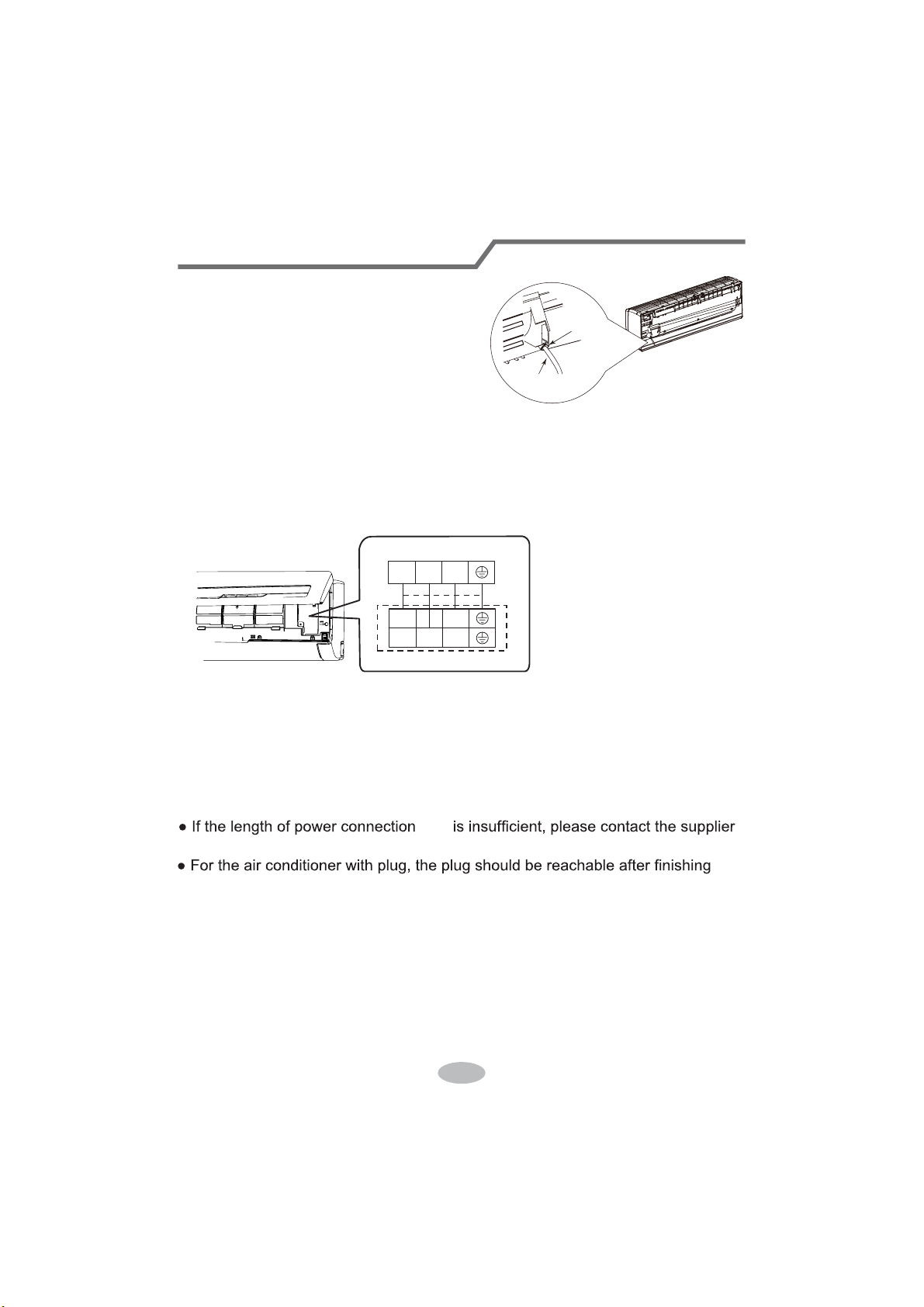
27
4. Put wiring cover back and then tighten the screw.
5. Close the panel.
Installation of indoor unit
Note:
ƔAll wires of indoor unit and outdoor unit should be connected by a professional.
for a new one. Avoid extending the cord by yourself.
3. Remove the wire clip; connect the power connection cord to the wiring terminal
with wire clip.
power connection
cord
cable-cross
hole
2. Make the power connection cord go
through the cable-cross hole at the back
of indoor unit and then pull it out from
the front side.
23N(1)
Outdoor unit connection
L2L1
23N(1)
cord
according to the color ;tighten the screws and then fix the power connection cord
fixed by the wire clip inside of the electric box first before connecting the power
connection cord.
If there is no wired controller in the product you bought ,you should put the wire
installation.
Ɣ)RUWKHDLUFRQGLWLRQHUZLWKRXWSOXJDQcircuit break must be installed in the line.
The air switch should be all-pole parting and the contact parting distance should
be more than 3mm.

28
Installation of indoor unit
Step eight: bind up pipe
1. Bind up the connection pipe, power
cord and drain hose with the band.
indoor unit
gas
pipe
indoor and
outdoor power cord
liquid pipe
drain hose
band
2. Reserve a certain length of drain
hose and power cord for installation
when binding them. When binding to
a certain degree, separate the indoor
power and then separate the drain
hose.
3. Bind them evenly.
4. The liquid pipe and gas pipe should
be bound separately at the end.
Note:
Ɣ7KHSRZHUFRUGDQGFRQWUROZLUH
FDQWEHFURVVHGRUZLQGLQJ
Ɣ7KHGUDLQKRVHVKRXOGEHERXQG
at the bottom.
drain hose
band
connection pipe
indoor power cord
Step nine: hang the indoor unit
1. Put the bound pipes in the wall pipe and then make them pass through the wall
hole.
2. Hang the indoor unit on the wall-mounting frame.
3. Stuff the gap between pipes and wall hole with sealing gum.
4. Fix the wall pipe.
5. Check if the indoor unit is installed firmly and closed to the wall.
Note:
Ɣ'RQRWEHQGWKHGUDLQKRVHWRRH[FHVVLYHO\LQRUGHUWRSUHYHQWEORFNLQJ
indoor
outdoor
wall pipe
sealing gum
upper hook
lower hook of
wall-mounting frame
29
Check after installation
Test operation
Ɣ&KHFNDFFRUGLQJWRWKHIROORZLQJUHTXLUHPHQWDIWHU¿QLVKLQJLQVWDOODWLRQ
Items to be checked Possible malfunction
+DVWKHXQLWEHHQLQVWDOOHG¿UPO\"The unit may drop, shake or emit noise.
Have you done the refrigerant leakage
test?
,WPD\FDXVHLQVXI¿FLHQWFRROLQJ
(heating) capacity.
,VKHDWLQVXODWLRQRISLSHOLQHVXI¿FLHQW"
It may cause condensation and water
dripping.
Is water drained well?
It may cause condensation and water
dripping.
Is the voltage of power supply accord-
ing to the voltage marked on the
nameplate?
It may cause malfunction or damaging
the parts.
Is electric wiring and pipeline installed
correctly?
It may cause malfunction or damaging
the parts.
Is the unit grounded securely? It may cause electric leakage.
Does the power cord follow the speci-
¿FDWLRQ"
It may cause malfunction or damaging
the parts.
Is there any obstruction in the air inlet
and outlet?
,WPD\FDXVHLQVXI¿FLHQWFRROLQJ
(heating) capacity.
The dust and sundries caused during
installation are removed?
It may cause malfunction or damaging
the parts.
The gas valve and liquid valve of
connection pipe are open completely?
,WPD\FDXVHLQVXI¿FLHQWFRROLQJ
(heating) capacity.
1. Preparation of test operation
Ɣ7KHFOLHQWDSSURYHVWKHDLUFRQGLWLRQHU
Ɣ6SHFLI\WKHLPSRUWDQWQRWHVIRUDLUFRQGLWLRQHUWRWKHFOLHQW
2. Method of test operation
Ɣ3XWWKURXJKWKHSRZHUSUHVV212))EXWWRQRQWKHUHPRWHFRQWUROOHUWRVWDUW
operation.
Ɣ3UHVV02'(EXWWRQWRVHOHFW$872&22/'5<)$1DQG+($7WRFKHFN
whether the operation is normal or not.
Ɣ,IWKHDPELHQWWHPSHUDWXUHLVORZHUWKDQ
ć
, the air conditioner can’t
start cooling.
30
1. Standard length of connection pipe
ƔPPP
4. The additional refrigerant oil and refrigerant charging required after prolonging
connection pipe
Ɣ$IWHUWKHOHQJWKRIFRQQHFWLRQSLSHLVSURORQJHGIRUPDWWKHEDVLVRI
VWDQGDUGOHQJWK\RXVKRXOGDGGPORIUHIULJHUDQWRLOIRUHDFKDGGLWLRQDOP
of connection pipe.
Ɣ The calculation Pethod of additional refrigerant charging DPount (on the Easis
of liquid pipe):
ƔBasing on the length of standard pipe, add refrigerant according to the
requirement as shown in the table. 7KHDGGLWLRQDOUHIULJHUDQWFKDUJLQJDPRXQW
SHUPHWHULVGLfIHUHQWDFFRUGLQJWRWKHGLDPHWHURIOLTXLGSLSH6HHWKH
following sheet.
$GGLWLRQDOUHIULJHUDQWFKDUJLQJDPRXQW= prolonged length of liquid pipe ×
DGGLWLRQDOUHIULJHUDQWFKDUJLQJDPRXQWSHUPHWHU
Cooling
FDSDFLW\
Cooling
FDSDFLW\
%WXK
:
%WXK
:
%WXK
:
%WXK
:
%WXK
:
%WXK
:
%WXK
:
%WXK
:
%WXK
:
%WXK
:
Max height
difference
Max height
difference
Max length
of connec-
tion pipe
Max length
of connec-
tion pipe
10
10
20
20 10 20
10 20
0LQOHQJWKRIFRQQHFWLRQSLSHLVP
0D[OHQJWKRIFRQQHFWLRQSLSHDQGPD[KLJKGLfference.
Configuration of connection pipe

31
Additional refrigerant charging amount for R22, R407C, R410A and R134a
Diameter of connection pipe
Liquid pipe(mm) Gas pipe(mm)
ĭ
ĭRUĭ
ĭRUĭ
ĭ
ĭ
ĭ
ĭ
ĭRUĭ
ĭRUĭ
ĭRUĭ
_
_
Cooling only(g/m) Cooling and heating(g/m)
15
15
30
60
250 250
350350
120
120
50
20
Outdoor unit throttle
&RQ¿JXUDWLRQRIFRQQHFWLRQSLSH

32
Pipe expanding method
Note:
Improper pipe expanding is the main cause of refrigerant leakage. Please expand
the pipe according to the following steps:
A: Cut the pipe
Ɣ&RQ¿UPWKHSLSHOHQJWKDFFRUGLQJWR
the distance of indoor unit and
outdoor unit.
Ɣ&XWWKHUHTXLUHGSLSHZLWKSLSHFXWWHU
pipe
pipe cutter
leaning uneven burr
B: Remove the burrs
Ɣ5HPRYHWKHEXUUVZLWKVKDSHUDQG
prevent the burrs from getting into
the pipe.
downwards
pipe
shaper
C: Put on suitable insulating pipe
D: Put on the union nut
Ɣ5HPRYHWKHXQLRQQXWRQWKHLQGRRU
connection pipe and outdoor valve;
install the union nut on the pipe.
union pipe
pipe
E: Expand the port
Ɣ([SDQGWKHSRUWZLWKH[SDQGHU
Note:
Ɣ$LVGLIIHUHQWDFFRUGLQJWRWKH
diameter, please refer to the sheet
below:
expander
hard
mold
pipe
F: Inspection
Ɣ&KHFNWKHTXDOLW\RIH[SDQGLQJSRUW
If there is any blemish, expand the
port again according to the steps
above.
the length is equal
improper expanding
leaning
damaged
surface
crack uneven
thickness
smooth surface
Outer diameter
(mm)
A(mm)
Max Min
ĭ
ĭ
ĭ
ĭ
1.3 0.7
1.6 1.0
1.8 1.0
2.4 2.2
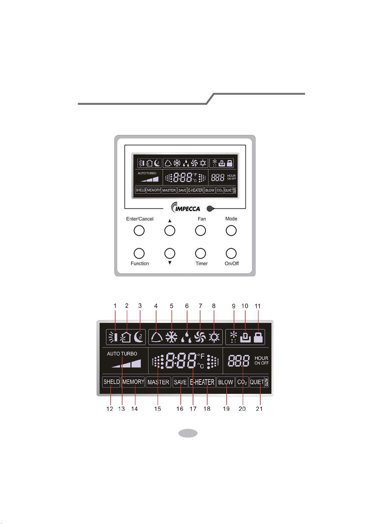
1 Displaying Part
Fig1.1.1 Outline of wired controller
1.1 LCD Display of Wired Controller
Fig.1.1.2 LCD display
33
If the product you bought is equipped with wired controller, please
refer to the following introductions of wired controller.
Wired Controller (Optional)

1.2 Instruction to LCD Display
Table 1.1
No. Symbols Description
1
Swing function
2
Air exchange function (this function is yet unavailable for this unit).
3
Sleep function (Only sleep 1).
4
Each kind of running mode of indoor unit (auto mode)
5
Cooling mode
6
Dry mode
7
Fan mode
8
Heating mode
9
Defrosting function for the outdoor unit.
10
Gate-control function (this function is yet unavailable for this unit).
11
Lock function.
12 SHIELD
Shield functions (Button operation, temperature setting, On/Off operation,
Mode setting are disabled by the remote monitoring system.)
13 Turbo Turbo function state
14 MEMORY
Memory function (The indoor unit resumes the original setting state after
power failure and then power recovery).
15
It blinks under on state of the unit without operation of any button.
16
SAVE
Energy-saving function (this function is yet unavailable for this unit).
17
Ambient/setting temperature value
18 E-HEATER Electric auxiliary heating function.
19 BLOW Blow function.
20
Timing value.
21 QUIET
Quiet function (two types: quiet and auto quiet)
(this function is yet unavailable for this unit).
34
Wired Controller (Optional)
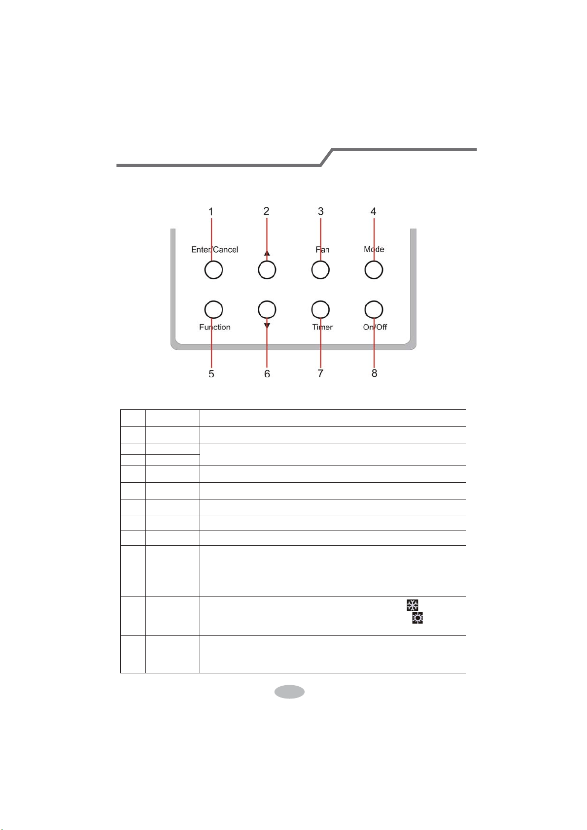
2 Buttons
2.1 Layout of Buttons
2.2 Functions of Buttons
Table 2.1
No. Name Function
1 Enter/Cancel Function selection and cancellation.
2 Ÿ
ķ.
Running temperature setting of the indoor unit, range:16~30
o
C.
ĸ.
Timer setting, range:0.5-24 hr.
6 ź
3 Fan Setting of the high/middle/low/auto fan speed.
4 Mode Setting of the Cooling/Heating/Fan/Dry/Auto mode of the indoor unit.
5 Function Switchover among the functions of Turbo/Save/E-heater/Blow etc..
7 Timer Timer setting.
8 On/Off Turn on/off the indoor unit
4+2 Ÿ0RGH
Press them for 5s under off state of the unit to enter/cancel the Memory
function(If memory is set, indoor unit after power failure and then power
recovery will resume the original setting state. If not, the indoor unit is
defaulted to be off after power recovery. Memory off is default before
delivery.).
3+6 )DQź
By pressing them at the same time under off state of the unit,
will be
displayed on the wired controller for the cooling only unit, while
will be
displayed on the wired controller for the cooling and heating unit.
2+6 Ÿź
Upon startup of the unit without malfunction or under off state of the
unit,press them at the same time for 5s to enter the lock state, in which
case,any other buttons won’t respond the press. Repress them for 5s to quit
this state.
35
Wired Controller (Optional)
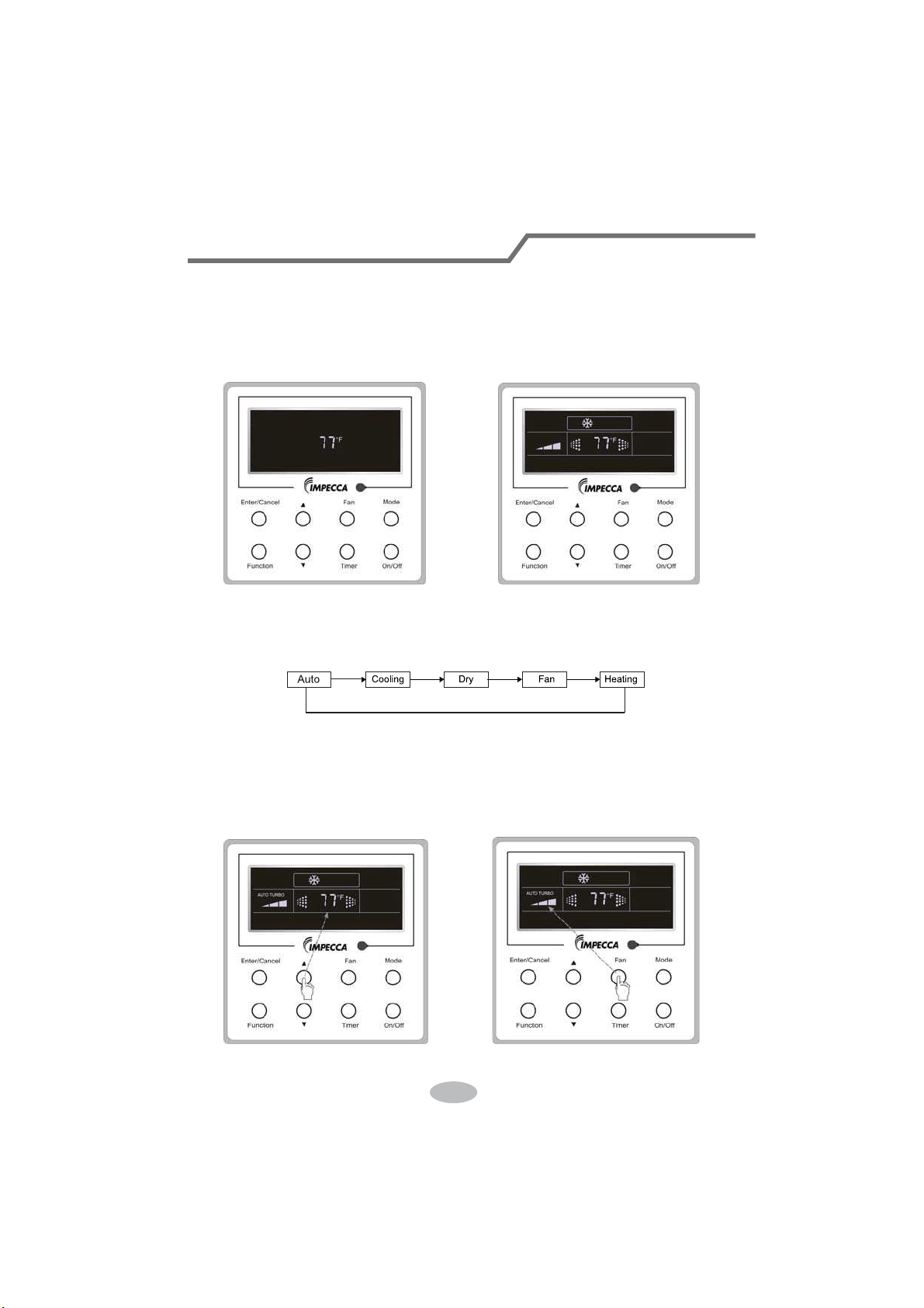
3 Operation Instructions
3.1 On/Off
Press On/Off to turn on the unit and turn it off by another press.
Note: The state shown in Fig.3.1.1 indicates the “Off” state of the unit after power on. The state
shown in Fig.3.1.2 indicates the “On” state of the unit after power on.
Fig.3.1.1 “Off” State Fig.3.1.2 “On” State
3.2 Mode Setting
Under ON state of the unit, press the Mode to switch the operation modes as the following
sequence: Auto–Cooling–Dry–Fan–Heating.
3.3 Temperature Setting
Press Ÿor źto increase/decrease the preset temperature. If pressing either of them
continuously, the temperature will be increased or decreased by 1°C every 0.5s,as shown in
Fig.3.3.1.
In the Cooling, Dry, Fan or Heating mode, the temperature setting range is 16°C~30°C.
In the Auto mode, the setting temperature is unadjustable.
Fig.3.3.1 Fig.3.4.1
36
Wired Controller (Optional)
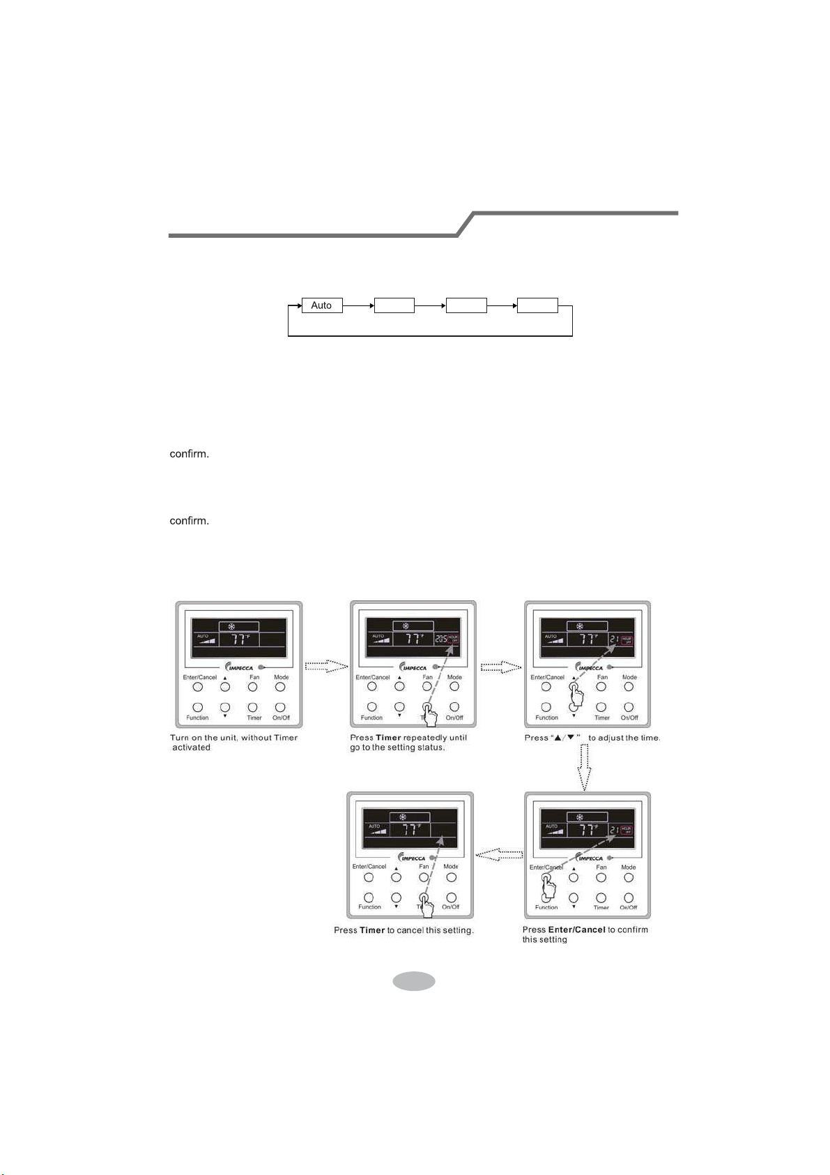
3.4 Fan Setting
Under the “On” state of the unit, press Fan and then fan speed of the indoor unit will change
circularly as shown in Fig.3.4.1.
Low Middle
High
3.5 Timer Setting
Under on-state of the unit, Press Timer button to set timer off of the unit. Under off-state of the
unit, press Timer button to set timer on of the unit in the same way.
Timer on setting:
Under off-state of the unit without timer setting, if Timer button is pressed, LCD will display xx.
Hour,with ON blinking. In this case, SUHVVŸor źbutton to adjust timer on and then press Timer to
Timer off setting:
Under on-state of the unit without timer setting, if Timer button is pressed, LCD will display xx.
HourZLWK2))EOLQNLQJ,QWKLVFDVHSUHVVŸRUźEXWWRQWRDGMXVWWLPHURQDQGWKHQSUHVVTimer to
&DQFHOWLPHU
After setting of timer, if Timer button is pressed, LCD won’t display xx. Hour so that timer setting
is canceled.
Timer off setting under the “On” state of the unit is shown as Fig.3.5.1.
Fig.3.5.1 Timer off Setting under the “On” State of the Unit
37
Wired Controller (Optional)

Timer on setting under the “Off” state of the unit is shown as Fig.3.5.2.
Fig.3.5.2 Timer on Setting under the “Off” State of the Unit
Timer range: 0.5-24hr. Every press of ŸRUźwill make the set time increased or decreased by
0.5hr. If either of them is pressed continuously, the set time will increase/ decrease by 0.5hr every
0.5s.
38
Wired Controller (Optional)
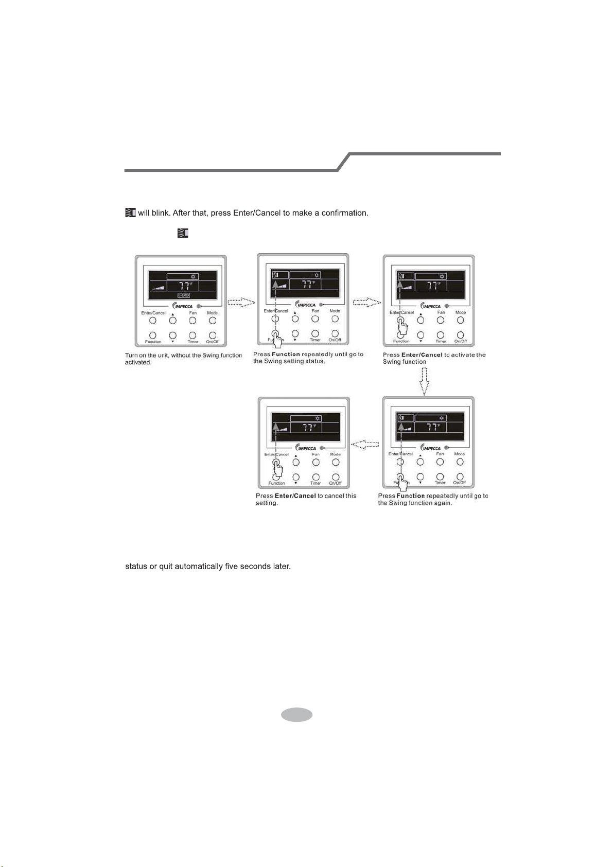
3.6 Swing Setting
Swing On: Press Function under on state of the unit to activate the swing function. In this case,
Swing Off: When the Swing function is on, press Function to enter the Swing setting
interface,with
blinking. After that, press Enter/Cancel to cancel this function. Swing setting is
shown as Fig.3.6.1.
Fig.3.6.1 Swing Setting
Notes:
ķ.
Sleep, Turbo or Blow setting is the same as the Swing setting.
ĸ.
After the setting has been done, it has to press the key “Enter/Cancel” to back to the setting
39
Wired Controller (Optional)
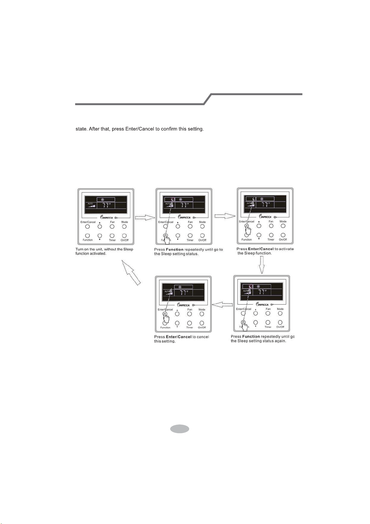
3.7 Sleep Setting
Sleep on: Press Function under the On state of the unit till the unit enters the Sleep setting
Sleep off: When the Sleep function is activated, press Function to enter the Sleep setting
status. After that, press Enter/Cancel to cancel this function.
In the Cooling or Dry mode, the temperature will increase by 1°C after the unit runs under
Sleep1 for 1hr and 1°C after another 1hr.After that, the unit will run at this temperature.
In the Heating mode, the temperature will decrease by 1°C after the unit runs under Sleep 1 for
1hr and 1°C after another 1hr. After that, the unit will run at this temperature.
Sleep setting is shown as Fig.3.7.1.
Fig.3.7.1. Sleep Setting
40
Wired Controller (Optional)
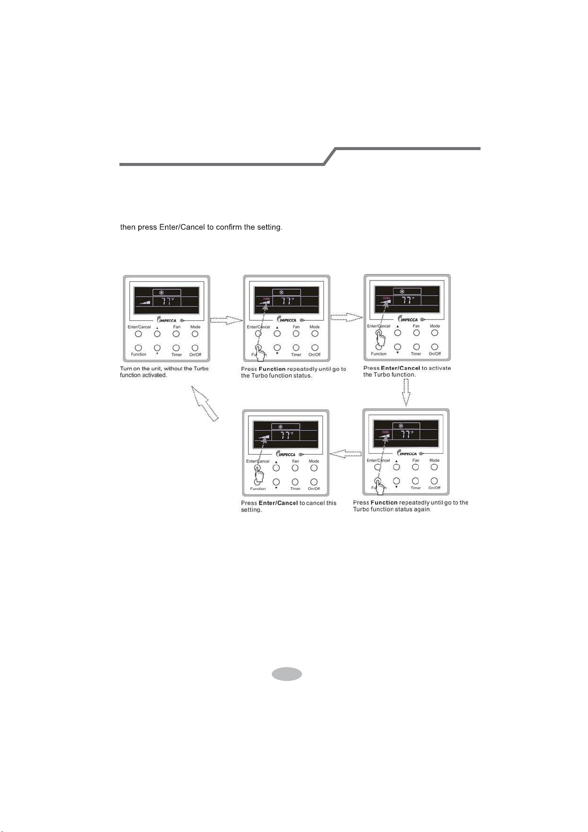
3.8 Turbo Setting
Turbo function: The unit at the high fan speed can realize quick cooling or heating so that the
room temperature can quickly approach the setting value.
In the Cooling or Heating mode, press Function till the unit enters the Turbo setting status and
When the Turbo function is activated, press Function to enter the Turbo setting status and then
press Enter/Cancel to cancel this function.
Turbo function setting is as shown in Fig.3.8.1.
Fig.3.8.1 Turbo Setting
41
Wired Controller (Optional)
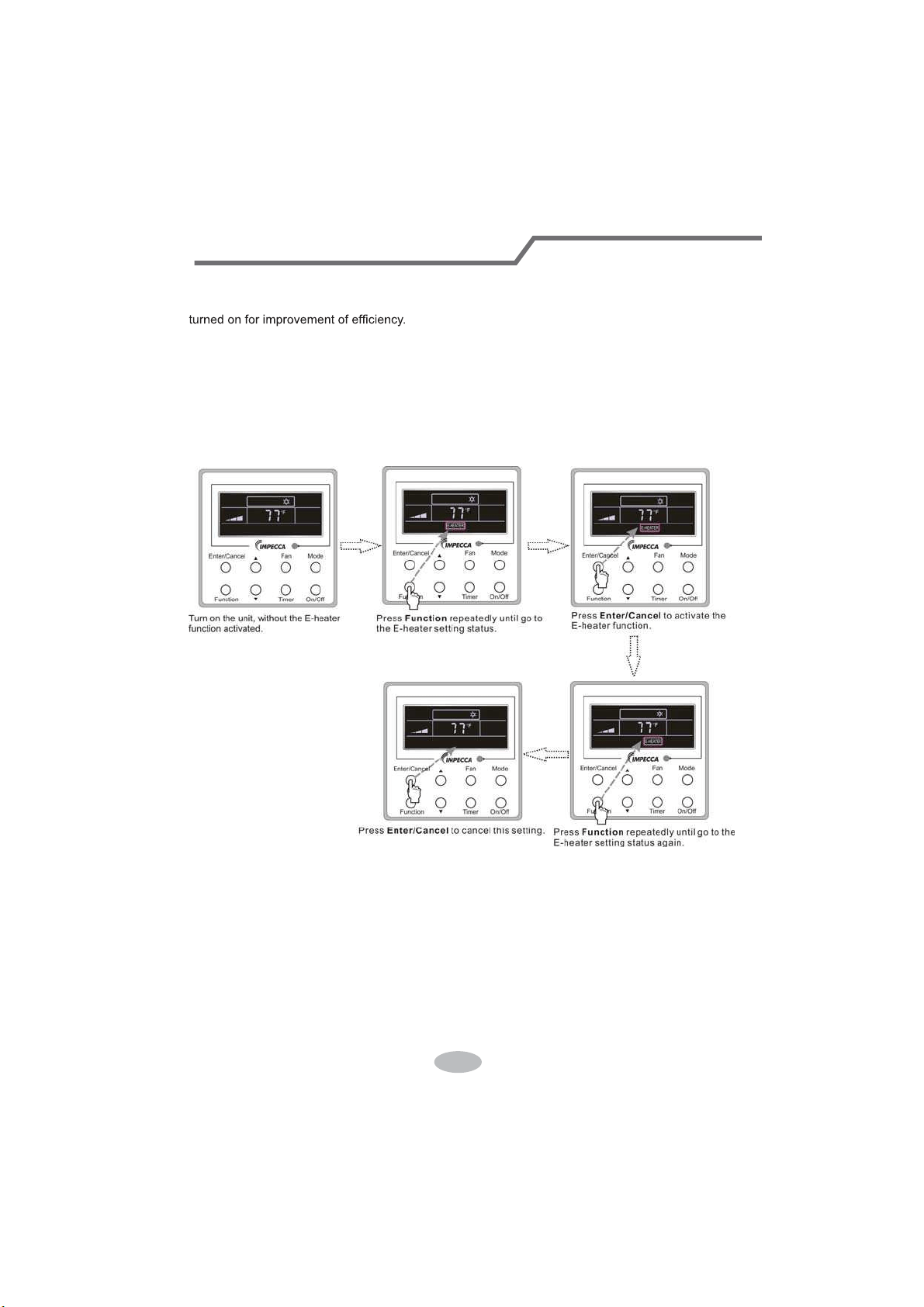
3.9 E-heater Setting
E-heater (auxiliary electric heating function): In the Heating mode, E-heater is allowed to be
Once the wired controller or the remote controller enters the Heating mode, this function will be
turned on automatically.
Press Function in the Heating mode to enter the E-heater setting interface and then press
Enter/Cancel to cancel this function.
Press Function to enter the E-heater setting status, if the E-heater function is not activated,
and then press Enter/Cancel to activate it.
The setting of this function is shown as Fig.3.9.1 below:
Fig.3.9.1 E-heater Setting
42
Wired Controller (Optional)
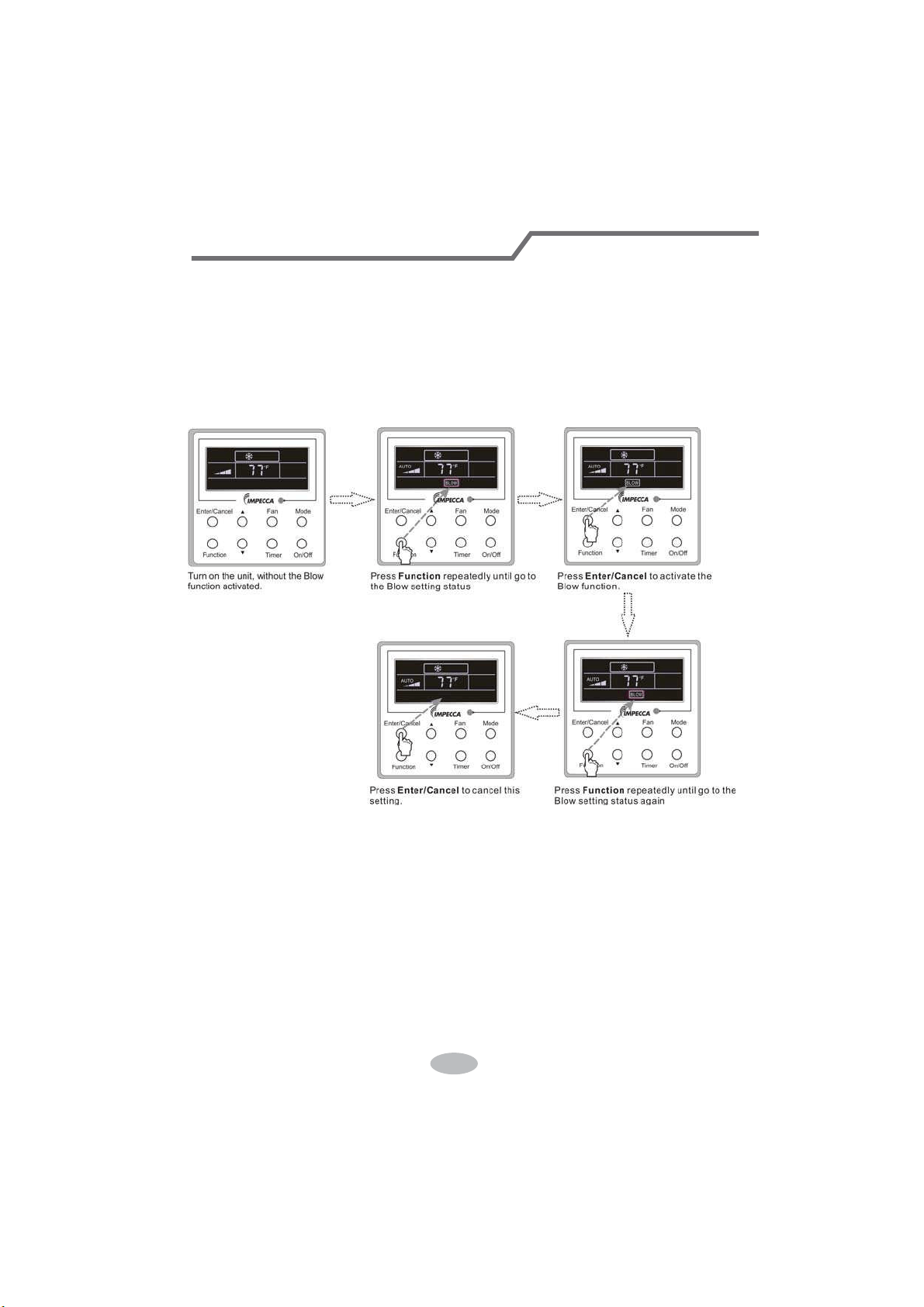
3.10 Blow Setting
Blow function: After the unit is turned off, the water in evaporator of indoor unit will be
automatically evaporated to avoid mildew.
In the Cooling or Dry mode, press Function till the unit enters the Blow setting status and then
press Enter/Cancel to active this function.
When the Blow function is activated, press Function to the Blow setting status and then press
Enter/Cancel to cancel this function.
Blow function setting is as shown in Fig.3.10.1
Fig.3.10.1 Blow Setting
Notes:
ķ.
When the Blow function is activated, if turning off the unit by pressing On/Off or by the
remote controller, the indoor fan will run at the low fan speed for 2 min, with “BLOW” displayed on
the LCD. While, if the Blow function is deactivated, the indoor fan will be turned off directly.
ĸ.
Blow function is unavailable in the Fan or Heating mode.
43
Wired Controller (Optional)
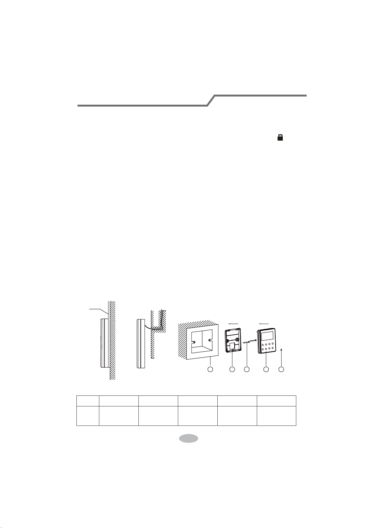
3.11 Other Functions
a. Lock
Upon startup of the unit without malfunction or under the “Off” state of the unit, press Ÿand źat
the same time for 5s till the wired controller enters the Lock function. In this case, LCD displays
.
After that, repress these two buttons at the same time for 5s to quit this function.
Under the Lock state, any other button press won’t get any response.
b. Memory
Memory switchover: Under the “Off” state of the unit, press Mode and Ÿat the same time for
5s to switch memory states between memory on and memory off. When this function is activated,
Memory will be displayed. If this function is not set, the unit will be under the “Off” state after power
failure and then power recovery.
Memory recovery: If this function has been set for the wired controller, the wired controller after
power failure will resume its original running state upon power recovery. Memory contents: On/
Off, Mode, set temperature, set fan speed and Lock function.
4 Installation and Dismantlement
4.1 Connection of the Signal Line of the Wired Controller
Ɣ2SHQWKHFRYHURIWKHHOHFWULFFRQWUROER[RIWKHLQGRRUXQLW
Ɣ/HWWKHVLQJOHOLQHRIWKHZLUHGFRQWUROOHUWKURXJKWKHUXEEHUULQJ
Ɣ&RQQHFWWKHVLJQDOOLQHRIWKHZLUHGFRQWUROWRWKHSLQVRFNHWRIWKHLQGRRUXQLW3&%
ƔTighten the signal wire with ties.
ƔThe communication distance between the main board and the wired controller can be up to
20 meters ( the standard distance is 8 meters)
4.2 Installation of the Wired Controller
1
39&3LSH
3 4 52
Fig.4.1 Accessories for the Installation of the Wired Controller
Table 4.1
No. 1 2 3 4 5
Name
6RFNHWER[
embedded
in the wall
Soleplate of
the Wired
Controller
Screw
M4X25
)URQW3DQHO
of the Wired
Controller
Screw
ST 2.9X6
44
Wired Controller (Optional)
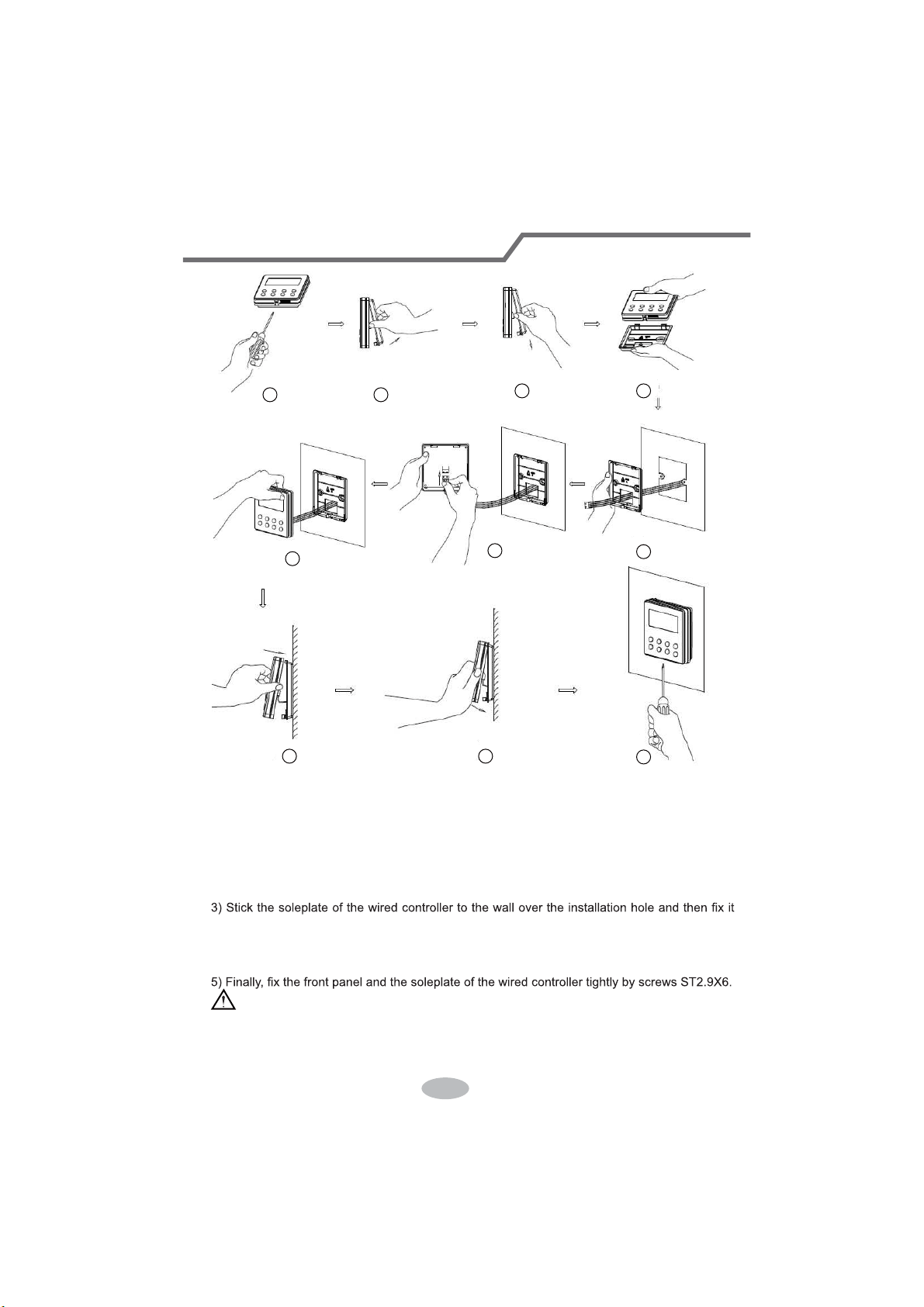
1
6
8 9
10
7
3 4
5
2
Fig.4.2
Fig.4.2 shows the installation steps of the wired controller, but there are some issues that need
your attention.
1) Prior to the installation, please firstly cut off the power supply of the wire buried in the
installation hole, that is, no operation is allowed with electricity during the whole installation.
2) Pull out the four-core twisted pair line from the installation holes and then let it go through
the rectangular hole behind the soleplate of the wired controller.
with screws M4X25.
4) Insert the four-core twisted pair line into the slot of the wired controller and then buckle the
front panel and the soleplate of the wired controller together.
CAUTION!
Please pay special attention to the followings during the connection to avoid the malfunction of
the air conditioning unit due to electromagnetic interference.
ķ.
Separate the signal and communication lines of the wired controller from the power cord
45
Wired Controller (Optional)
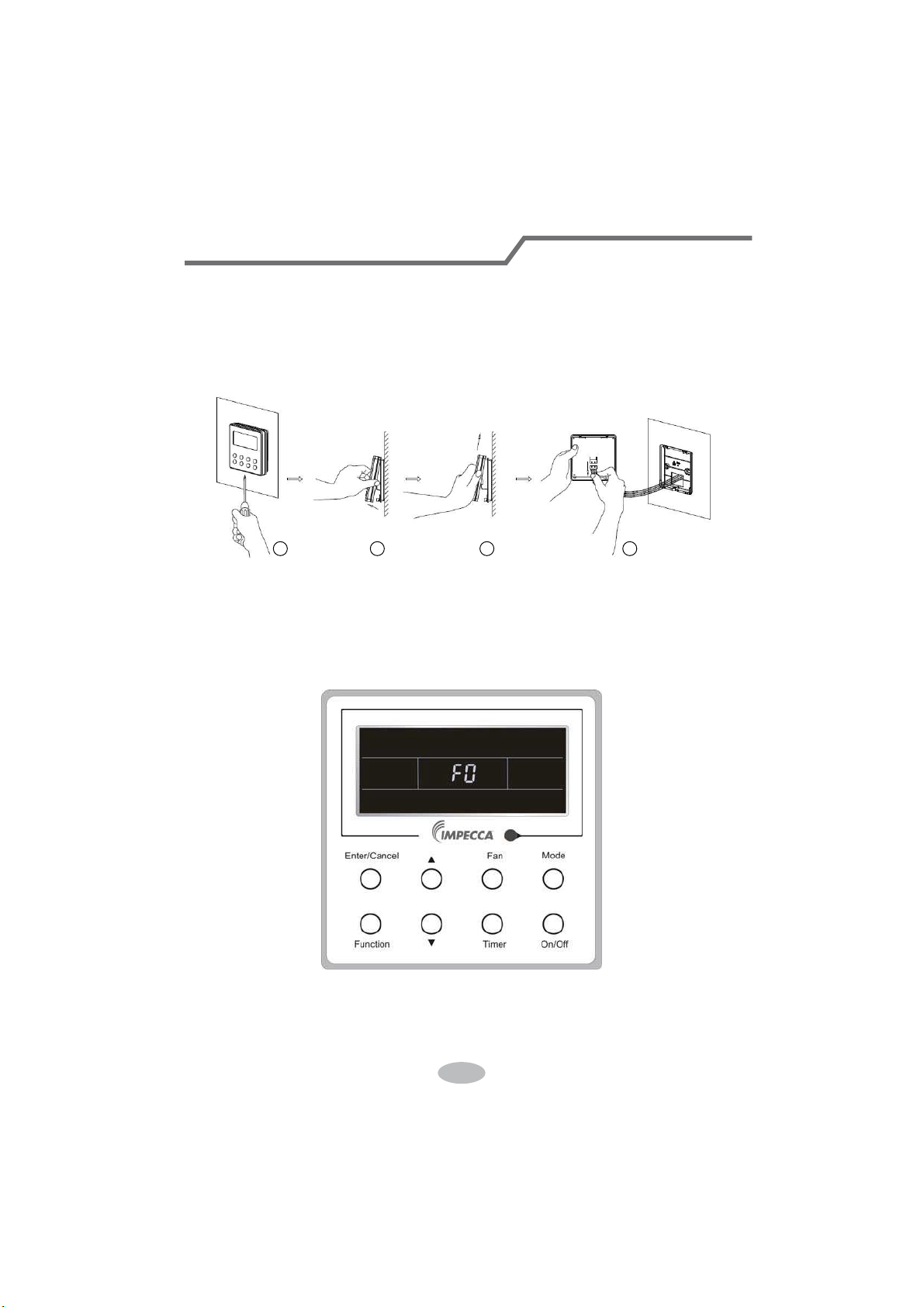
and connection lines between the indoor and outdoor unit, with a minimum interval of 20cm,
otherwise the communication of the unit will probably work abnormally.
ĸ.
If the air conditioning unit is installed where is vulnerable to electromagnetic
interference,then the signal and communication lines of the wired controller must be the shielding
twisted pair lines.
4.3 Dismantlement of the Wired Controller
1 3 42
5 Errors Display
If there is an error occurring during the operation of the system, the error code will be displayed
on the LCD, as show in Fig.5.1. If multi errors occur at the same time, their codes will be displayed
circularly.
Note: In event of any error, please turn off the unit and contact the professionally skilled
personnel.
Fig.5.1
46
Wired Controller (Optional)
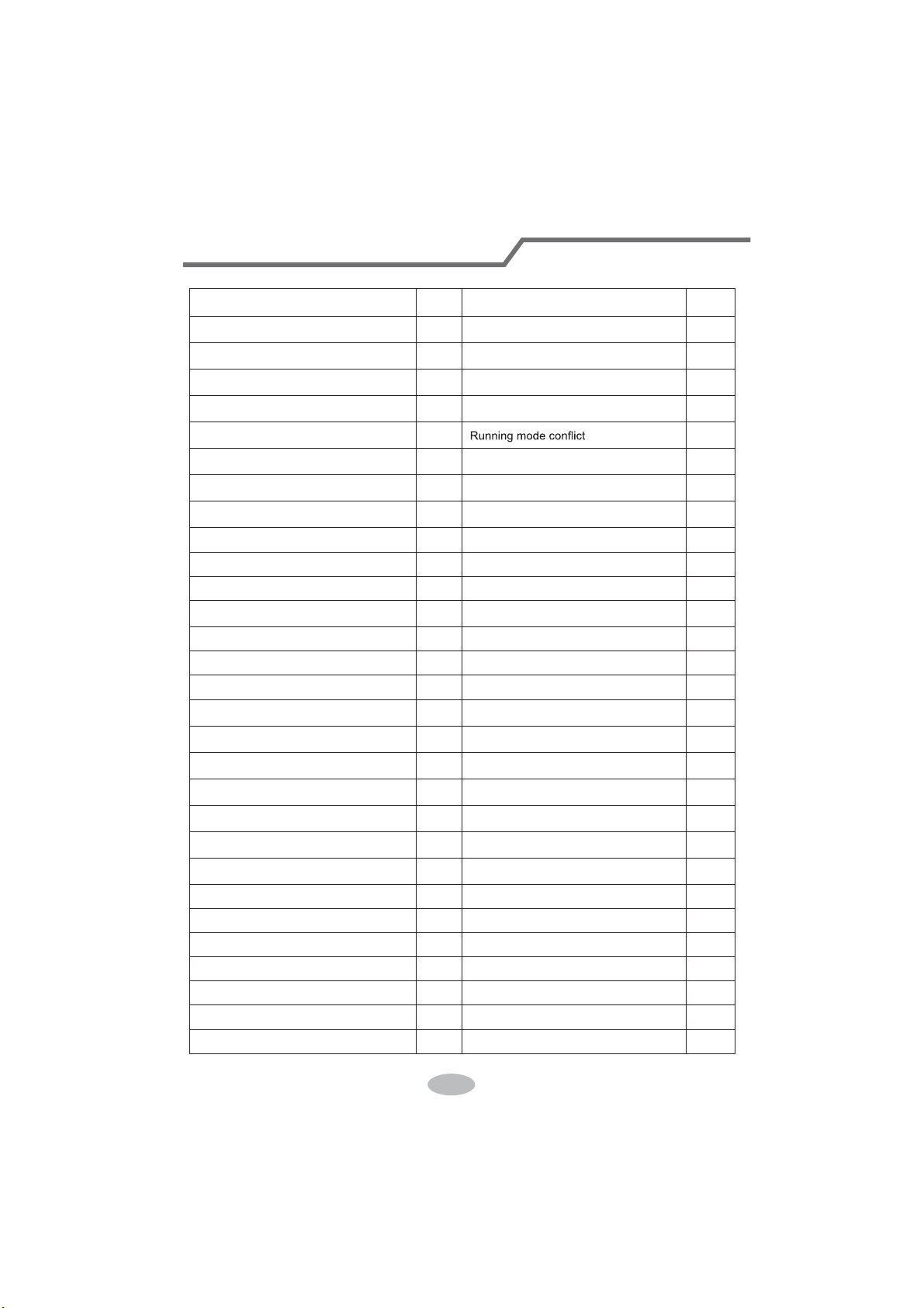
Table 5.1 Meaning of Each Error
Error
Error
Code
Error
Error
Code
Return air temperature sensor open/
short circuited
F1 Drive board communication error P6
evaporator temperature sensor open/
short circuited
F2 Compressor overheating protection H3
Indoor unit liquid valve temperature
sensor open/short circuited
b5 Indoor and outdoor units unmatched LP
Indoor gas valve temperature sensor
open/ short circuited
b7
Communication line misconnected or
expansion valve error
dn
IPM temperature sensor open/short
circuited
P7
E7
Outdoor ambient temperature sensor
open/ short circuited
F3 Pump-down Fo
Outdoor unit condenser mid-tube
temperature sensor open/short circuited
F4 Jumper error C5
Discharge temperature sensor open/
short circuited
F5 Forced defrosting H1
Indoor and outdoor communication error E6 Compressor startup failure Lc
DC bus under-voltage protection PL High discharge temperature protection E4
DC bus over-voltage protection PH Overload protection E8
Compressor phase current sensing
circuit error
U1 Whole unit over-current protection E5
Compressor demagnetization protection HE Over phase current protection P5
PFC protection Hc Compressor desynchronizing H7
IPM Temperature Protection P8 IPM Current protection H5
Over-power protection L9
Compressor phase loss/reversal
protection
Ld
System charge shortage or blockage
protection
F0
Frequency restricted/reduced with whole
unit current protection
F8
Capacitor charging error PU
Frequency restricted/reduced with IPM
current protection
En
High pressure protection E1
Frequency restricted/reduced with high
discharge temperature
F9
Low pressure protection E3
Frequency restricted/reduced with anti-
freezing protection
FH
Compressor stalling LE
Frequency restricted/reduced with
overload protection
F6
Over-speeding LF
Frequency restricted/reduced with IPM
temperature protection
EU
Drive board temperature sensor error PF Indoor unit full water error E9
AC contactor protection P9 Anti-freezing protection E2
Temperature drift protection PE AC input voltage abnormal PP
Sensor connection protection Pd Whole unit current sensing circuit error U5
DC bus voltage drop error U3 4-way valve reversing error U7
Outdoor fan 1 error protection L3 Motor stalling H6
Outdoor fan 2 error protection LA PG motor zero-crossing protection U8
47
Wired Controller (Optional)

CUSTOMER SUPPORT
Before contacting customer support, please see the troubleshooting guide above.
Visit our website to contact us, find answers to Frequently Asked Questions, and for other
resources which may include an updated version of this user's guide.
WWW.IMPECCA.COM
If you wish to contact us by phone, please be sure to have your model number and serial
number ready and call us between 9:00am and 6:00pm ET, at +1 866-954-4440.
Keep tabs on Impecca's newest innovations & enter contests via our social network feeds:
www.facebook.com/Impecca/
www.instagram.com/impecca/
@impeccausa

© 2016 Impecca, a division of LT Inc., Wilkes Barre, PA.

Split Air Conditioner
Models:
ISMI-W182
ISMI-W242
Thank you for choosing our product.
For proper operation, please read and keep this manual carefully.
If you have lost the Owner’s Manual, please contact the local agent or visit
www.impecca.com for electronic version.
v. 1.1

This appliance is not intended for use by persons (including children) with reduced physical,
sensory
or mental capabilities or lack of experience and knowledge, unless they have been given supervision
or instruction concerning use of the appliance by a person responsible for their safety.
Children should be supervised to ensure they are away from the appliance.
Content
Operation Notices
Precautions............................................................................................................1
Parts Name............................................................................................................6
Screen Operation Guide
Buttons on remote controller .................................................................................7
Introduction for icons on display screen................................................................7
Introduction for buttons on remote controller ........................................................ 8
Function introduction for combination buttons .....................................................12
Operation guide...................................................................................................
.13
Replacement of batteries in remote controller .....................................................
13
Emergency operation ...........................................................................................14
Maintenance
Clean and Maintenance.......................................................................................14
Malfunction
Malfunction analysis ............................................................................................17
Installation Notice
Installation dimension diagram............................................................................21
Tools for installation.............................................................................................22
Selection of installation location ..........................................................................22
Requirements for electric connection ..................................................................23
Installation
Installation of indoor unit......................................................................................24
Check after installation ........................................................................................
29
Test and operation
Test operation
Configuration of connection pipe
......................................................................................................29
Attachment
.........................................................................30
Pipe expanding method.......................................................................................32
Wired Controller....................................................................................................33
Explanation of Symbols
Indicates a hazardous situation that, if not avoided, will
result in death or serious injury.
Indicates a hazardous situation that, if not avoided, could
result in death or serious injury.
Indicates a hazardous situation that, if not avoided, may
result in minor or moderate injury.
Indicates important but not hazard-related information,
used to indicate risk of property damage.
Indicates a hazard that would be assigned a signal word
WARNING or CAUTION.
Precautions
WARNING
Do not connect air conditioner to multi-purpose socket.
This appliance can be used by children aged from 8
Operation and Maintenance
If the supply cord is damaged, it must be replaced by
the manufacturer, its service agent or similarly qualified
persons in order to avoid a hazard.
Do not spray water on indoor unit. It may cause electric
shock or malfunction.
Otherwise, it may cause fire hazard.
Children shall not play with the appliance.
Cleaning and user maintenance shall not be made by
children without supervision.
years and above and persons with reduced physical,
sensory or mental capabilities or lack of experience
and knowledge if they have been given supervision or
instruction concerning use of the appliance in a safe
way and understand the hazards involved.
Do not wash the air conditioner with water to avoid
electric shock.
After removing the filter, do not touch fins to avoid injury.
Do not use fire or hair dryer to dry the filter to avoid
deformation or fire hazard.
Do disconnect power supply when cleaning air
conditioner. Otherwise, it may cause electric shock.
1

Do not block air outlet or air inlet. It may cause
malfunction.
remote controller may be broken.
Ɣ Power cord is overheating or damaged.
Ɣ There’s abnormal sound during operation.
Ɣ Circuit break trips off frequently.
Ɣ Air conditioner gives off burning smell.
Ɣ Indoor unit is leaking.
contact the dealer or qualified professionals for service.
When turning on or turning off the unit by emergency
operation switch, please press this switch with an insulating
object other than metal.
outlet. It may cause personal injury or damage.
Precautions
WARNING
conditioner and disconnect power immediately, and then
If the air conditioner operates under abnormal conditions,
it may cause malfunction, electric shock or fire hazard.
Do not spill water on the remote controller, otherwise the
electric shock or damage. Please contact dealer when
you need to repair air conditioner.
Do not repair air conditioner by yourself. It may cause
objects. It may cause damage or personal injury.
Do not step on top panel of outdoor unit, or put heavy
When below phenomenon occurs, please turn off air
Do not extend fingers or objects into air inlet or air
Maintenance must be performed by qualified
professionals. Otherwise, it may cause personal injury
or damage.
2

Do install the circuit break. If not, it may cause malfunction.
of at least 3mm in all poles should be connected in fixed
wiring.
magnet buckle
and heating buckle function, it can protect
the circuit-short and
overload.
power supply circuit and circuit break.
Precautions
WARNING
note
the following table.Air switch should be included
Make sure the power supply matches with the
requirement of air conditioner.Unstable power supply or
incorrect wiring or malfunction. Please install proper power
supply cables before using the air conditioner.
An all-pole disconnection switch having a contact separation
Must follow the electric safety regulations when installing
the unit.
grounding wire of power socket.
Properly connect the live wire, neutral wire and
any work related to electricity and safety.
Be sure to cut off the power supply before proceeding
Including an circuit break with suitable capacity, please
Air Conditioner should be properly grounded. Incorrect
Don't use unqualified power cord.
grounding may cause electric shock.
According to the local safety regulations, use qualified
Installation must be performed by qualified professionals.
Otherwise, it may cause personal injury or damage.
Attachment
3
Installation must be performed in accordance with the
persons in order to avoid a hazard.
must be properly grounding with specialized grounding
device by a professional. Please make sure it is always
grounded effectively, otherwise it may cause electric shock.
The appliance must be positioned so that the plug is
accessible.
If the length of power connection wire is insufficient, please
contact the supplier for a new one. Avoid extending the
wire by yourself.
All wires of indoor unit and outdoor unit should be
connected by a professional.
national wiring regulations.
requirement of NEC and CEC by authorized personnel
only.
Precautions
WARNING
wire, which can't be used for other purposes.
The grounding resistance should comply with national
electric safety regulations.
The air conditioner is the first class electric appliance. It
keep the interconnection cable away from the copper
tube.
The temperature of refrigerant circuit will be high, please
the manufacturer, its service agent or similarly qualified
If the supply cord is damaged, it must be replaced by
The yellow-green wire in air conditioner is grounding
The appliance shall be installed in accordance with
Do not put through the power before finishing installation.
4
The indoor unit should be installed close to the wall.
Instructions for installation and use of this product are
provided by the manufacturer.
Precautions
WARNING
place, only the qualified person can perform the work.
Otherwise, it may cause personal injury or damage.
If you need to relocate the air conditioner to another
must be installed in the line.
For the air conditioner without plug, an circuit break
far away from animals or plants. If it is unavoidable,
please add the fence for safety purpose.
Select a location which is out of reach for children and
reachable after finishing installation.
For the air conditioner with plug, the plug should be
Working temperature range
NOTICE:
5
Indoor side DB/WB(
ć
) Outdoor side DB/WB(
ć
)
Maximum cooling 26.7/19.4 46.1/23.9
Maximum heating 26.7/- 23.9/18.3
ƔThe operating temperature range (outdoor temperature) for cooling only unit is
18.3
ć
~46.1
ć
; for heat pump unit is -7
ć
~ 46.1
ć
.
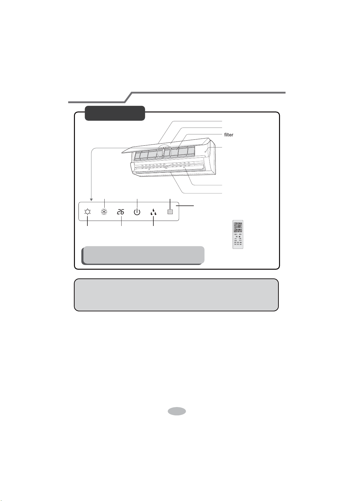
6
(Display content or position may be different from above
graphics, please refer to actual products)
Parts Name
Indoor Unit
air inlet
panel
aux.button
horizontal louver
air outlet
heating
indicator
temp.
indicator
cooling
indicator
power
indicator
receiver
window
drying
indicator
display
remote controller
NOTICE:
Actual product may be different from above graphics, please refer to actual
products.
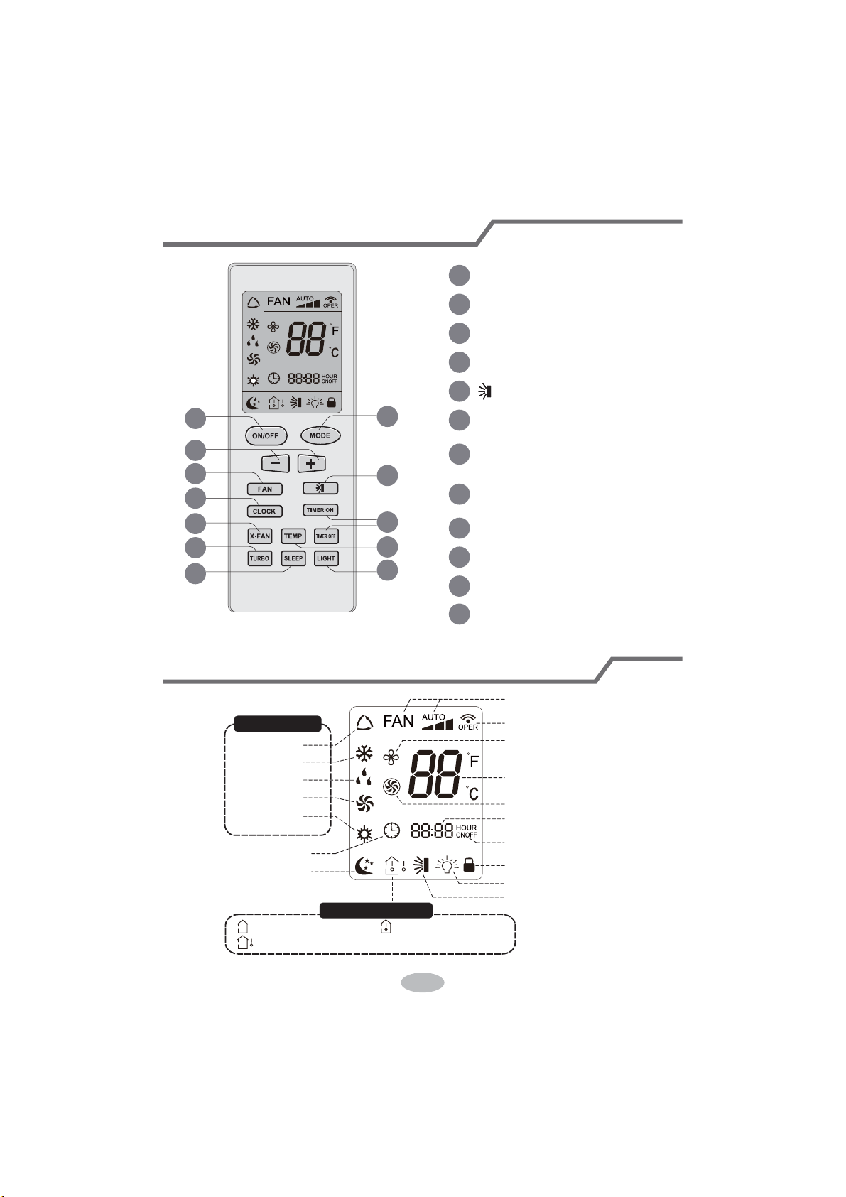
7
Buttons on remote controller
Introduction for icons on display screen
1
2
5
7
9
11
10
12
8
6
4
3
1
2
3
4
5
6
7
8
9
10
11
12
ON/OFF button
MODE button
EXWWRQ
)$1EXWWRQ
button
;)$1EXWWRQ
1RWH;)$1LVWKHVDPHZLWK%/2:
TEMP button
TURBO button
LIGHT button
SLEEP button
TIMER ON/TIMER OFF
button
CLOCK button
Send signal
Turbo mode
Set temperature
Set time
TIMER ON / TIMER OFF
Child lock
Up & down swing
Set fan speed
;IDQPRGH
Light
Temp. display type
: Set temp.
: Outdoor ambient temp.
: Indoor ambient temp.
Sleep mode
Clock
Heat mode
Fan mode
Dry mode
Cool mode
$XWRPRGH
Operation mode
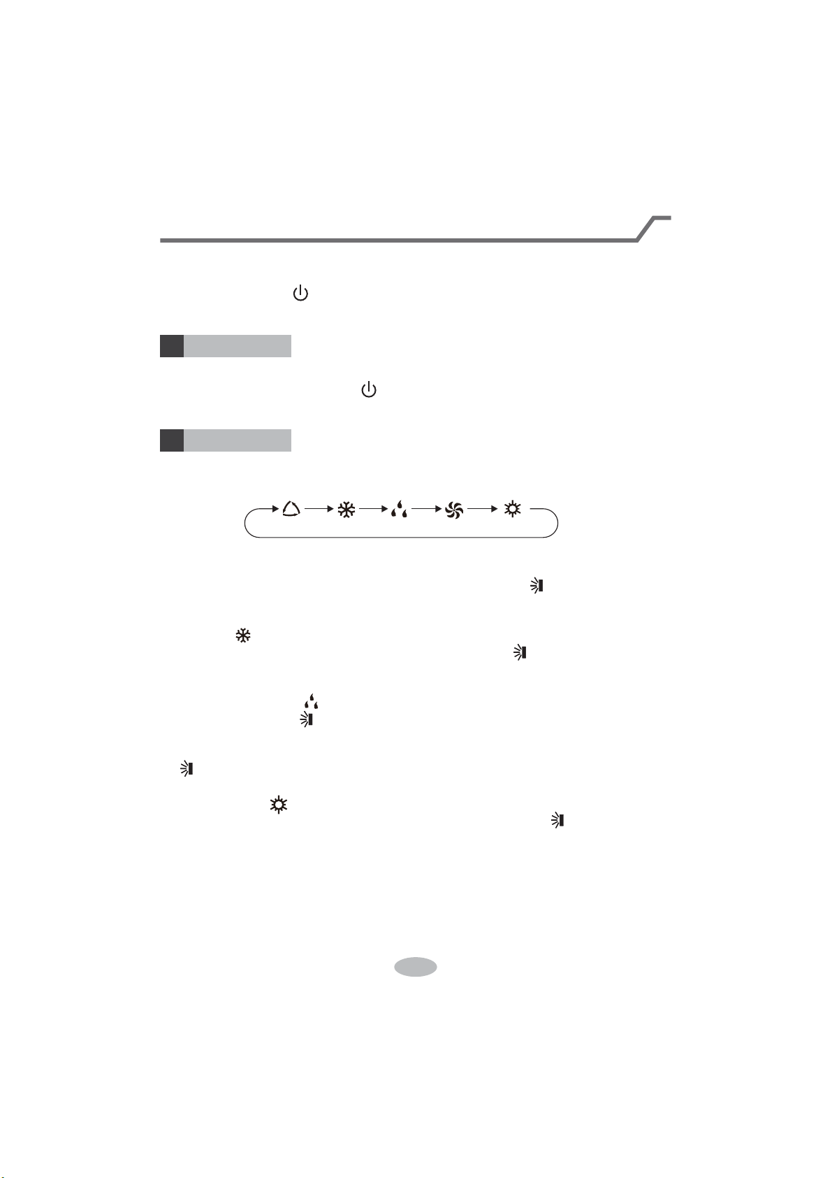
8
Ɣ:KHQVHOHFWLQJDXWRPRGHDLUFRQGLWLRQHUZLOORSHUDWHDXWRPDWLFDOO\DFFRUGLQJ
WRH[IDFWRU\VHWWLQJ6HWWHPSHUDWXUHFDQ¶WEHDGMXVWHGDQGZLOOQRWEHGLVSOD\HG
DVZHOO3UHVV)$1EXWWRQFDQDGMXVWIDQVSHHG3UHVVEXWWRQFDQDGMXVW
fan blowing angle.
Ɣ$IWHUVHOHFWLQJFRROPRGHDLUFRQGLWLRQHUZLOORSHUDWHXQGHUFRROPRGH&RRO
LQGLFDWRURQLQGRRUXQLWLV213UHVVRUEXWWRQWRDGMXVWVHWWHPSH
UDWXUH3UHVV)$1EXWWRQWRDGMXVWIDQVSHHG3UHVVEXWWRQWRDGMXVWIDQ
blowing angle.
Ɣ:KHQVHOHFWLQJGU\PRGHWKHDLUFRQGLWLRQHURSHUDWHVDWORZVSHHGXQGHUGU\
PRGH'U\LQGLFDWRURQLQGRRUXQLWLV218QGHUGU\PRGHIDQVSHHGFDQ¶W
be adjusted. Press " " button to adjust fan blowing angle.
Ɣ:KHQVHOHFWLQJIDQPRGHWKHDLUFRQGLWLRQHUZLOORQO\EORZIDQQRFRROLQJDQG
QRKHDWLQJ$OOLQGLFDWRUVDUH2))3UHVV)$1EXWWRQWRDGMXVWIDQVSHHG3UHVV
" " button to adjust fan blowing angle.
Ɣ:KHQVHOHFWLQJKHDWLQJPRGHWKHDLUFRQGLWLRQHURSHUDWHVXQGHUKHDWPRGH
+HDWLQGLFDWRURQLQGRRUXQLWLV213UHVVRUEXWWRQWRDGMXVWVHW
WHPSHUDWXUH3UHVV)$1EXWWRQWRDGMXVWIDQVSHHG3UHVVEXWWRQWRDGMXVW
IDQEORZLQJDQJOH&RROLQJRQO\XQLWZRQ¶WUHFHLYHKHDWLQJPRGHVLJQDO,IVHWWLQJ
KHDWPRGHZLWKUHPRWHFRQWUROOHUSUHVV212))EXWWRQFDQ¶WVWDUWXSWKHXQLW
Note:
Ɣ)RUSUHYHQWLQJFROGDLUDIWHUVWDUWLQJXSKHDWLQJPRGHLQGRRUXQLWZLOOGHOD\a
minutes to blow air (actual delay time is depend on indoor ambient temperature).
Ɣ6HWWHPSHUDWXUHUDQJHIURPUHPRWHFRQWUROOHUa
ć
; Fan speed: auto, low
speed, medium speed, high speed.
Introduction for buttons on remote controller
Note:
Ɣ$IWHUSXWWLQJWKURXJKWKHSRZHUWKHDLUFRQGLWLRQHUZLOOJLYHRXWDVRXQG
2SHUDWLRQLQGLFWRULV21UHGLQGLFDWRU$IWHUWKDW\RXFDQRSHUDWHWKHDLU
conditioner by using remote controller.
ON/OFF button
MODE button
1
2
3UHVVWKLVEXWWRQFDQWXUQRQRUWXUQRIIWKHDLUFRQGLWLRQHU$IWHUWXUQLQJRQWKHDLU
FRQGLWLRQHURSHUDWLRQLQGLFDWRURQLQGRRUXQLW¶VGLVSOD\LV21JUHHQLQGLFDWRU
The colour is different for different models), and indoor unit will give out a sound.
Press this button to select your required operation mode.
$872COOL )$1DRY +($7
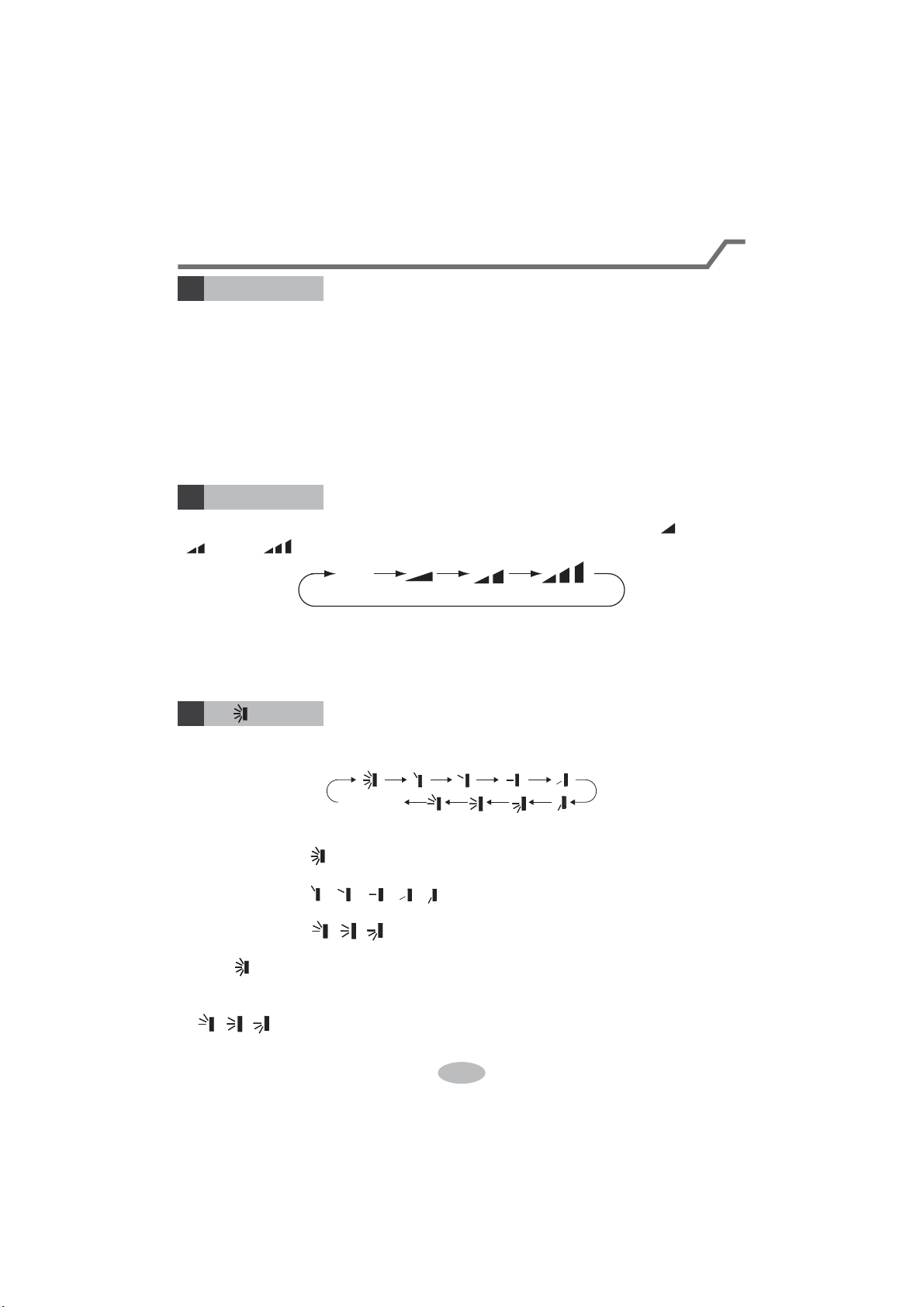
9
Introduction for buttons on remote controller
)$1EXWWRQ
4
3UHVVLQJWKLVEXWWRQFDQVHWIDQVSHHGFLUFXODUO\DVDXWR$872ORZPHGLXP
( ), high( ).
Auto
Note:
Ɣ8QGHU$872VSHHGDLUFRQGLWLRQHUZLOOVHOHFWSURSHUIDQVSHHGDXWRPDWLFDOO\
DFFRUGLQJWRH[IDFWRU\VHWWLQJ
Ɣ)DQVSHHGXQGHUGU\PRGHLVORZVSHHG
5
Press this button can select up&down swing angle. Fan blow angle can be selected
circularly as below:
Ɣ:KHQVHOHFWLQJDLUFRQGLWLRQHULVEORZLQJIDQDXWRPDWLFDOO\+RUL]RQWDO
louver will automatically swing up & down at maximum angle.
Ɣ:KHQVHOHFWLQJ
ǃǃǃǃ
DLUFRQGLWLRQHULVEORZLQJIDQDW¿[HG
SRVLWLRQ+RUL]RQWDOORXYHUZLOOVWRSDWWKH¿[HGSRVLWLRQ
Ɣ:KHQVHOHFWLQJ
ǃǃ
DLUFRQGLWLRQHULVEORZLQJIDQDW¿[HGDQJOH
+RUL]RQWDOORXYHUZLOOVHQGDLUDWWKH¿[HGDQJOH
Ɣ+ROGEXWWRQDERYHVWRVHW\RXUUHTXLUHGVZLQJDQJOH:KHQUHDFKLQJ\RXU
required angle, release the button.
Note:
Ɣ
ǃǃ
" may not be available. When air conditioner receives this signal, the
air conditioner will blow fan automatically.
button
no display
KRUL]RQWDOORXYHUVVWRSV
at current position)
EXWWRQ
3
Ɣ3UHVVRUEXWWRQRQFHLQFUHDVHRUGHFUHDVHVHWWHPSHUDWXUH
ć
.
+ROGLQJRUEXWWRQVODWHUVHWWHPSHUDWXUHRQUHPRWHFRQWUROOHUZLOO
FKDQJHTXLFNO\2QUHOHDVLQJEXWWRQDIWHUVHWWLQJLV¿QLVKHGWHPSHUDWXUHLQGLFD
WRURQLQGRRUXQLWZLOOFKDQJHDFFRUGLQJO\7HPSHUDWXUHFDQ¶WEHDGMXVWHGXQGHU
auto mode)
Ɣ:KHQVHWWLQJ7,0(5217,0(52))RU&/2&.SUHVVRUEXWWRQWR
adjust time. (Refer to CLOCK, TIMER ON, TIMER OFF buttons) When setting
7,0(5217,0(52))RU&/2&.SUHVVRUEXWWRQWRDGMXVWWLPH5HIHU
to CLOCK, TIMER ON, TIMER OFF buttons)
10
Press this button to set clock time. " " icon on remote controller will blink. Press
RUEXWWRQZLWKLQVWRVHWFORFNWLPH(DFKSUHVVLQJRIRUEXWWRQFORFN
WLPHZLOOLQFUHDVHRUGHFUHDVHPLQXWH,IKROGRUEXWWRQVODWHUWLPHZLOO
change quickly. Release this button when reaching your required time. Press
&/2&.EXWWRQWRFRQ¿UPWKHWLPHLFRQVWRSVEOLQNLQJ
Note:
Ɣ&ORFNWLPHDGRSWVKRXUPRGH
Ɣ7KHLQWHUYDOEHWZHHQWZRRSHUDWLRQFDQ¶WH[FHHGVV2WKHUZLVHUHPRWHFRQWUR
ller will quit setting status. Operation for TIMER ON/TIMER OFF is the same.
CLOCK button
6
Introduction for buttons on remote controller
TIMER ON / TIMER OFF button
7
Ɣ7,0(521EXWWRQ
7,0(521EXWWRQFDQVHWWKHWLPHIRUWLPHURQ$IWHUSUHVVLQJWKLVEXWWRQ
LFRQGLVDSSHDUVDQGWKHZRUG21RQUHPRWHFRQWUROOHUEOLQNV3UHVVRU
EXWWRQWRDGMXVW7,0(521VHWWLQJ$IWHUHDFKSUHVVLQJRUEXWWRQ7,0(5
21VHWWLQJZLOOLQFUHDVHRUGHFUHDVHPLQ+ROGRUEXWWRQVODWHUWKH
time will change quickly until reaching your required time.
3UHVV7,0(521WRFRQ¿UPLW7KHZRUG21ZLOOVWRSEOLQNLQJLFRQ
resumes displaying. Cancel TIMER ON: Under the condition that TIMER ON is
started up, press "TIMER ON" button to cancel it.
Ɣ7,0(52))EXWWRQ
7,0(52))EXWWRQFDQVHWWKHWLPHIRUWLPHURII$IWHUSUHVVLQJWKLVEXWWRQ
LFRQGLVDSSHDUVDQGWKHZRUG2))RQUHPRWHFRQWUROOHUEOLQNV3UHVVRU
EXWWRQWRDGMXVW7,0(52))VHWWLQJ$IWHUHDFKSUHVVLQJRUEXWWRQ7,0(5
2))VHWWLQJZLOOLQFUHDVHRUGHFUHDVHPLQ+ROGRUEXWWRQVODWHUWKH
time will change quickly until reaching your required time.
Press "TIMER OFF" word "OFF" will stop blinking. " " icon resumes displaying.
Cancel TIMER OFF. Under the condition that TIMER OFF is started up, press
"TIMER OFF" button to cancel it.
Note:
Ɣ8QGHURQDQGRIIVWDWXV\RXFDQVHW7,0(52))RU7,0(521VLPXOWDQHRXVO\
Ɣ%HIRUHVHWWLQJ7,0(521RU7,0(52))SOHDVHDGMXVWWKHFORFNWLPH
Ɣ$IWHUVWDUWLQJXS7,0(521RU7,0(52))VHWWKHFRQVWDQWFLUFXODWLQJYDOLG
$IWHUWKDWDLUFRQGLWLRQHUZLOOEHWXUQHGRQRUWXUQHGRIIDFFRUGLQJWRVHWWLQJWLPH
212))EXWWRQKDVQRHIIHFWRQVHWWLQJ,I\RXGRQ¶WQHHGWKLVIXQFWLRQSOHDVH
use remote controller to cancel it.
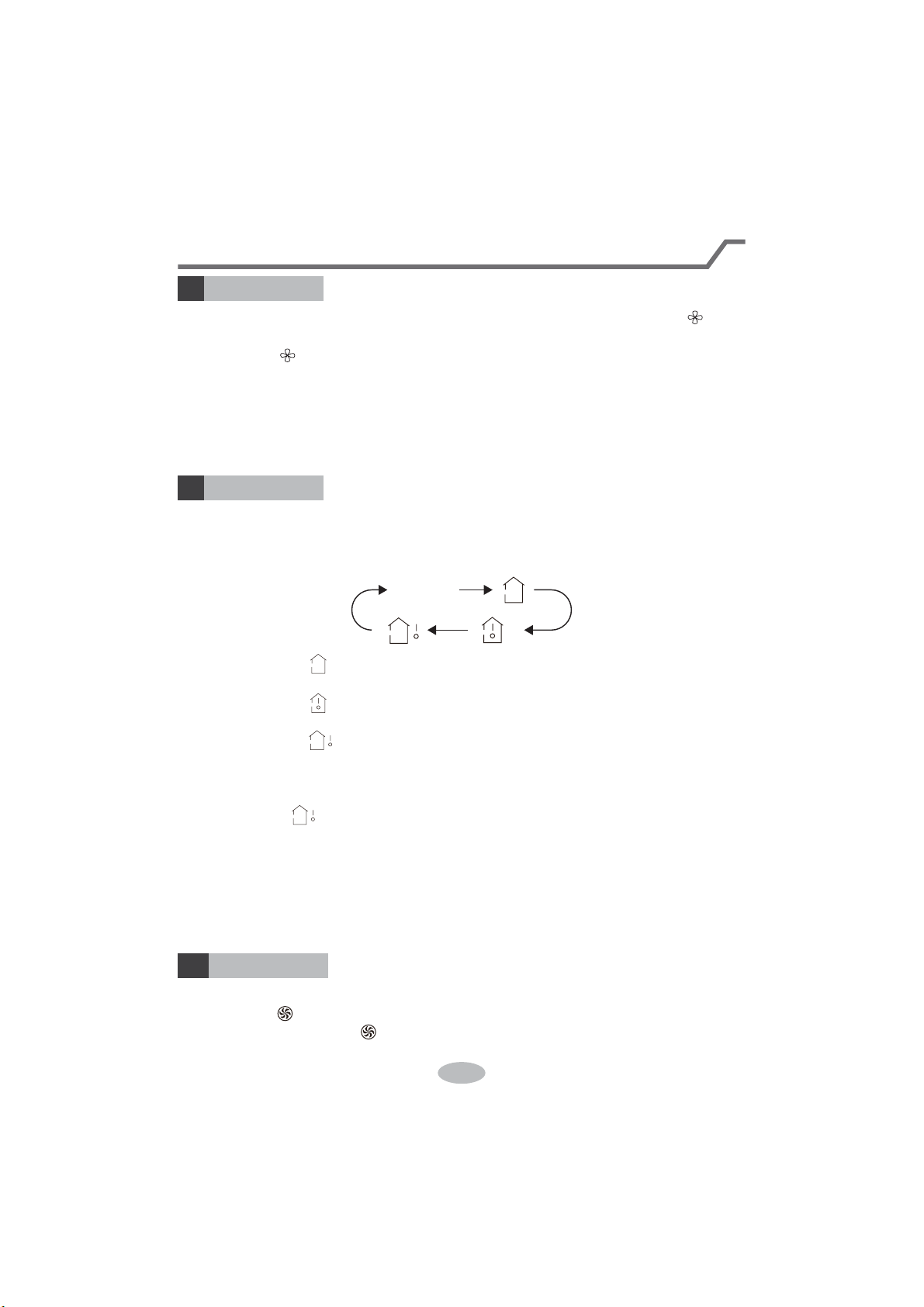
11
TEMP button
9
Introduction for buttons on remote controller
%\SUHVVLQJWKLVEXWWRQ\RXFDQVHHLQGRRUVHWWHPSHUDWXUHLQGRRUDPELHQWWHPS
HUDWXUHRURXWGRRUDPELHQWWHPSHUDWXUHRQLQGRRUXQLW¶VGLVSOD\7KHVHWWLQJRQ
remote controlleris selected circularly as below:
no display
Ɣ:KHQVHOHFWLQJRUQRGLVSOD\ZLWKUHPRWHFRQWUROOHUWHPSHUDWXUHLQGLFDWRU
on indoor unit displays set temperature.
Ɣ:KHQVHOHFWLQJZLWKUHPRWHFRQWUROOHUWHPSHUDWXUHLQGLFDWRURQLQGRRUXQLW
displays indoor ambient temperature.
Ɣ:KHQVHOHFWLQJZLWKUHPRWHFRQWUROOHUWHPSHUDWXUHLQGLFDWRURQLQGRRUXQLW
displays outdoor ambient temperature.
Note:
Ɣ
2XWGRRUWHPSHUDWXUHGLVSOD\LVQRWDYDLODEOHIRUVRPHPRGHOV$WWKDWWLPHLQGRRU
unit receives " " signal, while it displays indoor set temperature.
Ɣ,W¶VGHIDXOWHGWRGLVSOD\VHWWHPSHUDWXUHZKHQWXUQLQJRQWKHXQLW7KHUHLVQR
display in the remote controller.
Ɣ2QO\IRUWKHPRGHOVZKRVHLQGRRUXQLWKDVGXDOGLVSOD\
Ɣ:KHQVHOHFWLQJGLVSOD\LQJRILQGRRURURXWGRRUDPELHQWWHPSHUDWXUHLQGRRU
temperature indicator displays corresponding temperature and automatically turn
WRGLVSOD\VHWWHPSHUDWXUHDIWHUWKUHHRU¿YHVHFRQGV
;)$1EXWWRQ
8
3UHVVWKLVEXWWRQXQGHUFRRODQGGU\PRGHWRVWDUWXS[IDQIXQFWLRQDQGLFRQ
RQUHPRWHFRQWUROOHUZLOOEHGLVSOD\HG3UHVVWKLVEXWWRQDJDLQWRFDQFHO[IDQ
function, and " " icon will disappear.
Note:
Ɣ:KHQ[IDQIXQFWLRQLVRQLIWKHDLUFRQGLWLRQHULVWXUQHGRIILQGRRUIDQZLOOVWLOO
operate at low speed for a while to blow the residual water inside the air duct.
Ɣ'XULQJ[IDQRSHUDWLRQSUHVV;)$1EXWWRQWRWXUQRII[IDQIXQFWLRQ,QGRRUIDQ
will stop operation immediately.
TURBO button
10
8QGHU&22/RU+($7PRGHSUHVVWKLVEXWWRQWRWXUQWRTXLFN&22/RUTXLFN
+($7PRGHLFRQLVGLVSOD\HGRQUHPRWHFRQWUROOHU3UHVVWKLVEXWWRQDJDLQ
to exit turbo function and " " icon will disappear.
12
Function introduction for combination buttons
Child lock function
3UHVVDQGVLPXOWDQHRXVO\WRWXUQRQRUWXUQRIIFKLOGORFNIXQFWLRQ:KHQ
child lock function is on, " " icon is displayed on remote controller. If you operate
the remote controller, the " " icon will blink three times without sending signal to
the unit.
Temperature display switchover function
8QGHU2))VWDWXVSUHVVDQG02'(EXWWRQVVLPXOWDQHRXVO\WRVZLWFKWHPS
erature display between
ć
and
.
Introduction for buttons on remote controller
Press this button to turn off display light on indoor unit. " " icon on remote
controller disappears. Press this button again to turn on display light. " " icon is
displayed.
8QGHU&22/+($7RU'5<PRGHSUHVVWKLVEXWWRQWRVWDUWXSVOHHSIXQFWLRQ
" " icon is displayed on remote controller. Press this button again to cancel sleep
function and " " icon will disappear.
SLEEP button
LIGHT button
11
12
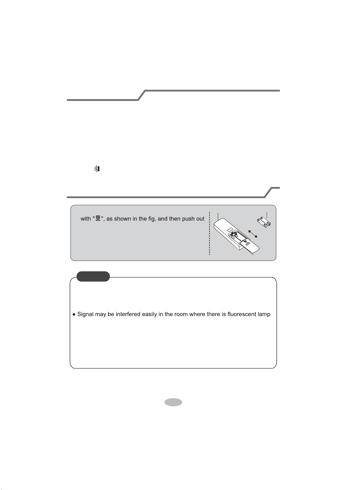
13
1.
After putting through the power, press "ON/OFF" button on remote controller to
turn on the air conditioner.
2.
Press "MODE" button to select your required mode: AUTO, COOL, DRY, FAN,
HEAT.
3.
Press "+" or "-" button to set your required temperature. (Temperature can’t be
adjusted under auto mode).
4.
Press "FAN" button to set your required fan speed: auto, low, medium and high
speed.
5.
Press " " button to select fan blowing angle.
Operation guide
Replacement of batteries in remote controller
1. Press the back side of remote controller marked
the cover of battery box along the arrow direction.
2. Replace two 7# (AAA 1.5V) dry batteries, and
make sure the position of "+" polar and "-" polar
are correct.
3. Reinstall the cover of battery box.
signal sender battery
Cover of battery box
remove
reinstall
Ɣ'XULQJRSHUDWLRQSRLQWWKHUHPRWHFRQWUROVLJQDOVHQGHUDWWKHUHFHLYLQJ
window on indoor unit.
ƔThe distance between signal sender and receiving window should be no
more than 8m, and there should be no obstacles between them.
or wireless telephone; remote controller should be close to indoor unit during
operation.
Ɣ5HSODFHQHZEDWWHULHVRIWKHVDPHPRGHOZKHQUHSODFHPHQWLVUHTXLUHG
Ɣ:KHQ\RXGRQ¶WXVHUHPRWHFRQWUROOHUIRUDORQJWLPHSOHDVHWDNHRXWWKH
batteries.
Ɣ,IWKHGLVSOD\RQUHPRWHFRQWUROOHULVIX]]\RUWKHUH’s no display, please
replace batteries.
NOTICE
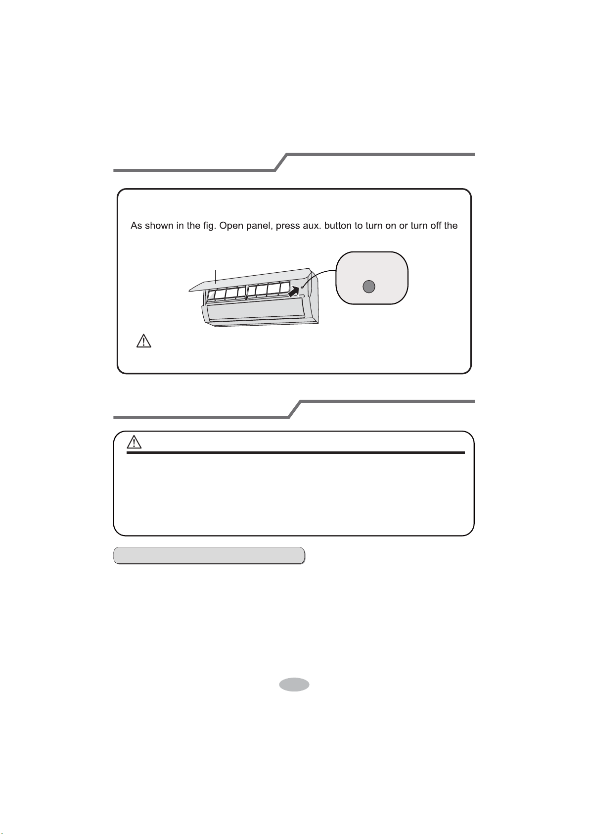
14
Emergency operation
If remote controller is lost or damaged, please use auxiliary button to turn
on or turn off the air conditioner. The operation in details are as below:
air conditioner. When the air conditioner is turned on, it will operate under
auto mode.
aux. button
panel
Clean and Maintenance
Clean surface of indoor unit
When the surface of indoor unit is dirty, it is recommended to use a soft dry cloth
or wet cloth to wipe it.
ŶTurn off the air conditioner and disconnect the power before cleaning the air
conditioner to avoid electric shock.
Ŷ'RQRWZDVKWKHDLUFRQGLWLRQHUZLWKZDWHUWRDYRLGHOHFWULFVKRFN
Ŷ'RQRWXVHYRODWLOHOLTXLGWRFOHDQWKHDLUFRQGLWLRQHr.
WARNING
NOTICE:
Ɣ'RQRWUHPRYHWKHSDQHOZKHQFOHDQLQJLW
WARNING:
Use insulated object to press the auto button
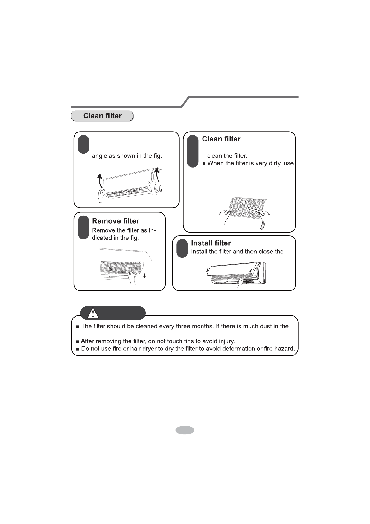
15
Clean and Maintenance
1
2
3
4
Open panel
Pull out the panel to a certain Ɣ8VHGXVWFDWFKHURUZDWHUWR
WKHZDWHUEHORZ
ć
) to clean
LWDQGWKHQSXWLWLQDVKDG\
DQGFRROSODFHWRGU\.
panel cover tightl\.
RSHUDWLRQHQYLURQPHQWFOHDQIUHTXHQF\FDQEHLQFUHDVHG
WARNING
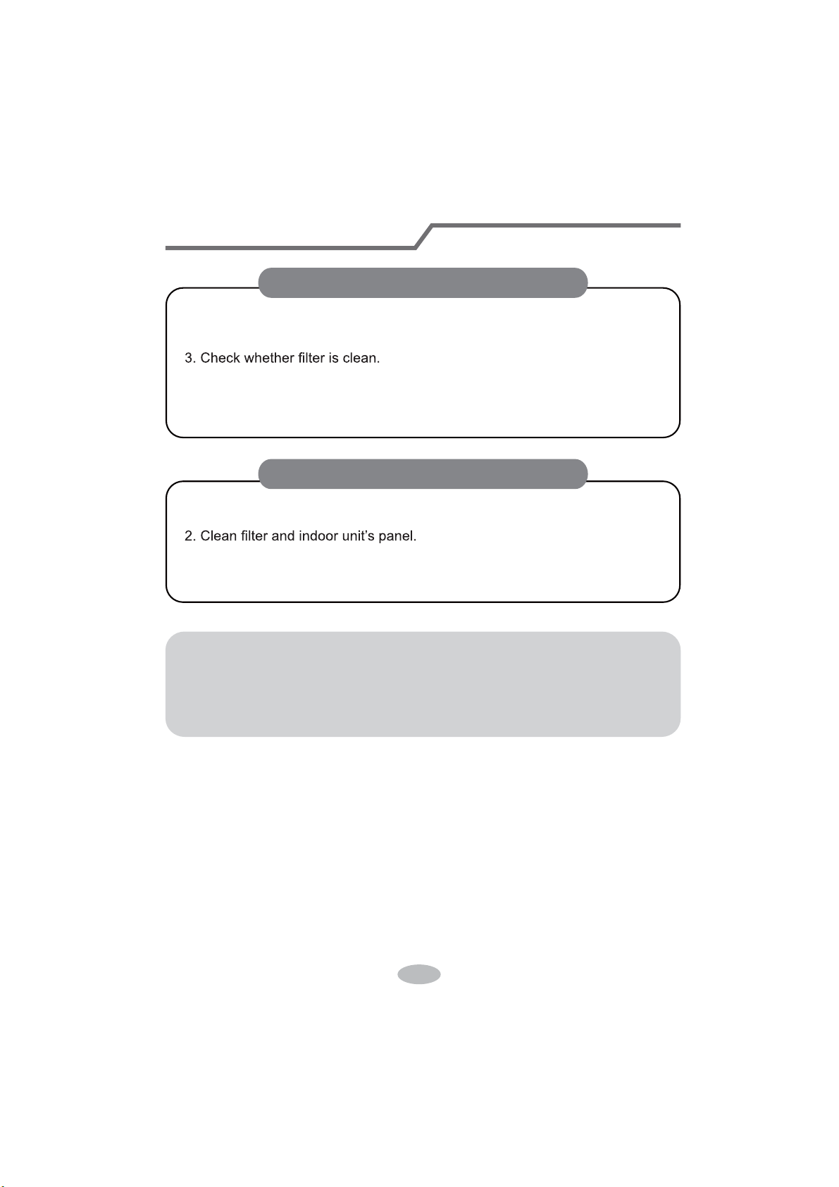
16
Clean and maintenance
1. Check whether air inlets and air outlets are blocked.
2. Check whether circuit break, plug and socket are in good condition.
4. Check whether mounting bracket for outdoor unit is damaged or corroded.
If yes, please contact dealer.
5. Check whether drainage pipe is damaged.
1. Disconnect power supply.
3. Check whether mounting bracket for outdoor unit is damaged or corroded.
If yes, please contact dealer.
Notice for recovery
1. Many packing materials are recyclable materials.
Please dispose them in appropriate recycling unit.
2. If you want to dispose the air conditioner, please contact local dealer or
consultant service center for the correct disposal method.
NOTICE: Checking before use-season
NOTICE: Checking after use-season
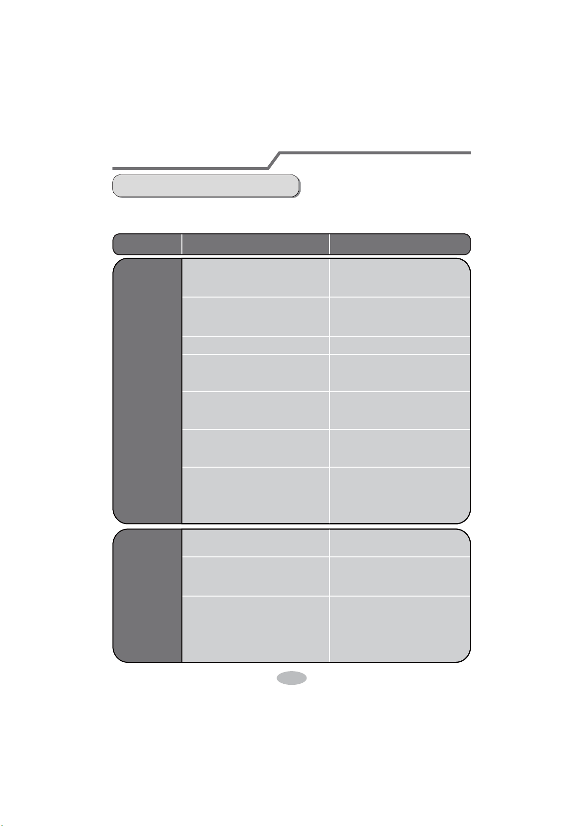
17
Malfunction analysis
General phenomenon analysis
Please check below items before asking for maintenance. If the malfunction still
FDQ¶WEHHOLPLQDWHGSOHDVHFRQWDFWORFDOGHDOHURUTXDOL¿HGSURIHVVLRQDOV
Phenomenon Check items Solution
Indoor unit
can’t receive
remote
controller’s
signal or
remote
controller
has no
action.
Ɣ:KHWKHULWVLQWHUIHUHGVHYHUHO\
(such as static electricity, stable
voltage)?
Ɣ:KHWKHUUHPRWHFRQWUROOHULV
within the signal receiving
range?
Ɣ:KHWKHUWKHUHDUHREVWDFOHV"
Ɣ:KHWKHUUHPRWHFRQWUROOHULV
pointing at the receiving
window?
Ɣ,VVHQVLWLYLW\RIUHPRWHFRQWUR
OOHUORZIX]]\GLVSOD\DQGQR
display?
Ɣ1RGLVSOD\ZKHQRSHUDWLQJ
remote controller?
Ɣ)OXRUHVFHQWODPSLQURRP"
Ɣ3XOORXWWKHSOXJ5HLQVHUW
the plug after about 3min, and
then turn on the unit again.
Ɣ6LJQDOUHFHLYLQJUDQJHLVP
Ɣ5HPRYHREVWDFOHV
Ɣ
Select proper angle and point
the remote controller at the re-
ceiving window on indoor unit.
Ɣ&KHFNWKHEDWWHULHV,IWKH
power of batteries is too low,
please replace them.
Ɣ7DNHWKHUHPRWHFRQWUROOHU
close to indoor unit.
Ɣ7XUQRIIWKHÀXRUHVHQWODPS
and then try it again.
Ɣ&KHFNZKHWKHUUHPRWHFRQW
roller appears to be damaged.
If yes, replace it.
No air
emitted
from
indoor
unit
Ɣ$LULQOHWRUDLURXWOHWRILQGRRU
unit is blocked?
Ɣ(OLPLQDWHREVWDFOHV
Ɣ8QGHUKHDWLQJPRGHLQGRRU
temperature is reached to set
temperature?
Ɣ$IWHUUHDFKLQJWRVHWWHPSHU
ature, indoor unit will stop bl-
owing out air.
Ɣ+HDWLQJPRGHLVWXUQHGRQMXVW
now?
Ɣ,QRUGHUWRSUHYHQWEORZLQJ
out cold air, indoor unit will be
started after delaying for sev-
eral minutes, which is a nor-
mal phenomenon.
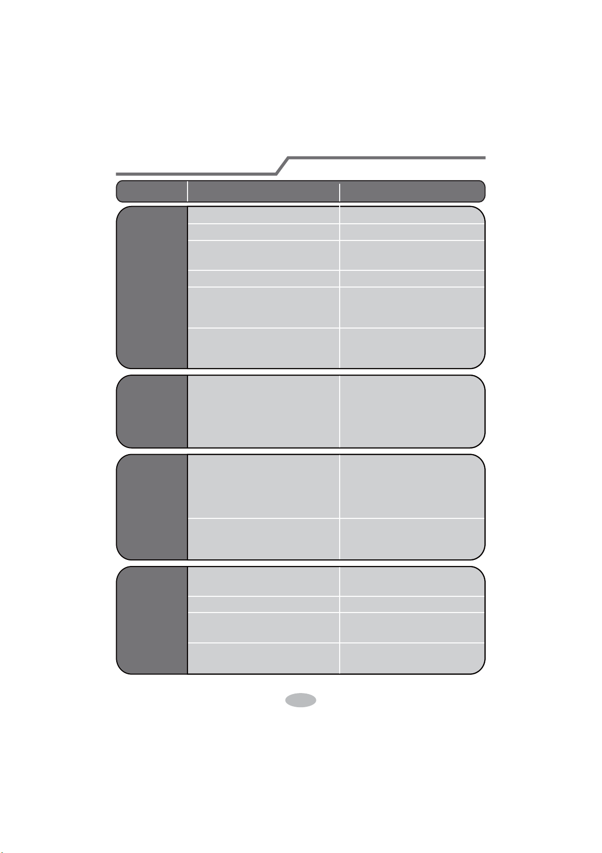
18
Malfunction analysis
Ɣ3RZHUIDLOXUH"
Ɣ,VSOXJORRVH"
ƔCircuit break trips off or fuse is
burnt out?
Ɣ:LULQJKDVPDOIXQFWLRQ"
Ɣ8QLWKDVUHVWDUWHGLPPHGLDWHO\
after stopping operation?
Ɣ:KHWKHUWKHIXQFWLRQVHWWLQJ
for remote controller is
correct?
Ɣ5HVHWWKHIXQFWLRQ
Ɣ:DLWIRUPLQDQGWKHQWXUQ
on the unit again.
Ɣ$VNSURIHVVLRQDOWRUHSODFHLW
Ɣ$VNSURIHVVLRQDOWRUHSODFH
circuit break or fuse.
Ɣ5HLQVHUWWKHSOXJ
Ɣ:DLWXQWLOSRZHUUHFRYHU\
Air condit-
ioner can’t
operate
Mist is em-
itted from
indoor unit’s
air outlet
Ɣ,QGRRUWHPSHUDWXUHDQGKXP
idity is high?
Ɣ%HFDXVHLQGRRUDLULVFRROHG
rapidly. After a while, indoor
temperature and humidity will
be decrease and mist will
disappear.
Phenomenon Check items Solution
Set temper-
ature can’t
be adjusted
Ɣ8QLWLVRSHUDWLQJXQGHUDXWR
mode?
Ɣ7HPSHUDWXUHFDQ¶WEHDGMX
sted under auto mode.
Please switch the operation
mode if you need to adjust
temperature.
Ɣ<RXUUHTXLUHGWHPSHUDWXUH
exceeds the set temperature
range?
Ɣ6HWWHPSHUDWXUHUDQJH
16
ć
~30
ć
.
Cooling
(heating)
effect is
not good.
Ɣ9ROWDJHLVWRRORZ"
Ɣ:DLWXQWLOWKHYROWDJH
resumes normal.
Ɣ)LOWHULVGLUW\"Ɣ&OHDQWKH¿OWHU
Ɣ6HWWHPSHUDWXUHLVLQSURSHU
range?
Ɣ$GMXVWWHPSHUDWXUHWRSURSHU
range.
Ɣ'RRUDQGZLQGRZDUHRSHQ"Ɣ&ORVHGRRUDQGZLQGRZ
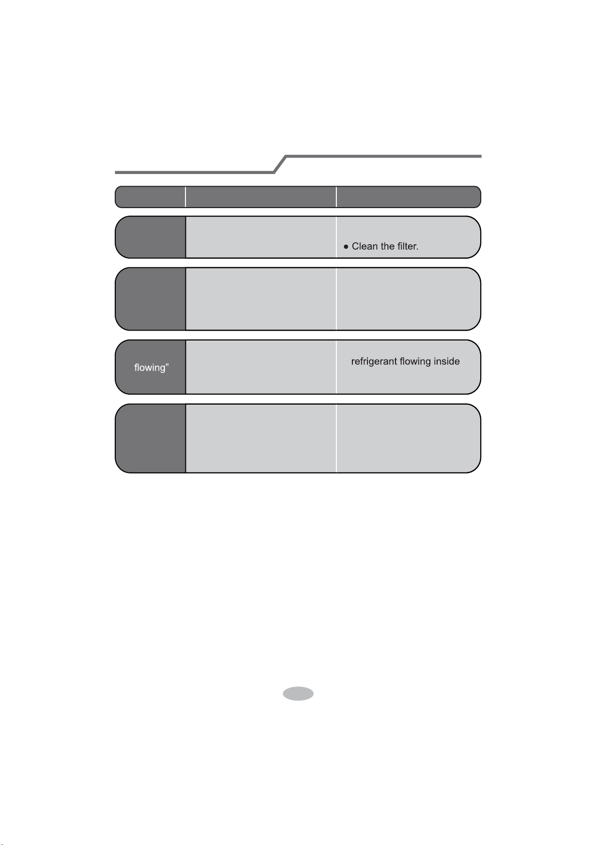
19
Malfunction analysis
Phenomenon Check items Solution
Odours are
emitted
Ɣ:KHWKHUWKHUH’s odour source,
such as furniture and cigarette,
etc.
Ɣ(OLPLQDWHWKHRGRXUVRXUFH
Air conditio-
ner operates
abnormally
Ɣ:KHWKHUWKHUH’s interference,
such as thunder, wireless
devices, etc.
Ɣ'LVFRQQHFWSRZHr, put back
power, and then turn on the
unit again.
“:ater
noise
Ɣ Air conditioner is turned on or
turned off just now?
Ɣ The noise is the sound of
the unit, which is a normal
phenomenon.
Cracking
noise
Ɣ Air conditioner is turned on or
turned off just now?
Ɣ This is the sound of friction
caused by expansion and/or
contraction of panel or other
parts due to the change of
temperature.
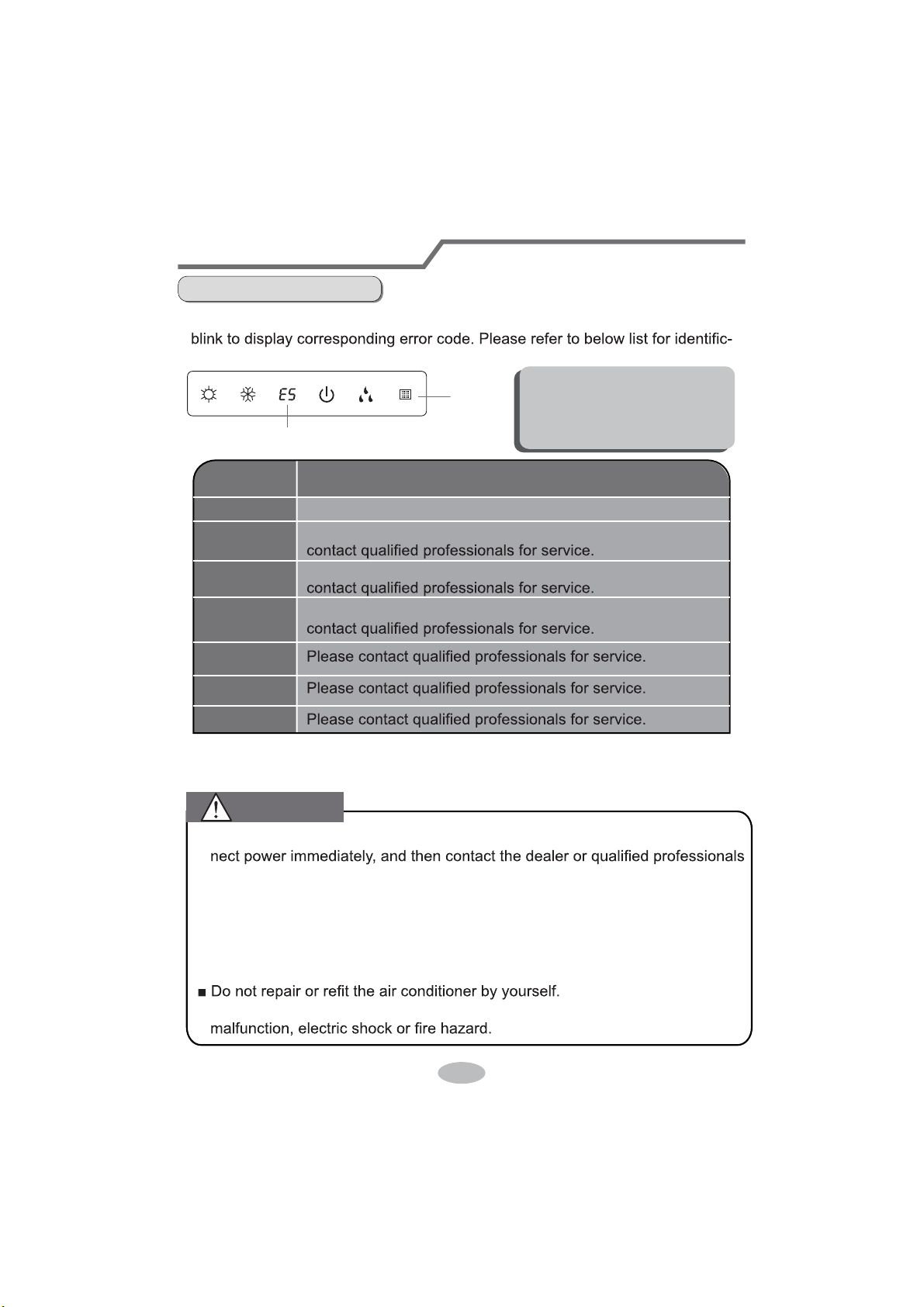
20
Malfunction analysis
Error code
E5
U8
H6
C5
F1
F2
Troubleshooting
It can be eliminated after restarting the unit. If not, please
It can be eliminated after restarting the unit. If not, please
It can be eliminated after restarting the unit. If not, please
Error Code
Ɣ:KHQDLUFRQGLWLRQHUVWDWXVLVDEQRUPDl, temperature indictor on indoor unit will
ation of error code.
Indoor
display
Error code
Above indicator diagram is only
for reference. Please refer to
actual product for the actual
indicator and position.
Means defrosting status. It’s the normal phenomenon.
Note: If there're other error codes, please contact qualified professionals for
service.
Heating indicator
ON 10s OFF 0.5s
Ŷ:KHQEHORZSKHQRPHQRQRFFXUVSOease turn off air conditioner and discon-
for service.
Ɣ3RZHUFRUGLVRYHUKHDWLQJRUGDPDJHG
ƔThere’s abnormal sound during operation.
Ɣ&LUFXLWEUHDNWULSVRff frequently.
ƔAir conditioner gives off burning smell.
Ɣ,QGRRUXQLWLVOHDNLQJ
Ŷ,IWKHDLUFRQGLWLRQHURSHUDWHVXQGHUDbnormal conditions, it may cause
WARNING

21
Installation dimension diagram
At least 250cm
At least 15cm
At least 300cm
6SDFHWRWKHÀRRU
Space to the ceiling
Space to the obstruction
At least 15cm
At least 15cm
Space to the wall
Space to the wall
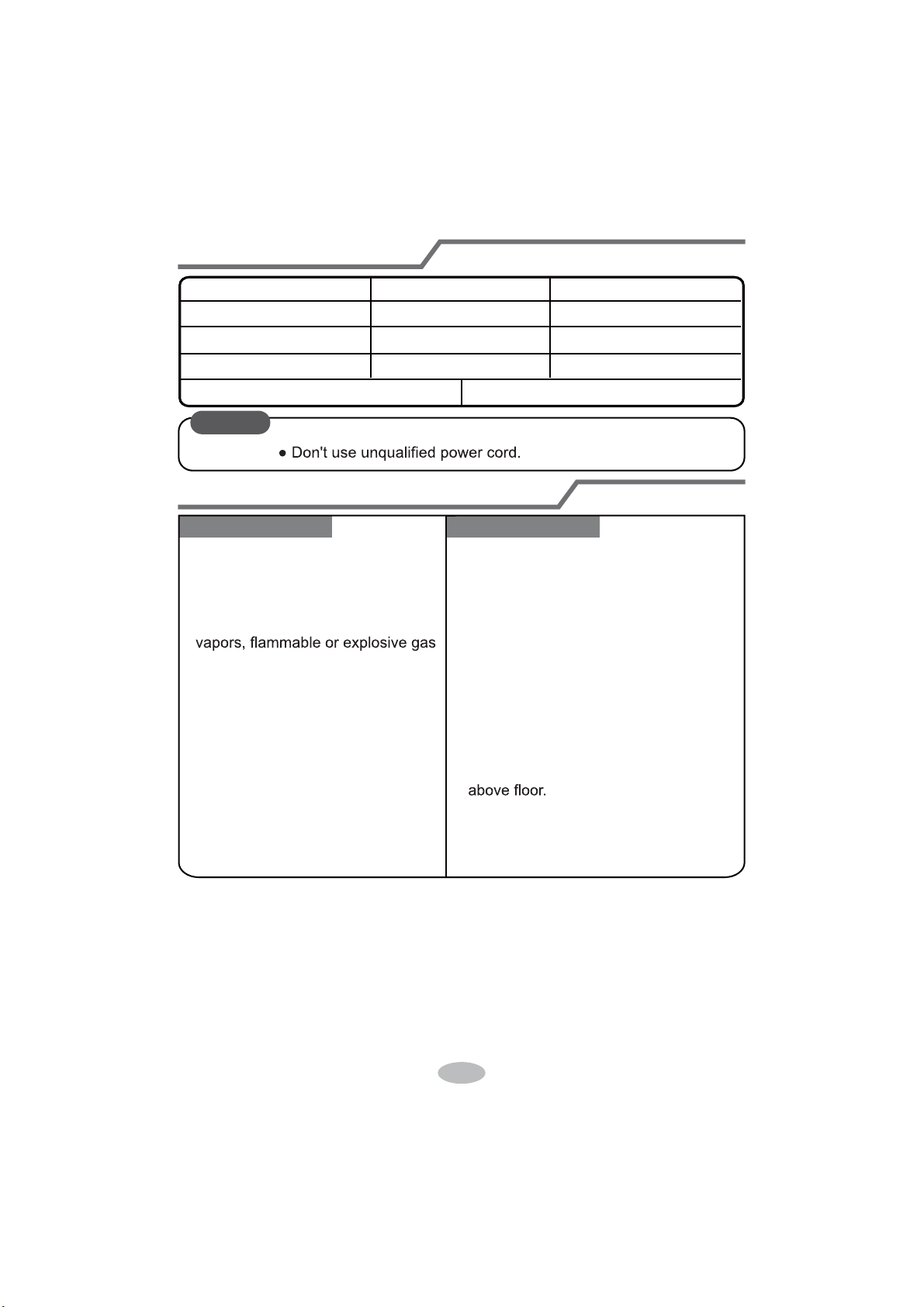
22
Selection of installation location
Basic requirement
Installing the unit in the following pla-
ces maycause malfunction. If it is un-
avoidable, please consult the local
dealer:
1. There should be no obstruction near air
inlet and air outlet.
2. Select a location where the condensat-
ion water can be dispersed easily and
won't affect other people.
3. Select a location which is convenient to
connect the outdoor unit and near the
power socket.
4. Select a location which is out of reach
for children.
5.
The location should be able to withstand
the weight of indoor unit and won't incr-
ease noise and vibration.
6.
The appliance must be installed 2.5m
7. Don't install the indoor unit right above
the electric appliance.
Indoor unit
1.The place with strong heat sources,
,
8. Please try your best to keep way from
fluorescent lamp.
or volatile objects spread in the air.
2.The place with high-frequency
devices (such as welding machine,
medical equipment).
3.The place near coast area.
4.
The place with oil or fumes in the air.
5.The place with sulfureted gas.
6.Other places with special circums-
tances.
7.The appliance shall not be install-
ed in the laundry
Tools for installation
1 Level meter 2 Screw driver 3 Impact drill
4 Drill head 5 Pipe expander 6 Torque wrench
7 Open-end wrench 8 Pipe cutter 9 Leakage detector
10 Vacuum pump 11 Pressure meter 12 Universal meter
13 Inner hexagon spanner 14 Measuring tape
Note:
Ɣ3OHDVHFRQWDFWWKHORFDODJHQWIRULQVWDOODWLRQ
23
Requirements for electric connection
Safety precaution
Grounding requirement
1. Must follow the electric safety regulations when installing the unit.
circuit break.
3. Make sure the power supply matches with the requirement of air conditioner.
Unstable power supply or incorrect wiring or malfunction. Please install proper
power supply cables before using the air conditioner.
4. Properly connect the live wire, neutral wire and grounding wire of power socket.
5. Be sure to cut off the power supply before proceeding any work related to
electricity and safety.
7. If the supply cord is damaged, it must be replaced by the manufacturer, its
8. The temperature of refrigerant circuit will be high, please keep the interconnec-
tion cable away from the copper tube.
grounding with specialized grounding device by a professional. Please make
sure it is always grounded effectively, otherwise it may cause electric shock.
2. The yellow-green wire in air conditioner is grounding wire, which can't be used
for other purposes.
3. The grounding resistance should comply with national electric safety regulations.
4. The appliance must be positioned so that the plug is accessible.
5. An all-pole disconnection switch having a contact separation of at least 3mm in
6. Including an circuit break with suitable capacity, please note the following table.
Circuit break should be included magnet buckle and heating buckle function, it
can protect the circuit-short and overload. (Caution: please do not use the fuse
only for protect the circuit)
9. The appliance shall be installed in accordance with national wiring regulations.
10. Installation must be performed in accordance with the requirement of NEC
and CEC by authorized personnel only.
Air-conditioner
Air switch capacity
18K
24K
20A
25A
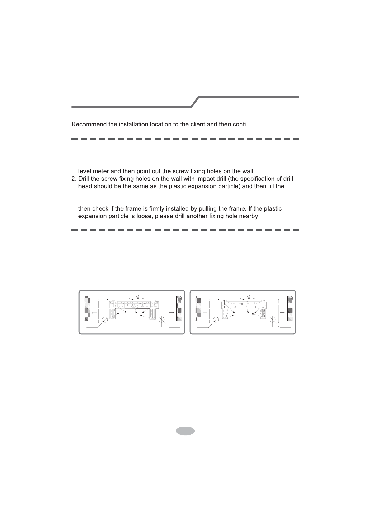
24
Installation of indoor unit
Step one: choosing installation location
Step two: install wall-mounting frame
rm it with the client.
1. Hang the wall-mounting frame on the wall; adjust it in horizontal position with the
plastic expansion particles in the holes.
3. Fix the wall-mounting frame on the wall with tapping screws (ST4.2X25TA) and
.
1. Choose the position of piping hole according to the direction of outlet pipe. The
position of piping hole should be a little lower than the wall-mounted frame,
shown as below.
Step three: open piping hole
2. Open a piping hole with the diameter ofĭRUĭRQWKHVHOHFWHGRXWOHWSLSH
position. In order to drain smoothly, slant the piping hole on the wall slightly
GRZQZDUGWRWKHRXWGRRUVLGHZLWKWKHJUDGLHQWRI
mm
ɎPP
ɎPP
mm51
Wall
Wall
Mark on the middle of it
Gradienter
Left
Right
(Rear piping hole)
(Rear piping hole)
Space
to the
wall
above
Space
to the
wall
above
18K
mm
ɎPP
ɎPP
mm51
Wall
Wall
Mark on the middle of it
Gradienter
Left
Right
(Rear piping hole)
(Rear piping hole)
Space
to the
wall
above
Space
to the
wall
above
24K
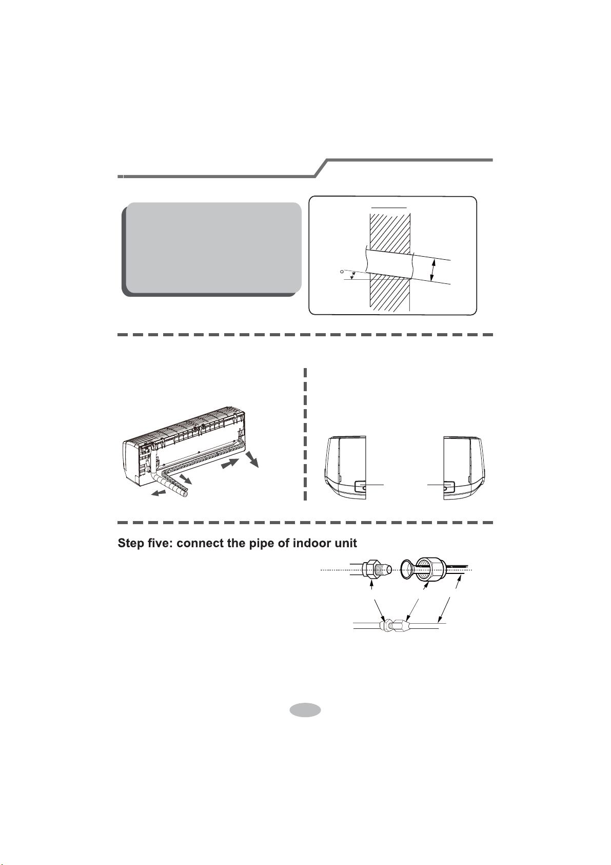
25
1. Aim the pipe joint at the corresponding
bellmouth.
2. Pretightening the union nut with hand.
3. Adjust the torque force by referring to the following sheet. Place the open-end
wrench on the pipe joint and place the torque wrench on the union nut. Tighten
the union nut with torque wrench.
2. When select leading out the pipe
from left or right, please cut off the
corresponding hole on the bottom
case.
cut off
the hole
left right
1. The pipe can be led out in the
direction of right, rear right, left or
rear left.
left
rear left
right
rear right
Step four: outlet pipe
Installation of indoor unit
union nutpipe joint
pipe
Note:
Ɣ3D\DWWHQWLRQWRGXVWSUHYHQWLRQDQG
WDNHUHOHYDQWVDIHW\PHDVXUHVZKHQ
opening the hole.
ƔThe plastic expansion particles are
QRWSURYLGHGDQGVKRXOGEHERXJKW
locally.
Indoor
5-10
outdoor
ĭ
ĭ
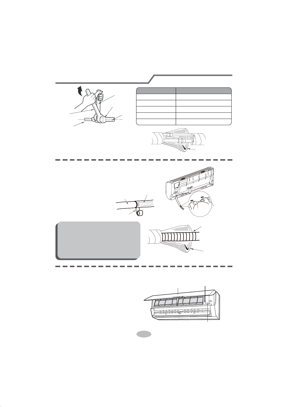
26
nection pipe with insulating pipe, and
insulating pipe
1. Connect the drain hose to the outlet pipe of
outlet
pipe
drain hose
drain hose
tape
outlet pipe
drain hose
insulating pipe
ƔAdd insulating pipe in the indoor
ƔThe plastic expansion particles are
1. Open the panel, remove the screw
on the wiring cover and then take
wiring cover
screw
panel
Step seven: connect wire of indoor unit
4. Wrap the indoor pipe and joint of con-
then wrap it with tape.
Step six: install drain hose
Installation of indoor unit
torque wrench
open-end
wrench
indoor pipe
pipe
union nut
Hex nut diameter Tightening torque (N
.
m)
ĭ
ĭ
ĭ
ĭ
ĭ
30~40
45~55
60~65
70~75
15~20
indoor unit.
2. Bind the joint with tape.
Note:
drain hose in order to prevent
condensation.
not provided.
down the cover.
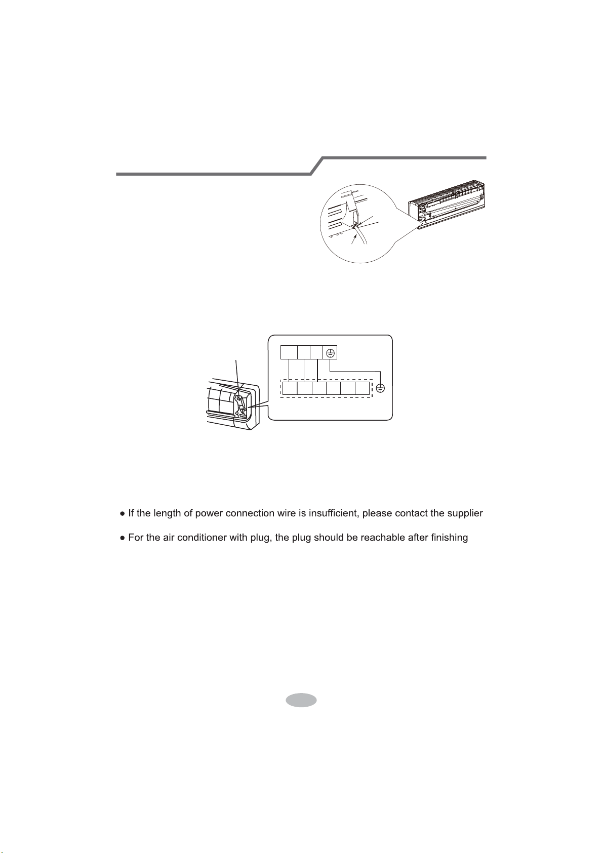
27
4. Put wiring cover back and then tighten the screw.
5. Close the panel.
Installation of indoor unit
Note:
ƔAll wires of indoor unit and outdoor unit should be connected by a professional.
for a new one. Avoid extending the wire by yourself.
installation.
Ɣ)RUWKHDLUFRQGLWLRQHUZLWKRXWSOXJDQcircuit break must be installed in the line.
The air switch should be all-pole parting and the contact parting distance should
be more than 3mm.
3. Remove the wire clip; connect the power connection wire to the wiring terminal
according to the color; tighten the screw and then fix the power connection wire
with wire clip.
power connection
wire
cable-cross
hole
2. Make the power connection wire go
through the cable-cross hole at the back
of indoor unit and then pull it out from
the front side.
Wiring cover
outdoor unit connection
N(1) 2 3
23N(1) L2 GL1
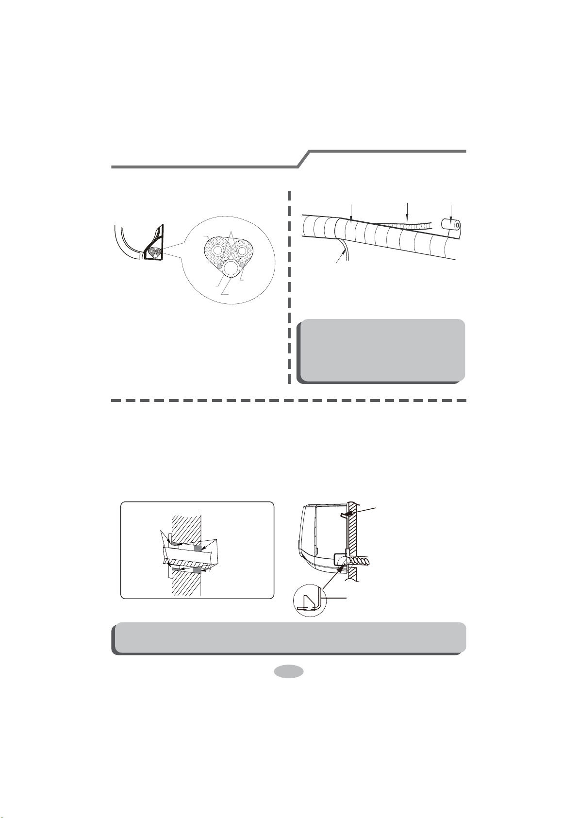
28
Installation of indoor unit
Step eight: bind up pipe
1. Bind up the connection pipe, power
cord and drain hose with the band.
indoor unit
gas
pipe
indoor and
outdoor power cord
liquid pipe
drain hose
band
2. Reserve a certain length of drain
hose and power cord for installation
when binding them. When binding to
a certain degree, separate the indoor
power and then separate the drain
hose.
3. Bind them evenly.
4. The liquid pipe and gas pipe should
be bound separately at the end.
Note:
Ɣ7KHSRZHUFRUGDQGFRQWUROZLUH
FDQWEHFURVVHGRUZLQGLQJ
Ɣ7KHGUDLQKRVHVKRXOGEHERXQG
at the bottom.
drain hose
band
connection pipe
indoor power cord
Step nine: hang the indoor unit
1. Put the bound pipes in the wall pipe and then make them pass through the wall
hole.
2. Hang the indoor unit on the wall-mounting frame.
3. Stuff the gap between pipes and wall hole with sealing gum.
4. Fix the wall pipe.
5. Check if the indoor unit is installed firmly and closed to the wall.
Note:
Ɣ'RQRWEHQGWKHGUDLQKRVHWRRH[FHVVLYHO\LQRUGHUWRSUHYHQWEORFNLQJ
indoor
outdoor
wall pipe
sealing gum
upper hook
lower hook of
wall-mounting frame

29
Check after installation
Test operation
Ɣ&KHFNDFFRUGLQJWRWKHIROORZLQJUHTXLUHPHQWDIWHU¿QLVKLQJLQVWDOODWLRQ
Items to be checked Possible malfunction
+DVWKHXQLWEHHQLQVWDOOHG¿UPO\"The unit may drop, shake or emit noise.
Have you done the refrigerant leakage
test?
,WPD\FDXVHLQVXI¿FLHQWFRROLQJ
(heating) capacity.
,VKHDWLQVXODWLRQRISLSHOLQHVXI¿FLHQW"
It may cause condensation and water
dripping.
Is water drained well?
It may cause condensation and water
dripping.
Is the voltage of power supply accord-
ing to the voltage marked on the
nameplate?
It may cause malfunction or damaging
the parts.
Is electric wiring and pipeline installed
correctly?
It may cause malfunction or damaging
the parts.
Is the unit grounded securely? It may cause electric leakage.
Does the power cord follow the speci-
¿FDWLRQ"
It may cause malfunction or damaging
the parts.
Is there any obstruction in the air inlet
and outlet?
,WPD\FDXVHLQVXI¿FLHQWFRROLQJ
(heating) capacity.
The dust and sundries caused during
installation are removed?
It may cause malfunction or damaging
the parts.
The gas valve and liquid valve of
connection pipe are open completely?
,WPD\FDXVHLQVXI¿FLHQWFRROLQJ
(heating) capacity.
1. Preparation of test operation
Ɣ7KHFOLHQWDSSURYHVWKHDLUFRQGLWLRQHU
Ɣ6SHFLI\WKHLPSRUWDQWQRWHVIRUDLUFRQGLWLRQHUWRWKHFOLHQW
2. Method of test operation
Ɣ3XWWKURXJKWKHSRZHUSUHVV212))EXWWRQRQWKHUHPRWHFRQWUROOHUWRVWDUW
operation.
Ɣ3UHVV02'(EXWWRQWRVHOHFW$872&22/'5<)$1DQG+($7WRFKHFN
whether the operation is normal or not.
Ɣ,IWKHDPELHQWWHPSHUDWXUHLVORZHUWKDQ
ć
, the air conditioner can’t
start cooling.
30
1. Standard length of connection pipe
ƔPPP
4. The additional refrigerant oil and refrigerant charging required after prolonging
connection pipe
Ɣ$IWHUWKHOHQJWKRIFRQQHFWLRQSLSHLVSURORQJHGIRUPDWWKHEDVLVRI
VWDQGDUGOHQJWK\RXVKRXOGDGGPORIUHIULJHUDQWRLOIRUHDFKDGGLWLRQDOP
of connection pipe.
ƔThe calculation Pethod of additional refrigerant charging DPRXnt (on the EDVis
of liquid pipe):
$GGLWLRQDOUHIULJHUDQWFKDUJLQJDPRXQW SURORQJHGOHQJWKRIOLTXLGSLSHî
DGGLWLRQDOUHIULJHUDQWFKDUJLQJDPRXQWSHUPHWHU
Cooling
FDSDFLW\
Cooling
FDSDFLW\
%WXK
:
%WXK
:
%WXK
:
%WXK
:
%WXK
:
%WXK
:
%WXK
:
%WXK
:
%WXK
:
%WXK
:
Max height
difference
Max height
difference
Max length
of connec-
tion pipe
Max length
of connec-
tion pipe
10
3010
3020
20 3010 20
3010 20
2. 0LQOHQJWKRIFRQQHFWLRQSLSHLVP
3. 0D[OHQJWKRIFRQQHFWLRQSLSHDQGPD[KLJKGLfference.
Ɣ%DVLQJRQWKHOHQJWKRIVWDQGDUGSLSHDGGUHIULJHUDQWDFFRUGLQJWRWKH
UHTXLUHPHQWDVVKRZQLQWKHWDEOH7KHDGGLWLRQDOUHIULJHUDQWFKDUJLQJDPRXQW
SHUPHWHULVGLfIHUHQWDFFRUGLQJWRWKHGLDPHWHURIOLTXLGSLSH6HHWKH
IROORZLQJVKHHW
Configuration of connection pipe
31
Additional refrigerant charging amount for R22, R407C, R410A and R134a
Diameter of connection pipe
Liquid pipe(mm) Gas pipe(mm)
ĭ
ĭRUĭ
ĭRUĭ
ĭ
ĭ
ĭ
ĭ
ĭRUĭ
ĭRUĭ
ĭRUĭ
_
_
Cooling only(g/m) Cooling and heating(g/m)
15
15
30
60
250 250
350350
120
120
50
20
Outdoor unit throttle
&RQ¿JXUDWLRQRIFRQQHFWLRQSLSH
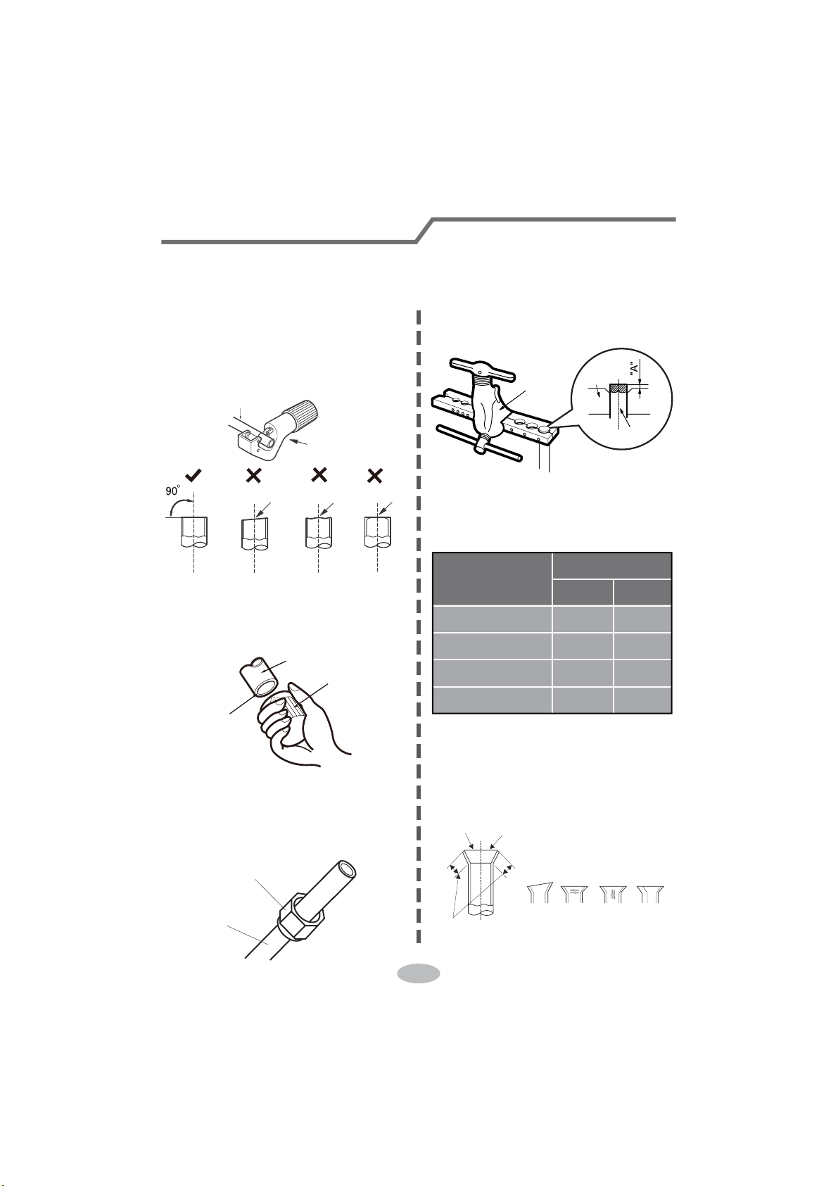
32
Pipe expanding method
Note:
Improper pipe expanding is the main cause of refrigerant leakage. Please expand
the pipe according to the following steps:
A: Cut the pipe
Ɣ&RQ¿UPWKHSLSHOHQJWKDFFRUGLQJWR
the distance of indoor unit and
outdoor unit.
Ɣ&XWWKHUHTXLUHGSLSHZLWKSLSHFXWWHU
pipe
pipe cutter
leaning uneven burr
B: Remove the burrs
Ɣ5HPRYHWKHEXUUVZLWKVKDSHUDQG
prevent the burrs from getting into
the pipe.
downwards
pipe
shaper
C: Put on suitable insulating pipe
D: Put on the union nut
Ɣ5HPRYHWKHXQLRQQXWRQWKHLQGRRU
connection pipe and outdoor valve;
install the union nut on the pipe.
union pipe
pipe
E: Expand the port
Ɣ([SDQGWKHSRUWZLWKH[SDQGHU
Note:
Ɣ$LVGLIIHUHQWDFFRUGLQJWRWKH
diameter, please refer to the sheet
below:
expander
hard
mold
pipe
F: Inspection
Ɣ&KHFNWKHTXDOLW\RIH[SDQGLQJSRUW
If there is any blemish, expand the
port again according to the steps
above.
the length is equal
improper expanding
leaning
damaged
surface
crack uneven
thickness
smooth surface
Outer diameter
(mm)
A(mm)
Max Min
ĭ
ĭ
ĭ
ĭ
1.3 0.7
1.6 1.0
1.8 1.0
2.4 2.2
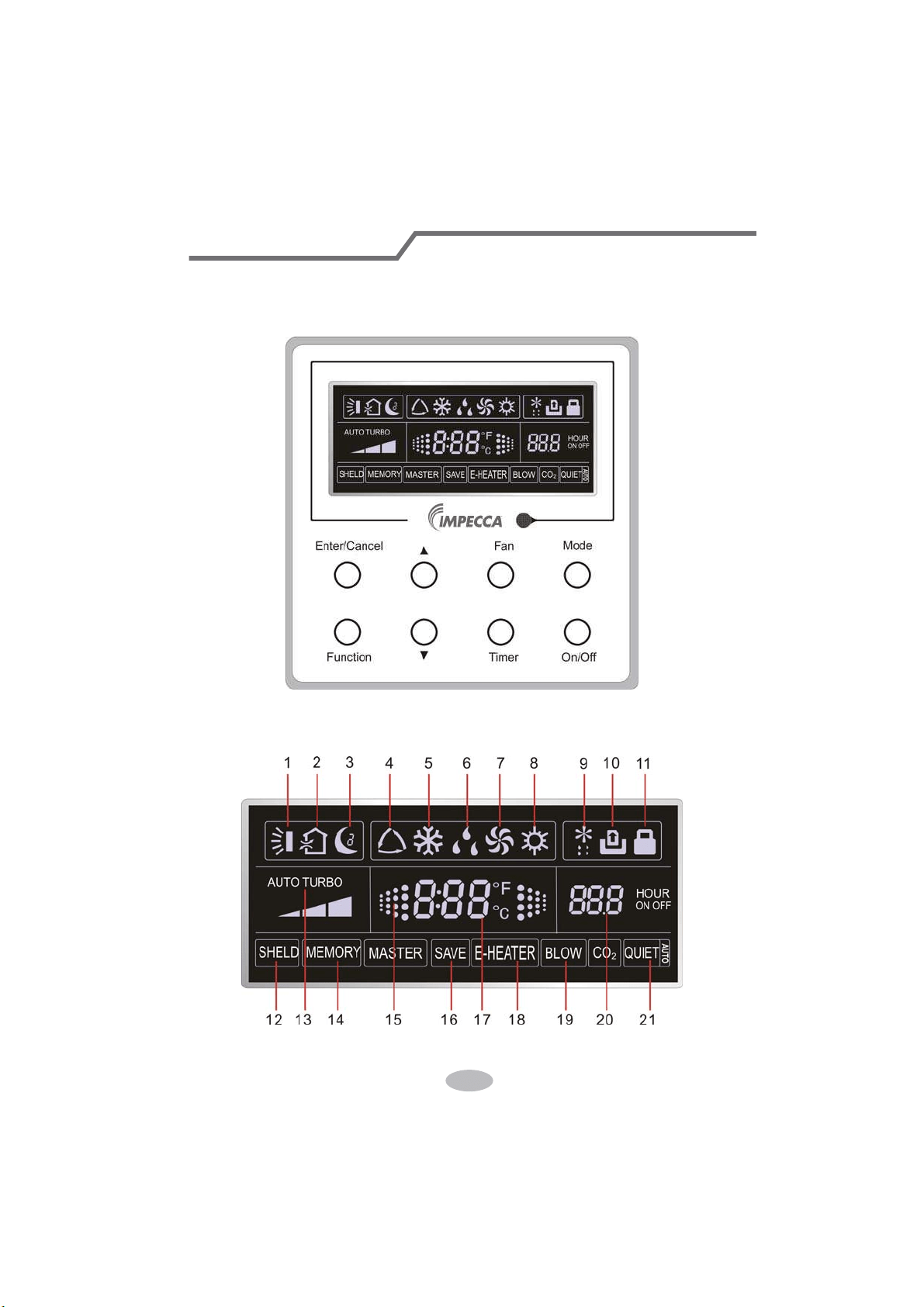
Wired Controller
1 Displaying Part
Fig1.1.1 Outline of wired controller
1.1 LCD Display of Wired Controller
Fig.1.1.2 LCD display
33
If the product you bought is equipped with wired controller, please
refer to the following introductions of wired controller.
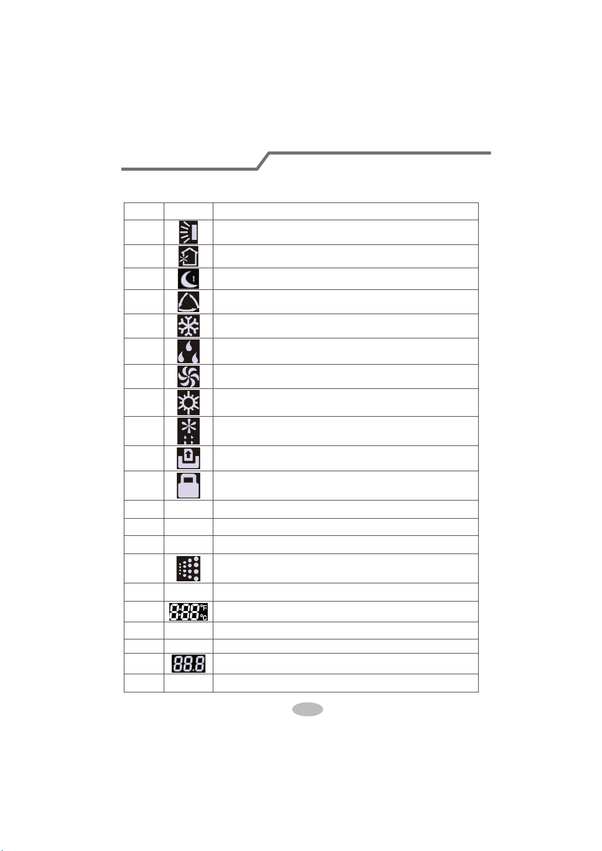
1.2 Instruction to LCD Display
Table 1.1
No. Symbols Description
1
Swing function
2
Air exchange function (this function is yet unavailable for this unit).
3
Sleep function (Only sleep 1).
4
Each kind of running mode of indoor unit (auto mode)
5
Cooling mode
6
Dry mode
7
Fan mode
8
Heating mode
9
Defrosting function for the outdoor unit.
10
Gate-control function (this function is yet unavailable for this unit).
11
Lock function.
12 SHIELD
Shield functions (Button operation, temperature setting, On/Off operation,
Mode setting are disabled by the remote monitoring system.)
13 Turbo Turbo function state
14 MEMORY
Memory function (The indoor unit resumes the original setting state after
power failure and then power recovery).
15
It blinks under on state of the unit without operation of any button.
16
SAVE
Energy-saving function (this function is yet unavailable for this unit).
17
Ambient/setting temperature value
18 E-HEATER Electric auxiliary heating function.
19 BLOW Blow function.
20
Timing value.
21 QUIET
Quiet function (two types: quiet and auto quiet)
(this function is yet unavailable for this unit).
Wired Controller
34
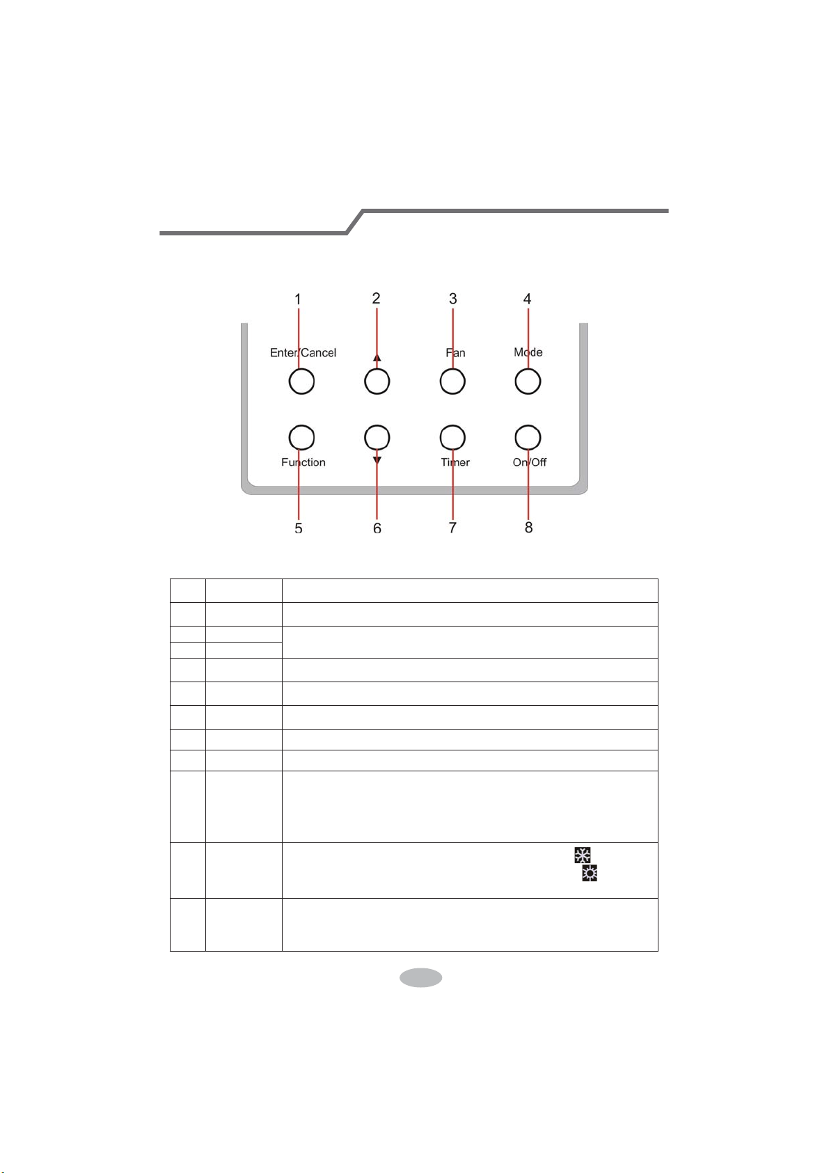
2 Buttons
2.1 Layout of Buttons
2.2 Functions of Buttons
Table 2.1
No. Name Function
1 Enter/Cancel Function selection and cancellation.
2 Ÿ
ķ.
Running temperature setting of the indoor unit, range:16~30
o
C.
ĸ.
Timer setting, range:0.5-24 hr.
6 ź
3 Fan Setting of the high/middle/low/auto fan speed.
4 Mode Setting of the Cooling/Heating/Fan/Dry/Auto mode of the indoor unit.
5 Function Switchover among the functions of Turbo/Save/E-heater/Blow etc..
7 Timer Timer setting.
8 On/Off Turn on/off the indoor unit
4+2 Ÿ0RGH
Press them for 5s under off state of the unit to enter/cancel the Memory
function(If memory is set, indoor unit after power failure and then power
recovery will resume the original setting state. If not, the indoor unit is
defaulted to be off after power recovery. Memory off is default before
delivery.).
3+6 )DQź
By pressing them at the same time under off state of the unit,
will be
displayed on the wired controller for the cooling only unit, while
will be
displayed on the wired controller for the cooling and heating unit.
2+6 Ÿź
Upon startup of the unit without malfunction or under off state of the
unit,press them at the same time for 5s to enter the lock state, in which
case,any other buttons won’t respond the press. Repress them for 5s to quit
this state.
Wired Controller
35
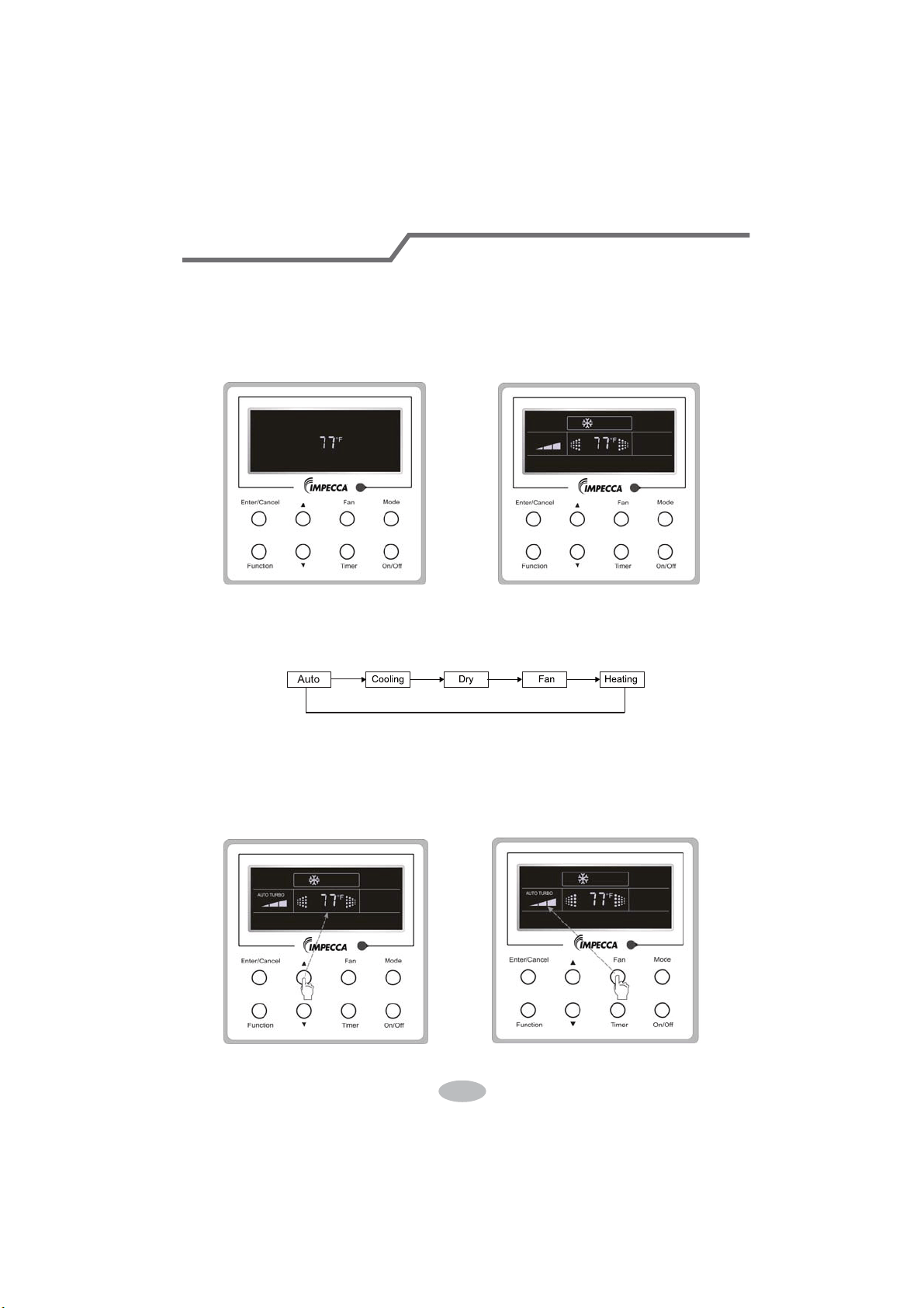
3 Operation Instructions
3.1 On/Off
Press On/Off to turn on the unit and turn it off by another press.
Note: The state shown in Fig.3.1.1 indicates the “Off” state of the unit after power on. The state
shown in Fig.3.1.2 indicates the “On” state of the unit after power on.
Fig.3.1.1 “Off” State Fig.3.1.2 “On” State
3.2 Mode Setting
Under ON state of the unit, press the Mode to switch the operation modes as the following
sequence: Auto–Cooling–Dry–Fan–Heating.
3.3 Temperature Setting
Press Ÿor źto increase/decrease the preset temperature. If pressing either of them
continuously, the temperature will be increased or decreased by 1°C every 0.5s,as shown in
Fig.3.3.1.
In the Cooling, Dry, Fan or Heating mode, the temperature setting range is 16°C~30°C.
In the Auto mode, the setting temperature is unadjustable.
Fig.3.3.1 Fig.3.4.1
Wired Controller
36
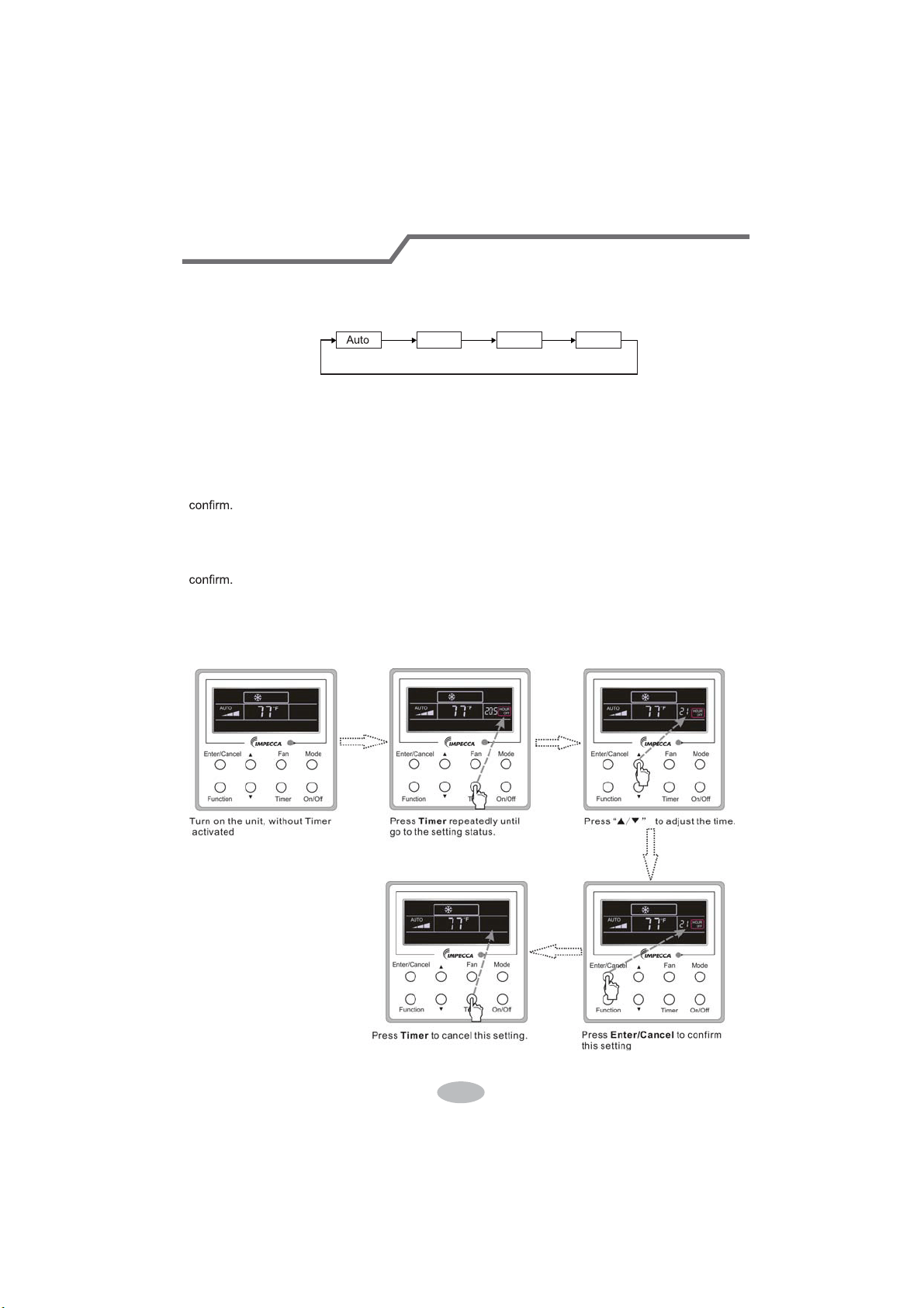
3.4 Fan Setting
Under the “On” state of the unit, press Fan and then fan speed of the indoor unit will change
circularly as shown in Fig.3.4.1.
Low Middle
High
3.5 Timer Setting
Under on-state of the unit, Press Timer button to set timer off of the unit. Under off-state of the
unit, press Timer button to set timer on of the unit in the same way.
Timer on setting:
Under off-state of the unit without timer setting, if Timer button is pressed, LCD will display xx.
Hour,with ON blinking. In this case, SUHVVŸor źbutton to adjust timer on and then press Timer to
Timer off setting:
Under on-state of the unit without timer setting, if Timer button is pressed, LCD will display xx.
HourZLWK2))EOLQNLQJ,QWKLVFDVHSUHVVŸRUźEXWWRQWRDGMXVWWLPHURQDQGWKHQSUHVVTimer to
&DQFHOWLPHU
After setting of timer, if Timer button is pressed, LCD won’t display xx. Hour so that timer setting
is canceled.
Timer off setting under the “On” state of the unit is shown as Fig.3.5.1.
Fig.3.5.1 Timer off Setting under the “On” State of the Unit
Wired Controller
37
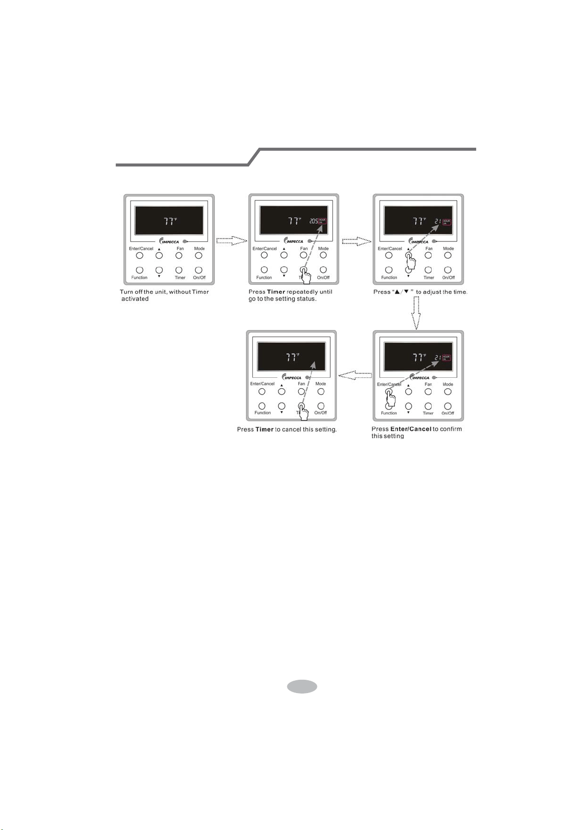
Timer on setting under the “Off” state of the unit is shown as Fig.3.5.2.
Fig.3.5.2 Timer on Setting under the “Off” State of the Unit
Timer range: 0.5-24hr. Every press of ŸRUźwill make the set time increased or decreased by
0.5hr. If either of them is pressed continuously, the set time will increase/ decrease by 0.5hr every
0.5s.
Wired Controller
38
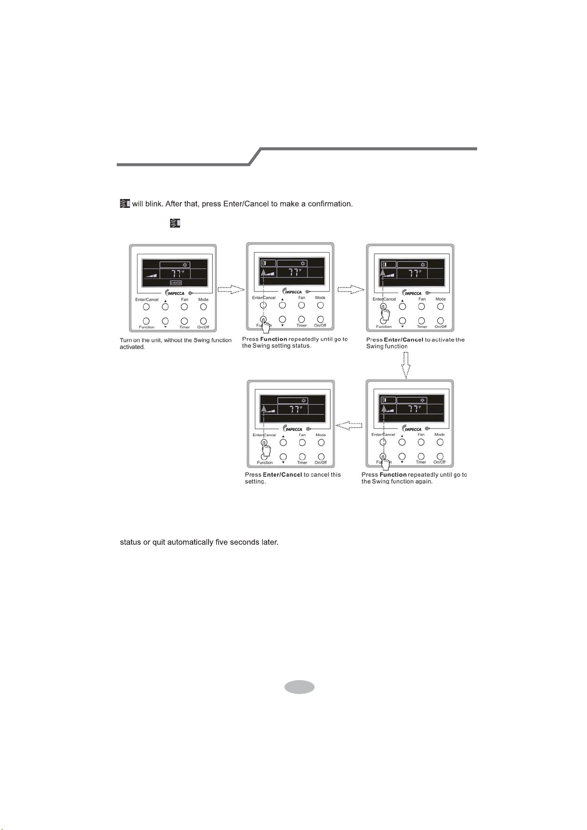
3.6 Swing Setting
Swing On: Press Function under on state of the unit to activate the swing function. In this case,
Swing Off: When the Swing function is on, press Function to enter the Swing setting
interface,with
blinking. After that, press Enter/Cancel to cancel this function. Swing setting is
shown as Fig.3.6.1.
Fig.3.6.1 Swing Setting
Notes:
ķ.
Sleep, Turbo or Blow setting is the same as the Swing setting.
ĸ.
After the setting has been done, it has to press the key “Enter/Cancel” to back to the setting
Wired Controller
39

3.7 Sleep Setting
Sleep on: Press Function under the On state of the unit till the unit enters the Sleep setting
Sleep off: When the Sleep function is activated, press Function to enter the Sleep setting
status. After that, press Enter/Cancel to cancel this function.
In the Cooling or Dry mode, the temperature will increase by 1°C after the unit runs under
Sleep1 for 1hr and 1°C after another 1hr.After that, the unit will run at this temperature.
In the Heating mode, the temperature will decrease by 1°C after the unit runs under Sleep 1 for
1hr and 1°C after another 1hr. After that, the unit will run at this temperature.
Sleep setting is shown as Fig.3.7.1.
Fig.3.7.1. Sleep Setting
Wired Controller
40

3.8 Turbo Setting
Turbo function: The unit at the high fan speed can realize quick cooling or heating so that the
room temperature can quickly approach the setting value.
In the Cooling or Heating mode, press Function till the unit enters the Turbo setting status and
When the Turbo function is activated, press Function to enter the Turbo setting status and then
press Enter/Cancel to cancel this function.
Turbo function setting is as shown in Fig.3.8.1.
Fig.3.8.1 Turbo Setting
Wired Controller
41
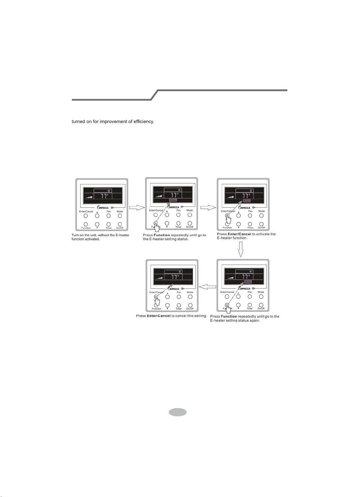
3.9 E-heater Setting
E-heater (auxiliary electric heating function): In the Heating mode, E-heater is allowed to be
Once the wired controller or the remote controller enters the Heating mode, this function will be
turned on automatically.
Press Function in the Heating mode to enter the E-heater setting interface and then press
Enter/Cancel to cancel this function.
Press Function to enter the E-heater setting status, if the E-heater function is not activated,
and then press Enter/Cancel to activate it.
The setting of this function is shown as Fig.3.9.1 below:
Fig.3.9.1 E-heater Setting
Wired Controller
42

3.10 Blow Setting
Blow function: After the unit is turned off, the water in evaporator of indoor unit will be
automatically evaporated to avoid mildew.
In the Cooling or Dry mode, press Function till the unit enters the Blow setting status and then
press Enter/Cancel to active this function.
When the Blow function is activated, press Function to the Blow setting status and then press
Enter/Cancel to cancel this function.
Blow function setting is as shown in Fig.3.10.1
Fig.3.10.1 Blow Setting
Notes:
ķ.
When the Blow function is activated, if turning off the unit by pressing On/Off or by the
remote controller, the indoor fan will run at the low fan speed for 2 min, with “BLOW” displayed on
the LCD. While, if the Blow function is deactivated, the indoor fan will be turned off directly.
ĸ.
Blow function is unavailable in the Fan or Heating mode.
Wired Controller
43
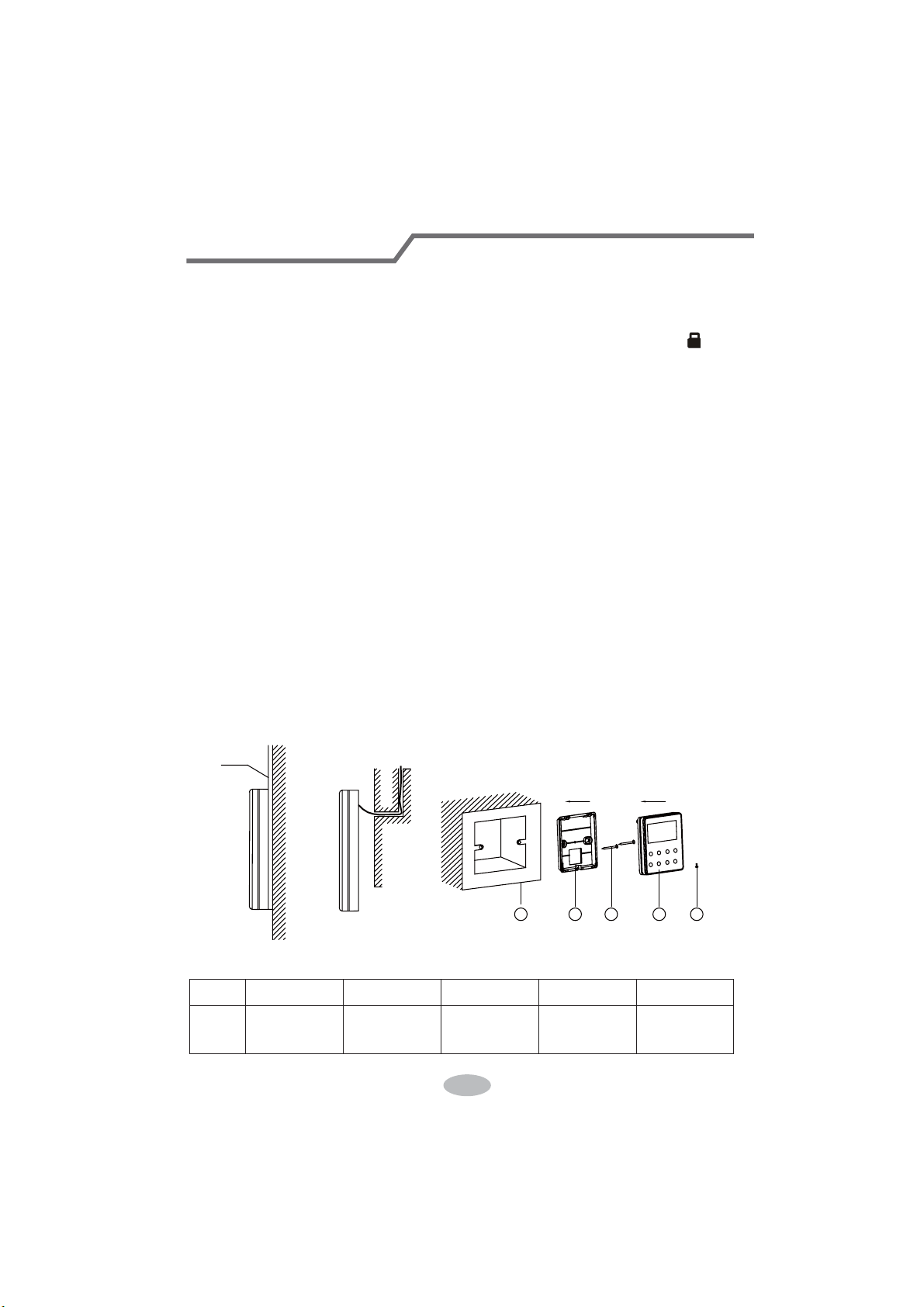
3.11 Other Functions
a. Lock
Upon startup of the unit without malfunction or under the “Off” state of the unit, press Ÿand źat
the same time for 5s till the wired controller enters the Lock function. In this case, LCD displays
.
After that, repress these two buttons at the same time for 5s to quit this function.
Under the Lock state, any other button press won’t get any response.
b. Memory
Memory switchover: Under the “Off” state of the unit, press Mode and Ÿat the same time for
5s to switch memory states between memory on and memory off. When this function is activated,
Memory will be displayed. If this function is not set, the unit will be under the “Off” state after power
failure and then power recovery.
Memory recovery: If this function has been set for the wired controller, the wired controller after
power failure will resume its original running state upon power recovery. Memory contents: On/
Off, Mode, set temperature, set fan speed and Lock function.
4 Installation and Dismantlement
4.1 Connection of the Signal Line of the Wired Controller
Ɣ2SHQWKHFRYHURIWKHHOHFWULFFRQWUROER[RIWKHLQGRRUXQLW
Ɣ/HWWKHVLQJOHOLQHRIWKHZLUHGFRQWUROOHUWKURXJKWKHUXEEHUULQJ
Ɣ&RQQHFWWKHVLJQDOOLQHRIWKHZLUHGFRQWUROWRWKHSLQVRFNHWRIWKHLQGRRUXQLW3&%
ƔTighten the signal wire with ties.
ƔThe communication distance between the main board and the wired controller can be up to
20 meters ( the standard distance is 8 meters)
4.2 Installation of the Wired Controller
1
39&3LSH
3 4 52
Fig.4.1 Accessories for the Installation of the Wired Controller
Table 4.1
No. 1 2 3 4 5
Name
6RFNHWER[
embedded
in the wall
Soleplate of
the Wired
Controller
Screw
M4X25
)URQW3DQHO
of the Wired
Controller
Screw
ST 2.9X6
Wired Controller
44
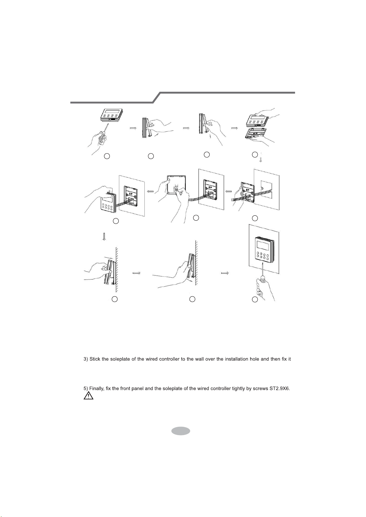
1
6
8 9
10
7
3 4
5
2
Fig.4.2
Fig.4.2 shows the installation steps of the wired controller, but there are some issues that need
your attention.
1) Prior to the installation, please firstly cut off the power supply of the wire buried in the
installation hole, that is, no operation is allowed with electricity during the whole installation.
2) Pull out the four-core twisted pair line from the installation holes and then let it go through
the rectangular hole behind the soleplate of the wired controller.
with screws M4X25.
4) Insert the four-core twisted pair line into the slot of the wired controller and then buckle the
front panel and the soleplate of the wired controller together.
CAUTION!
Please pay special attention to the followings during the connection to avoid the malfunction of
the air conditioning unit due to electromagnetic interference.
ķ.
Separate the signal and communication lines of the wired controller from the power cord
Wired Controller
45
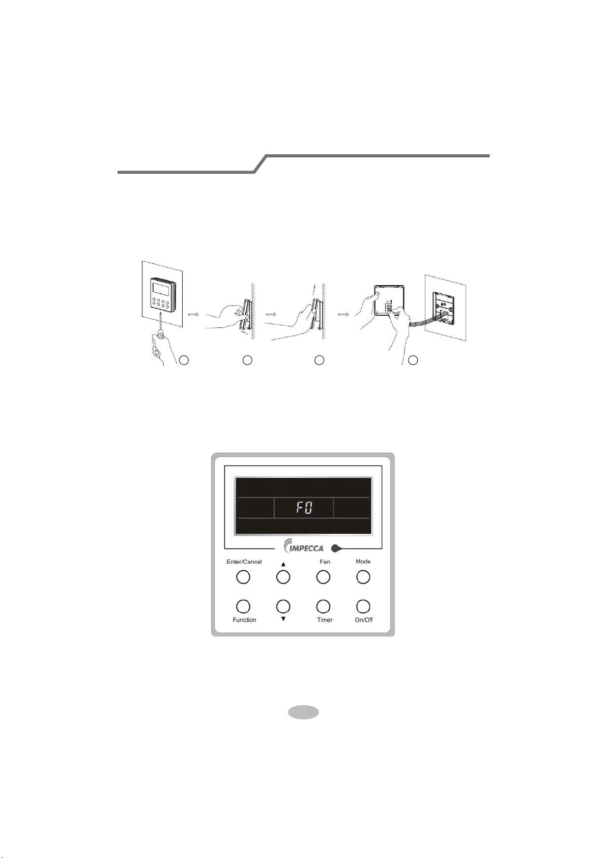
and connection lines between the indoor and outdoor unit, with a minimum interval of 20cm,
otherwise the communication of the unit will probably work abnormally.
ĸ.
If the air conditioning unit is installed where is vulnerable to electromagnetic
interference,then the signal and communication lines of the wired controller must be the shielding
twisted pair lines.
4.3 Dismantlement of the Wired Controller
1 3 42
5 Errors Display
If there is an error occurring during the operation of the system, the error code will be displayed
on the LCD, as show in Fig.5.1. If multi errors occur at the same time, their codes will be displayed
circularly.
Note: In event of any error, please turn off the unit and contact the professionally skilled
personnel.
Fig.5.1
Wired Controller
46
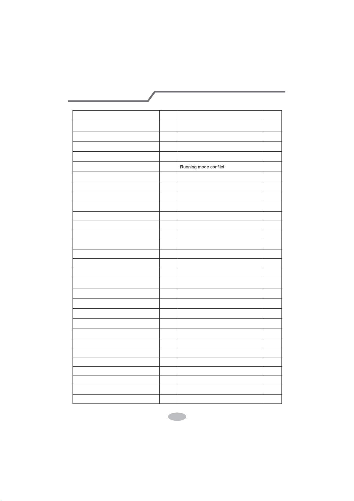
Table 5.1 Meaning of Each Error
Error
Error
Code
Error
Error
Code
Return air temperature sensor open/
short circuited
F1 Drive board communication error P6
evaporator temperature sensor open/
short circuited
F2 Compressor overheating protection H3
Indoor unit liquid valve temperature
sensor open/short circuited
b5 Indoor and outdoor units unmatched LP
Indoor gas valve temperature sensor
open/ short circuited
b7
Communication line misconnected or
expansion valve error
dn
IPM temperature sensor open/short
circuited
P7
E7
Outdoor ambient temperature sensor
open/ short circuited
F3 Pump-down Fo
Outdoor unit condenser mid-tube
temperature sensor open/short circuited
F4 Jumper error C5
Discharge temperature sensor open/
short circuited
F5 Forced defrosting H1
Indoor and outdoor communication error E6 Compressor startup failure Lc
DC bus under-voltage protection PL High discharge temperature protection E4
DC bus over-voltage protection PH Overload protection E8
Compressor phase current sensing
circuit error
U1 Whole unit over-current protection E5
Compressor demagnetization protection HE Over phase current protection P5
PFC protection Hc Compressor desynchronizing H7
IPM Temperature Protection P8 IPM Current protection H5
Over-power protection L9
Compressor phase loss/reversal
protection
Ld
System charge shortage or blockage
protection
F0
Frequency restricted/reduced with whole
unit current protection
F8
Capacitor charging error PU
Frequency restricted/reduced with IPM
current protection
En
High pressure protection E1
Frequency restricted/reduced with high
discharge temperature
F9
Low pressure protection E3
Frequency restricted/reduced with anti-
freezing protection
FH
Compressor stalling LE
Frequency restricted/reduced with
overload protection
F6
Over-speeding LF
Frequency restricted/reduced with IPM
temperature protection
EU
Drive board temperature sensor error PF Indoor unit full water error E9
AC contactor protection P9 Anti-freezing protection E2
Temperature drift protection PE AC input voltage abnormal PP
Sensor connection protection Pd Whole unit current sensing circuit error U5
DC bus voltage drop error U3 4-way valve reversing error U7
Outdoor fan 1 error protection L3 Motor stalling H6
Outdoor fan 2 error protection LA PG motor zero-crossing protection U8
Wired Controller
47

CUSTOMER SUPPORT
Before contacting customer support, please see the troubleshooting guide above.
Visit our website to contact us, find answers to Frequently Asked Questions, and for other
resources which may include an updated version of this user's guide.
WWW.IMPECCA.COM
If you wish to contact us by phone, please be sure to have your model number and serial
number ready and call us between 9:00am and 6:00pm ET, at +1 866-954-4440.
Keep tabs on Impecca's newest innovations & enter contests via our social network feeds:
www.facebook.com/Impecca/
www.instagram.com/impecca/
@impeccausa

© 2016 Impecca, a division of LT Inc., Wilkes Barre, PA.