
NUCLIAS CONNECT
DAP-2662 User Guide
V 1.01
2020 |
Business Class Networking

2
Table of Contents
Nuclias Connect .........................................................................4
Introduction ................................................................................... 4
Nuclias Connect Key Features .................................................. 5
Package Contents .........................................................................6
System Requirements ................................................................. 6
Hardware Overview ..................................................................7
LEDs ................................................................................................... 7
Connections ................................................................................... 7
Basic Installation ........................................................................8
Hardware Setup ............................................................................ 8
Congure the Access Point ............................................... 8
Setup Wizard ........................................................................... 10
Web User Interface ................................................................. 11
Wireless ..........................................................................................12
Access Point Mode .............................................................12
WDS with AP Mode ............................................................14
WDS Mode ............................................................................16
Wireless Client Mode .........................................................18
Wireless Security .................................................................19
Wired Equivalent Privacy (WEP) ..............................19
Wi-Fi Protected Access (WPA / WPA2)....................20
LAN ..........................................................................................22
IPv6 ..........................................................................................23
Advanced Settings .....................................................................24
Performance .........................................................................25
Wireless Resource Control .......................................................27
Multi-SSID ..............................................................................29
VLAN ........................................................................................31
VLAN List ..........................................................................31
Port List ............................................................................. 32
Add/Edit VLAN ...............................................................33
PVID Settings ..................................................................34
Intrusion .................................................................................35
Schedule ................................................................................36
Internal RADIUS Server .....................................................37
ARP Spoong Prevention ................................................38
Bandwidth Optimization .................................................39
Hotspot 2.0 ............................................................................ 41
Hotspot ............................................................................. 41
Inter work ing ...................................................................42
WAN Metrics ...................................................................43
LIST .....................................................................................44
OSU ....................................................................................45
Captive Portal ....................................................................... 47
Authentication Settings-Web Redirection Only 47
Authentication Settings- Username/Password .. 49
Authentication Settings- Passcode ........................51
Authentication Settings- Remote RADIUS ........... 53
Authentication Settings- LDAP ................................55
Authentication Settings- POP3 ................................57
Login Page Upload .......................................................59

3
MAC Bypass .....................................................................60
DHCP Server .........................................................................61
Dynamic Pool Settings ................................................ 61
Static Pool Setting ........................................................62
Current IP Mapping List ..............................................63
Filters .......................................................................................64
Wireless MAC ACL .........................................................64
IP Filter Settings ............................................................. 65
WLAN Partition ..............................................................66
Trac Control...............................................................................67
Uplink/Downlink Setting .................................................67
QoS...........................................................................................68
Trac Manager ....................................................................69
Status ..............................................................................................70
Device Information ............................................................71
Client Information ..............................................................72
WDS Information Page .....................................................73
Statistics .........................................................................................74
Ethernet Trac Statistics ..................................................74
WLAN Trac Statistics ....................................................... 75
Log ...................................................................................................76
View Log .................................................................................76
Log Settings ..........................................................................77
Maintenance Section ................................................................78
Administration ............................................................................. 79
Limit Administrator ............................................................79
System Name Settings ......................................................80
Login Settings ......................................................................80
Console Settings .................................................................81
Ping Control Settings ........................................................81
LED Settings..........................................................................81
Country Settings .................................................................81
DDP Settings ........................................................................82
Nuclias Connect Settings .................................................82
Firmware and SSL Upload ................................................83
Conguration File Upload ...............................................84
Time and Date Settings ....................................................85
Conguration and System.......................................................86
System Settings ........................................................................... 87
Help .................................................................................................88
Knowledge Base ..................................................................... 89
Wireless Basics .............................................................................89
Wireless Installation Considerations .................................... 90
Troubleshooting ..................................................................... 91
Why can’t I access the web-based conguration
utility? .....................................................................................91
What can I do if I forgot my password? .......................91
How to check your IP address? ......................................92
How to statically assign an IP address? ....................... 93
Technical Specications ........................................................ 94
Antenna Pattern ..................................................................... 95

Nuclias Connect
4
Nuclias Connect
Introduction
Nuclias Connect is D-Link’s centralized management solution for Small-to-Medium-Sized Business (SMB) networks. Nuclias Connect makes it easier
to analyze, automate, congure, optimize, scale, and secure your network — delivering the convenience of an Enterprise-wide management
solution, at an SMB price. Nuclias Connect gives you the nancial and technical exibility to expand from a small network to a larger one (up
to 1,000 APs), while retaining a robust and centralized management system. And with its intuitive Graphical User Interface (GUI), a wealth of
enhanced AP features, and a setup wizard that supports 11 languages, Nuclias Connect minimizes the hassle of deployment, conguration,
and administration tasks.
Deployable on Windows server (or Linux via Docker), PC, or Smartphone (via lite management app) the Nuclias Connect free-to-download
software is capable of managing up to 1,000 Access Points (APs) without licensing charges, coupled with an inexpensive optional
hardware controller (The Hub) suitable for remote locations. Through software-based monitoring and remote management of all wireless Access
Points (APs) on your network, Nuclias Connect oers tremendous exibility compared to traditional hardware-based unied
management systems. Conguration can be done remotely. Network trac analytics are available at a glance (in whole or in part). Load Balancing,
Airtime Fairness, and Localized Throttling are enabled.
Nuclias Connect supports multi-tenancy, so network admins can grant localized management authority for local networks. In addition, because
APs can support 8 SSIDs per radio (16 SSIDs per dual band APs), administrators have the option of using one SSID to create a guest network for
visitors.
Nuclias Connect provides direct AP discovery and provisioning when it shares the same Layer-2/Layer-3 network with a given AP, allowing
users to nd APs and import proles with minimum eort, which can be applied as needed to groups or individual APs for even more eective
conguration.
Since Nuclias Connect’s software operates transparently on the network, an AP can be deployed anywhere in an NAT environment. Admins can
provide & manage a variety of distributed deployments, including setting & admin account conguration for each deployment.
Nuclias Connect allows for multiple user authentications while enabling specic access control congurations for each SSID, giving admins the
option of conguring separate internal networks for dierent subnets, while enabling more advanced Value-Added Services, such as Captive
Portal or Wi-Fi Hotspot.

Nuclias Connect
5
Nuclias Connect Key Features
• Free-to-Download Management Software
• Searchable Event Log and Change Log
• License-Free Access Points
• Trac Reporting & Analytics
• Authentication via Customizable Captive Portal, 802.1x and RADIUS Server, POP3, LDAP, AD
• Remote Cong. & Batch Cong.
• Multilingual Support
• Intuitive Interface
• Multi-Tenant & Role-Based Administration
• Payment Gateway (Paypal) Integration and Front-Desk Ticket Management
For more information on how to use Nuclias Connect with DAP-2662, please refer to the Nuclias Connect User Guide.

Nuclias Connect
6
Package Contents
• DAP-2662 Access Point
• Power Adapter
• Mounting Plate and Hardware
Note: Using a power supply with a dierent voltage rating than the one included with the DAP-2662 will cause damage and void the warranty for this product.
System Requirements
y Computers with Windows®, Macintosh®, or Linux-based operating systems with an Ethernet Adapter
y Internet Explorer 11, Safari 7, Firefox 28, or Google Chrome 33 and above (for web-based conguration)
Hardware Overview
7
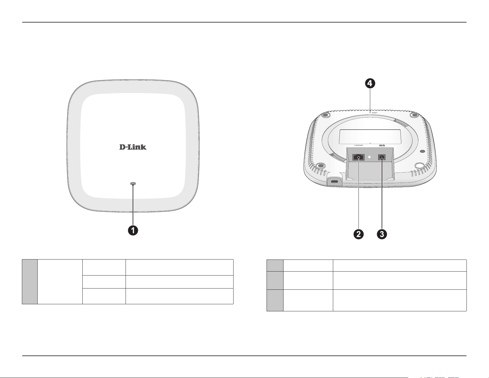
Hardware Overview
LEDs Connections
2 Power Receptor Connect the supplied power adapter.
3 LAN (PoE) Port
Connect to a Power over Ethernet (PoE) switch or router
via an Ethernet cable.
4 Reset Button
Press and hold for ve seconds to reset the access point
to the factory default settings. Press and hold for one
second to reboot the access point.
1 Power/Status
Solid Red Indicates the access point has malfunctioned.
Blinking Red This LED will blink during boot-up.
Solid Green
Indicates that the DAP-2662 is working
properly.
Basic Installation
8
Basic Installation
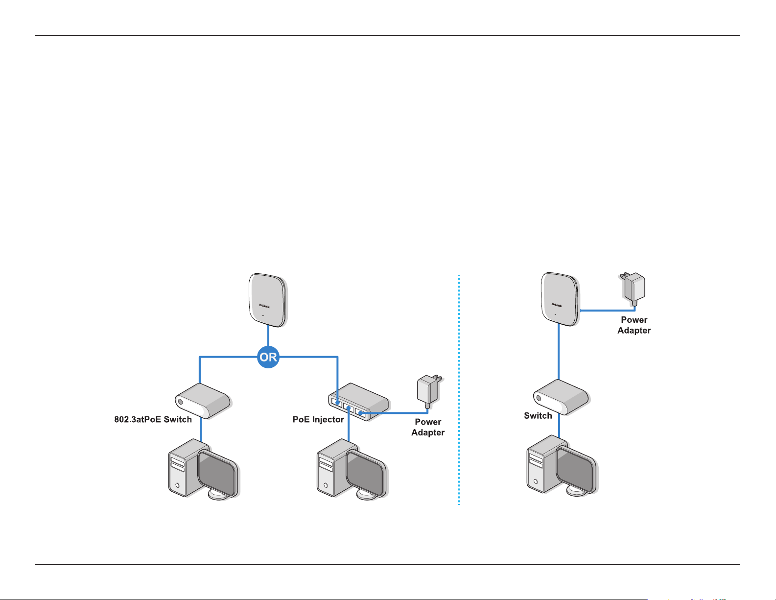
Hardware Setup
To power on the DAP-2662, you can use ONE of the following methods:
1. Plug one end of your Ethernet cable into the LAN port of the DAP-2662, and the other end into a port on a 802.3at PoE switch.
2. Separately purchase a DPE-301GI PoE injector if you need to connect the Access Point without a 802.3at PoE Switch.
3. Separately purchase a power adaptor to plug into the power receptor of the DAP-2662
Congure the Access Point
Computer with DHCP Server
Computer with DHCP Server
Computer with DHCP Server

Basic Installation
9
To set up and manage the DAP-2662, use one of the following methods:
1. Connect the access point and your computer to the same PoE switch. Manage the access point from the computer.
Enter dap2662.local in the address eld of your browser.
Log in to the Administration user interface. The default login information is:
Username: admin
Password: admin
2. Connect the access point and your computer via DPE-301GI PoE injector. Manage the access point from the computer.
Enter dap2662.local in the address eld of your browser.
Log in to the Administration user interface. The default login information is:
Username: admin
Password: admin
3. Connect the access point and your computer to the same network switch. Manage the access point from the computer.
Enter dap2662.local in the address eld on your browser.
Log in to the Administration user interface. The default login information is:
Username: admin
Password: admin
Setup Wizard
10
Setup Wizard
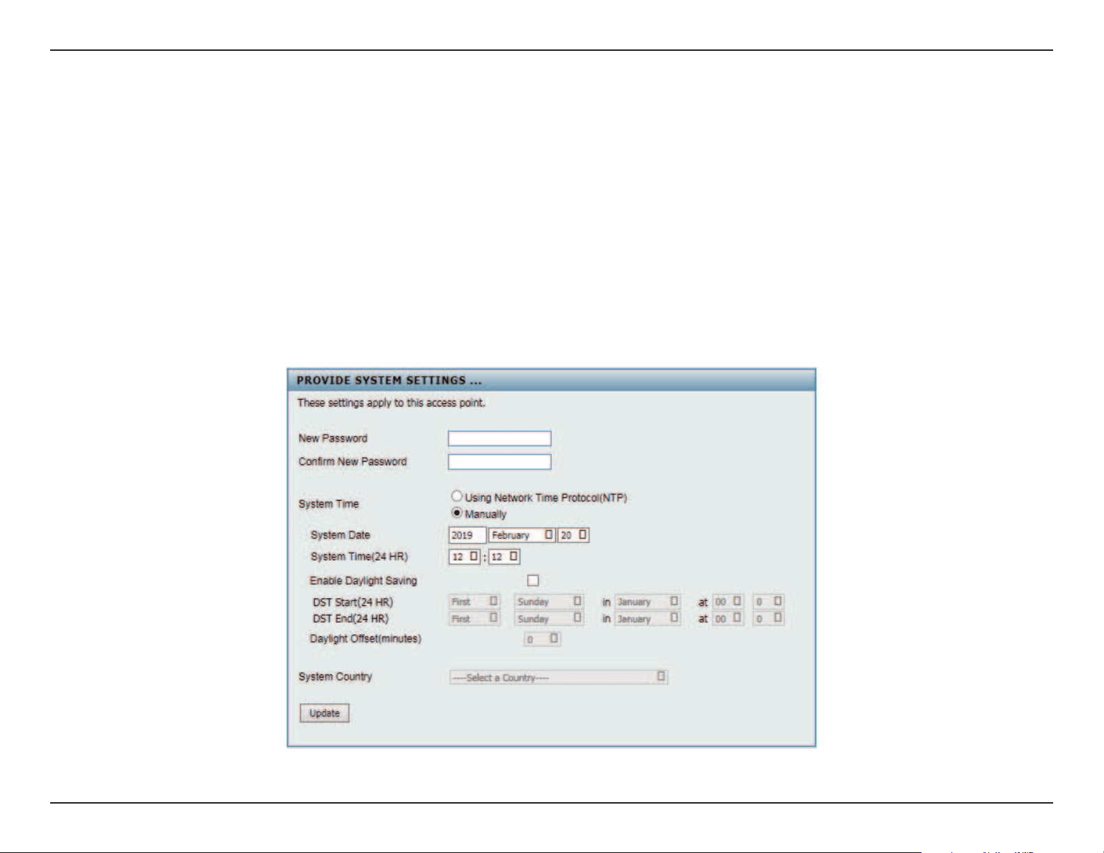
The rst login instance displays the System Settings window which requires a change in password. Additional settings include the System Time
and System Country functions.
After logging in to the user interface, ll in the New Password and Conrm New Password elds.
In the System Time function, select Using Network Time Protocol (NTP) or Manually to dene the system time. If required, click the Daylight Sav-
ing Oset drop-down menu and select the value (minutes).
y Setting NTP System Time: Before trying to congure NTP check, perform a ping test with the NTP server. In the NTP Server eld, enter the NTP
server to use. Then click the Time Zone drop-down menu and select the appropriate time zone.
y Setting System Time Manually: From the System Date drop-down menu, select the Year, Month, and Day along with the Hour and Minutes ap-
propriate for the AP.
y Enable Daylight Saving: Click the radio button to enable the daylight savings time (DST) function. Set the DST start (24 hours) and end (24
hours) time by clicking on the drop-down menus and setting the Month, Week, Day, Hour, and Minute of the DST starting days.
Once the settings are congured, click Update button to accept the conguration and proceed to the main interface menu page.
Web User Interface
11
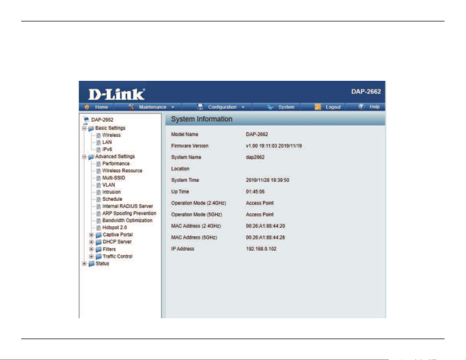
Web User Interface
The DAP-2662 supports an elaborate web user interface where the user can congure and monitor the device. Launch a web browser, type in
http://dap2662.local/ and then press Enter to login. The default username and password is: admin Most of the congurable settings are located
in the menu on the left side of the web GUI which contains sections called Basic Settings, Advanced Settings and Status.
Web User Interface
12
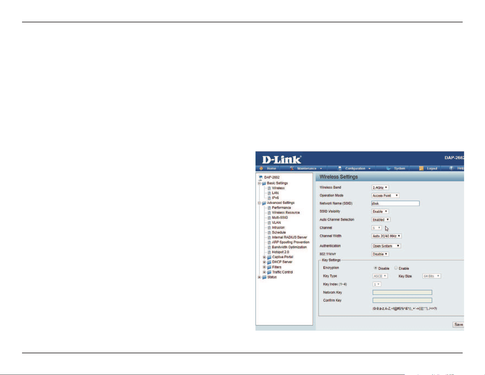
Wireless
On the wireless settings page, you can setup the basic wireless conguration for the access point. The user can choose from 4 dierent wireless
modes:
• Access Point - Used to create a wireless LAN
• WDS with AP - Used to connect multiple wireless networks while still functioning as a wireless access point
• WDS - Used to connect multiple wireless networks
• Wireless Client - Used when the access point needs to act as a wireless network adapter for an Ethernet enabled device
Wireless Band:
Mode:
Network Name (SSID):
SSID Visibility:
Auto Channel Selection:
Select either 2.4 GHz or 5 GHz from the drop-down
menu.
Select Access Point from the drop-down menu.
Service Set Identier (SSID) is the name designated
for a specic wireless local area network (WLAN).
The SSID’s factory default setting is dlink. The SSID
can be easily changed to connect to an existing
wireless network or to establish a new wireless
network. The SSID can be up to 32 characters and
is case-sensitive.
Select Enable to broadcast the SSID across the
network, thus making it visible to all network users.
Select Disable to hide the SSID from the network.
This feature when enabled automatically selects
the channel that provides the best wireless
performance. The channel selection process only
occurs when the AP is booting up. To manually
select a channel, set this option to Disable and
select a channel from the drop-down menu.
Access Point Mode

Web User Interface
13
Channel:
Channel Width:
Authentication:
802.11k/v/r:
To change the channel, rst toggle the Auto Channel Selection setting to Disable, and then use the drop-down menu to make
the desired selection.
Note: The wireless adapters will automatically scan and match the wireless settings.
Allows you to select the channel width you would like to operate in. Select 20 MHz if you are not using any 802.11n wireless
clients. Auto 20/40 MHz allows you to connect to both 802.11n and 802.11b/g or 802.11a wireless devices on your network.
Use the drop-down menu to choose Open System, Shared Key, WPA-Personal, WPA-Enterprise, or 802.1x.
• Select Open System to communicate the key across the network (WEP).
• Select Shared Key to limit communication to only those devices that share the same WEP settings. If multi-SSID is
enabled, this option is not available.
• Select WPA-Personal to secure your network using a password and dynamic key. No RADIUS server is required.
• Select WPA-Enterprise to secure your network with the inclusion of a RADIUS server.
• Select 802.1X if your network is using port-based Network Access Control.
Use the drop-down menu to choose to enable or disable 802.11k/v/r
Web User Interface
14
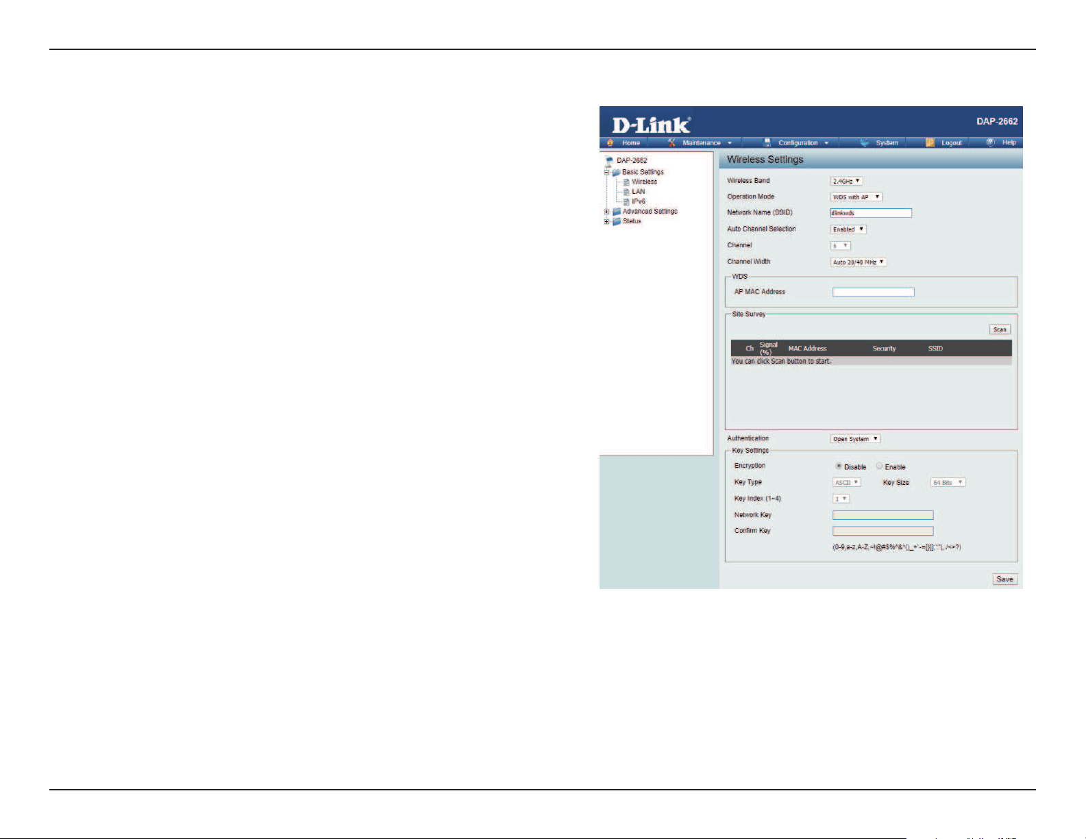
Wireless Band:
Mode:
Network Name (SSID):
SSID Visibility:
Auto Channel Selection:
Channel:
Channel Width:
Select either 2.4GHz or 5GHz from the drop-down
menu.
WDS with AP mode is selected from the drop-down
menu.
Service Set Identier (SSID) is the name designated
for a specic wireless local area network (WLAN).
The SSID’s factory default setting is dlink. The SSID
can be easily changed to connect to an existing
wireless network or to establish a new wireless
network.
Enable or Disable SSID visibility. Enabling this
feature broadcasts the SSID across the network,
thus making it visible to all network users.
Enabling this feature automatically selects
the channel that will provide the best wireless
performance. This feature is not supported in WDS
with AP mode. The channel selection process only
occurs when the AP is booting up.
All devices on the network must share the same
channel. To change the channel, use the drop-down
menu to make the desired selection. (Note: The
wireless adapters will automatically scan and match
the wireless settings.)
Allows you to select the channel width you would
like to operate in. Select 20 MHz if you are not using
any 802.11n wireless clients. Auto 20/40 MHz allows
you to connect to both 802.11n and 802.11b/g or
802.11a wireless devices on your network.
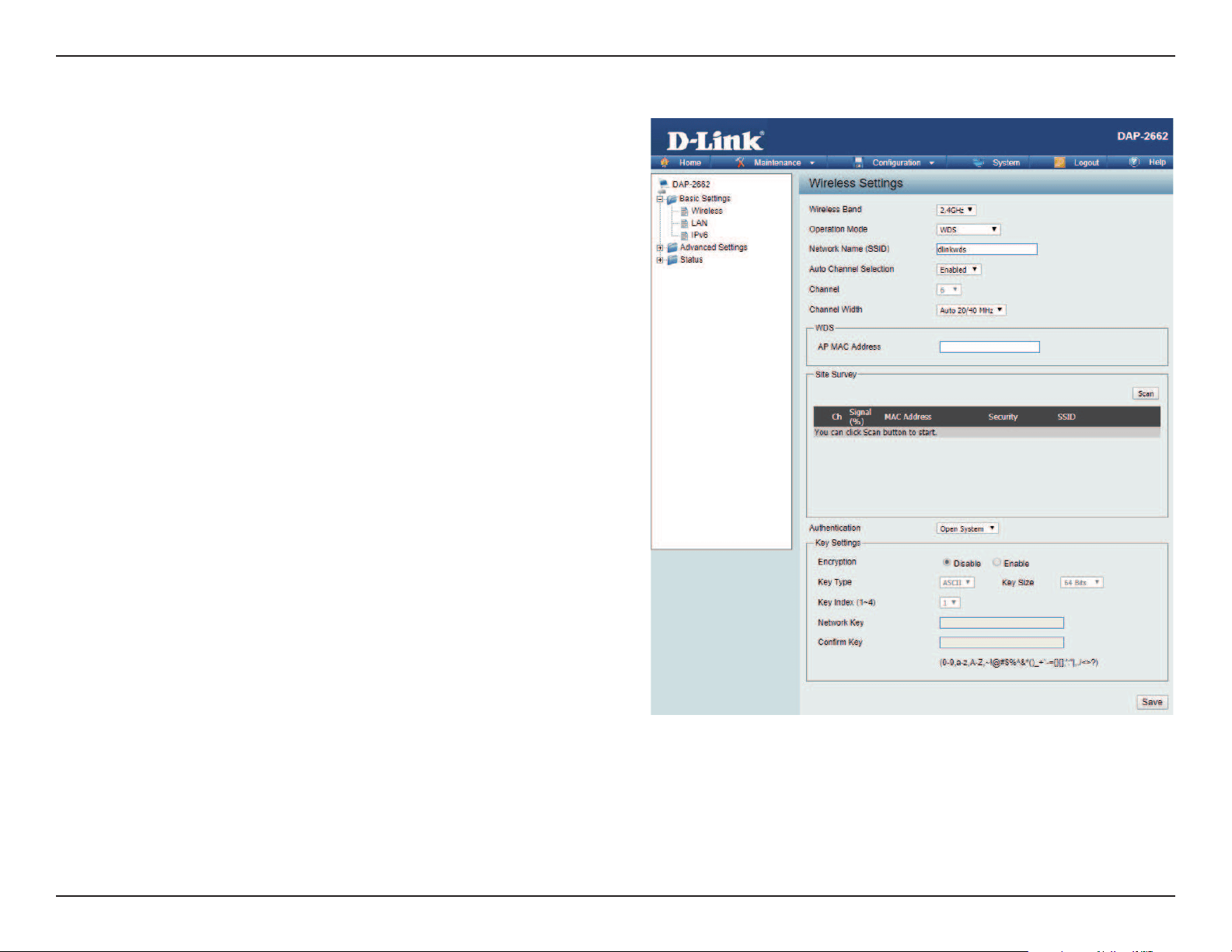
WDS with AP Mode

Web User Interface
15
Remote AP MAC
Address:
Site Survey:
Authentication:
Enter the MAC addresses of the APs on your network that will serve as bridges to wirelessly connect multiple networks.
Click on the Scan button to search for available wireless networks, then click on the available network that you want to
connect with.
Use the drop-down menu to choose Open System, or WPA-Personal.
• Select Open System to communicate the key across the network.
• Select WPA-Personal to secure your network using a password and dynamic key changes. No RADIUS server is required.
Web User Interface
16
Wireless Band:
Mode:
Network Name (SSID):
Auto Channel
Selection:
Channel:
Channel Width:
Remote AP MAC
Address:
Select either 2.4GHz or 5GHz from the drop-down
menu.
WDS is selected from the drop-down menu.
Service Set Identier (SSID) is the name designated
for a specic wireless local area network (WLAN). The
SSID’s factory default setting is dlink. The SSID can
be easily changed to connect to an existing wireless
network or to establish a new wireless network.
Enabling this feature automatically selects
the channel that will provide the best wireless
performance. This feature is not supported in WDS
mode.
All devices on the network must share the same
channel. To change the channel, use the drop-down
menu to make the desired selection.
Use the drop-down menu to choose 20 MHz or
Auto 20/40 MHz.
Enter the MAC addresses of the APs on your network
that will serve as bridges to wirelessly connect
multiple networks.
WDS Mode

Web User Interface
17
Site Survey:
Authentication:
Click on the Scan button to search for available wireless networks, then click on the available network that you
want to connect with.
Use the drop-down menu to choose Open System, or WPA-Personal.
• Select Open System to communicate the key across the network.
• Select WPA-Personal to secure your network using a password and dynamic key changes. No RADIUS server is
required.
Web User Interface
18
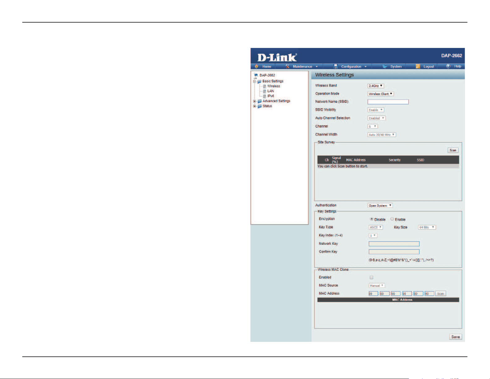
Wireless Band:
Mode:
Network Name (SSID):
SSID Visibility:
Auto Channel Selection:
Channel:
Channel Width:
Site Survey:
Authentication:
Select either 2.4 GHz or 5 GHz from the drop-down
menu.
Wireless Client is selected from the drop-down menu.
Service Set Identier (SSID) is the name designated
for a specic wireless local area network (WLAN). The
SSID’s factory default setting is dlink. The SSID can
be easily changed to connect to an existing wireless
network.
This option is unavailable in Wireless Client mode.
Enabling this feature automatically selects the channel
that will provide the best wireless performance. This
feature is not supported in Wireless Client mode.
The channel used will be displayed, and matches the
AP that the DAP-2662 is connected to when set to
Wireless Client mode.
Use the drop-down menu to choose 20 MHz or Auto
20/40 MHz.
Click on the Scan button to search for available
wireless networks, then click on the available network
that you want to connect with.
Will be explained in the next topic.
Wireless Client Mode
Web User Interface
19
Wireless security is a key concern for any wireless network installed. Wireless networks will broadcast it’s presence for anyone to connect to it. Today, wireless
security has advanced to a level where it is virtually impenetrable.
There are mainly two forms of wireless encryption and they are called Wired Equivalent Privacy (WEP) and Wi-Fi Protected Access (WPA). WEP was the rst
security method developed. It is a low level encryption but better than no encryption. WPA is the newest encryption protocol. With the advanced WPA2
standard wireless networks have nally reach a point where the security is strong enough to give users the peace of mind when installing wireless networks.
Wireless Security
Wired Equivalent Privacy (WEP)
Encryption:
Key Type*,**:
Key Size:
Key Index (1-4):
Key:
Use the radio button to disable or enable
encryption.
Select HEX or ASCII.
Select 64 Bits or 128 Bits.
Select the 1st through the 4th key to be the active
key.
Input up to four keys for encryption. You will select
one of these keys in the Key Index drop-down
menu.
**Hexadecimal (HEX) digits consist of the numbers 0-9 and the letters A-F.
*ASCII (American Standard Code for Information Interchange) is a code that represents English letters using
numbers ranging from 0-127.
WEP provides two variations called Open System and Shared Key.
Open System sends a request to the access point and if the key used matches the one congured on the access point, the access point will return a success
message back to the wireless client. If the key does not match the one congured on the access point, the access point will deny the connection request from
the wireless client.
Shared Key sends a request to the access point and if the key used matches the one congured on the access point, the access point will send a challenge
to the client. The client will then again send a conrmation of the same key back to the access point where the access point will either return a successful or a
denial packet back to the wireless client.

Web User Interface
20
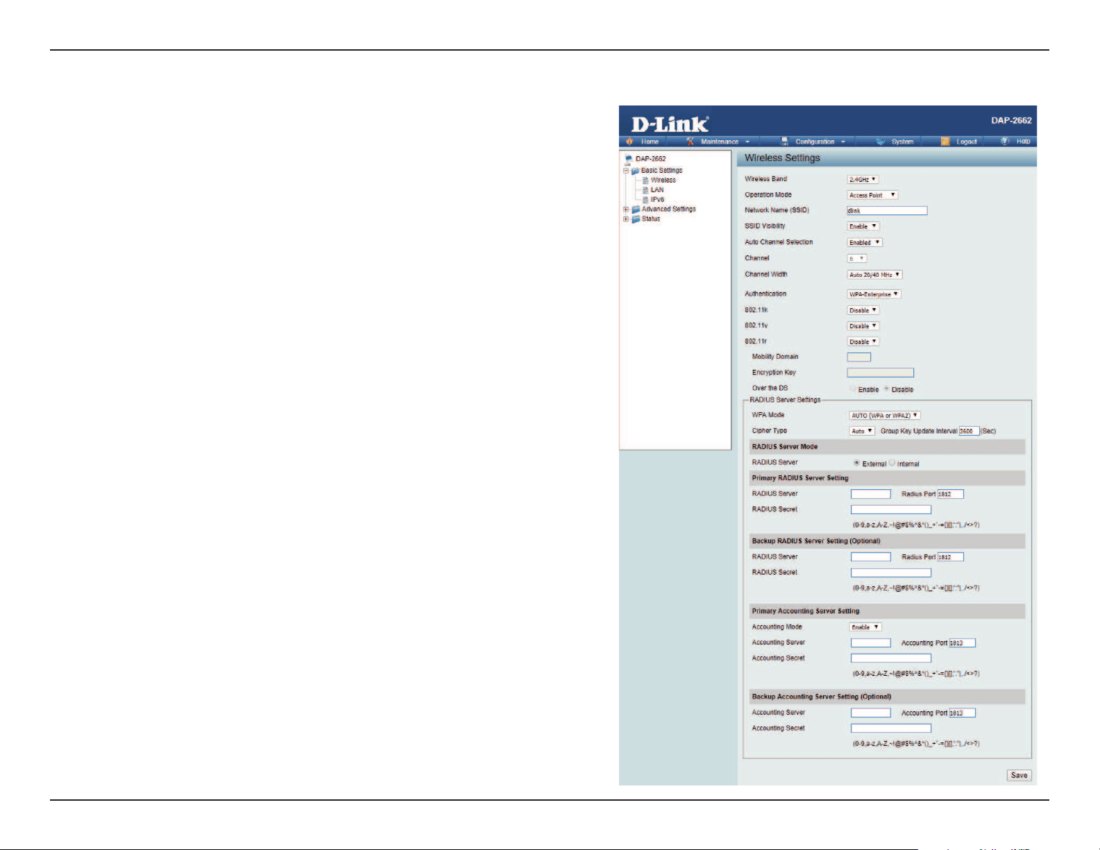
Wi-Fi Protected Access (WPA / WPA2)
WPA was created by the Wi-Fi Alliance to address the limitations and weaknesses found in WEP. This protocol is mainly based on the 802.11i standard.
There are also two variations found in WPA called WPA-Personal (PSK) and WPA-Enterprise (EAP).
WPA-Enterprise requires the user to install a Radius Server on the network for authentication.
WPA-Personal does not require the user to install a Radius Server on the network.
Comparing WPA-PSK with WPA-EAP, WPA-PSK is seen as a weaker authentication but comparing WPA-PSK to WEP, WPA-PSK is far more secure than
WEP. WPA-EAP is the highest level of wireless security a user can use for wireless today.
WPA2 is an upgrade of WPA. WPA2 yet again solves some possible security issues found in WPA. WPA2 has two variations called WPA2-Personal (PSK)
and WPA2-Enterprise (EAP) which is the same as found with WPA.
WPA Mode:
Cipher Type:
Group Key Update:
Pass Phrase:
When WPA-Personal is selected for Authentication type,
you must also select a WPA mode from the drop-down
menu: AUTO (WPA or WPA2), WPA2 Only, or WPA Only.
WPA and WPA2 use dierent algorithms. AUTO (WPA or
WPA2) allows you to use both WPA and WPA2.
When you select WPA-Personal, you must also select AUTO,
AES, or TKIP from the pull down menu.
Select the interval during which the group key will be valid.
The default value of 1800 is recommended.
When you select WPA-Personal, please enter a Pass Phrase
in the corresponding eld.
Web User Interface
21
WPA Mode:
Cipher Type:
Group Key Update Interval:
Network Access Protection:
RADIUS Server:
RADIUS Port:
RADIUS Secret:
Account Server:
Account Port:
Account Secret:
When WPA-Enterprise is selected, you must also
select a WPA mode from the drop-down menu:
AUTO (WPA or WPA2), WPA2 Only, or WPA Only.
WPA and WPA2 use dierent algorithms. AUTO
(WPA or WPA2) allows you to use both WPA and
WPA2.
When WPA-Enterprise is selected, you must also
select a cipher type from the drop-down menu:
Auto, AES, or TKIP.
Select the interval during which the group key
will be valid. 1800 is the recommended value as
a lower interval may reduce data transfer rates.
Enable or disable Microsoft Network Access
Protection.
Enter the IP address of the RADIUS server.
Enter the RADIUS port.
Enter the RADIUS secret.
Enter the IP address of the Account Server.
Enter the Account port.
Enter the Account secret.
Web User Interface
22
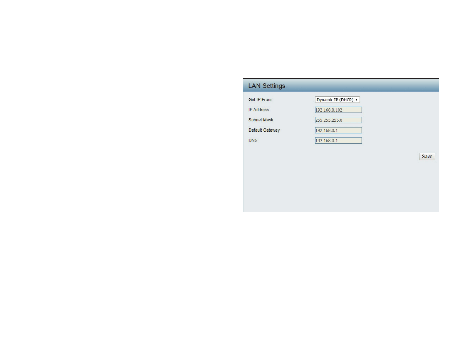
LAN
LAN is short for Local Area Network. This is considered your internal network. These are the IP settings of the LAN interface for the DAP-2662. These
settings may be referred to as private settings. You may change the LAN IP address if needed. The LAN IP address is private to your internal network
and cannot be seen on the Internet.
Get IP From:
IP Address:
Subnet Mask:
Default Gateway:
DNS:
Dynamic IP (DHCP) is chosen here. Choose this option if
you have a DHCP server in your network. When Dynamic
IP (DHCP) is selected, the other elds here will be grayed
out. Please allow about 2 minutes for the DHCP client to
be functional once this selection is made. If you wish to
assign a static IP address to the DAP-2662, choose Static
IP (Manual).
Assign a static IP address that is within the IP address
range of your network.
Enter the subnet mask. All devices in the network must
share the same subnet mask.
Enter the IP address of the gateway/router in your
network.
Enter a DNS server IP address. This is usually the local IP
address of your gateway/router.
Web User Interface
23
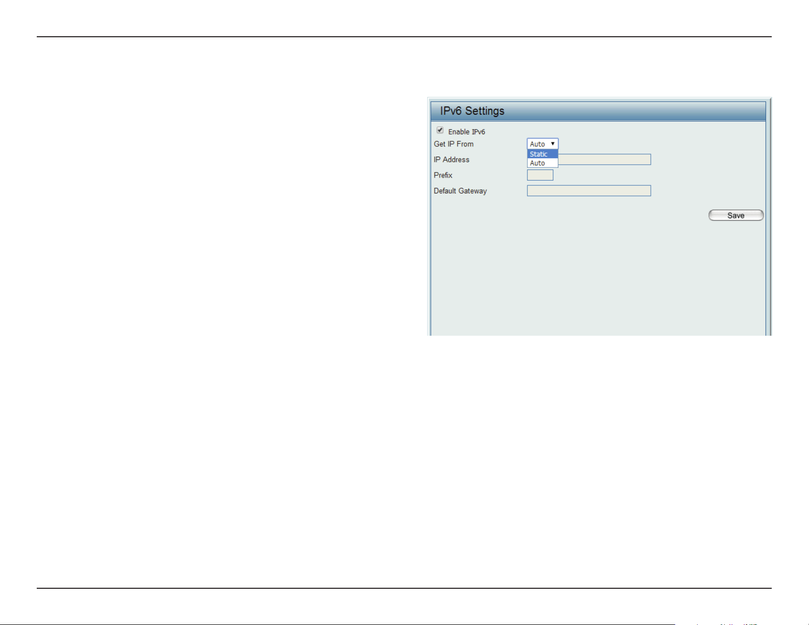
IPv6
Enable IPv6:
Get IP From:
IP Address:
Prex:
Default Gateway:
Check to enable the IPv6
Auto is chosen here. Choose this option the DAP-2662
can get IPv6 address automatically or use Static to set
IPv6 address manually.
Other elds here will be grayed out when Auto is selected.
Enter the LAN IPv6 address used here.
Enter the LAN subnet prex length value used here.
Enter the LAN default gateway IPv6 address used here.
Web User Interface
24
Advanced Settings
In the Advanced Settings Section users can congure advanced settings concerning Performance, Multiple SSID, VLAN, Security, Quality of Service, AP Array,
Web Redirection, DHCP Server, Filters and Scheduling. The following pages will explain settings found in the Advanced Settings section in more detail.
Web User Interface
25
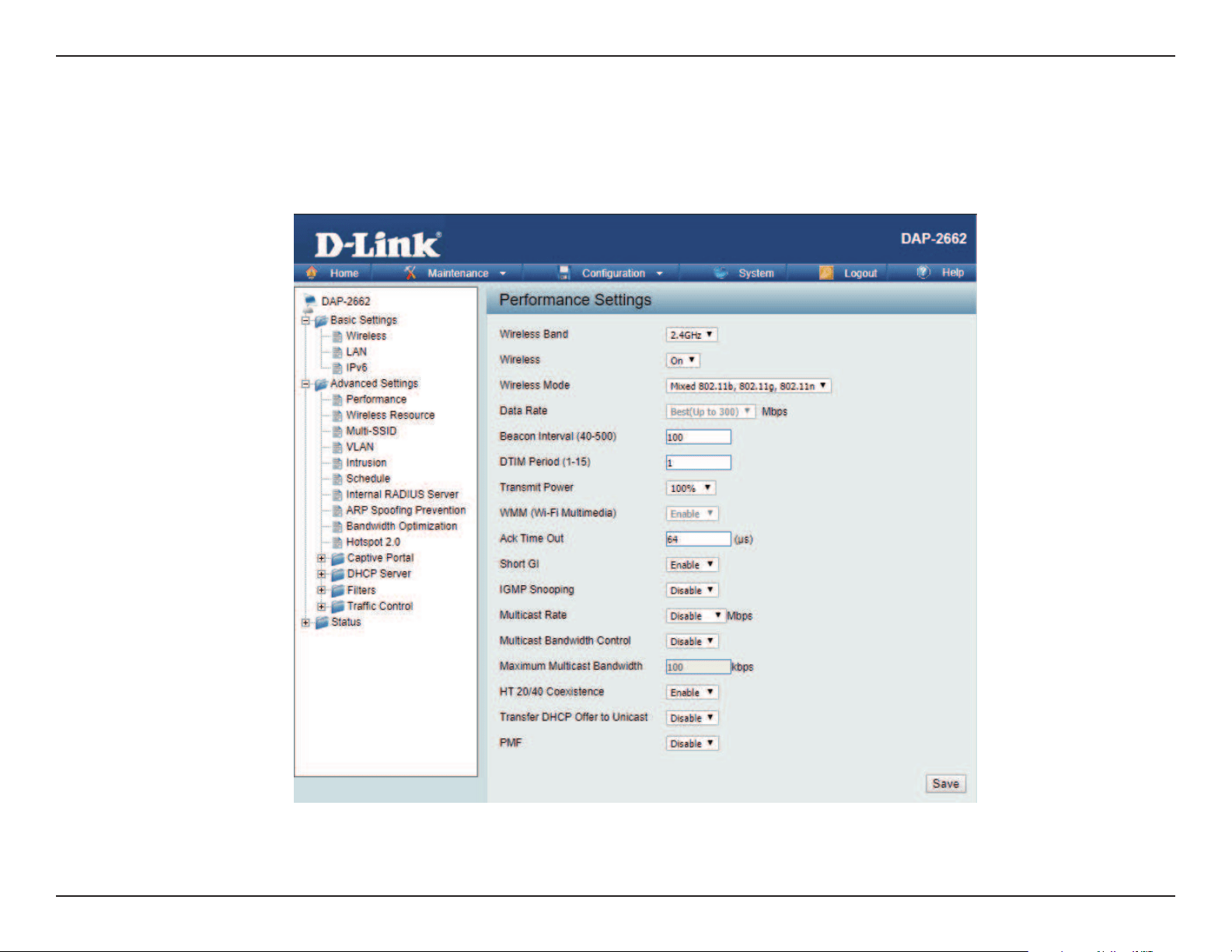
Performance
On the Performance Settings page users can congure more advanced settings concerning the wireless signal and hosting.
Wireless Band:
Wireless:
Wireless Mode:
Data Rate*:
Beacon Interval (40-
500):
DTM Interval (1-15):
Select either 2.4GHz or 5GHz.
Use the drop-down menu to turn the wireless function On or O.
The dierent combinations of clients that can be supported include
Mixed 802.11n, 802.11g and 802.11b, Mixed 802.11g and 802.11b
and 802.11n Only in the 2.4 GHz band and Mixed 802.11n, 802.11a,
802.11a only, and 802.11n Only in the 5 GHz band. Please note that
when backwards compatibility is enabled for legacy (802.11a/g/b)
clients, degradation of 802.11n (draft) wireless performance is
expected.
Indicate the base transfer rate of wireless adapters on the wireless
LAN. The AP will adjust the base transfer rate depending on the base
rate of the connected device. If there are obstacles or interference, the
AP will step down the rate. This option is enabled in Mixed 802.11g
and 802.11b mode (for 2.4 GHz) and 802.11a only mode (for 5 GHz).
The choices available are Best (Up to 54), 54, 48, 36, 24, 18, 12, 9, 6
for 5 GHz and Best (Up to 54), 54, 48, 36, 24, 18, 12, 9, 6, 11, 5.5, 2 or
1 for 2.4 GHz.
Beacons are packets sent by an access point to synchronize a
wireless network. Specify a value in milliseconds. The default (100)
is recommended. Setting a higher beacon interval can help to save
the power of wireless clients, while setting a lower one can help a
wireless client connect to an access point faster.
Select a Delivery Trac Indication Message setting between 1 and 15. 1 is the default setting. DTIM is a countdown informing
clients of the next window for listening to broadcast and multicast messages.

Web User Interface
26
Transmit Power:
WMM (Wi-Fi
Multimedia):
Ack Time Out
(2.4 GHZ, 64~200):
Short GI:
IGMP Snooping:
Multicast Rate:
Multicast Bandwidth
Control :
Maximum Multicast
Bandwidth :
HT20/40 Coexistence :
Transfer DHCP Oer
to Unicast :
PMF:
This setting determines the power level of the wireless transmission. Transmitting power can be adjusted to eliminate the
overlapping of wireless area coverage between two access points where interference is a major concern. For example, if wireless
coverage is intended for half of the area, then select 50% as the option. Use the drop-down menu to select 100%, 50%, 25%, or
12.5%.
WMM stands for Wi-Fi Multimedia. Enabling this feature will improve the user experience for audio and video applications over
a Wi-Fi network.
To eectively optimize throughput over long distance links enter a value for Acknowledgement Time Out between 25 and 200
microseconds for 5 GHz or from 64 to 200 microseconds in the 2.4 GHz in the eld provided.
Select Enable or Disable. Enabling a short guard interval can increase throughput. However, be aware that it can also increase
the error rate in some installations due to increased sensitivity to radio-frequency installations.
Select Enable or Disable. Internet Group Management Protocol allows the AP to recognize IGMP queries and reports sent between
routers and an IGMP host (wireless STA). When IGMP snooping is enabled, the AP will forward multicast packets to an IGMP host
based on IGMP messages passing through the AP.
Adjust the multicast packet data rate here. The multicast rate is supported in AP mode, (2.4 GHZ and 5 GHZ) and WDS with AP
mode, including Multi-SSIDs.
Adjust the multicast packet data rate here. The multicast rate is supported in AP mode, and WDS with AP mode, including Multi-
SSIDs
Set the multicast packets maximum bandwidth pass through rate from the Ethernet interface to the Access Point.
Enable this option to reduce interference from other wireless networks in your area. If the channel width is operating at 40MHz
and there is another wireless network’s channel over-lapping and causing interference, the Access Point will automatically change
to 20MHz.
Enable to transfer the DHCP Oer to Unicast from LAN to WLAN, suggest to enable this function if stations number is larger than 30.
Enable this option to help protect clients against forged management frames spoofed from other devices that might otherwise
disrupt a valid user session.
Web User Interface
27
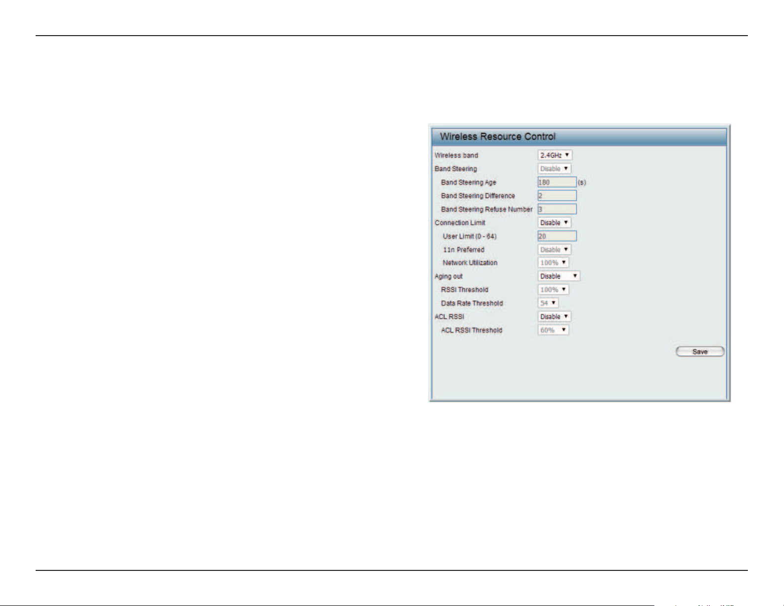
Wireless Resource Control
The Wireless Resource Control window is used to congure the wireless connection settings so that the device can detect the best wireless con-
nection in your environment.
Airtime Fairness:
Wireless band:
Band Steering:
Band Steering Age:
Band Steering
Dierence:
Band Steering
Refuse Number:
Connection Limit:
Enable airtime fairness to help regulate downlink
airtime.
Select 2.4GHz or 5GHz.
Use the drop-down menu to Enable the 5G Preferred
function. When the wireless clients support both
2.4GHz and 5GHz and the 2.4GHz signal is not strong
enough, the device will use 5G as higher priority.
Enter the time in seconds to specify the interval of
updating information.
The 5G preferred dierence value is equal to the
number of 5GHz wireless client connections minus
the number of 2.4GHz wireless client connections.
If the number of 5GHz wireless client connections
minus the number of 2.4GHz wireless client connec-
tions exceed this value, the extra 5GHz wireless client
connections will be forced to connect to the 2.4GHz
band and not the 5GHz band.
Enter the maximum 5G connection attempts allowed before the 5G preferred function will be disabled for the wireless
station connection.
Select Enable or Disable. This is an option for load balancing. This determines whether to limit the number of users
accessing this device. The exact number is entered in the User Limit eld below. This feature allows the user to share the
wireless network trac and the client using multiple APs. If this function is enabled and when the number of users ex-
ceeds this value, or the network utilization of this AP exceeds the percentage that has been specied, the DAP-2662 will
not allow clients to associate with the AP.

Web User Interface
28
User Limit:
11n Preferred:
Network Utilization:
Aging out:
RSSI Threshold:
Data Rate Threshold:
ACL RSSI:
ACL RSSI Threshold:
Set the maximum amount of users that are allowed access (zero to 64 users) to the device using the specied wireless
band. The default setting is 20.
Use the drop-down menu to Enable the 11n Preferred function. The wireless clients with 802.11n protocol will have
higher priority to connect to the device.
Set the maximum utilization of this access point for service. The DAP-2662 will not allow any new clients to associate
with the AP if the utilization exceeds the value the user species. Select a utilization percentage between 100%, 80%,
60%, 40%, 20%, or 0%. When this network utilization threshold is reached, the device will pause one minute to allow net-
work congestion to dissipate.
Use the drop-down menu to select the criteria of disconnecting the wireless clients. Available options are RSSI and Data
Rate.
When RSSI is selected in the Aging out drop-down menu, select the percentage of RSSI here. When the RSSI of wireless
clients is lower than the specied percentage, the device disconnects the wireless clients.
When Data Rate is selected in the Aging out drop-down menu, select the threshold of data rate here. When the data
rate of wireless clients is lower than the specied number, the device disconnects the wireless clients.
Use the drop-down menu to Enable the function. When enabled, the device denies the connection request from the
wireless clients with the RSSI lower than the specied threshold below.
Set the ACL RSSI Threshold.
Web User Interface
29
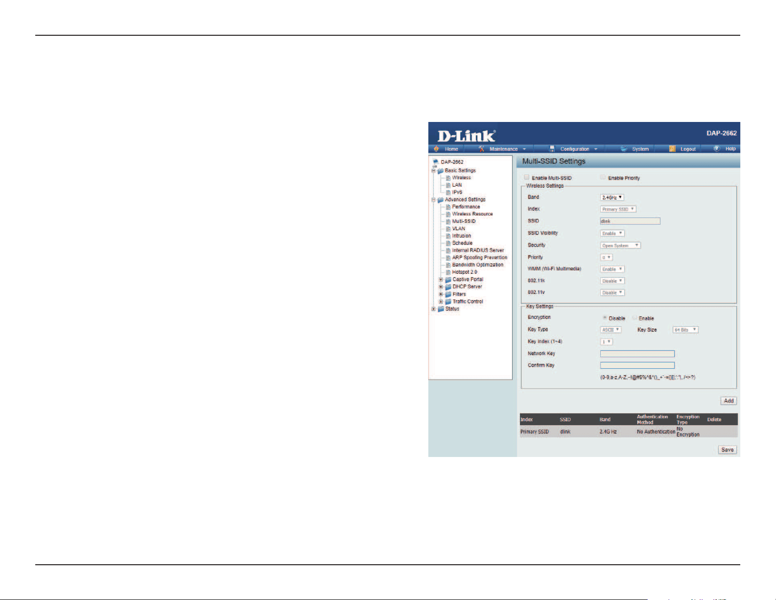
Multi-SSID
This device supports up to four multiple Service Set Identiers. You can set the Primary SSID under Basic > Wireless. The SSID’s factory default setting
is dlink. The SSID can be easily changed to connect to an existing wireless network or to establish a new wireless network.
Enable Multi-
SSID:
Enable Priority:
Band:
Index:
SSID:
SSID Visibility:
Security:
Priority:
WMM (Wi-Fi
Multimedia):
Check to enable support for multiple SSIDs.
Check to enable support for SSID priority level.
Select 2.4GHz or 5GHz.
You can select up to seven multi-SSIDs. With the Primary
SSID, you have a total of eight multi-SSIDs.
Service Set Identier (SSID) is the name designated for a
specic wireless local area network (WLAN). The SSID’s
factory default setting is dlink. The SSID can be easily
changed to connect to an existing wireless network or to
establish a new wireless network.
Enable or Disable SSID visibility. Enabling this feature
broadcasts the SSID across the network, thus making it
visible to all network users.
The Multi-SSID security can be Open System, WPA-
Personal, or WPA-Enterprise. For a detailed description of
the Open System parameters please go to page 23. For
a detailed description of the WPA-Personal parameters
please go to page 24. For a detailed description of the
WPA-Enterprise parameters please go to page 25.
Select the priority level of the SSID selected.
WMM stands for Wi-Fi Multimedia. Enabling this feature
will improve the user experience for audio and video
applications over a Wi-Fi network.

Web User Interface
30
Encryption:
Key Type:
Key Size:
Key Index (1-4):
Key:
WPA Mode:
Cipher Type:
Group Key Update Interval:
Pass Phrase:
Conrm Pass Phrase:
RADIUS Server:
RADIUS Port:
RADIUS Secret:
When you select Open System, toggle between Enable and Disable. If Enable is selected, the Key Type, Key Size, Key Index
(1~4), Key, and Conrm Keys must also be congured.
Select HEX or ASCII.
Select 64-bit or 128-bit.
Select from the 1st to 4th key to be set as the active key.
Input up to four keys for encryption. You will select one of these keys in the Key Index drop-down menu.
When you select either WPA-Personal or WPA-Enterprise, you must also choose a WPA mode from the drop-down menu: AUTO
(WPA or WPA2), WPA2 Only, or WPA Only. WPA and WPA2 use dierent algorithms. AUTO (WPA or WPA2) allows you to use both
WPA and WPA2. In addition, you must congure Cipher Type, and Group Key Update Interval.
Select Auto, AES, or TKIP from the drop-down menu.
Select the interval during which the group key will be valid. The default value of 1800 seconds is recommended.
When you select WPA-Personal, please enter a Pass Phrase in the corresponding eld.
When you select WPA-Personal, please re-enter the Pass Phrase entered in the previous item in the corresponding eld.
When you select WPA-Enterprise, enter the IP address of the RADIUS server. In addition, you must congure RADIUS Port and
RADIUS Secret.
Enter the RADIUS port.
Enter the RADIUS secret.
Web User Interface
31
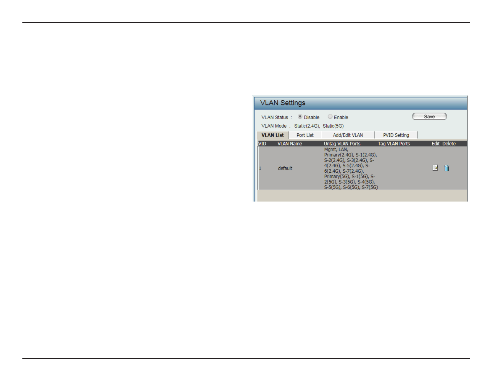
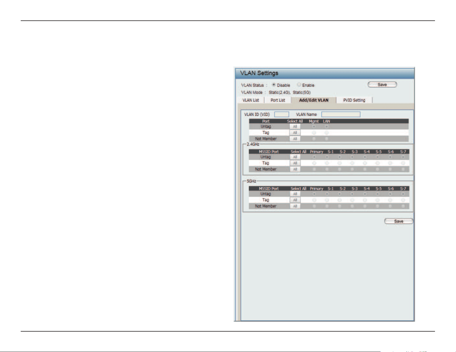
VLAN
The DAP-2662 supports VLANs. VLANs can be created with a Name and VID. Mgmt (TCP stack), LAN, Primary/Multiple SSID, and WDS connection
can be assigned to VLANs as they are physical ports. Any packet which enters the DAP-2662 without a VLAN tag will have a VLAN tag inserted with
a PVID. The VLAN List tab displays the current VLANs.
VLAN Status:
VLAN Mode:
Use the radio button to toggle to Enable. Next,
go to the Add/Edit VLAN tab to add or modify
an item on the VLAN List tab.
The current VLAN mode is displayed.
VLAN List
Web User Interface
32
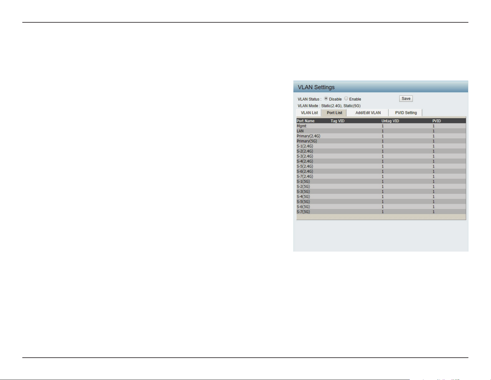
The Port List tab displays the current ports. If you want to congure the guest and internal networks on a Virtual LAN (VLAN), the switch and DHCP
server you are using must also support VLANs. As a prerequisite step, congure a port on the switch for handling VLAN tagged packets as described
in the IEEE 802.1Q standard.
VLAN Status:
Port Name:
Tag VID:
Untag VID:
PVID:
Use the radio button to toggle to Enable. Next, go to the Add/Edit
VLAN tab to add or modify an item on the VLAN List tab.
The name of the port is displayed in this column.
The Tagged VID is displayed in this column.
The Untagged VID is displayed in this column.
The Port VLAN Identier is displayed in this column.
Port List
Web User Interface
33
The Add/Edit VLAN tab is used to congure VLANs. Once you have made the desired changes, click Save to have your changes take eect.
VLAN Status:
VLAN ID:
VLAN Name:
Use the radio button to toggle to Enable.
Provide a number between 1 and 4094
for the Internal VLAN.
Enter the VLAN to add or modify.
Add/Edit VLAN
Web User Interface
34
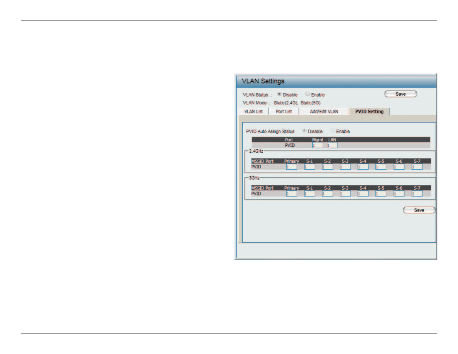
The PVID Setting tab is used to enable/disable the Port VLAN Identier Auto Assign Status as well as to congure various types of PVID settings.
Click Save button to have your changes take eect.
VLAN Status:
PVID Auto Assign Status:
Use the radio button to toggle between
Enable and Disable.
Use the radio button to toggle PVID auto
assign status to Enable.
PVID Settings
Web User Interface
35
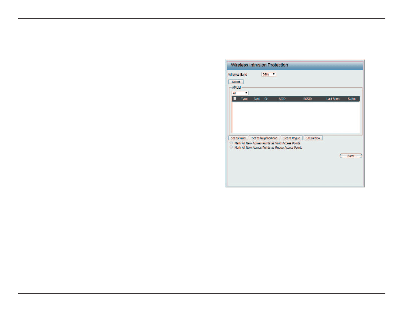
Intrusion
The Wireless Intrusion Protection window is used to classify APs as Valid, Neighborhood, Rogue, or a New group. Click Save for the changes to take
eect.
Wireless Band: Click the drop-down menu to select the wireless
band, 2.4GHz or 5GHz.
Detect: Click Detect to initiate a scan of the network.
AP List: Click the drop-down menu to select All, Valid,
Neighbor, Rogue, and New.
The following is a denition of the listed AP cat-
egories:
y Valid: An AP which is authenticated to the net-
work with encryption is classied as valid.
y Neighbor: A detected AP with a weak signal
strength is classied as a suspect neighbor.
y Rogue: An AP that has been installed on the
secure network without explicit authorization.
y New: An alternative category.
From the AP List select a detected AP and click
Set as Valid, Set as Neighborhood, Set as Rogue,
or Set as New to manually dene the category
type for the AP. Alternatively, click the radio but-
ton to mark all new access points as valid or
rogue.
Web User Interface
36
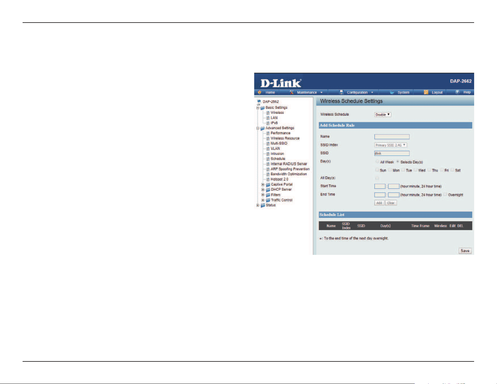
Schedule
The Wireless Schedule Settings window is used to add and modify scheduling rules on the device. Click Save for your changes to take eect.
Wireless Schedule:
Name:
Index:
SSID:
Day(s):
All Day(s):
Start Time:
End Time:
Use the drop-down menu to enable the device’s
scheduling feature.
Enter a name for the new scheduling rule in the eld
provided.
Use the drop-down menu to select the desired SSID.
This read-only eld indicates the current SSID in use. To
create a new SSID, go to the Wireless Settings window
(Basic Settings > Wireless).
Toggle the radio button between All Week and Select
Day(s). If the second option is selected, check the
specic days you want the rule to be eective on.
Check this box to have your settings apply 24 hours
a day.
Enter the beginning hour and minute, using a 24-hour
clock.
Enter the ending hour and minute, using a 24-hour
clock.
Web User Interface
37
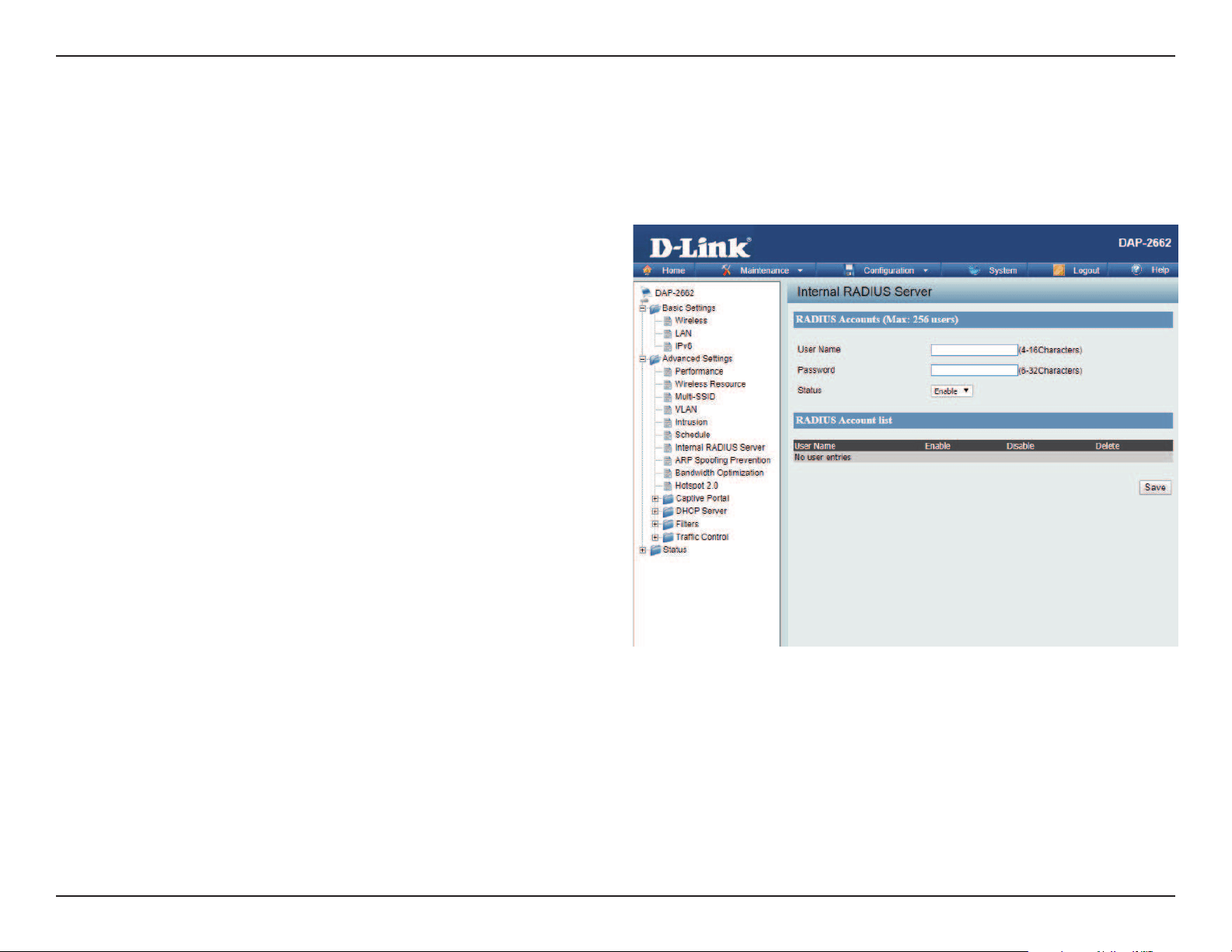
Internal RADIUS Server
The DAP-2662 features a built-in RADIUS server. Once you have nished adding a RADIUS account, click the Save to have your changes take eect.
The newly-created account will appear in this RADIUS Account List. The radio buttons allow the user to enable or disable the RADIUS account. Click
the icon in the delete column to remove the RADIUS account. We suggest you limit the number of accounts to below 30.
User Name:
Password:
Status:
RADIUS Account List:
Enter a name to authenticate user access to the
internal RADIUS server.
Enter a password to authenticate user access to the
internal RADIUS server. The length of your password
should be 8~64.
Toggle the drop-down menu between Enable and
Disable.
Displays the list of users.
Web User Interface
38
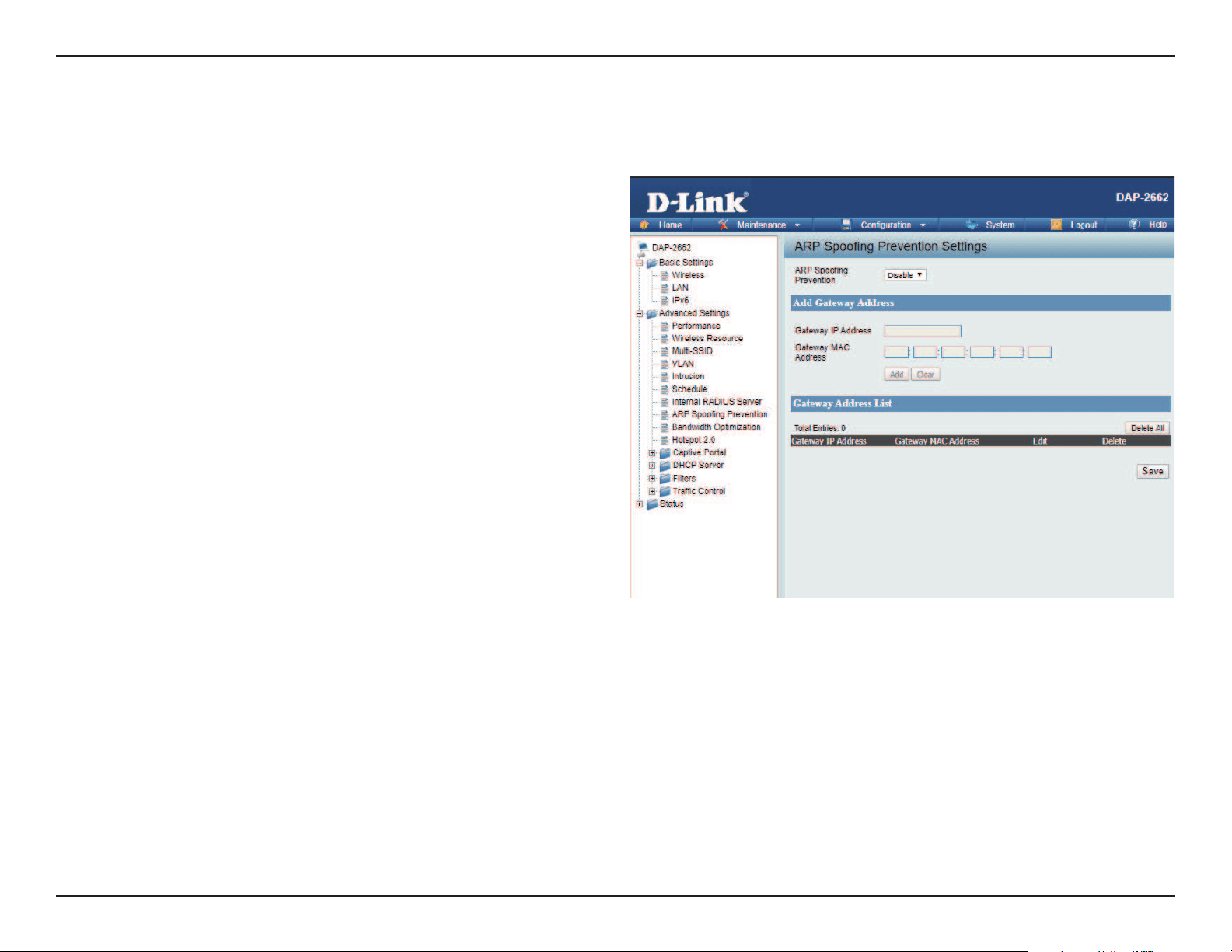
ARP Spoong Prevention
The ARP Spoong Prevention feature allows users to add IP/MAC address mapping to prevent ARP Spoong attack.
ARP Spoong Prevention:
Gateway IP Address:
Gateway MAC Address:
This check box allows you to enable the ARP
Spoong prevention function.
Enter a gateway IP address.
Enter a gateway MAC address.
Web User Interface
39
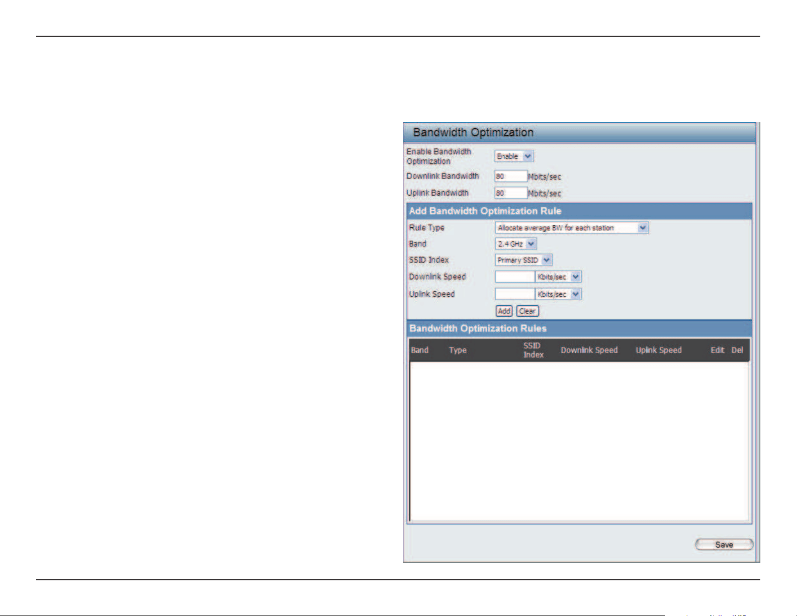
Bandwidth Optimization
The Bandwidth Optimization window allows the user to manage the bandwidth of the device and arrange the bandwidth for various wireless clients.
When the Bandwidth Optimization rule is nished, click the Add button. To discard the Add Bandwidth Optimization Rule settings, click the Clear
button. Click Save button to have your changes take eect.
Enable Bandwidth
Optimization:
Downlink Bandwidth:
Uplink Bandwidth:
Allocate average BW
for each station:
Allocate maximum BW
for each station:
Allocate dierent BW
for a/b/g/n stations:
Allocate specic BW
for SSID:
Rule Type:
Use the drop-down menu to Enable the Bandwidth
Optimization function.
Enter the downlink bandwidth of the device in
Mbits per second.
Enter the uplink bandwidth of the device in Mbits
per second.
AP will distribute the average bandwidth for each
client.
Specify the maximum bandwidth for each
connected client. Reserve certain bandwidth for
future clients.
The weight of 11b/g/n and 11a/n client are
10%/20%/70% ; 20%/80%. AP will distribute
dierent bandwidth for 11a/b/g/n clients.
All clients share the total bandwidth.
Use the drop-down menu to select the type
that is applied to the rule. Available options are:
Allocate average BW for each station, Allocate
maximum BW for each station, Allocate
dierent BW for 1a/b/g/n stations, and Allocte
specic BW for SSID.

Web User Interface
40
Band:
SSID Index:
Downlink Speed:
Uplink Speed:
Use the drop-down menu to toggle the wireless band between 2.4GHz and 5GHz.
Use the drop-down menu to select the SSID for the specied wireless band.
Enter the download speed limit in either Kbits/sec or Mbits/sec for the rule.
Enter the upload speed limit in either Kbits/sec or Mbits/sec for the rule.
Web User Interface
41
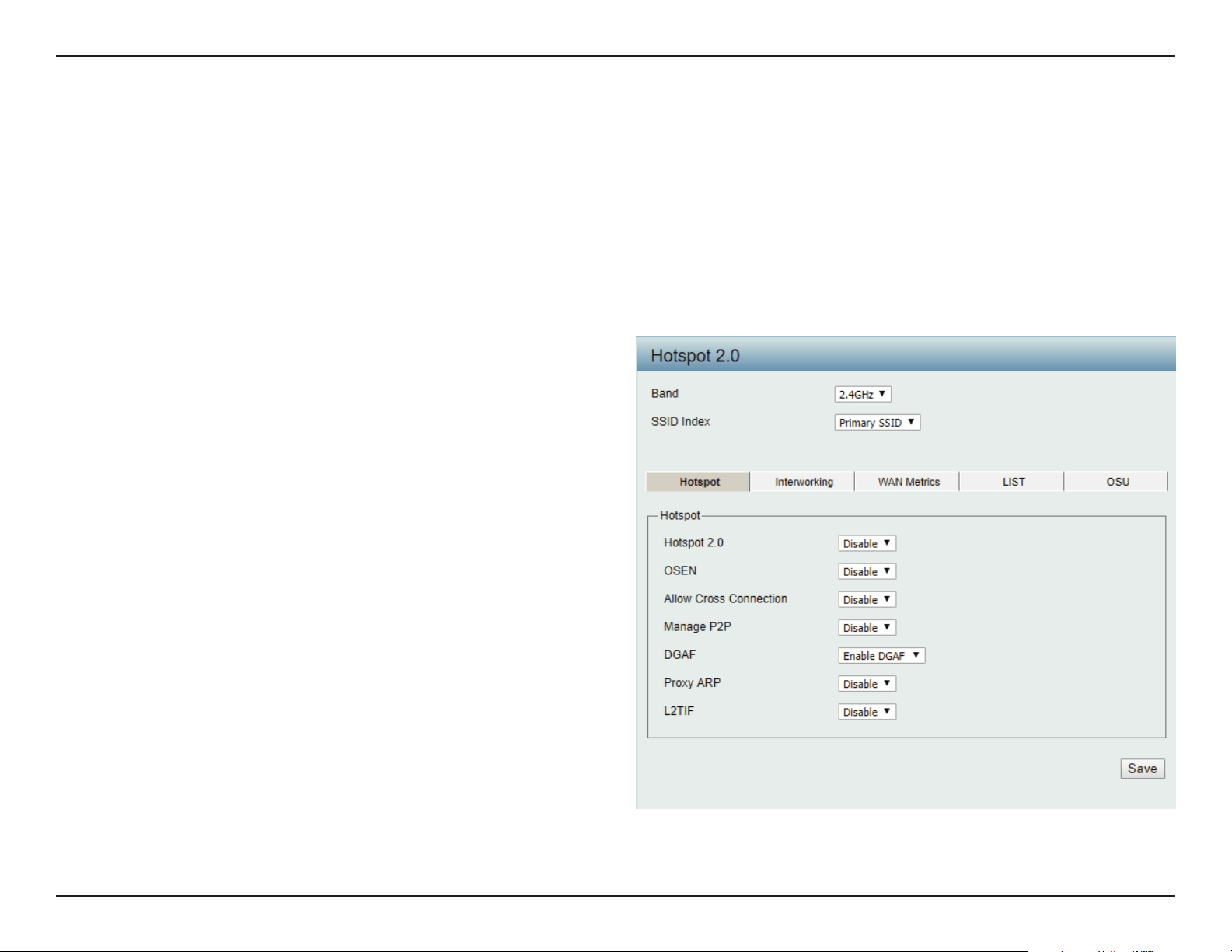
Hotspot 2.0
Hotspot 2.0 (HS2) is a new networking standard designed to make the process of connecting to public wireless hotspots easier and more secure
with seamless authentication and encryption between your device and access points. This is based on the IEEE 802.11u standard and uses WPA2-
Enterprise for authentication between clients and access points.
Band: Specify Either 2.4 GHz or 5 GHz from the drop down list.
SSID Index: Specify from drop down list the SSID index.
Hotspot 2.0:
OSEN:
Allow Cross
Connection:
Manage P2P:
DGAF:
Proxy ARP:
L2TIF:
Choose enable to turn on hotspot 2.0 function.
Enable OSU Server-only authenticated layer-2
Encryption Network (OSEN) to indicate that the
hotspot uses a OSEN network type.
Choose enable to allow cross connection for
clients.
Choose enable to allow P2P.
This option congures the Downstream Group
Addressed Forwarding. Choose enable to
allow AP to forward downstream group-
addressed frames.
Choose enable to allow proxy ARP.
Choose enable to allow Layer 2 Traffic
Inspection and Filtering.
Hotspot
Web User Interface
42
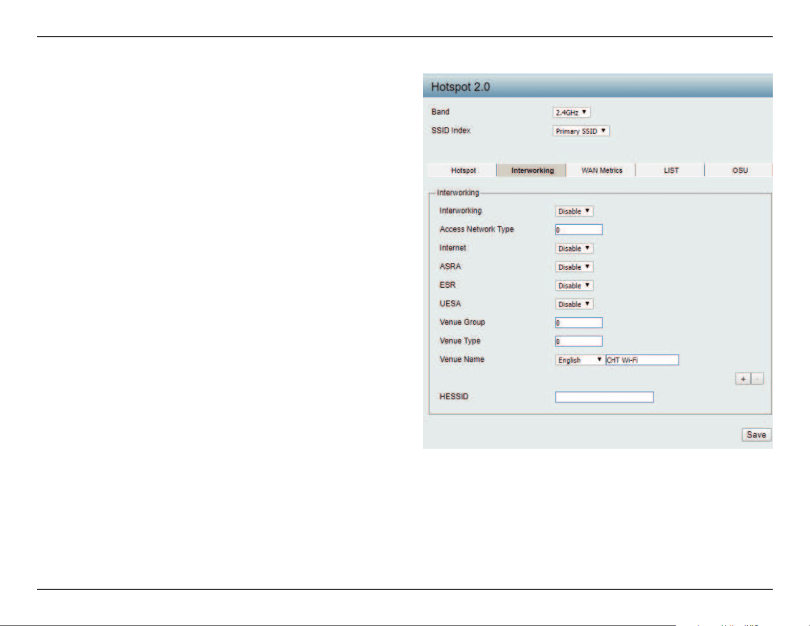
Interworking:
Access Network Type:
Internet:
ASRA:
ESR:
Venue Group:
Venue Type:
Venue Name:
HESSID:
Choose enable to turn on interworking
function.
Specify type of network.
Choose to enable or disable Internet access for
this network.
Choose enable if the network has Additional
Steps required for Access.
Choose enable to indicate that emergency
services are reachable through this device.
Specify group venue belongs to.
Specify type of venue.
Specify name of venue. Choose from the drop
down list a language used in the name.
Specify a homogenous extended service set
(ESS) ID that can be used to identify a specic
service provider network.
Interworking
Web User Interface
43
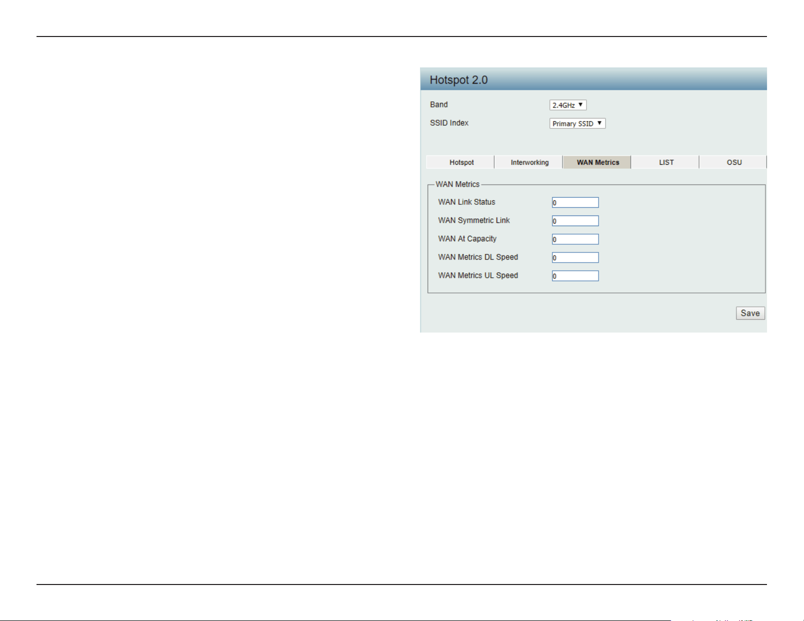
WAN Link Status:
WAN Symmetric Link:
WAN At Capacity:
WAN Metrics DL Speed:
WAN Metrics UL Speed:
Information about the status of the Access
Point’s WAN connection.
Set to 1 if the WAN link is symmetric (upload
and download speeds are the same), or set to
0 if not.
Set to 1 if the Access Point or the network is at
its max capacity, or set to 0 if not.
The downlink speed of the WAN connection
set in kbps. If the downlink speed is not known,
set to 0.
The uplink speed of the WAN connection set in
kbps. If the uplink speed is not known set to 0.
WAN Metrics
Web User Interface
44
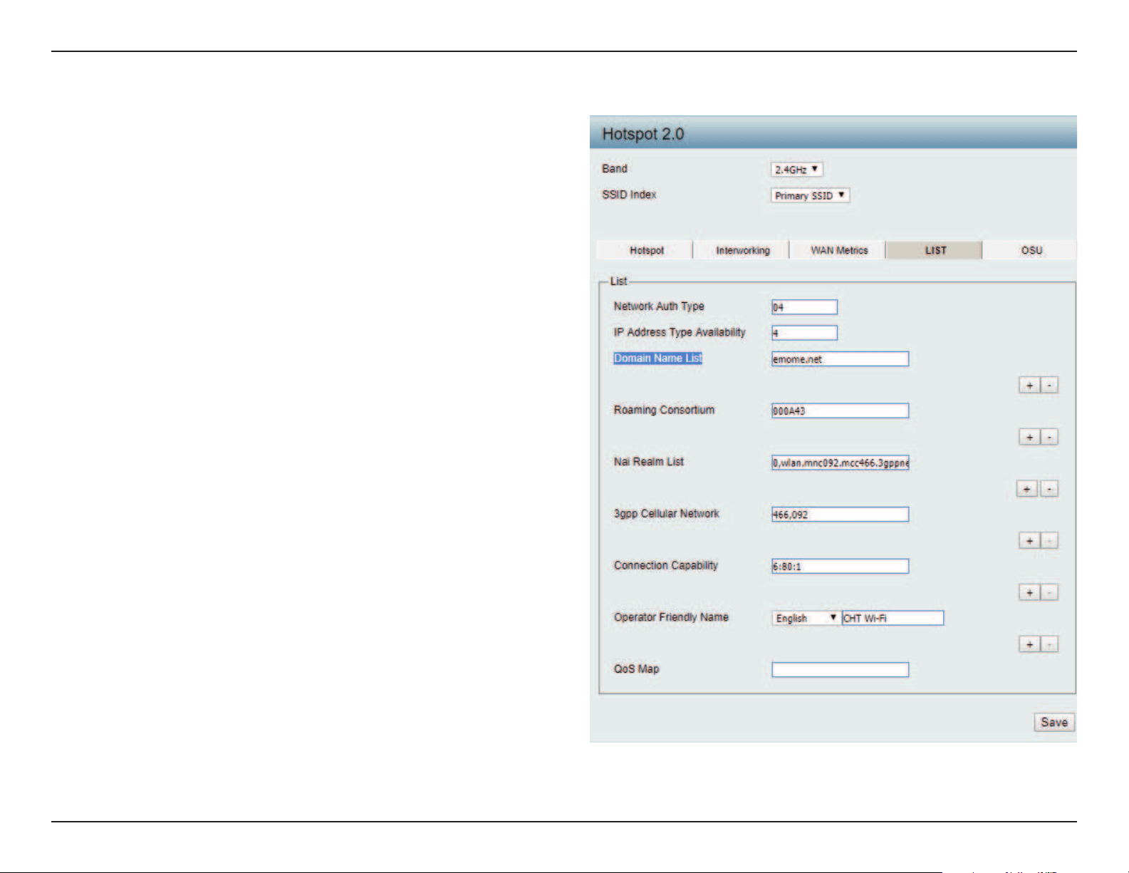
Network Auth Type:
IP Address Type
Avilability:
Domain Name List:
Roaming Consortium:
Nai Realm List:
3gpp Cellular Network:
Connection Capability:
Operator Friendly
Name:
QoS Map:
Identies whether this is an unsecured network.
Identifies IP address version and type that
the Hotspot Operator uses and that would be
allocated and available to a mobile device after
it authenticates to the network.
List one or more domain names for the entity
operating the AP.
Identifies service providers or groups of
roaming partners whose security credentials
can be used to connect to a network.
List of all NAI realms available through the BSS.
Identies the 3GPP cellular networks available
through the AP.
Identifies the availability of common IP
protocols (TCP, UDP, IPsec) and ports (21, 80,
443, 5060).
Identies the Hotspot venue operator.
Bit set to indicate support for QoS mapping
from 802.11 to external networks.
LIST
Web User Interface
45
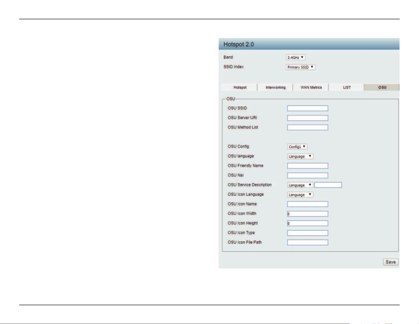
OSU SSID:
OSU Server URI:
OSU Method List:
OSU Cong:
OSU language:
OSU Friendly Name:
OSU Nai:
OSU Service
Description:
OSU Icon Language:
Specify the SSID that the device will associate
and connect to when accessing the
OSU server.
Specify the Uniform Resource Identier (URI)
of the OSU Server.
Spcify preferred list of encoding methods that
the OSU server supports in order of priority.
Choose from drop down list which conguration
set to use.
Choose from drop down list language to use.
Specify a list of one or more names in dierent
languages which will allow the device to
display the OSU Friendly Name in alternative
languages based on the language slected in
the setting of the mobile device.
Specify OSU Network Access Identier.
Choose the service description lagnuage from
drop down list. Specify the service provider’s
descrption of service oering.
Choose icon language from drop down list.
OSU

Web User Interface
46
OSU Icon Name:
OSU Icon Width:
OSU Icon Height:
OSU Icon Type:
OSU Icon File Path:
Specify icon name.
Specify width of the icon, in pixels.
Spcify length of the icon, in pixels.
Speciy icon le type, where the icon type is any mim-type
graphic format.
Specify location of icon le.
Web User Interface
47
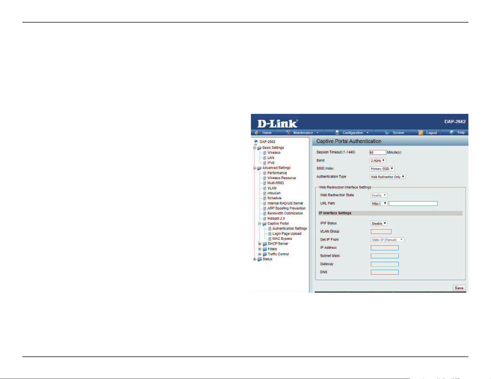
Captive Portal
The Captive Portal is a built-in web authentication server. When a station connects to an AP, the web browser will be redirected to a web authentication
page. In this window, user can view and congure the Captive Portal settings. After selecting Web Redirection Only as the Authentication Type, we
can congure the redirection website URL that will be applied to each wireless client in this network.
Authentication Settings-Web Redirection Only
Session
timeout(1-1440) :
Band :
SSID Index :
Authentication Type :
Web Redirection State :
URL Path :
IPIF Status :
VLAN Group :
Get IP From :
Enter the session timeout value here. This value can be from 1 to 1440 minutes. By default, this value is 60 minutes.
Select 2.4GHz or 5GHz.
Select the SSID for this Authentication.
Select the captive portal encryption type here.
Options to choose from are Web Redirection,
Username/Password, Passcode, Remote
RADIUS, LDAP and POP3. In this section we’ll
discuss the Web Redirection option.
Default setting is Enable when select Web
Redirection Only.
Select whether to use either HTTP or HTTPS
here. After selecting either http:// or https://,
enter the URL of the website that will be used
in the space provided.
Select to Enable or Disable the Captive Portal
with its IP interface feature here.
Enter the VLAN Group ID here.
Static IP (Manual) is chosen here. Choose this option if you do not have a DHCP server in your network, or if you wish to
assign a static IP address to the DAP-2662. When Dynamic IP (DHCP) is selected, the other elds here will be grayed out.
Please allow about 2 minutes for the DHCP client to be functional once this selection is made.

Web User Interface
48
IP Address :
Subnet Mask :
Gateway :
DNS :
Assign a static IP address that is within the IP address range of your network.
Enter the subnet mask. All devices in the network must share the same subnet mask.
Enter the IP address of the gateway/router in your network.
Enter a DNS server IP address. This is usually the local IP address of your gateway/router.
Web User Interface
49
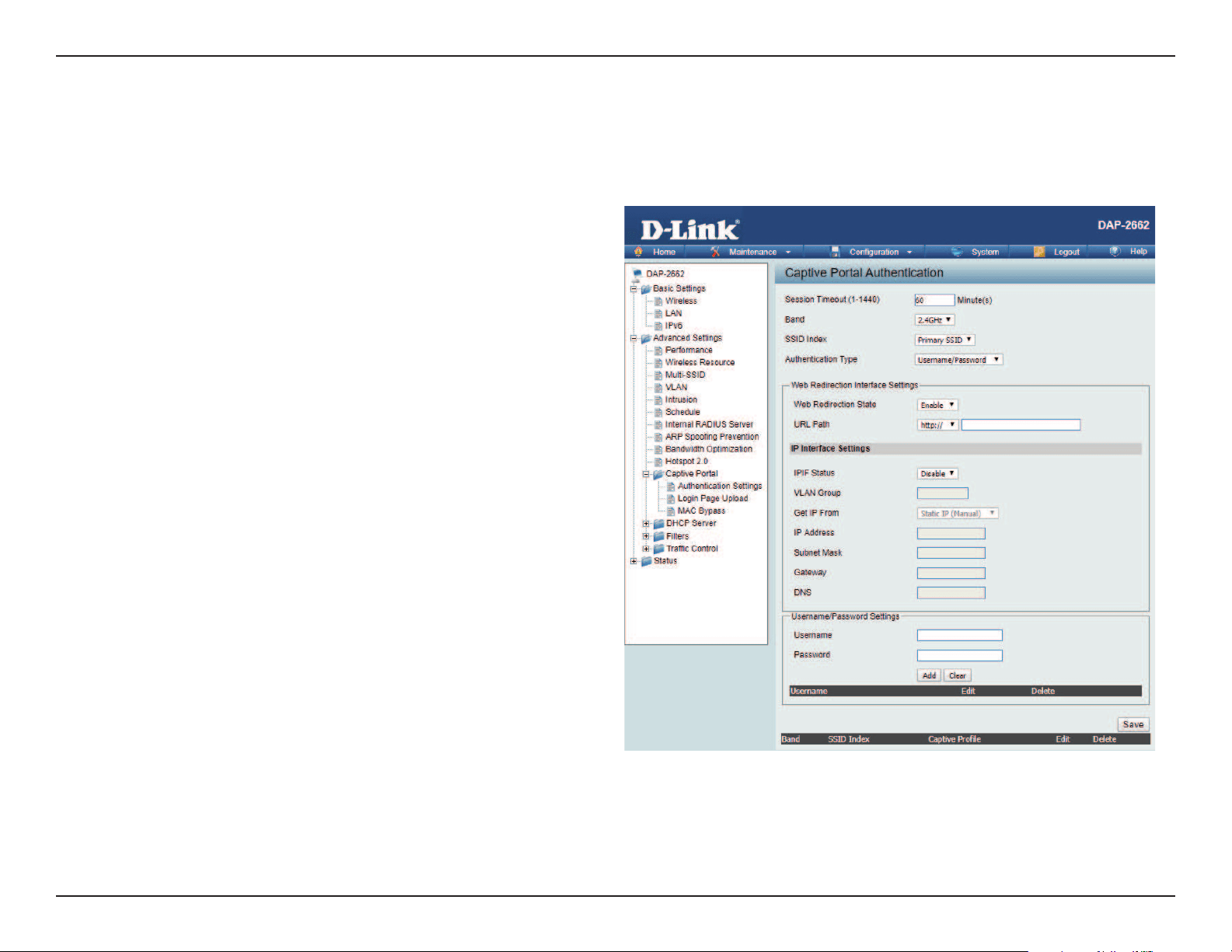
After selecting Username/Password as the Authentication Type, we can congure the Username/Password authentication that will be applied to
each wireless client in this network.
Authentication Settings- Username/Password
Session
timeout(1-1440) :
Band :
SSID Index :
Authentication Type :
Web Redirection State :
URL Path :
IPIF Status :
VLAN Group :
Get IP From :
Enter the session timeout value here. This value
can be from 1 to 1440 minutes. By default, this
value is 60 minutes.
Select 2.4GHz or 5GHz.
Select the SSID for this Authentication.
Select the captive portal encryption type here.
Options to choose from are Web Redirection,
Username/Password, Passcode, Remote
RADIUS, LDAP and POP3. In this section we’ll
discuss the Username/Password option.
Default is Disable or select Enable to enable the
website redirection feature.
Select whether to use either HTTP or HTTPS
here. After selecting either http:// or https://,
enter the URL of the website that will be used
in the space provided.
Select to Enable or Disable the Captive Portal
with its IP interface feature here.
Enter the VLAN Group ID here.
Static IP (Manual) is chosen here. Choose this
option if you do not have a DHCP server in
your network, or if you wish to assign a static IP
address to the DAP-2662. When Dynamic

Web User Interface
50
IP Address :
Subnet Mask :
Gateway :
DNS :
Username:
Password:
IP (DHCP) is selected, the other elds here will be grayed out. Please allow about 2 minutes for the DHCP client to be
functional once this selection is made.
Assign a static IP address that is within the IP address range of your network.
Enter the subnet mask. All devices in the network must share the same subnet mask.
Enter the IP address of the gateway/router in your network.
Enter a DNS server IP address. This is usually the local IP address of your gateway/router.
Enter the username for the new account here.
Enter the password for the new account here.
Web User Interface
51
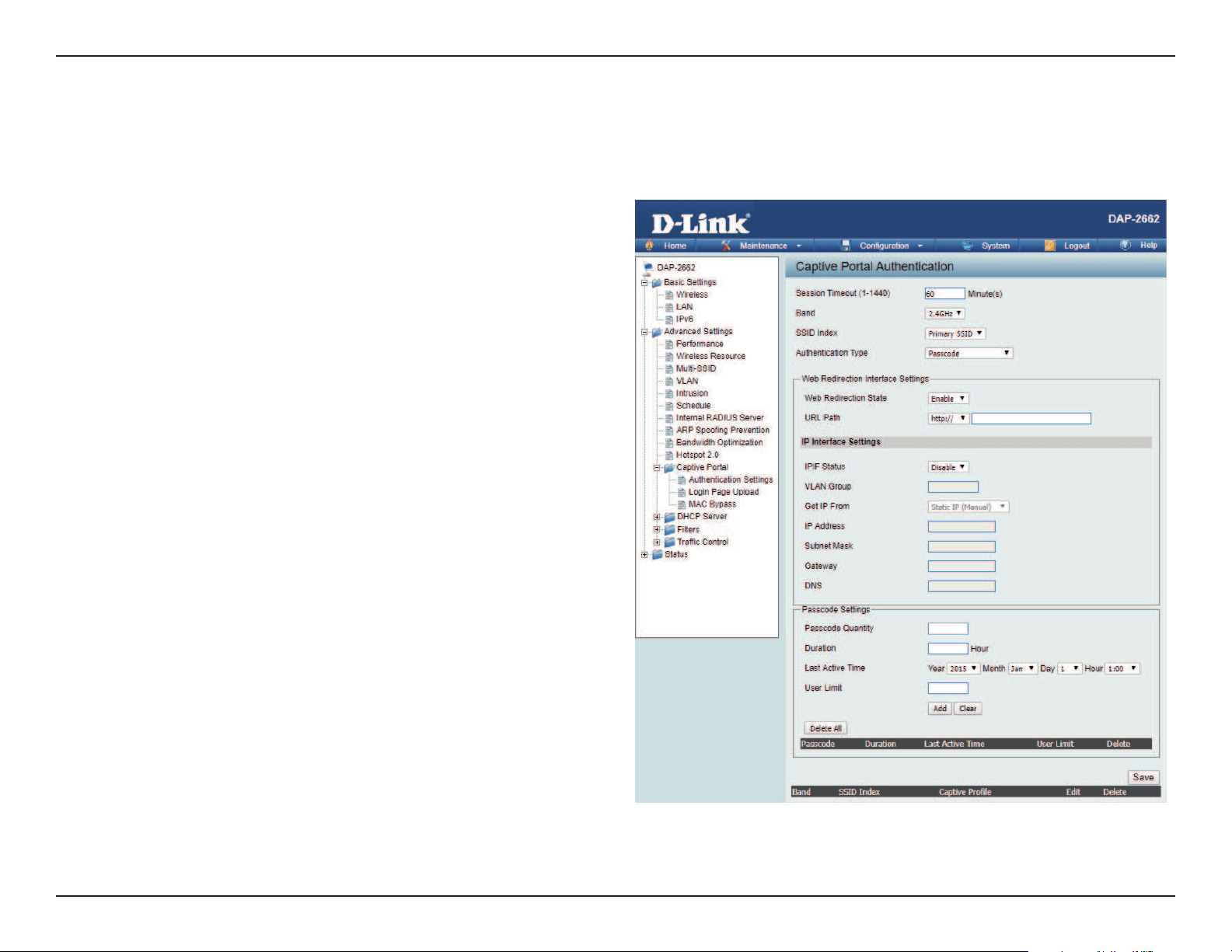
After selecting Passcode as the Authentication Type, we can congure the Passcode authentication that will be applied to each wireless client in
this network.
Authentication Settings- Passcode
Session
timeout(1-1440) :
Band :
SSID Index :
Authentication Type :
Web Redirection State :
URL Path :
IPIF Status :
VLAN Group :
Get IP From :
Enter the session timeout value here. This value
can be from 1 to 1440 minutes. By default, this
value is 60 minutes.
Select 2.4GHz or 5GHz.
Select the SSID for this Authentication.
Select the captive portal encryption type here.
Options to choose from are Web Redirection,
Username/Password, Passcode, Remote
RADIUS, LDAP and POP3. In this section we’ll
discuss the Passcode option.
Default is Disable or select Enable to enable the
website redirection feature.
Select whether to use either HTTP or HTTPS
here. After selecting either http:// or https://,
enter the URL of the website that will be used
in the space provided.
Select to Enable or Disable the Captive Portal
with its IP interface feature here.
Enter the VLAN Group ID here
Static IP (Manual) is chosen here. Choose this
option if you do not have a DHCP server in
your network, or if you wish to assign a static
IP address to the DAP-2662. When Dynamic IP
(DHCP) is selected, the other elds here will be

Web User Interface
52
IP Address :
Subnet Mask :
Gateway :
DNS :
Passcode Quantity:
Duration:
Last Active Day:
User Limit:
grayed out. Please allow about 2 minutes for the DHCP client to be functional once this selection is made.
Assign a static IP address that is within the IP address range of your network.
Enter the subnet mask. All devices in the network must share the same subnet mask.
Enter the IP address of the gateway/router in your network.
Enter a DNS server IP address. This is usually the local IP address of your gateway/router.
Enter the number of ticket that will be used here.
Enter the duration value, in hours, for this passcode.
Select the last active date for this passcode here. Year, Month and Day selections can be made.
Enter the maximum amount of users that can use this passcode at the same time
Web User Interface
53
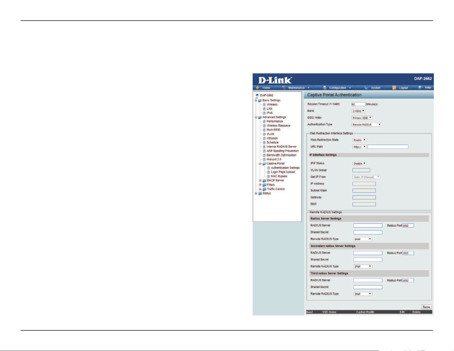
After selecting Remote RADIUS as the Authentication Type, we can congure the Remote RADIUS authentication that will be applied to each
wireless client in this network.
Authentication Settings- Remote RADIUS
Session
timeout(1-1440) :
Band :
SSID Index :
Authentication Type :
Web Redirection State :
URL Path :
IPIF Status :
VLAN Group :
Get IP From :
Enter the session timeout value here. This value can
be from 1 to 1440 minutes. By default, this value is 60
minutes.
Select 2.4GHz or 5GHz.
Select the SSID for this Authentication.
Select the captive portal encryption type here. Options
to choose from are Web Redirection, Username/
Password, Passcode, Remote RADIUS, LDAP and POP3.
In this section we’ll discuss the Remote RADIUS option.
Default is Disable or select Enable to enable the
website redirection feature.
Select whether to use either HTTP or HTTPS here. After
selecting either http:// or https://, enter the URL of the
website that will be used in the space provided.
Select to Enable or Disable the Captive Portal with its
IP interface feature here.
Enter the VLAN Group ID here
Static IP (Manual) is chosen here. Choose this option if
you do not have a DHCP server in your network, or if
you wish to assign a static IP address to the DAP-2662.
When Dynamic IP (DHCP) is selected, the other elds
here will be grayed out. Please allow about 2 minutes
for the DHCP client to be functional once this selection
is made.

Web User Interface
54
IP Address :
Subnet Mask :
Gateway :
DNS :
Radius Server:
Radius Port:
Radius Port:
Remote Radius Type:
Assign a static IP address that is within the IP address range of your network.
Enter the subnet mask. All devices in the network must share the same subnet mask.
Enter the IP address of the gateway/router in your network.
Enter a DNS server IP address. This is usually the local IP address of your gateway/router.
Enter the RADIUS server’s IP address here
Enter the RADIUS server’s port number here
Enter the RADIUS server’s shared secret here
Select the remote RADIUS server type here. Currently, only SPAP will be used.
Web User Interface
55
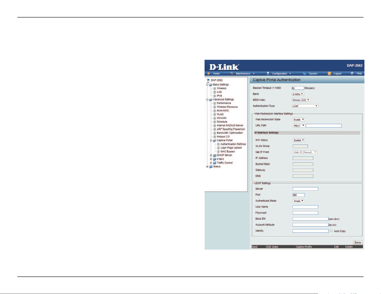
After selecting LDAP as the Authentication Type, we can congure the LDAP authentication that will be applied to each wireless client in this network.
Authentication Settings- LDAP
Session
timeout(1-1440) :
Band :
SSID Index :
Authentication Type :
Web Redirection State :
URL Path :
IPIF Status :
VLAN Group :
Get IP From :
IP Address :
Enter the session timeout value here. This value can
be from 1 to 1440 minutes. By default, this value is
60 minutes.
Select 2.4GHz or 5GHz.
Select the SSID for this Authentication.
Select the captive portal encryption type here.
Options to choose from are Web Redirection,
Username/Password, Passcode, Remote RADIUS,
LDAP and POP3. In this section we’ll discuss the LDAP
option.
Default is Disable or select Enable to enable the
website redirection feature.
Select whether to use either HTTP or HTTPS here.
After selecting either http:// or https://, enter the URL
of the website that will be used in the space provided.
Select to Enable or Disable the Captive Portal with
its IP interface feature here.
Enter the VLAN Group ID here.
Static IP (Manual) is chosen here. Choose this option
if you do not have a DHCP server in your network, or
if you wish to assign a static IP address to the DAP-
2662. When Dynamic IP (DHCP) is selected, the other
elds here will be grayed out. Please allow about 2
minutes for the DHCP client to be functional once
this selection is made.
Assign a static IP address that is within the IP address
range of your network.

Web User Interface
56
Subnet Mask :
Gateway :
DNS :
Server:
Port:
Authenticate Mode:
Username:
Password:
Base DN:
Account Attribute:
Identity:
Enter the subnet mask. All devices in the network must share the same subnet mask.
Enter the IP address of the gateway/router in your network.
Enter a DNS server IP address. This is usually the local IP address of your gateway/router.
Enter the LDAP server’s IP address or domain name here.
Enter the LDAP server’s port number here.
Select the authentication mode here. Options to choose from are Simple and TLS.
Enter the LDAP server account’s username here.
Enter the LDAP server account’s password here.
Enter the administrator’s domain name here.
Enter the LDAP account attribute string here.
This string will be used to search for clients.
Enter the identity’s full path string here. Alternatively, select the Auto Copy checkbox to automatically add the generic full
path of the web page in the identity eld.
Web User Interface
57
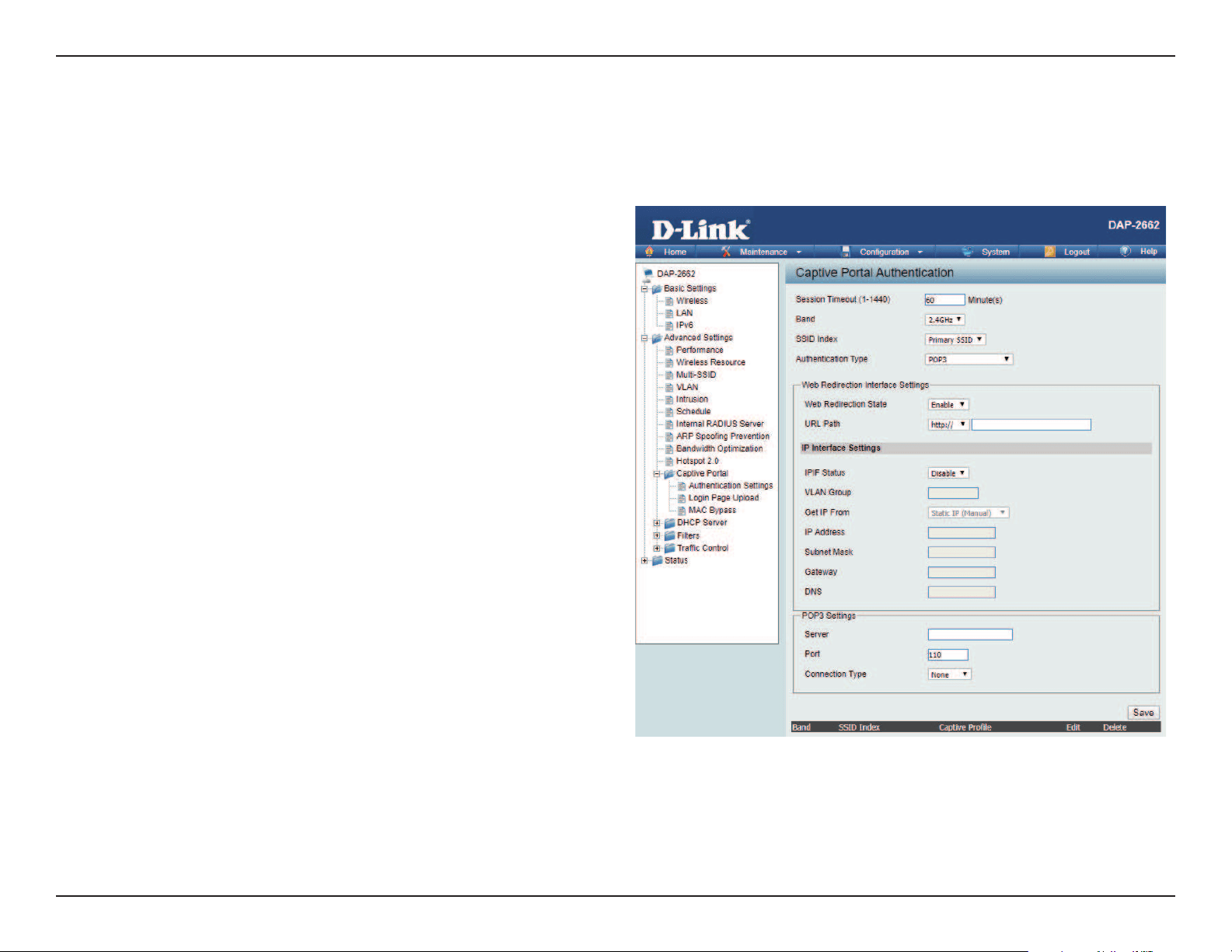
After selecting POP3 as the Authentication Type, we can congure the POP3 authentication that will be applied to each wireless client in this network.
Authentication Settings- POP3
Session
timeout(1-1440) :
Band :
SSID Index :
Authentication Type :
Web Redirection State :
URL Path :
IPIF Status :
VLAN Group :
Get IP From :
Enter the session timeout value here. This value
can be from 1 to 1440 minutes. By default, this
value is 60 minutes.
Select 2.4GHz or 5GHz.
Select the SSID for this Authentication.
Select the captive portal encryption type here.
Options to choose from are Web Redirection,
Username/Password, Passcode, Remote
RADIUS, LDAP and POP3. In this section we’ll
discuss the POP3 option.
Default is Disable or select Enable to enable the
website redirection feature.
Select whether to use either HTTP or HTTPS
here. After selecting either http:// or https://,
enter the URL of the website that will be used
in the space provided.
Select to Enable or Disable the Captive Portal
with its IP interface feature here.
Enter the VLAN Group ID here.
Static IP (Manual) is chosen here. Choose this
option if you do not have a DHCP server in
your network, or if you wish to assign a static
IP address to the DAP-2662. When Dynamic IP

Web User Interface
58
IP Address :
Subnet Mask :
Gateway :
DNS :
Server:
Port:
Connection Type:
(DHCP) is selected, the other elds here will be grayed out. Please allow about 2 minutes for the DHCP client to be functional
once this selection is made.
Assign a static IP address that is within the IP address range of your network.
Enter the subnet mask. All devices in the network must share the same subnet mask.
Enter the IP address of the gateway/router in your network.
Enter a DNS server IP address. This is usually the local IP address of your gateway/router.
Enter the POP3 server’s IP address or domain name here.
Enter the POP server’s port number here.
Select the connection type here. Options to choose from are None and SSL/TLS.
Web User Interface
59
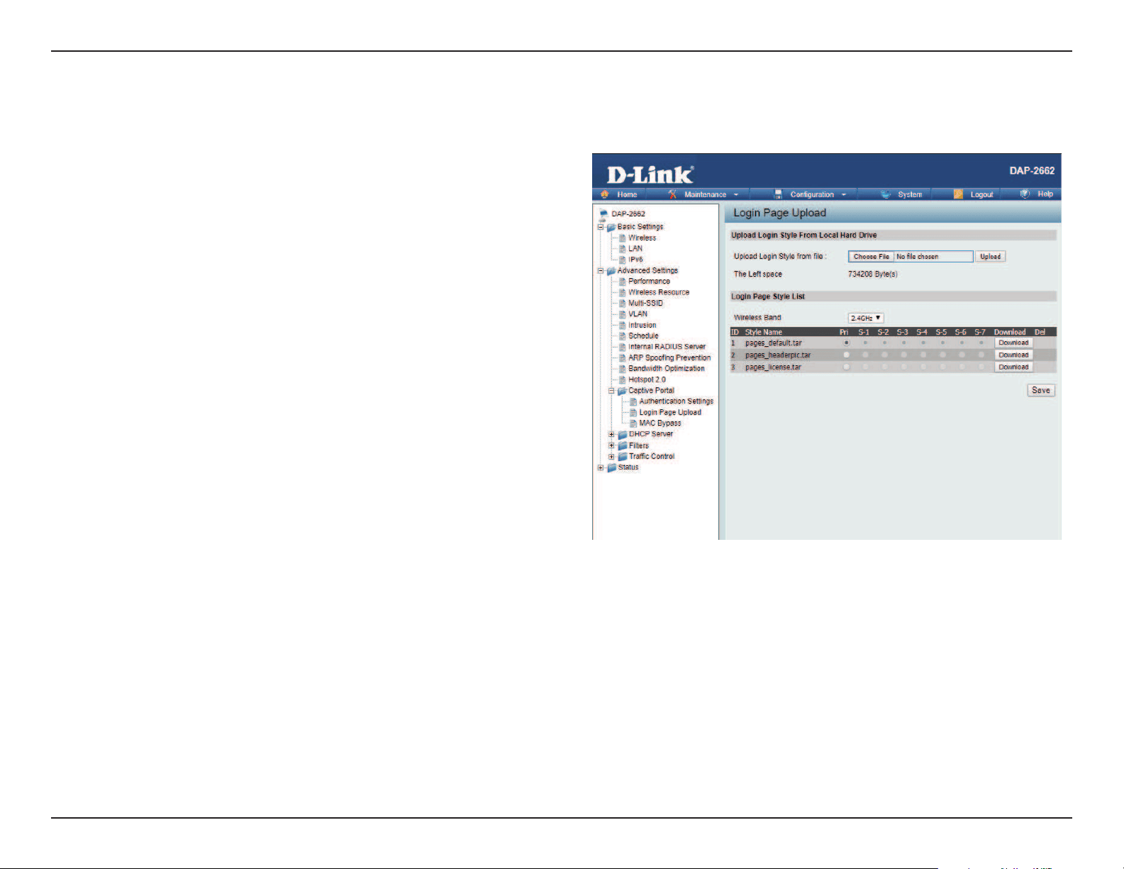
In this window, users can upload a custom login web page that will be used by the captive portal feature. Click the Browse button to navigate to
the login style, located on the managing computer and then click the Upload button to initiate the upload.
Upload Login Style
From Local Hard Drive:
Login Page Style List :
In this eld the path to the login style le that will
be uploaded, will be displayed. Alternatively, the
path can be manually entered here.
Select the wireless band and login style that will
be used in each SSID here. Click Download button
to download the template le for login page and
Click Del button to delete the template le.
Login Page Upload
Web User Interface
60
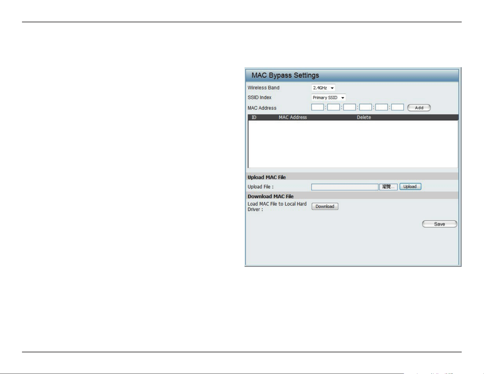
MAC Bypass
The DAP-2662 features a wireless MAC Bypass. Once a user is nished with these settings, click Save for changes to take eect.
Wireless Band:
SSID Index:
MAC Address:
MAC Address List:
Upload File:
Load MAC File to Local
Hard Driver:
Select the wireless band for MAC Bypass.
Select the SSID for MAC Bypass.
Enter each MAC address that you wish to include
in your bypass list, and click Add.
When a MAC address is entered, it appears in
this list.
Highlight a MAC address and click the Delete
icon to remove it from this list.
To upload a MAC bypass list le, click Browse and
navigate to the MAC bypass list le saved on the
computer, and then click Upload.
To download MAC bypass list le, click Download
and to save the MAC bypass list.
Web User Interface
61
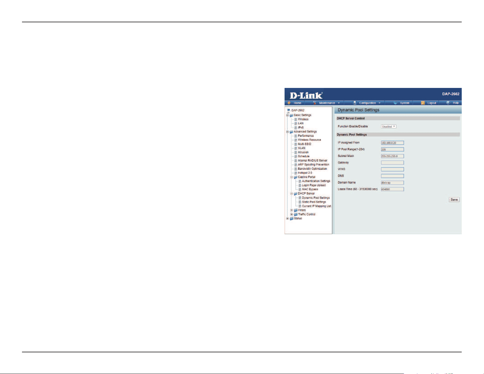
DHCP Server
The DHCP address pool denes the range of the IP address that can be assigned to stations in the network. A Dynamic Pool allows wireless stations
to receive an available IP with lease time control. If needed or required in the network, the DAP-2662 is capable of acting as a DHCP server.
Function Enable/Disable:
IP Assigned From:
The Range of Pool (1-254):
Subnet Mask:
Gateway:
WINS:
DNS:
Domain Name:
Lease Time:
Dynamic Host Configuration Protocol (DHCP) assigns
dynamic IP addresses to devices on the network. This protocol
simplies network management and allows new wireless
devices to receive IP addresses automatically without the
need to manually assign new IP addresses. Select Enable to
allow the DAP-2662 to function as a DHCP server.
Input the rst IP address available for assignment on your
network.
Enter the number of IP addresses available for assignment.
IP addresses are increments of the IP address specied in the
“IP Assigned From” eld.
Dynamic Pool Settings
All devices in the network must have the same subnet
mask to communicate. Enter the subnet mask for the
network here.
Enter the IP address of the gateway on the network.
Specify the Windows Internet Naming Service (WINS) server address for the wireless network. WINS is a system that
determines the IP address of a network computer that has a dynamically assigned IP address.
Enter the IP address of the Domain Name System (DNS) server. The DNS server translates domain names such as
www.dlink.com into IP addresses.
Enter the domain name of the network, if applicable. (An example of a domain name is: www.dlink.com.)
The lease time is the period of time before the DHCP server will assign new IP addresses.
Web User Interface
62
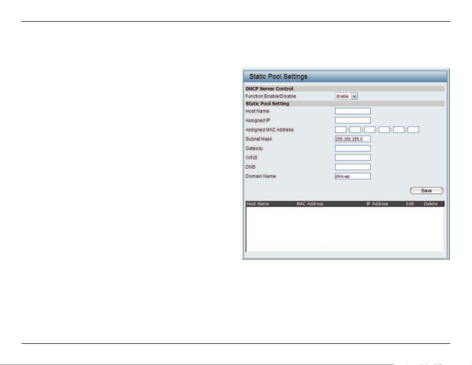
Static Pool Setting
The DHCP address pool denes the range of IP addresses that can be assigned to stations on the network. A static pool allows specic wireless
stations to receive a xed IP without time control.
Function Enable/Disable:
Assigned IP:
Assigned MAC Address:
Subnet Mask:
Gateway:
WINS:
DNS:
Domain Name:
Dynamic Host Configuration Protocol (DHCP)
assigns IP addresses to wireless devices on
the network. This protocol simplifies network
management and allows new wireless devices
to receive IP addresses automatically without
the need to manually assign IP addresses. Select
Enable to allow the DAP-2662 to function as a
DHCP server.
Use the Static Pool Settings to assign the same IP
address to a device every time you start up. The
IP addresses assigned in the Static Pool list must
NOT be in the same IP range as the Dynamic
Pool. After you have assigned a static IP address
to a device via its MAC address, click Apply; the
device will appear in the Assigned Static Pool at
the bottom of the screen. You can edit or delete
the device in this list.
Enter the MAC address of the device requesting
association here.
Dene the subnet mask of the IP address specied
in the “IP Assigned From” eld.
Specify the Gateway address for the wireless network.
Specify the Windows Internet Naming Service (WINS) server address for the wireless network. WINS is a system that
determines the IP address of a network computer with a dynamically assigned IP address, if applicable.
Enter the DNS server address for your wireless network.
Specify the domain name for the network.
Web User Interface
63
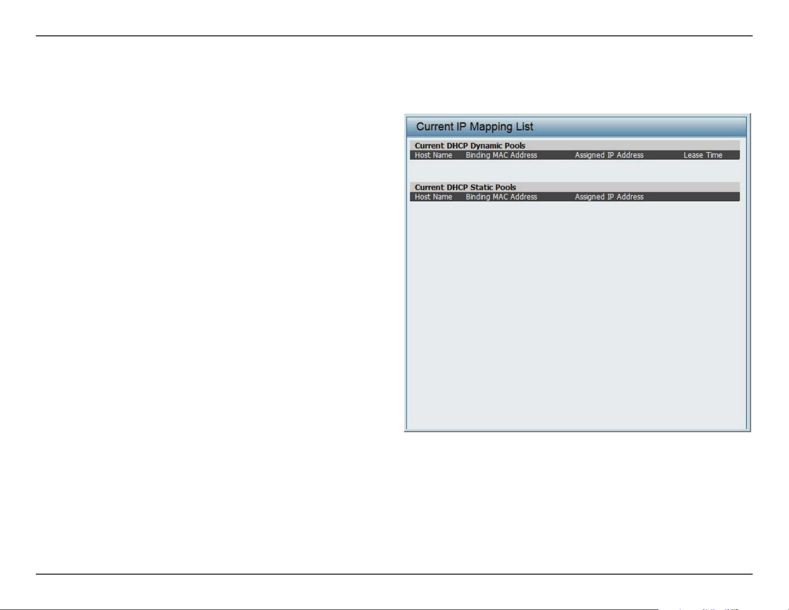
Current IP Mapping List
This window displays information about the current assigned DHCP dynamic and static IP address pools. This information is available when you
enable DHCP server on the AP and assign dynamic and static IP address pools.
Current DHCP Dynamic
Prole:
Binding MAC Address:
Assigned IP Address:
Lease Time:
Current DHCP Static Pools:
Binding MAC Address:
Assigned IP Address:
Binding MAC Address:
Assigned IP Address:
These are IP address pools the DHCP server has
assigned using the dynamic pool setting.
The MAC address of a device on the network
that is assigned an IP address from the DHCP
dynamic pool.
The current corresponding DHCP-assigned IP
address of the device.
The length of time that the dynamic IP address
will be valid.
These are the IP address pools of the DHCP
server assigned through the static pool settings.
The MAC address of a device on the network
that is within the DHCP static IP address pool.
The current corresponding DHCP-assigned
static IP address of the device.
The MAC address of a device on the network
that is assigned an IP address from the DHCP
dynamic pool.
The current corresponding DHCP-assigned
static IP address of the device.
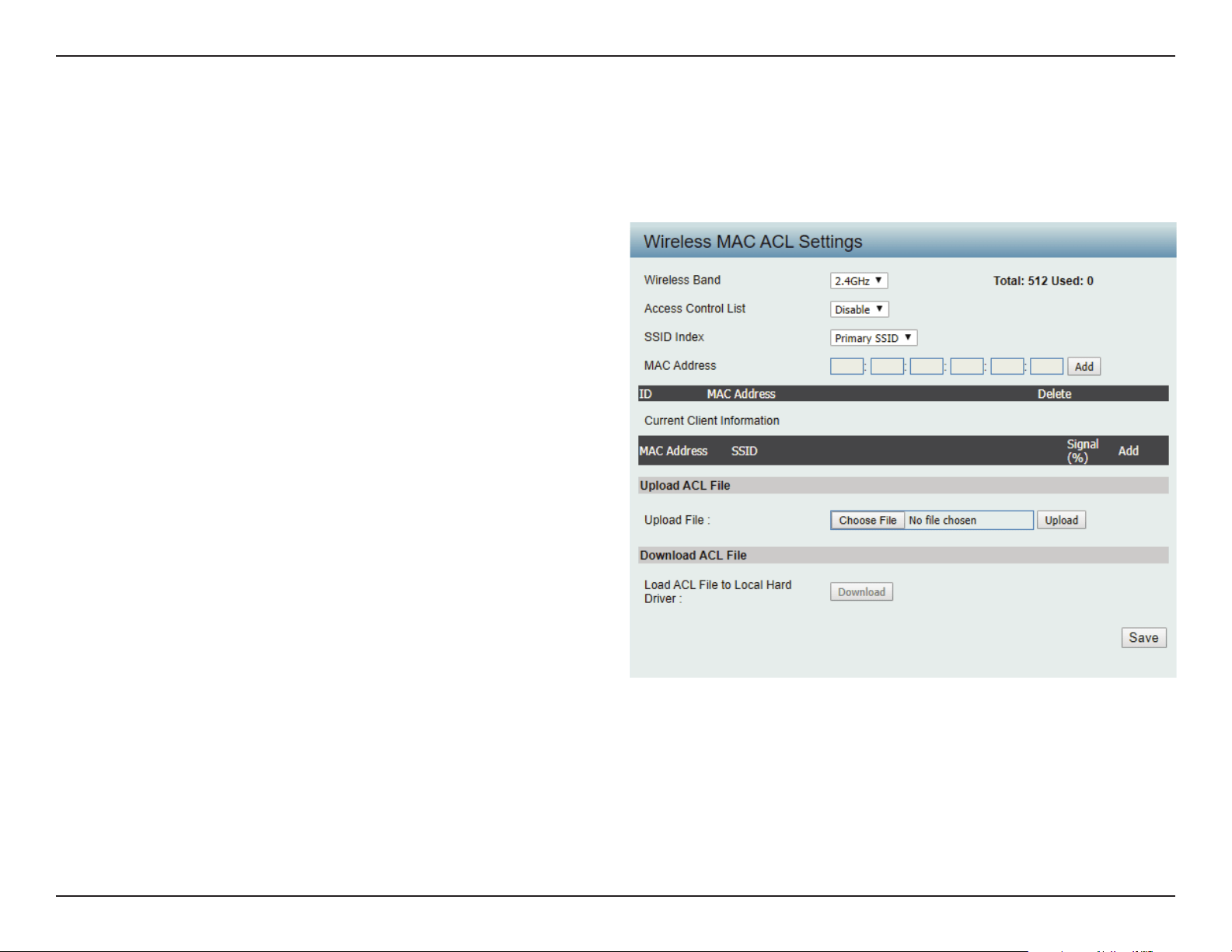
Web User Interface
64
Filters
This page allows the user to congure Wireless MAC ACL settings for access control.
Wireless Band:
Access Control List:
MAC Address:
MAC Address List:
Current Client
Information:
Upload ACL File:
Download ACL File:
Displays the current wireless band rate.
Select Disable to disable the lters function.
Select Accept to accept only those devices with MAC
addresses in the Access Control List. All other devices
not on the list will be rejected.
Select Reject to reject the devices with MAC
addresses on the Access Control List. All other devices
not on the list will be accepted.
Enter each MAC address that you wish to include in
your lter list, and click Apply.
When you enter a MAC address, it appears in this list.
Highlight a MAC address and click Delete to remove
it from this list.
This table displays information about all the current
connected stations.
Upload the user’s own ACL File here.
Download currenty ACL list to local hard drive.
Wireless MAC ACL
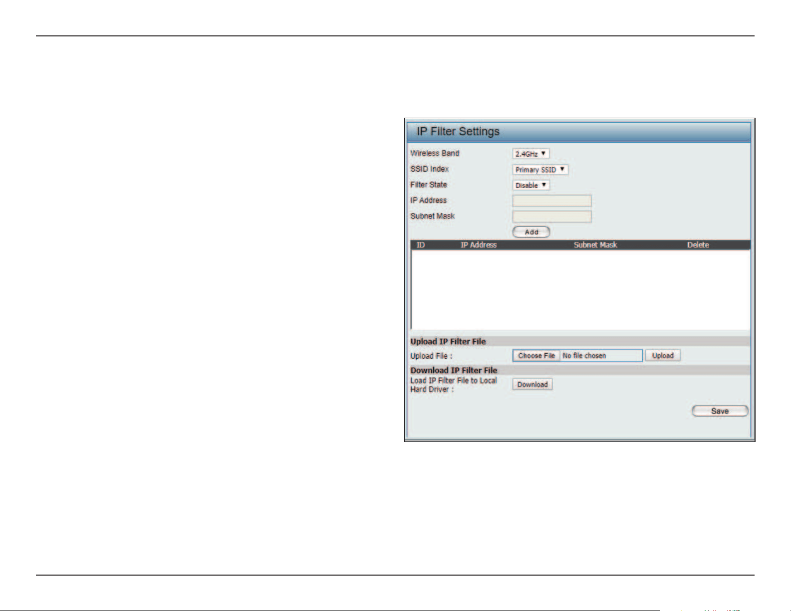
Web User Interface
65
Enter the IP address or network address that will be used in the IP lter rule. For example, an IP address like 192.168.70.66 or a network address
like 192.168.70.0. This IP address or network will be inaccessible to wireless clients in this network.
IP Filter Settings
Wireless Band: Click the drop-down menu to select the
wireless band, 2.4GHz or 5GHz.
SSID Index: Click the drop-down menu to select the SSID
for the IP lter.
Filter State: Click the drop-down menu to enable or
disable the lter state. By default this feature
is disabled.
IP Address: Enter the IP address or network address.
Subnet Mask: Enter the subnet mask of the IP address or
networks address.
IP Address List: When an IP address is entered, it appears in
the list.
Highlight a IP address and click Delete icon
to remove it from the list.
Upload IP Filter File: To upload a IP lter list le, click Choose File
and navigate to the IP lter list le saved on
the computer, and then click Upload.
Download IP Filter File: To download IP Filter list le, click Download
and to save the IP lter list.
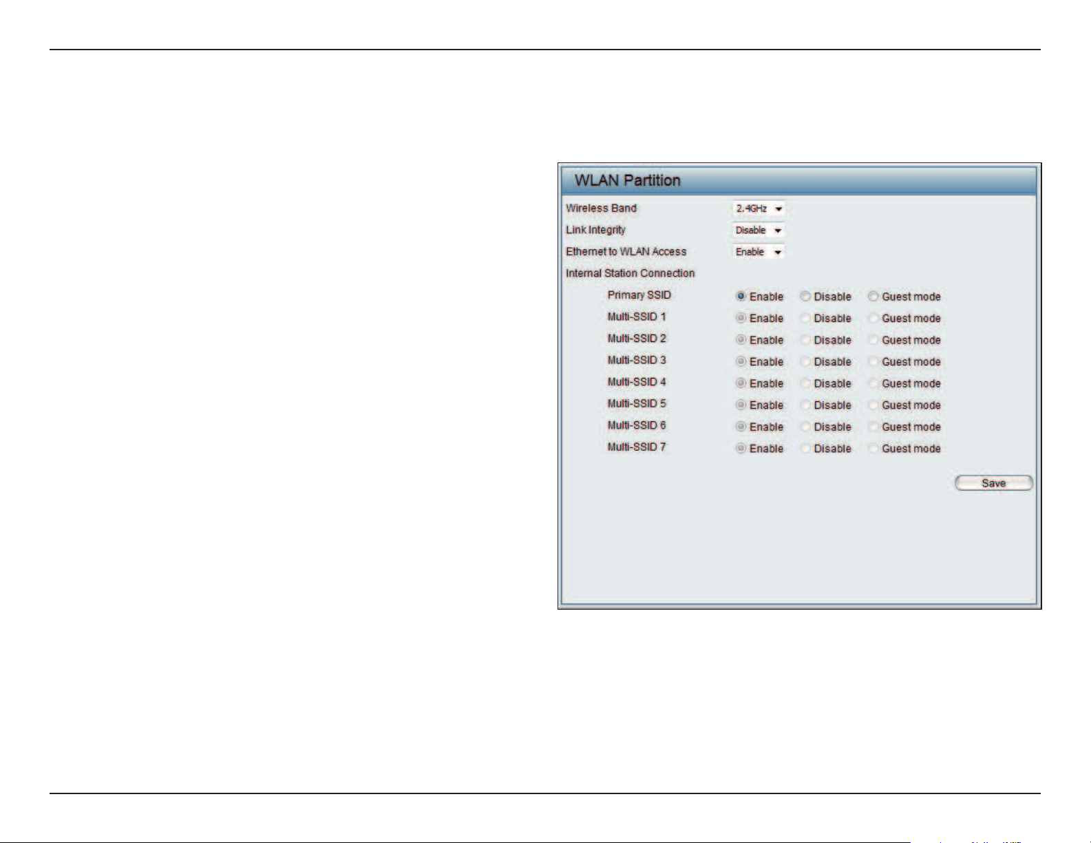
Web User Interface
66
This page allows the user to congure a WLAN Partition.
Wireless Band:
Link Integrity:
Ethernet WLAN Access:
Internal Station
Connection:
Displays the current wireless band.
Select Enable or Disable. If the Ethernet
connection between the LAN and the AP is
disconnected, enabling this feature will cause
the wireless segment associated with the AP to
be disassociated from the AP.
The default is Enable. When disabled, all data
from the Ethernet to associated wireless devices
will be blocked. Wireless devices can still send
data to the Ethernet.
The default value is Enable, which allows stations
to intercommunicate by connecting to a target
AP. When disabled, wireless stations cannot
exchange data on the same Multi-SSID. In Guest
mode, wireless stations cannot exchange data
with any station on your network.
WLAN Partition
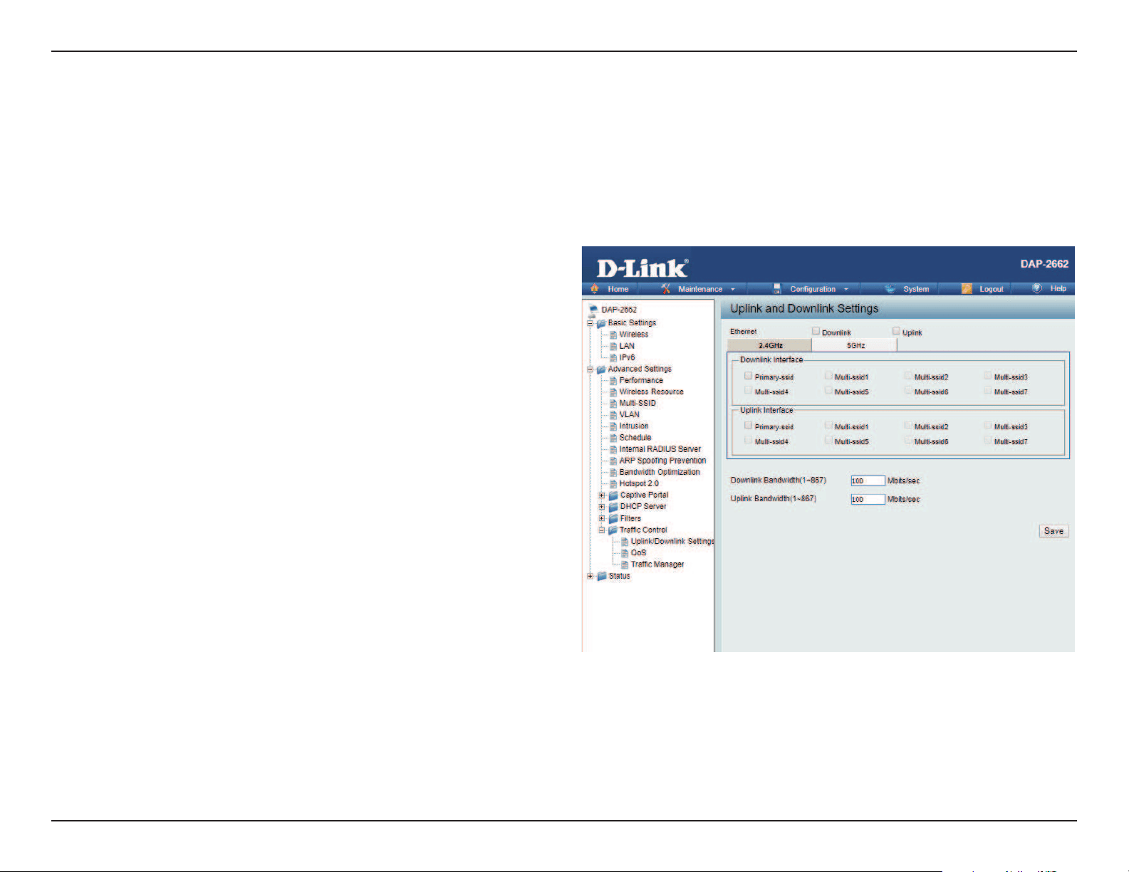
Web User Interface
67
Trac Control
The uplink/downlink setting allows users to customize the downlink and uplink interfaces including specifying downlink/uplink bandwidth rates in
Mbits per second. These values are also used in the QoS and Trac Manager windows. Once the desired uplink and downlink settings are nished,
click the Save button to have your changes take eect.
Downlink Bandwidth:
Uplink Bandwidth:
The downlink bandwidth in Mbits per second.
The uplink bandwidth in Mbits per second.
Uplink/Downlink Setting
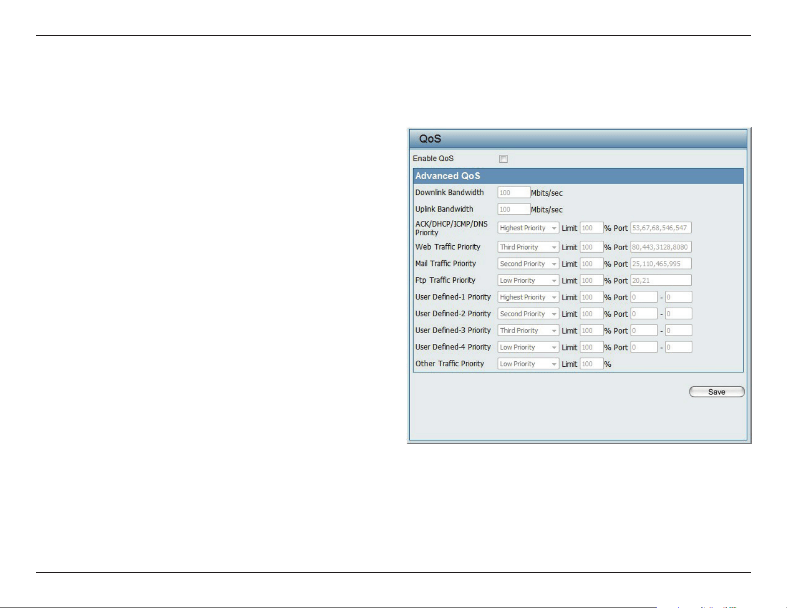
Web User Interface
68
Quality of Service (QoS) enhances the experience of using a network by prioritizing the trac of dierent applications. The DAP-2662 supports four
priority levels. Once the desired QoS settings are nished, click the Save to have your changes take eect.
Enable QoS:
Downlink Bandwidth:
Uplink Bandwidth:
Check this box to allow QoS to prioritize trac.
Use the drop-down menus to select the four
levels of priority. Click the Save button when
you are nished.
Downlink Bandwidth: The downlink bandwidth
in Mbits per second. This value is entered in the
Uplink/Downlink Setting window.
Uplink Bandwidth: The uplink bandwidth in
Mbits per second. This value is entered in the
Uplink/Downlink Setting window.
QoS
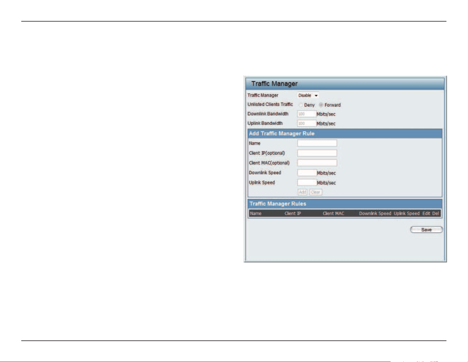
Web User Interface
69
The trac manager feature allows users to create trac management rules that specify how to deal with listed client trac and specify downlink/
uplink speed for new trac manager rules. Click the Save to have your changes take eect.
Trac Manager:
Unlisted Client Trac:
Downlink Bandwidth:
Uplink Bandwidth:
Name:
Client IP (optional):
Client MAC (optional):
Downlink Speed:
Uplink Speed:
Use the drop-down menu to Enable the
trac manager feature.
Select Deny or Forward to determine how
to deal with unlisted client trac.
The downlink bandwidth in Mbits per
second. This value is entered in the Uplink/
Downlink Setting window.
The uplink bandwidth in Mbits per second.
This value is entered in the Uplink/Downlink
Setting window.
Enter the name of the trac manager rule.
Enter the client IP address of the trac
manager rule.
Enter the client MAC address of the trac
manager rule.
Enter the downlink speed in Mbits per
second.
Enter the uplink speed in Mbits per second.
Trac Manager
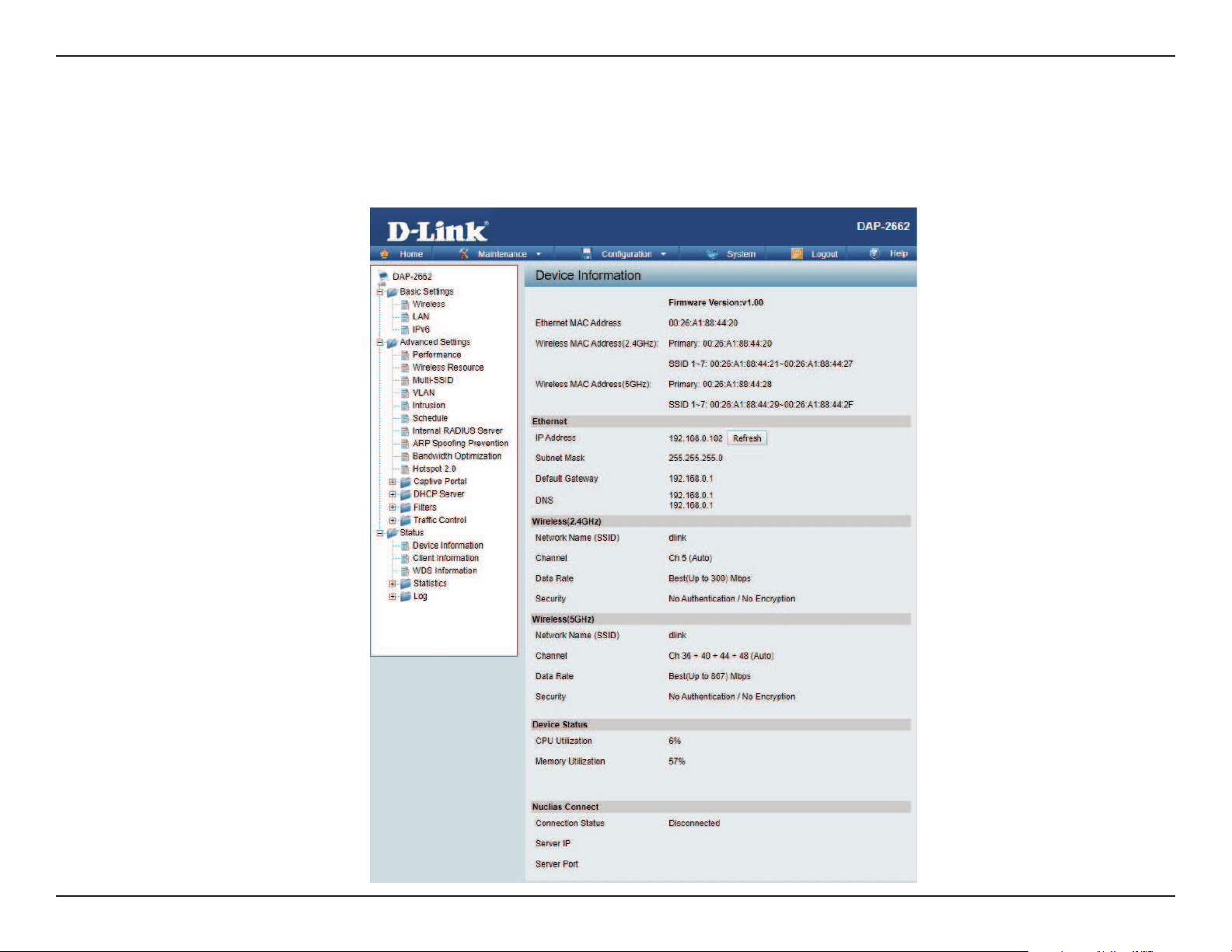
Web User Interface
70
Status
In the Status Section the user can monitor and view conguration settings of the access point. Here the user can also view statistics about client
information, WDS information and more. The following pages will explain settings found in the Status section in more detail.
Web User Interface
71
Device Information
This page displays the current information like rmware version, Ethernet and wireless parameters, as well as the information regarding CPU and
memory utilization.
Device Information: This read-only window displays the
configuration settings of the DAP-2662,
including the firmware version and the
device’s MAC address.
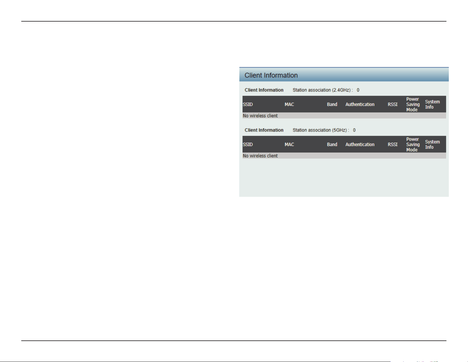
Web User Interface
72
Client Information
This page displays the associated clients SSID, MAC, band, authentication method, signal strength, RSSI, and power saving mode for the DAP-2662
network.
Client Information:
SSID:
MAC:
Band:
Authentication:
RSSI:
Power Saving Mode:
This window displays the wireless client
information for clients currently connected
to the DAP-2662.
Displays the SSID of the client.
Displays the MAC address of the client.
Displays the wireless band that the client is
connected to.
Displays the type of authentication being
used.
Displays the client’s signal strength.
Displays the status of the power saving
feature.
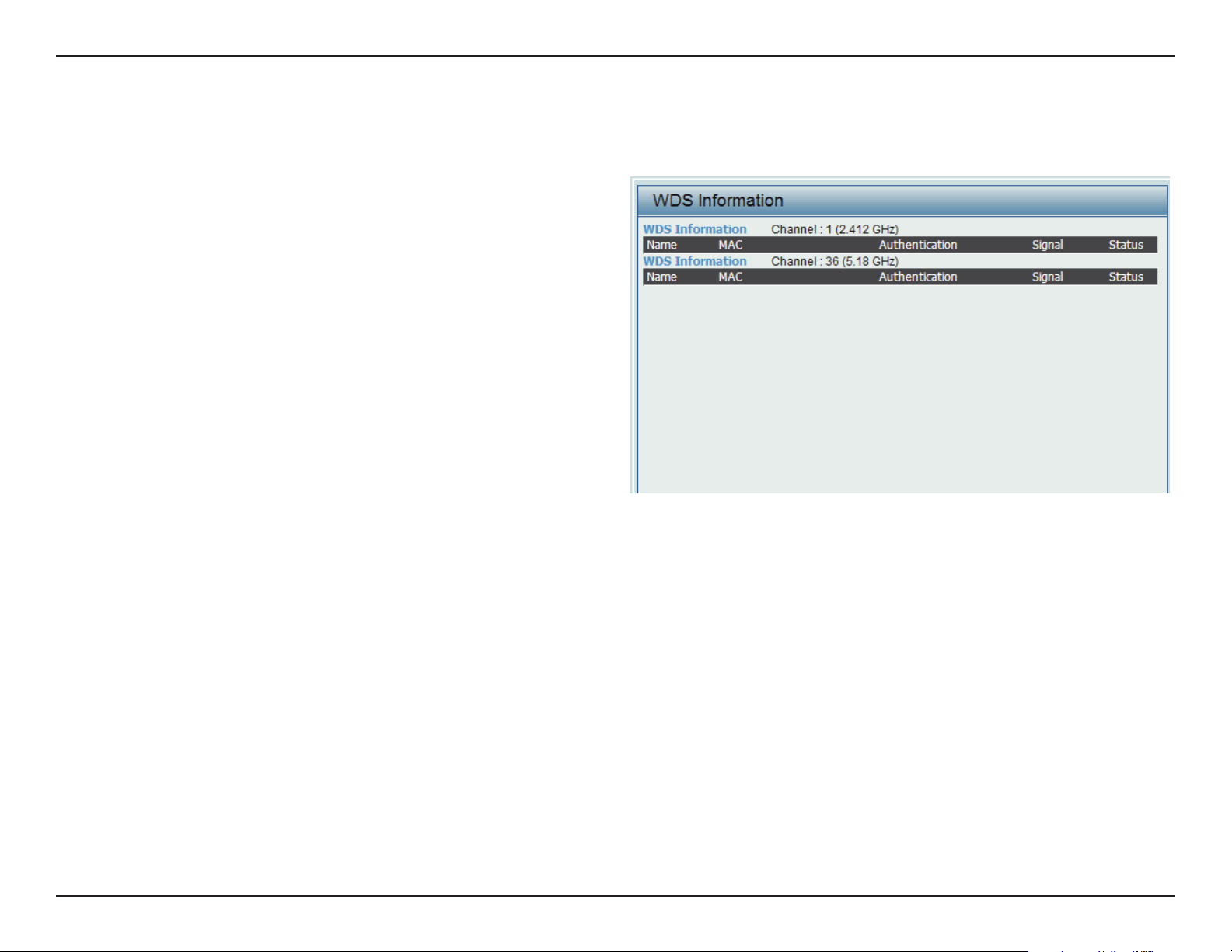
Web User Interface
73
WDS Information Page
This page displays the access points SSID, MAC, band, authentication method, signal strength, and status for the DAP-2662’s Wireless Distribution
System network.
WDS Information:
Name:
MAC:
Authentication:
Signal:
Status:
This window displays the Wireless Distribution
System information for clients currently
connected to the DAP-2662.
Displays the SSID of the client.
Displays the MAC address of the client.
Displays the type of authentication being
used.
Displays the client’s signal strength.
Displays the status of the power saving
feature.
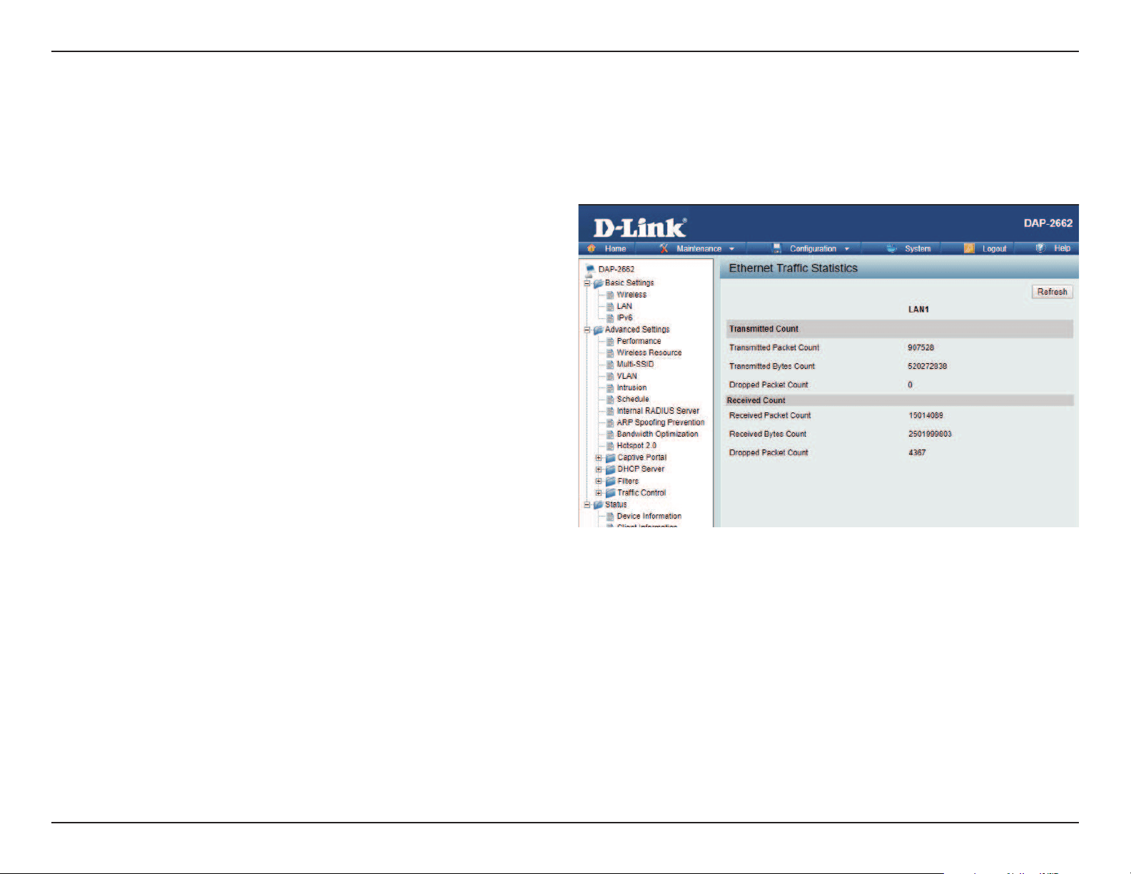
Web User Interface
74
Statistics
Displays wired interface network trac information.
Ethernet Trac Statistics: This page displays transmitted and received
count statistics for packets and bytes.
Ethernet Trac Statistics
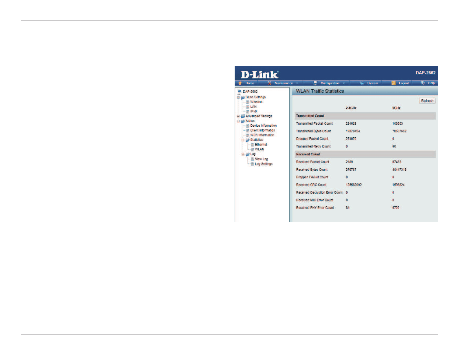
Web User Interface
75
WLAN Trac Statistics
Displays throughput, transmitted frame, received frame, and WEP frame error information for the AP network.
WLAN Trac Statistics: This page displays wireless network
statistics for data throughput,
transmitted and received frames, and
frame errors.
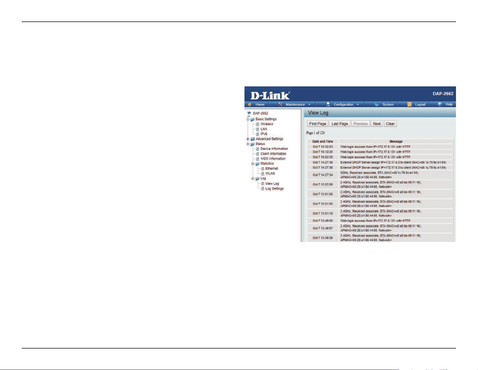
Web User Interface
76
Log
The AP’s embedded memory holds logs here. The log information includes but is not limited to the following items: cold start AP, upgrading rmware,
client associate and disassociate with AP, and web login. The web page holds up to 500 logs.
View Log: The AP’s embedded memory displays
system and network messages including
a time stamp and message type. The log
information includes but is not limited
to the following items: cold start AP,
upgrading rmware, client associate and
disassociate with AP, and web login. The
web page holds up to 500 logs.
View Log
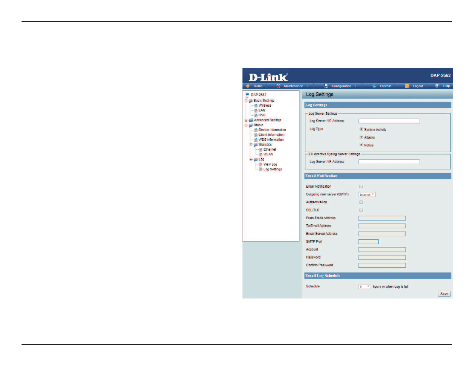
Web User Interface
77
Log Settings
Enter the log server’s IP address to send the log to that server. Check or uncheck System Activity, Wireless Activity, or Notice to specify what kind
of log type you want it to log.
Log Server / IP Address: Enter the IP address of the log server.
Log Type: Check the boxes to select the log type.
Log Server / IP Address: Enter the IP address of the EU directive Syslog
server.
Email Notication: Check the box to enable sending email
notication.
Outgoing mail server
(SMTP):
Click the drop-down menu to select the SMTP
server type, options include: Internal, Gmail,
Hotmail.
Authentication: Check the box to enable the authentication
of the email notication.
SSL/TLS: Check the box to enable the SSL/TLS function.
From Email Address: Enter the email address.
To Email Address: Enter the email address.
Email Server Address: Enter the email server address.
SMTP Port: Enter the SMTP port.
User Name: Enter the name of the new user entry.
Password: Enter the password set for the email
notication.
Conrm Password: Retype the password entry to conrm the
password.
Schedule: Click the drop-down menu to set email log
schedule.
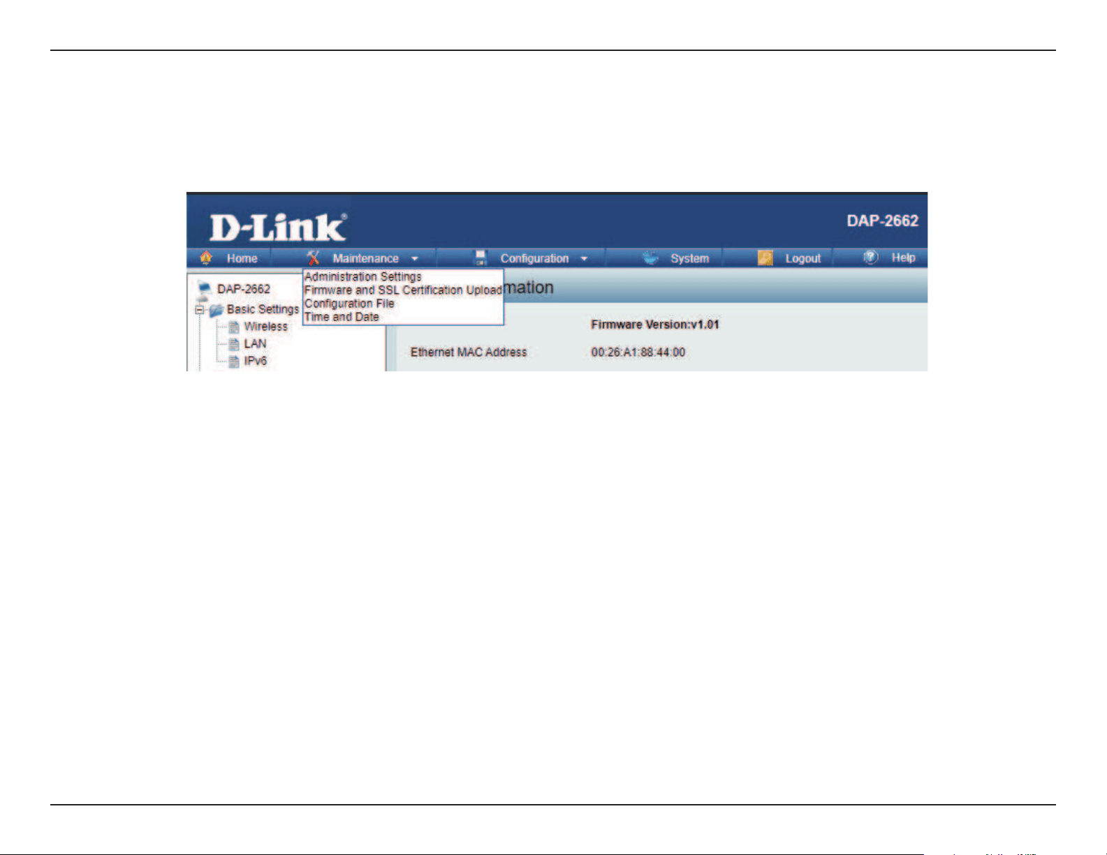
Web User Interface
78
Maintenance Section
In the Status Section the user can monitor and view conguration settings of the access point. Here the user can also view statistics about client
information, WDS information and more. The following pages will explain settings found in the maintenance section in more detail.
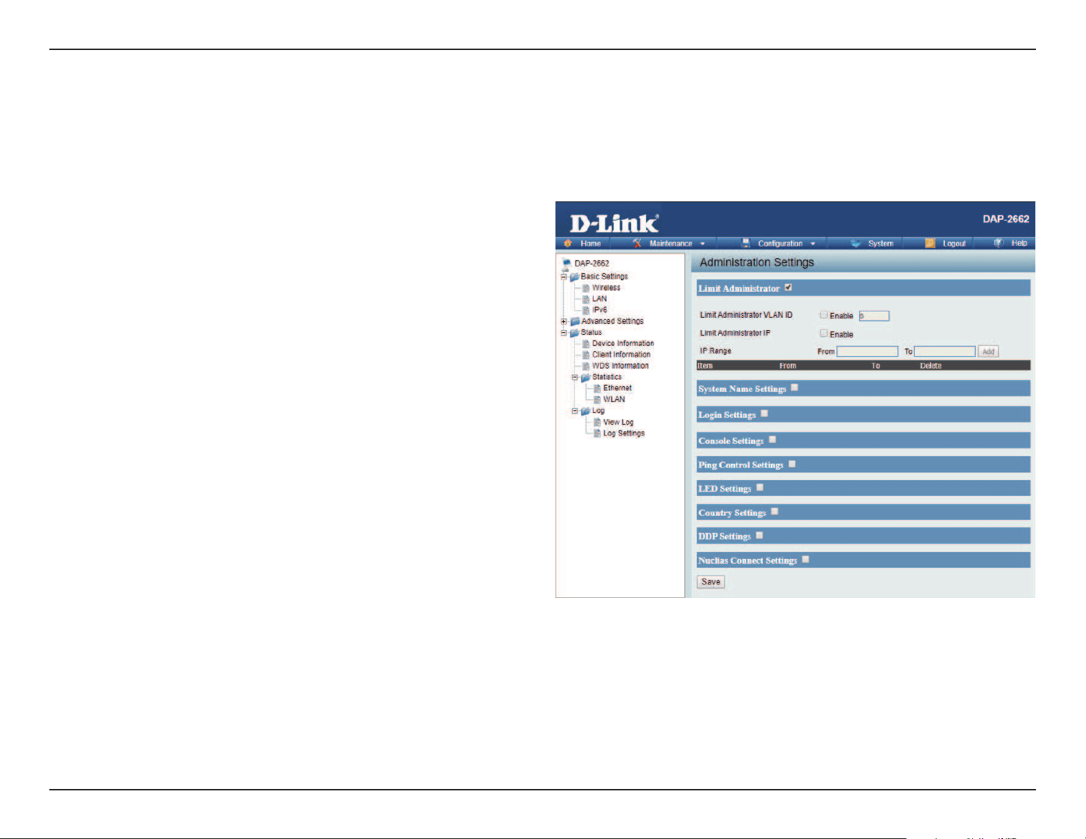
Web User Interface
79
Administration
Check one or more of the ve main categories to display the various hidden administrator parameters and settings displayed on the next ve pages.
Each of the nine main categories display various hidden administrator parameters and settings. Click Save when done.
Limit Administrator VLAN
ID:
Limit Administrator IP:
IP Range:
Check the box provided and the enter the
specic VLAN ID that the administrator will
be allowed to log in from.
Check to enable the Limit Administrator
IP address.
Enter the IP address range that the
administrator will be allowed to log in
from and then click the Add button.
Limit Administrator
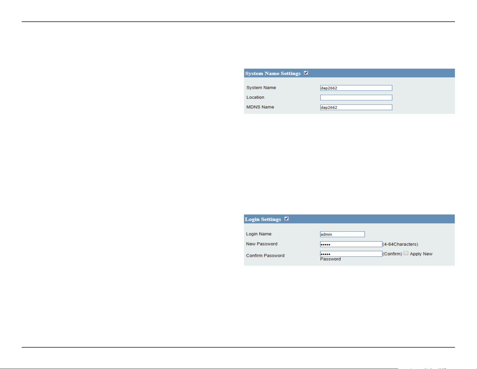
Web User Interface
80
System Name Settings
Each of the ve main categories display various hidden administrator parameters and settings.
System Name:
Location:
MDNS Name:
The name of the device. The default
name is D-Link DAP-2662.
The physical location of the device, e.g.
72nd Floor, D-Link HQ.
Enter the name of the multicast DNS. The
default name is dap2662.
Login Settings
Each of the ve main categories display various hidden administrator parameters and settings.
User Name:
Old Password:
New Password:
Conrm Password:
Enter a user name. The default is admin.
When changing your password, enter the
old password here.
When changing your password, enter
the new password here. The password is
case-sensitive. “A” is a dierent character
than “a.” The length should be between
0 and 12 characters.
Enter the new password a second time
for conrmation purposes.
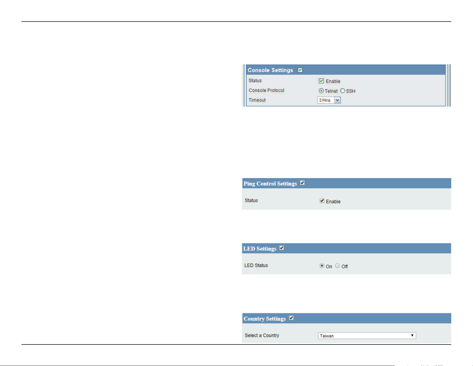
Web User Interface
81
Ping Control Settings
Choose to enable or disable ping function.
Enable: Click to disable. (By default it is enabled.)
LED Settings
Choose to enable or disable LED status.
LED Status: Choose corresponding radio button to
enable or disable LED Status.
Country Settings
Select your country.
Select a Country: Choose from the drop down list the
country your device is located.
Console Settings
Each of the ve main categories display various hidden administrator parameters and settings.
Status:
Console Protocol:
Time-out:
Status is enabled by default. Uncheck the
box to disable the console.
Select the type of protocol you would
like to use, Telnet or SSH.
Set to 1 Min, 3 Mins, 5 Mins, 10 Mins, 15
Mins or Never.
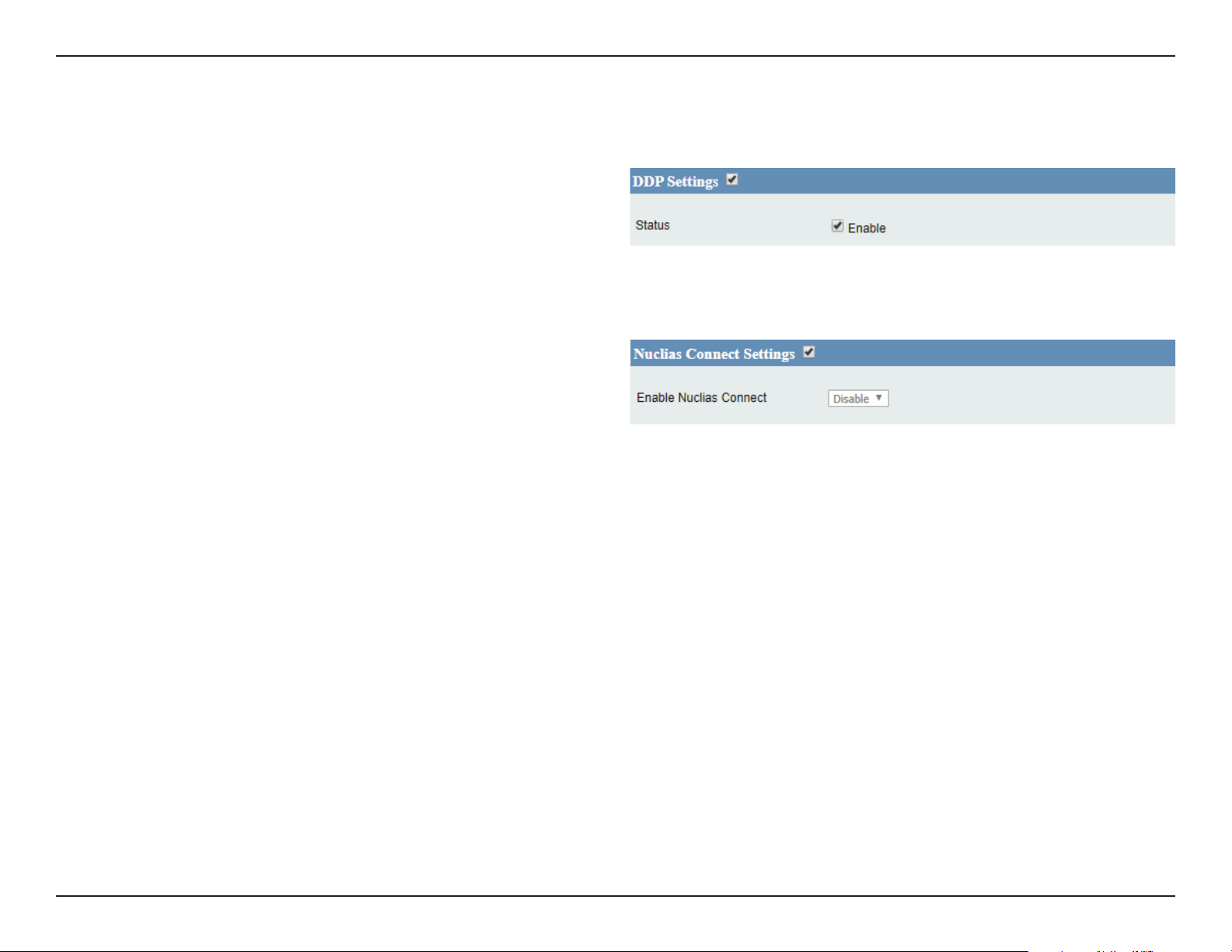
Web User Interface
82
Nuclias Connect Settings
Choose to enable or disable Nuclias Connect.
Enable Nuclias Connect: Choose from drop down list to enable or
disable Nuclias Connect.
DDP Settings
Choose to enable or disable DDP.
Status: Click to disable. (By default it is enabled.)

Web User Interface
83
Firmware and SSL Upload
This page allows the user to perform a rmware upgrade. A Firmware upgrade is a function that upgrade the running software used by the access
point. This is a useful feature that prevents future bugs and allows for new features to be added to this product. Please go to your local D-Link
website to see if there is a newer version of the rmware available.
Upload Firmware from
Local Hard Drive:
Language Pack Upgrade:
Upload SSL Certication
from Local Hard Drive:
The current rmware version is displayed
above the le location eld. After the
latest rmware is downloaded, click on
the “Choose File” button to locate the
new rmware. Once the le is selected,
click on the “Open” and “Update” button
to begin updating the rmware. Please
don’t turn the power o while upgrading.
You can upload an updated language
pack from the device here. Click on the
“Choose File” button to locate the new
language pack. Once the le is selected,
click on the “Open” and “Update” button
to being updating the language les.
After you have downloaded a SSL
certication to your local drive, click
“Choose File.” Select the certication and
click “Open” and “Upload” to complete
the upgrade. You can upload a SSL Key
in the same way.
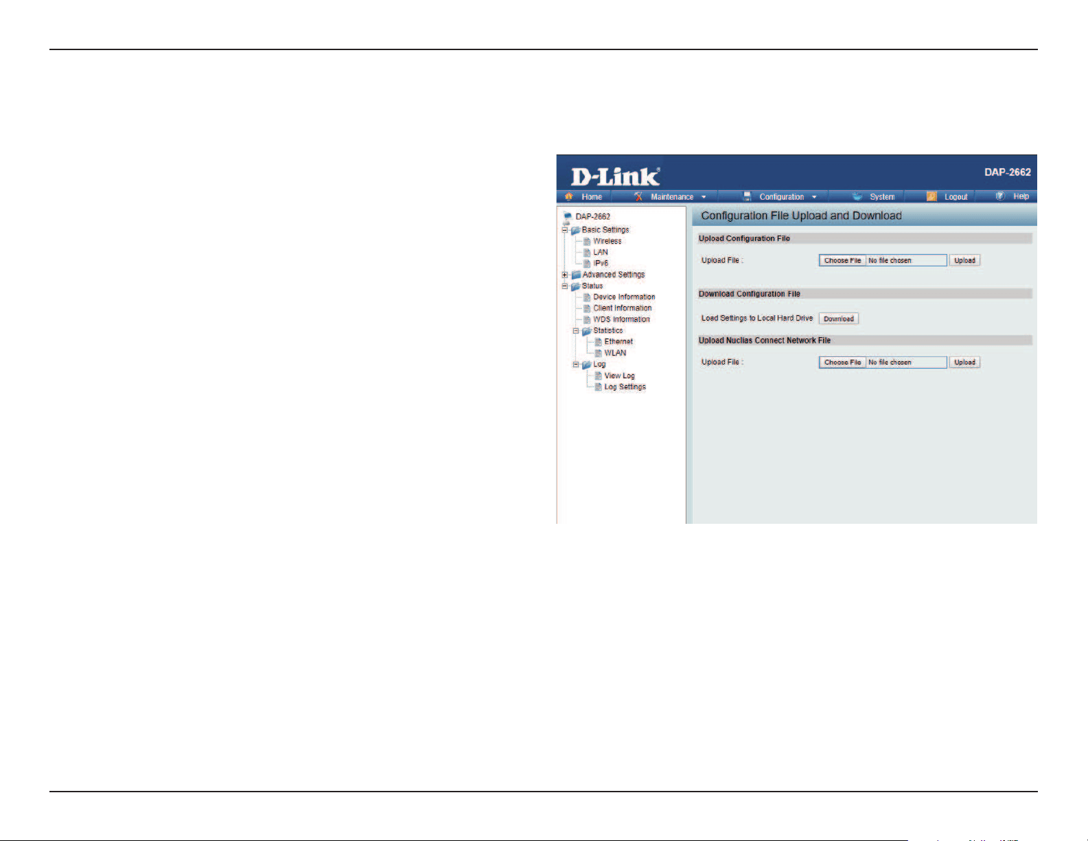
Web User Interface
84
Conguration File Upload
This page allows the user to backup and recover the current conguration of the access point in case of a unit failure.
Conguration File Upload
and Download:
Upload Conguration File:
Download Conguration
File:
Upload Nuclias Connect
Network File:
You can upload and download
conguration les of the access point.
Browse to the saved conguration
le you have in local drive and click
“Open” and “Upload” to update the
conguration.
Click “Download” to save the current
conguration le to your local disk. Note
that if you save one conguration le
with the administrator’s password now,
after resetting your DAP-2662 and then
updating to this saved conguration le,
the password will be gone.
Browse to the saved conguration le
you have in local drive and click “Open”
and “Upload” to update the Nuclias
Connect Network le.
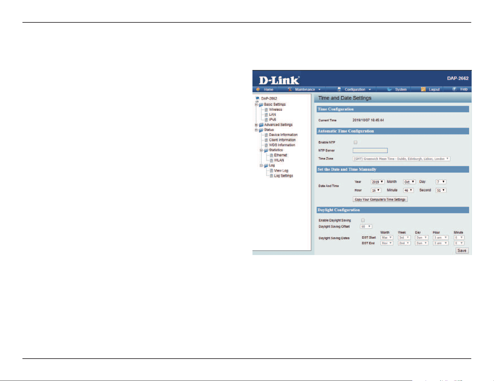
Web User Interface
85
Time and Date Settings
Enter the NTP server IP, choose the time zone, and enable or disable daylight saving time.
Current Time:
Enable NTP Server:
NTP Server:
Time Zone:
Enable Daylight
Saving:
Daylight Saving
Dates:
Set the Date and
Time Manually:
Displays the current time and date settings.
Check to enable the AP to get system time
from an NTP server from the Internet.
Enter the NTP server IP address.
Use the drop-down menu to select your
correct Time Zone.
Check the box to enable Daylight Saving
Time.
Use the drop-down menu to select the
correct Daylight Saving oset.
A user can either manually set the time
for the AP here, or click the Copy Your
Computer’s Time Settings button to copy
the time from the computer in use (Make
sure that the computer’s time is set correctly).
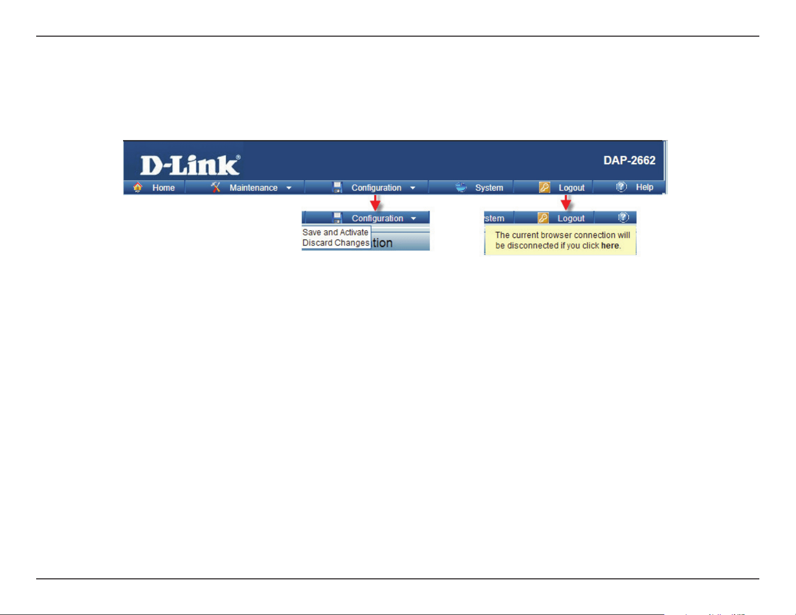
Web User Interface
86
Conguration and System
These options are the remaining option to choose from in the top menu. Conguration allows the user to save and activate or discard the congurations
done. System allows the user to restart the unit, perform a factory reset or clear the language pack settings. Logout allows the user to safely log
out from the access point’s web conguration. Help allows the user to read more about the given options to congure without the need to consult
the manual. The following pages will explain settings found in the conguration and system section in more detail.
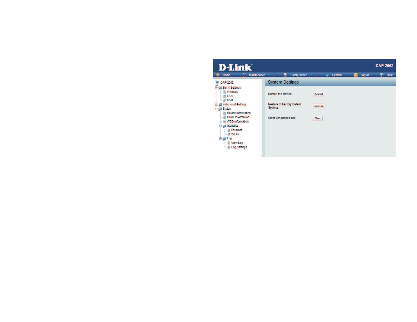
Web User Interface
87
System Settings
On this page the user can restart the unit, perform a factory reset of the access point or clear the added language pack.
Restart the Device:
Restore to Factory Default
Settings:
Clear Language Pack:
Click Restart to restart the DAP-2662.
Click Restore to restore the DAP-2662
back to factory default settings.
Click to clear the current Language pack
running.
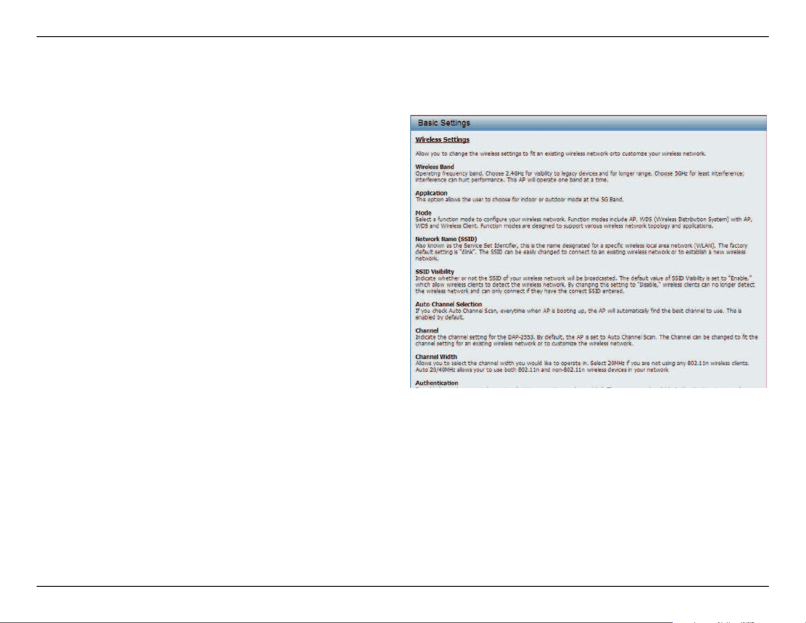
Web User Interface
88
Help
The help page is useful to view a brief description of a function available on the access point in case the manual is not present.
Help: Scroll down the Help page for topics and
explanations.

Knowledge Base
89
Knowledge Base
D-Link wireless products are based on industry standards to provide high-speed wireless connectivity that is easy to use within your home,
business or public access wireless networks. D-Link wireless products provides you with access to the data you want, whenever and wherever
you want it. Enjoy the freedom that wireless networking can bring to you.
WLAN use is not only increasing in both home and oce environments, but in public areas as well, such as airports, coee shops and universities.
Innovative ways to utilize WLAN technology are allowing people to work and communicate more eciently. Increased mobility and the absence
of cabling and other types of xed infrastructure have proven to be benecial to many users.
Wireless adapter cards used on laptop and desktop systems support the same protocols as Ethernet adapter cards, allowing wireless users to use
the same applications as those used on a wired network.
People use WLAN technology for many dierent purposes:
• Mobility - productivity increases when people can have access to data in any location within the operating range of their WLAN.
Management decisions based on real-time information can signicantly improve the eciency of a worker.
• Low implementation costs - WLANs are easy to set up, manage, change and relocate. Networks that frequently change can benet from
WLAN’s ease of implementation. WLANs can operate in locations where installation of wiring may be impractical.
• Installation and network expansion - by avoiding the complications of troublesome cables, a WLAN system can be fast and easy during
installation, especially since it can eliminate the need to pull cable through walls and ceilings. Wireless technology provides more versatility
by extending the network beyond the home or oce.
• Inexpensive solution - wireless network devices are as competitively priced as conventional Ethernet network devices. The DAP-2662 saves
money by providing users with multi-functionality congurable in four dierent modes.
• Scalability - Congurations can be easily changed and range from Peer-to-Peer networks, suitable for a small number of users to larger
Infrastructure networks to accommodate hundreds or thousands of users, depending on the number of wireless devices deployed.
Wireless Basics

Knowledge Base
90
The D-Link Access Point lets you access your network using a wireless connection from virtually anywhere within the operating range of your
wireless network. Keep in mind, however, that the number, thickness and location of walls, ceilings, or other objects that the wireless signals must
pass through, may limit the range. Typical ranges vary depending on the types of materials and background RF (radio frequency) noise in your
home or business. The key to maximizing wireless range is to follow these basic guidelines:
1. Keep the number of walls and ceilings between the access point and other network devices to a minimum. Each wall or ceiling can reduce
your adapter’s range from 3-90 feet (1-30 meters.) Position your devices so that the number of walls or ceilings is minimized.
2. Be aware of the direct line between network devices. A wall that is 1.5 feet thick (.5 meters), at a
3. 45-degree angle appears to be almost 3 feet (1 meter) thick. At a 2-degree angle it looks over 42 feet (14 meters) thick! Position devices so
that the signal will travel straight through a wall or ceiling (instead of at an angle) for better reception.
4. Building Materials make a dierence. A solid metal door or aluminum studs may have a negative eect on the range. Try to position access
points, wireless routers, and computers so that the signal passes through drywall or open doorways. Materials and objects such as glass,
steel, metal, walls with insulation, water (sh tanks), mirrors, le cabinets, brick, and concrete will degrade your wireless signal.
5. Keep your product away (at least 3-6 feet or 1-2 meters) from electrical devices or appliances that generate RF noise.
6. If you are using 2.4GHz cordless phones or X-10 (wireless products such as ceiling fans, lights, and home security systems), your wireless
connection may degrade dramatically or drop completely. Make sure your 2.4GHz phone base is as far away from your wireless devices as
possible. The base transmits a signal even if the phone in not in use.
Wireless Installation Considerations

Troubleshooting
91
Troubleshooting
When entering the IP address of the D-Link access point (192.168.0.50 for example), you are not connecting to a website on the Internet or have to
be connected to the Internet. The device has the utility built-in to a ROM chip in the device itself. Your computer must be on the same IP subnet to
connect to the web-based utility.
• Make sure you have an updated Java-enabled web browser. We recommend the following:
• Internet Explorer 7.0 or higher, Chrome, Firefox, or Safari 4 or higher
• Verify physical connectivity by checking for solid link lights on the device. If you do not get a solid link light, try using a dierent cable or connect to a
dierent port on the device if possible. If the computer is turned o, the link light may not be on.
• Disable any internet security software running on the computer. Software rewalls such as Zone Alarm, Black Ice, Sygate, Norton Personal Firewall, and
Windows® rewall may block access to the conguration pages. Check the help les included with your rewall software for more information on disabling
or conguring it.
• Congure your Internet settings:
Go to Start > Settings > Control Panel. Double-click the Internet Options Icon. From the Security tab, click the button to restore the settings to their
defaults.
Click the Connection tab and set the dial-up option to Never Dial a Connection. Click the LAN Settings button. Make sure nothing is checked. Click OK.
Go to the Advanced tab and click the button to restore these settings to their defaults. Click OK three times.
Close your web browser (if open) and open it.
• Access the web management. Open your web browser and enter the IP address of your D-Link access point in the address bar. This should open the login
page for your the web management.
• If you still cannot access the conguration, unplug the power to the access point for 10 seconds and plug back in. Wait about 30 seconds and try accessing
the conguration. If you have multiple computers, try connecting using a dierent computer.
Why can’t I access the web-based conguration utility?
This chapter provides solutions to problems that can occur during the installation and operation of the DAP-2662. Read the following
descriptions if you are having problems. (The examples below are illustrated in Windows® XP. If you have a dierent operating system, the
screenshots on your computer will look similar to the following examples.)
If you forgot your password, you must reset your access point. Unfortunately, this process will change all your settings back to the factory defaults.
To reset the access point, locate the reset button (hole) on the rear panel of the unit. With the access point powered on, use a paperclip to hold the
button down for 10 seconds. Release the button and the access point will go through its reboot process. Wait about 30 seconds to access the access
point. The default IP address is 192.168.0.50. When logging in, the username is admin and leave the password box empty.
What can I do if I forgot my password?
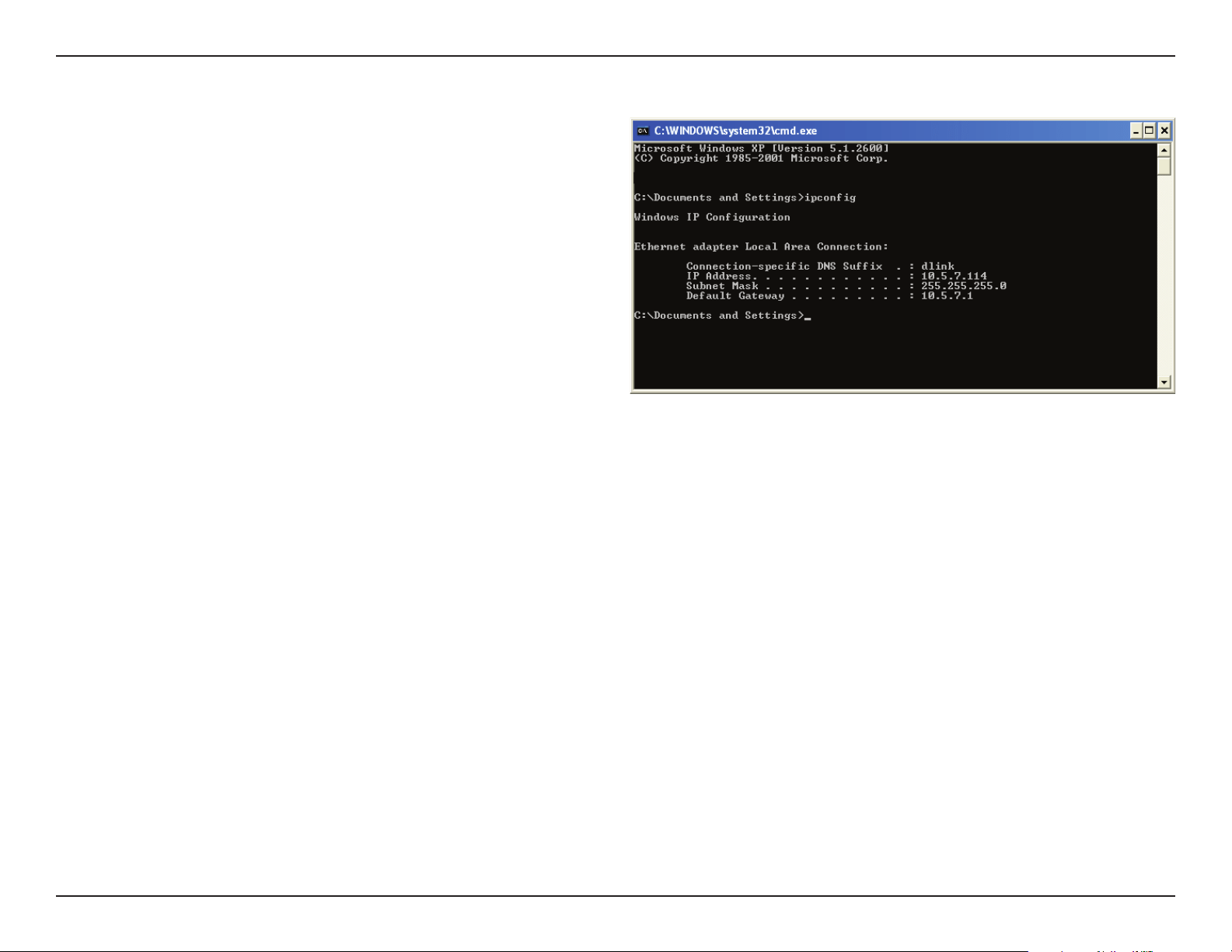
Troubleshooting
92
After you install your network adapter, by default, the TCP/IP settings
should be set to obtain an IP address from a DHCP server (i.e. wireless
router) automatically. To verify your IP address, please follow the steps
below.
Click on Start > Run. In the run box type cmd and click OK.
At the prompt, type ipcong and press Enter.
This will display the IP address, subnet mask, and the default gateway of
your adapter.
If the address is 0.0.0.0, check your adapter installation, security settings,
and the settings on your router. Some rewall software programs may
block a DHCP request on newly installed adapters.
How to check your IP address?
If you are connecting to a wireless network at a hotspot (e.g. hotel, coee shop, airport), please contact an employee or administrator to verify
their wireless network settings.
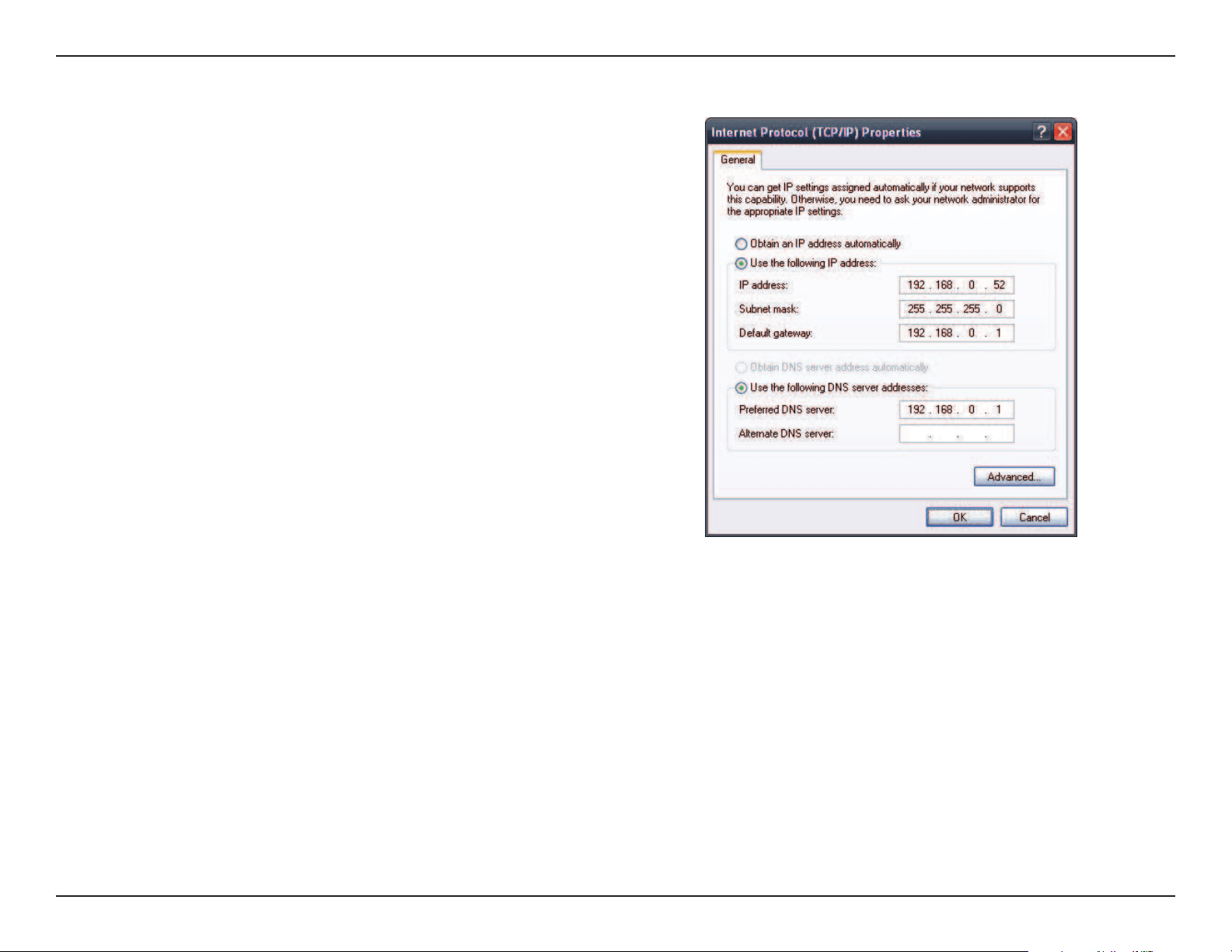
Troubleshooting
93
If you are not using a DHCP capable gateway/router, or you need to
assign a static IP address, please follow the steps below:
Step 1:
Windows® 2000: Click on Start > Settings > Control Panel > Network
Connections
Windows XP: Click on Start > Control Panel > Network Connections
Windows Vista®: Click on Start > Control Panel > Network and Internet >
Network and Sharing Center > Manage network connections
Step 2:
Right-click on the Local Area Connection which represents your network
adapter and select Properties.
Step 3:
Highlight Internet Protocol (TCP/IP) and click Properties.
Step 4:
Click Use the following IP address and enter an IP address that is on the
same subnet as your network or the LAN IP address on your router.
Example: If the router’s LAN IP address is 192.168.0.1, make your IP
address 192.168.0.X where X is a number between 2 and 99. Make sure
that the number you choose is not in use on the network. Set Default
Gateway the same as the LAN IP address of your router (192.168.0.1).
Set Primary DNS the same as the LAN IP address of your router
(192.168.0.1). The Secondary DNS is not needed or you may enter a DNS
server from your ISP.
Step 5:
Click OK twice to save your settings.
How to statically assign an IP address?

Technical Specications
94
Technical Specications
Standards
• IEEE 802.11ac
• IEEE 802.11n
• IEEE 802.11g
• IEEE 802.11a
• IEEE 802.3b
• IEEE 802.3u
• IEEE 802.3ab
• IEEE 802.3az
• IEEE 802.3af
Network Management
• Web Browser interface (HTTP, Secure HTTP (HTTPS))
• Nuclias Connect
• Command Line Interface (Telnet, Secure SSH Telnet)
Security
• WPA™ Personal/Enterprise
• WPA2™ Personal/Enterprise
• WEP™ 64-/128-bit
Wireless Frequency Range
• 2.4 to 2.4835 GHz and 5.15 to 5.85 GHz**
Operating Voltage
• 802.3af PoE or 12V/1A
Antenna Type
• 2x Detachable 3.8 dBi Omni antennas @2.4GHz
• 2x Detachable 3.8 dBi Omni antennas @5GHz
LEDs
• Power/Status
Temperature
• Operating: 0˚C to 40˚C
• Storing: -20˚C to 65˚C
Humidity
• Operating: 10%~90% (non-condensing)
• Storing: 5%~95% (non-condensing)
Certications
• FCC
• CE
• IC
• Wi-Fi
• Passpoint
Dimensions
• L = 170 mm
• W = 170 mm
• H = 28 mm
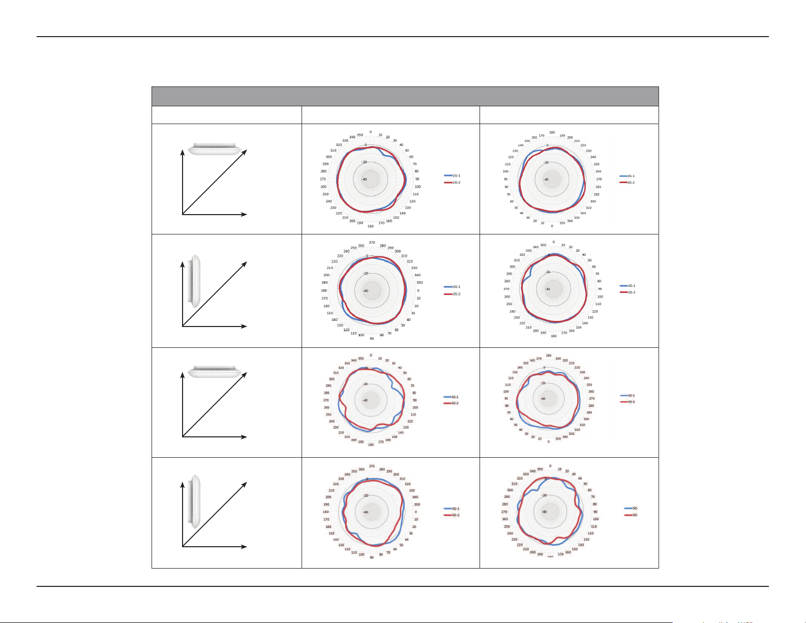
Antenna Pattern
95
Antenna Pattern
Antenna Patterns
Orientation H-Plane E-Plane
2.4 GHz Ceiling Mounted
2.4 GHz Wall Mounted
5 GHz Ceiling Mounted
5 GHz Wall Mounted
Z Y
X
Wall
(E-Plane)
Floor
(H-Plane)
Z Y
X
Wall
(E-Plane)
Floor
(H-Plane)
Z Y
X
Wall
(E-Plane)
Floor
(H-Plane)
Z Y
X
Wall
(E-Plane)
Floor
(H-Plane)