IMPORTANT MANUAL Do Not Throw Away
Poulan
OWNER'S MANUAL
MODEL NUMBER:
PP524A
SNOW THROWER
WARNING:
Read the Owner's Manual and
follow all Warnings and Safety
Instructions. Failure to do so
can result in serious injury.
Always Wear Eye Protection During Operation
187877 07.31.03 BY
Printed in U.S.A.
SAFETY RULES
A
Safe Operation Practices for SnowThrowers mL.am
IMPORTANT: This machine iscapable of amputating hands and feet and throwing objects. Failureto observe the following
safety instructions could result in serious injury or death.
Look for this symbol to point out im-
portant safety precautions. It means
CAUTION!!! BECOME ALERT!!! YOUR
SAFETY IS INVOLVED.
WARNING: Always disconnect spark
plug wire and place it where it cannot
contact plug in order to prevent acci-
dental starting when setting up, trans-
porting, adjusting or making repairs.
WARNING: This snow thrower is for
use on sidewalks, driveways and other
ground level surfaces. Caution should
be exercised while using on sloping
surfaces. Do not use snowthrower on
surfaces above ground level such as
roofs of residences, garages, porches
or other such structures or buildings.
&
WARNING: Snow throwers have ex-
posed rotating parts, which can cause
severe injury from contact, or from ma-
terial thrown from the discharge chute.
Keep the area of operation clear of all
persons, small children and pets at all
times including startup.
CAUTION: Muffler and other engine
parts become extremely hot during
operation and remain hot after engine
has stopped.To avoid severe burns on
contact, stay away from these areas.
&
WARNING: Engine exhaust, some of
its constituents, and certain vehicle
components contain or emit chemi-
cals known to the State of California
to cause cancer and birth defects or
other reproductive harm.
TRAINING
Read the operating and service instruction manual
carefully. Be thoroughly familiar with the controls and
the proper use of the equipment. Know how to stop the
unit and disengage the controls quickly.
Never allow children to operate the equipment. Never
allow adults to operate the equipment without proper
instruction.
Keep the area of operation clear of all persons, par-
ticularly small children and pets.
• Exercise caution to avoid slipping or falling especially
when operating in reverse.
PREPARATION
Remove foreign objects. Thoroughly inspect the area
where the equipment is to be used and remove all
doormats, sleds, boards, wires, rocks & landscaping.
Disengage all clutches before starting engine (mo-
tor).
Do not operate the equipment without wearing ade-
quate winter outer garments. Avoid loose, dangling
clothing, such as scarves, which can get caught in
rotating parts. Wear footwear that will improve footing
on slippery surfaces.
Handle fuel with care; it is highly flammable.
Never smoke while refueling.
Use an approved fuel container.
Never remove fuel tank cap or add fuel to a running
engine (motor) or hot engine (motor).
Fill fuel tank outdoors with extreme care. Never fill
fuel tank indoors.
Replace fuel cap securely and wipe up spilled
fuel.
STATIC
Never store fuel or snow thrower with fuel in the
tank inside of a building where fumes may reach
an open flame or spark.
Checkfuel supply before each use, allowing space
for expansion as the heat of the engine (motor)
and/or sun cause fuel to expand.
ELECTRICITY HAZARD -
Never fill containers inside a vehicle or on a truck
or trailer bed with a plastic liner. Always place
containers on the ground, away from your vehicle
before filling.
When practical, remove gas-powered equipment
from the truck or trailer and refuel it on the ground.
If this is not possible, then refuel such equipment
on a trailer with a portable container, rather than
from a gasoline dispenser nozzle.
Keep the nozzle in contact with the rim of the fuel
tankopening at alltimes, until refueling iscomplete.
Do not use a nozzle lock-open device.
If fuel is spilled on clothing, change clothing im-
mediately.
For all units with etectric starting motors use electric
starting extension cords certified CSA/UL. Use only
with a receptacle that has been installed in accordance
with local inspection authorities.
If snow thrower must be operated over gravel surface,
use extra caution and be sure skid plates are adjusted
to lowest (highest scraper clearance) position.
Never attempt to make any adjustments while the
engine (motor) is running (except when specifically
recommended by manufacturer).
Let engine (motor) and snow thrower adjust to outdoor
temperatures before starting to clear snow.
Always wear safety glasses or eye shields during op-
eration or while performing an adjustment or repair to
protect eyes from foreign objects that may be thrown
from the snow thrower.
OPERATION
Do not operate this machine if you are under the influ-
ence of alcohol or taking drugs or other medication
which can cause drowsiness or affect your ability to
operate this machine.
Do not use this machine ifyou are mentally or physically
unable to operate this machine safely.
Donotputhandsorfeetnearorunderrotatingparts.
Keepclearofthedischargeopeningandfrontauger
areaatalltimes.
Exerciseextremecautionwhenoperatingonorcross-
inggraveldrives,walksorroads.Stayalertforhidden
hazardsortraffic.
• Afterstrikingaforeignobject,stoptheengine(motor),
removewirefromthesparkplug,thoroughlyinspect
snowthrowerforanydamage,andrepairthedamage
beforerestartingandoperatingthesnowthrower.
Iftheunitshouldstarttovibrateabnormally,stopthe
engine(motor)andcheckimmediatelyforthecause.
Vibrationisgenerallyawarningoftrouble.
Stoptheengine(motor)wheneveryouleavetheoper-
atingposition,beforeuncloggingtheauger/impeller
housingordischargechuteandwhenmakingany
repairs,adjustments,orinspections.
• Whencleaning,repairing,orinspecting,makecertain
allcontrolsaredisengagedandtheauger/impellerand
allmovingpartshavestopped.Disconnectthespark
plugwireandkeepthewireawayfromthesparkplug
topreventaccidentalstarting.
• Takeallpossibleprecautionswhenleavingthesnow
throwerunattended.Disengagetheauger/impeller,stop
engine(motor),andremovekey.
Donotruntheengine(motor)indoors,exceptwhen
startingtheengine(motor)andfortransportingthe
snowthrowerinoroutofthebuilding.Open the outside
doors.
I & WARNtNG: Exhaust fumes are dan- I
gerous (containing CARBON MONOX-
IDE, an ODORLESS and DEADLY GAS).
• Do not clear snow across the face of slopes. Exercise
extreme caution when changing direction on slopes.
Do not attempt to clear steep slopes.
Never operate the snow thrower without proper guards,
plates or other safety protective devices in place.
Never operate the snow thrower near glass enclo-
sures, automobiles, window wells, drop-offs, and the
like without proper adjustment of the snow discharge
angle. Keep children and pets away.
• Do not overload the machine capacity by attempting
to clear snow at too fast a rate.
Never operate the machine at high transport speeds
on slippery surfaces. Look behind and use care when
backing up.
Never direct discharge at bystanders or allow anyone
in front of the unit.
Disengage power to the auger/impeller when snow
thrower is transported or not in use.
Use only attachments and accessories approved by
the manufacturer of the snow thrower (such as wheel
weights, counterweights, cabs, tirechains, electric start
kits, etc.).
Never operate the snow thrower without good visibility
or light. Always be sure of your footing and keep a firm
hold on the handles. Walk; never run.
Do not overreach. Keep proper footing and balance at
all times.
• This snow thrower is for use on sidewalks, driveways
and other ground level surfaces.
Do not use the snow thrower on sudaces above ground
level such as roofs of residences, garages, porches or
other such structures or buildings.
MAINTENANCE AND STORAGE
• Check shear bolts and other bolts at frequent intervals
for proper tightness to be sure the equipment is in safe
working condition.
• Never store the snowthrower with fuel in the tank inside
a building where ignition sources are present such as
hot water and space heaters, clothes dryers, and the
like. Allow the engine (motor) to cool before storing in
any enclosure.
• Always refer to operator's guide instructions for im-
portant details if the snow thrower is to be stored for
an extended period.
• Maintain or replace safety and instruction labels, as
necessary.
• Run the snow thrower, with auger engaged, a few
minutes after throwing snow to clear the machine and
prevent freeze-up of the auger/impeller.
CONGRATULATIONS on your purchase of a new snow
thrower. Ithas been designed, engineered and manufactured
to give best possible dependability and performance.
Should you experience any problem you cannot easily
remedy, please contact your nearest authorized service
center/department. We have competent, well-trained tech-
nicians and the proper tools to service or repair this unit.
Please read and retain this manual. The instructions will
enable you to assemble and maintain your snow thrower
properly. Always observe the "SAFETY RULES".
SERIAL NUMBER:
DATE OF PURCHASE:
THE MODELANDSERIAL NUMBERSWlLL BE FOUND
ON A DECALATTACHEDTOTHE REAR OFTHE SNOW
THROWER HOUSING.
YOU SHOULD RECORD BOTH SERIAL NUMBER AND
DATE OF PURCHASE AND KEEP IN A SAFE PLACE
FOR FUTURE REFERENCE.
PRODUCT SPECIFICATIONS
Gasoline Capacity 2.0 Quarts
and Type: Unleaded Regular only
Oil Type SAE 30 (above 40°F)
API-SF-SJ): SAE 5W-30 or 10W-30 (0° to +40°F
SAE 0W-30 (below 0°F)
Oil Capacity: 21 Ounces
Spark Plug: Champion RN4C (Gap: .030")
CUSTOMER RESPONSIBILITIES
• Read and observe the safety rules.
• Follow a regular schedule in maintaining, caring for
and using your snow thrower.
• Follow the instructions under"Maintenance" and "Stor-
age" sections of this owner's manual.
3
SAFETY RULES ........................................................ 2-3
PRODUCT SPECIFICATIONS ...................................... 3
CUSTOMER RESPONSIBILITIES ................................ 3
WARRANTY ................................................................ 32
ASSEMBLY / PRE-OPERATION ............................... 5-7
OPERATION ............................................................ 8-13
MAINTENANCE ..................................................... 14-15
MAINTENANCE SCHEDULE ..................................... 14
SERVICE AND ADJUSTMENTS ........................... 16-18
STORAGE ................................................................... 18
TROUBLESHOOTING ................................................ 19
REPAIR PARTS ...................................................... 20-31
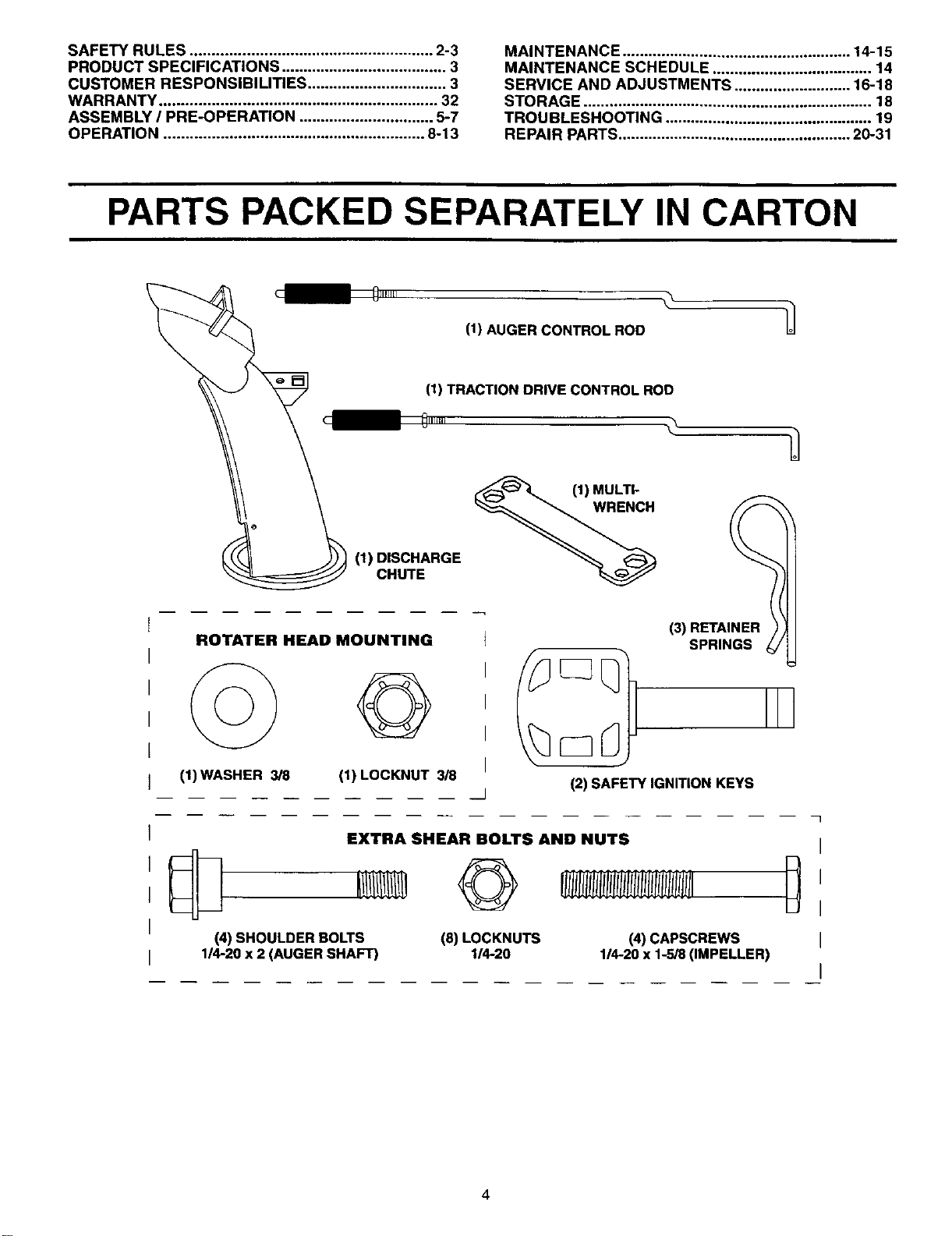
PARTS PACKED SEPARATELY IN CARTON
01111111
(1) DISCHARGE
CHUTE
ROTATER HEAD MOUNTING
©'
I
I
I
(1)WASHER 3/8 (1) LOCKNUT 3/8
/
0
(1) AUGER CONTROL ROD
(1) TRACTION DRIVE CONTROL ROD
011111, \-_
(1) MULTI-
WRENCH
(3) RETAI£
SPRINGS
(2) SAFETY IGNITION KEYS
EXTRA SHEAR BOLTS AND NUTS
(4) SHOULDER BOLTS
114-20x 2 (AUGERSHAFT)
©
(8) LOCKNUTS
114-20
(4) CAPSCREWS
1/4-20 x 1-5/8 (IMPELLER)
I
I
I
I
I
ASSEMBLY / PRE-OPERATION
Read these instructionsand this manual in its entirety before you attempt to assemble or operate your new snow thrower.
Your new snow thrower has been assembled at the factory with the exception of those parts left unassembled for shipping
purposes. All parts such as nuts, washers, bolts, etc., necessary to complete the assembly have been placed in the parts
bag. To ensure safe and proper operation of your snow thrower, all parts and hardware you assemble must be tightened
securely. Use the correct tools as necessary to ensure proper tightness.
REMOVE SNOWTHROWER FROM CARTON
t. Remove all accessible loose parts and parts boxes
from carton.
2. Cut down all four corners of carton and lay panels
flat.
3. Remove all packing materiars except plastic tie holding
speed control rod to lower handle.
4. Remove snow thrower from carton and check carton
thoroughly for additional loose parts.
HOW TO SET UP YOUR SNOW THROWER
TOOL BOX (See Fig. 8)
A toolbox is provided on your snow thrower. The toolbox
is located on top of the belt cover. Store the extra shear
bolts, nuts and multi-wrench provided in parts bag in the
toolbox.
NOTE: The multi-wrench may be used for assembly of the
chute rotator head to snowthrowerand making adjustments
to the skid plates.
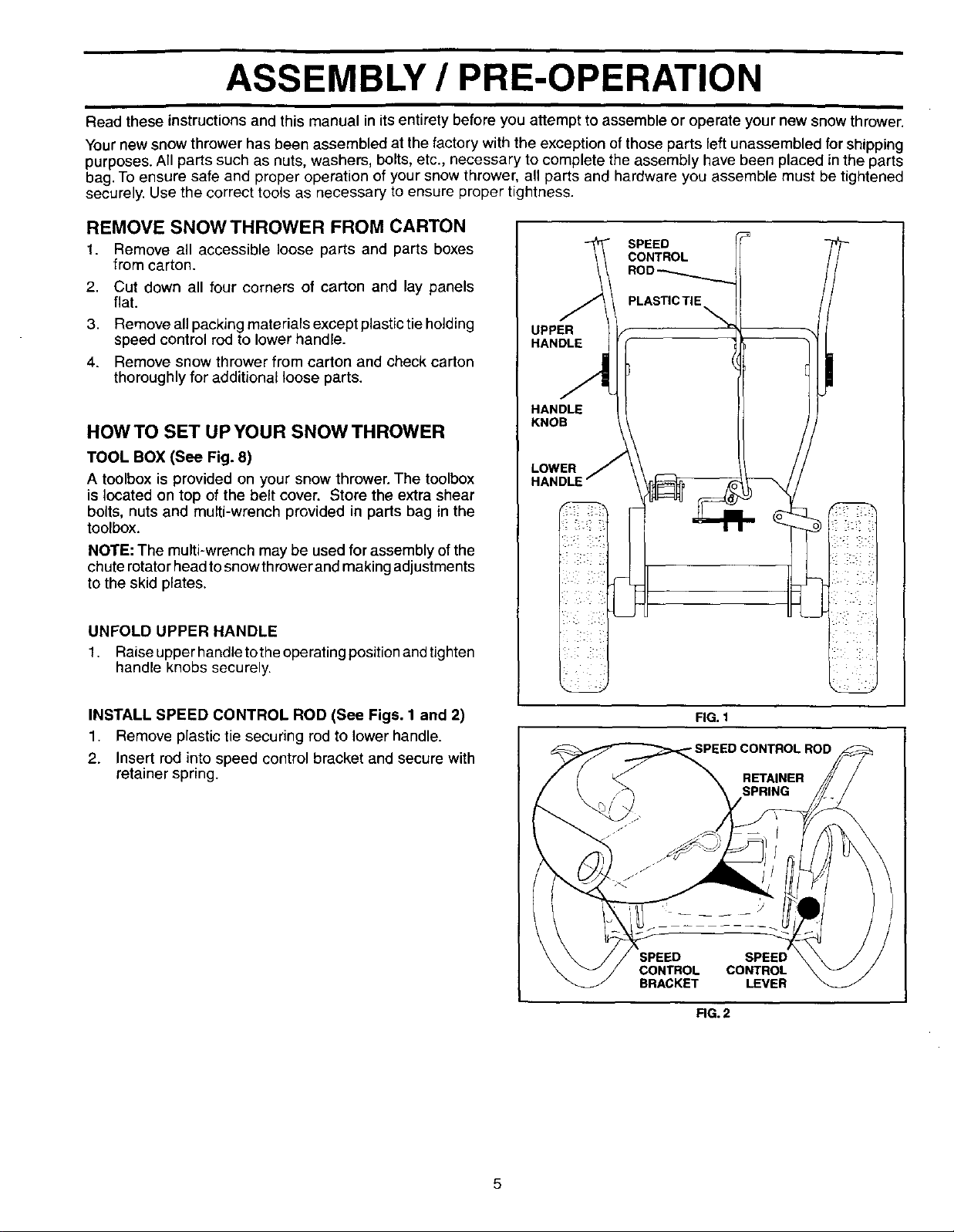
UNFOLD UPPER HANDLE
1. Raiseupperhandletotheoperatingpositionandtighten
handle knobs securely.
UPPER
HANDLE
HANDLE
KNOB
LOWER
SPEED
CONTROL
I
1
INSTALL SPEED CONTROL ROD (See Figs. 1 and 2)
1. Remove plastic tie securing rod to lower handle.
2. Insert rod into speed control bracket and secure with
retainer spring.
FIG. 1
-SPEED CONTROL ROD
RETAINER
SPRING
SPEED
CONTROL CONTROL
BRACKET LEVER
FIG.2
ASSEMBLY / PRE-OPERATION
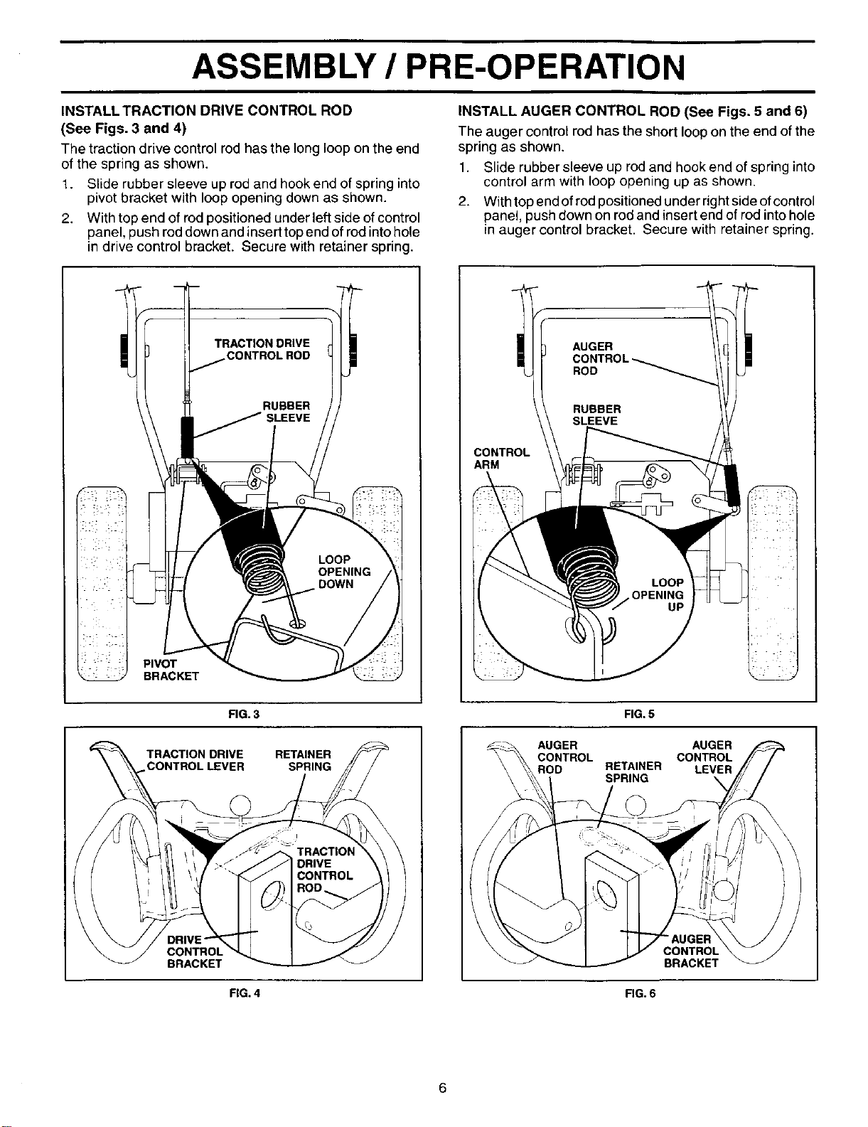
INSTALL TRACTION DRIVE CONTROL ROD
(See Figs. 3 and 4)
The traction drive control rod has the long loop on the end
of the spring as shown.
1. Slide rubber sleeve up rod and hook end of spring into
pivot bracket with loop opening down as shown.
2. With top end of rod positioned under left side of control
panel, push rod down and insert top end of rod into hole
in drive control bracket. Secure with retainer spring.
INSTALL AUGER CONTROL ROD (See Figs. 5 and 6)
The auger control rod has the short loop on the end of the
spring as shown.
1. Slide rubber sleeve up rod and hook end of spring into
control arm with loop opening up as shown.
2. With top end of rod positioned under right side ofcontrol
panel, push down on rod and insert end of rod into hole
in auger control bracket. Secure with retainer spring.
PIVOT
BRACKET
TRACTION DRIVE iCONTROL ROD
RUBBER
SLEEVE
CONTROL
ARM
AUGER
FIG. 3
TRACTION DRIVE
CONTROL LEVER
CONTROL
BRACKET
FIG. 4
RETAINER
SPRING
FIG. 5
AUGER AUGER
CONTROL CONTROL
ROD RETAINER LEVER
SPRING
CONTROL
BRACKET
FIG. 6
ASSEMBLY / PRE-OPERATION
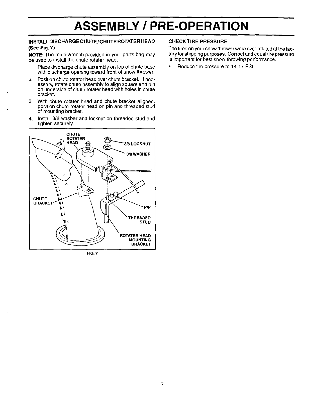
CHECK TIRE PRESSUREINSTALL DISCHARGE CHUTE/CHUTE ROTATER HEAD
(See Fig. 7)
NOTE: The multi-wrench provided in your parts bag may
be used to install the chute rotater head.
1,
2.
Place discharge chute assembly on top of chute base
with discharge opening toward front of snow thrower.
Position chute rotater head over chute bracket. If nec-
essary, rotate chute assembly to align square and pin
on underside of chute rotater head with holes in chute
bracket.
3. With chute rotater head and chute bracket aligned,
position chute rotater head on pin and threaded stud
of mounting bracket.
4. Install 3/8 washer and Iocknut on threaded stud and
tighten securely.
CHUTE
ROTATER
3/8WASHER
The tires on you rsnow thrower were overinflated at the fac-
tory for shipping purposes. Correct and equal tire pressure
is important for best snow throwing performance.
• Reduce tire pressure to 14-17 PSI.
PIN
HREADED
STUD
ROTATER HEAD
MOUNTING
BRACKET
FIG. 7
7
OPERATION
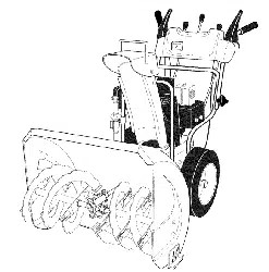
KNOW YOUR SNOW THROWER
READ THIS OWNER'S MANUAL AND ALL SAFETY RULES BEFORE OPERATING YOUR SNOWTHROWER. Compare
the illustrationswith your snow thrower to familiarize yourself with the location of various controlsand adjustments. Save
this manual for future reference.
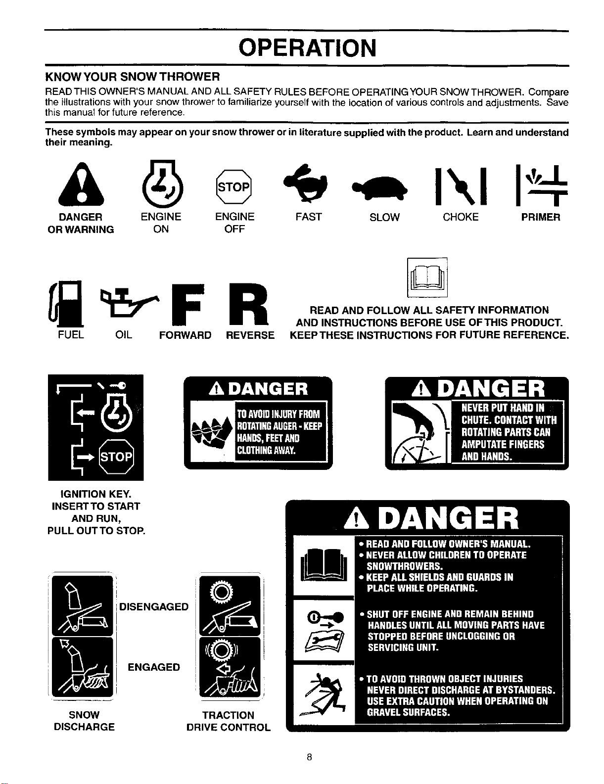
These symbols may appear on your snow thrower or in literature supplied with the product. Learn and understand
their meaning.
ENGINE FAST
OFF
I",1I
DANGER ENGINE SLOW CHOKE PRIMER
OR WARNING ON
FUEL OIL FORWARD REVERSE
READ AND FOLLOW ALL SAFETY INFORMATION
AND INSTRUCTIONS BEFORE USE OFTHIS PRODUCT.
KEEP THESE INSTRUCTIONS FOR FUTURE REFERENCE.
IGNITION KEY.
INSERT TO START
AND RUN,
PULL OUTTO STOP.
SNOW
DISCHARGE
DISENGAGED
ENGAGED
TRACTION
DRIVECONTROL
8
OPERATION
ENGINE OIL CAP AUGER DISCHARGE CHUTE CONTROL LEVER
,-WITH DIPSTICK CONTROL
LEVER
\ DRIVE SPEED
- GASOLINE _ CONTROL LEVER
FILLER
\
CAP
CHUTE
DEFLECTOR
SAFETY
IGNITION
CHOKE
CON-
SPARK
pLUG
TRACTION
DRIVE
CONTROL
LEVER
THROTTLE
/ENGINE
CONTROL
RECOIL
STARTER
HANDLE
PRIMER
NOTE: ITEMS ABOVE
ARE SHOWN IN
THEIR TYPICAL
LOCATION ON THE
ENGINE, ACTUAL
LOCATION MAY VARY
WITH THE ENGINE
ON YOUR UNIT.
FUEL SHUT-OFF VALVE
OIL DRAIN
PLUG
CHUTE
IANDLE
KNOB
MUFFLER
TOOLBOX
SKID PLATE
FIG. 8
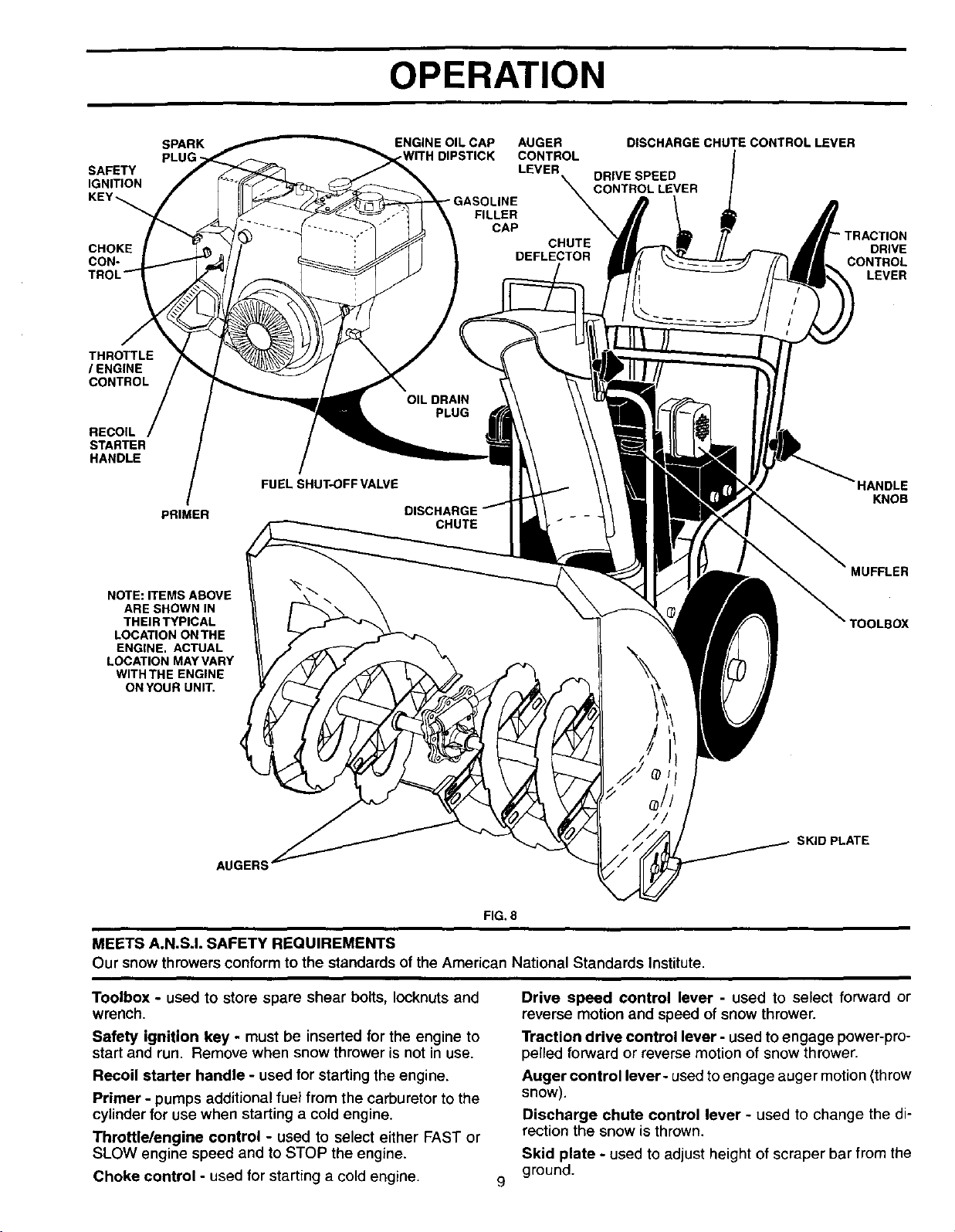
MEETS A.N.SJ. SAFETY REQUIREMENTS
Our snow throwers conform to the standards of the American National Standards Institute.
Toolbox - used to store spare shear bolts, Iocknuts and
wrench.
Safety ignition key - must be inserted for the engine to
start and run. Remove when snow thrower is not in use.
Recoil starter handle - used for starting the engine.
Primer - pumps additional fuel from the carburetor to the
cylinderfor use when starting a cold engine.
Throttle/engine control - used to select either FAST or
SLOW engine speed and to STOP the engine,
Choke control - used for starting a cold engine.
9
Drive speed control lever - used to select forward or
reverse motion and speed of snow thrower.
Traction drive control lever - used to engage power-pro-
pelled forward or reverse motion of snow thrower.
Auger control lever- used to engage auger motion (throw
snow).
Discharge chute control lever - used to change the di-
rection the snow is thrown.
Skid plate - used to adjust height of scraper bar from the
ground.
OPERATION
The operation of any snow thrower can result
in foreign objects thrown intothe eyes, which
can result in seve reeye damage. Always wear
safety glasses or eye shields while operating
your snow thrower or performing any adjust-
ments or repairs. We recommend standard safety glasses
or a wide vision safety mask worn over spectacles.
HOW TO USE YOUR SNOW THROWER
Know how to operate all controls before adding fuel or
attempting to start the engine.
STOPPING
TRACTION DRIVE
• Release traction d rive control lever to stop the forward
or reverse movement of the snow thrower.
AUGER
• Release the auger control lever to stop throwing snow.
ENGINE
1. Move throttle control to "STOP" position.
2. Remove (do not turn) safety ignition key to prevent
unauthorized use.
NOTE: Never use choke to stop engine.
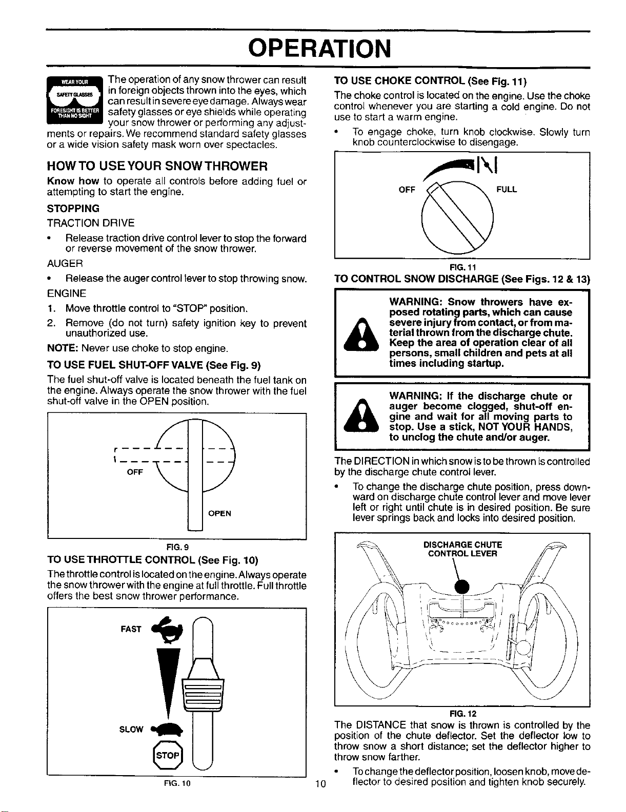
TO USE FUEL SHUT-OFF VALVE (See Fig. 9)
The fuel shut-off valve is located beneath the fuel tank on
the engine. Always operate the snow thrower with the fuel
shut-off valve in the OPEN position.
r -- _ _
OFF
DPEN
TO USE CHOKE CONTROL (See Fig. 11)
The choke control is located on the engine. Use the choke
control whenever you are starting a cold engine. Do not
use to start a warm engine.
• To engage choke, turn knob clockwise. Slowly turn
knob counterclockwise to disengage.
I, !1\1
FIG. 11
TO CONTROL SNOW DISCHARGE (See Figs. 12 & 1::
WARNING: Snow throwers have ex-
posed rotating parts, which can cause
severe injury from contact, or from ma-
terial thrown from the discharge chute.
Keep the area of operation clear of all
persons, small children and pets at all
times including startup.
WARNING: If the discharge chute or
auger become clogged, shut-off en-
gine and wait for all moving parts to
stop. Use a stick, NOT YOUR HANDS,
to unclog the chute and/or auger.
The DIRECTION inwhich snow isto be thrown is controlled
by the discharge chute control lever.
• To change the discharge chute position, press down-
ward on discharge chute control lever and move lever
left or right until chute is in desired position. Be sure
lever springs back and locks into desired position.
FIG.9
TO USE THRO'rrLE CONTROL (See Fig. 10)
The throttle controlis locatedonthe engine.Always operate
the snow thrower withthe engine at full throttle.Full throttle
offers the best snow thrower performance.
SLOW
Q
FIG. 10
DISCHARGE CHUTE
CONTROLLEVER
10
FIG.12
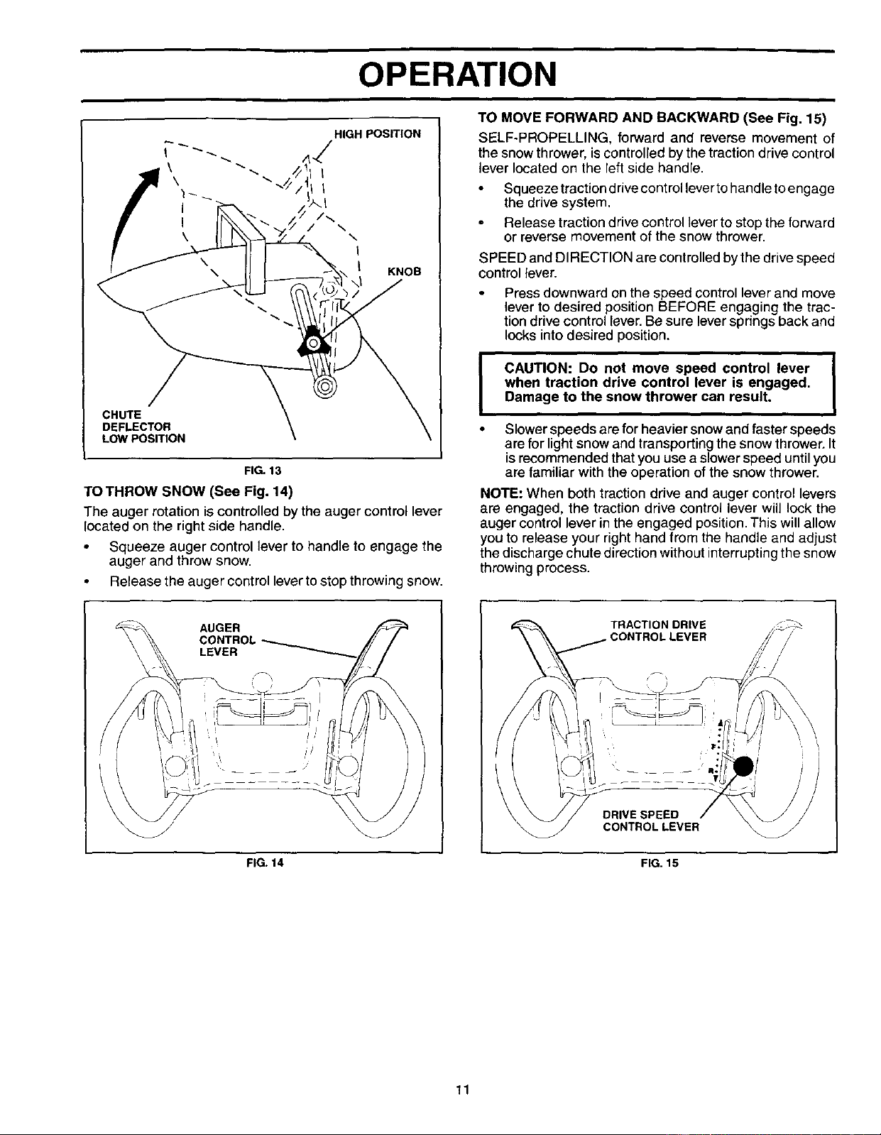
The DISTANCE that snow is thrown is controlled by the
position of the chute deflector. Set the deflector low to
throw snow a short distance; set the deflector higher to
throw snow farther.
Tochange the deflector position, loosen knob, move de-
flector to desired position and tighten knob securely.
OPERATION
\
\
I
I
\
HIGH POSITION
Z
I
I
\
\
I
KNOB
CHUTE
DEFLECTOR
LOW POSEION
FIG.13
TO THROW SNOW (See Fig. 14)
The auger rotation is controlled by the auger control lever
located on the right side handle.
• Squeeze auger control lever to handle to engage the
auger and throw snow.
Release the auger controllever tostop throwing snow.
TO MOVE FORWARD AND BACKWARD (See Fig. 15)
SELF-PROPELLING, forward and reverse movement of
the snowthrower, iscontrolledby thetraction drive control
lever located on the left side handle.
Squeeze traction drive controllever to handle toengage
the drive system.
Release traction drive control lever to stop the forward
or reverse movement of the snow thrower.
SPEED and DIRECTION are controlled by the drive speed
control lever.
Press downward on the speed control lever and move
lever to desired position BEFORE engaging the trac-
tion drive control lever. Be sure lever springs back and
locks into desired position.
!
CAUTION: Do not move speed control lever |
when traction drive control lever is engaged.
I
Damage to the snow thrower can result.
• Slower speeds are for heavier snowand faster speeds
are for lightsnow and transporting the snow thrower. It
isrecommended thatyou use a slower speed untilyou
are familiar with the operation of the snow thrower.
NOTE: When both traction drive and auger control levers
are engaged, the traction drive control lever will lock the
auger control lever in the engaged position. This will allow
you to release your right hand from the handle and adjust
thedischarge chute direction without interruptingthe snow
throwing process.
AUGER
FIG. 14
TRACTION DRIVE _7:\
CONTROLLEVER
DRIVE SPEED
CONTROL LEVER
FIG. 15
11
OPERATION
BEFORE STARTING THE ENGINE
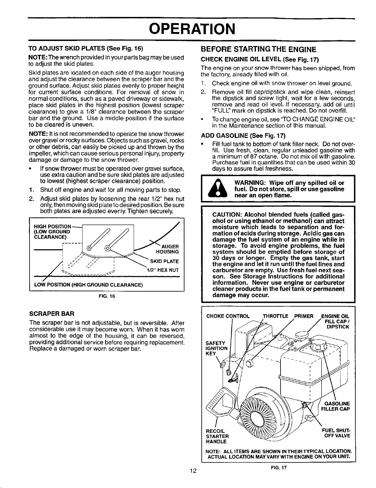
TO ADJUST SKID PLATES (See Fig. 16)
NOTE: The wrench provided inyourparts bag may be used
to adjust the skid plates.
Skid plates are located on each side of the auger housing
and adjust the clearance between the scraper bar and the
ground surface. Adjust skid plates evenly to proper height
for current surface conditions. For removal of snow in
normal conditions, such as a paved driveway or sidewalk,
place skid plates in the highest position (lowest scraper
clearance) to give a 1/8" clearance between the scraper
bar and the ground. Use a middle position if the surface
to be cleared is uneven.
NOTE: Itisnot recommended to operate the snow thrower
over gravel or rocky surfaces. Objects such as gravel, rocks
or other debris, can easily be picked up and thrown by the
impeller, which can cause serious personal injury, property
damage or damage to the snow thrower.
• If snow thrower must be operated over gravel surface,
use extra caution and be sure skid plates are adjusted
to lowest (highest scraper clearance) position.
1. Shut off engine and wait for all moving parts to stop.
2. Adjust skid plates by loosening the rear 1/2" hex nut
only, then moving skid plate to desired position. Be sure
both plates are adjusted evenly. Tighten securely.
HIGH POSITION
(LOW GROUND /
CLEARANC!) ____
I /
I // / I
/
LOW POSITION (HIGH GROUND CLEARANCE)
HOUSING
1/2" HEX NUT
FIG. 16
CHECK ENGINE OIL LEVEL (See Fig. 17)
The engine on your snow thrower has been shipped, from
the factory, already filled with oil.
1. Check engine oil with snow thrower on level ground.
2. Remove oil fill cap/dipstick and wipe clean, reinsert
the dipstick and screw tight, wait for a few seconds,
remove and read oil level. If necessary, add oil until
"FULl" mark on dipstick is reached. Do not overfill.
Tochange engine oil, see "TO CHANGE ENGINE OIU'
in the Maintenance section of this manual.
ADD GASOLINE (See Fig. 17)
• Fill fuel tank to bottom of tank filler neck. Do not over-
fill. Use fresh, clean, regular unleaded gasoline with
a minimum of 87 octane. Do not mix oil with gasoline.
Purchase fuel in quantitiesthat can be used within30
days to assure fuel freshness.
WARNING: Wipe off any spilled oil or
fuel. Do not store, spill or use gasoline
near an open flame.
CAUTION: Alcohol blended fuels (called gas-
ohol or using ethanol or methanol) can attract
moisture which leads to separation and for-
mation of acids during storage. Acidic gas can
damage the fuel system of an engine while in
storage. To avoid engine problems, the fuel
system should be emptied before storage of
30 days or longer. Empty the gas tank, start
the engine and let it run until the fuel lines and
carburetor are empty. Use fresh fuel next sea-
son. See Storage Instructions for additional
information. Never use engine or carburetor
cleaner products in the fuel tank or permanent
damage may occur.
SCRAPER BAR
The scraper bar is not adjustable, but is reversible. After
considerable use it may become worn. When it has worn
almost to the edge of the housing, it can be reversed,
providing additional service before requiring replacement.
Replace a damaged or worn scraper bar.
CHOKE CONTROL THRO'I-rLE PRIMER ENGINE OIL
FILL CAP /
DIPSTICK
SAFETY
IGNITION
KEY
GASOLINE
FILLER CAP
RECOIL FUEL SHUT-
STARTER OFF VALVE
HANDLE
NOTE: ALL ITEMS ARE SHOWN IN THEIR TYPICAL LOCATION.
ACTUAL LOCATION MAY VARY WITH ENGINE ON YOUR UNIT.
FIG.17
12
OPERATION
SNOW THROWING TIPS
TO START ENGINE
Be sure fuel shut-off valve is in the OPEN position.
Your snow thrower engine is equipped with a recoil
starter.
COLD START
1. Insert safety ignition key into the ignition slot until it
clicks. DO NOT turn the key. Keep the extra safety
ignition key in a safe place.
2. Place throttle control in FAST position.
3. Rotate choke control to FULL position.
4. Push the primer four (4) times if the temperature is
below 15°F, or two (2) times iftemperature is between
15° and 50°F. If temperature is above 50°F, priming is
not necessary.
NOTE: Over priming may cause flooding, preventing the
engine from starting. If you do flood the engine, wait a few
minutes before attempting to start and DO NOT push the
primer.
5. Pull recoil starter handle quickly. Do not allow starter
rope to snap back.
6. When the engine starts, release the recoil starter
handle and slowly move the choke control to the OFF
position.
Allow the engine to warm up for a few minutes. Engine will
not develop full power until ithas reached normal operating
temperature.
WARM START
Follow the steps above, keeping the choke in the OFF
position. DO NOT push the primer.
BEFORE STOPPING
Run the engine for a few minutes to help dry off any mois-
ture on the engine.
To avoid possible freeze-up of the starter, proceed as fol-
lows:
!. While the engine is running, pull the recoilstarter handle
with rapid, full arm strokes three or four times.
NOTE: The unusual sound made while pulling the recoil
starter handle will net harm the engine or starter.
IF RECOIL STARTER HAS FROZEN
If the recoil starter has frozen and will not turn the engine,
proceed as follows:
1. Grasp the recoil starter handle and slowly pull as much
rope out of the starter as possible.
2. Release the recoil starter handle and let it snap back
against the starter.
If the engine still fails to start, repeat the above steps.
• Always operate the snow thrower with the engine at
full throttle. Full throttle offers the best performance.
Go slower in deep, freezing or heavy wet snow. Use the
drive speed control, NOT the throttle, to adjust speed.
It is easier and more efficient to remove snow imme-
diately after itfalls.
• The best time to remove snow is the early morning. At
this time the snow is usually dry and has not been ex-
posed to the direct sun and warming temperatures.
Slightly overlap each successive path to ensure all
snow will be removed.
Throw snow downwind whenever possible.
Adjust the skid plates to proper height for current snow
conditions. See "TO ADJUST SKID PLATES" in this
section of this manual.
• For extremely heavy snow, reduce the width of snow
removal by overlapping previous path and moving
slowly.
• Keep engine clean and clear of snow during use. This
will help air flow and extend engine life.
• After snow-throwing iscompleted, allow engine to run for
a few minutes to melt snow and ice off the engine.
Clean the entire snow thrower thoroughly after each
use and wipe dry so it is ready for next use.
WARNING: Do not operate snow
thrower ifweather conditions impair vis-
ibility. Throwing snow during a heavy,
windy snowstorm can blind you and be
hazardous to the safe operation of the
snow thrower.
13
MAINTENANCE
MAINTENANCE SCHEDULE .e,
FILL IN DATES ./_.__
AS YOU COMPLETE
REGULARSERV,CE
Check for Loose Fasteners l/
I _) Clean / Inspect Snow Thrower
EW Check / Replace V-Belts
R Lubrication Chart
Check Engine Oil Level
Change Engine Oil
Inspect Muffler
Check / Replace Spark Plug
Empty Fuel Tank
v'
l/
v'
i/
v'
l/
i/
i/
i/
v'
i/
,_:)_'Y SERVICE
_,v DATES
GENERAL RECOMMENDATIONS
The warranty onthis snowthrower does notcover itemsthat
have been subjected to operator abuse or negligence. To
receive full value from the warranty,operator must maintain
snow thrower as instructed in this manual. Some adjust-
mentswillneed tobe made periodicallytoproperly maintain
yoursnow thrower.
At least once a season, check to see if you should make
any of the adjustments described in the Service and Ad-
justments section of this manual.
At least once a year, you should replace the spark plug
and check belts for wear. A new spark plug will help
your engine run better and last longer.
• Follow the maintenance schedule in this manual.
NOTE: Use only Original Equipment Manufacturer (OEM)
parts to service this unit. Failure to do so can cause the unit
to malfunction and pose a risk of injury to the operator.
BEFORE EACH USE
1. Check engine oil level.
2. Check for loose fasteners.
3. Check controlstobe sure they are functioning properly,
LUBRICATION
Keep your snow thrower well lubricated
(See "LUBRICATION CHART").
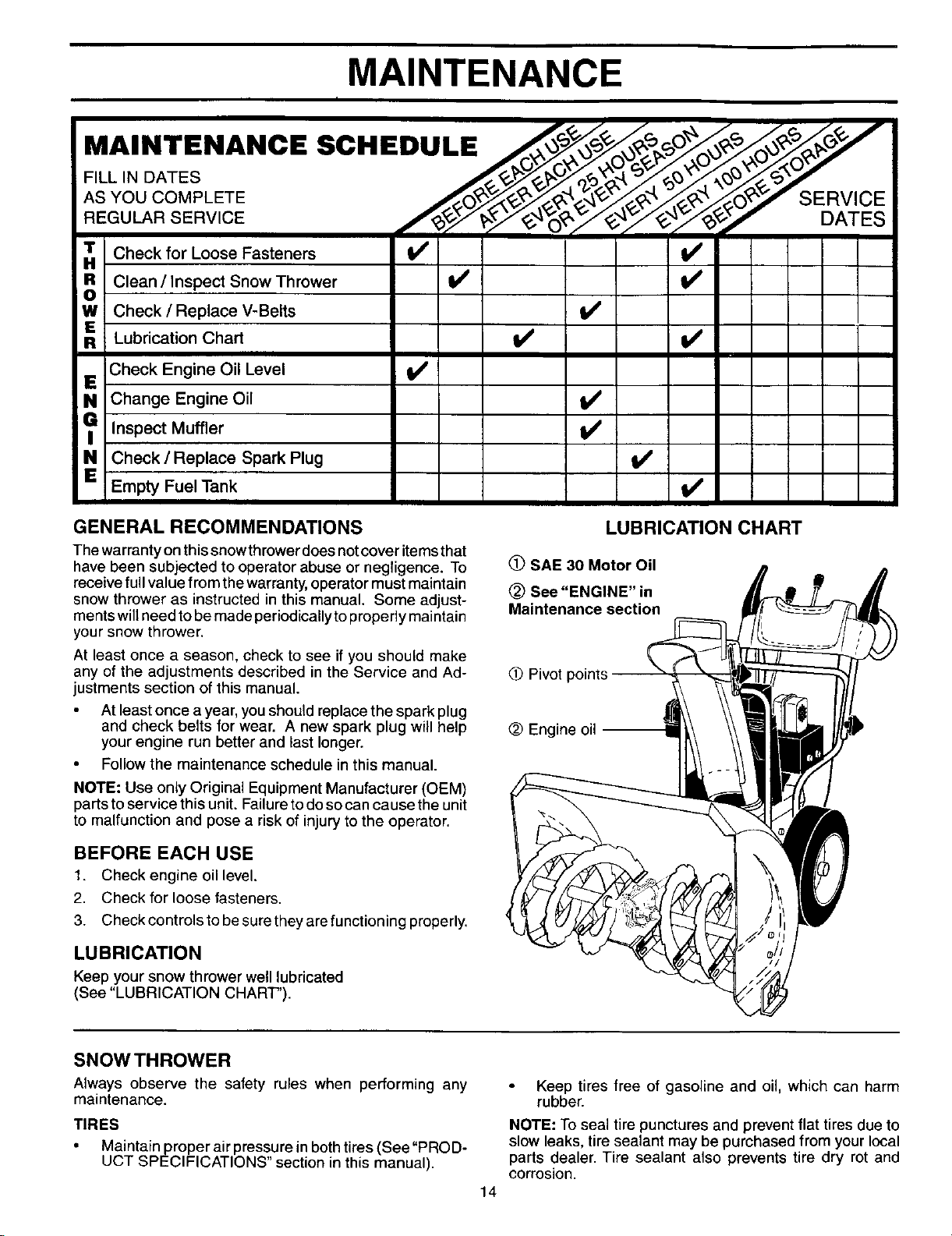
LUBRICATION CHART
(_ SAE 30 Motor Oil
See "ENGINE" in
Maintenance section
0 Pivot points
@ Engine oil
SNOW THROWER
Always observe the safety rules when performing any
maintenance.
TIRES
• Maintain proper air pressure in both tires (See "PROD-
UCT SPECIFICATIONS" section in this manual).
14
Keep tires free of gasoline and oil, which can harm
rubber.
NOTE: To seal tire punctures and prevent flat tires due to
slow leaks, tire sealant may be purchased from your local
parts dealer. Tire sealant also prevents tire dry rot and
corrosion.
MAINTENANCE
V-BELTS TO CHANGE ENGINE OIL
Check V-belts for deterioration and wear after every 50
hours of operation and replace if necessary. The belts
are not adjustable. Replace belts if they begin to slip from
wear. (See 'q-O REMOVE BELT COVER" in the Service
and Adjustments section of this manual).
The V-belts on your snow thrower are of special construction
and should be replaced byoriginal equipment manufacturer
(OEM) belts available from your nearest dealer. Using other
than OEM belts can cause personal injury or damage to
the snow thrower.
AUGER GEAR CASE
• The gear case was filled with lubricant to the proper
level at the factory. The only time the lubricant needs
attention is if service has been performed on the gear
case.
• If lubricant is required, use only Ronex ED #1 grease.
TRACTION DRIVE SYSTEM
DO NOT lubricate the drive components inside the snow
thrower. The sprockets, hex shafts, drive disc and friction
wheel require no lubrication. The bearings and bushings
are lifetime lubricated and require no maintenance.
CAUTION: Any lubricating of the above compo-
nents can cause contamination of the friction
wheel and damage to the drive system of your
snow thrower,
I
ENGINE
See engine manual.
LUBRICATION
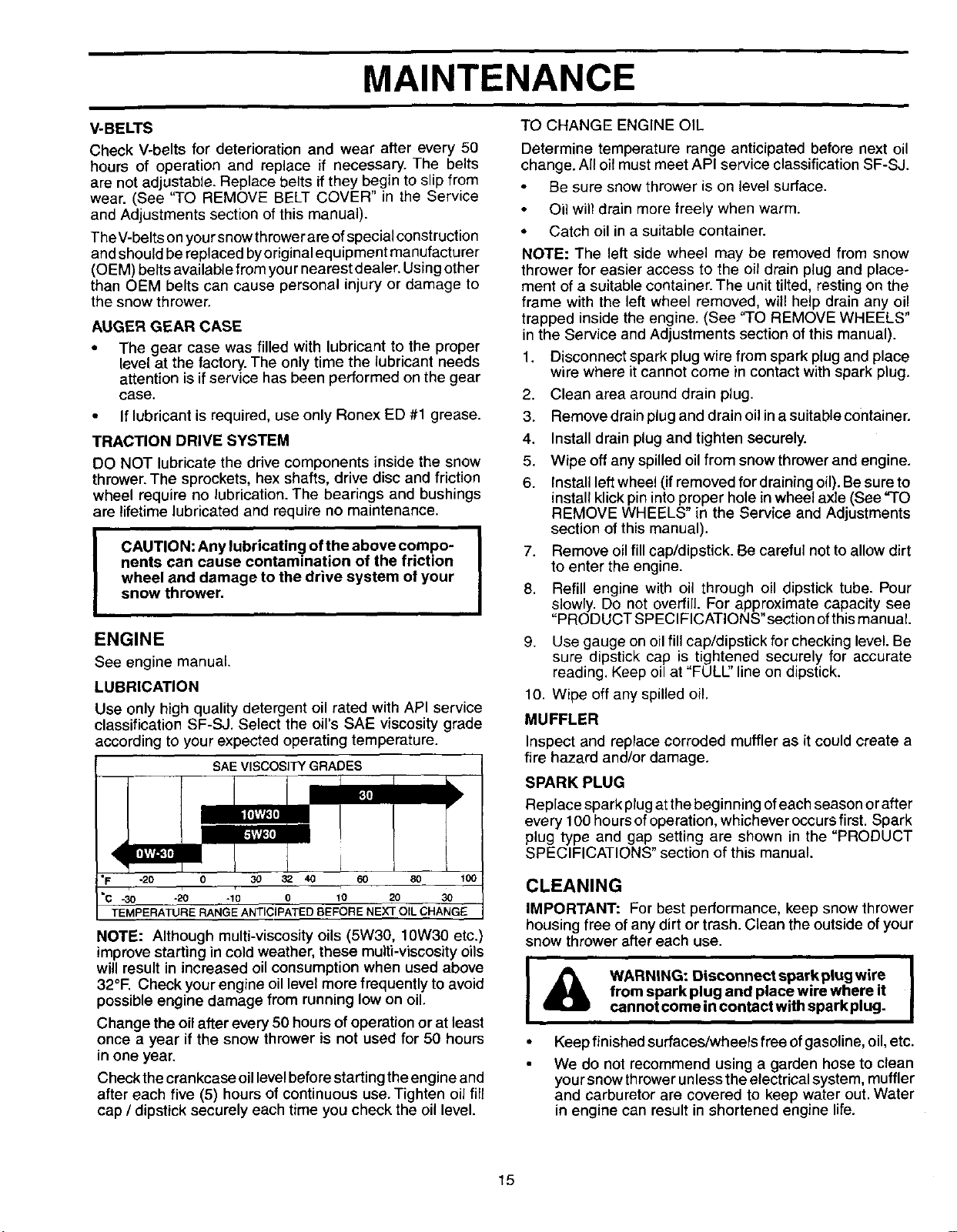
Use only high quality detergent oil rated with API service
classification SF-SJ. Select the oil's SAE viscosity grade
according to your expected operating temperature.
ill£1v#_
<
SAE VISCOSITY GRADES
nIk
.=I'¥1'_I(
"F -20 0 30 3_ 40 60 80 100
"C -30 -20 -10 0 10 20 30
TEMPERATURE RANGE ANTICIPA]'ED BEFORE NEXT OIL CHANGE
NOTE: Although multi-viscosity oils (5W30, 10W30 etc,)
improve starting in cold weather, these multi-viscosityoils
will result in increased oil consumption when used above
32°F. Check yourengine oillevel more frequently to avoid
possibleengine damage from running low on oil,
Change the oil after every 50 hours ofoperation or at least
once a year if the snow thrower is not used for 50 hours
in one year.
Check the crankcase oillevelbeforestarting theengine and
after each five (5) hours of continuous use. Tighten oil fill
cap / dipstick securely each time you check the oil level.
Determine temperature range anticipated before next oil
change. All oilmust meet API service classificationSF-SJ.
Be sure snow thrower is on level surface.
Oil will drain more freely when warm.
• Catch oil in a suitable container.
NOTE: The left side wheel may be removed from snow
thrower for easier access to the oil drain plug and place-
ment of a suitable container. The unit tilted, resting on the
frame with the left wheel removed, will help drain any oil
trapped inside the engine. (See "TO REMOVE WHEELS"
in the Service and Adjustments section of this manual).
1. Disconnect spark plug wire from spark plug and place
wire where it cannot come in contact with spark plug.
2. Clean area around drain plug.
3. Remove drain plug and drain oil in a suitable container.
4. Install drain plug and tighten securely.
5. Wipe off any spilled oil from snow thrower and engine.
6. Install left wheel (if removed for draining oil). Be sure to
install klick pin into proper hole in wheel axle (See "TO
REMOVE WHEELS" in the Service and Adjustments
section of this manual).
7. Remove oil fill cap/dipstick. Be careful not to allow dirt
to enter the engine.
8. Refill engine with oil through oil dipstick tube. Pour
slowly. Do not overfill. For approximate capacity see
"PRODUCT SPECIFICATIONS" section of this manual
9. Use gauge on oil fill cap/dipstick for checking level. Be
sure dipstick cap is tightened securely for accurate
reading. Keep oil at "FULl" line on dipstick.
10. Wipe off any spilled oil,
MUFFLER
Inspect and replace corroded muffler as it could create a
fire hazard and/or damage.
SPARK PLUG
Replace spark plug at the beginning ofeach season or after
every 100 hours of operation, whichever occurs first. Spark
plug type and gap setting are shown in the "PRODUCT
SPECIFICATIONS" section of this manual.
CLEANING
IMPORTANT: For best performance, keep snow thrower
housing free of any dirt or trash. Clean the outside of your
snow thrower after each use.
I _ WARNING: Disconnectsperkplugwire
from spark plug and place wire where it
cannot come in contact with spark plug.
Keep finished surfaces/wheels free of gasoline, oil,etc.
We do not recommend using a garden hose to clean
your snow thrower unless the electrical system, muffler
and carburetor are covered to keep water out. Water
in engine can result in shortened engine life.
15
SERVICE AND ADJUSTMENTS
&
WARNING: To avoid serious injury,
before performing any service or ad-
justments:
1. Be sure throttle is in STOP position.
2. Remove safety ignition key.
3. Make sure the augers and all moving
parts have completely stopped.
4. Disconnect spark plug wire from
spark plug and place wire where it
cannot come in contact with plug.
SNOW THROWER
TO ADJUST SNOWTHROWER HEIGHT
See "ro ADJUST SKID PLATES" and "SCRAPER BAR"
in the Operation section of this manual.
CHUTE DEFLECTOR
The chute deflector, attached to the top of the discharge
chute, is provided to direct discharging snow away from
the operator. Ifthe deflector becomes damaged, it should
be replaced.
iA w.°.,.oavo° er'ous'n'ur I
never operate your snow thrower with
the deflector removed or damaged.
Tochange direction and/or distance snow isdischarged,
see "TO CONTROL SNOW DISCHARGE" in the Op-
eration section ofthis manual.
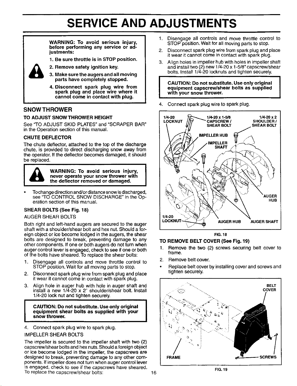
SHEAR BOLTS (See Fig. 18)
AUGER SHEAR BOLTS
Both right and left-hand augers are secured to the auger
shaft with a shoulder/shear bolt and hex nut. Should a for-
eign object or ice become lodged in the augers, the shear
bolts are designed to break, preventing damage to any
other components. If one or both augers do not turn when
auger control lever is engaged, check to see if one or both
of the bolts have sheared. To replace the shear bolts:
1. Disengage all controls and move throttle control to
STOP position. Wait for all moving parts to stop.
2. Disconnect spark plug wire from spark plug and place
it wear it cannot come in contact with spark plug.
3. Align hole in auger hub with hole in auger shaft and
install a new 1/4-20 x 2" shoulder/shear bolt. Install
1/4-20 lock nut and tighten securely.
CAUTION: Do not substitute. Use only original
equipment shear bolts as supplied with your
snow thrower.
4. Connect spark plug wire to spark plug.
IMPELLER SHEAR BOLTS
The impeller is secured to the impeller shaft with two (2)
capscrew/shear bolts and hex nuts. Should a foreign object
or ice become lodged in the impeller, the capscrews are
designed to break, preventing damage to any other com-
ponents. If impeller does not turn when auger control lever
is engaged, check to see if the capscrews have sheared.
To replace the capscrew/shear bolts:
1. Disengage all controls and move throttle control to
STOP position. Wait for all moving parts to stop.
2. Disconnect spark plug wire from spark plug and place
it wear it cannot come in contact with spark plug.
3. Align holes in impeller hub with holes in impeller shaft
and installtwo (2) new 1/4-20 x 1-5/8" capscrew/shear
bolts. Install 1/4-20 Iocknuts and tighten securely.
I
4.
I
CAUTION: Do not substitute. Use only original |
equipment capscrew/shear bolts as supplied
I
with your snow thrower.
Connect spark plug wire to spark plug.
1_0x2
SHOULDER/
SHEAR BOLT
HUB
114-20
AUGER HUB AUGER SHAFT
FIG.18
TO REMOVE BELT COVER (See Fig. 19)
1. Remove the two (2) screws securing belt cover to
frame,
2, Remove belt cover•
• Replace belt cover by installing cover and screws and
tighten securely.
/ -
FRAME
BELT
COVER
SCREWS
FIG. 19
16
SERVICE AND ADJUSTMENTS
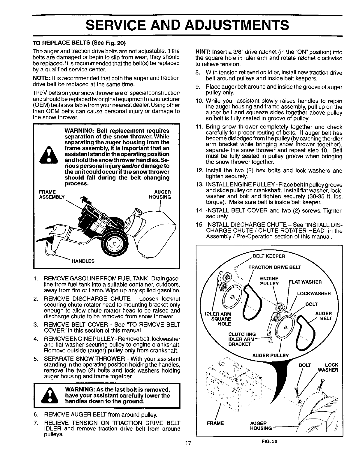
TO REPLACE BELTS (See Fig. 20)
The auger and traction drivebelts are notadjustable. Ifthe
belts are damaged or begin to slip from wear, they should
be replaced. It is recommended that the belt(s) be replaced
by a qualified service center.
NOTE: It is recommended that both the auger and traction
drive belt be replaced at the same time.
The V-belts on your snow thrower are of special construction
and should be replaced byoriginal equipment manufacturer
(O EM) belts available from your nearest dealer. Using other
than OEM belts can cause personal injury or damage to
the snow thrower.
&
WARNING: Belt replacement requires
separation of the snow thrower. While
separating the auger housing from the
frame assembly, it is important that an
assistant stand inthe operating position
and hold the snow thrower handles. Se-
rious personal injury and/or damage to
the unit could occur ifthe snow thrower
should fall during the belt changing
process.
FRAME AUGER
ASSEMBLY HOUSING
HINT: Insert a 3/8" drive ratchet (in the "ON" position) into
the square hole in idler arm and rotate ratchet clockwise
to relieve tension.
8. With tension relieved on idler, install new traction drive
belt around pulleys and inside belt keepers.
9. Place auger belt around and inside the groove of auger
pulley only.
10. While your assistant slowly raises handles to rejoin
the auger housing and frame assembly, pull up on the
auger belt and squeeze sides together above pulley
so belt is fully seated in groove of pulley.
11. Bring snow thrower completely together and check
carefully for proper routing of belts. If auger belt has
become dislodged from the pulley (by catching the idler
arm bracket while bringing snow thrower together),
separate the snow thrower and repeat step 10. Belt
must be fully seated in pulley groove when bringing
the snow thrower together.
12. Install the two (2) hex bolts and lock washers and
tighten securely.
13. INSTALL ENGINE PULLEY- Place belt in pulley groove
and slide pulley on crankshaft. Install flat washer, lock-
washer and bolt and tighten securely (30-35 ft. Ibs.
torque). Make sure belt is inside belt keeper.
14. INSTALL BELT COVER and two (2) screws. Tighten
securely.
15. INSTALL DISCHARGE CHUTE - See "INSTALL DIS-
CHARGE CHUTE / CHUTE ROTATER HEAD" in the
Assembly / Pre-Operation section of this manual.
1.
2.
3.
4.
5.
I
6.
7.
REMOVE GASOLINE FROM FUELTANK- Drain gaso-
line from fuel tank into a suitable container, outdoors,
away from fire or flame. Wipe up any spilled gasoline.
REMOVE DISCHARGE CHUTE - Loosen Iocknut
securing chute rotator head to mounting bracket only
enough to allow chute rotator head to be raised and
discharge chute to be removed from snow thrower.
REMOVE BELT COVER - See "TO REMOVE BELT
COVER" in this section of this manual.
REMOVE ENGINE PULLEY- Remove bolt, Iockwasher
and flat washer securing pulley to engine crankshaft.
Remove outside (auger) pulley only from crankshaft.
SEPARATE SNOW THROWER - With your assistant
standing in the operating position holding the handles,
remove the two (2) bolts and lock washers holding
auger housing and frame together.
I
WARNING: As the last bolt is removed, I
have your assistant carefully lower the
I
handles down to the ground.
REMOVE AUGER BELT from around pulley.
RELIEVE TENSION ON TRACTION DRIVE BELT
IDLER and remove traction drive belt from around
pulleys.
HOLE
_.: _ .-i ¸ •......
FRAME AUGER
HOUSING
LOCK
WASHER
17 FIG.20
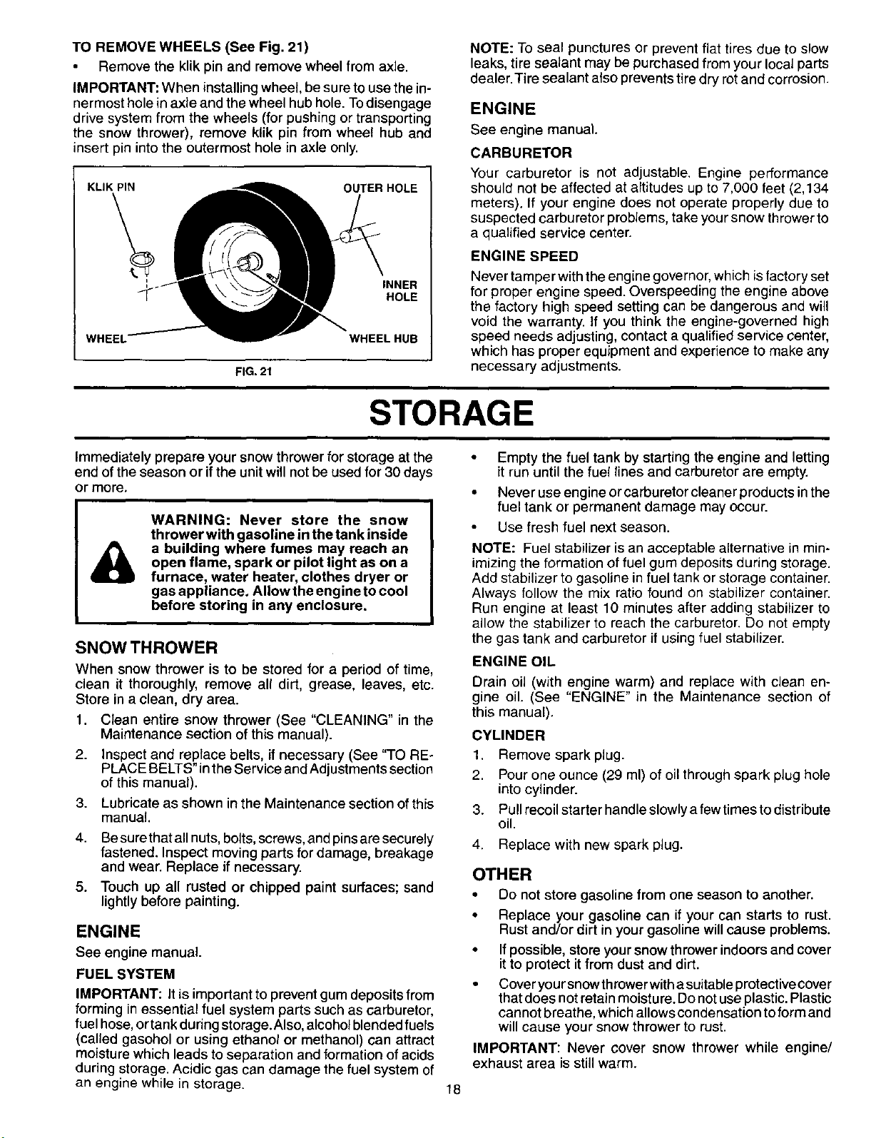
TOREMOVEWHEELS(SeeFig.21)
Remove the klik pin and remove wheel from axle.
IMPORTANT: When installing wheel, be sure to usethe in-
nermost hole in axle and the wheel hub hole. Todisengage
drive system from the wheels (for pushing or transporting
the snow thrower), remove klik pin from wheel hub and
insert pin intothe outermost hole in axle only.
KLIK PIN OUTER HOLE
INNER
HOLE
WHEEL WHEELHUB
NOTE: To seal punctures or prevent flat tires due to slow
leaks, tire sealant may be purchased from your local parts
dealer. Tire sealant also prevents tire dry rot and corrosion.
ENGINE
See engine manual.
CARBURETOR
Your carburetor is not adjustable. Engine performance
should not be affected at altitudes up to 7,000 feet (2,134
meters). If your engine does not operate properly due to
suspected carburetor problems, take your snow thrower to
a qualified service center.
ENGINE SPEED
FIG. 21
STORAGE
Never tamper with the engine governor, which is factory set
for proper engine speed. Overspeeding the engine above
the factory high speed setting can be dangerous and will
void the warranty. If you think the engine-governed high
speed needs adjusting, contact a qualified service center,
which has proper equipment and experience to make any
necessary adjustments.
Immediately prepare your snow thrower for storage at the •
end ofthe season or ifthe unitwill notbe used for 30 days
or more,
WARNING: Never store the snow
thrower with gasoline in the tank inside
a building where fumes may reach an
open flame, spark or pilot light as on a
furnace, water heater, clothes dryer or
gas appliance. Allow the engine to cool
before storing in any enclosure.
SNOW THROWER
2.
3.
4.
5.
When snow thrower is to be stored for a period of time,
clean it thoroughly, remove all dirt, grease, leaves, etc.
Store in a clean, dry area.
1. Clean entire snow thrower (See "CLEANING" in the
Maintenance section of this manual).
Inspect and replace belts, if necessary (See "TO RE-
PLACE BELTS" inthe Service andAdjustments section
of this manual).
Lubricate as shown in the Maintenance section of this
manual.
Be sure thatall nuts, bolts, screws, and pins are securely
fastened. Inspect moving parts for damage, breakage
and wear. Replace if necessary.
Touch up all rusted or chipped paint surfaces; sand
lightly before painting.
ENGINE
See engine manual.
FUEL SYSTEM
IMPORTANT: It is important to prevent gum deposits from
forming in essential fuel system parts such as carburetor,
fuel hose,ortankduring storage. Also,alcoholblended fuels
(called gasohol or using ethanol or methanol) can attract
moisture which leads to separation and formation of acids
during storage. Acidic gas can damage the fuel system of
an engine while in storage.
Empty the fuel tank by starting the engine and letting
it run until the fuel lines and carburetor are empty.
Never use engine or carburetor cleaner products in the
fuel tank or permanent damage may occur.
Use fresh fuel next season.
NOTE: Fuel stabilizer is an acceptable alternative in min-
imizing the formation of fuel gum deposits during storage.
Add stabilizer to gasoline in fuel tank or storage container.
Always follow the mix ratio found on stabilizer container.
Run engine at least 10 minutes after adding stabilizer to
allow the stabilizer to reach the carburetor. Do not empty
the gas tank and carburetor if using fuel stabilizer.
ENGINE OIL
Drain oil (with engine warm) and replace with clean en-
gine oil. (See "ENGINE" in the Maintenance section of
this manual).
CYLINDER
1.
2.
3.
4.
Remove spark plug.
Pour one ounce (29 ml) of oil through spark plug hole
into cylinder.
Pull recoil starter handle slowly afew times to distribute
oil.
Replace with new spark plug.
OTHER
• Do not store gasoline from one season to another.
• Replace your gasoline can if your can starts to rust.
Rust and/or dirt in your gasoline will cause problems.
• If possible, store your snow thrower indoors and cover
it to protect it from dust and dirt.
• Cover your snow thrower with a suitable protective cover
that does not retain moistu re.Do not use plastic. Plastic
cannot breathe, which allows condensation to form and
will cause your snow thrower to rust.
IMPORTANT: Never cover snow thrower while engine/
exhaust area is still warm.
18
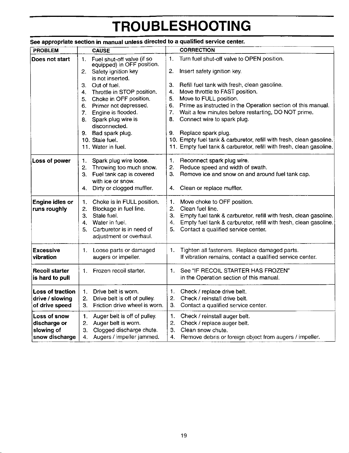
TROUBLESHOOTING
See appropriate section in manual unless directed to a qualified service center.
PROBLEM CORRECTION
Does not start 1. Turn fuel shut-off valve to OPEN position.
Loss of power
Engine idles or
runs roughly
CAUSE
1. Fuel shut-off valve (if so
equipped) in OFF position.
2. Safety ignition key
is not inserted.
3. Out of fuel.
4. Throttle in STOP position.
5. Choke in OFF position.
6. Primer not depressed.
7. Engine is flooded.
8. Spark plug wire is
disconnected.
9. Bad spark plug.
10. Stale fuel.
11. Water in fuel.
1. Spark plug wire loose.
2. Throwing too much snow.
3. Fuel tank cap is covered
with ice or snow.
4. Dirty or clogged muffler.
1. Choke is in FULL position.
2. Blockage in fuel line.
3. Stale fuel.
4. Water in fuel.
5. Carburetor is in need of
adjustment or overhaul.
2, Insert safety ignitionkey.
3. Refill fuel tank with fresh, clean gasoline.
4. Move throttle to FAST position.
5. Move to FULL position,
6. Prime as instructed in the Operation section of this manual.
7. Wait a few minutes before restarting, DO NOT prime.
8. Connect wire to spark plug.
; 9. Replace spark plug.
10. Empty fuel tank & carburetor, refill with fresh, clean gasoline.
11. Empty fuel tank & carburetor, refill with fresh, clean gasoline.
1. Reconnect spark plug wire.
2. Reduce speed and width of swath.
3. Remove ice and snow on and around fuel tank cap.
4. Clean or replace muffler.
1. Move choke to OFF position.
2. Clean fuel line.
3. Empty fuel tank & carburetor, refill with fresh, clean gasoline.
4. Empty fuel tank & carburetor, refill with fresh, clean gasoline.
5. Contact a qualified service center.
Excessive 1. Loose parts or damaged 1. Tighten all fasteners. Replace damaged parts.
vibration augers or impeller. If vibration remains, contact a qualified service center.
Recoil starter 1. Frozen recoil starter. 1. See "IF RECOIL STARTER HAS FROZEN"
is hard to pull in the Operation section of this manual.
Loss of traction 1. Drive belt is worn. 1. Check/replace drive belt.
drive / slowing 2. Drive belt is off of pulley. 2. Check / reinstall drive belt.
of drive speed 3. Friction drive wheel is worn. 3. Contact a qualified service center.
Loss of snow 1. Auger belt is off of pulley. 1. Check / reinstall auger belt.
discharge or 2. Auger belt isworn. 2. Check / replace auger belt.
slowing of 3. Clogged discharge chute. 3. Clean snow chute.
snow discharge 4. Augers / impeller jammed. 4. Remove debris or foreign object from augers / impeller.
19
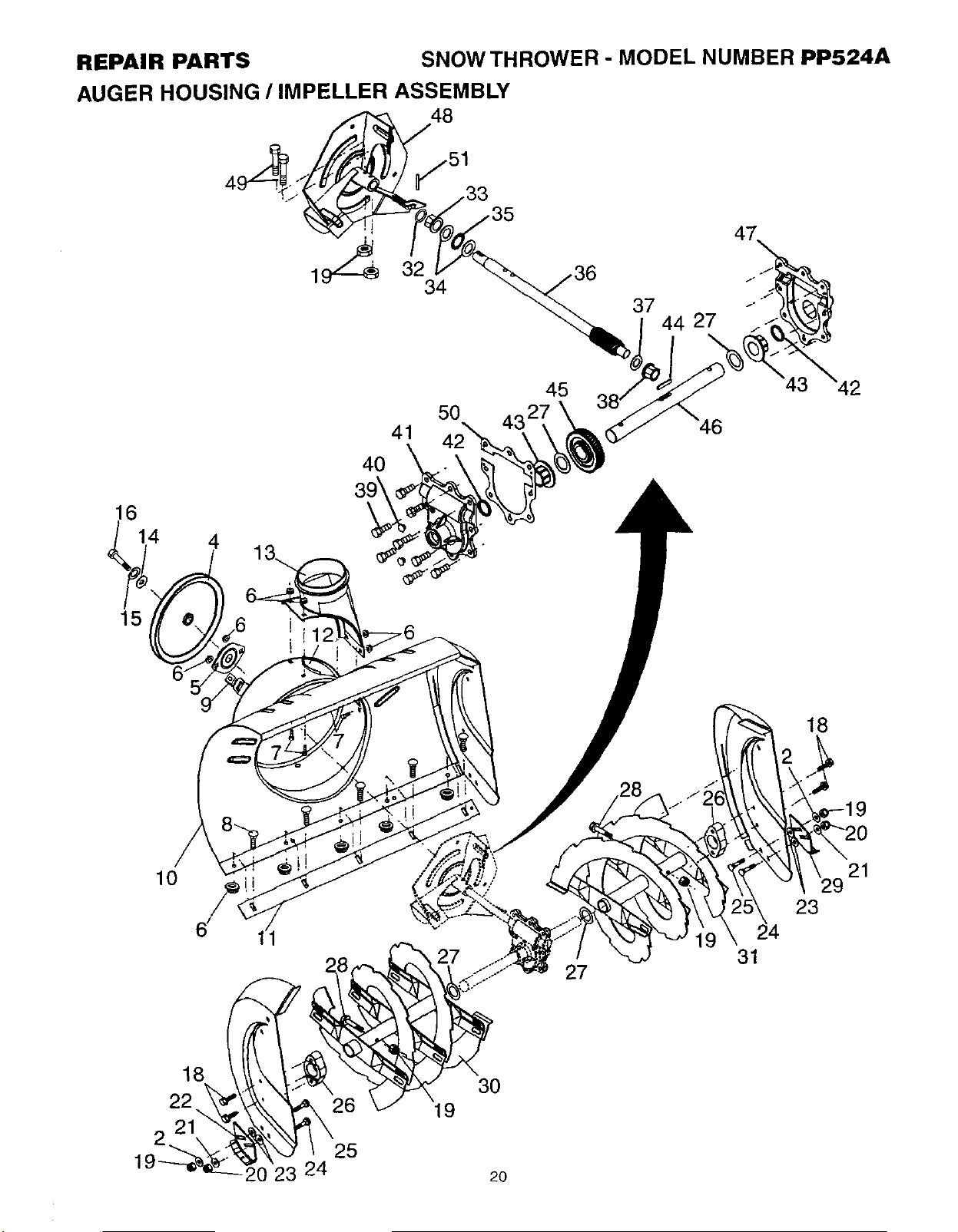
REPAIR PARTS SNOWTHROWER - MODEL NUMBER PP524A
AUGER HOUSING / IMPELLER ASSEMBLY
37
44 27
47
14 4
15
41
4O
45
5O
t
18
10
27
31
21
23
18
22
21
20 23 24
26
25
3O
19
2O
REPAIR PARTS SNOW THROWER - MODEL NUMBER PP524A
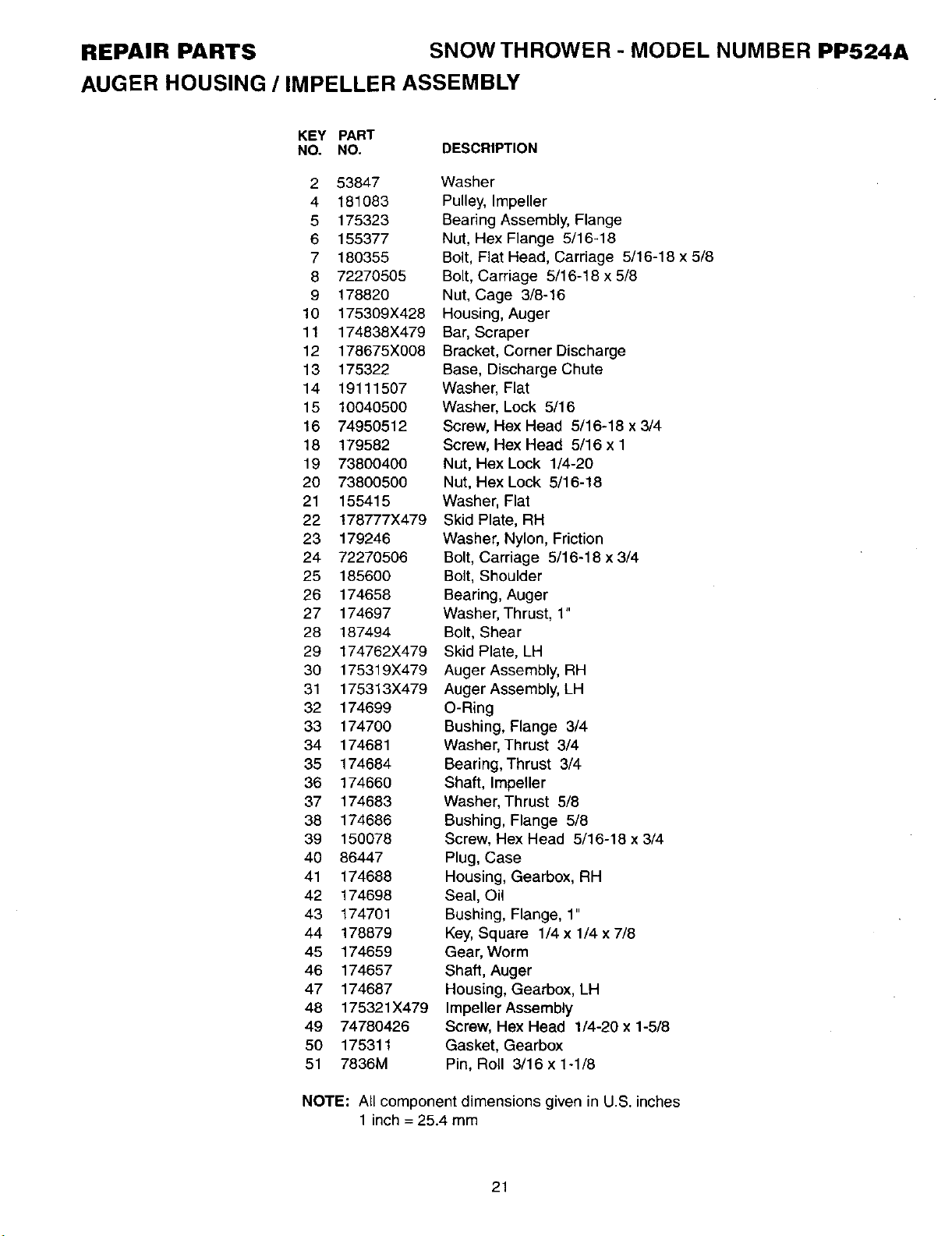
AUGER HOUSING / IMPELLER ASSEMBLY
KEY PART
NO. NO. DESCRIPTION
2 53847 Washer
4 181083 Pulley, Impeller
5 175323 Bearing Assembly, Flange
6 155377 Nut, Hex Flange 5/16-18
7 180355 Bolt, Flat Head, Carriage 5/16-18 x 5/8
8 72270505 Bolt, Carriage 5/16-18 x 5/8
9 178820 Nut, Cage 3/8-16
10 175309X428 Housing, Auger
11 174838X479 Bar, Scraper
12 178675X008 Bracket, Corner Discharge
13 175322 Base, Discharge Chute
14 19111507 Washer, Flat
15 10040500 Washer, Lock 5/16
16 74950512 Screw, Hex Head 5/16-18 x 3/4
18 179582 Screw, Hex Head 5/16 x 1
19 73800400 Nut, Hex Lock 1/4-20
20 73800500 Nut, Hex Lock 5/16-18
21 155415 Washer, Flat
22 178777X479 Skid Plate, RH
23 179246 Washer, Nylon, Friction
24 72270506 Bolt, Carriage 8/16-18 x 3/4
25 185600 Bolt, Shoulder
26 174658 Bearing, Auger
27 174697 Washer, Thrust, 1"
28 187494 Bolt, Shear
29 174762X479 Skid Plate, LH
30 175319X479 Auger Assembly, RH
31 175313X479 Auger Assembly, LH
32 174699 O-Ring
33 174700 Bushing, Flange 3/4
34 174681 Washer, Thrust 3/4
35 174684 Bearing, Thrust 3/4
36 174660 Shaft, Impeller
37 174683 Washer, Thrust 5/8
38 174686 Bushing, Flange 5/8
39 150078 Screw, Hex Head 5/16-18 x 3/4
40 86447 Plug, Case
41 174688 Housing, Gearbox, RH
42 174698 Seal, Oil
43 174701 Bushing, Flange, 1"
44 178879 Key, Square 1/4 x 1/4 x 7/8
45 174659 Gear, Worm
46 174657 Shaft, Auger
47 174687 Housing, Gearbox, LH
48 175321X479 Impeller Assembly
49 74780426 Screw, Hex Head 1/4-20 x 1-5/8
50 175311 Gasket, Gearbox
51 7836M Pin, Roll 3/16 x 1-1/8
NOTE: All component dimensions given in U.S. inches
1 inch = 25.4 mm
21
REPAIR PARTS SNOWTHROWER - MODEL NUMBER PP524A
CONTROL PANEL / DISCHARGE CHUTE
19
\
\
_14
2
2
\
26
't \
\
\
\
\
_--'" 27
25
29
8
27
- \
4
7
8
16
22
13
14
311
21
14
10
9
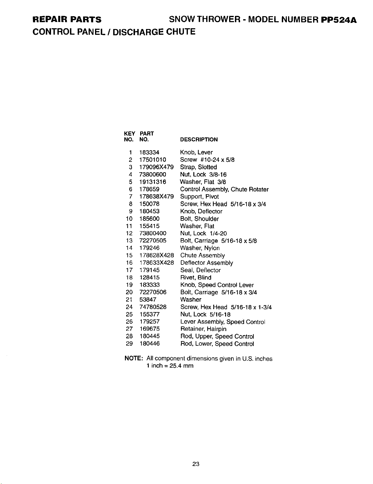
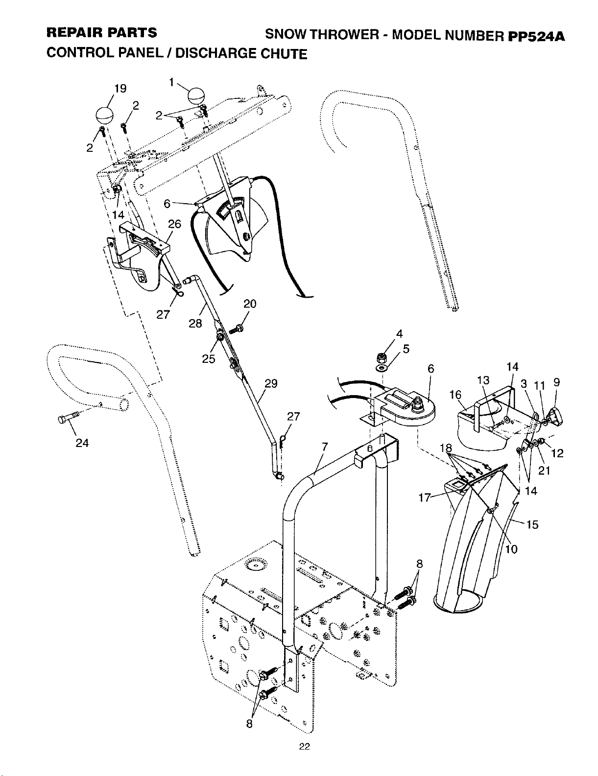
REPAIR PARTS SNOW THROWER - MODEL NUMBER PP524A
CONTROL PANEL / DISCHARGE CHUTE
KEY PART
NO. NO. DESCRIPTION
1 183334
2 17501010
3 179096X479
4 73800600
5 19131316
6 178659
7 178638X479
8 150078
9 180453
10 185600
11 155415
12 73800400
13 72270505
14 179246
15 178628X428
16 178633X428
17 179145
18 128415
19 183333
20 72270506
21 53847
24 74780528
25 155377
26 179257
27 169675
28 180445
29 180446
Knob, Lever
Screw #10-24 x 5/8
Strap, Slotted
Nut, Lock 3/8-16
Washer, Flat 3/8
Control Assembly, Chute Rotater
Support, Pivot
Screw, Hex Head 5/16-18 x 3/4
Knob, Deflector
Bolt, Shoulder
Washer, Flat
Nut, Lock 1/4-20
Bolt, Carriage 5/16-18 x 5/8
Washer, Nylon
Chute Assembly
Deflector Assembly
Seal, Deflector
Rivet, Blind
Knob, Speed Control Lever
Bolt, Carriage 5/16-18 x 3/4
Washer
Screw, Hex Head 5/16-18 x 1-3/4
Nut, Lock 5/16-18
Lever Assembly, Speed Control
Retainer, Hairpin
Rod, Upper, Speed Control
Rod, Lower, Speed Control
NOTE: All component dimensions given in U.S. inches
1 inch = 25.4 mm
23
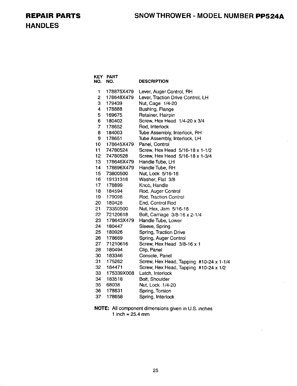
REPAIR PARTS
HANDLES
SNOW THROWER- MODEL NUMBER PP524A
2
4
5
\,
\, 15
14
\
12
11
17
32
17
31
23
\
\
\
24
\
22 \
26
22
\
\
\ 24
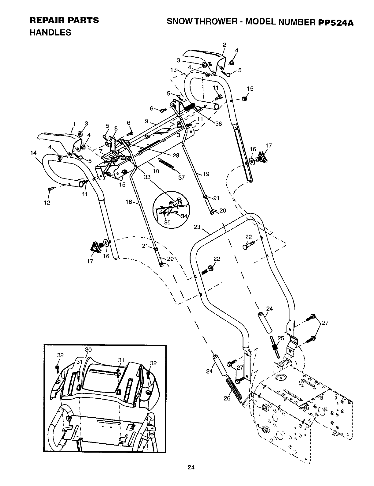
REPAIR PARTS
HANDLES
SNOWTHROWER - MODEL NUMBER PP524A
KEY PART
NO. NO.
1 178875X479
2 178648X479
3 179439
4 178888
5 169675
6 180402
7 178652
8 184003
9 178651
10 178645X479
11 74780524
12 74780528
13 178646X479
14 178696X479
15 73800500
16 19131316
17 178899
18 184594
19 179098
20 180428
21 73350500
22 72120618
23 178643X479
24 180447
25 180926
26 178669
27 71210616
28 180494
30 183346
31 175262
32 184471
33 175339X008
34 183518
35 68038
36 178831
37 178658
DESCRIPTION
Lever, Auger Control, RH
Lever, Traction Drive Control, LH
Nut, Cage 1/4-20
Bushing, Flange
Retainer, Hairpin
Screw, Hex Head 1/4-20 x 3/4
Rod, Interlock
Tube Assembly, Interlock, RH
Tube Assembly, Interlock, LH
Panel, Control
Screw, Hex Head 5/16-18 x 1-1/2
Screw, Hex Head 5/16-18 x 1-3/4
Handle Tube, LH
Handle Tube, RH
Nut, Lock 5/16-18
Washer, Flat 3/8
Knob, Handle
Rod, Auger Control
Rod, Traction Control
End, Control Rod
Nut, Hex, Jam 5/16-18
Bolt, Carriage 3/8-16 x 2-1/4
Handle Tube, Lower
Sleeve, Spring
Spring, Traction Drive
Spring, Auger Control
Screw, Hex Head 3/8-16 x 1
Clip, Panel
Console, Panel
Screw, Hex Head, Tapping #10-24 x 1-1/4
Screw, Hex Head, Tapping #10-24 x 1/2
Latch, Interlock
Bolt, Shoulder
Nut, Lock 1/4-20
Spring, Torsion
Spring, Interlock
NOTE: All component dimensions given in U.S. inches
1 inch = 25.4 mm
25
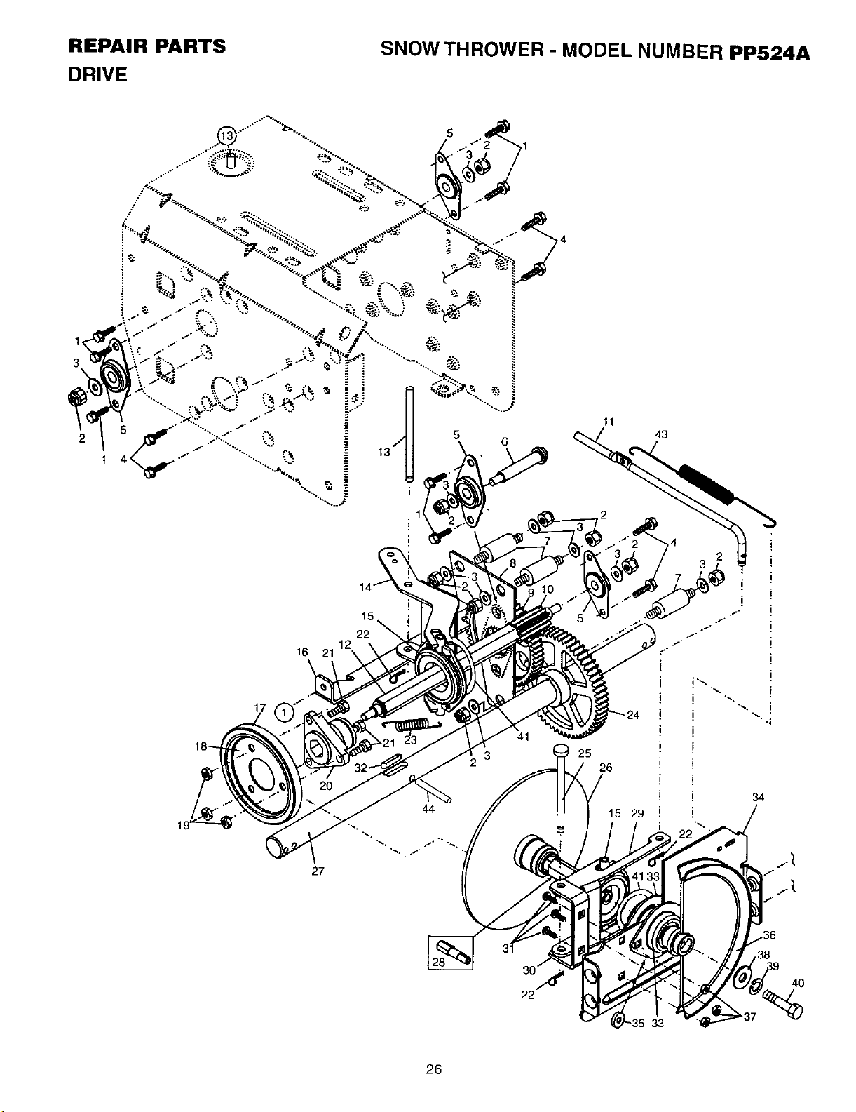
REPAIR PARTS
DRIVE
SNOW THROWER - MODEL NUMBER PP524A
1,1
3
5
6
16 21
17
22
11
25
26
43
33
4O
26
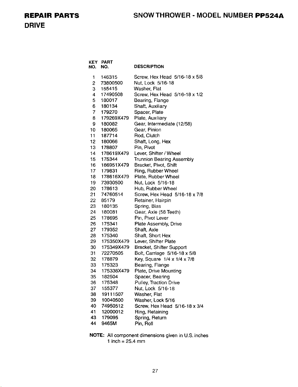
REPAIR PARTS
DRIVE
SNOWTHROWER - MODEL NUMBER PP524A
KEY PART
NO. NO.
1 146315
2 73800500
3 155415
4 17490508
5 180017
6 180134
7 179270
8 179269X479
9 180082
10 180065
11 187714
12 180066
13 178807
14 178619X479
15 175344
16 186951X479
17 179831
16 178616X479
19 73930500
20 178613
21 74760514
22 85179
23 180135
24 180081
25 178695
26 175341
27 179352
28 175340
29 175350X479
30 175349X479
31 72270505
32 178879
33 175323
34 175338X479
35 182504
36 175348
37 155377
38 19111507
39 10040500
40 74950512
41 12000012
43 179095
44 9465M
DESCRIPTION
Screw, Hex Head 5/16-18 x 5/8
Nut, Lock 5/16-18
Washer, Flat
Screw, Hex Head 5/16-18 x 1/2
Bearing, Flange
Shaft, Auxiliary
Spacer, Plate
Plate, Auxiliary
Gear, Intermediate (12/58)
Gear, Pinion
Rod, Clutch
Shaft, Long, Hex
Pin, Pivot
Lever, Shifter / Wheel
Trunnion Bearing Assembly
Bracket, Pivot, Shift
Ring, Rubber Wheel
Plate, Rubber Wheel
Nut, Lock 5/16-18
Hub, Rubber Wheel
Screw, Hex Head 5/16-18 x 7/8
Retainer, Hairpin
Spring, Bias
Gear, Axle (58 Teeth)
Pin, Pivot Lever
Plate Assembly, Drive
Shaft, Axle
Shaft, Short Hex
Lever, Shifter Plate
Bracket, Shifter Support
Bolt, Carriage 5/16-18 x 5/8
Key, Square 1/4 x 1/4 x 7/8
Bearing, Flange
Plate, Drive Mounting
Spacer, Bearing
Pulley, Traction Drive
Nut, Lock 5/16-18
Washer, Flat
Washer, Lock 5/16
Screw, Hex Head 5/16-18 x 3/4
Ring, Retaining
Spring, Return
Pin, Roll
NOTE: All component dimensions given in U.S. inches
1 inch = 25.4 mm
27
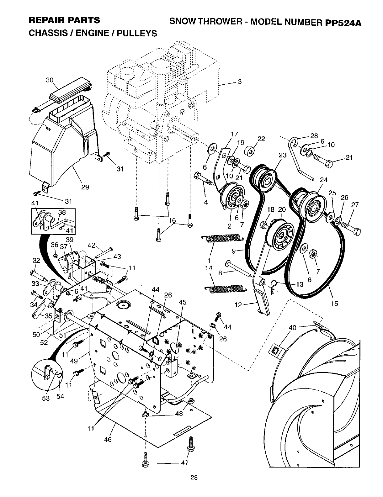
REPAIR pARTS
cHAsSiS I ENG|HE I pULLEYS
3O
41
29
32
44
26
45
22
2
1
52
11
53 54
46
28
24
7
6
REPAIR PARTS SNOW THROWER - MODEL NUMBER PP524A
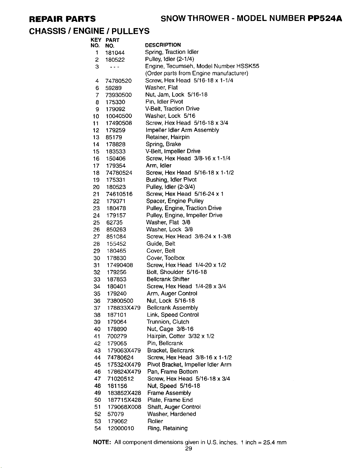
CHASSIS / ENGINE / PULLEYS
KEY PART
NO. NO,
1 181044
2 180522
3 - - -
4 74780520
6 59289
7 73930500
8 175330
9 179092
10 10040500
11 17490508
12 179259
13 85179
14 178828
15 183533
16 150406
17 179354
18 74780524
19 175331
20 180523
21 74610516
22 179371
23 180478
24 179157
25 62735
26 850263
27 851084
28 155452
29 180465
30 178830
31 17490408
32 179256
33 187853
34 180401
35 179240
36 73800500
37 178833X479
38 187101
39 179064
40 178890
41 700279
42 179065
43 179063X479
44 74780624
45 175324X479
46 178624X479
47 71020512
48 181156
49 183852X428
50 187715X428
51 179068X008
52 57079
53 179062
54 12000010
DESCRIPTION
Spring, Traction Idler
Pulley, Idler (2-1/4)
Engine, Tecumseh, Model Number HSSK55
(Order parts from Engine manufacturer)
Screw, Hex Head 5/16-18 x 1-1/4
Washer, Flat
Nut, Jam, Lock 5/16-18
Pin, Idler Pivot
V-Belt, Traction Drive
Washer, Lock 5/16
Screw, Hex Head 5/16-18 x 3/4
Impeller Idler Arm Assembly
Retainer, Hairpin
Spring, Brake
V-Belt, Impeller Drive
Screw, Hex Head 3/8o16 x 1-1/4
Arm, Idler
Screw, Hex Head 5/16-18 x 1-1/2
Bushing, Idler Pivot
Pulley, Idler (2-3/4)
Screw, Hex Head 5/16-24 x 1
Spacer, Engine Pulley
Pulley, Engine, Traction Drive
Pulley, Engine, Impeller Drive
Washer, Flat 3/8
Washer, Lock 3/8
Screw, Hex Head 3/8-24 x 1-3/8
Guide, Belt
Cover, Belt
Cover, Toolbox
Screw, Hex Head 1/4-20 x 1/2
Bolt, Shoulder 5/16-18
Bellcrank Shifter
Screw, Hex Head 1/4-28 x 3/4
Arm, Auger Control
Nut, Lock 5/16-18
Bellcrank Assembly
Link, Speed Control
Trunnion, Clutch
Nut, Cage 3/8-16
Hairpin, Cotter 3/32 x 1/2
Pin, Bellcrank
Bracket, Bellcrank
Screw, Hex Head 3/8-16 x 1-1/2
Pivot Bracket, Impeller Idler Arm
Pan, Frame Bottom
Screw, Hex Head 5/16-18 x 3/4
Nut, Speed 5/16-18
Frame Assembly
Plate, Frame End
Shaft, Auger Control
Washer, Hardened
Roller
Ring, Retaining
NOTE: All component dimensions given in U.S. inches. 1 inch -- 25.4 mm
29
REPAIR PARTS
WHEELS / DECALS
SNOW THROWER - MODEL NUMBER PP524A
2
1
4
5
3
C
5
9
8
6
7
1 3
3O
REPAIR PARTS
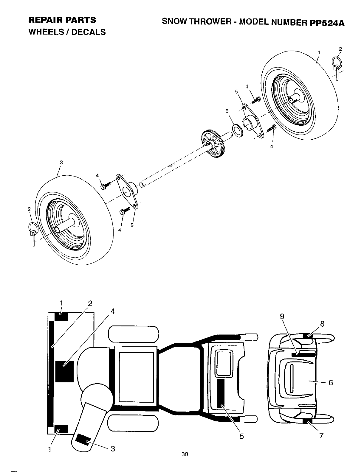
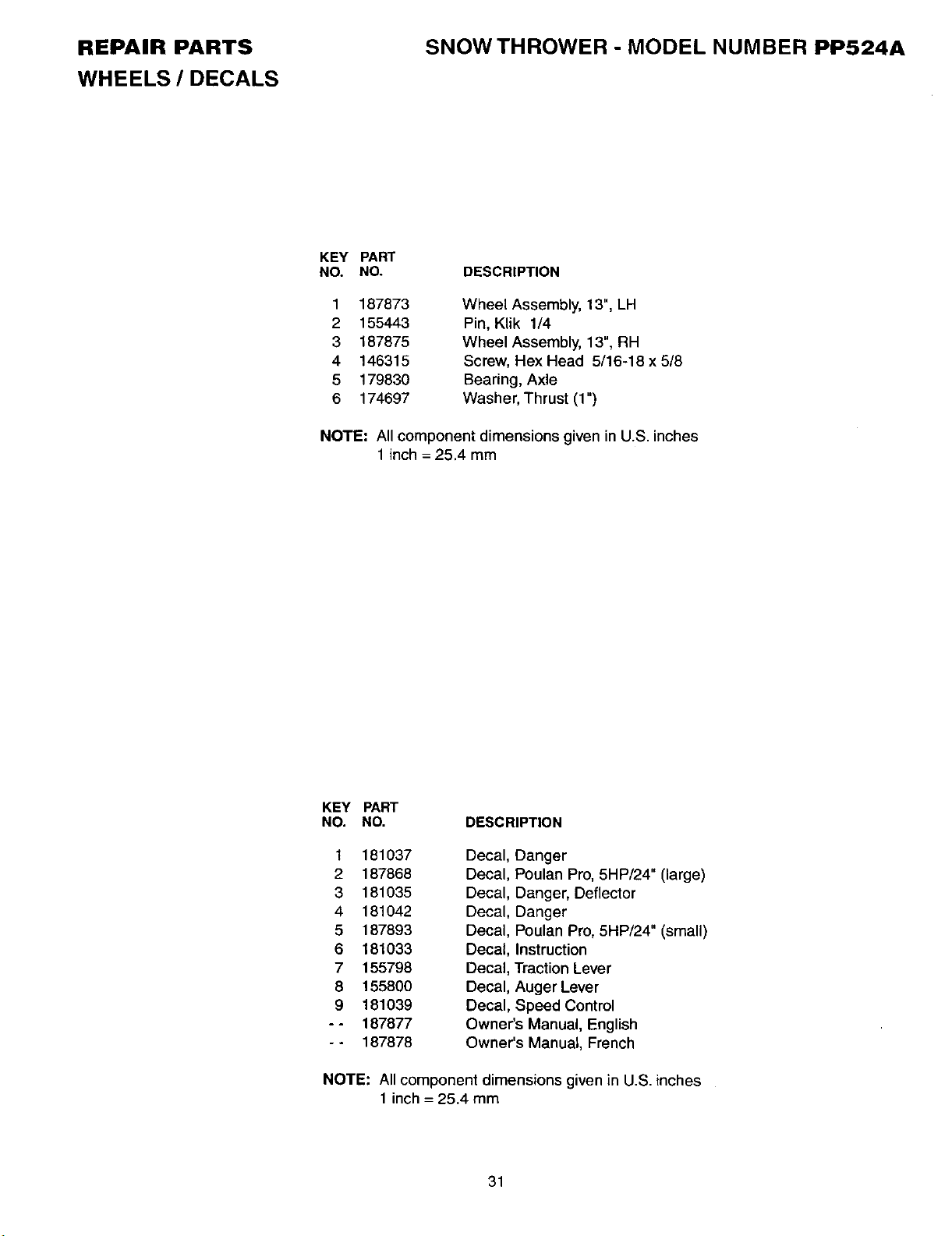
WHEELS / DECALS
SNOW THROWER - MODEL NUMBER PP524A
KEY PART
NO. NO.
1 187873
2 155443
3 187875
4 146315
5 179830
6 174697
DESCRIPTION
Wheel Assembly, 13", LH
Pin, Klik 1/4
Wheel Assembly, 13", RH
Screw, Hex Head 5/16-18 x 5/8
Bearing, Axle
Washer, Thrust (1")
NOTE: All component dimensions given in U.S. inches
1 inch = 25.4 mm
KEY PART
NO. NO. DESCRIPTION
1
2
3
4
5
6
7
8
9
181037
187868
181035
181042
187893
181033
155798
155800
181039
187877
187878
Decal, Danger
Decal, Poulan Pro, 5HP/24" (large)
Decal, Danger, Deflector
Decal, Danger
Decal, Poulan Pro, 5HP/24" (small)
Decal, Instruction
Decal, Traction Lever
Decal, Auger Lever
Decal, Speed Control
Owner's Manual, English
Owner's Manual, French
NOTE: All component dimensions given in U.S. inches
1 inch = 25.4 mm
31
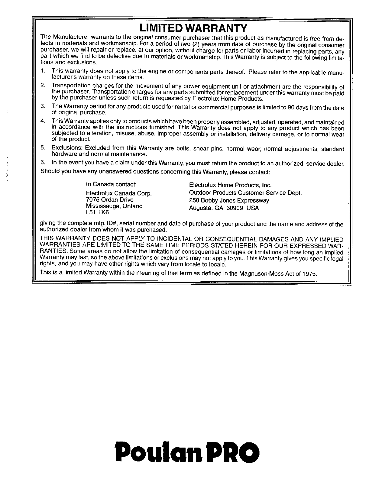
LIMITED WARRANTY
The Manufacturer warrants to the original consumer purchaser that this product as manufactured is free from de-
fects in materials and workmanship. For a period of two (2) years from date of purchase by the original consumer
purchaser, we will repair or replace, at our option, without charge for parts or labor incurred in replacing parts, any
part which we find to be defective due to materials or workmanship. This Warranty is subject to the following limita-
tions and exclusions.
1. This warranty does not apply to the engine or components parts thereof. Please refer to the applicable manu-
facturer's warranty on these items.
2. Transportation charges for the movement of any power equipment unit or attachment are the responsibility of
the purchaser. Transportation charges for any parts submitted for replacement under this warranty must be paid
by the purchaser unless such return is requested by Electrolux Home Products.
3. The Warranty period for any products used for rental or commercial purposes is limited to 90 days from the date
of original purchase.
4. This Warranty applies only to products which have been properly assembled, adjusted, operated, and maintained
in accordance with the instructions furnished. This Warranty does not apply to any product which has been
subjected to alteration, misuse, abuse, improper assembly or installation, delivery damage, or to normal wear
of the product.
5. Exclusions: Excluded from this Warranty are belts, shear pins, normal wear, normal adjustments, standard
hardware and normal maintenance.
6. In the event you have a claim under this Warranty, you must return the product to an authorized service dealer.
Should you have any unanswered questions concerning this Warranty, please contact:
In Canada contact:
Electrolux Canada Corp.
7075 Ordan Drive
Mississauga, Ontario
L5T 1K6
Electmlux Home Products, Inc.
Outdoor Products Customer Service Dept.
250 Bobby Jones Expressway
Augusta, GA 30909 USA
giving the complete mfg. ID#, serial number and date of purchase of your product and the name and address of the
authorized dealer from whom it was purchased.
THIS WARRANTY DOES NOT APPLY TO INCIDENTAL OR CONSEQUENTIAL DAMAGES AND ANY IMPLIED
WARRANTIES ARE LIMITED TO THE SAME TIME PERIODS STATED HEREIN FOR OUR EXPRESSED WAR-
RANTIES. Some areas do not allow the limitation of consequential damages or limitations of how long an implied
Warranty may last, so the above limitations or exclusions may not apply to you.This Warranty gives you specific legal
rights, and you may have other rights which vary from locale to locale.
This is a limited Warranty within the meaning of that term as defined in the Magnuson-Moss Act of 1975.
PoulanPRO