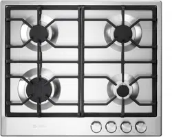
BUILT-IN GAS COOKTOPS
for residential use only
THIS COOKTOP IS FOR RESIDENTIAL USE ONLY
FOR INSTALLER ONLY
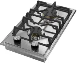
Models: VDGCT212F..
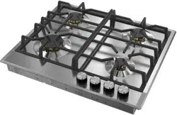
VDGCT424FSS
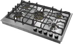
VDGCT530FSS
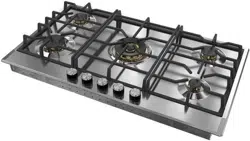
VDGCT536FSS
INSTALLATION INSTRUCTIONS
IMPORTANT - PLEASE READ AND FOLLOW
• Beforebeginning,pleasereadtheseinstructionscompletelyandcarefully.
• Donotremovepermanentlyafxedlabels,warnings,orplatesfromtheproduct.Thismay
voidthewarranty.
• Pleaseobservealllocalandnationalcodesandordinances.
• Pleaseensurethatthisproductisproperlygrounded.
• Theelectricalplugshouldalwaysbeaccessible.
• The installer should leave these instructions with the consumer who should retain
for local inspector’s use and for future reference.
Installationmustconformwithlocalcodesorintheabsenceofcodes,theNationalFuelGas
CodeANSIZ223.1/NFPA54-Iatestedition.Electricalinstallationmustbeinaccordancewith
theNationalElectricalCode,ANSI/NFPA70-latesteditionand/orlocalcodes.
INCANADA:InstallationmustbeinaccordancewiththecurrentCAN/CGA-B149.1National
GasInstallationCodeorCAN/CGA-B149.2,PropaneInstallationCodeand/orlocalcodes.
ElectricalinstallationmustbeinaccordancewiththecurrentCSAC22.1CanadianElectrical
CodesPart1and/orlocalcodes.
INSTALLATIONINMANUFACTURED(MOBILE)HOME:Theinstallationmustconformwith
theManufacturedHomeConstructionandSafetyStandard,Title24CFR,Part3280[formerly
theFederalStandardforMobileHomeConstructionandSafety,Title24,HUD(Part280)]or,
when such standard is notapplicable,theStandardforManufacturedHomeInstallations,
ANSI/NCSBCSA225.1,orwithlocalcodeswhereapplicable.
INSTALLATIONINRECREATIONALPARKTRAILERS:Theinstallationmustconformwith
stateorothercodesor,intheabsenceofsuchcodes,withtheStandardforRecreationalPark
Trailers,ANSIA119.5.
Installationofanygas-redequipmentshouldbemadebyalicensedplumber.Amanualshut-
offvalvemustbeinstalledinanaccessiblelocationinthegaslineexternaltotheappliance
forthepurposeofturningonorshuttingoffgastotheappliance(InMassachusettssuchshut-
offdevicesshouldbeapprovedbytheBoardofStateExaminersofPlumbers&GasFitters).
Ifanexternalelectricalsourceisutilized,theappliance,wheninstalled,mustbeelectrically
groundedinaccordancewithlocalcodesor,intheabsenceoflocalcodes,withthenational
ElectricalCode,ANSI/NFPA70.
Some models are supplied with a protective lm on steel and aluminium
parts.Thislmmustberemovedbeforeinstalling/usingtheappliance.
R
2
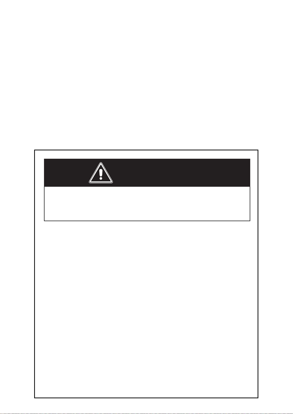
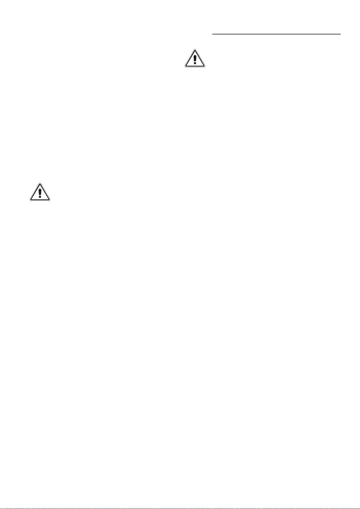
– Donotstoreorusegasolineorotherammablevaporsand
liquids in the vicinity of this or any other appliance.
– NEVER use this appliance as a space heater to heat or
warmtheroom.Doingsomayresultincarbonmonoxide
poisoningandoverheatingoftheappliance.
– WHAT TO DO IF YOU SMELL GAS:
• Donottrytolightanyappliance.
• Do not touch any electrical switch.
• Donotuseanyphoneinyourbuilding.
• lmmediately call your gas supplier from a neighbor’s
phone.Followthegassupplier’sinstructions.
• lf you cannot reach your gas supplier, call the re
department.
– Installationand service mustbe performed bya qualied
installer,serviceagency,orthegassupplier.
Iftheinformationinthismanualisnotfollowedexactly,
areorexplosionmayresultcausingpropertydamage,
personalinjury,ordeath.
WARNING !
3
CONVERSIONLABEL
DATAPLATE
This appliance is designed and manufactured solely for the cooking of domestic (household)
foodandinnotsuitableforanynonedomesticapplicationandthereforeshouldnotbeusedina
commercialenvironment.
Theappliancewarrantywillbevoidiftheapplianceisusedwithinanonedomesticenvironmenti.e.
asemicommercial,commercialorcommunalenvironment.
WARNING: This product can expose you to chemicals including
formaldehyde, which is known to the State of California to cause cancer,
and lead, which is known to the State of California to cause birth defects or other
reproductive harm. For more information go to www. P65Warnings.ca.gov.
4
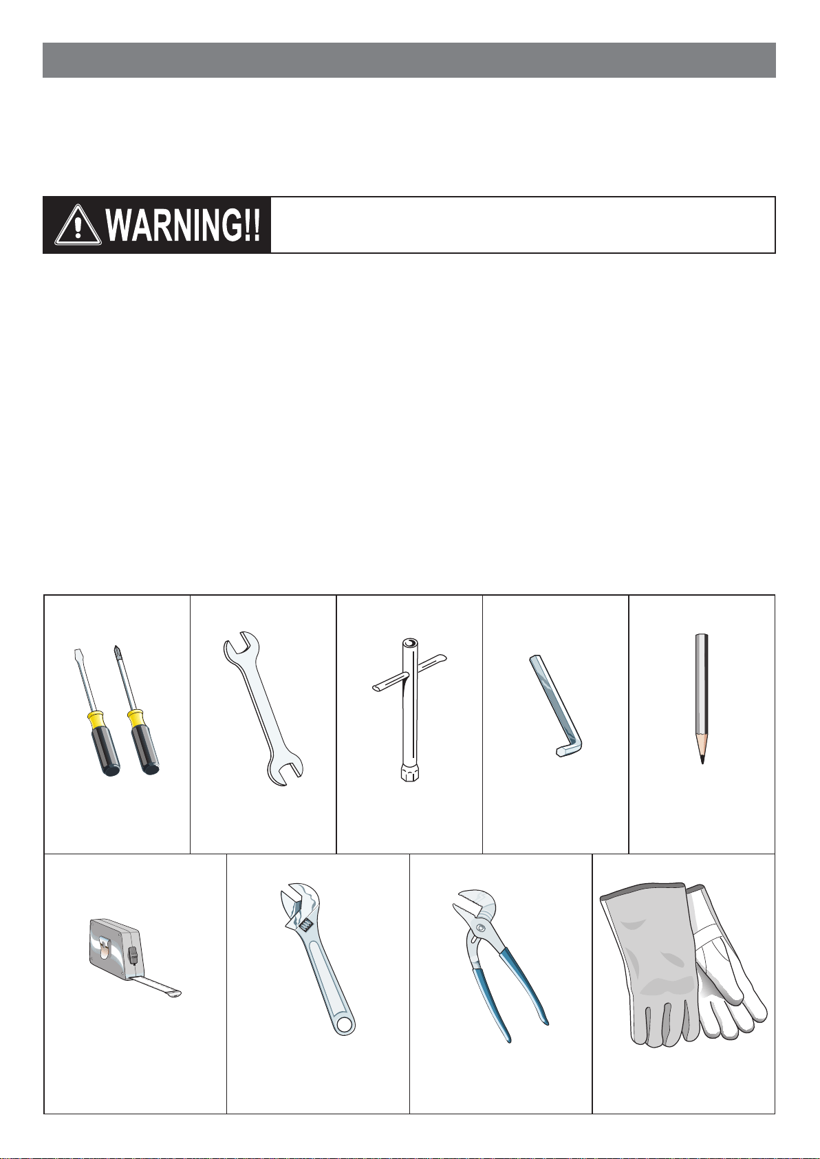
TOOLS NEEDED FOR INSTALLATION (NOT SUPPLIED WITH THE APPLIANCE)
INSTALLATION INSTRUCTIONS
WARNING!
THIS APPLIANCE MUST BE INSTALLED BY A QUALIFIED INSTALLER.
Improperinstallation,adjustment,alteration,services,ormaintenancecancauseinjuryorpropertydamage.Consulta
qualiedinstaller,serviceagent,orthegassupplier.
IMPORTANT:Theuseofsuitableprotectiveclothing/glovesis
recommendedwhenhandling,installingofthisappliance.
Screwdriver Wrench
T-handle
wrench
Tape
measure
Angled
hexagon key Pencil
Adjustable
pliers
Adjustable
wrench
Suitable protective
gloves
5
GENERAL INFORMATION
1. Installationmustconformwithlocalcodesor,intheabsence
of local codes, with the National Fuel Gas Code, ANSI
Z223.1/NFPA54
-LatestEdition,CAN/CGA-B149.1orCAN/
CGA-B149.2.
2. Installationinmanufactured(mobile)home:installationmust
conform with the Manufactured Home Construction and
Safety Standard, Title 24 CFR, Part 3280 [formerly the
Federal Standard for Mobile Home Construction and
Safety, Title 24, HUD (Part 280)] or, when such standard
is not applicable, the Standard for Manufactured Home
Installations, ANSI/NCSBCS A225.1, or with local codes
whereapplicable.
3. Installation in Recreational Park Trailers: installation must
conformwithstateorothercodesor,intheabsenceofsuch
codes, with the Standard for Recreational Park Trailers,
ANSI A119.5.
4.
WARNING!!
Thisapplianceshallnotbeusedforspaceheating.This
informationisbasedonsafetyconsiderations.
5. AlIopeningsinthewallbehindtheapplianceandintheoor
undertheapplianceshallbesealed.
6. Keep appliance area clear and free from combustible
materials,gasoline,andotherammablevapors.
7. Donotobstructtheowofcombustionandventilationair.
8. Disconnect the electrical supply to the appliance before
servicing.
9. Whenremovingapplianceforcleaningand/orservice;
A. Shutoffgasatmainsupply.
B. DisconnectACpowersupply.
C. Disconnectgaslinetotheinletpipe.
D. Carefullyliftapplianceoutofcabinetcutout.
CAUTION:Theapplianceisheavy;usecareinhandling.
10.
Electrical Requirement
Electrical installation should comply with national and local
codes.
11.
Air Supply and Ventilation
Theinstallermustreferstolocal/nationalcodes.
12.
Gas Manifold Pressure
Naturalgas-4.0”W.C.P.
LP/Propane-11.0”W.C.P.
WARNING!!
ELECTRICAL GROUNDING INSTRUCTIONS
The cooktop must be electrically grounded in accordance
withlocal codes or, in the absenceof localcodes,with the
NationalElectricalCode,ANSI/NFPANo.70-latestedition,in
Canada Canadian Electrical Code.
InstallationshouldbemadebyaIicensedelectrician.
FOR PERSONAL SAFETY, THIS APPLIANCE MUST BE
PROPERLY GROUNDED.
Ifanexternalelectricalsourceisutilized,theinstallationmustbe
electrically grounded in accordance with local codes or, in the
absenceof local codes,withthenationalElectricalCode,ANSI/
NFPA70.
This appliance is equipped with a three-prong grounding plug
(NEMA 5-15P) for your protection against shock hazard and
shouldbepluggeddirectlyintoaproperlygroundedsocket.
Do not under any circumstances cut or remove the third
(ground)prongfromthepowerplug.
REPLACEMENT PARTS
Only authorized replacement parts may be used in performing
service on the appliance. Replacement parts are available from
factory authorized parts distributors. Contact the nearest parts
distributorinyourarea.
6
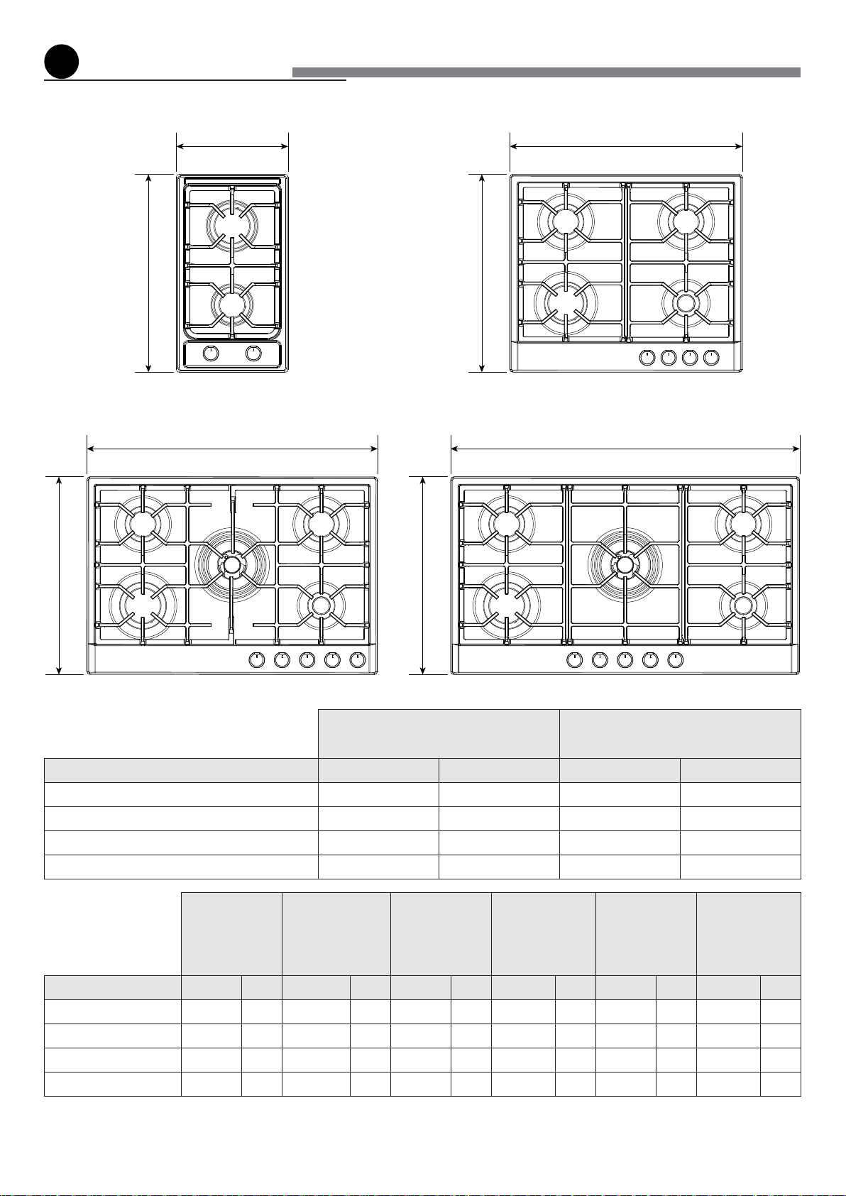
1
installationtothecabinet
Fig.1.1a Fig.1.1b
Mod. VDGCT212F..
Mod. VDGCT530FSS
Mod. VDGCT424FSS
Mod. VDGCT536FSS
Table1-COOKTOPDIMENSIONS
(Figs.1.1a,1.1b,1.1c,1.1d)
W D
MODEL Inch mm Inch mm
VDGCT212F.. 11”21/64 288 20”1/16 510
VDGCT424FSS 23”5/8 600 20”1/16 510
VDGCT530FSS 29”17/32 750 20”1/16 510
VDGCT536FSS 35”7/16 900 20”1/16 510
Table2-CUT-OUT
DIMENSIONS
(Figs.1.2a,1.2b,
1.2c,1.2d)
W1 D1
RH
(*)(**)
LH
(*)(**)
R
(*)
T
(***)
MODEL Inch mm Inch mm Inch mm Inch mm Inch mm Inch mm
VDGCT212F.. 10”5/8 270 19”9/32 490 5”63/64 152 5”63/64 152 2”11/64 55 11”13/32 290
VDGCT424FSS 22”3/64 560 18”57/64 480 7”7/8 200 11”13/16 300 2”11/64 55 23”5/8 600
VDGCT530FSS 29”9/64 735 18”57/64 480 7”7/8 200 11”13/16 300 3”5/32 80 29”17/32 750
VDGCT536FSS 33”5/64 840 18”57/64 480 7”7/8 200 11”13/16 300 3”5/32 80 35”7/16 900
(*) minimumdistancefromcut-out
(**) oneside(leftorright)abovethecounterheightmustalwaysbekeptclear
(***) minimumclearance,centredwiththecooktop
Fig.1.1c
Fig.1.1d
W
W W
W
D
D
D
D
7
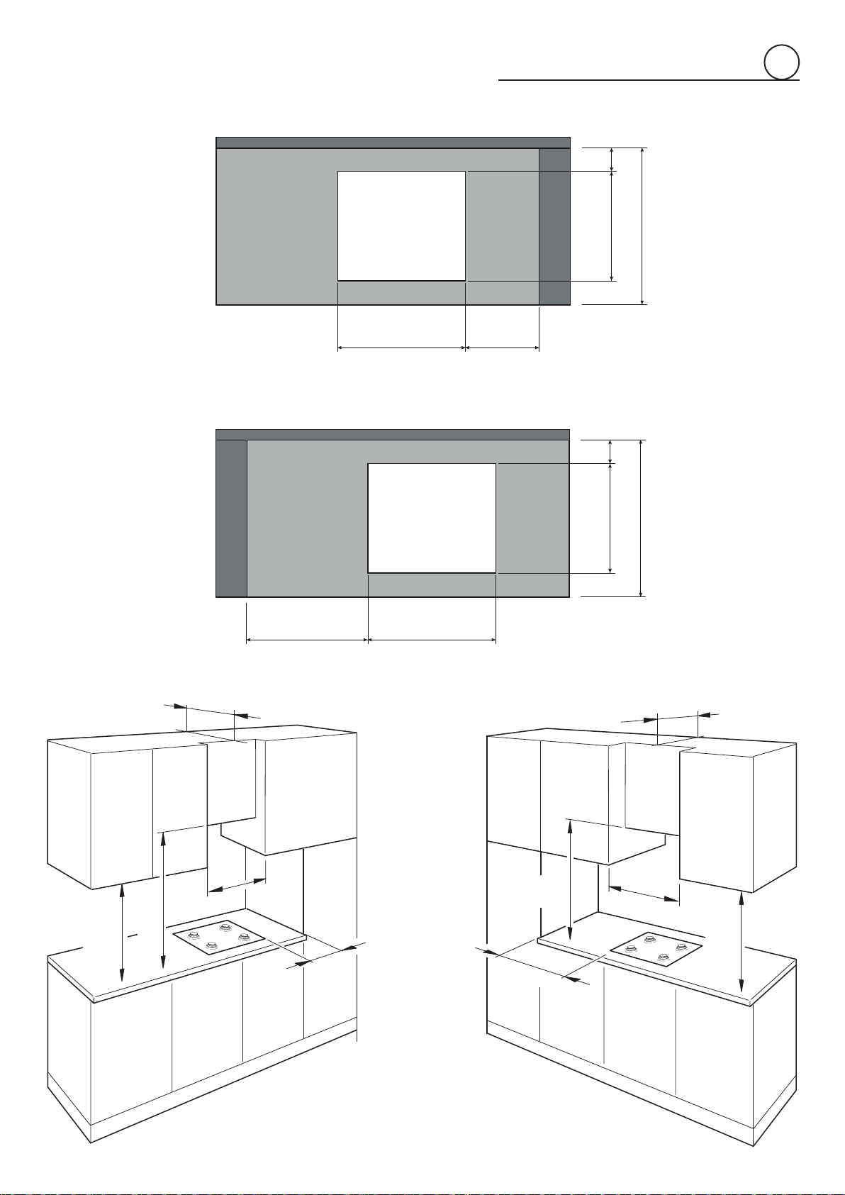
1
Fig.1.2a
Fig.1.2b
Fig.1.3a Fig.1.3b
W1 RH
LH W1
D1
24”(610mm)
24”(610mm)
max
13”
(330
mm)
RH
LH
max
13”
(330
mm)
R
RD1
18”
(457mm)
T
T
30”
(762mm)
18”
(457mm)
30”
(762mm)
8
1
PROXIMITY TO SIDE CABINETS
1. The cooktop may be installed directly to existing base
cabinets. 24” (610 mm) minimum deep countertop is
required.
Cooktop dimensions:
AsperTable1atpageno.6.
Cut-out dimensions:
AsperTable2atpageno.6.
Theremustbeaminimumclearancebetweenthebackside
ofthecut-outandthebackofthecountertopasindicatedin
theTable2atpageno.6(measure“R”).
Important:Basecabinetconstructionmustallowforsizeof
cooktopcut-out.
Gaslineopening:
Wall - anywhere 8” 1/4 (210 mm) below underside of
countertop;
Cabinetoor-anywherewithin4”17/32(115mm)ofrear
wallisrecommended.
Grounded outlet:
Theelectriccordwith3-pronggroundplughasalengthof
48”(1220 mm).Groundedoutletshouldbe locatedwithin
36”(914.4mm)ofleft-centrerearsideofcut-out.
2. The cooktop CANNOT be installed directly adjacent to
sidewalls,tallcabinets,tallappliances,orothersidevertical
surfaces.Theremustbeaminimumclearancetotheright
orto the left above thecounterheightasindicatedinthe
Table2atpageno.6(measures“RH”and“LH”).
IMPORTANT: ONE SIDE (LEFT OR RIGHT) ABOVE THE
COUNTER HEIGHT MUST ALWAYS BE KEPT CLEAR.
3. The maximum upper cabinet depth recommended is
13” (330 mm). Wall cabinet above the cooktop must be
a minimum of 30” (762 mm) above the countertop for a
minimum width as indicated in the Table 2 at page no.6
(measure“T”):ithastobecentredwiththecooktop.Side
wallcabinetsabovethecooktopmustbeaminimumof18”
(457mm)abovethecountertop.
4. If cabinet has a drawer, a 4” (102 mm) depth clearance
fromthetopofthecountertoptothetopofthedrawer(or
otherobstruction)inbasecabinetisrequired.Thedrawer
depthmay need tobe shortened toavoid interfering with
theregulator.
5. Aircurtainorotheroverheadrangehoods,whichoperate
byblowingadownwardairowontoagascooktop,shall
not be used in conjunction with gas cooktops other than
when the hood and cooktop have been designed, tested
and listed by an independent test laboratory for use in
combination.
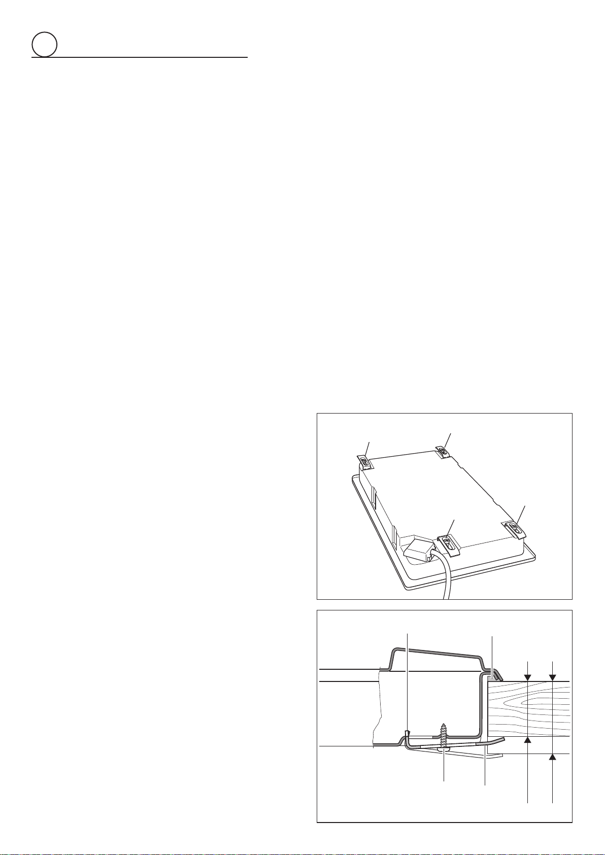
FASTENING THE COOKTOP
(Model VDGCT212F..)
Each cooktop is provided with an installation kit including
bracketsandscrewsforfasteningthecooktoptobenchesfrom
20to40mm(13/16”to1”9/16)thick,gs.1.4a,1.4b.
• CuttheunitaccordingtoTable2atpageno.6.
• Stretchgasket“D”overtheedgeoftheholemade,being
carefultooverlaythejunctionedges
• Turnthecooktopoverandputtabs“A”intothemountings,
onlytightenscrews“B”afewturns.
Make sure that the tabs are mounted correctly as shown
inthegures.Turnthetabssothatthecooktopcanbeput
intothehole.
• Putthecooktopintotheholecutintotheunitandposition
itcorrectly.
• Puttabs“A”intoplace,tooth“C”ofthetabsshouldgointo
thehole.
• Tightenscrews“B”untilthecooktopiscompletelysecured.
• Using a sharp tool cut off the part of gasket “D” which
protrudesfromthecooktop.
Takecarenottodamagethebenchtop.
A
A
A
A
20
mm min.
40
mm max.
B
D
A
C
Fig.1.4b
Fig.1.4a
20mm
(13/16”)min.
40mm
(1”9/16)max.
9
1
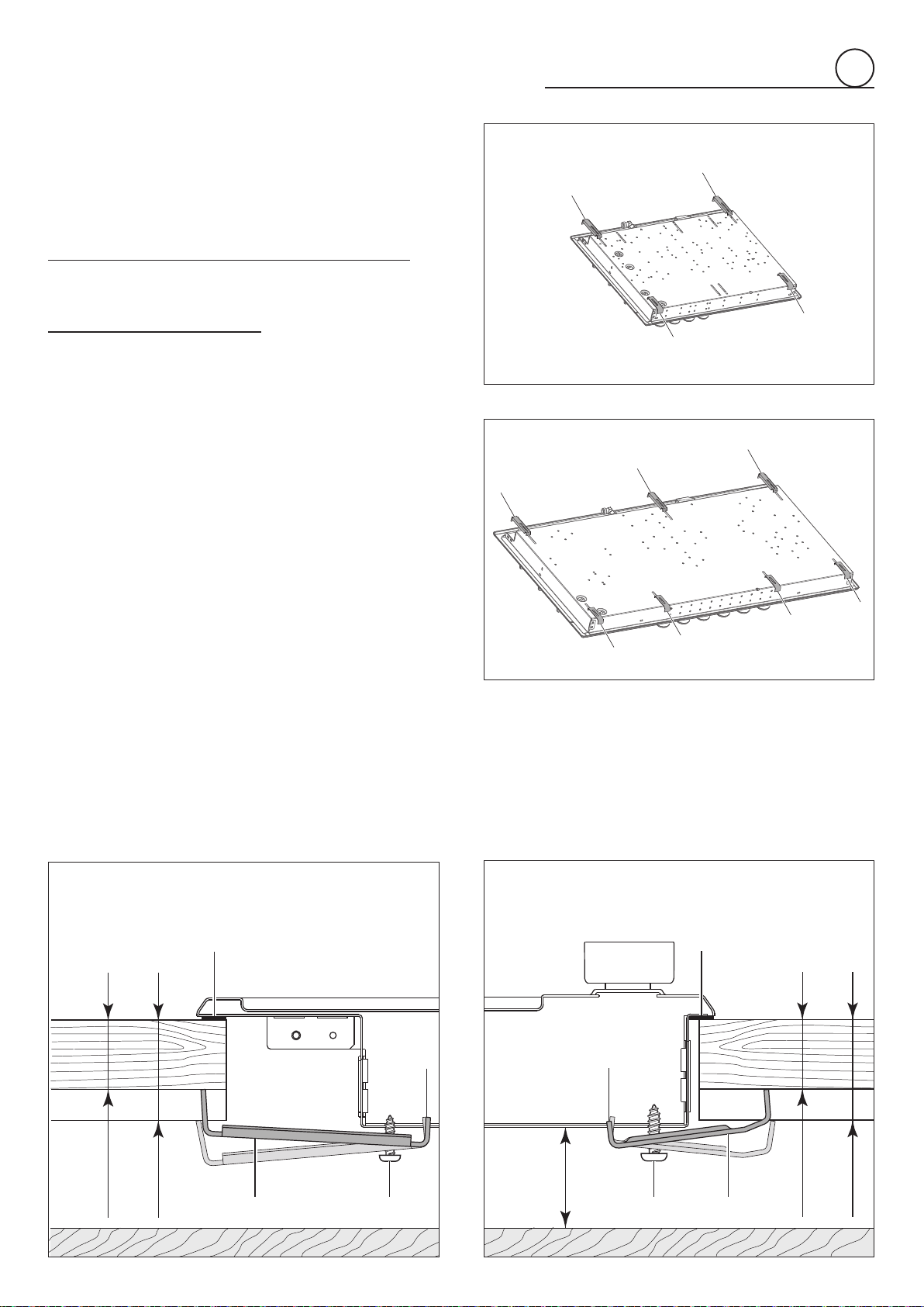
FASTENING THE COOKTOP
(Models VDGCT424FSS, VDGCT530FSS,
VDGCT536FSS)
Each cooktop is provided with an installation kit including
bracketsandscrewsforfasteningthecooktoptobenchesfrom
30to40mm(3/16”to1”9/16)thick.
Models VDGCT424FSS and VDGCT530FSS (g. 1.5a): The
kitincludestwo“F”typebrackets(forthefrontofthecooktop),
two“R”typebrackets(fortherearofthecooktop)andfourself-
threadingscrews“S”.
ModelVDGCT536FSS(g.1.5b):Thekitincludesfour“F”type
brackets(forthefrontofthecooktop),three“R”typebrackets
(for the rear of the cooktop) and seven self-threading screws
“S”.
• CuttheunitaccordingtoTable2atpageno.6.
• Stretchgasket“G”overtheedgeoftheholemade,being
carefultooverlaythejunctionedges.
• Fastenthebrackets“F”and“R”totheappropriatesocket
holes, without tightening the screws “S” for the moment.
Makesurethatthetabsaremountedcorrectly,asshownin
thegures.Rotatethetabssothatthecooktopcanbeput
intothecutout.
• Putthecooktopintothecutoutandpositionitcorrectly.
• Put the brackets “F” and “R” into place; tooth “A” of the
bracketsshouldgointothehole(gs.1.5c,1.5d).
• Tightenscrews“S”untilthecooktopiscompletelysecured
tothebench.
• Using a sharp cutter or trimmer knife, trim the excess
sealingmaterialaroundtheedgeofthecooktop.
Takecarenottodamagetheworkbench.
30 mm min.
40 mm max.
S
A
F
G
30 mm min.
40 mm max.
40 mm min.
40 mm min.
S
A
R
G
30 mm min.
40 mm max.
S
A
F
G
30 mm min.
40 mm max.
40 mm min.
40 mm min.
S
A
R
G
F
F
F
F
R
R
R
F
F
R
R
F
F
F
F
R
R
R
F
F
R
R
RearFixingBrackets
FrontFixingBrackets
Fig.1.5a
Fig.1.5b
Fig.1.5c
Fig.1.5d
30mm
(3/16”)min.
40mm
(1”9/16)max.
30mm
(3/16”)min.
40mm
(1”9/16)max.
10
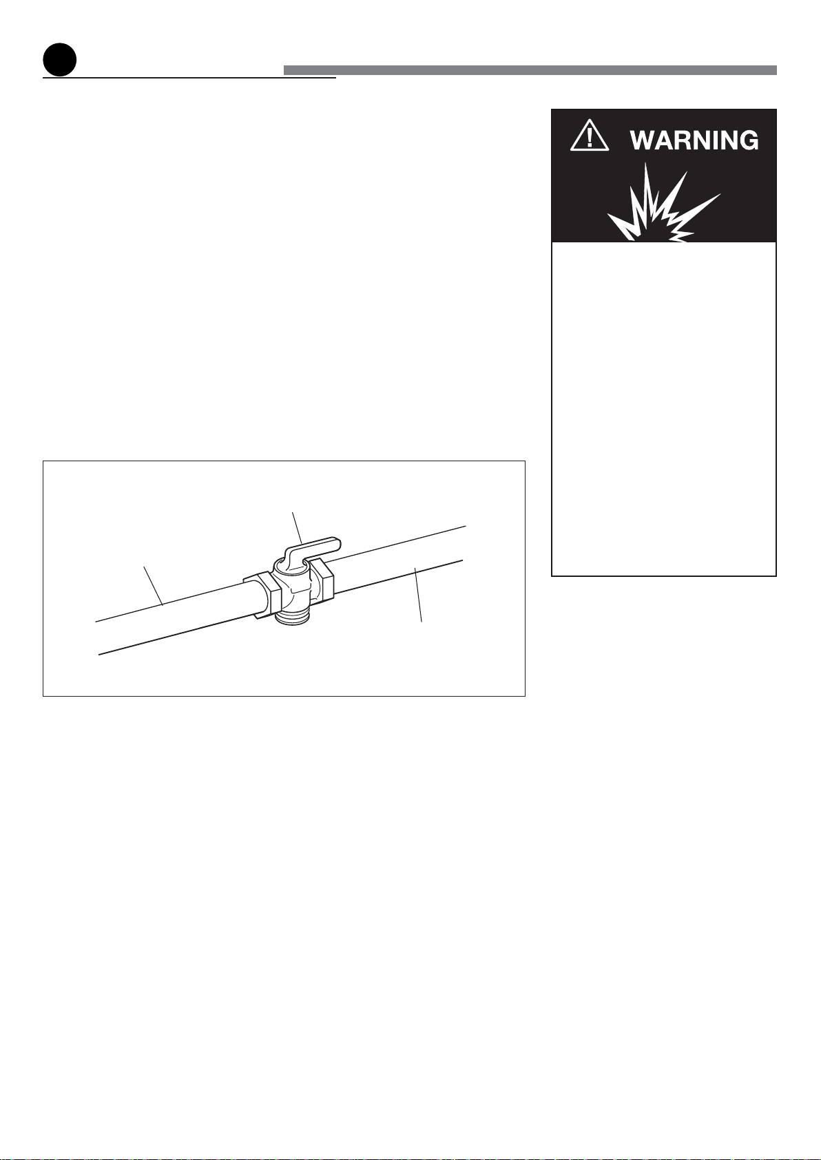
Gas supply line
Shutoff valve
“open” position
To cooktop
2
gasconnection
2.PressureRegulator:
a. Allheavyduty,commercialtypecookingequipmentmusthaveapressureregulator
ontheincomingservicelineforsafeandefcientoperation,sinceservicepressure
mayuctuatewithlocaldemand.
Beforeinstallingtheregulatormountthe3/8”NPT(conical)maleconnectortothe
regulator(seepicture2.2c).
Gasketsuppliedhastobeplacedbetween3/8”NPT(conical)connector/extension
pipemalepipefitting(seepicture2.2d).
Theregulatorsuppliedwiththiscooktopmustbeinstalledbeforeanygasconnections
aremade.
Usesuppliedpressureregulatoronly.
Explosion Hazard
Use a new CSA or UL approved
gas supply line.
Install a shut-off valve.
Securely tighten all gas connec-
tions.
If connected to LP, have a quali-
fied person make sure gas pres-
sure does not exceed 14" water
column.
Examples of a qualified person
include licensed heating per-
sonnel, authorized gas compa-
ny personnel, and authorized
service personnel.
Failure to do so can result in
death, explosion, or fire.
Fig. 2.1
Allgasconnectionsmustbemadeaccordingtonationalandlocalcodes.Thisgassupply
(service)linemustbethesamesizeorgreaterthantheinletlineoftheappliance.Sealant
onallpipejointsmustberesistanttotheactionofLP/Propanegas.
ThecooktopisequippedfortheusewithNATURALgas.Itisdesign-certiedbyCSA
InternationalforNATURALandL.P.gaseswithappropriateconversion.
Themodel/serialratingplate,locatedontheundersideoftheburnerbox,hasinformation
onthetypeofgasthatcanbeused.Ifthisinformationdoesnotagreewiththetypeof
gasavailable, check with the localgassupplier. Seepage from14 to15forL.P.gas
conversioninstructions.
1. Manual Shut-off Valve(g:2.1):
Amanualshut-offvalvemustbeinstalledinanaccessiblelocationinthegaslineexternal
tothe appliance forthe purposeof turning on orshuttingoffgas to the appliance(In
MassachusettssuchshutoffdevicesshouldbeapprovedbytheBoardofStateExaminers
ofPlumbers&GasFitters).
Thisvalveshouldbelocatedinthesameroomasthecooktopandshouldbeinalocation
thatallowseaseofopeningandclosing(inapositionwhereitcanbereachedquicklyin
theeventofanemergency).
Donotblockaccesstotheshutoffvalve.Thevalveisforturningonorshuttingoffgas
totheappliance.
11
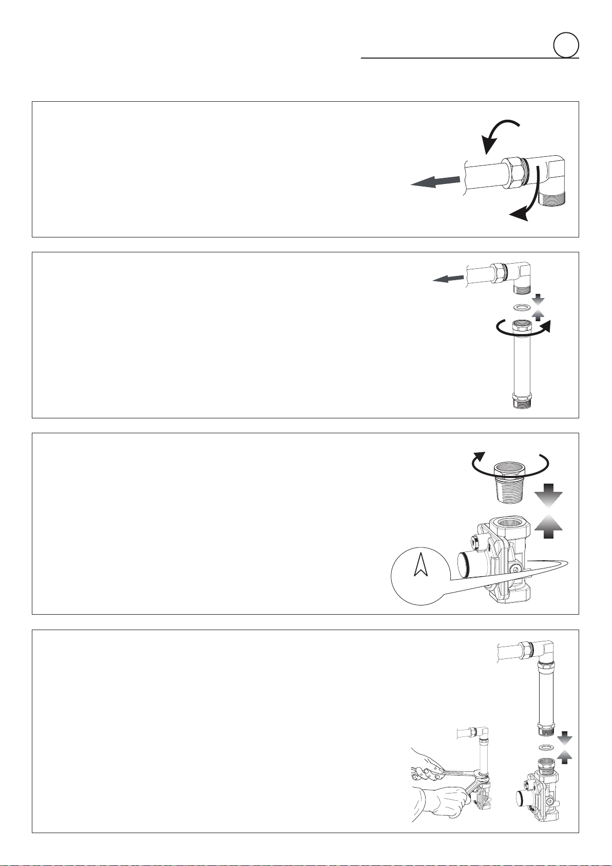
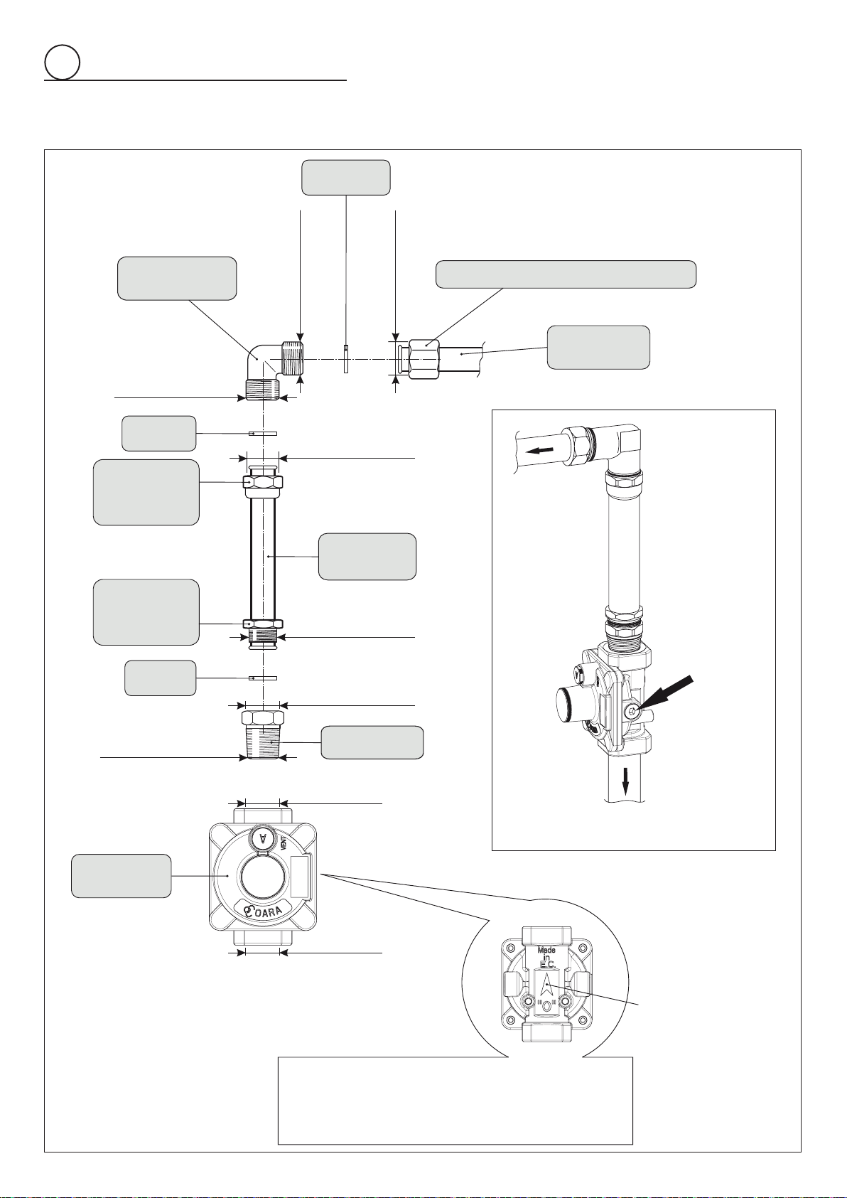
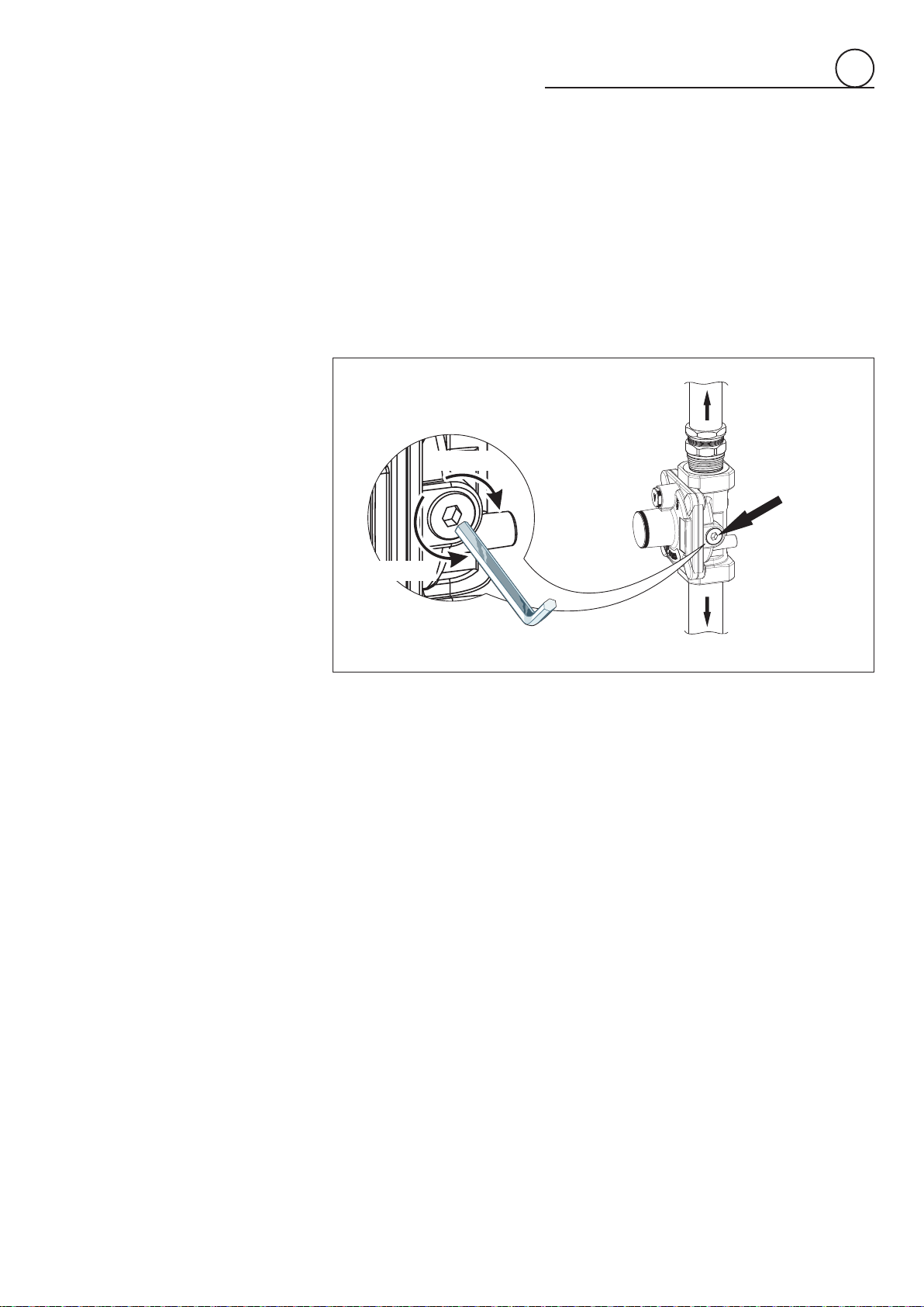
PRESSURE REGULATOR INSTALLATION
LOCK
Arrow
2
To cooktop
UNLOCK
LOCK
To cooktop
LOCK
STEP 1
Theelbowconnectioncanbeturnedinthedirectionrequiredafterthe
manifold female pipe fitting has been slackened by using a wrench.
Then tighten the elbow-manifold female pipe fitting connection by
using a wrench before proceeding with gas connection.
When tightening keep the elbow connection firm i.e. by using an
adjustable pliers or an adjustable wrench (pay attention not to
damage the thread).
STEP 2
Mount the extension pipe to the elbow connection interposing the
gasket supplied and tighten by using a wrench.
When tightening keep the elbow connection firm i.e. by using an
adjustable pliers or an adjustable wrench (pay attention not to
damage the thread).
STEP 3
Mountthe3/8”NPT(conical)maleconnectortothepressureregulator
and tighten by using a wrench.
Do not over tighten the connector.
Over tightening may crack regulator.
STEP 4
Assemblethe 3/8” NPTconnector +pressure regulator groupto the
extension pipe interposing the gasket supplied.
IMPORTANT: use two spanners to tighten the connection.
Fig. 2.2c
Fig. 2.2a
Fig. 2.2b
Fig. 2.2d
12
GAS CONNECTION SPECIFICATION
2
Gasket
Elbow
connection
Extension
pipe female
pipe tting
Extension
pipe
Extension
pipe male
pipe tting
Gasket
Gasket
Connector
Pressure
regulator
WARNING: check the right positioning
of the gas regulator. The arrow on the
back of the gas regulator must be
oriented towards the connector.
Manifold female pipe tting
Cooktop
manifold
To cooktop
Manifold
test point
pressure
1/8” NPT
Arrow
1/2” G cylindrical
(ISO 228-1) female
1/2” G cylindrical
(ISO 228-1) female
1/2” G cylindrical
(ISO 228-1) male
1/2” G cylindrical
(ISO 228-1) male
1/2” G cylindrical
(ISO 228-1) male
1/2” G cylindrical
(ISO 228-1) female
3/8” NPT
female
3/8” NPT
female
3/8” NPT (conical)
male
To mains
connection
Fig.2.3
13
b. Any conversion required must be performed by your dealer or a qualied
licensedtechnicianorgasservicecompany.Pleaseprovidetheserviceperson
withthismanualbeforeworkisstartedonthecooktop.(Gasconversionsarethe
responsibilityofthedealerorenduser.)
c. Thiscooktopcan be used withNATURALor LP/PROPANEgas. Itis shipped
fromthefactoryadjustedforusewithNATURALgas.
d. Manifoldpressureshouldbecheckedwithamanometer;NATURALgasrequires
4.0”W.C.P.andLP/PROPANErequires11.0”W.C.P.(seegurebelow).
• Incoming line pressure upstream from the regulator must be 1” W.C.P.
higherthanthemanifoldpressureinordertochecktheregulator.
• Theregulatorusedonthiscooktopcanwithstandamaximuminputpressure
of1/2PSI(14.0”W.C.P).Ifthelinepressureisinexcessofthatamount,a
step-downregulatorwillberequired.
e. The appliance, its individual shut-off valve, and pressure regulator must be
disconnectedfromthegassupplypipingsystemduringanypressuretestingof
thatsystematpressuresinexcessof1/2PSI(3.5kPa).
f. Theappliancemustbeisolatedfromthegassupplypipingsystembyclosingits
individualmanualshut-offvalveduringany pressuretestingof thegassupply
pipingsystemattestpressureequaltoorlessthan1/2PSI(3.5kPa).
3.FlexibleConnections:
Iflocalcodespermit,CSAorULdesign-certied,exiblemetalapplianceconnectoris
recommendedforconnectingthiscooktoptothegassupplyline.DoNotkinkordamage
theexibleconnectorwhenmovingthecooktop.Thepressureregulatorhas3/8”NPT
femalepipethreads.Youwillneedtodeterminethettingsrequired,dependingonthe
sizeofyourgassupplyline,exiblemetalconnectorandshutoffvalve.
4.RigidPipeConnections:
Ifrigidpipeisusedasagassupplyline,acombinationofpipettingsmustbeused
toobtainanin-lineconnectiontothecooktop.Allstrainsmustberemovedfromthe
supplyandfuellinessocooktopwillbelevelandinline.
• Use joint compounds and gaskets that are resistant to action of natural or
propanegasonallmalepipethreads.
• Do not over tighten gas tting when attaching to pressure regulator. Over
tighteningmaycrackregulator.
5.LeakTesting:
IMPORTANT:Leaktestingoftheapplianceshallbeconductedasfollows:
• After nal gas connection is made, turn on manual gas valve and test all
connectionsingassupplypipingandapplianceforgasleakswithasoapywater
solution.Duringthistestallappliancegasvalveshavetobeclosed.
• Inordertoavoidpropertydamageorseriouspersonalinjury,neveruseaIighted
match.Ifaleakispresent,tightenjointorunscrew,applymorejointcompound,
tightenagainandretestconnectionforleak.
2
To mains
connection
To oven
Manifold
test point
pressure
1/8” NPT
Screw
Unscrew
Fig.2.4
To cooktop
14
1
2
NATURAL GAS
REGULATION
LP/PROPANE
REGULATION
A
Fig.2.5
2
CONVERSION TO LP/PROPANEGAS (OR CONVERSION BACK TO THE
ORIGINAL GAS - NATURAL GAS)
Everycooktopisprovidedwithasetofinjectorsforthevarioustypesofgas.
Selecttheinjectorstobereplacedaccordingtothe“INJECTORSTABLE”.
Thenozzlediameters,expressedinhundredthsofamillimetre,aremarkedonthebodyofeachinjector.
CAUTION:Savetheoricesremovedfromtheapplianceforfutureuse.
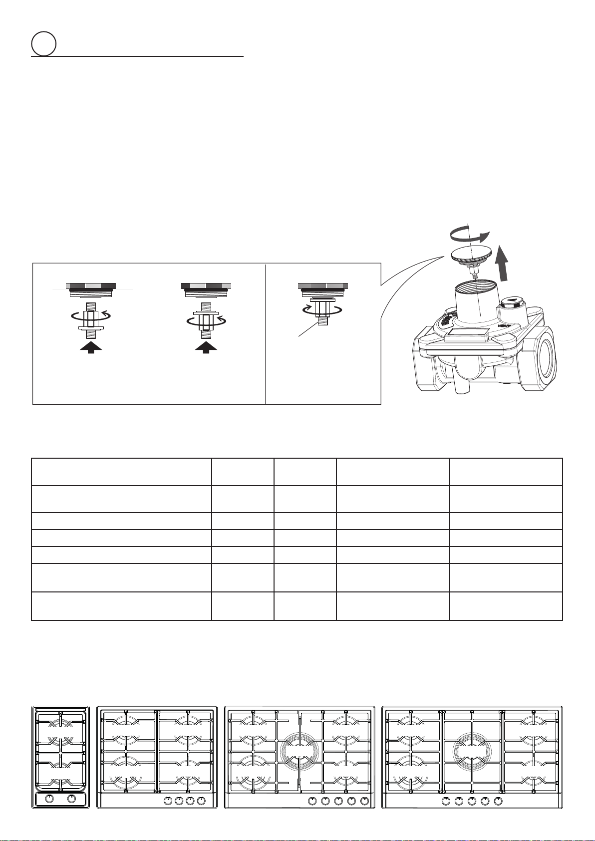
SETTING THE PRESSURE REGULATOR
1. Unscrewtheregulatorcover.
2. Unscrewthe“A”component,reverseandscrewitaccordingtotheLP/PROPANE(orNATURALGAS)
regulation.
INJECTORS TABLE
NOMINAL
POWER
REDUCED
POWER
LP/PROPANE
11”W.C.P.
NATURAL GAS
4”W.C.P.
BURNERS BTU/hr BTU/hr
Øinjector
[1/100mm]
Øinjector
[1/100mm]
Auxiliaryburner 4000 1000 58 92
Semirapidburner 7000 1500 76 123
Rapidburner 10000 2500 92 148
Dualburner(Mod.VDGCT530FSS)
16000(
1
)
15000(
2
)
5000
50(x1)(
3
)
73(x2)(
4
)
72(x1)(
3
)
135(x2)(
4
)
Dualburner(Mod.VDGCT536FSS)
18000(
1
)
16500(
2
)
5000
50(x1)(
3
)
76(x2)(
4
)
72(x1)(
3
)
143(x2)(
4
)
(
1
)PowercalculatedwithNaturalGas
(
2
)PowercalculatedwithLP/Propane
(
3
)Innercrown(“J2”ingure2.6b)
(
4
)Outercrown(“J3”ingure2.6b)
VDGCT212F..
VDGCT530FSSVDGCT424FSS VDGCT536FSS
Semirapid
Semirapid Semirapid
Semirapid
Semirapid Semirapid
Semirapid
Dual
Dual
Rapid
Rapid Rapid
Rapid
Auxiliary Auxiliary
Auxiliary
15
2
J
Auxiliary,
Semirapid
and Rapid
burner
J1
J
J
Fig. 2.6a
Fig. 2.6b
Fig. 2.7
Dualburner
Injectorfor
innercrown
Injectors
forouter
crown
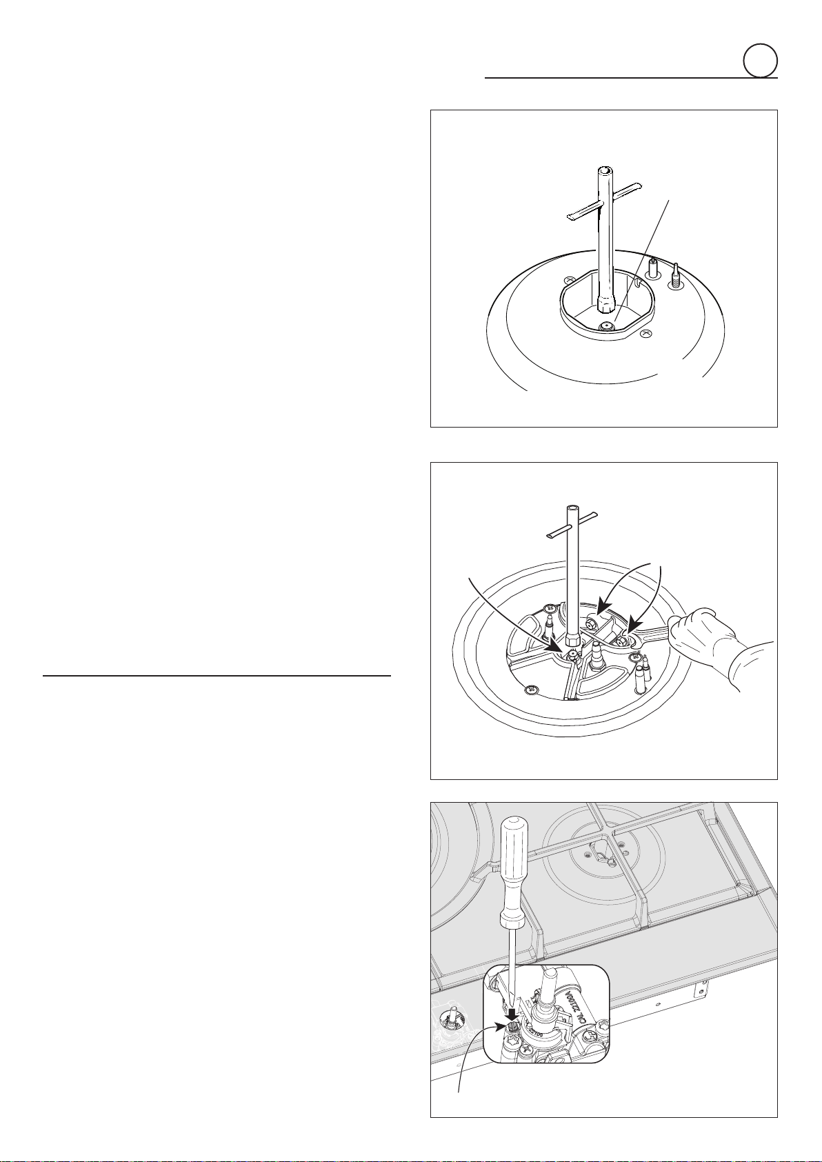
OPERATIONS TO BE PERFORMED WHEN
SUBSTITUTING THE INJECTORS
• Removethepansupports,theburnercapsandtheflame
spreaders.
• Using a wrench substitute the nozzle injectors “J1”, “J2”
and“J3”(figs.2.6a,2.6b)withthosemostsuitableforthe
kindofgasforwhichitistobeused.
• Refit the flame spreaders, the burner caps and the pan
supports.
The burners are conceived in such a way so as not to
requiretheregulationoftheprimaryair.
SETTING THE BURNER MINIMUM
Whenswitchingfromonetypeofgastoanother,theminimum
owratemustalsobecorrect:theameshouldnotgoouteven
whenpassingsuddenlyfrommaximumtominimumame.
Toregulatetheamefollowtheinstructionsbelow:
• Lighttheburner.
• Setthegasvalvetotheminimumrateposition.
• Removetheknob.
• With a thin screwdriver, turn the regulation screw “A”
(g.2.7)untiladjustmentiscorrect.
For LP/PROPANE gas, tighten the adjustment screw
completely.
A
J2
J3
After regulation repeat the operations indicated in paragraph
“2.PRESSUREREGULATOR”atpage10.
If the cooktop has been disconnected and then connected
againtothegassupplylinerepeattheoperationsindicatedin
paragraph“5.LEAKTESTING”atpage13.
IMPORTANT:
• AfterconversiontoLP/PROPANEgashasbeencarriedout
afxnearthedataplatetheconversionlabelsuppliedand
also afx a conversion label at page 3 of this instruction
manual.
• Afterconversionbacktotheoriginalgas(NATURALGAS)
has been carried out remove, near the data plate and
at page 3 of this instruction manual, the LP/PROPANE
conversionlabels.Savethelabelsremovedforfutureuse.
16
3
electrical connection
If codes permit and a separate ground wire is used, it is recommended that a
qualiedelectriciandeterminethatthegroundpathisadequate.
Check with a qualied electrician if you are not sure whether the cooktop is
properlygrounded.
DoNotgroundtoagaspipe.
A120-volt,60-Hz,AC-only,15-ampere,fusedelectricalsupplyisrequired.
Atime-delayfuseorcircuitbreakerisrecommended.
Itisrecommendedthataseparatecircuitservingonlythisappliancebeprovided.
The outlet mustbe checkedby a qualied electrician tosee if it is wiredwith correct
polarity.
Thisappliance,wheninstalled,mustbeelectricallygroundedinaccordancewithlocal
codes.
Recommendedgroundmethod
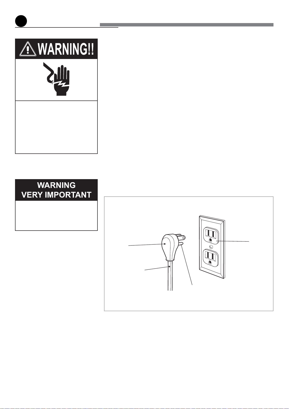
Foryourpersonalsafety,thiscooktopmustbegrounded.
Thiscooktopisequippedwitha3-pronggroundplug.
To minimize possible shock hazard, the cord must be plugged into a mating 3-prong
ground-typeoutlet,groundedinaccordancewiththeNationalElectricalCodeANSI/NFPA
70latesteditionorCanadianElectricalCode(CSA)andlocalcodesandordinances.
Ifamatingoutletisnotavailable,itisthepersonalresponsibilityandobligationofthe
customer to have a properly polarized and grounded, 3-prong outlet installed by a
qualiedelectrician.
Electrical Shock Hazard
Plug into a grounded 3-prong
outlet.
Donotremovegroundprong.
Do not use an adapter.
Failure to follow these
instructions can result in death,
re,orelectricalshock.
Before any operation of
maintenance disconnect the
appliance from the electrical main
supply.
3-prong
ground
plug
Power
supplycord
Groundprong
3-prongpolarized
ground-typeoutlet
Fig. 3.1
17
Fig. 3.2
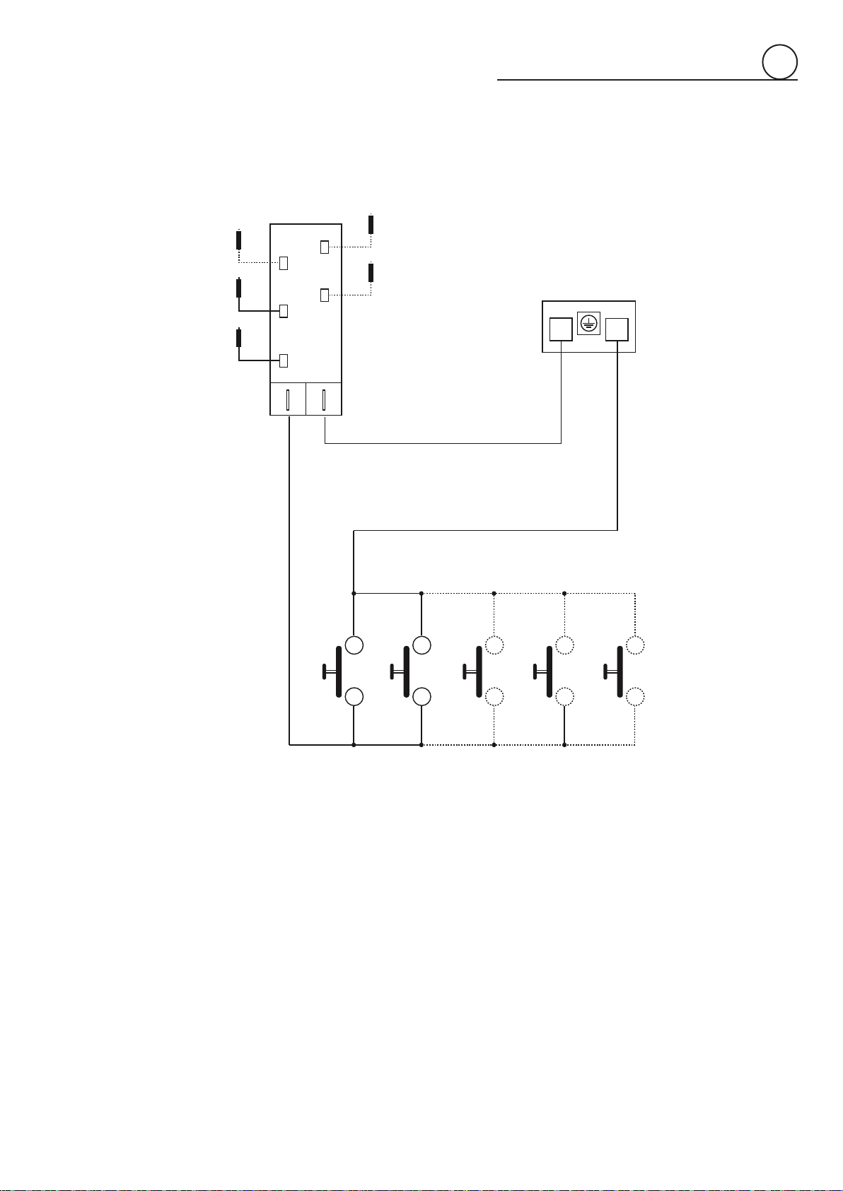
ELECTRIC DIAGRAM
3
WIRING DIAGRAM KEY
A IGNITIONCOIL
CA IGNITERS(2÷5DEPENDINGONMODEL)
PA IGNITIONSWITCHESGROUP(2÷5DEPENDINGONMODEL)
M TERMINALBLOCK
M
CA
CA
CA
CA
CA
PA
A
L
N

18

19

Cod.1106206-ß0
The manufacturer cannot be held responsible for possible inaccuracies due to
printingortranscriptionerrorsinthepresentbooklet.
Themanufacturerreservestherighttomakeallmodicationstoitsproductsdeemed
necessaryformanufactureorcommercialreasonsatanymomentandwithoutprior
notice,withoutjeopardisingtheessentialfunctionalandsafetycharacteristicsofthe
appliances.