Loading ...
Loading ...
Loading ...
,, If local codes permit, use a flexible stainless steel tubing
gas connector, design-certified and marked "outdoor" by
CSA International, to connect the side burner to the rigid
gas supply line. 5/8" diameter line is recommended. Using a
wrench to tighten, connect the gas supply to the side burner.
Use pipe joint compound on all non-flared male threads. Do
not kink or damage the flexible connector when moving the
side burner.
rear of side ,, I I
burner l/_ 1/2 side burner
-.._ g2 spipe
flexible gas _-_-_-_
connector ,_
" Pipe-joint compounds suitable for use with L.P. gas must be
used. Do not use Teflon® tape.
3. Open shutoff valve in the gas supply line. The valve is open
when the handle is parallel to the gas pipe.
valveolen
j valve closed
4. Test all connections by brushing on an approved non-
corrosive leak-detection solution. Bubbles will show a leak.
Correct any leak found.
2. Gently move Side Burner completely into enclosure.
3. Go to "Check and Adjust the Burners" section.
The burners are tested and factory-set for most efficient
operation. However, variations m gas supply and other
conditions may make minor adjustments to low flame setting
necessary. It is recommended that adjustments be made by a
qualified person.
Checking and adjusting the burner flames requires removing the
grate.
Low flame adjustment:
If flame goes out on the LO setting, the low flame setting must
be adjusted.
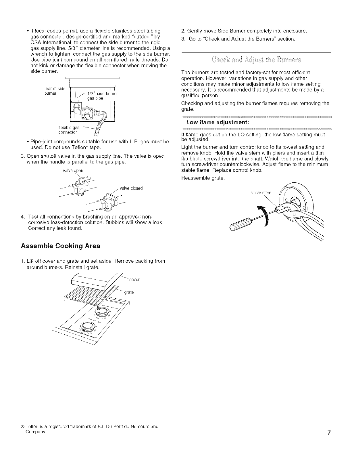
Light the burner and turn control knob to its lowest setting and
remove knob. Hold the valve stem with pliers and insert a thin
flat blade screwdriver into the shaft. Watch the flame and slowly
turn screwdriver counterclockwise. Adjust flame to the minimum
stable flame. Replace control knob.
Reassemble grate.
valve stem
Assemble Cooking Area
1. Lift off cover and grate and set aside. Remove packing from
around burners. Reinstall grate.
cover
irate
® Teflon is a registered trademark of E.I. Du Pont de Nemours and
Company. 7
Loading ...
Loading ...
Loading ...