IMPORTANT NOTE:
Read this manual carefully before installing
or operang your new air condioning
unit. Make sure to save this manual for
future reference.
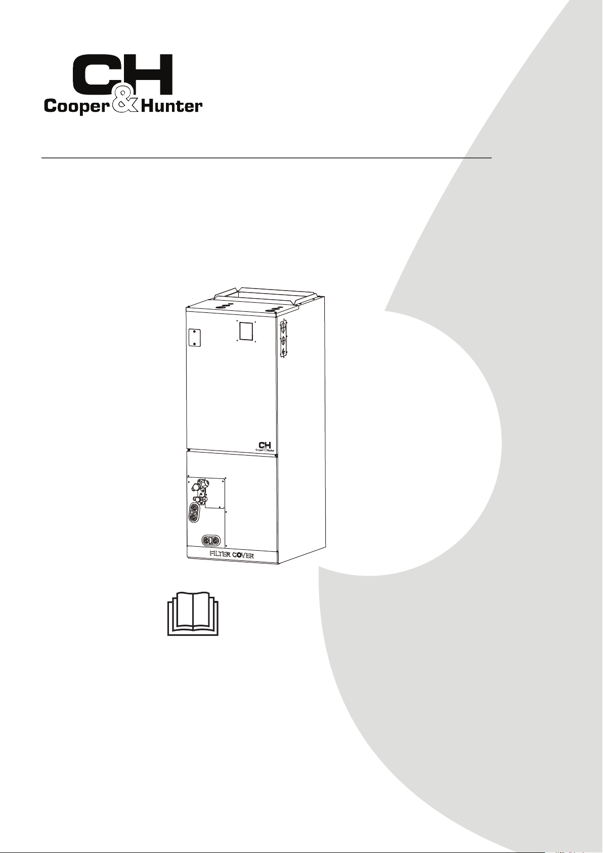
AIR-HANDLER AIR CONDITIONERS
Owner’s Manual &
Installation Manual
MODELS:
CH-36AHU
CH-48AHU
CH-60AHU

Indoor Unit Parts And Major Functions
.............................................08
Owner’s Manual
Table of Contents
Safety Precautions
............................................................................04
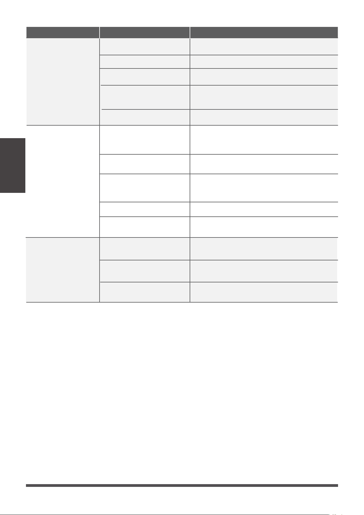
Care and Maintenance...................................................................10
Troubleshooting..............................................................................12
1. Unit Parts..............................................................................................................................................08
2. Operang Condions............................................................................................................................08
3. Features ................................................................................................................................................09
4. Energy Saving Tips.................................................................................................................................09

Installation Manual
........................................................................................15
....................................................................16
..................................................................................................................................16
...................................................................................................................................16
..........................................................................................................16
..............................................................................................................23
..................................................................28
........................................................................................................................28
.....................................................................................................................................29
..............................................................................................................................29
........................................................................31
...................................................................................................................31
.....................................................................................................................31
......................................................33
.....................................................................................................................................33
........................................................................................................33
..............................................................................................34
..............................................................................................37
..................................................................................................................................38
...................................................................................................................................39
..............................................................................................................................40
.............................................................................................................................................42
.............................................................................................................................................42
..............................................................................................................................43
..................................................................................48
.............................................................................................................................48
.......................................................................................................................49
..............................................................................................50
......................................................................................................................................50
...............................................................................................................................50
Accessories
Indoor Unit Installation
1. Indoor Unit Parts
2. Safety Precauons
3. Indoor Unit Installaon Instrucons
4. Installaon of Electric Auxiliary Heat Module
Outdoor Unit Installation
1. Select installaon locaon
2. Install drain joint
3. Anchor outdoor unit
Drainpipe Installation
1. NOTE ON PURCHASING PIPES
2. Indoor Drainpipe Installaon
Refrigerant Piping Connection
1. Safety Precauons
2. Notes On Pipe Length and Elevaon
3. Connecon Instrucons Refrigerant Piping
Wiring
1. Outdoor Uint Wiring
2. Indoor Uint Wiring
3. Specific wiring method
4. Control Logic
5. LED DISPLAY
6. DIP Switch Definions
Air Evacuation
1. Evacuaon Instrucons
2. Note on Adding Refrigerant
Test Run
1. Before Test Run
2. Test Run Instrucons
Read Safety Precautions Before Operation and Installation
The seriousness of potenal damage or injuries is classified as either a WARNING or CAUTION.
Incorrect installation due to ignoring instructions can cause serious damage or injury.
WARNING
This appliance can be used by children aged from 8 years and above and persons with reduced
This appliance is not intended for use by persons(including children) with reduced physical, sensory
or mental capabilies, or lack of experience and knowledge, unless they have been given supervision
or instrucon concerning use of the appliance by a person responsible for their safety. Children
should be supervised to ensure that they do not play with the appliance.
physical, sensory or mental capabilies or lack of experience and knowledge if they have been given
supervision or instrucon concerning use of the appliance in a safe way and understand the hazards
involved. Children shall not play with the appliance. Cleaning and user maintenance shall not be
made by children without supervision.
WARNINGS FOR PRODUCT USE
•
If an abnormal situaon arises (like a burning smell), immediately turn off the unit and disconnect
the power. Call your dealer for instrucons to avoid electric shock, fire or injury.
•
Do not
insert fingers, rods or other objects into the air inlet or outlet. This may cause injury, since
the fan may be rotang at high speeds.
•
Do not
use flammable sprays such as hair spray, lacquer or paint near the unit. This may cause
fire or combuson.
•
Do not
operate the air condioner in places near or around combusble gases. Emied gas may
collect around the unit and cause explosion.
•
Do not
•
•
Do not
expose your body directly to cool air for a prolonged period of me.
•
•
•
If the air condioner is used together with burners or other heang devices, thoroughly venlate
the room to avoid oxygen deficiency.
Safety Precautions
Do not
allow children to play with the air condioner. Children must be supervised around the
unit at all mes.
operate your air condioner in a wet room such as a bathroom or laundry room. Too
much exposure to water can cause electrical components to short circuit.
In certain funconal environments, such as kitchens, server rooms, etc., the use of specially
designed air-condioning units is highly recommended.
Improper installaon, adjustment, alteraon, service or maintenance can cause property damage,
personal injury or loss of life. Installaon and service must be performed by a licensed professional
HVAC installer or equivalent, service agency, or the gas supplier.
WARNING
This symbol indicates the possibility
of personnel injury or loss of life.
CAUTION
This symbol indicates the possibility of
property damage or serious consequences.
Safety
Precautions
Page 4
CAUTION
•
Turn off the air condioner and disconnect the power if you are not going to use it for a long me.
•
Turn off and unplug the unit during storms.
•
Make sure that water condensaon can drain unhindered from the unit.
• Do not
operate the air condioner with wet hands. This may cause electric shock.
• Do not
use device for any other purpose than its intended use.
• Do not
climb onto or place objects on top of the outdoor unit.
•
•
Do not
allow the air condioner to operate for long periods of me with doors or windows open,
or if the humidity is very high.
ELECTRICAL WARNINGS
•
Only use the specified power cord. If the power cord is damaged, it must be replaced by the
manufacturer
, its service agent or similarly qualified persons in order to avoid a hazard.
•
Keep power plug clean. Remove any dust or grime that accumulates on or around the plug. Dirty
plugs can cause fire or electric shock.
•
•
•
•
•
•
•
Do not
pull power cord to unplug unit. Hold the plug firmly and pull it from the outlet. Pulling
directly on the cord can damage it, which can lead to fire or electric shock.
Do not
modify the length of the power supply cord or use an extension cord to power the unit.
Do not
share the electrical outlet with other appliances. Improper or insufficient power supply
can cause fire or electrical shock.
If connecng power to fixed wiring, an all-pole disconnecon device which has at least 3mm
clearances in all poles, and have a leakage current that may exceed 10mA, the residual current
device(RCD) having a rated residual operang current not exceeding 30mA, and disconnecon
must be incorporated in the fixed wiring in accordance with the wiring rules.
For all electrical work, follow all local and naonal wiring standards, regulaons, and the
Installaon Manual. Connect cables ghtly, and clamp them securely to prevent external forces
from damaging the terminal. Improper electrical connecons can overheat and cause fire, and may
also cause shock.
All electrical connecons must be made according to the Electrical Connecon
Diagram located on the panels of the indoor and outdoor units.
All wiring must be properly arranged to ensure that the control board cover can close properly. If
the control board cover is not closed properly, it can lead to corrosion and cause the connecon
points on the terminal to heat up, catch fire, or cause electrical shock.
The product must be properly grounded at the me of installaon, or electrical shock may occur.
TAKE NOTE OF FUSE SPECIFICATIONS
The air condioner’s circuit board (PCB) is designed with a fuse to provide overcurrent protecon.
The specificaons of the fuse are printed on the circuit board ,examples of such are T5A/250VAC and
T10A/250VAC.
As with any mechanical equipment, contact with sharp sheet metal edges can result in personal
injury. Take care while handling this equipment and wear gloves and protecve clothing.
Safety
Precautions
Page 5
•
Do not
clean the air condioner with combusble cleaning agents. Combusble cleaning agents
can cause fire or deformaon.
CLEANING AND MAINTENANCE WARNINGS
•
Turn off the device and disconnect the power before cleaning. Failure to do so can cause electrical
shock.
•
Do not
clean the air condioner with excessive amounts of water.

Note
MODEL
PRESSURE
The allowed static pressure range of the
air condioner
on site is 0-200Pa.
Test static pressure
12-24K
25Pa 37Pa
50Pa
30-36K 48-60K
Safety
Precautions
Page 6
WARNINGS FOR PRODUCT INSTALLATION
1.
Installaon must be performed by an authorized dealer or specialist. Defecve installaon can
Excessive Weight Hazard - Use two or more people when moving and installing the unit. Failure
to do so can result in back or other type of injury.
cause water leakage, electrical shock, or fire.
2.
Installaon must be performed according to the installaon instrucons. Improper installaon
can cause water leakage, electrical shock, or fire.
(In North America,installaon must be performed in accordance with the requirement of NEC
and CEC by authorized personnel only.)
3.
Contact an authorized service technician for repair or maintenance of this unit. This appliance
shall be installed in accordance with naonal wiring regulaons.
4.
Only use the included accessories, parts, and specified parts for installaon. Using non-standard
parts can cause water leakage, electrical shock, fire, and can cause the unit to fail.
5.
6.
Install the unit in a firm locaon that can support the unit’s weight. If the chosen locaon cannot
support the unit’s weight, or the installaon is not done properly, the unit may drop and cause
serious injury and damage.
7.
8.
9.
10.
11.
12.
Do not turn on the power unl all work has been completed.
When moving or relocang the air condioner, consult experienced service technicians for
disconnecon and reinstallaon of the unit.
How to install the appliance to its support, please read the informaon for details in "indoor unit
installaon" and "outdoor unit installaon" secons .
For units that have an auxiliary electric heater, do not install the unit within 1 meter (3 feet) of
any combusble materials.
Do not
install the unit in a locaon that may be exposed to combusble gas leaks. If combusble
gas accumulates around the unit, it may cause fire.
Install drainage piping according to the instrucons in this manual. Improper drainage may
cause water damage to your home and property.
Note about Fluorinated Gasses(Not applicable to the unit using R290 Refrigerant)
1.
This air-condioning unit contains fluorinated greenhouse gasses. For specific informaon on the
type of gas and the amount, please refer to the relevant label on the unit itself or
the
“Owner's Manual - Product Fiche ” in the packaging of the outdoor unit.
(European Union
products only)
.
2.
Installaon, service, maintenance and repair of this unit must be performed by a cerfied
technician.
3.
Product uninstallaon and recycling must be performed by a cerfied technician.
4.
For equipment that contains fluorinated greenhouse gases in quanes of 5 tonnes of CO
2
equivalent or more, but of less than 50 tonnes of CO
2
equivalent, If the system has a leak-
detecon system installed, it must be checked for leaks at least every 24 months.
5.
When the unit is checked for leaks, proper record-keeping of all checks is strongly recommended.
Disposal Guidelines
This appliance contains refrigerant and other potenally hazardous materials. When disposing of
this appliance, the law requires special collecon and treatment. Do not dispose of this product as
household waste or unsorted municipal waste.
When disposing of this appliance, you have the following opons:
• Dispose
of
the
appliance
at
designated
municipal
electronic
waste
collecon
facility.
• When buying a new appliance, the retailer will take back the old appliance free of charge.
• The manufacturer will take back the old appliance free of charge.
• Sell the appliance to cerfied scrap metal dealers.
Special notice
Disposing of this appliance in the forest or other natural surroundings endangers your health and is bad
for the environment. Hazardous substances may leak into the ground water and enter the food chain.
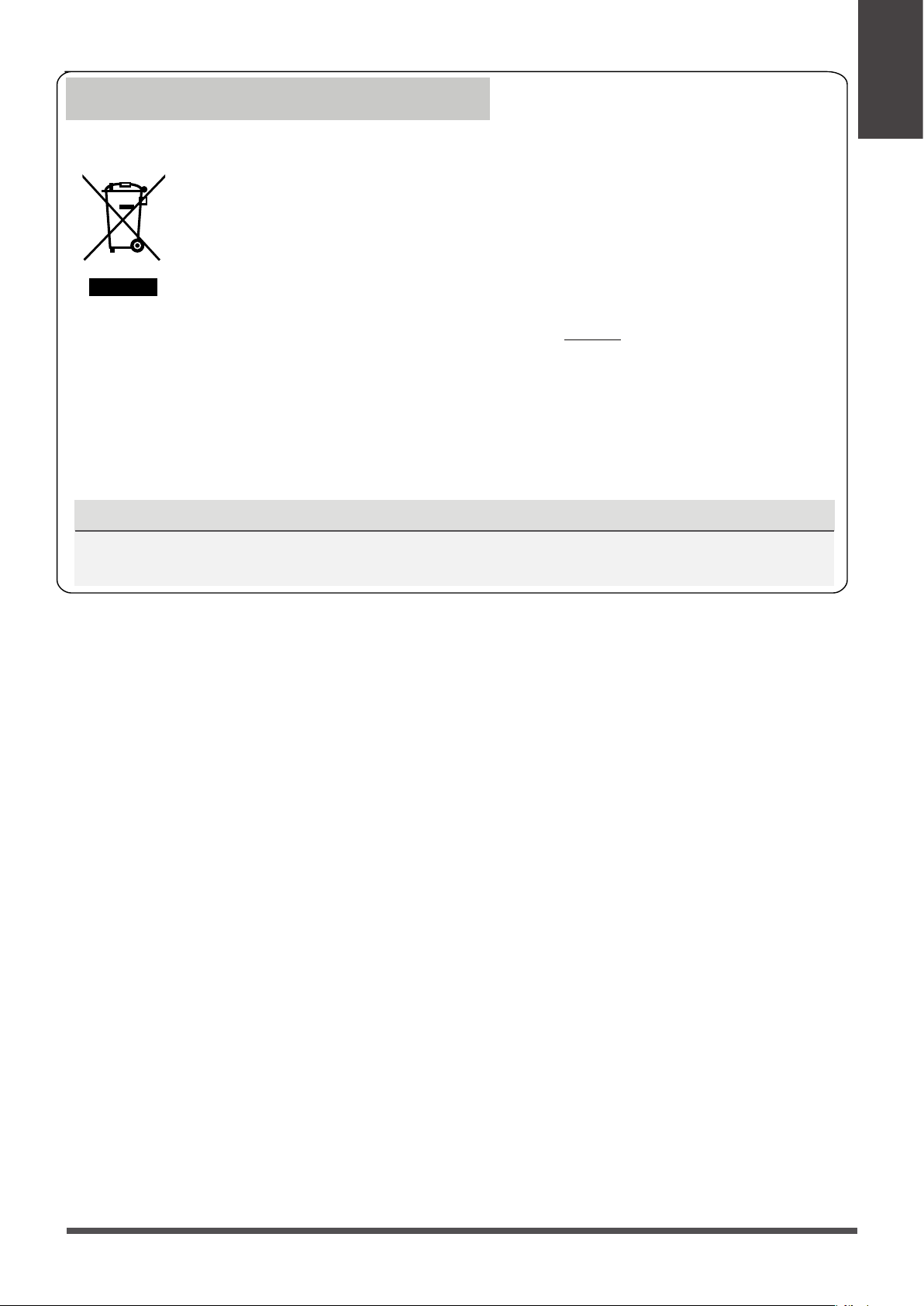
Correct Disposal of This Product
(Waste Electrical & Electronic Equipment)
This marking shown on the product or its literature, indicates that waste electrical and
eletrical equipment should not be mixed with general household waste.
Safety
Precautions
Page 7
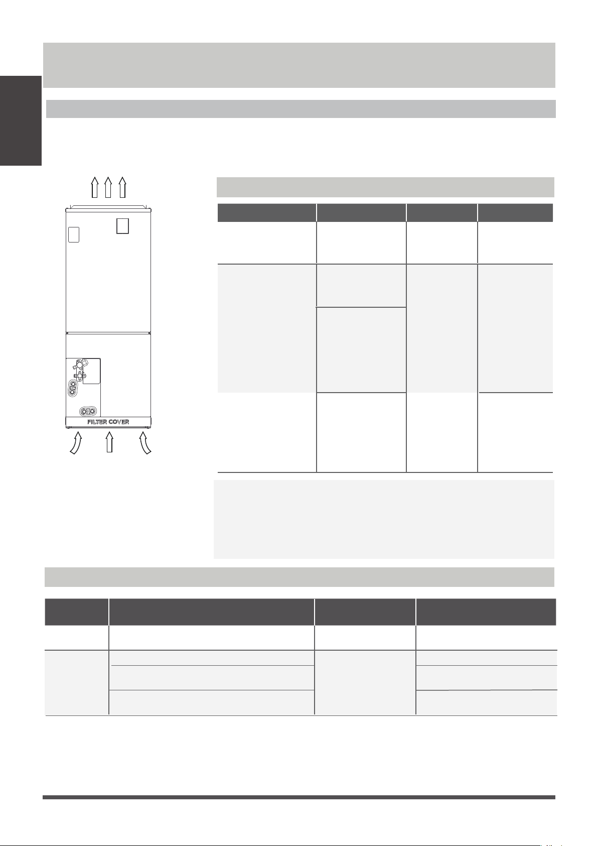
NOTE: Room relave humidity less than 80%. If the air condioner operates in excess of this
figure, the surface of the air condioner may aract condensaon. Please sets the vercal air
flow louver to its maximum angle (vercally to the floor), and set HIGH fan mode.
Room
Temperature
62°F-90°F(17°C-32°C )
32°F-86°F
(0°C-30°C)
50°F-90°F (10°C-32°C)
Outdoor
Temperature
64°F-109°F (18°C-43°C)
19°F-75°F
(-7°C-24°C )
52°F-109°F (11°C-43°C)
19°F-109°F (-7°C-43°C)
(For models with low-temp cooling systems)
64°F-109°F (18°C-43°C)
64°F-126°F (18°C-52°C)
(For special tropical models)
64°F-126°F (18°C-52°C)
(For special tropical models)
COOL mode
HEAT mode
DRY mode
COOL mode HEAT mode DRY mode
Room Temperature
(17°C - 32°C)
62°F - 90°F
32°F - 86°F
(0°C - 30°C)
50°F - 90°F
(10°C - 32°C)
Outdoor
Temperature
32°F - 122°F
(0°C - 50°C)
5°F - 75°F
(-15°C - 24°C)
32°F - 122°F
(0°C - 50°C)
32°F - 126°F
(0°C - 52°C)
(For special
tropical models)
32°F - 126°F
(0°C - 52°C)
(For special
tropical models)
5°F - 122°F
(-15°C - 50°C)
(For models with
low temp. cooling
systems.)
Indoor Unit Parts And Major Functions
Unit Parts
Operating Conditions
Use the system under the following temperatures for safe and
effecve operaon. If the air condioner is used under different
condions, it may malfuncon or become less efficient.
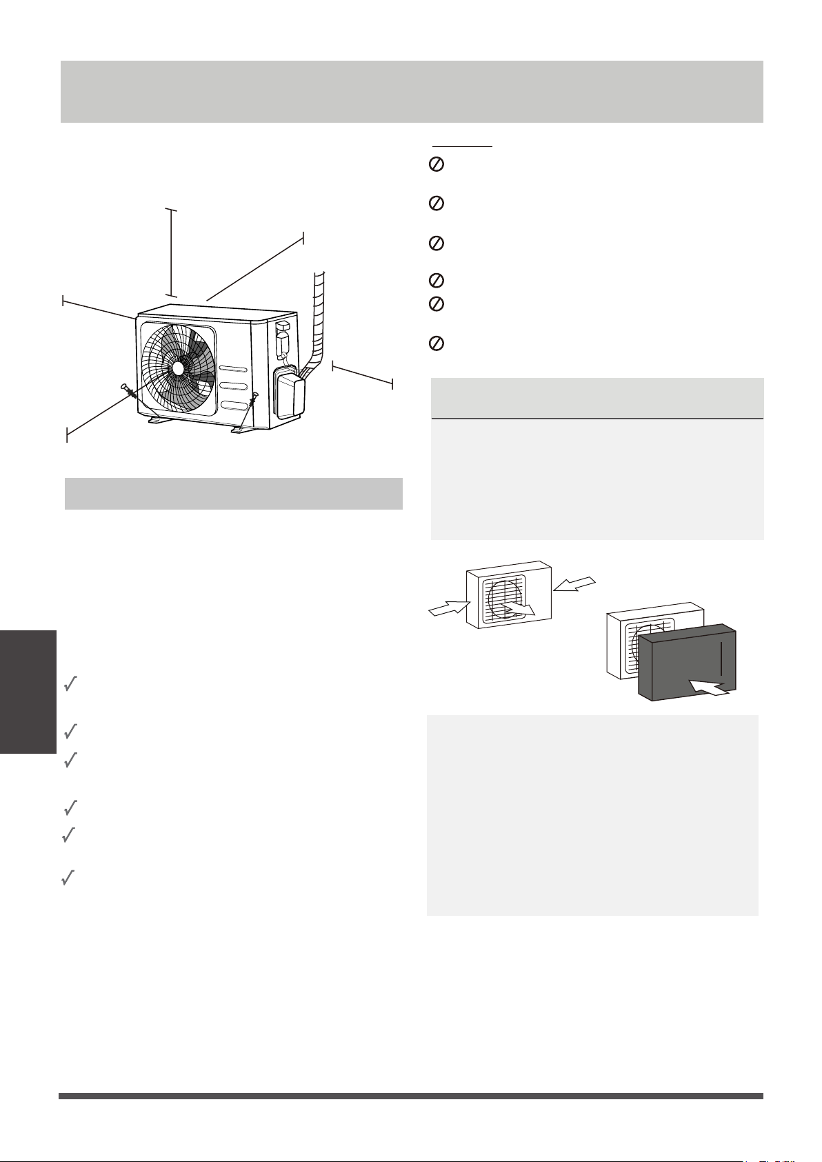
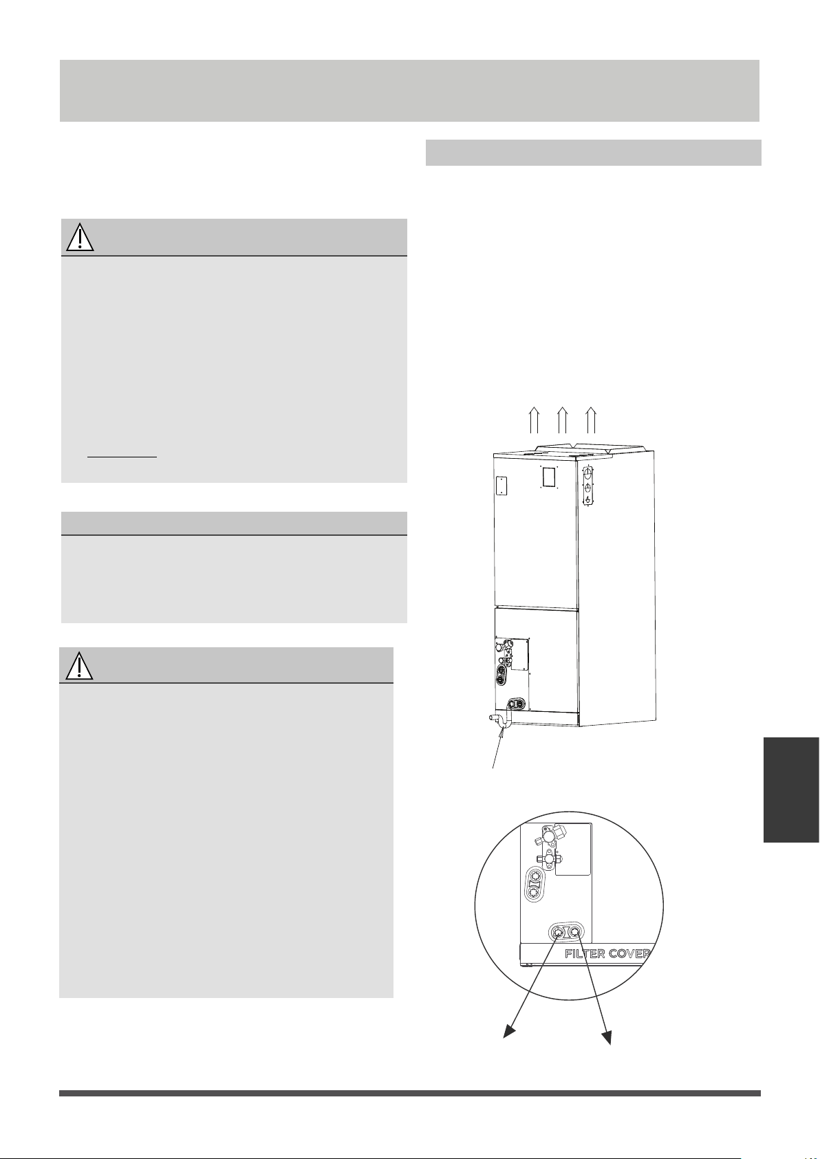
Air outlet
Air inlet
FOR OUTDOOR UNITS WITH AUXILIARY ELECTRIC HEATER
Inverter Split Type
When outside temperature is below 32°F(0°C), we strongly
recommend keeping the unit plugged in at all me to ensure
smooth on going performance.
Fixed-speed Type
Indoor Unit
Parts And
Major Functions
Page 8
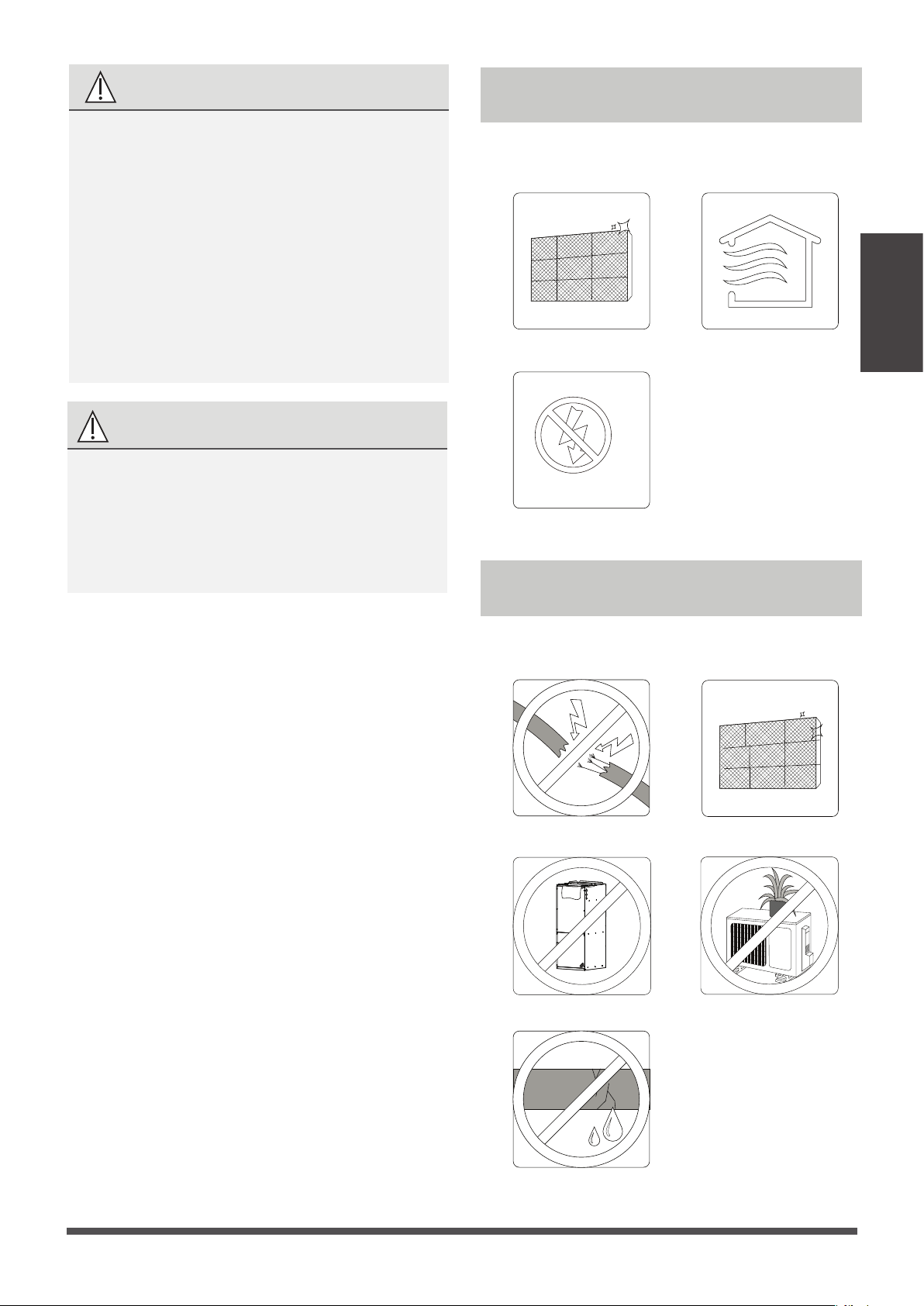
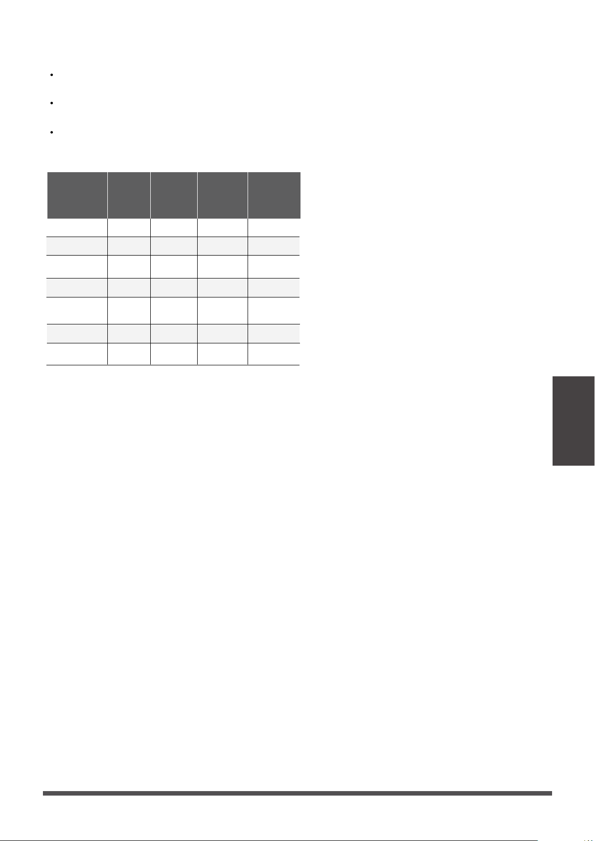
To further optimize the performance of your unit, do the following:
• Keep doors and windows closed.
• Limit energy usage by using TIMER ON and TIMER OFF funcons.
• Do not block air inlets or outlets.
• Regularly inspect and clean air filters.
Energy Saving Tips
•
DO NOT
set the unit to excessive temperature levels.
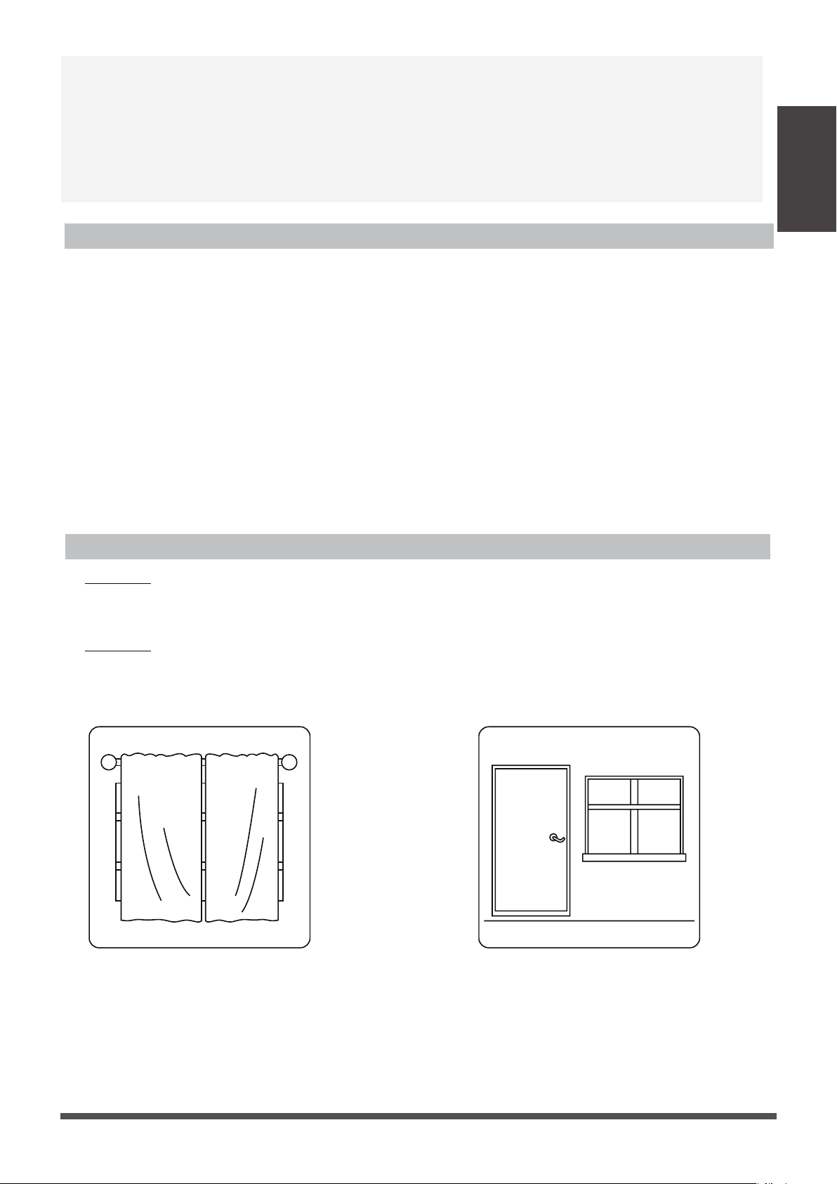
• While cooling, close the curtains to avoid direct sunlight.
• Doors and windows should be kept closed to keep cool or warm air in the room.
•
DO NOT
place objects near the air inlet and outlet of the unit.
• Clean the air filter every two weeks.
• Adjust louvers properly and avoid direct airflow.
Features
Refrigerant Leak Detection System
(some models)
In the event of a refrigerant leak, the LCD screen
will display “EL0C” and the LED indicator light will
flash.
Closing curtains during heating also
helps keep the heat in
Doors and windows should be kept
closed
Indoor Unit
Parts And
Major Functions
NOTE:
1. Under normal working condions, the switch,
wind speed and temperature can not be adjusted
by remote control.
2. Requirements of wire controller:
Control AXU funcon for live heang
The default temperature of the first power-on is
set to 16 degrees for refrigeraon and 30 degrees
for heang. When the temperature stops, the
temperature is set at the room temperature at that
me.
Page 9

Care and Maintenance
If using a vacuum cleaner,
the inlet side should face
the vacuum.
If using water, the inlet side
should face down and away
from the water stream.
Air filter
cover plate
Air filter
Care and
Maintenance
Page 10
BEFORE CLEANING OR
MAINTENANCE
ALWAYS TURN OFF YOUR AIR CONDITIONER
SYSTEM AND DISCONNECT ITS POWER SUPPLY
BEFORE CLEANING OR MAINTENANCE.
CAUTION
Only use a so, dry cloth to wipe the unit clean.
If the unit is especially dirty, you can use a cloth
soaked in warm water to wipe it clean.
•
Do not use chemicals or chemically treated
cloths to clean the unit
•
Do not use benzene, paint thinner, polishing
powder or other solvents to clean the unit.
They can cause the plasc surface to crack
or deform.
•
•
Do not use water hoer than 104°F (40°C)
to clean the front panel. This can cause the
panel to deform or become discolored.
DO NOT
wash the unit under running water.
Doing so creates an electrical hazard.
Clean the unit using a damp, lint-free cloth
and neutral detergent. Dry the unit with a
dry, lint-free cloth.
• Contact an authorized service technician for
repair or maintenance. Improper repair and
maintenance may cause water leakage,
electrical shock, or fire, and may void your
warranty.
• DO NOT
substute a blown fuse with a
higher or lower amperage rang fuse, as this
may cause circuit damage or an electrical fire.
• Make sure the drain hose is set up according
to the instrucons. Failure to do so could
cause leakage and result in personal property
damage, fire and electric shock.
• Make sure that all wires are connected
properly. Failure to connect wires according
to instrucons can result in electrical shock
or fire.
Cleaning Your Indoor Unit
2. Remove the air filter.
3. Clean the air filter by vacuuming the surface or
washing it in warm water with mild detergent.
1. Remove filter cover plate.
How To Clean The Air Filter
The filter prevents dust and other parcles from
entering the indoor unit. Dust buildup can reduce
the efficiency of the air condioner. For opmum
efficiency, clean the air filter every two weeks or
more frequently if you live in a dusty area.
Replace the filter with a new one if it’s heavily
clogged and cannot be cleaned.
NOTE: In households with animals, you will have
to periodically wipe down the grille to prevent
animal hair blocking airflow.
This product filter is only used for energy efficiency
sampling test
, the user needs to use a filter that
meets the requirements of UL900.
WARNING: DO NOT REMOVE OR
CLEAN THE FILTER BY YOURSELF
Removing and cleaning the filter can be dangerous.
Removal and maintenance must be performed by
a cerfied technician.
Maintenance –
Long Periods of Non-Use
If you plan not to use your air condioner for an
extended period of me, do the following:
Clean all filters
Turn on FAN funcon unl
unit dries out completely
Turn off the unit and
disconnect the power
Maintenance –
Pre-Season Inspection
Aer long periods of non-use, or before periods
of frequent use, do the following:
Check for damaged wires Clean all filters
Check for leaks
Make sure nothing is blocking all air inlets and outlets
CAUTION
•
Before changing the filter or cleaning,
turn off the unit and disconnect its power
supply.
•
When removing filter, do not touch metal
parts in the unit. The sharp metal edges can
cut you.
•
Do not use water to clean the inside of the
indoor unit. This can destroy insulaon and
cause electrical shock.
•
Do not expose filter to direct sunlight when
drying. This can shrink the filter.
CAUTION
•
Any maintenance and cleaning of outdoor
unit should be performed by an authorized
dealer or a licensed service provider.
•
Any unit repairs should be performed by an
authorized dealer or a licensed service provider.
Care and
Maintenance
Page 11
Common Issues
The following problems are not a malfuncon and in most situaons will not require repairs.
Issue Possible Causes
Unit does not turn
on when pressing
ON/OFF button
The Unit has a 3-minute protecon feature that prevents the unit from overloading.
The unit cannot be restarted within three minutes of being turned off.
The unit may change its seng to prevent frost from forming on the unit.
Once the temperature increases, the unit will start operang in the previously
selected mode again.
The set temperature has been reached, at which point the unit turns off the
compressor. The unit will connue operang when the temperature fluctuates
again.
The indoor unit
emits white mist
In humid regions, a large temperature difference between the room’s air and the
condioned air can cause white mist.
Both the indoor and
outdoor units emit
white mist
When the unit restarts in HEAT mode aer defrosng, white mist may be emied
due to moisture generated from the defrosng process.
Troubleshooting
The unit changes from
COOL/HEAT mode to
FAN mode
The indoor unit makes
noises
A squeaking sound may occur aer running the unit in HEAT mode due to expansion
and contracon of the unit’s plasc parts.
Both the indoor unit
and outdoor unit make
noises
Low hissing sound during operaon: This is normal and is caused by refrigerant gas
flowing through both indoor and outdoor units.
Low hissing sound when the system starts, has just stopped running, or is defrosng:
This noise is normal and is caused by the refrigerant gas stopping or changing direcon.
Squeaking sound: Normal expansion and contracon of plasc and metal parts
caused by temperature changes during operaon can cause squeaking noises.
SAFETY PRECAUTIONS
If any of the following condions occurs, turn off your unit immediately!
• The power cord is damaged or abnormally warm
• You smell a burning odor
• The unit emits loud or abnormal sounds
• A power fuse blows or the circuit breaker frequently trips
• Water or other objects fall into or out of the unit
DO NOT ATTEMPT TO FIX THESE YOURSELF! CONTACT AN AUTHORIZED
SERVICE PROVIDER IMMEDIATELY!
Cooling and Heang Models: If the Operaon light and PRE-DEF (Pre-heang/
Defrost) indicators are lit up, the outdoor temperature is too cold and the unit’s
an-cold wind is acvated in order to defrost the unit.
In Cooling-only Models: If the “Fan Only” indicator is lit up, the outdoor
temperature is too cold and the unit’s an-freeze protecon is acvated in order
to defrost the unit.
A squeaking sound is heard when the system is OFF or in COOL mode. The noise is
also heard when the drain pump (oponal) is in operaon.
Troubleshooting
Page 12
Troubleshooting
Issue Possible Causes
The outdoor unit
makes noises
The unit will make different sounds based on its current operang mode.
Dust is emitted from
either the indoor or
outdoor unit
The unit may accumulate dust during extended periods of non-use, which will be emied
when the unit is turned on. This can be migated by covering the unit during long periods
of inacvity.
The unit emits a
bad odor
The unit may absorb odors from the environment (such as furniture, cooking, cigarees,
etc.) which will be emied during operaons.
The unit’s filters have become moldy and should be cleaned.
The fan of the outdoor
unit does not operate
During operaon, the fan speed is controlled to opmize product operaon.
NOTE:
If problem persists, contact a local dealer or your nearest customer service center. Provide
them with a detailed descripon of the unit malfuncon as well as your model number.
Troubleshooting
When troubles occur, please check the following points before contacng a repair company.
Problem Possible Causes Solution
Poor Cooling
Performance
Temperature seng may be higher
than ambient room temperature
Lower the temperature seng
The heat exchanger on the indoor
or outdoor unit is dirty
Clean the affected heat exchanger
The air filter is dirty
Remove the filter and clean it according to
instrucons
The air inlet or outlet of either
unit is blocked
Turn the unit off, remove the obstrucon
and turn it back on
Doors and windows are open
Make sure that all doors and windows are
closed while operang the unit
Excessive heat is generated
by sunlight
Close windows and curtains during periods
of high heat or bright sunshine
Too many sources of heat in the
room (people, computers,
electronics, etc.)
Reduce amount of heat sources
Low refrigerant due to leak
or long-term use
Check for leaks, re-seal if necessary and
top off refrigerant
Page 13
Troubleshooting
Problem Possible Causes Solution
The unit is not
working
Power failure
Wait for the power to be restored
The power is turned off Turn on the power
The fuse is burned out
Replace the fuse
The Unit’s 3-minute protecon
has been acvated
Wait three minutes aer restarng
the unit
Timer is acvated
Turn mer off
The unit starts and
stops frequently
There’s too much or too lile
refrigerant in the system
Check for leaks and recharge the
system with refrigerant.
Incompressible gas or moisture
has entered the system.
Evacuate and recharge the system
with refrigerant
The compressor is broken Replace the compressor
The voltage is too high or
too low
Install a manostat to regulate the
voltage
Poor heating
performance
The outdoor temperature is
extremely low
Use auxiliary heang device
Cold air is entering through
doors and windows
Make sure that all doors and
windows are closed during use
Low refrigerant due to leak or
long-term use
Check for leaks, re-seal if necessary
and top off refrigerant
System circuit is blocked
Determine which circuit is blocked and
replace the malfunconing piece of
equipment
Page 14
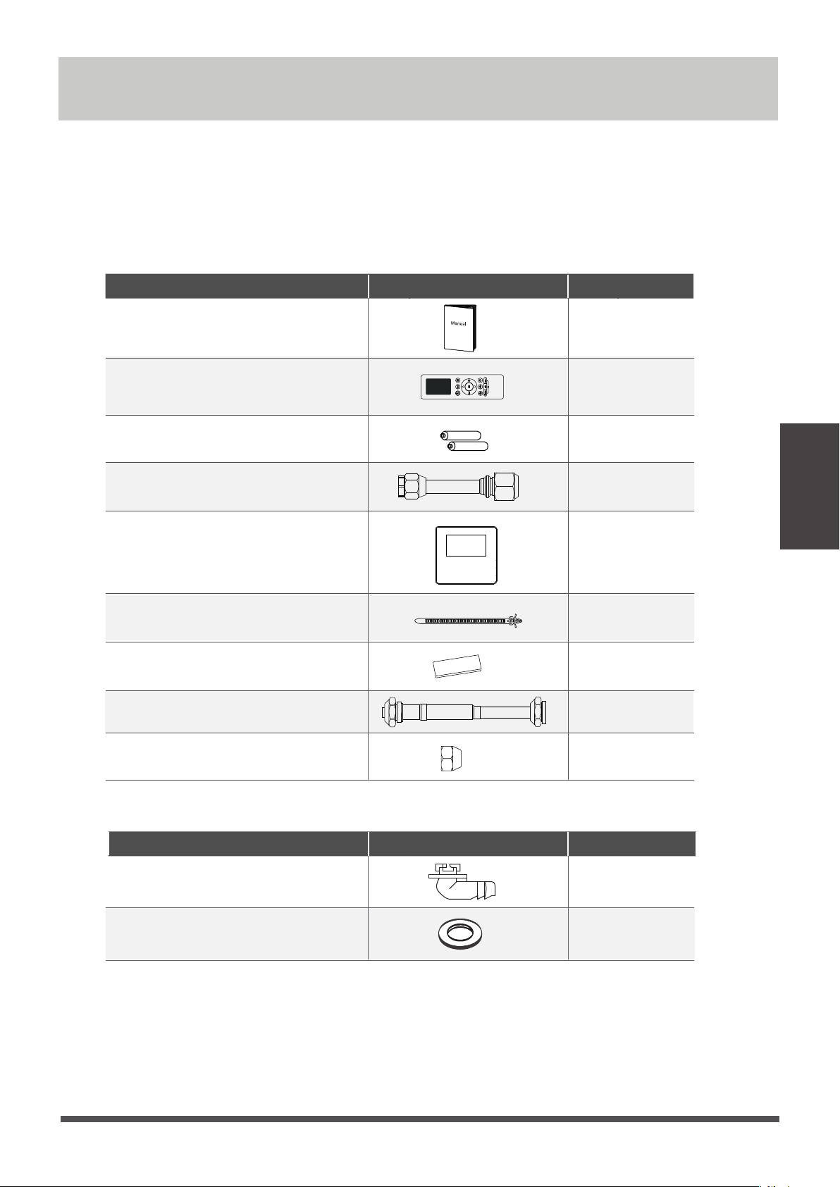
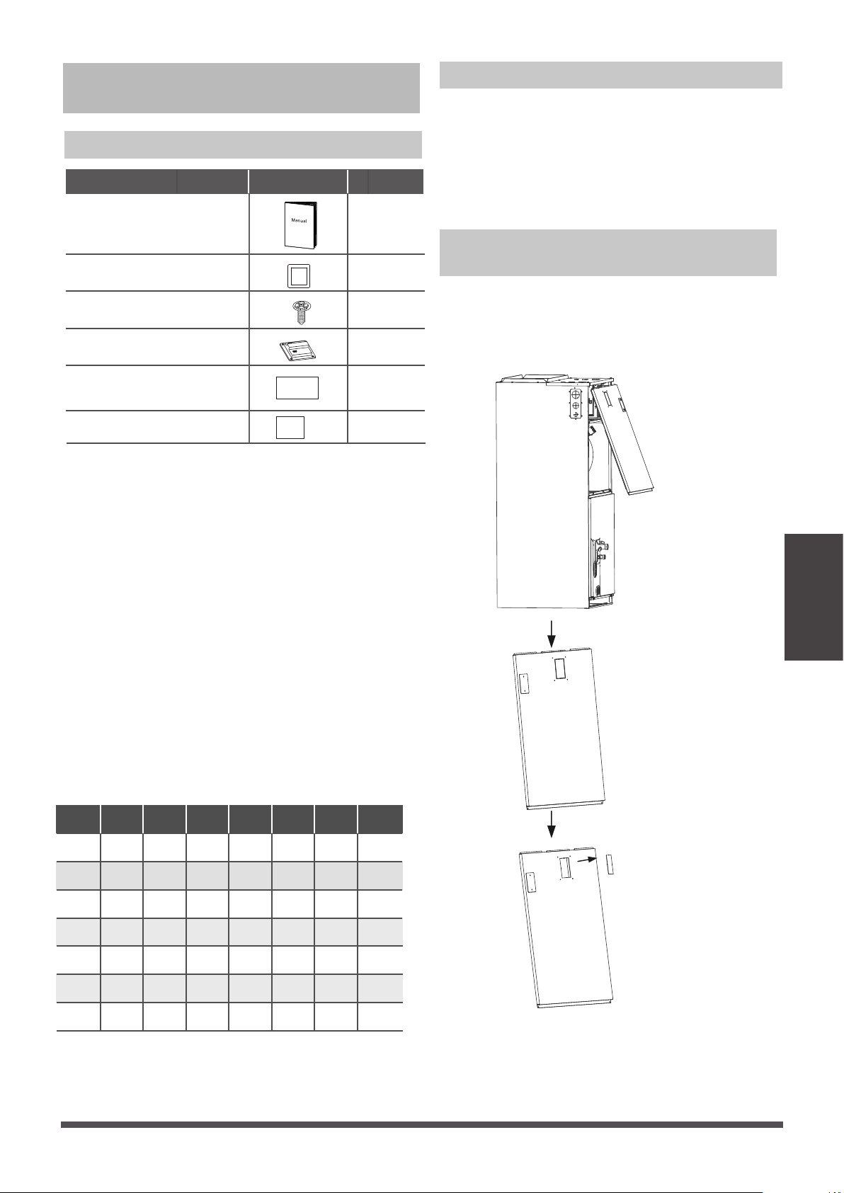
Accessories
The air condioning system comes with the following accessories. Use all of the installaon parts and
accessories to install the air condioner. Improper installaon may result in water leakage, electrical
shock and fire, or equipment failure.
Accessories (Packed with the indoor unit)
Accessories (Packed with the outdoor unit) (some models)
Accessories
NOTE :
The remote control is only used to adjust the parameters.
Owner’s Manual & Installaon Manual
Name Shape Quantity
2
Remote controller (some models)
1
2
1
1
2
Baery (some models)
Transfer connector (some models)
Wired controller (some models)
Fasten belt
1
4
Sponge
Name Shape Quantity
1
1
Drain joint (some models)
Seal (some models)
Transfer connector (some models)
2
Copper nut (some models)
Page 15
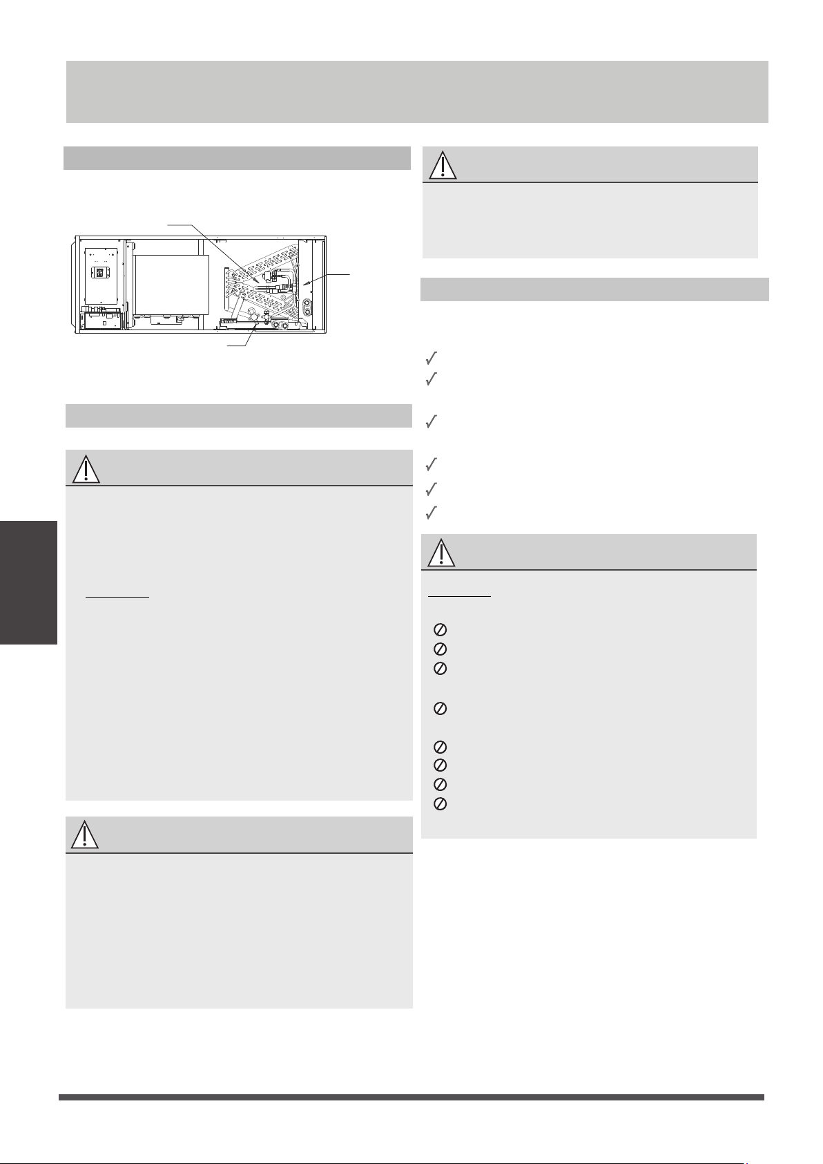
Indoor Unit Installation
Indoor Unit Parts
coil compartment (Access panel Removed)
Upflow drain pan
Horizontal drain pan
Page 16
Indoor Unit
Installation
Safety Precautions
WARNING
• Securely install the indoor unit on a structure
that can sustain its weight. If the structure is
too weak, the unit may fall and cause personal
injury, unit and property damage, or death.
•
•
DO NOT install the indoor unit in a bathroom
or laundry room as excessive moisture can
short the unit and corrode the wiring.
CAUTION
• Install the indoor and outdoor units, cables
and wires at least 3.2’ (1m) from televisions
or radios to prevent stac or image distoron.
Depending on the appliances, a 3.2’ (1m)
distance may not be sufficient.
• If the indoor unit is installed on metal, it must
be electrically grounded.
Indoor Unit Installation Instructions
The indoor unit should be installed in a locaon
that meets the following requirements:
Enough room for installaon and maintenance.
Enough room for the connecng pipe and
drainpipe.
The ceiling is horizontal and its structure can
sustain the weight of the indoor unit.
The air inlet and outlet are not impeded.
The airflow can fill the enre room.
There is no direct radiaon from heaters.
IMPORTANT
Danger of explosion. Keep flammable materials
and vapors, such as gasoline, away from air
handler. Place air handler so that heang
elements are at least 18 inches (46 cm) above
the floor for a garage installaon. Failure to
follow these instrucons can result in death,
explosion, or fire.
Please apply sealant around the places where
the wires, refrigerant pipes and condensate
pipes enter the cabinet.
CAUTION
DO NOT install the unit in the following
Areas with oil drilling or fracking
Coastal areas with high salt content in the air
Areas with causc gases in the air, such as
near hot springs
Areas with power fluctuaons, such as
factories
Enclosed spaces, such as cabinets
Areas with strong electromagnec waves
Areas that store flammable materials or gas
Rooms with high humidity, such as
bathrooms or laundry rooms
locaons:
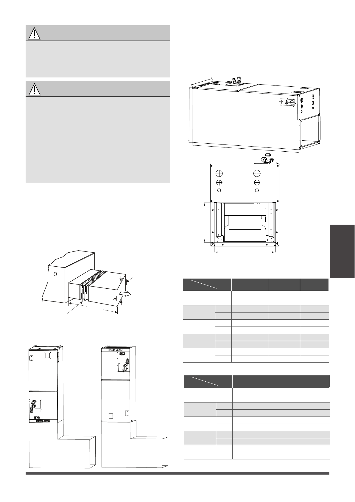
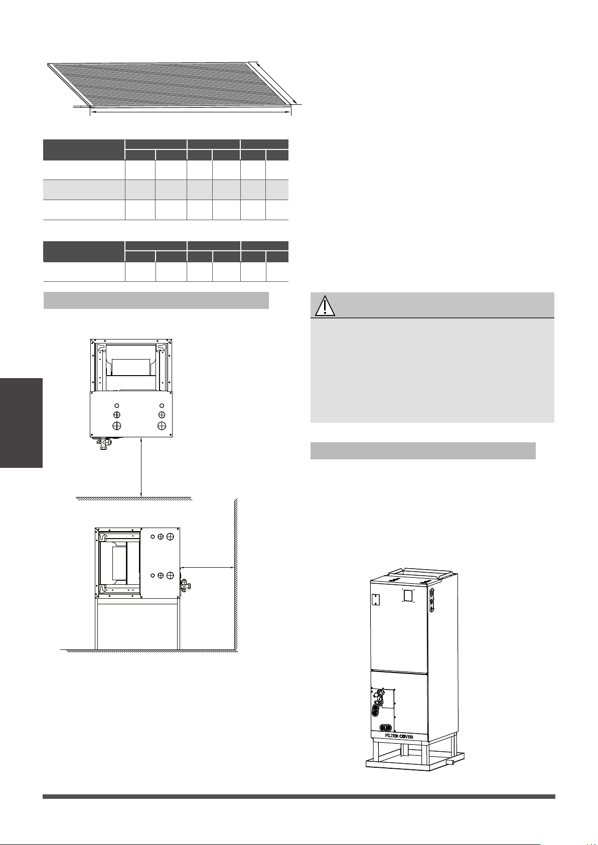
RECOMMENDED DISTANCES BETWEEN THE
INDOOR UNIT
The distance between the mounted indoor unit
should meet the specificaons illlustrated in the
following diagram.
Plenum Clearances
MINIMUM CLEARANCE
OF 1″/25.4mmALL SIDES
FLEXIBLE
DUCT COLLAR
The outlet side pipe length is 59’’/1.5m.
59’’/1.5m
Indoor parts installation size
MODEL(Btu/h)
Dimensions
Length of A
Length of B
12K~24K
1143
533
Length of C
Length of D
Length of E
445
400
260
30K~48K
1245
533
534
490
260
60K
1346
45
49 53
533
21
21 21
622
17-1/2
21-1/50 24-1/2
580
15-3/4
19-5/16 22-27/32
260
10-1/4 10-1/4 10-1/4
Vertical installations
Horizontal installations
A
B
C
E
D
mm
inch
mm
inch
mm
inch
mm
inch
mm
inch
MODEL(Btu/h)
Dimensions
Length of A
Length of B
60K
Length of C
Length of D
Length of E
1245
533
534
490
260
49
21
21-1/50
19-5/16
10-1/4
mm
inch
mm
inch
mm
inch
mm
inch
mm
inch
Page 17
Indoor Unit
Installation
(unit: inch/mm)
Model A(for North America models)
Model B
Fixing instructions: When installed vercally
(upward or downward), the lower end of the air
outlet needs to be connected to the L-shaped
metal air duct and fastened by screws.
WARNING
IMPORTANT
Use duct tape and/or Permagum to seal closed
any space around the holes where the drain lines
exit the cabinet. Warm air must not be allowed
to enter throughany gaps or holes in the cabinet.
There must be an airght seal between the
boom of the air handler and the return air
plenum. Use fiberglass sealing strips, caulking,
or equivalent sealing method between the
plenum and the air handler cabinet to ensure a
ght seal. Return air must not be drawn from a
room where this air handler or any gas-fueled
appliance (i.e., water heater), or carbon
monoxide-producingdevice (i.e., wood fireplace)
is installed.
D
t
Recommended size of lter
Mount positions
Installation place
The units can be installed in a vercal (down
and up)and Horizontal(right and le)
configuraon.
Vertical up installations
Vertical installations
Horizontal installations
24inch(min)
24inch(min)
Page 18
Indoor Unit
Installation
W
MODEL(Btu/h)
12-24K
30-48K
W
16
495.3
60K 584.2
D
20
20
20
508
508
508
t
1
1
1
25.4
24.4
25.4
(unit: inch/mm)
406.4
19-1/2
23
inch mm inch mm inch mm
Model A(for North America models)
MODEL(Btu/h)
60K
W
495.3
D
508
20
t
25.4
1
19-1/2
inch mm inch mm inch mm
Model B
IMPORTANT
A field-fabricated secondary drain pan, with a
drain pipe to the outside of the building, is
required in all installaons over a finished living
space or in any area that may be damaged by
overflow from the main drain pan. In some
localies, local codes may require a secondary
drain pan for any horizontal installaon.
DUCT CONNECTIONS:Air supply and return
may be handled in one of several ways best suited
to the installaon (See table for dimensions for
duct inlet and outlet connecons). The vast majority
of problems encountered with combinaon cooling
systems can be linked toimproperly designed or
installed duct systems, it is therefore highly
important to the success of an installaon that the
duct system be properly designed and installed.
Use flexible duct collars to minimize the transmission
of vibraon/noise into the condioned space.
Where return air duct is short, or where sound is
liable to be a problem, sound absorbing glass fiber
should be used inside the duct. Insulaon of duct
work is a must where it runs through an uncooled
space during the cooling season. The use of a vapor
barrier is recommended to prevent absorpon of
moisture from the surrounding air into the insulaon.
The supply air duct should be properly sized by
use of a transion to match unit opening. All ducts
should be suspended using flexible hangers and
never fastened directly to the structure. This unit
is not designed for nonducted (freeblow)
applicaons. Duct work should be fabricated and
installed in accordance with local and/or naonal
switchs.
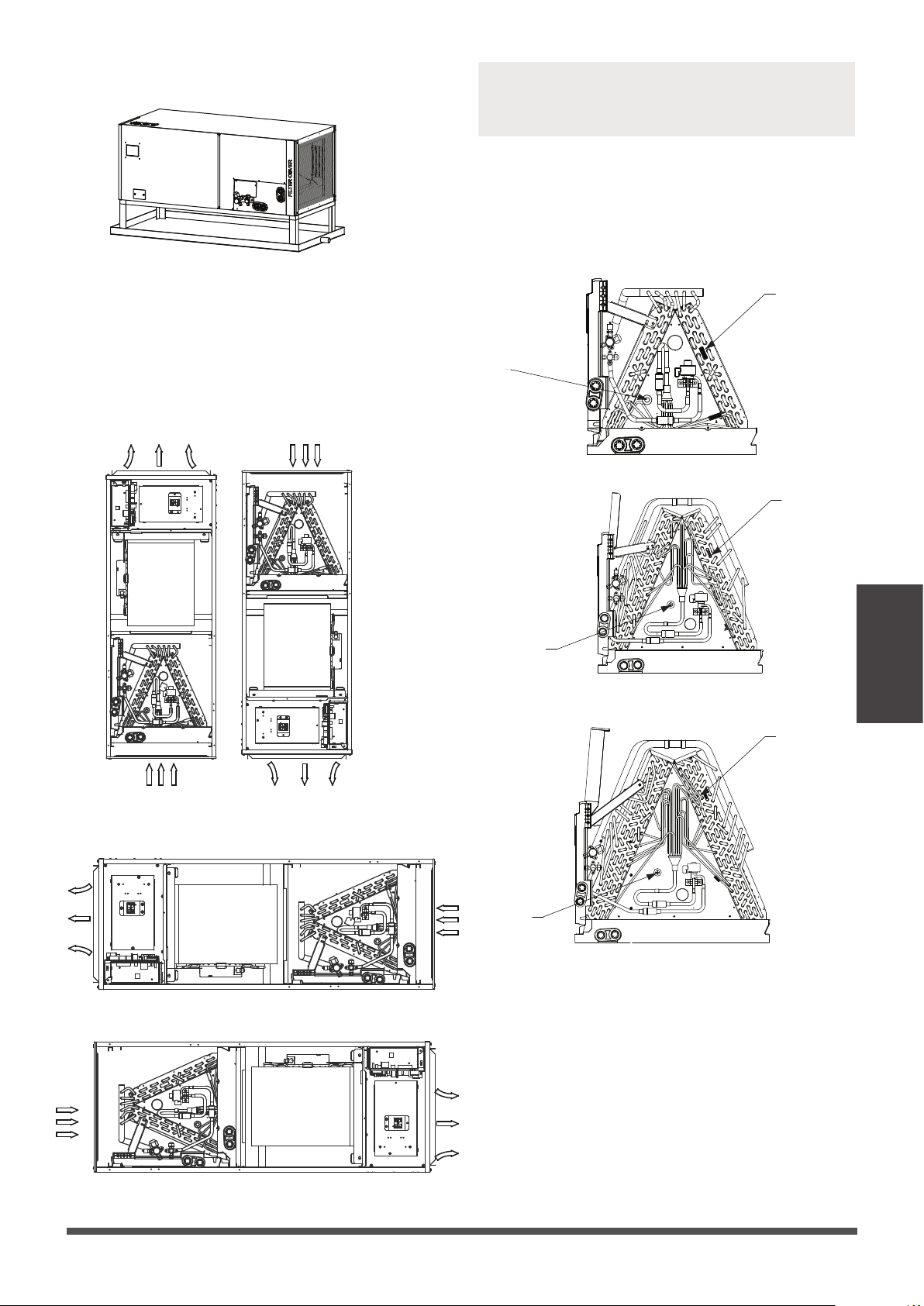
Horizontal installations
T2:Evaporator central temperature sensor
T1:room temperature sensor (some models)
The unit may be installed in one of the upflow,
downflow, horizontal le or horizontal right
orientaons .
Indicaon of the posion of each temperature
temperature sensor of the evaporator:
12-24K model
30-48K model
60K model
downflowupflow
horizontal le
horizontal right
T2
T1
T2
T1
T2
T1
Page 19
Indoor Unit
Installation
NOTE: For installaon, an drain pan (not supplied)
must be installed.
NOTE: Vercal up and horizontal
le
installaon
does not need to change thedirecon of
evaporator.
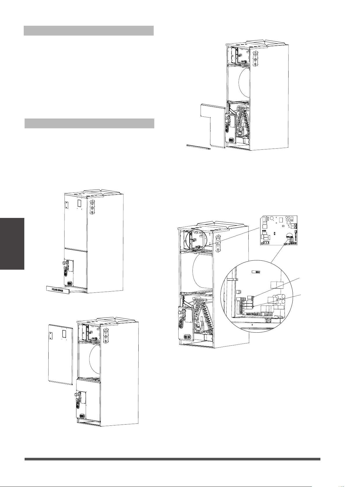
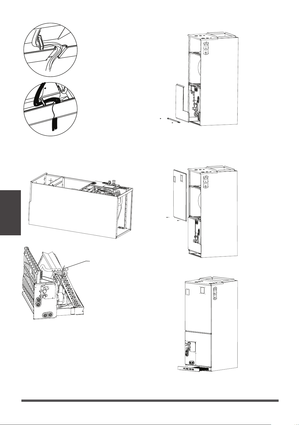
Please follow these steps to perform Vercal
up installaon and Horizontal le installaon:
1. Open the upper cover.
2.
Open the cover of the electronic control box.
3. Connect the wire according to the wiring
diagram.
4. Connect the pipes.
5. Install the drainage pipes.
For the Horizontal right installaon and Vercal
down installaon, the direcon of the evaporator
should be changed . Please do it according to the
following steps:
1. Remove the cover plate of the filter ,then take
the filter off.
2. Remove the upper cover assembly.
3. Remove evaporator cover plate.
4. Remove T1, T2 temperature sensor plug、
electronic expansion valve wiring
Disassemble T1, T2 temperature sensor and
electronic expansion valve
Regular installation instructions
Reversing installation instructions
T2
T1
Page 20
Indoor Unit
Installation
NOTE: T1 is only available for some models.
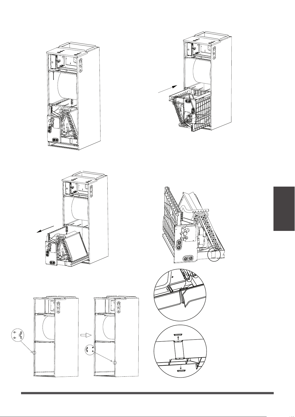
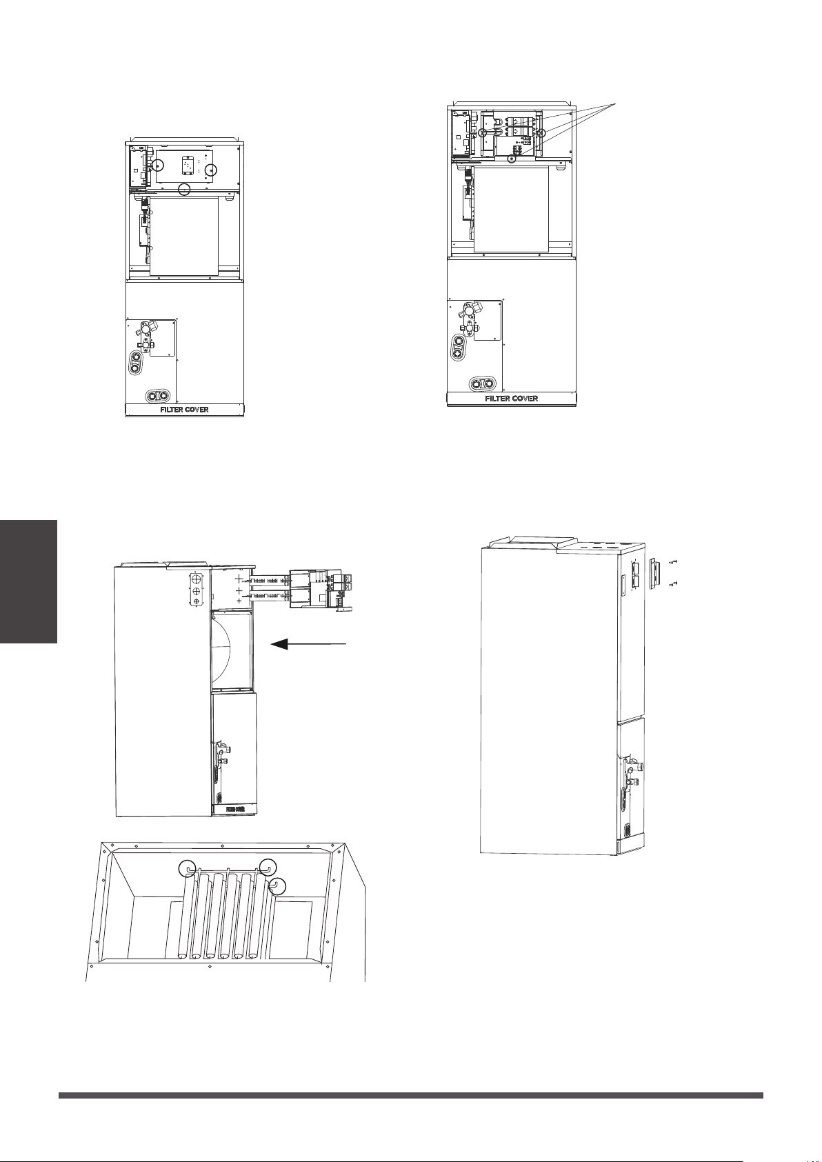
5. Remove T1、T2 temperature sensor and
electronic expansion valve wire es.
6. Take out the evaporator and drain pan and
rotate 180°.
8. Reinstall the evaporator and drain pan.
7. Adjust the posion of the mounng parts.
9. Reinstall T1, T2 temperature sensor plug
electronic expansion valve and e up the
temperature sensor wires.
NOTE: The wire body needs to pass through the
wire groove from the water receiving tray and be
stuck on the hook of the water receiving tray.
Break the sponge.
Remove knockouts as
shown in the figure.
Page 21
Indoor Unit
Installation
10. The evaporator is assembled in place.
11. Reinstal evaporator cover plate.
12. Connect the wire according to the wiring
diagram.
13. Reassemble the upper cover.
14. Reinstal the filter and filter cover plate.
15. Connect the pipes.
16. Install the drainage pipes.
Use cable es to bind and
fix the environmental
temperature sensive bag
as shown in the figure.
Hook the wire into the
buckle and go down
from the wire slot.
Sponge paste reset.
Page 22
Indoor Unit
Installation
Installation of Electric Auxiliary Heat Module
(for some models)(not supplied)
Electric auxiliary heang
wiring diagram
Air switch label
NOTE:
Installaon must be performed by an authorized
dealer or specialist. Please make necessary
protecon when installing the unit.
Specificaon series of electric auxiliary heat
module:
3kW, 5kW, 8kW, 10kW, 15kw, 20kW, 25kW.
The electric auxiliary heat module is only used
for installaon on the AHU internal machine.
If the unit needs to be equipped with electric
auxiliary heat module, please check the electric
auxiliary heat module specificaon that can be
matched with the unit first to avoid unnecessary
consequences caused by improper matching.
Accessories
Name Shape Quantity
Owner’s and Installaon
manual
1
Rubber cap
1
1
1
1
Seal sponge
Screw 7
Selecon and matching of internal machine and
electric auxiliary heang components
48K
- - Y Y Y Y -
- - - Y Y Y Y
60K
MODEL
(Btu/h)
12K
18K
3kW
Y Y Y - - - -
Y Y Y Y - - -
- Y Y Y Y - -
24K
5kW 8kW 10kW 15kW 20kW 25kW
30K
- Y Y Y Y - -
- Y Y Y Y Y -
36K
Before installaon, please check the list of electric
auxiliary heat modules and physical objects. Aer
transportaon, check whether the electric heang
is damaged. If any damage is found, please contact
the aer-sales personnel immediately.
1. Remove the upper cover and use professional
tools to destroy the knock-out holes of the
upper cover.
Installation Requirements
Electric Auxiliary Heat Module installation
and wiring operation
Indoor Unit
Installation
Page 23
2. Remove the terminal block and power cord,
loosen the screws, and remove the electric
auxiliary heang cover.
3. Install the electric auxiliary heang component
into the chassis shell along the front direcon,
and note that the front end needs to be inserted
into the shell assembly hole.
4. Tighten the fixing screws.
screws
5. Wiring according to the wiring nameplate.
6. Install the upper cover.
7. Install waterproof case.
Indoor Unit
Installation
Page 24
Page 25
Indoor Unit
Installation
15kw
20kW
3kW
10kW
Aer the electric heang wiring is connected,
please confirm before power on:
Check all wiring and ensure reliable connecon
of wire body.
Check the electric heang fixing screw, and the
screw is fixed reliably.
The size selecon of power wire meets the
power supply requirements.
1 1 2
1 2
2 3 3
2 3 3
2
3
4
25kW
3 4 45
2
2
5kW 1 1 2 2
8kW 1 2 2 2
Specications
Number
of circuit
breakers
Number
of relays
Number of
power cord
groups
Number of
power cord
grounding
screws
NOTE:
Electric auxiliary heang wiring diagram packed
with the accessories.
Please paste the wiring diagram in the inside
cover aer the installaon of electric auxiliary
heang modules is completed ,for convenience
of later maintenance.
NOTE:
Aer installing the electric auxiliary heat module ,
sck the air switch label near the upper cover air
switch.
•
•

Page 26
Indoor Unit
Installation
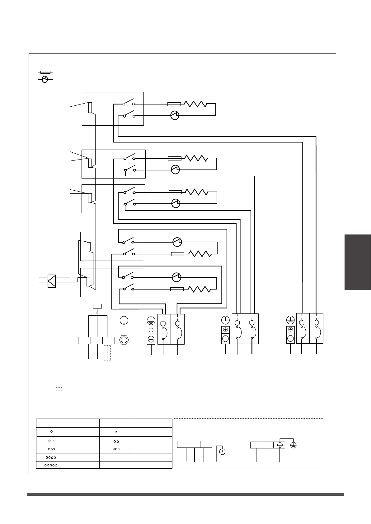
Electric auxiliary heang wiring diagram
Round hole number Relay number
CB1
:thermal cut-out
:thermal link, self-reseng
3KW/5KW HEAT KIT
:thermal cut-out
:thermal link, self-reseng
8KW/10KW HEAT KIT
15KW HEAT KIT
:thermal cut-out
:thermal link, self-reseng
:thermal cut-out
:thermal link, self-reseng
20KW HEAT KIT
Round hole number
Round hole number Relay number
RELAY 1
RELAY 2
RELAY 1
RELAY 2
Round hole number
CB1
Round hole number Relay number
RELAY 1
RELAY 2
RELAY 1
RELAY 2 CB2
Round hole number
RELAY 4
Round hole number Relay number
RELAY 1
RELAY 2
Circuit breaker number
RELAY 1
RELAY 2 CB2
Round hole number
RELAY 3
RELAY 4
RELAY 1
CB1
CB1
3(S)
1(L1)
2(L2)
TYPE A
L1
L2
TYPE B
Y/G
3(S)
1(L1)
2(L2)
TYPE A
L1
L2
TYPE B
Y/G
3(S)
1(L1)
2(L2)
TYPE A
L1
L2
TYPE B
Y/G
3(S)
1(L1)
2(L2)
TYPE A
L1
L2
TYPE B
Y/G
Circuit breaker number
Circuit breaker number
Circuit breaker number
NOTE2:
Please aach the nameplate to the cover of
the electric control box. All the round holes
located on the plate represent numbers. Please
refer to the Installaon Manual for details.
NOTE1:
This symbol indicates the element is
oponal, The wiring type of the actual
unit shall prevail.
NOTE3: TO BE WIRED IN ACCORDANCE WITH NEC
AND LOCAL CODES.
NOTE4: POWER A,B,C,D ARE DIFFERENT POWERS.
NOTE2:
Please aach the nameplate to the cover of the
electric control box. All the round holes located
on the plate represent numbers. Please refer to
the Installaon Manual for details.
NOTE1:
This symbol indicates the element is oponal,
The wiring type of the actualunit shall prevail.
NOTE3: TO BE WIRED IN ACCORDANCE WITH NEC
AND LOCAL CODES.
NOTE4: POWER A,B,C,D ARE DIFFERENT POWERS.
NOTE2:
Please aach the nameplate to the cover of the
electric control box. All the round holes located
on the plate represent numbers. Please refer to
the Installaon Manual for details.
NOTE1:
This symbol indicates the element is oponal,
The wiring type of the actual unit shall prevail.
NOTE3: TO BE WIRED IN ACCORDANCE WITH NEC
AND LOCAL CODES.
Y/G
Y/G
Y/G
Y/G
RED
YELLOW
BLACK
3
24V~
Aux-Heat
control signal
RED
RELAY1
RED
BLACK
BLACK
TO INDOOR UNIT
MAINBOARD
cn12
TO INDOOR UNIT
MAINBOARD
cn11
L1
L2
CB1
3(S)
1(L1)
2(L2)
POWER A
RED
BLACK
HTR1
0000000000000000
1111111
2 4
6 8
2 4
6 8
2 4
6 8
2 4
6 8
2 4
6 8
2 4
6 8
2 4
6
2 4
6
L2
L1
CB CB
TCO1
TL1
POWER B
(green)
Y/G
Y/G
RED
YELLOW
BLACK
3
BLACK
BLACK
RED
RED
RELAY2
RELAY1
BLACKRED
RED
BLACK
0
1
0
1
0
1
0
0
1
2 4
6
8
0
1
2 4
6
8
0
1
2 4
6
8
0
1
2 4
6
8
0
1
2 4
6
8
0
1
2 4
6
8
0
1
2 4
6
8
0
2 4
6
8
Aux-Heat
control signal
24V~
TO INDOOR
UNIT MAIN
BOARD CN12
TO INDOOR UNIT
MAINBOARD
CN11
3(S)
1(L1)
2(L2)
2 4
6 8
2 4
6 8
2 4
6 8
2 4
6 8
2 4
6 8
2 4
6 8
2 4
6 8
2 4
6 8
RED
BLACK
HTR1
TCO1
TL1
RED
BLACK
HTR2
TCO2
TL2
L1
L2
CB1
L2
L1
CB CB
POWER A POWER B
(green)
Y/G
Y/G
RED
YELLOW
BLACK
3
BLACK
BLACK
RED
RED
RED
RELAY4
RELAY1
RELAY2
BLACK
BLACK
BLUE
0
1
2
4
6
8
0
1
2
4
6
8
0
1
2
4
6
8
1
2
4
6
8
0
1
0
1
0
1
0
1
0
1
0
1
0
1
0
1
1
2
4
6
8
1
2
4
6
8
1
2
4
6
8
2
4
6
0
1
0
1
0
1
0
1
0
1
0
1
0
1
0
1
RED
Aux-Heat
control signal
24V~
TO INDOOR UNIT
MAINBOARD
CN11
TO INDOOR
UNIT MAIN
BOARD
CN12
BLACK
BLACKRED
BLACK
3(S)
1(L1)
2(L2)
0000000000000000
1111111
RED
BLACK
HTR1
TCO1
TL1
2
4
6
8
2
4
6
8
2
4
6
8
2
4
6
8
2
4
6
8
2
4
6
8
2
4
6
8
2
4
6
RED
BLACK
HTR2
TCO2
TL2
RED
BLACK
HTR3
2 4
6 8
2 4
6 8
2 4
6 8
2 4
6 8
2 4
6 8
2 4
6 8
2 4
6
2 4
6
TCO3
TL3
L1
L2
CB1
L2
L1
CB CB
L1
L2
L2
L1
CB CB
CB2
POWER A
POWER B POWER C
(green)
Y/G
Y/G
Y/G
NOTE4: POWER A,B,C,D ARE DIFFERENT POWERS.
The wiring mode of power supply A shall be
based on the type of original wiring terminal of
AHU; for type A, S posion must be connected
to the ourdoor S; for type B, S posion shall not
be connected.
The wiring mode of power supply A shall be
based on the type of original wiring terminal of
AHU; for type A, S posion must be connected
to the ourdoor S; for type B, S posion shall not
be connected.
The wiring mode of power supply A shall be
based on the type of original wiring terminal of
AHU; for type A, S posion must be connected
to the ourdoor S; for type B, S posion shall not
be connected.
The wiring mode of power supply A shall be
based on the type of original wiring terminal of
AHU; for type A, S posion must be connected to
the ourdoor S; for type B, S posion shall not be
connected.
RED
YELLOW
BLACK
3
RED
RED
BLACK
BLACK
RED
RED
RELAY3
RELAY4
RELAY2
RELAY1
RED BLACK
BLACK
RED
BLUE
BLACK
RED
Aux-Heat
control signal
0
2 4
0
2 4
0
2 4
0
2 4
0
1
0
1
0
1
0
1
0
1
0
1
0
1
0
1
0
2 4
0
2 4
0
2 4
2 4
0
1
0
1
0
1
0
1
0
1
0
1
0
1
0
1
0
2
4
8
0
2
4
8
0
2
4
8
0
2
4
8
0
1
4
0
1
4
0
1
4
0
1
4
0
1
4
0
1
4
0
1
4
0
1
4
0
2
4
8
0
2
4
8
0
2
4
8
0
2
4
8
0
1
4
0
1
4
0
1
4
0
1
4
0
1
4
0
1
4
0
1
4
0
1
4
0
2
4
8
0
2
4
8
0
2
4
8
0
2
4
8
0
1
4
0
1
4
0
1
4
0
1
4
0
1
4
0
1
4
0
1
4
0
1
4
0
2
4
8
0
2
4
8
0
2
4
8
0
2
4
8
0
1
4
0
1
4
0
1
4
0
1
4
0
1
4
0
1
4
0
1
4
0
4
24V~
TO INDOOR UNIT
MAINBOARD
CN11
TO INDOOR
UNIT MAIN
BOARD
CN12
RED
BLACK
BLACK
BLACK
BLACK
3(S)
1(L1)
2(L2)
1111111111111111
6 86 86 86 86 86 86 86 86 86 86 86 86 86 86 86 8
6666666666666666
8888888888888888 6666666666666666
2222222222222222
1111111111111111111111111111111
L1
L2
CB1
L2
L1
CB CB
L1
L2
CB2
L2
L1
CB CB
RED
BLACK
RED
BLACK
HTR4
TCO4
TL4
HTR3
TCO3
TL3
HTR1
TCO1
TL1
RED
BLACK
HTR2
TCO2
TL2
2 42 42 42 42 42 42 42 4
6 86 86 86 86 86 86 86 86 86 86 86 86 86 86 86 8
POWER A
POWER B POWER C
(green)
Y/G
Y/G
Y/G
Page 27
Indoor Unit
Installation
Electric auxiliary heang wiring diagram
: thermal cut-out
: thermal link, self-reseng
25KW HEAT KIT
Round hole number
Relay number
RELAY 1
RELAY 2
Relay number
RELAY 1
RELAY 2
CB3
Round hole number
RELAY 3
CB2
RELAY 4
RELAY 5
CB1
3(S)
1(L1)
2(L2)
TYPE A
L1
L2
TYPE B
Y/G
Circuit breaker number
NOTE2:
Please aach the nameplate to the cover of
the electric control box. All the round holes
located on the plate represent numbers. Please
refer to the Installaon Manual for details.
NOTE1
:
This symbol indicates the element is
oponal, The wiring type of the actual
unit shall prevail.
NOTE3: TO BE WIRED IN ACCORDANCE
WITH NEC AND LOCAL CODES.
NOTE4: POWER A,B,C,D ARE DIFFERENT
POWERS.
Y/G
3(S)
RED
1(L1)
2(L2)
YELLOW
BLACK
3
RED
BLACK
BLACK
BLACK
BLACK
RELAY5
0
4
0
4
BLACK
BLACK
BLACK
RED
RED
RED
RED
RED
RED
BLACK
BLUE
RED
RELAY3
RELAY4
RELAY2
RELAY1
Aux-Heat
control signal
0
1
2 4
0
1
2 4
0
1
2 4
0
1
2 4
0
1
2
4
6 8
0
1
2
4
6 8
0
1
2
4
6 8
0
1
2
4
6 8
0
1
2
4
6 8
0
1
2
4
6 8
0
1
2
4
6 8
0
1
2
4
6 8
0
1
2 4
0
1
2 4
0
1
2 4
0
1
2 4
0
1
2
4
6 8
0
1
2
4
6 8
0
1
2
4
6 8
0
1
2
4
6 8
0
1
2
4
6 8
0
1
2
4
6 8
0
1
2
4
6 8
0
1
2
4
6 8
0
2
4
8
0
2
4
8
0
2
4
8
0
2
4
8
0
1
4
0
1
4
0
1
4
0
1
4
0
1
4
0
1
4
0
1
0
1
0
2
4
8
0
2
4
8
0
2
4
8
0
2
4
8
0
1
0
1
0
1
0
1
0
1
0
1
0
1
0
1
0
2
4
8
0
2
4
8
0
2
4
8
0
2
4
8
0
1
0
1
0
1
0
1
0
1
0
1
0
1
0
1
0
2
4
8
0
2
4
8
0
2
4
8
0
4
8
0
1
0
1
0
1
0
1
0
1
0
1
0
1
0
24V~
TO INDOOR UNIT
MAINBOARD
CN12
TO INDOOR UNIT
MAINBOARD
CN11
BLACK
BLACK
RED
RED
RED
BLACK
8888888888888888
6666666666666666
222222222222222
BLACK
BLACK
1111111111111111111111111111111
1111111111111111111111111111111
6666666666666666
8888888888888888
22222222
8888888888888888
6666666666666666
6666666666666666
L1
L2
CB1
L2
L1
CB CB
L1
L2
CB2
L2
L1
CB CB
L1
L2
CB3
L2
L1
CB CB
RED
BLACK
HTR5
TCO5
TL5
RED
BLACK
HTR4
TCO4
TL4
RED
BLACK
HTR3
TCO3
TL3
HTR1
TCO1
TL1
HTR2
TCO2
TL2
POWER A POWER B
POWER C
POWER D
Y/G
(green)
Y/G
Y/G
Y/G
The wiring mode of power supply A shall be based on the type of original
wiring terminal of AHU; for type A, S posion must be connected to the
ourdoor S; for type B, S posion shall not be connected.
Outdoor Unit Installation
Page 28
Outdoor Unit
Installation
Installation Instructions – Outdoor unit
Step 1: Select installation location
Before installing the outdoor unit, you must
choose an appropriate locaon. The following are
standards that will help you choose an appropriate
locaon for the unit.
Proper installation locations meet the
following standards:
Meets all spaal requirements shown in Installaon
Space Requirements above.
Good air circulaon and venlaon
Firm and solid—the locaon can support the unit
and will not vibrate
Noise from the unit will not disturb others
Install the unit by following local switchs and
regulaons , there may be differ slightly between
different regions.
SPECIAL CONSIDERATIONS FOR EXTREME
WEATHER
If the unit is exposed to heavy wind:
Install unit so that air outlet fan is at a 90°
angle to the direcon of the wind. If needed,
build a barrier in front of the unit to protect it
from extremely heavy winds.
See Figures below.
Strong
wind
Strong wind
Strong wind
If the unit is frequently exposed to heavy
rain or snow:
Build a shelter above the unit to protect it
from the rain or snow. Be careful not to
obstruct air flow around the unit.
If the unit is frequently exposed to salty
air
(seaside):
Use outdoor unit that is specially designed
to resist corrosion.
Wind Baffle
Protected from prolonged periods of direct
sunlight or rain
Where snowfall is ancipated, take appropriate
measures to prevent ice buildup and coil
damage.
DO NOT
install unit in the following locations:
Near an obstacle that will block air inlets and
outlets
Near a public street, crowded areas, or where
noise from the unit will disturb others
Near animals or plants that will be harmed by
hot air discharge
Near any source of combusble gas
In a locaon that is exposed to large amounts of
dust
In a locaon exposed to a excessive amounts
of salty air
24in (60cm)
on righ
t
12in (30cm)
on le
79in (200cm)
in fron
t
12in (30cm)
from back wall
24in (60cm) above
Split Type Outdoor Unit
Outdoor Unit Types and Specificaons
Outdoor Unit
Installation
W
H
W
H
A
B
D
Page 29
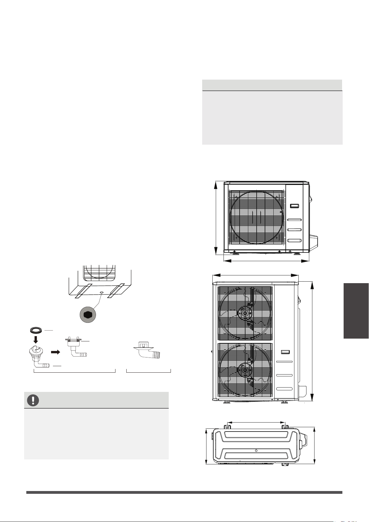
Step 2: Install drain joint (Heat pump unit
only)
Seal
Drain joint
(A) (B)
Base pan hole of
outdoor unit
Seal
IN COLD CLIMATES
In cold climates, make sure that the drain
hose is as vercal as possible to ensure
swi water drainage. If water drains too
slowly, it can freeze in the hose and flood
the unit.
Step 3: Anchor outdoor unit
The outdoor unit can be anchored to the
ground or to a wall-mounted bracket with
bolt(M10). Prepare the installaon base of
the unit according to the dimensions below.
UNIT MOUNTING DIMENSIONS
The following is a list of different outdoor
unit sizes and the distance between their
mounng feet. Prepare the installaon
base of the unit according to the dimensions
below.
Before bolng the outdoor unit in place, you must
install the drain joint at the boom of the unit.
NOTE: There are two different types of drain
joints depending on the type of outdoor unit.
If the drain joint comes with a rubber seal
(see Fig. A ), do the following:
1.
Fit the rubber seal on the end of the drain joint
that will connect to the outdoor unit.
2.
Insert the drain joint into the hole in the base
pan of the unit.
3.
Rotate the drain joint 90° unl it clicks in place
facing the front of the unit.
4.
Connect a drain hose extension (not included)
to the drain joint to redirect water from the
unit during heang mode.
If the drain joint doesn’t come with a rubber
seal (see Fig. B ), do the following:
1.
Insert the drain joint into the hole in the base
pan of the unit. The drain joint will click in
place.
2.
Connect a drain hose extension (not included)
to the drain joint to redirect water from the
unit during heang mode.
Outdoor Unit
Installation
If you will install the unit on the ground
or on a concrete mounting platform,
do the
following:
1.
Mark the posions for four expansion bolts
based on dimensions chart.
2.
Pre-drill holes for expansion bolts.
3.
Place a nut on the end of each expansion bolt.
4.
Hammer expansion bolts into the pre-drilled
holes.
5.
Remove the nuts from expansion bolts, and
place outdoor unit on bolts.
6.
Put washer on each expansion bolt, then
replace the nuts.
7.
Using a wrench, ghten each nut unl snug.
WARNING
WHEN DRILLING INTO CONCRETE, EYE
PROTECTION IS RECOMMENDED AT
ALL TIMES.
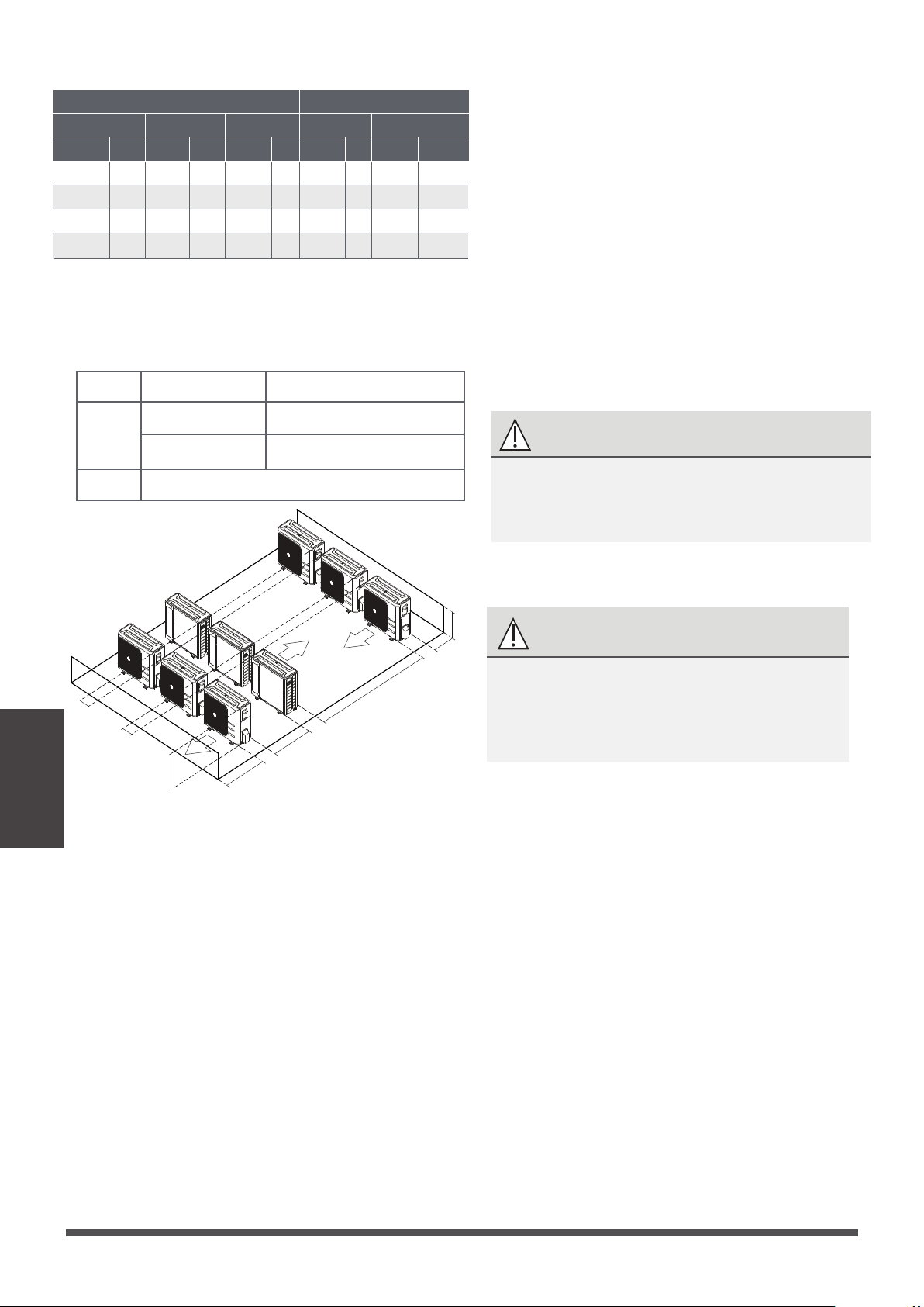
Page 30
L
H
118”/300 cm or more
A
23.6”/60 cm
or more
59”/150 cm
or more
9.8”/25 cm
or more
9.8”/25 cm
or more
Rows of series installation
L ≤ H
L ≤ 1/2H
L A
16in/25 cm / 9-13/ or more
1/2H < L ≤ H
16in/30 cm / 11-13 or more
L > H
Can not be installed
The relations between H, A and L are as follows.
(unit: inch/mm)
Outdoor Unit Dimensions
W
inch mm inch mm inch mm inch
mm
inch mm
H D
Mounting Dimensions
A B
805
317
31-11/16
554
330
511
12-1/2
946
403
37-1/4
810
410
673
15-7/8
952
404
37-1/2
1333
415
634
15-29/32
890
35
673
342
663
354
13-15/16
If you will install the unit on a wall-mounted
bracket , do the following:
1. Mark the posion of bracket holes based on
dimensions chart.
2. Pre-drill the holes for the expansion bolts.
3. Place a washer and nut on the end of each
expansion bolt.
4. Thread expansion bolts through holes in
mounng brackets, put mounng brackets
in posion, and hammer expansion bolts into
the wall.
5. Check that the mounng brackets are level.
6. Carefully li unit and place its mounng feet
on brackets.
7. Bolt the unit firmly to the brackets.
8. If allowed, install the unit with rubber gaskets
to reduce vibraons and noise.
CAUTION
Make sure that the wall is made of solid brick,
concrete, or of similarly strong material.
The wall must be able to support at
least four times the weight of the unit.
21-13/16
31-29/32
52-1/2
26-1/2
13
16-5/32
16-11/32
13-15/32
20-1/8
26-1/2
24-35/36
26-1/8
DO NOT pull the drainpipe forcefully. This
could disconnect it.
The drainpipe is used to drain water away from
the unit. Improper installaon may cause unit
and property damage.
CAUTION
•
Insulate all piping to prevent condensaon,
which could lead to water damage.
• If the drainpipe is bent or installed incorrectly,
water may leak and cause awater-level switch
malfuncon.
• In HEAT mode, the outdoor unit willdischarge
water. Ensure that the drain hoseis placed in
an appropriate area to avoidwater damage
and slippage.
•
NOTE ON PURCHASING PIPES
Installaon requires a polyethylene tube
(Internally threaded tube 3/4 inch), which can
be obtained at your local hardware store or
dealer.
Drainpipe Installation
Indoor Drainpipe Installation
1.
Cover the drainpipe with heat insulaon to
prevent condensaon and leakage.
VERTICAL DISCHARGE
PRIMARY DRAIN
These units operate with a posive pressure at
the drain connecons and a drain trap is required.
The trap needs to be installed as close to the unit
as possible. Make sure the top of the trap is below
the connecon to the drain pan to allow complete
drainage of the pan.
Drainpipe
Installation
IMPORTANT
Aer removal of drain pan plug(s), check
drain hole(s) to verify that drain opening is
fully open and free of any debris. Also check
to make sure that no debris has fallen into
the drain pan during installaon that may
plug up the drain opening.
Seal around the exing drain pipe, liquid
and sucon lines to prevent infiltraon of
humid air.
On units of this type, where the blower
“draws” rather than “blows” air through the
coil, traps must be installed in the condensate
drain lines (primary and auxiliary, if used).
Traps prevent the blower from drawing air
through the drain lines into the air supply.
Page 31
Main drain hole
Overflow drain hole
2.
Wall
IndoorOutdoor
≈ 12mm / 0.5 inch
NOTE: When drilling the hole, make sure to
avoid wires, plumbing, and other sensive
components.
3. Pass the drain hose through the wall hole.
Make sure the water drains to a safe locaon
where it will not cause water damage or a
slipping hazard.
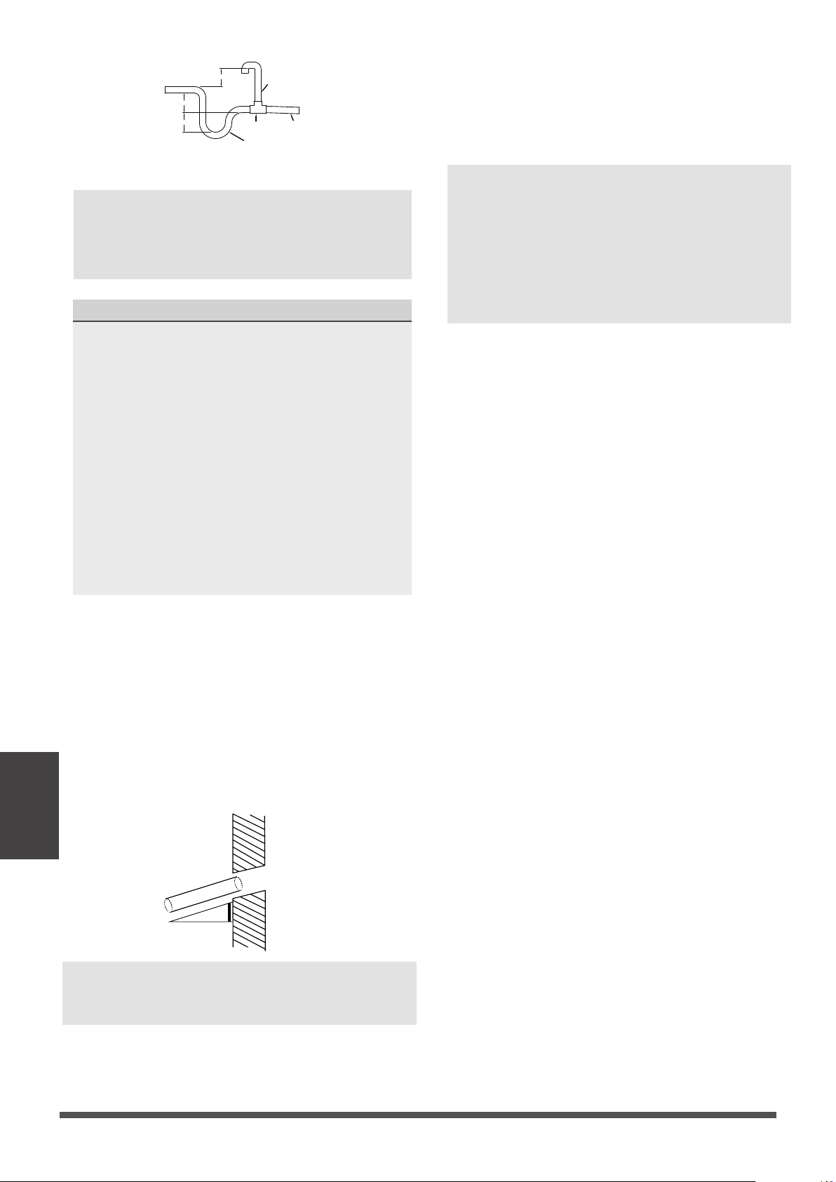
NOTE: The drainpipe outlet should be at least
1.9” (5cm) above the ground. If it touches the
ground, the unit may become blocked and
malfuncon. If you discharge the water directly
into a sewer, make sure that the drain has a U
or S pipe to catch odors that might otherwise
come back into the house.
NOTE:
Horizontal runs must also have an
an-siphon air vent(standpipe) install ahead
of the horizontal run to eliminate air
trapping.
Vent T
Anti-syphon
air vent
Lean over
1/50
Drain Trap
>2”(50mm)
Drainpipe
Installation
Page 32
NOTE ON DRAINPIPE INSTALLATION
•
When using an extended drainpipe, ghten
the indoor connecon with an addional
protecon tube to prevent it from pulling
loose.
• The Figure shows how to trap or plug all drains
during vercal discharge.
• The Figure shows how to trap or plugall drains
during right-hand discharge.
• The seal plug are supplied as accessories and
should be screwed ghtly only by hand.
• Incorrect installaon could cause water to
flow back into the unit and flood.
Using a 2.5” (65mm) core drill, drill a hole in
the wall. Make sure that the hole is drilled at
a slight downward angle, so that the outdoor
end of the hole is lower than the indoor end
by about 0.5” (12mm). This will ensure proper
water drainage . Place the
protecve wall cuff in the hole. This protects
the edges of the hole and will help seal it once
you finish installaon.
>2”(50mm)
>2”(50mm)
The Maximum Length And Drop
Height Based on Models. (Unit: m/ft.)
Type of model Capacity
(Btu/h)
Length of
piping
Maximum drop
height
North America,
Australia and the
eu frequency
conversion Split
Type
<15K 25/82 10/32.8
≥15K - <24K 30/98.4 20/65.6
≥24K - <36K 50/164 25/82
≥36K - ≤60K 65/213 30/98.4
Other Split Type
12K 15/49 8/26
18K-24K 25/82 15/49
30K-36K 30/98.4 20/65.6
42K-60K 50/164 30/98.4
Refrigerant Piping Connection
Safety Precautions
WARNING
• All field piping must be completed by a
licensed technician and must comply with
the local and naonal regulaons.
• When the air condioner is installed in a
small room, measures must be taken to
prevent the refrigerant concentraon in
the room from exceeding the safety limit
in the event of refrigerant leakage. If the
refrigerant leaks and its concentraon
exceeds its proper limit, hazards due to
lack of oxygen may result.
• When installing the refrigeraon system,
ensure that air, dust, moisture or foreign
substances do not enter the refrigerant
circuit. Contaminaon in the system may
cause poor operang capacity, high
pressure in the refrigeraon cycle,
explosion or injury.
• Venlate the area immediately if there is
refrigerant leakage during the installaon.
Leaked refrigerant gas is both toxic and
flammable. Ensure there is no refrigerant
leakage aer compleng the installaon
work.
Notes On Pipe Length and Elevation
Ensure that the length of the refrigerant pipe, the
number of bends, and the drop height between
the indoor and outdoor units meets the
requirements shown in the following table:
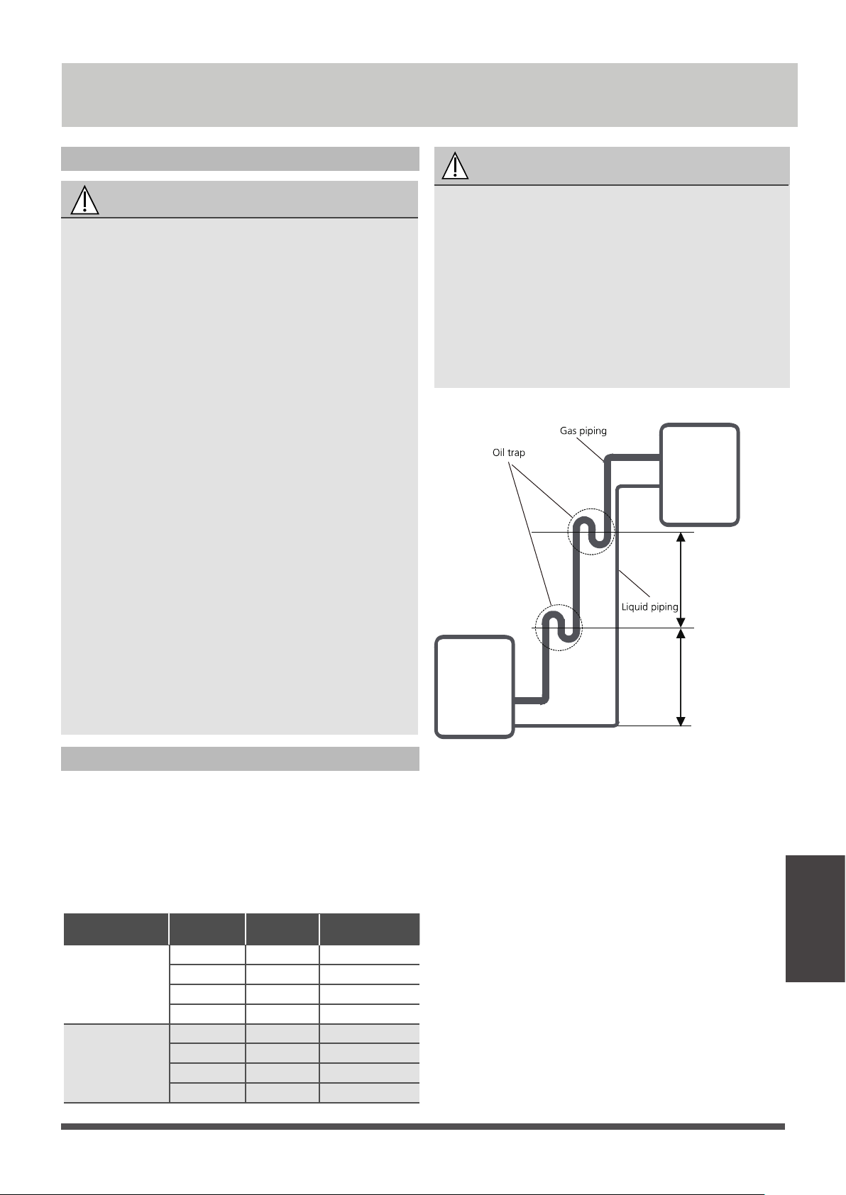
Oil traps
CAUTION
If oil flows back into the outdoor unit’s
compressor, this might cause liquid compression
or deterioraon of oil return. Oil traps in the
rising gas piping can prevent this.
An oil trap should be installed every 20 (6m) of
vercal sucon line riser (<36000Btu/h unit).
An oil trap should be installed every 32.8 (10m)
of vercal sucon line riser (≥36000Btu/h unit).
10m/32.8
(≥36000Btu/h unit)
20/6m
(<36000Btu/h unit)
10m/32.8
(≥36000Btu/h unit)
20/6m
(<36000Btu/h unit)
Indoor unit/
Outdoor unit
Indoor unit/
Outdoor unit
Refrigerant piping
Connection
Page 33
Refrigerant piping
Connection
Page 34
Name
Shape Quantity(PC)
Parts you must purchase
separately. Consult the dealer
about the proper pipe size of
the unit you purchased.
Connecting pipe
assembly
Liquid side
Gas side
Φ
1/4 i n(6.35)
Φ 3/8in(9.52)
Φ 5/8in(16)
Φ 1/ 2in(12.7)
Φ 3/4in(19)
Φ 7/8in(22)
Connection Instructions –
Refrigerant Piping
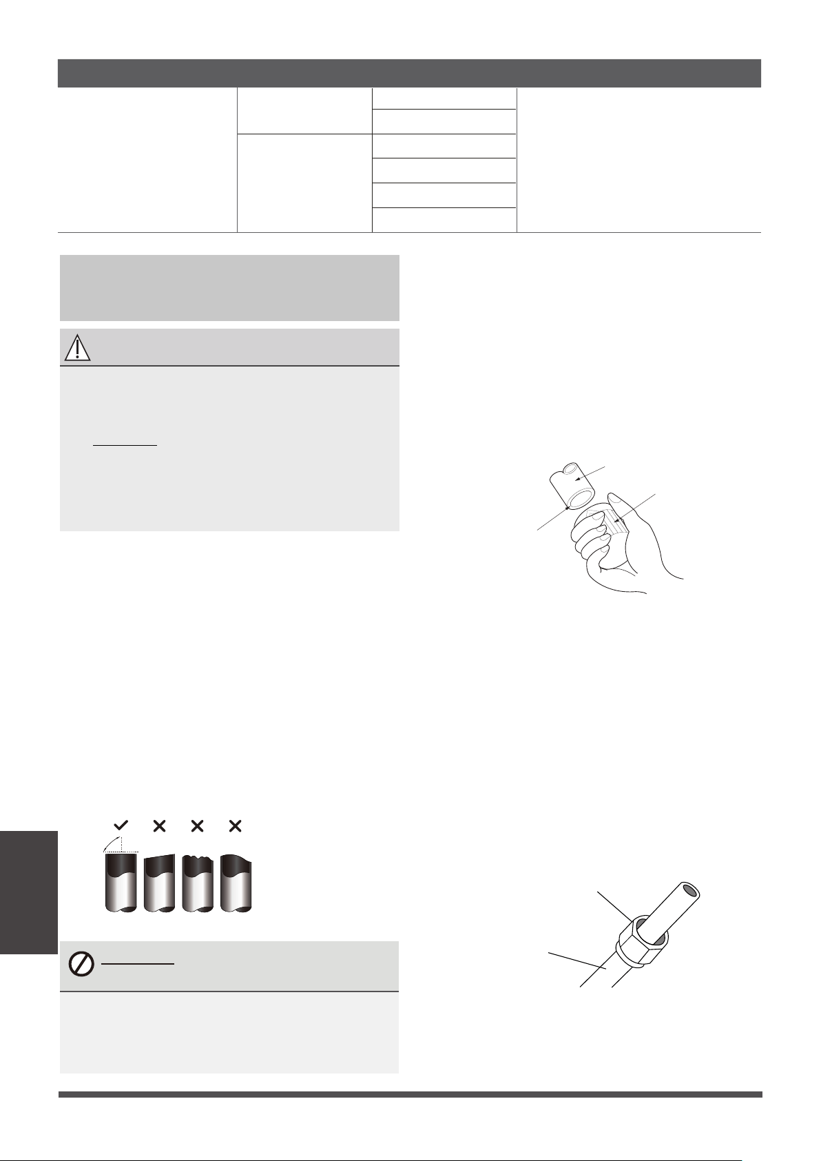
Step 1: Cut pipes
When preparing refrigerant pipes, take extra care
to cut and flare them properly. This will ensure
efficient operaon and minimize the need for future
maintenance.
1. Measure the distance between the indoor and
outdoor units.
2. Using a pipe cuer, cut the pipe a lile longer
than the measured distance.
3. Make sure that the pipe is cut at a perfect 90°
angle.
Oblique Rough Warped
90°
DO NOT DEFORM PIPE
WHILE CUTTING
Be extra careful not to damage, dent, or
deform the pipe while cung. This will
drascally reduce the heang efficiency
of the unit.
CAUTION
• The branching pipe must be installed
horizontally. An angle of more than 10° may
cause malfuncon.
• DO NOT install the connecng pipe unl
both indoor and outdoor units have been
installed.
• Insulate both the gas and liquid piping to
prevent water leakage.
Step 3: Flare pipe ends
Proper flaring is essenal to achieve an airght seal.
1.
Aer removing burrs from cut pipe, seal the ends
with PVC tape to prevent foreign materials from
entering the pipe.
2.
Sheath the pipe with insulang material.
3.
Place flare nuts on both ends of pipe. Make sure
they are facing in the right direcon, because you
can’t put them on or change their direcon aer
flaring.
Flare nut
Copper pipe
4.
Remove PVC tape from ends of pipe when ready
to perform flaring work.
2.
Using a reamer or deburring tool, remove all burrs
from the cut secon of the pipe.
Pipe
Reamer
Point down
Step 2: Remove burrs.
Burrs can affect the air-ght seal of refrigerant piping
connecon. They must be completely removed.
1.
Hold the pipe at a downward angle to prevent
burrs from falling into the pipe.
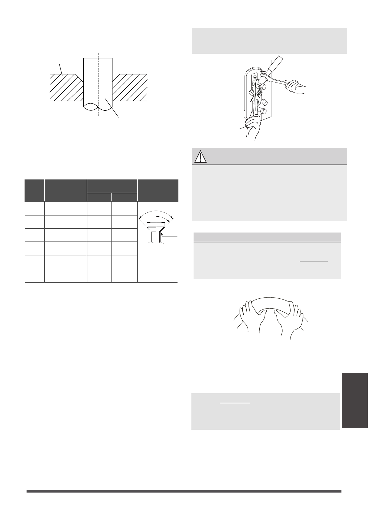
Refrigerant piping
Connection
Page 35
6.
Aer connecng the copper pipes to the indoor
unit, wrap the power cable, signal cable and the
piping together with binding tape.
NOTE: DO NOT intertwine signal cable
with other wires. While bundling these
items together, do not intertwine or cross
the signal cable with any other wiring.
Connect the copper pipes to the indoor unit first,
then connect it to the outdoor unit. You should
first connect the low-pressure pipe, then the high-
pressure pipe.
1.
When connecng the flare nuts, apply a thin
coat of refrigeraon oil to the flared ends of
the pipes.
2.
Align the center of the two pipes that you will
connect.
3.
Tighten the flare nut as ghtly as possible by
hand.
4.
Using a spanner, grip the nut on the unit tubing.
5. While firmly gripping the nut, use a torque
wrench to ghten the flare nut according to
the torque values in above table.
NOTE: Use both a spanner and a torque wrench
when connecng or disconnecng pipes to/from
the unit.
CAUTION
•
Ensure to wrap insulaon around the piping.
Direct contact with the bare piping may
result in burns or frostbite.
•
Make sure the pipe is properly connected.
Over ghtening may damage the bell mouth
and under ghtening may lead to leakage.
NOTE ON MINIMUM BEND RADIUS
Carefully bend the tubing in the middle
according to the diagram below. DO NOT
bend the tubing more than 90° or more than
3 mes.
Bend the pipe with thumb
min-radius 3.9”10cm (3.9”)
5.
Clamp flare form on the end of the pipe.
The end of the pipe must extend beyond the flare
form.
Flare form
Pipe
6.
Place flaring tool onto the form.
7.
Turn the handle of the flaring tool clockwise
unl the pipe is fully flared. Flare the pipe in
accordance with the dimensions.
PIPING EXTENSION BEYOND FLARE FORM
8. Remove the flaring tool and flare form, then
inspect the end of the pipe for cracks and even
flaring.
Pipe
gauge
Tightening
torque
Flare dimension
(A) (Unit: inch/mm)
Flare shape
Min. Max .
Ø 6.35
R0.4~0.8
45
°
±
2
90
°
±
4
A
Ø 9.52
Ø 12.7
Ø 16
Ø 19
Ø 22
65-67 N.m
(663-683 kgf.cm)
23.2/0.91 23.7/0.93
75-85N.m
(765-867 kgf.cm)
26.4/1.04 26.9/1.06
18-20 N.m
(183-204 kgf.cm)
8.4/0.33 8.7/0.34
25-26 N.m
(255-265 kgf.cm)
13.2/0.52 13.5/0.53
35-36 N.m
(357-367 kgf.cm)
16.2/0.64 16.5/0.65
45-47 N.m
(459-480 kgf.cm)
19.2/0.76 19.7/0.78
Step 4: Connect pipes

7. Thread this pipeline through the wall and
connect it to the outdoor unit.
8. Insulate all the piping, including the valves of
the outdoor unit.
9. Open the stop valves of the outdoor unit to
start the flow of the refrigerant between the
indoor and outdoor unit.
CAUTION
Check to make sure there is no refrigerant
leak aer compleng the installaon work.
If there is a refrigerant leak, venlate the area
immediately and evacuate the system (refer
to the Air Evacuaon secon of this manual).
Aer the unit is installed, Wrap the valve body
with insulaon material and make sure the valve
is sealed.
Thermal insulation
material
Page 36
Complete the indoor unit connecon pipe
assembly as shown below, use flare-to-braze
(3/4" to 7/8") adapters to connect 7/8 "Line set.
If you connect it in a way other than the one
shown in the figure, it will cause the performance
of the product to decrease.
60K Air-Handler Air Conditioners
Refrigerant Piping Connection
( for North America models)
3/4" Service valve
7/8" Line set
Flare-to-braze (3/4" to 7/8")
Refrigerant piping
Connection
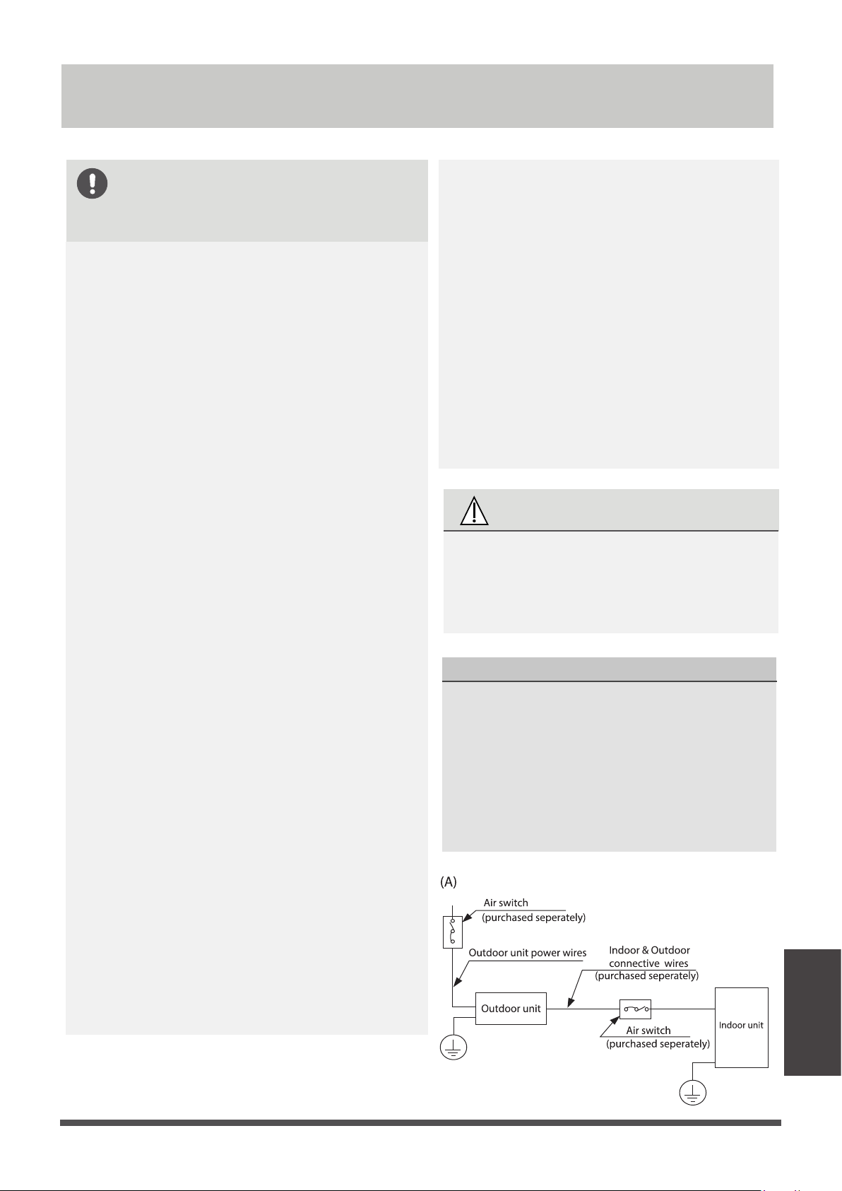
Wiring
BEFORE PERFORMING ANY
ELECTRICAL WORK, READ
THESE REGULATIONS
1. All wiring must comply with local and naonal
electrical switchs, regulaons and must be
installed by a licensed electrician.
2. All electrical connecons must be made
according to the Electrical Connecon Diagram
located on the panels of the indoor and outdoor
units.
3. If there is a serious safety issue with the power
supply, stop work immediately. Explain your
reasoning to the client, and refuse to install the
unit unl the safety issue is properly resolved.
4. Power voltage should be within 90-110% of
rated voltage. Insufficient power supply can
cause malfuncon, electrical shock, or fire.
5. If connecng power to fixed wiring, a surge
protector and main power switch should be
installed.
6. If connecng power to fixed wiring, a switch
or circuit breaker that disconnects all poles and
has a contact separaon of at least 1/8in (3mm)
must be incorporated in the fixed wiring. The
qualified technician must use an approved
circuit breaker or switch.
Do not let wires touch or rest against refrigerant
tubing, the compressor, or any moving parts
within the unit.
If the unit has an auxiliary electric heater, it must
be installed at least 1 meter (40in) away from
any combusble materials.
To avoid geng an electric shock, never touch
the electrical components soon aer the power
7. Only connect the unit to an individual branch
circuit outlet. Do not connect another
appliance to that outlet.
8.
Make sure to properly ground the air condioner.
9. Every wire must be firmly connected. Loose
wiring can cause the terminal to overheat,
resulng in product malfuncon and possible fire.
10.
11.
12.
13.
Make sure that you do not cross your
electrical wiring with your signal wiring.
This may cause distoron and
interference.
14.
The unit must be connected to the
main outlet. Normally, the power supply
must have a impedance of 32 ohms.
15.
No other equipment should be
connected to the same power circuit.
16.
Connect the outdoor wires before
connecng the indoor wires.
supply has been turned off. Aer turning off
the power, always wait 10 minutes or more
before you touch the electrical components.
WARNING
BEFORE PERFORMING ANY
ELECTRICAL OR WIRING WORK,
TURN OFF THE MAIN POWER TO
THE SYSTEM.
NOTE ON AIR SWITCH
When the maximum current of the air
condioner is more than 16A, an air switch
or leakage protecon switch with
protecve device shall be used(purchased
seperately) . When the maximum current
of the air condioner is less than 16A, the
power cord of air condioner shall be
equipped with plug (purchased seperately) .
Wiring
Page 37
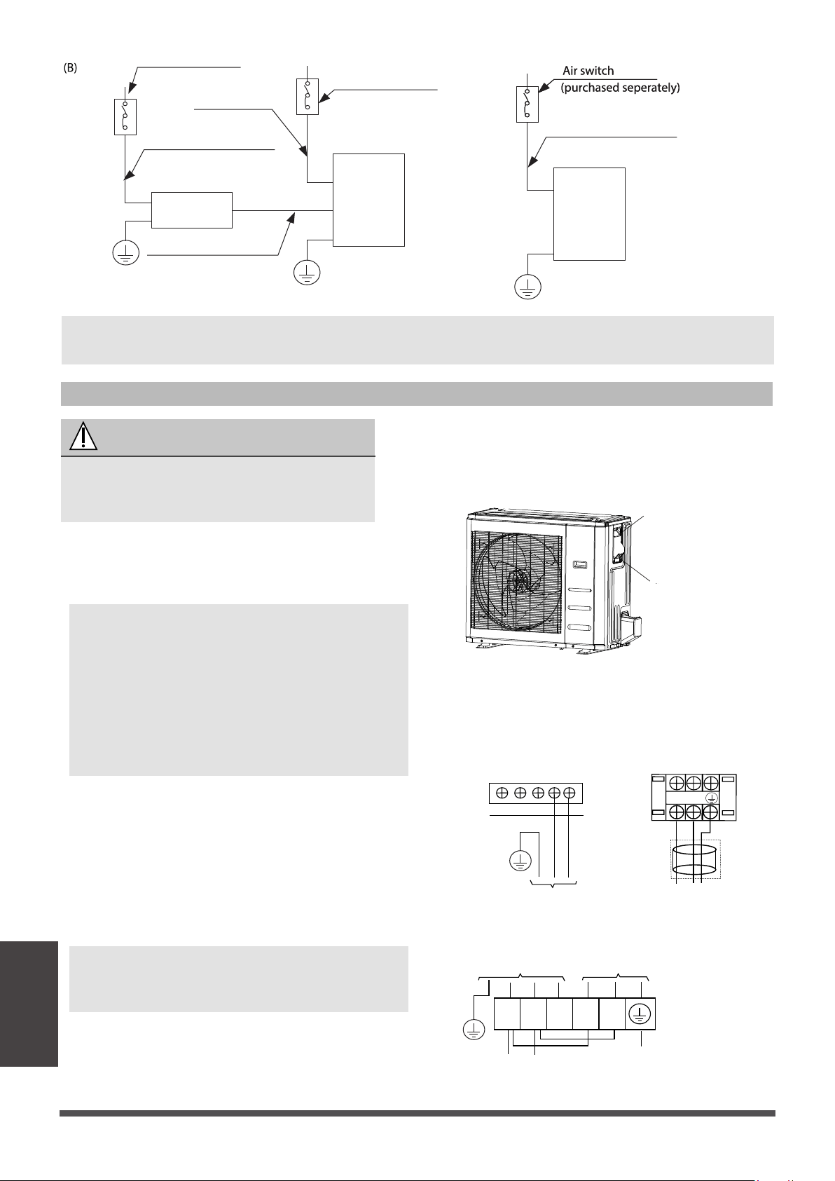
3. Connect the u-lugs to the terminals
Match the wire colors/labels with the labels
on the terminal block. Firmly screw the u-lug
of each wire to its corresponding terminal.
Using a wire crimper, crimp u-lugs on the
ends.
b. Using wire strippers, strip the rubber
jackerom both ends of the signal cable
to reveal approximately 5.9” (15cm) of
wire.
c.
Strip the insulaon from the ends.
d.
NOTE: When connecng the wires, strictly
follow the wiring diagram found inside the
electrical box cover.
NOTE:
In North America, choose the cable
type according to the local electrical switchs
and regulaons.
In North America, please choose the
right cable size according to the Minimum
Circuit Ampacity indicated on the
nameplateof the unit.
Outdoor Unit Wiring
WARNING
Before performing any electrical or wiring
work, turn off the main power to the
system.
1.
Prepare the cable for connecon
a. You must first choose the right cable
size.
NOTE: The cographs are for explanaon purpose only. Your machine may be slightly
different. The actual shape shall prevail.
2.
Remove the electric cover of the outdoor unit.
If there is no cover on the outdoor unit, take
off the bolts from the maintenance board
and remove the protecon board.
Cover
Screw
Electrical
heater
unit
Electrical heater unit power wires
Indoor unit
Outdoor unit
Air switch
(purchased seperately)
Air switch
(purchased seperately)
(purchased seperately)
Indoor unit power wires
Indoor & Outdoor
connecve wires
Outdoor unit power wires
Outdoor Unit A Outdoor Unit B
L2
L1
OPTIONAL
L1
TO POWER SOURCE
INDOOR UNIT POWER SUPPLY
TO POWER SOURCE
L2
Outdoor Unit C
1 2 3 L1 L2
Page 38
Wiring
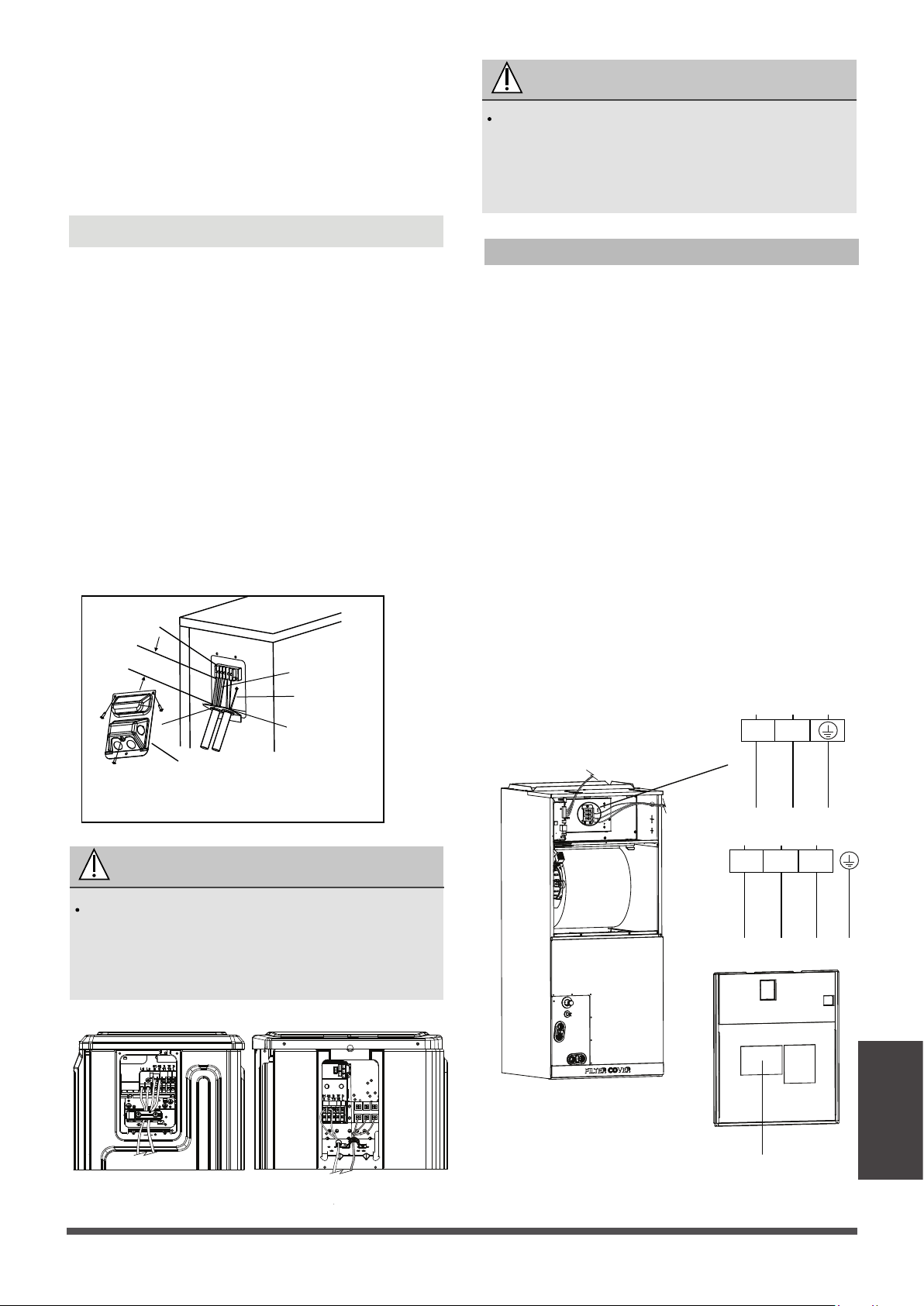
Indoor Unit Wiring
4. Clamp down the cable with the cable clamp.
5. Insulate unused wires with electrical tape.
Keep them away from any electrical or metal
parts.
6. Reinstall the cover of the electric control box.
1. Prepare the cable for connecon.
a. Using wire strippers, strip the rubber jacket
from both ends of the signal cable to reveal
about 5.9” (15cm) of the wire.
b.
Strip the insulaon from the ends of the
wires.
c. Using a wire crimper, crimp the u-lugs to
the ends of the wires.
WARNING
ISOLATE THE POWER SUPPLY LEADS AND
COMMUNICATION LEADS BY THE STRAIN
RELIF AND KEEP POWER SUPPLY LEADS
AWAY FROM COMMUNICATION LEADS.
RISK OF ELECTRIC SHOCK CAN CAUSE
INJURY OR DEATH. DISCONNECT ALL
REMOTE ELECTRIC POWER SUPPLIES
BEFORE SERVICING.
WARNING
2. Open the front panel of the indoor unit. Using
a screwdriver,remove the cover of the electric
control box on your indoor unit.
3. Thread the power cable and the signal cable
through the wire outlet.
4. Connect the u-lugs to the terminals.
Wiring diagram
1. Remove the wire cover from the unit by
loosening the 3 screws.
2. Dismount caps on the conduit panel.
3. Temperarily mount the conduit tubes(not
included) on the conduit panel.
4. Properly connect both the power supply and
low voltage lines to the corresponding
terminals on the terminal block.
5. Ground the unit in accordance with local
switchs.
6. Be sure to size each wire allowing several
inches longer than the required length for
wiring.
7. Use lock nuts to secure the conduit tubes.
In North America
G
Wire Cover
Over 1.57in.(40mm)
Terminal block
Conduit panel
Connecting cable
Power supply cord
Please select the appropriate through-hole according
to the diameter of the wire.
Outdoor Unit A Outdoor Unit B
Class2 wire
Power
wire
Match the wire colors/labels with the labels on
the terminal block. Firmly screw the u-lug of
each wire to its corresponding terminal. Refer
to the Serial Number and Wiring Diagram
located on the cover of the electric control box.
L1
TO POWER SOURCE
L2
L1
TO OUTDOOR
L2 S
Page 39
Wiring
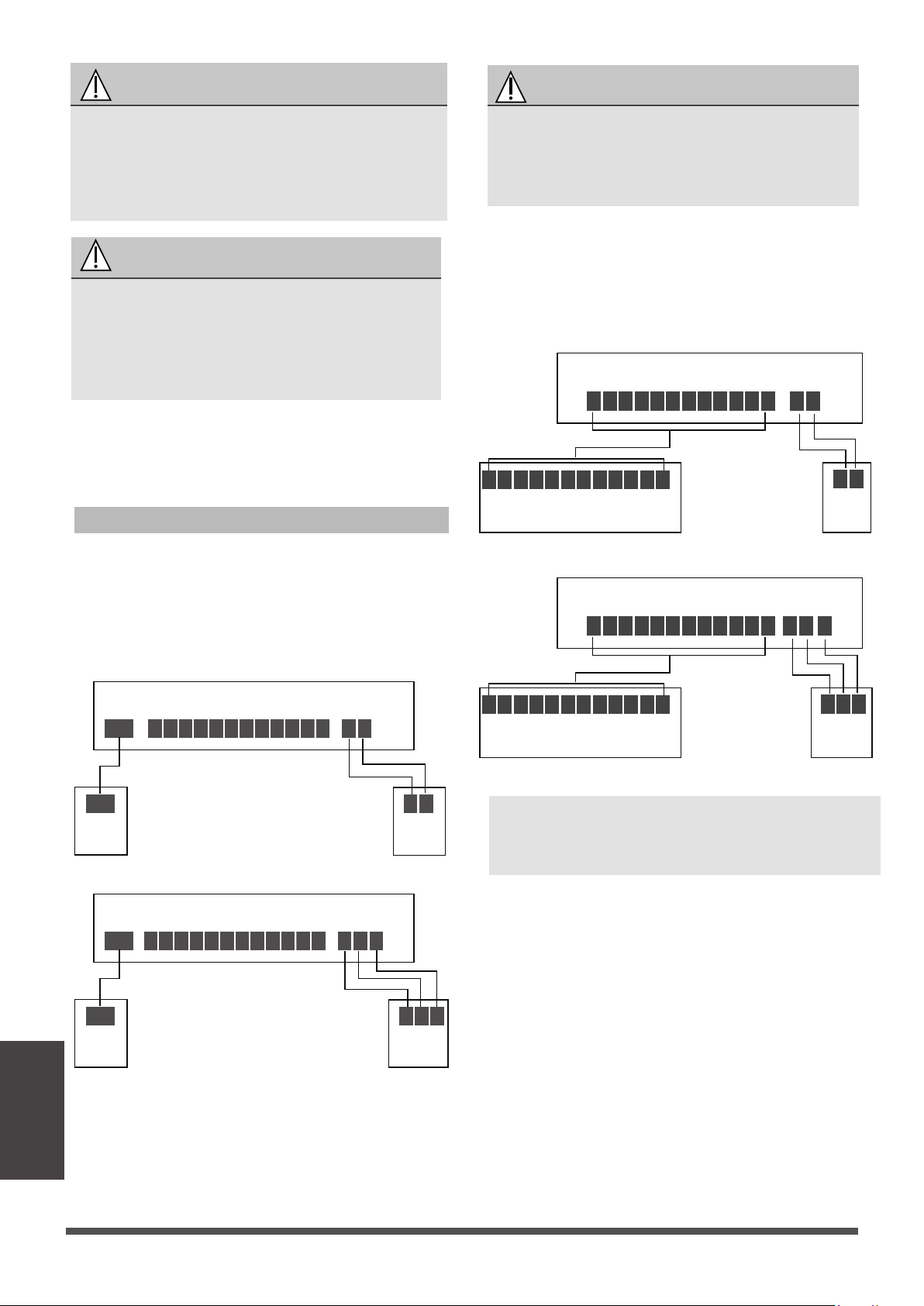
Wiring
Specific wiring method
Outdoor
Unit
Outdoor
Unit
Outdoor
Unit
Outdoor
Unit
WARNING
ISOLATE THE POWER SUPPLY AND
COMMUNICATION LEADS AS SHOWN IN
THE DIAGRAM,KEEP POWER SUPPLY
LEADS AWAY FROM COMMUNICATION
LEADS.
CAUTION
• While connecng the wires, please strictly
follow the wiring diagram.
• The refrigerant circuit can become very
hot. Keep the interconnecon cable away
from the copper tube.
5. Clamp down the cable with the cable clamp.
The cable must not be loose or pull on the
u-lugs.
6. Reaach the electric box cover.
Refer to the wiring method of internal and
external machine communicaon and wired
controller as follows:
WARNING
Please refer to the wiring nameplate for the
wiring method. Do not connect the power
cord to the communicaon line, as this may
damage the system.
R C L G Y1
Y1/Y2
B W W2 EW1 DH
S1 S2
S1 S2
Indoor unit
Wired
controller
Wired
controller
R C L G Y1
Y1/Y2
B W W2 EW1 DH
L1(1) L2(2) S(3)
L1(1) L2(2) S(3)
Indoor unit
Wired
controller
Wired
controller
Connection method A:
(A)
(B)
Page 40
NOTE: The wiring method of the thermostat and
the internal machine refers to the wiring of the
non-communicaon scheme.
To use a 24V thermostat, you need to refer to the
following wiring:
L1(1) L2(2) S(3)
L1(1) L2(2) S(3)
24V thermostat
R C G Y1 Y2 B W W2 EW1 DH L
R C G Y1 Y2 B W W2 EW1 DH L
S1 S2
S1 S2
Indoor unit
24V thermostat
R C G Y1 Y2 B W W2 EW1 DH L
R C G Y1 Y2 B W W2 EW1 DH L
Indoor unit
Connection method B:
(A)
(B)
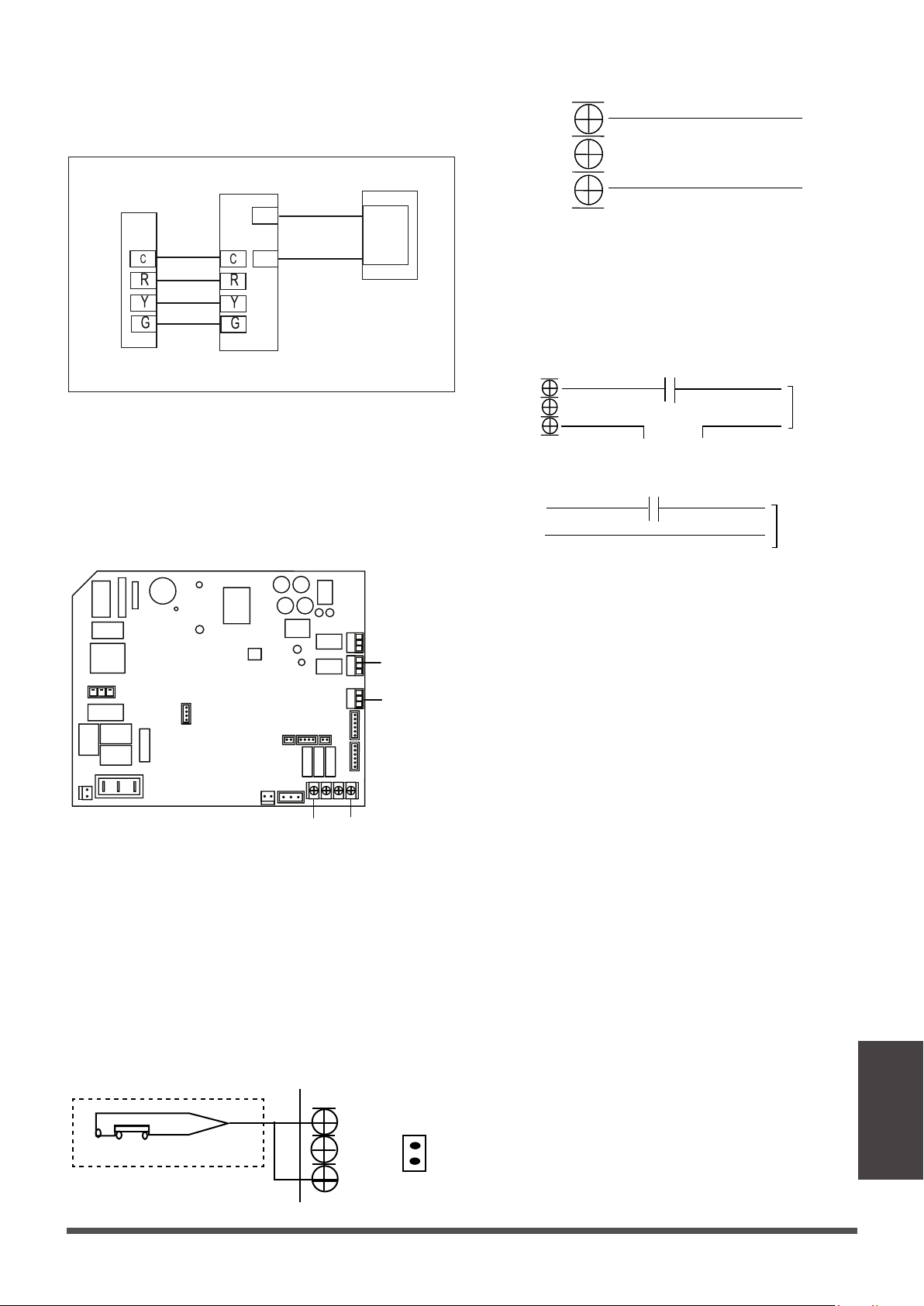
Wiring
Page 41
Connection method C:
Suggestion: It is suggested that you use was a
thermostat from Honeywell, series of non-
programmabled thermostats, including the
TH5220D.
INDOOR UNIT OUTPUT WITH 24VAC 1.5A
OUTDOOR UNITINDOOR UNIT
THERMOSTAT
BROWN
RED
RED
YELLOW
GREEN
BLACK
24V~
XT1
L1(C1)
C1
N1
N1
The unit has a liquid level detecon interface.
If you choose this funcon, you need to
purchase a liquid level switch by yourself,
connect to the CN5 interface, and remove J1.
When the water receiving pan is full, the water
level switch is disconnected, the water level switch
is reported, and the whole machine stops.
WATER LEVEL SWITCH
CN5
J1
When there is a fault in the relay to close,
otherwise the relay disconnected. This port is a
passive outlet, you need to input a voltage
signal.
Optional function wiring:
•
Humidificaon control wiring
•
The fault warning
TO
HUMIDIFIER
WORK
HUMIDISTAT
24V control signal or 208/230V power supply
CN23
TO HUMIDIFIER
HUMIDISTAT
24-VAC
G
C
CN33
ALARM
Alarm
interface
Liquid level
switch
interface
Indoor and
outdoorunit
communicaon
interface
UVLED
•
Liquid level switch interface
Passive signal port CN33, when the fan is running,
the relay is closed, it needs to be connected with
24V control signal or 208/230V power supply,
then CN33 and serial humidistat and humidifier;
Acve 24V signal, connect the G and C ports of the
control panel in series with the humidistat and
then connect the humidifier. If the thermostat or
zone controller has a HUM interface, connect the
humidifier directly to the HUM and C ports.
When the humidity drops below the set value of
the humidistat, the humidistat is turned on, and
the humidifier receives a signal or power source
and starts humidifying operaon.
Cooling and Fixed-speed Type Only System Wiring
Diagram
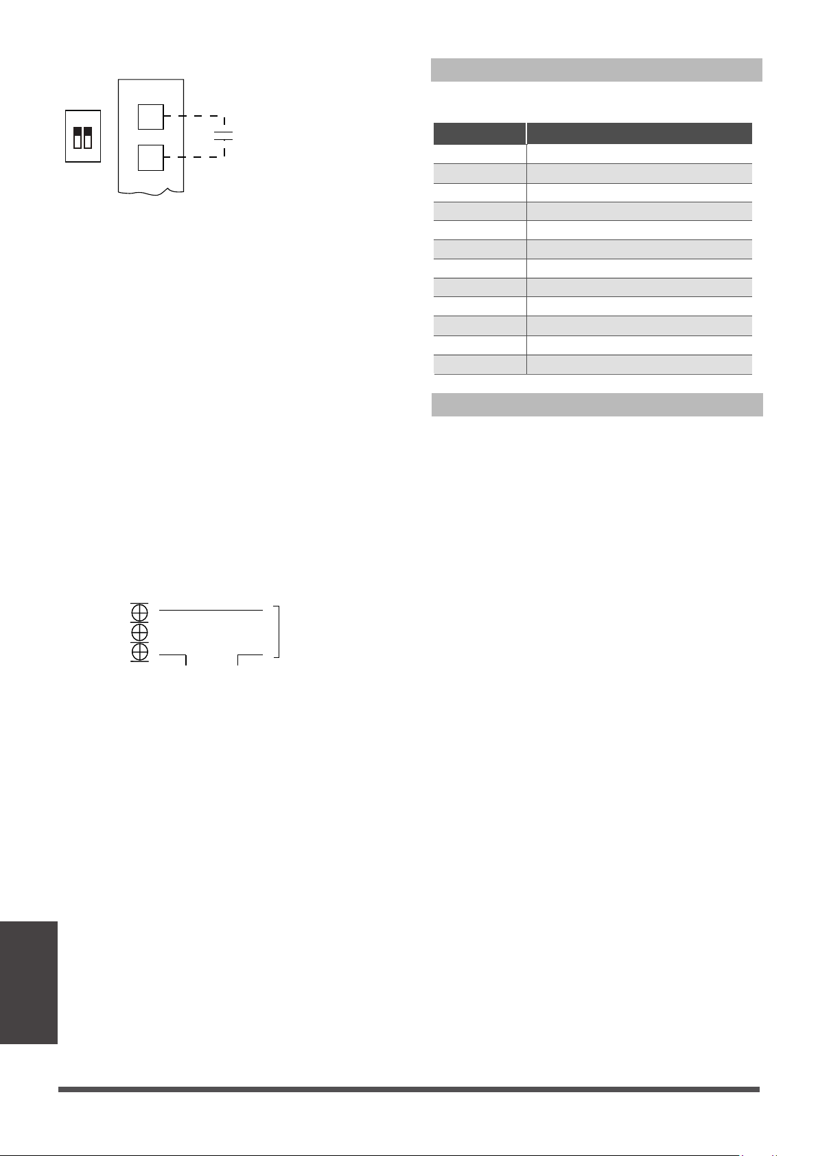
Wiring
Control Logic
LED DISPLAY
The control displays acve faults switchs on the
LED display. When the control displays the fault
switch and the LED flashes quickly, there is
something wrong with the system. Refer to the
detailed fault switchs.
When the paron control, DH is connected to
the DH port of the paron controller. When the
24V signal of DH changes to 0V, the air volume
drops to 80% of the nominal refrigeraon air
volume.
The WORK port is linked with the fan. When the
fan is running, the relay is closed; if an acve 24V
signal is required, it can be directly connected to
the G and C ports.
Indoor unit Connector
R 24V
C COM
G Fan
Y
Connector Purpose
Y/Y2
B
W
W1
W2
E/AUX
DH/DS/BK
L
First period cooling
Second period cooling
Heang(Four-way valve)
Heang operaon
Electric heang operaon 1
Electric heang operaon 2
Emergency heang
Drying regionally
Error signal
•
UV, fresh air or negave ion wiring
work
24V control signal or 208/230V power supply
UV, fresh wind or
negave ions, etc
CN23
Page 42
S4-1 DIP switch of
Perform disconnecon and short-circuit to
achieve paron, control or dehumidifcaon
Dehumidificaon control requires indirect
humidifier at DH and R. Set S4-1 as OFF.
When the humidity rises and exceeds the set
value of the humidifier, the 24V signal of DH
changes to 0V, the refrigeraon system starts the
dehumidificaon operaon, and the air volume
drops to 80% of the nominal refrigeraon air
volume.
•
Dehumidificaon control wiring
1 2
ON
S4
DH
R
HUMIDISTAT
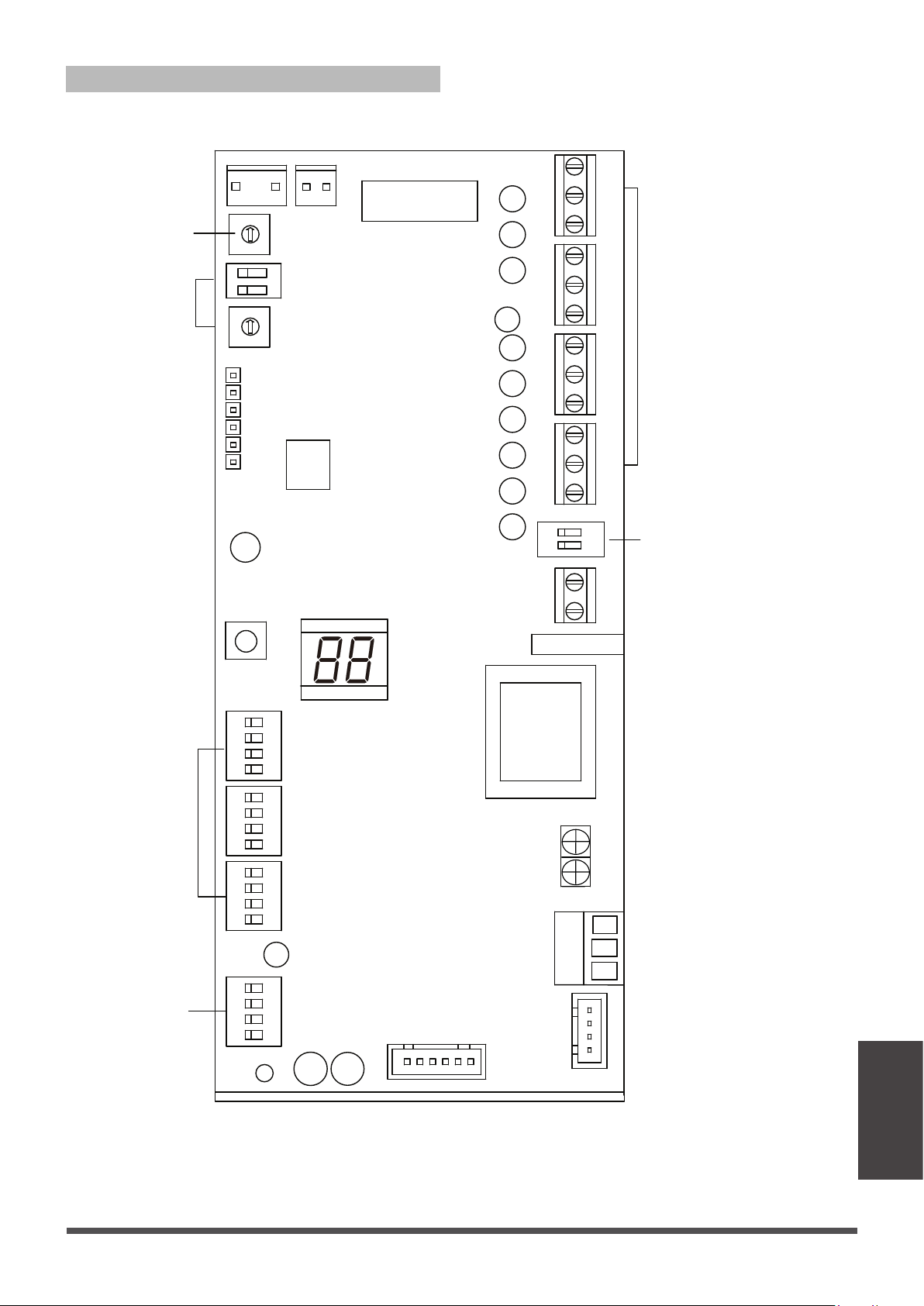
DIP Switch Definitions
24V thermostat interface
R C L
W2
E/AUX DH
SW1 SW2 SW3
S1S2S3
SW4
1 2 3 4
ON
1 2
ON
ON ON ON
1 2 3 4 1 2 3 4 1 2 3 4
B W W1
E Y X
G Y1 Y/Y2
24V control DIP switch
Funcon
DIP switch
Address
DIP switch
Funcon
DIP switch
Stac pressure
DIP switch
Wiring
Page 43

•
SW1
The dialing code mainly controls and selects the
type of unit. It is suggested to adjust under the
guidance of the engineering staff.
SW1-1: Switch communicaon mode funcon,
(ON: 24V wire controller; OFF: non-24V wire
controller, default)
SW1-2: This dial code can be used to set whether
to stop the fan when the cold air is released, OFF
stops the fan, ON does not stop the fan, default
OFF
SW1-3: Select single cold and heat pump funcons.
ON: single cooling; OFF: heang and cooling,
default
SW1-4: The dialing funcon is to select indoor and
outdoor unit or indoor unit. The default OFF means
the indoor and outdoor unit, at this me you need
to connect the outdoor unit equipped with the
AHU set. When the user uses the temperature
control to control the indoor and outdoor unit,
they need to switch the dialing code to ON, which
means the independent indoor unit; at this me,
the indoor unit module does not communicate
with the outdoor unit, and does not process the
informaon of the outdoor unit. The wire controller
cannot be used, it needs to be connected to a
24V thermostat.
•
SW2
This dial code mainly controls the opening
form of the electric auxiliary heat.
SW2-1: This dial code can control the temperature
difference when the electric heang is turned on.
OFF: 36°F/2°C, default; ON: 34°F /1°C, 3-level
temperature seng, consistent with user
thermostat seng.
Note: When E/AUX controls electric heang,
there is no temperature difference, and it starts
directly.
SW2-2, SW2-3: This two-digit dialing code can
control the delayed start of electrically-assisted
heat.
When the temperature difference is too large,
the delayed start and the delayed start me can
be selected.
Function DIP switch:
1-bit dialing, ON 36°F/2.5°C,
OFF without delay
1 bit dialing, OFF 15 minutes,
ON 30 minutes, 15 minutes by
default, delayed opening me
SW2-2
SW2-3
SW2-4: This dial code controls the allowable
opening temperature of electric heang or
compressor, OFF allows the opening temperature
of electric heang (using the set temperature of
S3 as the upper limit temperature of electric
heang), and ON the allowable opening
temperature of the compressor (using S3 as the
upper limit temperature of electric heang). The
lower limit temperature at which the compressor
can allow operaon.)
•
S3
Ambient temperature controlled by electric
heang or compressor, 0 means no temperature
protecon is turned on, 1-F is -20-8°C, and each
scale represents 2°.
SW3-1
This dialing code can set the connuous operaon
me of increasing the set temperature by 32°F~37°F
0.5°C~3°C before reaching the temperature.
The default is OFF 1.5h, ON 30min.
SW3-2
This dialing code can set Y/Y2 signal seng
temperature adjustment deviaon, ON:
34°F /1°C; OFF: 36°F/2 ° C.
SW3-3
This dialing code can set W2 signal seng
temperature adjustment deviaon, ON: 36°F/2°C;
OFF: 37°F/3 ° C.
Wiring
Page 44
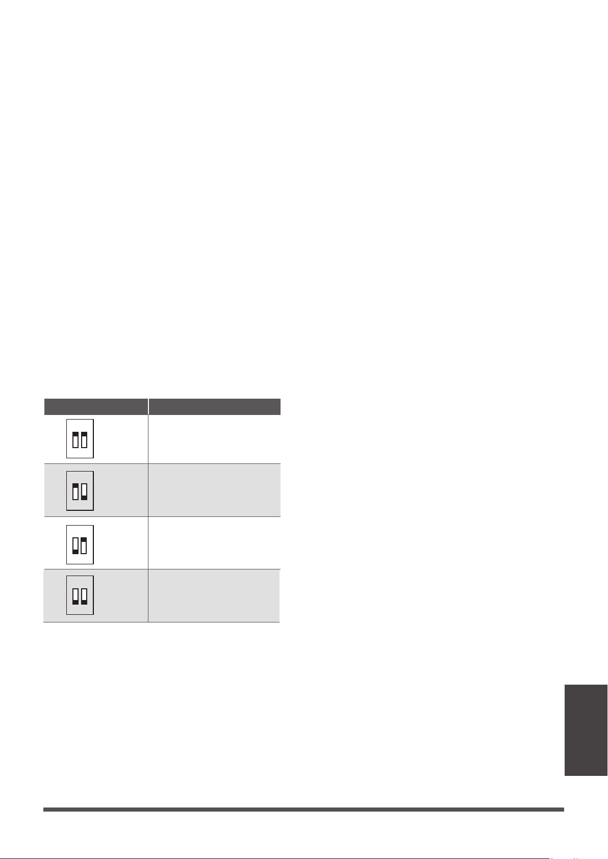
1 2
ON
1 2
ON
1 2
ON
1 2
ON
Address DIP switch: Static pressure DIP switch:
Dial code selecon Website address
Address dialing S1+S2: When the user uses the
centralized controller, the address dialing is
required.
Network address: The address silkscreen is NET
address, which is composed of a 16-bit address
rotary code S2 plus a two-digit DIP switch S1
[Set during engineering installaon, no network
funcon does not need to be set]
When S2 is 00 (the dialing code is not connected),
the network address value is the value of S2;
When S2 is 10 (corresponding to the switch of the
hardware connected to the 10K resistor), the
network address value is S2 plus 32;
When S2 is 01 (corresponding to the dial code of
the 5.1K resistor connected to the hardware is
turned on), the network address value is the
value of S2 plus 16;
When S2 is 11 (all dialing codes are on), the
network address value is the value of S2 plus 48.
Determined by dial code S2 1-10K 2-5.1K
S2 + 48
S2 + 32
S2 + 16
S2
SW4
This dialing code is only valid for 1-3. Composion
of binary code, respecvely corresponding to
different wind profile stac pressure.
000 is the default; 000/001/010/011/100/101/110/
111, with different capacies of indoor unit and
electric heang and PSC for selecon and use,
corresponding to different air volumes, see air
volume table for details.
Page 45
Wiring
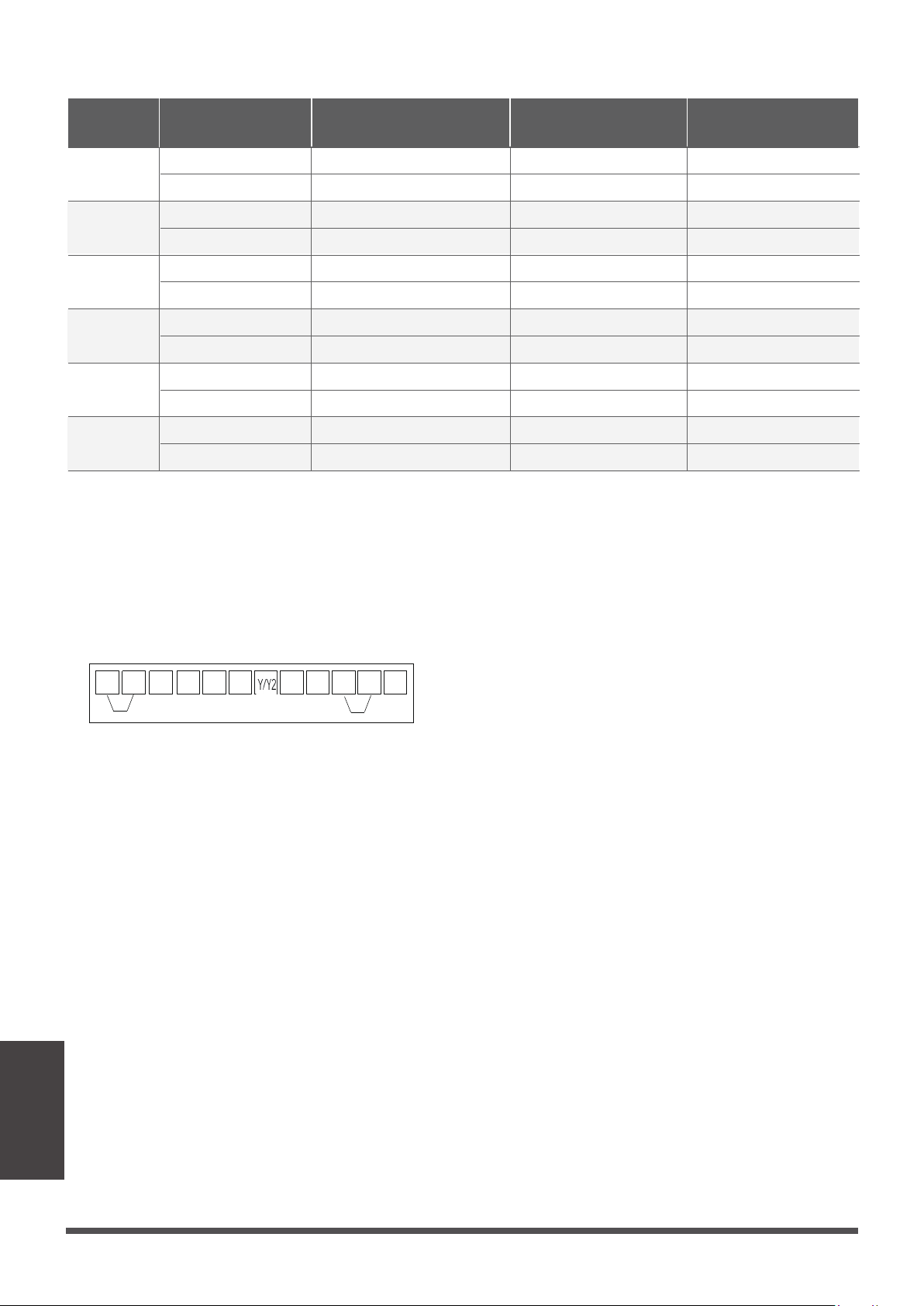
R L G B W E
C
Y1
DH
W1 W2
INDOOR UNIT
S4-2 DIP switch off
Perform disconnecon and
short-circuit to achieve
paron, control or
dehumidificaon
S4-1 DIP switch off
Disconnect and short
circuit to realize heang
segment
24V control DIP switch:
NOTE:
The wind gear DIP switch can only change the air volume when the electric heang is turned on, and the
air condioner cooling and heang air volume remains unchanged. If the DIP switch is wrong, the default
wind gear will be run.
000 gear (default)
air volume(CFM)
001 air volume(CFM) 010 air volume(CFM) 011 air volume(CFM)Model
24K
18K
30K
60K
48K
36K
660 570600630
10KW 5KW、3KW
8KW、5KW
8KW10KW 、8KW
15KW 10KW、8KW15KW 、10KW
8KW、5KW20KW 10KW、8KW15KW
8KW20KW 10KW、8KW15KW 、10KW
10KW25KW 15KW、10KW20KW 、15KW
15KW 5KW、3KW10KW、8KW15KW 、8KW
880
1100
1320
1760
2195
850
1040
1255
1675
2055
830
990
1190
1580
1920
800
930
1125
1490
1775
Air volume table
Wiring
Page 46
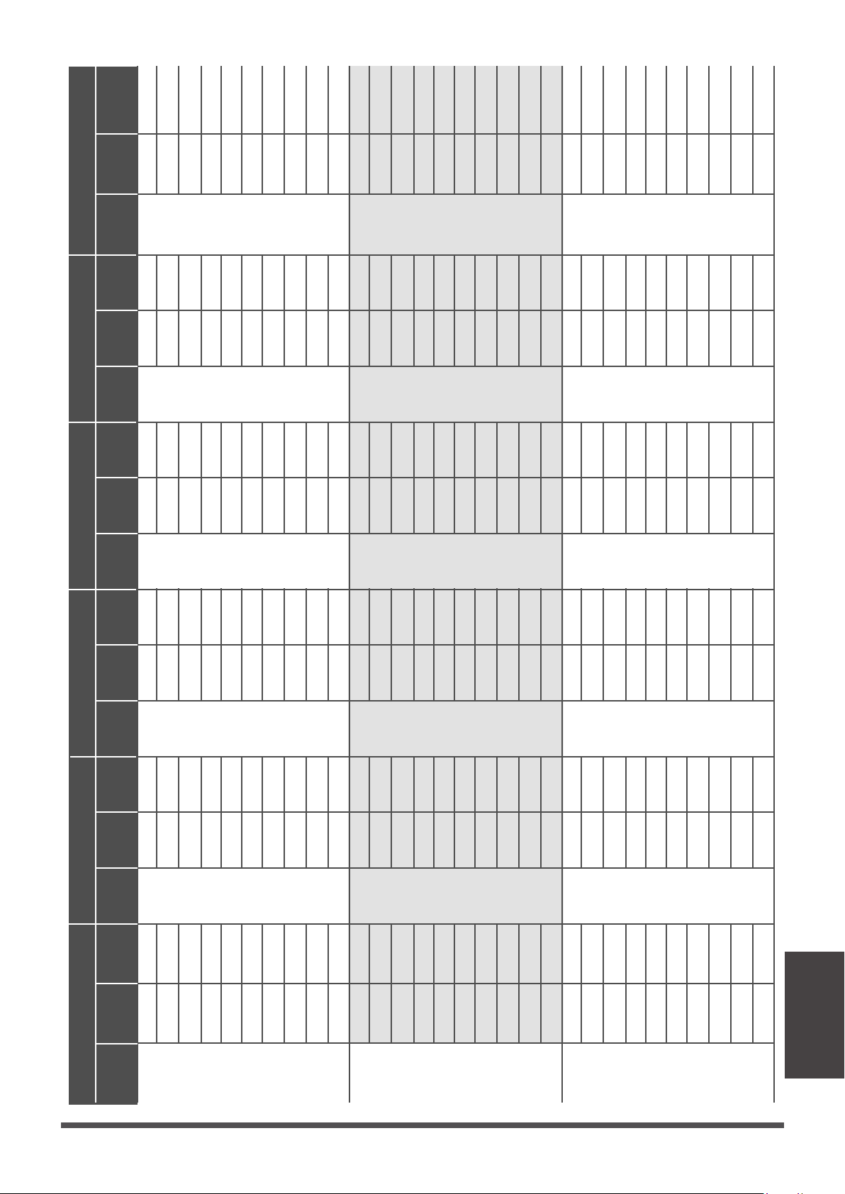
18K
24K 30K 36K 48K 60K
0
25
37
50
75
100
125
150
200
250
0
25
37
50
75
100
125
150
200
250
0
25
37
50
75
100
125
150
200
250
489
493
490
488
501
497
495
492
489
488
524
528
532
542
523
524
533
523
521
519
573
577
580
576
579
574
573
576
577
574
Low
Mid
High
Low
Mid
High
Low
Mid
High
Low
Mid
High
Low
Mid
High
Low
Mid
High
The PWM
duty cycle
Stac
pressure
Air
volume
(CFM)
The PWM
duty cycle
Stac
pressure
Air
volume
(CFM)
The PWM
duty cycle
Stac
pressure
Air
volume
(CFM)
The PWM
duty cycle
Stac
pressure
Air
volume
(CFM)
The PWM
duty cycle
Stac
pressure
Air
volume
(CFM)
The PWM
duty cycle
Stac
pressure
Air
volume
(CFM)
0
25
37
50
75
100
125
150
200
250
0
25
37
50
75
100
125
150
200
250
0
25
37
50
75
100
125
150
200
250
598
613
625
630
632
635
631
624
614
624
692
690
685
695
693
692
688
684
670
654
752
746
750
756
750
746
741
745
735
714
0
25
37
50
75
100
125
150
200
250
0
25
37
50
75
100
125
150
200
250
0
25
37
50
75
100
125
150
200
250
422
705
713
705
708
711
707
704
702
698
813
811
813
816
815
811
809
801
807
801
899
895
902
898
900
909
901
908
905
899
0
25
37
50
75
100
125
150
200
250
0
25
37
50
75
100
125
150
200
250
0
25
37
50
75
100
125
150
200
250
879
883
888
892
893
893
892
890
873
826
1010
1001
1001
1000
995
995
996
983
996
969
1137
1123
1119
1120
1112
1111
1113
1101
1094
1088
0
25
37
50
75
100
125
150
200
250
0
25
37
50
75
100
125
150
200
250
0
25
37
50
75
100
125
150
200
250
946
943
942
948
947
940
940
933
925
925
1155
1156
1154
1154
1143
1147
1149
1143
1140
1113
1325
1328
1337
1337
1330
1333
1338
1335
1321
1321
0
25
37
50
75
100
125
150
200
250
0
25
37
50
75
100
125
150
200
250
0
25
37
50
75
100
125
150
200
250
1151
1133
1136
1132
1128
1134
1130
1133
1126
1118
1367
1358
1362
1361
1360
1352
1353
1348
1340
1316
1608
1590
1586
1560
1561
1554
1549
1545
1543
1548
High, medium and low air volume parameters
Page 47
Wiring
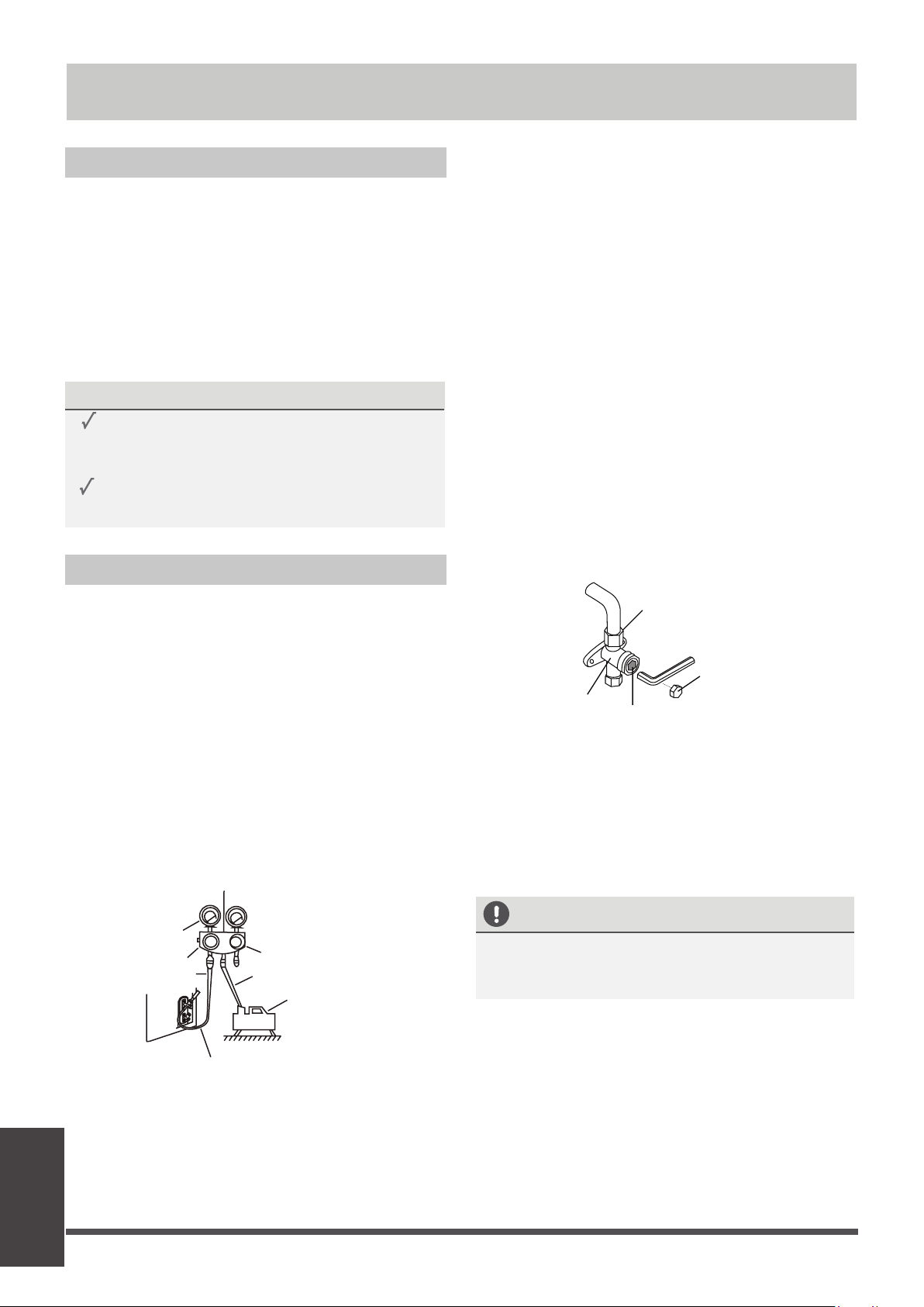
Page 48
Air Evacuation
Preparations and Precautions
Air and foreign maer in the refrigerant circuit can
cause abnormal rises in pressure, which can damage
the air condioner, reduce its efficiency, and cause
injury. Use a vacuum pump and manifold gauge to
evacuate the refrigerant circuit, removing any
non-condensable gas and moisture from the system.
Evacuaon should be performed upon inial
installaon and when unit is relocated.
BEFORE PERFORMING EVACUATION
Check to make sure the connecve pipes
between the indoor and outdoor units
are connected properly .
Check to make sure all wiring is connected
properly.
Evacuation Instructions
Manifold Gauge
Compound
gauge
-76cmHg
Low pressure
valve
High pressure
valve
Pressure hose /
Charge hose
Charge hose
V
acuum
pump
Pressure gauge
Low pressure valve
1.
Connect the charge hose of the manifold
gauge to service port on the outdoor unit’s
low pressure valve.
Connect another charge hose from the
manifold gauge to the vacuum pump.
Open the Low Pressure side of the manifold
gauge. Keep the High Pressure side closed.
Turn on the vacuum pump to evacuate the
system.
Run the vacuum for at least 15 minutes, or
unl the Compound Meter reads -76cmHG
(-10
5
Pa).
2.
3.
4.
5.
6.
Close the Low Pressure side of the manifold
gauge, and turn off the vacuum pump.
7.
Wait for 5 minutes, then check that there
has been no change in system pressure.
8.
If there is a change in system pressure, refer
to Gas Leak Check secon for informaon
on how to check for leaks. If there is no
change in system pressure, unscrew the cap
from the packed valve (high pressure valve).
9.
Insert hexagonal wrench into the packed valve
(high pressure valve) and open the valve by
turning the wrench in a 1/4 counterclockwise
turn. Listen for gas to exit the system, then
close the valve aer 5 seconds.
10.
Watch the Pressure Gauge for one minute
to make sure that there is no change in
pressure. The Pressure Gauge should read
slightly higher than atmospheric pressure.
Flare nut
Cap
valve body
valve stem
11.
Remove the charge hose from the service port.
12.
Using hexagonal wrench, fully open both the
high pressure and low pressure valves.
13.
Tighten valve caps on all three valves (service
port, high pressure, low pressure) by hand.
You may ghten it further using a torque
wrench if needed.
OPEN VALVE STEMS GENTLY
When opening valve stems, turn the hexagonal
wrench unl it hits against the stopper. Do not
try to force the valve to open further.
Air Evacuation
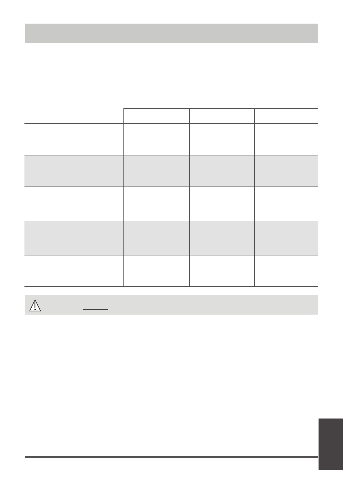
Page 49
Note on Adding Refrigerant
Some systems require addional charging depending on pipe lengths. The standard pipe length varies
according to local regulaons. For example, in North America, the standard pipe length is 25’ (7.5m).
In other areas, the standard pipe length is 16‘5m (16‘). The refrigerant should be charged from the service
port
on the outdoor unit’s low pressure valve.
The addional refrigerant to be charged can be
calculated using the following formula:
CAUTION
DO NOT mix refrigerant types.
Liquid Side Diameter
R32 :
(Total pipe length -
standard pipe length)x
12g(0.13oZ)/m()
(Total pipe length -
standard pipe length)x
24g(0.26oZ)/m()
(Total pipe length -
standard pipe length)x
40g(0.42oZ)/m()
φ1/4”(6.35) φ3/8”(9.52) φ1/2”(12.7)
R22
(orifice tube in the indoor unit):
(Total pipe length -
standard pipe length)x
30g (0.32oZ)/m()
(Total pipe length -
standard pipe length)x
65g(0.69oZ)/m()
(Total pipe length -
standard pipe length)x
115g(1.23oZ)/m()
R22
(orifice tube in the outdoor unit):
(Total pipe length -
standard pipe length)
x15g(0.16oZ)/m()
(Total pipe length -
standard pipe length)
x30(0.32oZ)/m()
(Total pipe length -
standard pipe length)
x60g(0.64oZ)/m()
(Total pipe length -
standard pipe length)
x65g(0.69oZ)/m()
R410A:
(orifice tube in the indoor unit):
(Total pipe length -
standard pipe length)
x30g(0.32oZ)/m()
(Total pipe length -
standard pipe length)
x65g(0.69oZ)/m()
(Total pipe length -
standard pipe length)
x115g(1.23oZ)/m()
R410A:
(orifice tube in the outdoor unit):
(Total pipe length -
standard pipe length)
x15g(0.16oZ)/m()
(Total pipe length -
standard pipe length)
x30g(0.32oZ)/m()
Air Evacuation
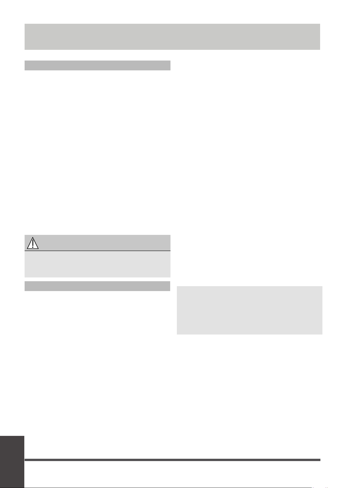
Test Run
Test Run
Before Test Run
A test run must be performed aer the enre
system has been completely installed. Confirm
the following points before performing the test:
a) Indoor and outdoor units are properly
installed.
b) Piping and wiring are properly connected.
c)
No obstacles near the inlet and outlet of
the unit that might cause poor performance
or product malfuncon.
d) Refrigeraon system does not leak.
e) Drainage system is unimpeded and
draining to a safe locaon.
f) Heang insulaon is properly installed.
g) Grounding wires are properly connected.
h) Length of the piping and addional
refrigerant stow capacity have been
recorded.
i) Power voltage is the correct voltage
for the air condioner.
CAUTION
Failure to perform the test run may result in
unit damage, property damage, or personal
injury.
Test Run Instructions
1. Open both the liquid and gas stop valves.
2. Turn on the main power switch and allow the
unit to warm up.
3. Set the air condioner to COOL mode.
4. For the Indoor Unit
a.
b.
c.
Double check to see if the room
temperature is being registered correctly.
d.
Ensure the manual buons on the indoor
unit works properly.
Check to see that the drainage system is
unimpeded and draining smoothly.
Ensure there is no vibraon or abnormal
noise during operaon.
5. For the Outdoor Unit
a. Check to see if the refrigeraon system is
leaking.
b. Make sure there is no vibraon or
abnormal noise during operaon.
c. Ensure the wind, noise, and water
generated by the unit do not disturb your
neighbors or pose a safety hazard.
6. Drainage Test
a. Ensure the drainpipe flows smoothly. New
buildings should perform this test before
finishing the ceiling.
b. Remove the test cover. Add 2,000ml of
water to the tank through the aached
tube.
c. Turn on the main power switch and run
the air condioner in COOL mode.
d. Listen to the sound of the drain pump to
see if it makes any unusual noises.
e. Check to see that the water is discharged.
It may take up to one minute before the
unit begins to drain depending on the
drainpipe.
f. Make sure that there are no leaks in any of
the piping.
g. Stop the air condioner. Turn off the main
power switch and reinstall the test cover.
NOTE: If the unit malfuncons or does not
operate according to your expectaons,
please refer to the Troubleshoong secon
of the Owner’s Manual before calling
customer service.
Page 50
LIMITED WARRANTY STATEMENT
PRODUCT REGISTRATION:
Model No.: ______________________________________________________________________________________________
Serial No.: _______________________________________________________ Date of Installation: ______________________
Owner Name: ____________________________________________________________________________________________
Address of Installation:_____________________________________________________________________________________
Installing Contractor: __________________________________________________________________________
____________
Address: ________________________________________________________________________________________
Phone No. / E-mail: _______________________________________________________________________________
Place Of Purchase:
________________________________________________________________________________________
Date of Purchase:
_______________________________________________________________________________
www.cooperandhunter.us
Visit our website for:
• Product Information
• Warranty Registration
• Installation Manual
• User Guides and more
www.cooperandhunter.us
Visit our YouTube Channel for:
• Instructional Videos
• Tutorials and How Tos
• Product Introductions
• Advertisement and more
www.youtube.com/
cooperandhunterusa
The warranty should be registered on our website www.cooperandhunter.us or by submitting the card below within
60 days of installation. The warranty is only valid when unit is installed by a licensed HVAC technician and registered
within 60 days of installation date. If you decide to submit card, send by e-mail to [email protected]
License Number: __________________________________________________________________________
____________
AIR HANDLER
For warranty service or repair:
Contact your installing contractor
C&H distributor (hereinafter “Company”) warrants this product against failure due to defect in materials or workmanship
under normal use and maintenance as follows. All warranty periods begin on the date of original installation.
if the date cannot be veried, the warranty period beginsone hundred twenty (120) days from date of manufacture.
Damage resulting from failure to use, install or maintain the product in a manner consistent with our/manufacturer’s
recommendations shall render the warranty void. Cooper&Hunter, at its option, may request a report from a qualied
technician prior to honoring a warranty claim. if a part fails due to defect duringthe applicable warranty period.
Company will provide a new or remanufactured part, at Company’s option, to replace the failed defective part at no
charge for the part. This limited warranty is subject to all provisions, conditions, limitations and exclusions listed below.
• A limited warranty covers 5 yrs for commercial applications and 10 yrs for residential applications
• Limited warranty covers 1 year for Cooper&Hunter accessories

•
under applicable local and state law in accordance with all applicable building codes and permits; C&H installation and
operation instructions and good trade practices.
• Warranty applies only to products remaining in their original installation location.
• Defective parts must be returned to the distributor through a registered servicing dealer for credit.
LIMITATIONS OF WARRANTIES: ALL IMPLIED WARRANTIES AND/OR CONDITIONS (INCLUDING IMPLIED WARRANTIES OR
CONDITIONS OF MERCHANTABILITY AND FITNESS FOR A PARTICULAR USE OR PURPOSE) ARE LIMITED TO THE DURATION
OF THIS LIMITED WARRANTY. SOME STATES OR PROVINCES DO NOT ALLOW LIMITATIONS ON HOW LONG AN IMPLIED
WARRANTY OR CONDITION LASTS, SO THE ABOVE MAY NOT APPLY TO YOU. THE EXPRESS WARRANTIES MADE IN THIS
WARRANTY ARE EXCLUSIVE AND MAY NOT BE ALTERED, ENLARGED, OR CHANGED BY ANY DISTRIBUTOR, DEALER, OR
OTHER PERSON, WHATSOEVER.
THIS WARRANTY DOES NOT COVER:
1. Labor or other costs incurred for diagnosing, repairing, removing, installing, shipping, servicing, or handling of
defective parts, replacement parts, or new units.
2. Product cleaning required prior to warranty service and repair.
3.
4. Failure, damage, or repairs due to faulty installation, misapplication, abuse, improper servicing, unauthorized
alteration,
or improper operation.
5. Failure to sta
rt due to voltage conditions, blown fuses, open circuit breakers, or damages due to the inadequacy or
interruption of electrical service.
6.
conditions beyond the control of Company.
7. Failure or damage of coils or piping due to corrosion on installations within one (1) mile of a sea coast or a corrosive
body.
8. Parts not supplied or designated by Company, or damages resulting from their use.
9. Products installed outside the continental USA and Canada.
10. Electricity or fuel costs, or increases in electricity or fuel costs for any reason whatsoever, including additional or
unusual use of supplemental electric heat.
11.
12. Shipping damage or damage as a result of transporting the unit.
13. Accessories such as condensate pumps, line sets, and so forth.
14. Any special, indirect, or consequential property or commercial damage of any nature whatsoever. Some states or
provinces do not allow the exclusion of incidental or consequential damages, so the above limitation may not apply to
you.
to province.
Consult with the sales agency or manufacturer for details.
• Warranty applies only to air handler units which are installed and used exclusively with Cooper&Hunter equipment
and accessories.
Design and specications are subject to change without notice for product improvement.
Normal maintenance as outlined in the installation and servicing instructions or user’s manual, including lter
cleaning and/or replacement and lubrication
Failure or damage due to oods, winds, res, lightning, accidents, corrosive enviorments (rust, etc.) or other
Any cost to replace, rell, or dispose of refrigerant, including the cost of refridgerant
Limited warranty applies only to systems that are properly installed by a state certied or licensed HVAC contractor

QS003UI-AHU
16123100000368
20211129
The design and specifications are subject to change without prior notice for
product improvement. Consult with the sales agency or manufacturer for details.
Any updates to the manual will be uploaded to the service website, please check
for the latest version.
Normal maintenance as outlined in the installation and servicing instructions or user’s manual, including lter
cleaning and/or replacement and lubrication