Loading ...
Loading ...
• Use recommended accessories (refer to page 15).
Use of improper accessories may cause risk of
injury to persons.
• Handle workpiece correctly. Protect hands from pos-
sible injury.
• Turn machine off if it jams. Blade jams when it digs
too deeply into workpiece. (Motor force keeps it
stuck in the work.)
• Always keep drive, cutterhead and blade guards in
place and in proper operating condition.
• Feed work into blade or cutter against direction of
rotation.
CAUTION: Think safety! Safety is a combination of
operator common sense and alertness at all times
when tool is being used.
WARNING: Do not attempt to operate tool until it is
completely assembled according to the instructions.
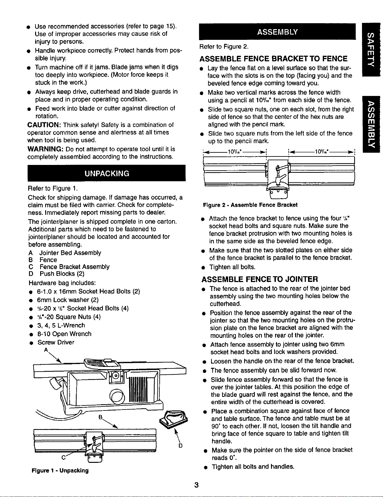
Refer to Figure 1.
Check for shipping damage. If damage has occurred, a
claim must be filed with carrier. Check for complete-
ness. Immediately report missing parts to dealer.
The jointer/planer is shipped complete in one carton.
Additional parts which need to be fastened to
jointer/planer should be located and accounted for
before assembling.
A Jointer Bed Assembly
B Fence
C Fence Bracket Assembly
D Push Blocks (2)
Hardware bag includes:
• 6-1.0 x 16mm Socket Head Bolts (2)
• 6mm Lock washer (2)
• '/,-20 x '/2"Socket Head Bolts (4)
• V,'-2O Square Nuts (4)
• 3, 4, 5 L-Wrench
• 8-10 Open Wrench
• Screw Driver
A
Figure I - Unpacking
Refer to Figure 2.
ASSEMBLE FENCE BRACKETTO FENCE
• Lay the fence flat on a level surface so that the sur-
face with the slots is on the top (facing you) and the
beveled fence edge coming toward you.
• Make two vertical marks across the fence width
using a pencil at 103/,6"from each side of the fence.
• Slide two square nuts, one on each slot, from the right
side of fence so that the center of the hex nuts are
aligned with the pencil mark.
• Slide two square nuts from the left side of the fence
up to the pencil mark.
Figure 2 - Assemble Fence Bracket
• Attach the fence bracket to fence using the four '/,"
socket head bolts and square nuts. Make sure the
fence bracket protrusion with two mounting holes is
in the same side as the beveled fence edge.
• Make sure that the two slotted plates on either side
of the fence bracket is parallel to the fence bracket.
• Tighten all bolts.
ASSEMBLE FENCE TO JOINTER
• The fence is attached to the rear of the jointer bed
assembly using the two mounting holes below the
cutterhead.
• Position the fence assembly against the rear of the
jointer so that the two mounting holes on the protru-
sion plate on the fence bracket are aligned with the
mounting holes on the rear of the jointer.
• Attach fence assembly to jointer using two 6mm
socket head bolts and lock washers provided.
• Loosen the handle on the rear of the fence bracket.
• The fence assembly can be slid forward now.
• Slide fence assembly forward so that the fence is
over the jointer tables. At this position the edge of
the blade guard will rest against the fence, and the
entire width of the cutterhead is covered.
• Place a combination square against face of fence
and table surface. The fence and table must be at
90" to each other. If not, loosen the tilt handle and
bring face of fence square to table and tighten tilt
handle.
• Make sure the pointer on the side of fence bracket
reads 0°.
• Tighten all bolts and handles.
3
Loading ...
Loading ...
Loading ...