IMPORTANT MANUAL Do Not Throw Away
Operator's
Manual
@
Model No.
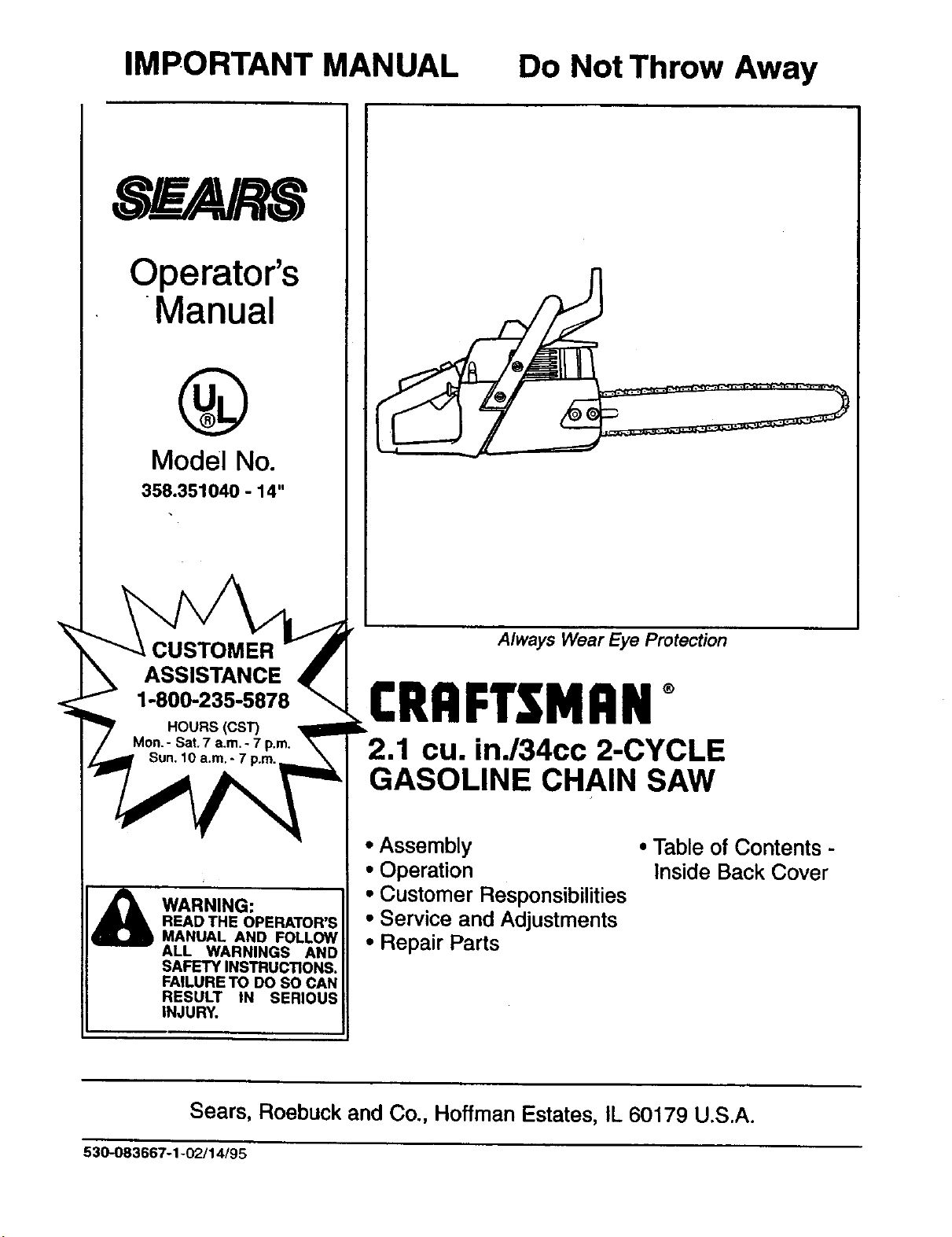
358.351040 - 14"
CUSTOMER
ASSISTANCE
1-800-235-5878
WARNING:
READ THE OPERATOR'S
MANUAL AND FOLLOW
ALL WARNINGS AND
SAFETY INSTRUCTIONS.
FAILURE TO DO SO CAN
RESULT iN SERIOUS
iNJURY.
Always Wear Eye Protection
R#°
2.1 cu. in./34cc 2-CYCLE
GASOLINE CHAIN SAW
• Assembly • Table of Contents -
• Operation Inside Back Cover
• Customer Responsibilities
• Service and Adjustments
• Repair Parts
Sears, Roebuck and Co., Hoffman Estates, IL 60179 U.S.A.
530-083667-1-02/14/95

SAFETY RULES
WARNING:
ALWAYS DISCONNECT SPARK PLUG WIRE AND PLACE WIRE WHERE IT CANNOT CONTACT SPARK
PLUG TO PREVENT ACCIDENTAL STARTING WHEN SE'n'ING UP,TRANSPORTING, ADJUSTING OR
MAKING REPAIRS EXCEPT CARBURETOR ADJUSTMENTS.
BECAUSE A CHAIN SAW IS A HIGH-SPEED WOOD-CUt"rING TOOL, SPECIAL SAFETY
PRECAUTIONS MUST BE OBSERVED TO REDUCE THE RISK OF ACCIDENTS. CARELESS OR
IMPROPER USE OFTHIS TOOL CAN CAUSE SERIOUS INJURY.
Do not handle or operate a chain saw when you am
Headng Safety Hat fatigued, III, or upset, or If you have taken alcohol,
Protection_ | _1 drugs, or medication. You mustbe in goodphysical
S_t_!?ng..__ ii_mi_ _ conditionand mentallyalert. Chain saw workisstrenu-
• ous. Ifyouhaveanyconditionthatmightbeaggravated
bystrenuouswork,checkwithyourdoctorbeforeoper-
atinga chain saw.
Do not attempt to use your chain saw during bad
ores weather conditionssuchas strongwind, rain,snow,ice,
Carefully plan your sawing operatlon In advance.
Do notstartcuttinguntilyou havea clear workarea, se-
cure footing,and, ifyou are fellingtrees, a plannedre-
Safety _..U,....'!i}; afetyChaps treat path.
Do not operate a chain saw that Is damaged,
Impropedy adjusted, or not completely and
securely assembled. Always replace the
"_N handgusrd Immediately If It becomes damaged,
broken, or Is other wise removed.
Figure I
KNOW YOUR SAW
• Read your operator's manual carefully until you
completelyunderstand and can followall safety rules,
precautions,and operatinginstructionsbeforeattempt-
ingto operate the unit.
Reetrlct the use of your saw to adult users who un-
derstandand can follow safetymiss, precautions,and
operatingInstructionsfoundinthis manual.
PLAN AHEAD
• Wear protective gear. Figure 1. Always use steel-
toed safety footwear with non-slip soles; snug-fitting
clothing;heavy-duty, non-slip gloves; eye protection
suchas non-fogging, ventedgogglesorfaca screen;an
approved safety hard hat; and sound barriers---ear
plugsormufflars toprotectyourheadng. Regularusers
should have hearing checked regularly as chain saw
noisecan damage hearing.
i eep all parts of your body away from the chain
when the engine Is running.
Keep children, bystanders, end anlmal# • minimum
of 30 feet (10 Meters) away from the work ares. Do
not allowother people or animals to be near the chain
sew when starting or operatingthechain saw.
• Keep the handles dry, clean, and free of oll or fuel
mixture.
• With the engine stopped, hand carry the chain saw
with the muffler away from your body, andtheguide
bar and chain to the rear, preferably covered with e
scabbard.
FUEL HANDLING
• EIImlneta all sources of sparks or flames in the ar-
eas where fuel Is mixed, poured, or stored. There
shouldbe no smoking,open flames,or workthatcould
cause sparks. Altow engine tocoolbefore refueling.
• Mix and pour fuel In an outdoor area on bareground;
storefuelina cool,dry,wellventilatedplace;andusean
approved, marked containerforall fuel purposes.
• Wipe up ell fuel spills before starting saw.
• Move at least 10feet (3 meters) from the fuelingsite
before starting the engine.
• Do not smoke while handling fuel or while operat-
ing the saw.
• Turn the engine off end let your saw cool in a non-
combustible area, noton dryleaves, straw,paper,etc.
Slowlyremove fuel cap and refuelunit•
• Storetheunitandfuelinanarea where fuelvaporscan-
not reach sparks or open flames from water heaters,
eleotdcmotorsor switches,fumacas, etc.
I SAFETY NOTICE I
Exposure to vibrations through prolonged use of gasoline powered hand tools could cause blood vessel or nerve damage in the I
f!ngers, hands, and joints of people prone to circulation disorders or abnormal swellings. Prolonged use in cold weather has been I
linked to blood vessel damage in otherwise healthy people. If symptoms occur such as numbness pain loss of strength change I
in skin color or texture, or loss of feeling in the fingers, hands or joints discontinue the use of this tool and seek medical attention. |
An anti-vibration system does not guarantee the avoidance.of these problems. Users who operate power tools on a continual and J
regular basis must monitor closely their physical condition and the condition of this unit. J
LOOK FOR THIS SYMBOL TO POINT OUT IMPORTANT SAFETY PRECAUTIONS.
IT MEANS- ATI'ENTIONIll BECOME ALERTlll YOUR SAFETY IS INVOLVED.
-2-

SAFETY RULES
OPERATE YOUR SAW SAFELY
i o not operate a chain saw with one hand, Serious
Injurytothe operator, helpers, byst._ders or any co.m-
binationofthese persona may resultfrom one-nanoea
operation.A chainsaw isintendedfortwo-handeduse.
Operate the chain saw only in well-ventilated out.
door areas.
Do not operate saw from • ladder or In a tree, unless
specifica|lytrained to do so.
Position ell parta of your body to the left of cut aria
away from the chain when the engine Is running.
Cut wood only. Do not useyour saw ro pry or ShOVe
away limbs, roots,or otherobjects,
• Make sure the chain will not make contact with any
object while starting the engine. Nevertrytostartthe
saw when theguide bar Is In a cutor ken.
i se extreme caution when cutting small size brush
and saplings. Slender matedal can catchthe chain
and be whippedtowardyou or pull youoffbalance,
Be alert for springbeek when cuttinga limbthat is un-
der tension soyou willnotbe struckbythe limborsaw
when the tension in thewood fibersisreleased.
• Do not put pressure on the saw etthe and of • cut.
Applyingpressurecan causeyou to lose controlwhen
the cut,iscompleted.
• Stop the engine before setting the saw down.
• Keep fuel end oll caps, screws, end fasteners ee-
curely tightened.
MAINTAIN YOUR SAW IN GOOD WORKING
ORDER
Haveall chain saw service performed byyour Sears
Service Center withtheexceptionofthe itemslistedin
themaintenancesectionofthismanual. Forexample,if
impropertoolsare used to removeor holdtheflywheel
when servicing the clutch,structuraldamage tothe fly-
wheel can occurand causethe flywheel to burst.
• Make certain the chain stops moving when the
throttle trigger is released. For correction,refer to
"CarburetorAdjustments."
• Stop the saw If the chain strikes a foreign object.
Inspectunitand repairor replaceparts as necessary.
• Dleoonnect the spark plugbefore penonnmg any
maintenance exceptfor carburetoradjustments.
Never modifyyour saw In any way. Use onlyattach-
ments supplied or specifically recommended by the
/_. manufacturer.
"TRANSPORTING AND STORAGE
Stop the unitbeforetransporting.
Allowenginetocool,covertheguide barand chain,and
secure the unit before storingor transporting in a ve-
hicle.
• Emptyfuel tank beforestoringor transportingthe unit.
Use upany fuel leftinthe carburetorby startingthe en-
gine and leffingthe engine rununtil itstops.
• Store unitandfuel inan area where fuel vaporscannot
roach sparksor openflamesfrom water heaters,elec-
tric motorsor switches, furnaces, etc.
• Store unitsothe chainsannot ascidentally cause injury.
• Store the unitout ofthe reach of children.
i i
GUARD AGAINST KICKBACK - Kickback is a dangerous reaction that can lead to serious injury.
KICKBACK WARNING
KICKBACK CAN OCCUR WHEN THE
MOVING CHAIN CONTACTS AN
OBJECT AT THE UPPER PORTION OF
THE TIP OF THE GUIDE EAR OR WHEN
THE WOOD CLOSES IN AND PINCHES
THE CHAIN IN THE CUT. CONTACT AT
THE UPPER PORTION OF THE TIP OF
THE GUIDE BAR CAN CAUSE THE
CHAIN TO DIG INTO THE OBJECT,
WHICH STOPS THE CHAIN FOR AN
INSTANT. THE RESULT ISA LIGHTNING
FAST, REVERSE REACTION WHICH
KICKS THE GUIDE BAR UP AND BACK
TOWARD THE OPERATOR. IF THE
CHAIN IS PINCHED ALONG THE TOP
OF THE GUIDE BAR, THE GUIDE BAR
CAN BE DRIVEN RAPIDLY BACK
TOWARD THE OPERATOR. EITHER OF
THESE REACTIONS CAN CAUSE LOSS
OF SAW CONTROL WHICH CAN
RESULT IN SERIOUS INJURY. DO NOT
RELY ONLY ON THE SAFETY DEVICES
PROVIDED WITH YOUR SAW. AS A
CHAIN SAW USER, YOU MUST TAKE
SPECIAL SAFETY PRECAUTIONS TO
HELP KEEP YOUR cUTrlNG JOBS
FREE FROM ACCIDENT OR INJURY.
\
ClearThe
WorkingArea
Figure2
Figure 3
Kickback
Path
Avoid
Obstructions
-3-

i
SAFETY RULES
Never Reverse
Hand Positions
_m
t
1
q
\
Stand To
The Left
Of The Saw
Bbow
On
Under Side Of
Handlohar
Figure4
REDUCE THE CHANCE OF KICKBACK
• Recognize that kickback can happen. With a basic
understandingofIdckback,youcanreducetheelement
of surprisewhichcontributestoaccidents.
• Never lot the moving chain oontectany obJecdat the
tip of the guide bar. Figure 2.
• Keep the worklnS area free from obstructions such
as other trees, branches, rocks,fences, stumps, etc.
Rgura 3. Eliminate or avoida..nyobstructionthat your
chaincouldhitwhileyou arecumngthrougha particular
log orbranch.
• Keep your chain sharp and properly tensioned. A
looseordullchaincan increasethe chance ofkickback
to occur. Followmanufacturer'schain sharpeningand
maintenanceinstructions. Checktensionat regular in-
tervals with the engine stopped,never withthe engine
running. Make sure the bar clamp nuts are securely
tightenedafter tensioningthe chain.
• Begin and continue cutting at full throttle. If the
chain is moving at a slower speed, there is greater
chancefor Idckbackto occur.
Cut one log at s time.
Use extreme caution when re-enlarlng a previous
cut.
• Do not attempt plunge cut=.
• Watch for shlfUng logs orotherforcesthatcouldclose
a cutand pinchor fall intochain.
• Use the Reduced-Kickback Guide Bar end Low
Kickback Chain specifiedforyour saw.
KICKBACK SAFETY FEATURES
& WARNING
THE FOLLOWING FEATURES ARE IN-
CLUDED ON YOUR BAWTO HELP REDUCE
THE HAZARD OF KICKBACK; HOWEVER,
SUCH FEATURES WILL NOT TOTALLY
ELIMINATE THIS DANGEROUS REACTION.
AS A CHAIN SAW USER, DO NOT RELY
ONLY ON SAFETY DEVICES, YOU MUST
FOLLOW ALL SAFETY PRECAUTIONS,
INSTRUCTIONS, AND MAINTENANCE IN
THIS MANUAL TO HELP AVOID KICKBACK
AND OTHER FORCES WHICH CAN RESULT
IN SERIOUS INJURY.
Reduced-Kickback Guide Bar,designedwitha small radius
tipwhichreduces thesize o| the kickbac_ dangerzone on the
guidebartip. Figure5. A Reduced-KiekbackGuide Barisone
whichhasbeen demonstratedtosignificantlyreducethe hum-
ber and seriousnessof kickbackswhen testedinaccordance
withANSI B175.1. 1991
• Low-Kickback Chain, designed with a contoured depth
gauge and guard linkwhich deflect kickbackforceand allow
woodtograduallyddeintothecutter. Figure5. Low-Kicld_ck
Chain ischainwhichhas met kickbackbedormenoa require-
mentsofANSI B175.1-1991 when tasted ona representative
MAINTAIN CONTROL
• Keep a good, firm grip on the saw with both h_a_jd_m
when the engine Is running and don't let go. r'U_n
4. Afirmgripcanneutralizekickbackandhelp yoUm_._
laincontrolotthesaw. Keepthe tingersofyourlen-_'_"
encirclingendyourleftthumbunderthefronthandle_"_
Keepyourrighthandcompletelyaroundtherearha_ 'r
whetheryouare righthandedorlefthanded. Keepyou
loftarm straightwith the elbowlocked.
Position
your left hand on the front handlebar so-:
/1
Is in a straight line with your right hand on fha.r!..ra,
handlewhen making bucking cuts. Figure4. Nev_
reversedgntand lefthandpositionsfor anytype otcue-
• _nd with your weight evenly balanced on both
feel
• Stand slightly to the leftaide ofthe nw tokeep your
body from being in a direct line with the cuu,-u
chain, Figure4.
Do not overreaoh. Youcould be drawn or thrownolt
balanceand lose controlofthe saw.
• Do not cut above shoulder height. It is difficultto
maintaincontrolof saw above shoulder height.
UNDERSTANDING REACTIVE FORCES b
Pinch-Kickback and Pull-in occur when the chain.
suddenly stopped by being pinched caught, orin_
centering a foreign object In the wood. This stOPP__
ofme onain resultsin a reversalofthe chaintome useu
cutwoodandcausesthe sawtomove intheoppositedirecs
tionofthe chainrotation. Eitherreactioncanresultm los
ofcontroland possibleseriousinjury.
• Pinch-Kickback
- occurswhen chain ontop of guide bar is sudden_J
stopped.
- rapidlydt_vessaw straightback towardoperator.
• PulHn
- occurswhen the chainonthebottomoftheguidet_ar
issuddenlystopped,
~ pullsthe saw rapidlyfonvaro.
sampleofchainsaWsbelow3.8_'ubic'inchdisplace_antspa"
siftedinANSIB175.1-1991.
• Handguerd,designedtoreducethechanceofyourle_,h_rd'
contactingthechainifyourhandslipsoffthefronthsno_e_:_'
• Posttlonof front and'rear handlebars,designedwith._.he
tancebetweenhandlesend"in-line"witheachother', de-
spreadend*in-line"positionofthehandsprovidedbYthtnS_O'_
signworktogethertogivebaanceandresistancei_ p°n,."_,.k
lingthepivotofthe sawbacktowardtheoperatorif leer,us--
occurs, chain
* ANSIBI75.1-1991 -SsfetyrequtrernentsforgssolinepoWSrce.d...Stan-
saws as setby the American Nation_dStandards In.lute, In -.
de,rd 5175.1-1991.
Redu¢_l KIckbiCk Sm•ll
Symm_t_d Guide B4_ R•allul T_
Contoured
Def_lc_
And AJtoWl •
into C,_
SYI11*11etti_ _ Chim WI_ High
Figure5
-4-

CONGRATULATIONS on your purchase of a Sears
Craftsman Gasoline Chain Saw. It hasbeen designed,en-
gineered and manufactured to give you the best possible
dependabilityand performance.
Should you experience any problems you cannot easily
remedy, please contact your nearest Sears Service Can-
ter/Department. Sears has competent, well trainedtechni-
cians and the proper toolsto service or repair this unit.
Please read and retain this manual. The instructionswill
enable you to assemble and maintain your unit properly.
Always observe the =SAFETY RULES."
MODEL NUMBER:
358.351040 - 14"
DATE CODF_JSERIAL NO.
DATE OF PURCHASE:
THE MODEL AND SERIAL NUMBER WILL BE FOUND
ON THE PRODUCT.
YOU SHOULD RECORD BOTH SERIAL NUMBER
AND DATE OF PURCHASE AND KEEP IN A SAFE
PLACE FOR FUTURE REFERENCE.
MAINTENANCE AGREEMENT
A Sears Maintenance Agreement isavailable onthis prod-
uct. Contact your nearest Sears Store for details.
CUSTOMER RESPONSIBILITIES
• Read and observe the safety rules.
• Follow a regular schedule in maintaining, caring for,
and usingyour unit.
• Follow the instructions under"Customer Responsibili-
ties and Storage sectionsofthlsOperatorsManual.
PRODUCT SPECIFICATIONS
GUIDE BAR: .......................... 14" (36cm)
CHAIN: .................................. Low Profile 3/8" Pitch
Chrome Cutters
DISPLACEMENT: ................. 2.1 Cubic Inches (34cc)
ENGINE: ................................ 2-cysts Air Cooled
FUEL MIX: ............................. 40:1 (3.2oz oil per gallon gas)
OILER: ................................... Automatic, 6.0 ozTank
IGNITION: ............................. Solid State
(Air gap .010'-.Ot4")
IGNITION TIMING: ................ Non-Adjustable, Fixed
SPARK PLUG TYPE: ............ Champ=onCJ-7Y
SPARK PLUG GAP:............... 025" (.65ram)
MUFFLER: ............................ Spark ArrestingScreen
ENGINE RPM: ...................... 12,600 RPM Maximum
,.
SPECIAL NOTICE
Your sewls equipped with etemperature limiting muffler
and spark arresting screen which meets the
requirements of California Codes 4442 and 4443. All U.S.
forest land and the states of California, idaho, Maine,
Minnesota, New Jersey, Washington, and Oregon require
many intemal combustion engines to be equipped with a
spark arrestor screen by law.
Ifyou operate 8chain sew In • state or locale where such
regulations exist, you ere legally responsible for
malntalnlng the operatlng condition of these parts.
Failure to do so Is • violation of the law. Refer to the
Spark Arrestor section under =Customer
Responslbnlifes" for maintenance.
MANUFACTURED UNDER ONE OR 14K)Re OF THE FOLLOWING PATENTS: 4,940.0_8.
OTHER U.S. AND FOREIGN PATENTS PENDING.
FULL ONEYEAR WARRANTY ON GAS CHAIN SAW
For one year from the date of purchase, when this Craftsman Gas-Powered Chain Saw is maintained, lubricated, and
tuned up according to the owner's manual, Sears will repair,free st charge, any defect in material or workmanship.
This warranty excludes the bar, chain, spark plug, and airfilter, which are expendable parts and become worn during nor-
mal use.
If this Gas Chain Saw is used for commercial or rental purposes, this warranty applies for 30 days from the date of pur-
chase.
WARRANTY SERVICE IS AVAILABLE BY RETURNING THIS CHAIN SAW TO THE NEAREST SEARS SERVICE CEN-
TER IN THE UNITED STATES.
This warranty gives you specific legal rights,and you may also have other rightswhich vaq/from state to state.
SEARS, ROEBUCK AND CO., D/817WA, HOFFMAN ESTATES, IL 60179
NOTICE." Refer to the Code of Federal Regulations, Section 1910.266, ANSI B175.1-1991; ANSI Z133.1; and state
safety codes when using a chain saw for producing income.
-5-

HARDWARE CONTENTS
Chain Saw
1
FueVOil Mix
(Bar Oil not included)
Purchase Craftsman Bar
and Chain Oil Separately
'm ¸
_j._-=-----
OperatoFsManual
TOOLS REQUIRED FOR OPERATION
• Torque Wrench (optional) - Reference torque values
are provided throughout this manual for tightening
hardware.
• Bar Tool
NOTE: It is normal to hear the fuel filter rattle in an empty
fuel tank.
NOTE: Check chain tension using instructions in the
Service and Adjustment Section:
• Before first use.
• After 1 minute of operation.
TO REMOVE CHAIN SAW
FROM CARTON
• Remove looseparts bag included with Chain Saw.
• Remove yoursaw lromthe packing material.
• You may use the opened packing matedai as a work
surface.
NOTE: This model comes fully assembled. Chain is
sharp; unpack with caution.
• After removing the contents from the carton, check
parts against the Carton Contents list.
• Examine the parts for damage. Do not use damaged
parts.
• Notifyyour SEARS store immediately ff a part is miss-
ing or damaged.
-6-

OPERATION
KNOWYOUR CHAIN SAW (See Fig. 6)
READ THIS OPERATOR'S MANUAL AND SAFETY RULES BEFORE OPERATING YOUR CHAIN SAW. Compare the
illustrationswithyour unittofamiliarizeyourselfwiththe locationofthevariouscontrolsand adjustments.Save thismanual
forfuturereference.
FRONT
HANDLE
STARTER
ROPEHANDLE
CHAIN
ON/STOP
SWITCH
PRIMER
BAR OIL FUEL MIX
FILLCAP
STARTER FILLCAP
HOUSING
THRO'I-rLE
LOCKOUT
REAR
HANDLE
CYLINDERCOVER
FAST IDLE
LOCK
ADJUSTING
SCREW
CHAIN TRAVEL
DIRECTION
THRO'I-I'LE
TRIGGER
CHOKE _'
KNOB BAR CLAMP CHAIN NUTS
CATCHER
GUIDE BAR
Figure 6
The ON/STOPSWITCH isusedtostoptheengine.
The STARTERROPE HANDLEisusedforstartingtheengine;.
The CHOKE KNOB activatesthechoketoprovideadditional
fuel Iotheenginewhenstartinga coldengine,
The THROI-rLE LOCKOUTpreventstheTHROTTLETRIG-
GERfrombeing squeezedaccidentally,
The FASTIDLE LOCKallowsforfasterenginespeedsduring
starting.
-7-
TheTHROI-rLE TRIGGERcontrolsenginespeed.
The GUIDE BARisdesignedtocarrythechain.
The CUTTERSaredesignedtocutthewood.
The BAR CLAMPNUTS are designedto holdtheguide bar
afteradjustmentshavebeencompleted.
The ADJUSTINGSCREWisdesignedtotensionthechainon
the guidebar.
The PRIMERBULBcirculatesfueltothe carburetor.

OPERATION
HOW TO USE YOUR CHAIN SAW
STOPPING YOUR ENGINE
• Move on/stop switchto the "STOP"position.
• If engine does not stop,pullbluechoke knobout fully.
CHAIN OILER (Fig. 7)
• The chain oiler providescontinuouslubrk_.ationto the
chain and guide bar. Be sure to fill the bar oil tank
when you fillthe fuel tank(Capacity = 6.8 fl. oz.).
• Yourchain saw willconsume approximatelyone tank
ofbar oil for each tankof fuel used.
• Yourchain oiler is automaticand requiresno adjust-
merit.
_L t._. FrontHandle
^B,ar u,,-,,,j_ _ Fue Mix Cap
uilFill _ _ /
• Cap
Figure 7
THRO'I'FLE CONTROL GROUP (Fig. 8)
THROTTLE LOCKOUT
• The throttle lockoutdisablesthe throttletrigger.
• The throttlelockoutpreventsunintentionalactuationof
the throttletrigger.
FAST IDLE LOCK
• The fast idlelockallows for faster engine speeds dur-
ing starting.
• The fast idlelockisengaged by the followingsteps:
- Grasp the rear handleand depress the throttlelock-
out.
- Squeeze the throttletriggerfullyand hold.
- Depress thefast idlelockwith yourthumband hold,
- Release yourgripon the throttletdgger and throttle
lock while continuingto holdthe fast idle lock.
NOTE: Verifythethrottletriggerstays inthe advanced
position.
ut
ottle
Trigger
Figure8
CHOKE (Fig. 9)
• The choke providesadditional fuel when starting a
cold engine.
• The choke isactuatedby pullingthe bluechoke knob.
• The choke has twopositions: partial and full.
THROTrLE TRIGGER
• The throttle trigger allows for variable control of
engine speed.
• The throttle trigger is actuated by the indexfingeron
yourright hand,
Figure 9
-8-

OPERATION
BEFORE STARTING ENGINE:
WARNING:
BE SURE TO READ THE FUEL HANDLING
INFORMATION IN THE SAFETY RULES
SECTION ON PAGE 2 OF THIS MANUAL
BEFORE YOU BEGIN.
IF YOU DO NOT UNDERSTAND THE FUEL
HANDLING SECTION DO NOT ATTEMPT
TO FUEL YOUR UNIT; SEEK HELP FROM
SOMEONE THAT DOES UNDERSTAND THE
FUEL HANDLING SECTION OR CALL THE
CUSTOMER ASSISTANCE HOTLINE AT
1-800-235-5878.
GUIDE BAR AND CHAIN OIL
For maximum guide bar and chain life, we recommend
you use CPaftsmanchain saw bar oil. IfCraftsman bar oil
is not available,you may use a good grade SAE30 oil
untilyou are able to obtain Craftsman brand.The oilout-
put is automaticallymetered during operation.Your saw
will use approximatelyone tank of bar oil for every tank
of fuel mix.Always fill the bar oil tank when you fill
the fuel tank.
GASOUNE
The two-cycleengine on thisproductrequiresa fuel mixture
of regularunleadedgasoline and a highquality40:1 2-cycle
engineoil(AIR-COOLED) for lubricationofthebeadngs and
othermoving parts. The correctfuel/oilmixtureis40:1 (see
Fuel MixtureChart). Toolittleoilorthe incorrectoiltypewill
cause poorperformanceand may causetheenginetoover-
heat and seize.
Gasoline andoilmustbe pmmixed ina clean approvedfuel
container. Always use fresh regular unleadedgasoline.
This engineiscertified to operate on unleaded gasoline.
IMPORTANT: Experience indicates that alcohol
blendedfuelscalled gasohol (orusingethanolor metha-
nol)can attract moisture, whichleads to oil/gassepara-
tion and formation of acids during storage. Acidic gas
can damage the fuel system of an engine while instor-
age. Toavoidengine problems, thefuel system should
be emptiedbefore storage for 30 daysor longer. Drain
the gastank,then run the fuel outof thecarburetorand.
fuel linesby startingthe engine and lettingit rununtil it
stops. Use fresh fuel next season. See STORAGE
instructionsforadditional information. Never useengine
orcarburetorcleaner productsin thefueltank orperma-
nent damage may occur.
FUEL STABILIZER
Fuel stabilizerisanacceptablealternative in minimizing the
formationoffuelgum depositsduringstorage. Addstabilizer
to gasolinein fuel tank or storagecontainer.Alwaysfollow
the fuel mix ratio found on the stabilizer container. Run
engine at least5 minutesafter addingstabilizertoallowthe
stabilizerto reachthe carburetor.You do not have to drain
thefuel tank forstorage ifyouare usingfuel stabilizer.
CRAFTSMAN 40:1 2-cycle engine oil (AIR-COOLED) Is
speciallyblendedwithfuel stabilizers.Ifyoudo notusethis
Sears oil, you san add a fuel stabilizer(suchas Craftsman
No. 33500) to yourfuel tank.
2-CYCLE OIL:
CRAFTSMAN 40:1 2-cycle engine oil (AIR-COOLED) is
specially blended with fuel stabilizers.If you do not use
this Sears oil, you can add a fuel stabilizer (such as
Craftsman No. 33500) to yourfuel mix. See Gasoline
and oilmixture"instructionsbelow.
If CRAFTSMAN 40:1 2-cycle engine oil (AIR-COOLED)
isnot available,use a goodquality40:1 2-cycleengine oil
(AIR-COOLED) that has a recommendedfuel mix ratio
40:1.
IMPORTANTI Do not usa:
• AUTOMOTIVE OIL
• BOAT OILS (NMMA, BIA.etc.)
These oilsdo not have properadditivesfor 2.-cycle(AIR-
COOPED) enginesand cancause engine damage.
-9-
GASOUNE AND OIL MIXTURE
MIX GASOLINE AND OIL AS FOLLOWS:
• Consultchartfor correctquantities.
• Do notmix gasoline andoildirectlyin the fuel tank.
FOR ONE GALLON:
Pour 3.2 ounces of highquality,2-cycle engine oil
(AIR-COOLED) intoan empty,approvedone gallon
gasolinecontainer.
• Add one gallonofregularunleededgasolinetothe
galloncontainer,then securelyreplacethe cap.
Shake thecontainermomentarily.
• The mixtureisnow readyforuse.Fuelstabilizercan
be addedatthistimeifdesired;followmixinginstruc-
tionsonthelabel.
FUEL MIXTURE CHART
40:1 Fuel:Oil Mix Ratio
1 gallon 3.2
2.5 gallons 8.0
NOTE: Measure fuel correctly. Fuel containers can hold
more than the manufacturer's specified amount. If too
much gasoline is in the container, the resulting gas-to-oil
ratio will not be correct for proper engine operation.

OPERATION
STOPPING YOUR ENGINE
• Move on/stopswitchto the "STOP"position.
• Ifengine does not stop,pull bluechokeknoboutfully.
A
WARNING:
ALWAYSWEAR GLOVES;SAFETY FOOT-
WEAR, SNUG-FR'nNG CLOTHING; AND
EYE,HEARING, AND HEAD PROTECTION
DEVICES WHEN OPERATING A CHAIN
SAW.
THE CHAIN MUST NOT MOVEWHEN THE
ENGINE RUNS AT IDLE SPEED, REFER
TOTHE "CARBURETOR ADJUSTMENTS"
SECTION FOR CORRECTION.
NOTE: Check chain tension using
Service and AdjustmentSection:
• Beforefirstuse.
• After 1 minute of operation.
instructionsin the
BASIC STARTING PROCEDURE
(Fig. 10 & 11)
COLD ENGINE/WARM ENGINE AFTER
RUNNING OUT OF FUEL
• Fuelengine with 40:1 fuel mix.
• Pillbar oiltank with bar oil.Yoursawwill use approxi*
matelyone tank of bar oilforeach tank offuel mix.
• Prime engine by pressing primerbulbsixtimes.
• Turnon ignitionby movingon/stopswitch to the "ON"
position.
• Actuate choke by pulling blue choke knob fullyout.
Then set thesaw on the ground.Gripthe fronthandle
with your left hand and place yourrightfoot through
the openingin the rear handle.
• Set fast idleby depressing the throttle lock with your
right hand. Then squeeze throttle trigger and hold.
With your thumb, press the fast idle lock down and
hold.Next, release the throttletrigger.
• IFTHROTTLE TRIGGER IS SQUEEZED ACCIDEN-
TALLY DURING STARTING IT WILL BE NECES-
SARY TO RESETTHE FAST IDLE LOCK.
NOTE: When pullingthe starter rope,do not use thefull
extent of the rope as this can cause the rope to break.
Do not letthestarter snap back holdthe handle and let
the rope rewindslowly.
-= Pull starter rope handle with your right hand until the
engine attempts to start. Then push the blue choke
knob in to the partial position. Resume pulling handle
untilengine starts.
• Above 40 degrees, allow engine to run for approxi-
mately 5 seconds,push the chokeknobin tothe OFF
position,then squeeze and release throttletriggerto
allowengine to idle.
• Below 40 degrees, allow engine towarm up 30 sec-
onds - 1 minute with choke at partial position:Push
choke knobin to the OFF position,thensqueeze and
release thmtttetriggerto allow engineto idle.
• To stop engine, move on/stop switchto the "STOP"
position.
_u__Primer'_ _ ."t / ___._ A
STOP y/ll /1
Choke Po=ltlona
-- _,_.:--,
I%' '-' I--- OJ
Figure10
STARINGAWAR.ENGI"E
• Move on/stopswitch tothe "ON"position.
• Be surechoke is in the"OFF"position.
• Activatefast idle lock.
• With saw on ground, grip front handle with left hand
and place right foot throughopeningin rear handle.
• Pullstarter rope handleuntilengine starts.
• Squeeze and release throttletriggerto return engine
to idle speed.
RightHand [" STARTING POSITION ]
on
Starter Rope Handle /
_" ., LeftHand
Right Foot throughOpeningin Handle
Figure11
DIFFICULT STARTING/FLOODED ENGINE
The engine may be floodedwithtoo much fuel if it has
not started after 20 pulls.
Flooded engines can be clearedof excess fuel with the
followingprocedure:
• Activatethe fast idle lock.
• Push the choke knobto the"OFF" position
• Verifythat on/stop switchis inthe "ON" position.
• With saw on ground, grip front handle with left hand
and place rightfoot throughopening in rear handle.
• Pullstarter rope handle untilengine starts.
Starting could require pulling starter rope handle many
times depending on how badly unit is flooded.
If engine still fails to start, refer to "TROUBLE SHOOT-
ING" chart or call the 1-800 number listed on the front
page of this manual.
-10-

OPERATION - GENERAL
TREE FELLING
WARNING
IF THE TRUNK OR MMBS ARE ROTTING,
THEY CAN FALL UNEXPECTEDLY AND
CAUSE SERIOUS INJURY.
AS YOU MAKE YOUR FELUNG CUT, IF
THE SAW APPEARS TO BE BINDING,
THE TREE IS STARTING TO FALL IN THE
WRONG DIRECTION. IMMEDIATELY STOP
THE SAW AND USE A FELLING WEDGE
AND MAUL (HAMMER) TO FORCE THE
FELUNG CUT OPEN. THE WEDGE WILL
HOLD THE FELLING CUT OPEN
ALLOWING YOU TO REMOVE THE SAW.
KEEP EVERYONE AWAY FROM THE
TREE IN ALL DIRECTIONS.
DETERMINE THE NATURAL FALL DIRECTION
• Wind - Atreeevenly balancedwillfallinthe samedirec-
tionthe windis blowing.
• Lean - Use a carpenter's iovel or plumb bob to deter-
mine iftreehasa naturallean. A leaningtreewilltendto
fall indirectionoflean.
• Shape- Atree willtend tofall towards sidethatismore
heavilybranched.
• Other Factors- Contactingornearbytrees, buildings,or
wires can influencethe directionthe tree willfall.
CUTI'ING PROCEDURE (Fig. 12)
After determiningthe Natural FallDirection, thetree should
be cutas follows:
IMPORTANT: BEFORE FELLING ATREE, MAKE SURE
YOU HAVEAT LEAST3 FELLING WEDGES AND AMAUL
(HAMMER) AVAILABLEFOR USE IF NEEDED.
• Use some means to visually mark the Natural Fall
Direction.
• Markyournotchcuton the Natural Fall Directionsideof
thetree approximately18-24 inchesabovethe ground.
• Cut top of the notch first at a 45 degree angle. Saw
through 1/3 of thewidth ofthe tree.
• Cut bottomofthe notchat a 45 degree angle untilyou
meet the top notchcut. Remove notchofwood.
• On the sideofthetree oppositethe notchcut, makethe
fellingcut. The fellingcut shouldbe 2 inchesabovethe
center point of the notchcut. Before the fellingcut is
complete, usewedges toopen the cutwhen necessary
to controlthe directionof the fall. Use wood or plastic
wedges, but never steel or iron, to avoid kickbackand
chaindamage.
• Crackingsounds,wideningofthe fellingcut, movement
inthe upper branchesare aUsignsthatthe tree isready
tofall.
• As tree begins to fall, turn off saw, and move quickly
away from directionof fall.
F=ellingDirection
Top
Notch
CUt
Bottom
Notch _ /3 I Buttress
Cut ree I Root
dthl
/
Figure 12
If your chain saw binds in the fellingcut, you have three
options:
• Ifthe wrong directionof fall is acceptable, carefully re-
movethefellingwedge. CUtdeeperinthe notchsideof
the tree untiltree startsto fall.
• Ifthewrengdirectionoffall isnot acceptable,attemptto
use one or more fellingwedges toforcethe tree in the
originaldirectionof fall. Do so by driving the wedges
deeper intothe fellingcut.
• Keep everyoneaway from thetree in all directionsand
then seek professionalhelpl
OPERATION USE/TIPS
• Clear the work area of debris whereyou can have se-
cure footing.
• MakesurethereisenoughroomforthstreetofalL Main-
tain a distanceof21/2 tree lengthsfromthenearest per-
son or otherobjects. Engine noisecan drown out a
warningcall.
Remove dirt,stones,loosebark, nails,staples,andwire
from thetree where cutsare to be made.
• Plan tostandon the uphill sidewhencuffingon a slope.
• Plan a clear retreatpath tothe rearand diagonalto the
lineoffall.
• Large buttressroots shouldbe removedpriorto notch
cut.
• Use a wedge ifthere isany chancethatthe treewillnot
fall inthe desired direction.
• We recommendyoucutbranchesbelowshoulderheight
beforefellingtree, (See LImbingand Pruning).
Bealert tosignsthat the tree isready tofall:
• Crackingsounds.
• Wideningofthe tellingcut.
• Movement In theupper branches.
-11-

OPERATION - GENERAL
OPERATION USE/TIPS
• Cutwoodonly.Donotcutmetal; plastics;masonry;non-
woodbuildingmaterials;etc.
• Stopthesaw ifthechainstdkes a foreignobject. Inspect
the saw and mpetr or replace parts as necessary.
• Keep the chain out of dirt and sand. Even a small
amountofdirtwillquicklydulla chainand thusincrease
thepossibilityof kickback.
Togetthe"feel"ofusingyoursaw beforeyoubegina major
sawingoperation,practicecutting a fewsmalllogsusingthe
followingtechnique:
• Accelerateengineto fullthrottle beforeenteringcut
bysqueezingthe throttletdgger.
• Never cut withengine at partial speeds.
• Begin cuffingwith the saw chassisagainstthe log.
• Keep engineat fullthrottledudngcuttingprocedure.
• Allowthe chainto cutfor you;exertonlylightdown-
ward pressure. Ifyou force the cut,damage to the
bar,chain, or enginecan result.
• Release thethrottletdggeras soonasthecutiscom-
pleted, anowin_ theengine to idle.I1you runtheunit
atfullthrottlewithoutcutting,unnecessarywearcan
occurto the chain, bar,andengine.
• Toavoid losingcontrolwhen completingthe cut,do
notputpressureon thesaw dudngtheendofthecut.
• Stopengine beforesettingunitdownafteroperation.
OPERATION SAFETY - GENERAL
GENERALSAFETY
WARNING
IF SAW BECOMES PINCHED OR HUNG INA
LOG, DO NOT TRY TO FORCE IT OUT.YOU
CAN LOSE CONTROL OF THE SAW
RESULTING IN INJURY AND/OR DAMAGE
TO THE SAW. STOP THE SAW, DRIVE A
WEDGE OF PLASTIC OR WOOD INTO THE
CUT UNTIL THE SAW CAN BE REMOVED
EASILY. RESTART THE SAW AND
CAREFULLY REENTER THE CUT. TO
AVOID KICKBACK AND CHAIN DAMAGE,
DO NOT USE A METAL WEDGE. DO NOT
ATTEMPT TO RESTART YOUR SAW WHEN
IT IS PINCHED OR HUNG IN A LOG.
KICKBACK CAN OCCUR WHEN THE
MOVING CHAIN CONTACTS AN OBJECT
AT THE UPPER PORTION OF THE TIP OF
THE GUIDE BAR OR WHEN THE WOOD
CLOSES IN AND PINCHES THE SAW CHAIN
IN THE CUT. CONTACT AT THE UPPER
PORTION OF THE TIP OF THE GUIDE BAR
CAN CAUSE THE CHAIN TO DIG INTO THE
OBJECT AND STOP THE CHAIN FOR AN
INSTANT. THE RESULT IS A LIGHTNING
FAST, REVERSE REACTION WHICH KICKS
THE GUIDE BAR UP AND BACK TOWARD i
THE OPERATOR. IF THE SAW CHAIN IS!
PINCHED ALONG THE TOP OF THE GUIDE
BAR, THE GUIDE BAR CAN BE DRIVEN
RAPIDLY BACK TOWARD THE OPERATOR.
EITHER OF THESE REACTIONS CAN
CAUSE LOSS OF SAW CONTROL WHICH
CAN RESULT IN SERIOUS INJURY.
AVOID REACTIVE PINCH FORCES
Pinch-Kickbackand Pull-Inoccurwhenthechainissud-
denlystoppedby being pinched,caught, or bycontact-
inga foreignobjectinthewood. Thissuddenstoppingof
the chain resultsina reversalofthe chainforce usedto
cut wood and causes the saw to move inthe opposite
direction of the chain rotation. Pinch-Kickbackdrives
thesaw straightback towardtheoperator. Pult-lnpulls
thesaw away fromtheoperator. Eitherreactioncan re-
suitin lossofcontroland possiblyseriousinjury.
TO AVOID PINCH-KICKBACK:
• Be extremelyaware ofsituationsor obstructionsthat
can cause matedai to pinchthe top of or otherwise
stop the chain.
• Do not cut more than one logat a time.
• Do not twistthesaw as thebar iswithdrawnfroman
under-cutwhen bucking.
TO AVOID PULL-IN:
• Always begin cutting with the engine at full throttle
and the saw housingagainstwood.
• Use wedges made of plastic or wood, (never of
metal) tohold the cutopen.
-12_

OPERATION SAFETY - GENERAL
FELLING SAFETY
DON'T PUT YOURSELF IN THESE PosmoNs
4--...-
Check the wind---
Don't cutdown wind
Check the lean---
Don't cuton lean side
Check the balance--
Don't cuton weighted side
WARNING
i Look for decay and rot. If the trunkis rotted,it
can snap and falltowan:lthe operator.
Check for broken or dead branches whichcan
fall on youwhilecutting.
• Be extremelycautiouswith partiallyfallen trees
that may be poorly supported. When a tree
doesn'tfallcompletely,setthe sew aside and pull
down the tree with a cable winch, block and
taclde,or tractor.To avoidinjuw, donotcut down
a partiallyfallen tree withyour saw.
- 13-

OI ERATION
i ii
BUCKING USING A SUPPORT (Fig. 15& 16)BUCKING
Bucldngiscutting a fallentree tothe desired logsize.
TYPES OF CUTTING (Fig. 13)
• Overcutting- begin on the top side of the log with
the bottom of the saw chassis againstthe log;exert
light pressure downward.
• Undemutting- begin on the under side of the log
withthe top ofthe saw chassisagainstthe log;exert
lightpressure upward. Dudng undercutUng,the saw
will tend topush back at you. Be prepared for this
reactionand holdthe saw firmly to maintain control.
Anotherlogora stand,suchas a sawhorse,maybeuseOas
supportswhen bucking.
• Area A - UndercutI/3 ofthe way throughthelog.
- Finishwithan overcut.
• Area B- Overcut 1/3 of theway throughthe log.
- Finishwithan undemut.
Undercut
Saw Chassis
Figure 13
BUCKING ONTHE GROUND (Fig. 14)
• Overcutwith a 1/3 diameter cut.
• Roll logover and finishwith an overcut.
r'll II, 1
,F_.,,,.-.,I ei
Figure 14
Figure t5
Figure 16
OPERATING USErrlPS
• Cut only one log at a time.
• Cutshetteredwoedvet7 carefully.Sharppiecesofwoed
couldbe flungtowardthe operator.
• Use a sawhorsetocut smalllogs. Never allowanother
person to hold thelog whilecuttingand never holdthe
logwithyour leg or foot.
• Do not cutin an area where logs,limbs, and rootsare
tangledsuchas ina blowndownarea. Dragthelogsinto
a clear area beforecuttingbypullingout exposedand
cleared logsfirst.
• Givespoc=alattention tologsunderstraintopreventthe
saw from pinching.Make the first cut on the pressure
side to relievethe stresson the log.
OPERATION-SAFETY
BUCKING SAFETY
Stay on uphillside of tree when cutting.
WARNING
DO NOT STAND ON THE LOG BEING
CUT. ANY PORTION CAN ROLL CAUS-
ING LOSS OF FOOTING AND CONTROL.
NEVER TURN THE SAW UPSIDE DOWN
TO UNDERCUT. THE SAW CANNOT BE
CONTROLLED IN THIS POSITION,
Use Common Sense
i i I
rf- ,
MaintainSecure Footing
-14-

OPERATION
PRUNING AND LIMBING
Pruning isremovingbranchesfrom a standingtree.
Umblngis removingbranchesfrom a felled tree.
LIMBING (Fig. 17)
• Start at baseofthe felledtreeand work toward thetop.
• Leavethelarger nmbsunderneaththe felledtree tosup-
portthetree as youwork.
Figure 17
PRUNING (Fig. 18 )
Small branches- smallerthenwidthof guidebar.
Largebranches- largerthanwidthof guidebar.
• Remove small limbswithone cut.
• Remove larger,supportingbranches with the 1/3 - 2/3
cuttingtechniquesdescribedin the buckingsection.
Pruning Proeeclure
Rret- Undercut1/3 ofthewaythrough thelimbnear
the trunkofthe tree.
Second - Finishwithan overcutfartheroutfromthe
trunk untilthe limbfails.
Third - Cutthe remainingstump flush near trunkof
the tree.
Second
Pruning CUt /
i"il
ql First
Figure18
OPERATING USE/TIPS
Work slowly, keeping bothhandsfirmlygrippedon the
saw. Maintainsecure footingand balance.
• Keepa clear workarea. Frequentlyclearbranchesoutof
theway toavoidtrippingover them.
• Leave thelargerlimbsunderneaththefelledtreetosup-
port the tree as you work.
• Start at the base ofthe felledtree and work towardthe
top.
• Keep the tree between youand the chain. Cutfrom the
side of the tree oppositethebranch you are cutting.
• Umit pruningto limbsshoulderheightor below.
• Keep out of the way ofthe falling limb.
OPERATION-SAFETY
PRUNING AND LIMBING SAFETY
WARNING
NEVER CLIMB INTO A TREE TO LIMB OR
PRUNE UNLESS SPECIFICALLY TRAINED
TO DO SO. DO NOT STAND ON LADDERS,
PLATFORMS, A LOG, OR IN ANY POSITION
WHICH CAN CAUSE YOU TO LOSE YOUR
BALANCE OR CONTROL OF THE SAW.
BE ALERT FOR AND GUARD AGAINST
KICKBACK. DO NOT ALLOW THE MOVING
CHAIN TO CONTACT ANY OTHER
BRANCHES OR OBJECTS AT THE NOSE
OFTHE GUIDE BAR WHEN LIMBING OR
PRUNING. ALLOWING SUCH CONTACT
CAN RESULT IN SERIOUS INJURY.
DO NOT CUT IF BRANCHES ARE HIGHER
THAN YOUR SHOULDER. GET A PROFES-
SIONAL TO DO THE JOB. THIS MAY RE-
SULT IN SERIOUS INJURY.
• Watch out for sprlngpoles. Use extreme caution
when cutting small size limbs. Slender materialmay
catchthe saw chainand bewhippedtowardyou orpull
you off balance.
• Be alert for sprlngback. Watch outfor branchesthat
are bent or under pressure as you ere cuffingto avoid
being struckbythe branchor the sawwhen the tension
inthe wood fibersis released.
-15-

CUSTOMER RESPONSIBILITIES
MAINTENANCE SCHEDULE
Fill in datesas you complete regularservice Before Alter Every Every Yearly Service Dal
Use Use 5 hrs. 25 hrs.
i
Clean Unitand Labels P"
Check for Damagedor Worn Parts _'
Check for LooseFasteners and Parts _" _"
Check Chain Sharpness P, 1!
Guid_ B_rMaintenanc_ P' _"
Check VibrationMounts(if so equipped) _"
Check Clutch DrumSprocket P"
Clean AirFilter P"
Replace Spark Plug v" e"
Clean/Inspect SparkArrestorScreen and InspectMuffler v" v-
Check Guide Bar Lube e"
Filter in FuelTank P"
GENERAL RECOMMENDATIONS
The warrantyonthis unitdoes not cover itemsthat have
been subjectedto operator abuse or negligence. To re-
ceivefullvaluefrom thewarranty,theoperatormustmain-
tain unitas instructedinthis manual.
Some adjustmentswill need to be made periodicallyto
properlymaintain yourunit.
All adjustmentsinthe "Serviceand Adjustments"section
of thismanualshouldbe checked at leastonce each sea-
son.
• Oncea year,replacethespark plug,replaceair filterele-
mentand check guide bar and chainfor wear. A new
spark plug and a clean/new air filterelement assures
properair-fuelmixtureand helpsyourengine runbetter
and lastlonger.
• Followthe maintenanceschedule inthis manual.
WARNING
DISCONNECT THE SPARK PLUG BEFORE
PERFORMING MAINTENANCE EXCEPT
FOR CARBURETOR ADJUSTMENTS,
INSPECT THE ENTIRE UN_ REPLACE
DAMAGED PARTS. CHECK FOR FUEL
LEAKS AND MAKE SURE ALL FASTENERS
AREINPLACEANDSECURELYFASTENED.
BEFORE EACH USE
CHECK FOR DAMAGED/WORN PARTS
The followingdamaged/worn parts shouldbe referrec
yourSears Service Center.
NOTE: it isnormal for a smallamount ofoilto appear
der thesaw after engine stops.Do notconfusethiswi
leakingoiltank.
• On/Stop Switch- ensureon/stopswitchfunctionsp
ertybymoving the switchtothe =Stop"positionan(
surethat engine stops,thenrestartyourengineand;
tinue.
• Fuel Tank - discontinue use of chain saw if fuel
showssignsof damage or le_#,s.
• OilTank- discontinueuseofchainsaw ifoiltank
signsof damage or leaks.
• Chain Catcher - replace chain catcherif bent,
damagedin any way.
LUBRICATION CHART (Fig. 19)
CLEAN UNIT AND LABELS
• Cleanthe unitusinga damp clothwitha milddetergent.
• Wipe offthe unitwith a clean drycloth.
Figure 19
(_) Craftsrnanchain saw bar oil.
-16-

CUSTOMER RESPONSIBILITIES
CHECK FOR LOOSE OR WORN PARTS
• Bar Clamp Nuts
• Chain
• Muffler
• Cylinder Shield
• Air Filter
• Clutch Drum/Sprocket
• Throttle TdggeriLockout
• Handle Screws
GUIDE BAR LUBRICATION (Fig.20)
For maximum guidebar and chainlife,we recommendyou
use Craftsman chainsaw bar oil.If Craftsman chainsaw
bar oilisnotavailable,youmay usea goodgradeSAE30oil
untilyou are ableto obtainCraltsmanbrand.Theoiloutput
isautomaticallymeteredduringoperation.Yoursawwilluse
approximatelyonetankof bar oilfor everytankoffuel mix.
Always fill the bar oll tank when you fill thefuel tank.
Bar Oil
FillCap.
Figure 20
SHARPENING CHAIN
(Fig. 21, 22, 23, 24, 25,26, 27 & 28)
_ WARNING
IMPROPER CHAIN SHARPENING
TECHNIQUES ANDIOR DEPTH GAUGE
MAINTENANCE WILL INCREASE THE
CHANCE OF KICKBACK WHICH CAN
RESULT IN SERIOUS INJURY.
ALWAYS WEAR GLOVES WHEN
HANDLING THE CHAIN. THE CHAIN CAN
BE SHARP ENOUGH TO CUT YOU EVEN
THOUGH IT IS TOO DULL TO CUT WOOD.
I FULL VIEWI
Figure 21
i Is,oE I IFRO VIEWI
FileHolder _. J "_--_'_t
Cu er DepthGaugtter "_-*£ _''-e "_ Guide Bar
Move on/stopswitchto the "STOP" position.
Adjustchainfor propertension.(See Chain Tension).
•" Positionthefile holderlevel (90°) sothat it restsonthe
top edgesof the cutter and depthgauge.
& Chairt
Figure 22
Alignthe 30° file holdermarks parallelwiththe bar.
30"File ITop,nEwI
File
Cutter
utter
Figure23
Filefrominsidetowardoutsideofcutter, straightacross
on forward stroke in one directiononly. Use 2 or 3
strokesper cuttingedge.
Marks
Figure 24
Keep allcuttersthe same lengthwhen filing.
File enoughto remove an _,damage to cuttingedges
CuttersSame
Len_
Side Plate TopPlate
Figure25
Filechainto meet specificationsshownbelow.
85°
-17-
Figure 26

CUSTOMER RESPONSIBILITIES
i i
• Placedepth gaugetoolover each cutterdepthgauge.
• Rle depthgaugewithaflatfileunUlItislevelwlththetop
ofthe depth _auge tool. i
"° . •
Figure 27
• Maintainroundedfrontcomer ofdepthgaugewitha flat
file. The verytopofthedepthgaugeshouldbeflatwith
the front halfroundedoffwith a flatfile.
.0_5" Roundedl Squared/
Off Corned
Figure28
CHECK GUIDE BAR (Fig. 29 & 30)
A wornguide bar willdamage the chainand make cutting
difficult.Check theoondltion oftheguidebar e_chtimethe
chain is sharpened. Conditionsinc|ude:
• Chain sew cutsto one side or at an angle.
• Chain sew hasto beforced throughthe cut.
• Inadequate supplyof oilto the bar and chain.
Ifreplacement isnecessary,useonlythe replacementre-
ducedkickbackguidebar specifiedfor yoursaw.Replace
the guide bar when:
• the inside grooveof the guide bar roilsisworn.
• the guide bar isbent or cracked.
• excess heatin ,ofthe railsis noted.
• Moveon/stopswitch to the =STOP"position.
• Remove bar and chain from saw.
• Clean all saw dust and any otherdebrisfromthe guide
bar grooveand guide bar oil lubrication hole.
• Lubricateguide bar nose sprocketafter eachuse.
• Burringof barroils is a normal processofguidebar rail
wear. Remove these burrs by filing guide bar rail side
edges squarewith a flat file.
Figure 30
CLEAN AIR FILTER (Fig. 31)
A dirty air filterdecreases the lifeand performanceofthe
engineand increasesfuel consumptionandharmfulemis-
sions,
Always clean your air filter after 25 tanks of fuel or 5
hours of operation, whichever is less•Clean more Ire.
quentlyin dustyconditions.A used air filtercan never be
completelycleaned. It is advisable to replaceyour air til-
ter witha new one after every 50 hours of operation,or
annually,whicheveris less•
• Loosen 3 screwson cylindercover.
• Remove cylindercover.
• Remove air filter.
• Clean the air filter using hot soapy water. Rinse with
clean cool water, and air dry completelyprior to rein-
stalling.
• Lightlyoilair filterpriorto installing.Use 2-cycleengine
oilor motoroil(SAE 30). Squeeze excessoilfromfilter.
Thiswillimprove the efficiencyofthe air filter.
• Reinstallair filter.
• Reinstallcylindercover and 3 screws(15-20 in-lbs).
Correct
G roove
Worn Grooves File Edges
Square
Figure 29
I
Air
Filter
Cylinder
Cover
Cylinder
Cover
Figure 31
-18-

CUSTOMER RESPONSIBILITIES
REPLACE SPARK PLUG (Fig. 32) REPLACE FUEL FILTER (Fig. 34, 35 & 36)
The sparkplug shouldbereplacedeach yeartoensurethe
engine startseasier and runsbetter,
Spark Pluggap shouldbe .025"
• Loosen 3 screws on cylindercover.
• Remove cylindercover.
• Twist,then pulloffthe sparkplugboot.
• Remove spark plug fromcylinderand discard.
• Replace with correct sparkplug and tighten with 3/4"
socketwrench (10-12 Ib-ff).
• Reinstallspark plug booL
• Reinstallcylinder cover and3 screws(15-20 in-lb).
Spark
Plug
The fuelfilterahouldbe replacedaftereachssason. Never
operate your saw without a fuel tilter. Be carefulnot to
damage fuel linewhile removingthefuel filter.
Run fuel tankdry of fuel before replacingfuelfilter.
Move on/stopswitch to the "STOP" position.
Remove thefuel cap.
Pullout fuel cap retainer usinga smallpairofpliers.
Bend a piece ofwire.
Insertthebent wire intothe fueltank andhookthefuel
line. Carefullypull out the fuel lineand grabeitherthe
fuel filterorthe fuel line withyourfingers.
Remove fuel tilterfrom the tank.
Remove fuel filterfrom the fuel line.
Eitherclean the fuel filteror replaceit witha newone.
To clean, submerge in warm soapy waterfor 10 min-
utes. Averylightdishwashing liquidisrecommended.
Agitate fuel filter untilit is clean. Rinse thoroughlyin
warm water and air dry.
Reverse processfor installation.
Figure32
INSPECT MUFFLER AND
SPARK ARRESTOR SCREEN (IF INSTALLED)
(Fig. 33)
Asthe unitisused,carbon depositsbuildupon themuffler
and spark arrestor screen (ifinstalled),and must be ra-
moved to avoidcreating a fire hazardor affectingengine
performance.
Required cleaningiseven/25 hoursofoperationor annu-
ally,whichever is less.
Replace the spark arrestorscreenifbreaks occur.
CLEANING THE SPARK ARRESTOR SCREEN
• Loosen and remove the2 mufflercover screws.
• Remove the mufflercover (cover snaps into muffler
body).
• Remove mufflerdiffuserand sparkarrestorscreen as-
sembly. Noticethe orientationofthese parts tot reas-
sembly.
• Cleanthe sparkarrestorscreenwitha wire brushor re-
place itbreaks are found inthescreen.
• Replace any broken orcrackedparts.
• Reinstalldiffuserand sparkarrestorscreen assembly
with roundholes facingupand towardsmufflercover.
• Reinstallmufflercover and 2 screws(7-8 ft-lbs).
Body
MUffierDiffuser/
park Arrestor
I Screen
Cover
,.,o.,or
Figure33
-19-
Figure34
Bent Wire-_
FUel Line_'_F-_--'_----_'_ /_
Figure 35
_"f Fuel Fi_ilter FuelFilter
Fuel Line Barrel
Filter Neck'
Figure 36

SERVICE AND ADJUSTMENTS
CHAIN REPLACEMENT (Fig. 37, 38, 39 & 40)
CAUTION: Wear protective gloves when J
handling chain. The chain is sharp end
I
can cut you even when it is not moving.
• Move on/stop switchtothe "STOP"position.
• Replace the old chainwhen itbecomes wornor dam-
aged.
• Use onlythe Low-Kickbackreplacement chainspeci-
•fled in the "Product Specifications."
• See yourSears Service Centerto replaceand sharp-
en individualcutters for matchingyourchain.
• Loosen and remove the 2 bar clamp nuts.
• Remove bar clamp.
• Remove the old chain.
• Turn adjusting screw by hand counterclockwiseuntil
adjustingpin just touchesthe stop.
• Carefullyremove newchainfrom package.Holdchain
with the drive linksas shownin Fig 38.
• Place chain over and behindtheclutch.
• Fit bottom of drive links between teeth in sprooket
nose.
• Fit chain drive linksintotop ofguide bar.Fig 39.
Bar C,_ __Y
Figure 37
Cutters Dept_ Gauge
Figure38
• Pullguide bar forwarduntilchainis snug in guide bar
grooves.
• Now,installbar clampmakingsurethe adjusting pinis
positionedin the lowerhole inthe guide bar.
BarClamp
Adjusting
\ Pin 1.1
"--_ _ _" Guide Bar
Figure 39
• Install bar clamp nuts and finger tighten only.Do not
tightenany further at this point,
• Now proceed to the =ChainAdjustment"section.
-20-
Figure40
CHAIN ADJUSTMENT (Fig. 41,42, 43 & 44)
• Roll chain around guide bar to ensure kinks do not
exist (rotatesfreely).
• Loosen barclamp nuts.
• Turn adjustingscrewclockwiseuntil chainjust barely
touchesthebottomof guide bar.
/
Bar ClampNuts GuideBar
Figure 41
• Lift up tipof guide bar to check forsag, releasetip of
guide bar, then turn adjusting screw 1/4 turn clook-
wise.Repeat this stepuntila sag does not exist.
• While littini]tip of guide bar, tighten bar clamp nuts
with the bar tool(provided).Torque 10-15 ft-lbs.
Figure 42
To check chain tension:
• Use the screwdriverend ofthe bar toolto movechain
aroundtheguide bar (Fig 44).
• If chaindoes not rotate,it istoo tight- slightlyloosen
bar clamp nuts and turn adjusting screw 1/4 turn
counterclockwise.Retighten bar clamp nuts•
• If chain is too loose, it will sag below the guide bar
(Fig.43).
//Sag
Figure 43

SERVICE AND ADJUSTMENTS
• If chain is too loose, refer to "Chain Adjustment."
Loosen bar clamp nuts;then, turnadjustingscrew 114
turn clockwise.Liftup tip ofguide barto checkforsag,
Retighten bar clamp nuts.
Starter
Rope
Handle
,Tab
Pulley
Pulley PulleyRatchet
Figure 44
STARTER ROPE REPLACEMENT
(Fig. 45, 46, 47, 48 & 49)
i_ WARNING:
ALWAYS WEAR EYE PROTECTION
WHEN SERVICING THE STARTER ROPE.
THE RECOIL SPRING BENEATH THE
" PULLEY IS UNDER TENSION. IF THE
SPRING POPS OUT, SERIOUS INJURY
CAN RESULT.
Replace
frayed.
a broken starter rope or one that is badl
NOTE: A recoil spring lies beneath the pulley and is
under tension.If the recoil spring is disturbed, con-
sldereble time and effort will be required to reinstall.
For this reasonyou may want to let yourSears Service
Center handlethis repair.If you try to repair the starter
rope and the recoilspdng popsout,take theunittoyour
Sears Service Center.
• Remove the four fan housingscrews and loosen the
two screwson the cylindercover.
Remove fan housingfrom theunit.
_ ,linder Cover Screws
I \Fan Housin
Fan _ \ Screw
Housing __
Screw €_
(Inside Fan Housing)
Figure45
• To take out rope tension, pullout 10" of rope.While
holdingdown pulley ratchet with thumb, pushseveral
inchesof ropeback intolan housingandcatchin notch.
Either hold pulley ratchet with thumb or hold starter
rope handle.Retain ropein the notchand slowlyallow
pulleyto turncounterclockwiseuntiltensionisgone.
• Remove the pulleyscrew inthecenterof the pulley.
• Gently twistand lift pulleywhilerotatingcounterclock-
wise.
Figure46
• Remove the rope retainer screw and remove any
remaining rope.
• Move away from the fuel tankand melt the end ofthe
new ropeto be installed.Allowthe melted end todrop
once.Then, whilethe rope is still hot,pull the melted
end through a rag to obtain a smoothpointed end.
• Feed ropethrough starter rope hole in starter hous-
ing.
• Guide the rope inside the pulley,then up throughthe
pulley hole. It may be necessary to push the rope
through witha small Phillipsscrewdriverinserted into
the small hole on the undersideof the pulley.
• Wrap rope counterclockwise aroundthe pulley ratchet
and tuckloose end backunder rope, leaving a 1" tail
between the retainer riband screw post.
• Pull ropeto tighten.
• install the rope retainer screw and tighten untilsnug.
Do not over-tighten.
• Rewind all the rope onto the pulley in a clockwise
direction.
Starter
Rope
Hole
Figure47
• Twist and push pulley intostarter housing.
Replace and tighten the pulleyscrew.
Io Tab o
Rope
j Retainer
Screw
Screw
Figure48
-21-

SERVICE AND ADJUSTMENTS
• Pullout 10" ofrope and catch ropein tabin the pulley.
• Carefullyturnthe pulleytwo completeturnsclockwise,
keepingthe rope againstthe tab to windthe spring.
• While holdingthe pulley ratchet, pullthe excess rope
throughthe starter ropehole.While holdingtensionon
the rope, let rope slowlyrewind intothe housing.
--L_
Wind Up Spring
Rewindfo_4_r
Tension
• Reinstallfan housing by aligningthe fan housingto
the chassis. Then while holding the fan housing
againstthechassis,pull the rope handteout untilyou
feel thefan housingdropintoplace against the chas-
sis.Slowly,letthe roperewindintostarter housing.
• Reinstallthe 4 fan housingscrews and tighten the 2
cylindercoverscrews.Fig 45.
Figure49
-22-

SERVICE AND ADJUSTMENTS
CARBURETOR ADJUSTMENTS
Carburetor adjustment Is critical and If done Improperly can permanently damage the engine as well as the
carburetor. Please read all Instructions and consult the Troubleshooting section of this manual before
beginning this process. If the engine does not operate according to these Instructions after repeating the
adjusting steps, do not use the unit. For further 8ssistsnca, please call our customer aselstsnca hotllne at
1-800-235-5878.
If engine does not start, it may be flooded.If in doubt,
read the section on flooded engine in the starting sec-
tionof this manualpriorto beginninganyadjustments.
The carburetor hasbeen adjusted at thefactory for sea
level conditions.Adjustmentsmay become necessary if
the saw is used at significantlyhigheraltitudesor ifyou
notice any ofthe following conditions:
• Chain moveswhen the engine runsat idlespeed.See
"Idle Speed Adjustment."
• Saw will not idle. See =Idle Speed Adjustment"and
=Low SpeedMixture Adjustment;
• Engine dies or hesitates when it shouldaccelerate.
See "Acceleration Adjustment."
• Loss of cuttingpowerwhich is notcorrectedby air til-
ter cleaning. See "High Speed MixtureAdjustment."
NOTE: There are three adjustmentson thecarburetor.
• The Idle Speed Adjustmentismarked withthe letter
• The two remaining adjustments on the carburetor
are the mixtureadjustments. One is marked =L"for
low speed, and the other "H"for highspeed.
A
WARNING:
THE CHAIN WILL BE MOVING DURING
MOST OF THIS PROCEDURE. WEAR
YOUR PROTECTIVE EQUIPMENT AND
OBSERVE ALL SAFETY PRECAUTIONS.
IN "LOW SPEED MIXTURE ADJUST-
MENT;' RECHECK IDLE SPEED AFTER
EACH ADJUSTMENT.THE CHAIN MUST
NOT MOVE AT IDLE SPEED,
CARBURETOR PRESETS (Fig. 50)
If your engine will not start due to suspected improper
carburetoradjustment,the following presets may be re-
quirad. If used, it is recommended that all stepswithin
the adjustment procedure be completed in order to
assure a properlyset carburetor. Ifpresets are notneed-
ed, proceed tosection"Idle Speed Adjustment."
When making adjustments,be careful not to force the
plastic limiter caps beyond the stops or damage will
OCCUr.
Very small adjustmentscan affect engine performance.
It is importantto make slightadjustments and test per-
formance before proceeding. Each adjustment should
be no more than 1/16 of a rum.
• Turn bothof the mixture adjustments countemlock-
wise untiltheystop.
• Turn the idle speed adjustment clockwise until it
stops.Now turncountemlockwise 4-1/2 turns.
• If engine fails to start after performing carburetor pre-
sets, the unit may be flooded. Review the "Difficult
Starting"section of the manual. If problemscontinue
call the 1-800 number listedon the front cover of this
manual forfurther assistance.
• Start the engine and operate for three (3) minutesto
warm up.Go to "AdjustingProcedure."
Figure50
"23-

SERVICE AND ADJUSTMENTS
ADJUSTING PROCEDURE HIGH SPEED MIXTURE ADJUSTMENT"H"
IDLE SPEED ADJUSTMENT -'r"
• Allowthe warm engine to idle.
• Adjustthe IdleSpeed untiltheengine continuesto run
withoutstallingand without the chain moving.
- Turn clockwiseto increase engine speed if engine
stalls or dies.
- Turn counterclockwiseto slow engine downand/or
to keep the chain from turning.
No further adjustments are necessary if chain does
not moveat idle speed and ifperformanceissatisfac-
tory.
LOW SPEED MIXTURE ADJUSTMENT "L"
• Allow engine to idle.
• Turn the Low Speed Mixture Adjustmentslowlyclock-
wise untilthe RPM starts to drop.Note the position.
• Turn the Low Speed Mixture Adjustmentslowlycoun-
temlockwise until the RPM speeds up and starts to
drop again.Note the position.
• Set the Low Speed Mixture at the midpoint between
the two positions.
IMPORTANT: DO NOT OPERATE ENGINE AT FULL
THROTTLE FOR PROLONGED PERIODS WHILE
MAKING HIGH SPEED ADJUSTMENTS AS DAMAGE
TOTHE ENGINE CAN OCCUR.
• Make a testcut.
• Basedon pedormance ofthe saw whilecutting,adjust
the high speed mixturein1/16 turnincrements as fol-
lows:
- Clockwiseifsaw smokesor losespower in the cut.
Do notadjustforbestpowerby soundor speed, but
judge byhow well thesaw performs in the cut.
- Counterclockwiseifthe saw has speed while out of
thecut, but dies in thecutor lackspower while cut-
ting.
• Repeat the test cut.
• Continuewith 1/16 turnadjustmentsuntilthe saw per-
formanceis acceptable whilecutting.
• Aftercompletingadjustments,checkforacceleration.
ACCELERATION CHECK
• Ifthe enginedies or hesitatesinsteadof accelerating,
turnthe LowSpeed MixtureAdjustment1/16 of a turn
at a time Counterclockwiseuntil you have smooth
acceleration.
• Check the idlespeed for stabilityand no chain move-
ment.Adjustas necessary.
• Recheck for smooth acceleration and stable idle.
Repeat processas necessary for acceptable perfor-
rnance.
-24-

STORAGE
Immediatelyprepare yourunitforstorageat theendofthe
season or ifit willnot be used for30 days or more.
WARNING
ALLOW THE ENGINE TO COOL, ANn
SECURE THE UNIT BEFORE STORING
OR TRANSPORTING IT IN A VEHICLE.
STORE UNIT AND FUEL IN AN AREA
WHERE FUEL VAPORS CANNOT REACH
SPARKS OR OPEN FLAMES FROM
WATER HEATERS, ELECTRIC MOTORS
OR SWITCHES, FURNACES, ETC.
STORE UNIT WITH ALL GUARDS IN
PLACE. POSITION SO THAT ANY SHARP
OBJECT SUCH AS THE CHAIN CANNOT
ACCIDENTLY CAUSE INJURY TO
PASSERS BY.
STORE THE UNIT OUT OF THE REACH
OF CHILDREN.
GAS CHAIN SAW STORAGE
INSTRUCTIONS
Ifyourchainsaw istobe storedfora periodoftime,cleanit
thoroughlyprior to storage. Remove any dirt, sawdust,
leaves, oil, grease, etc. Store ina clean dryarea.
• Clean the entire unit.
• Clean air filter, Refer to "CustomerResponsibilities".
Inspectthebar clampareaand clean anydirt,sawdust,
grass,or debris that has collected. Inspecttheguide
barand chain;replacea guidebarthatisbent,warped,
cracked, broken, or damaged in any other way. Re-
placea damaged or wornchain.
• Lightlyoilextamal metal surfacesto prevent rustfrom
forming.
& CAUTION: Wear protective gloves when ]
handling chain. The chain Is sharp end
can cut you even when It Is not moving.
• Applya coatingof oilto theentire surfaceoftheguide
bar and chain; wrap itin heavypaper, cloth,orplastic.
ENGINE
Never useengineorcarburetorcleanerproductsinthefuel
tank orpermanentdamage may occurtofuelsystemCom-
ponents.
Followthese instructions:
1. Drain thefuel fromthe unit intoan approved
fuel container.
2. Drain the fuel linesand carburetorby starting
the engineand letting it run untilit stops.
3. Allowthe engineto cool before storage.
IMPORTANT: It is important to prevent gum deposits
fromforminginessentialfuelsystempartssuchas thecar-
buretor,fuel filter,fuel line, or tank duringstorage. Also,
experience indicates that alcohol blended fuels called
gasohol (or using ethanol or methanol) can attract mois-
ture, which leads to oiVgas separation and formation of
acids during storage which will damage your engine. To
avoidengine problems,the fuelsystemshouldbe emptied
beforestorageof 30 days or longer.
Fuel stabilizer isan acceptable alternative in minimizing
the formation offuel gum deposits during storage. Add
stabilizer to the gasoline in the fuel tank or fuel storage
container. Alwaysfoilewthe mix instructionsfoundonsta-
bilizer container. Run engine at least 5 minutesafter ad-
ding stabilizer to allowstabilizerto reachthe carburetor.
Craftsman40:1 2-cycleengineoilisspeciallyblendedwith
fuel stabilizers. Ifyou do not usethis SEARS oil, you can
add a fuel stabilizer(such as Craftsman #33500) toyour
fuel tank.
• Remove sparkplugand pour 1teaspoonof40:1 oilmix
throughthesparkplugopening. Slowlypullthe starter
rope 8 to10 timesto distributeolltoinner engine sur-
faces.
• Replace spark plug with a new one of the recom-
mendedtypeand heat range. Referto"ProductSpeci-
fications".
• Cleaneirfilter. Refer to"Customer Responsibilities*.
• Reinstallall coversand hardware removedforaccess;
tighten all screwsand fasteners.
• Checkentireunitforleosescrews, nuts,andboits. Re-
place any damaged, broken, or wornparts.
• Use freshfuel havingthe propergasolineto oilratioat
the beginning of the nextseason.
OTHER
• Do not store gasolinefrom one season to another.
• Replace your gasoline can if your can startsto rust.
Rust and/or dirt in your fuel system will cause prob-
lems.
Store yourunit in a well ventilated areaand covered, if
possible, topreventdustand dirtaccumulation.Do not
cover with plastic. Plastic cannot breathe and willin-
duce condensationand eventual rustor corrosion.
• Besure all handlesand guardsare in placeandarese-
curelyfastened. Replace anydamaged parts.
IMPORTANT: Never cover unitwhileengine and exhaust
areas are stillwarm.
-25-

TROUBLE SHOOTING POINTS
TROUBLE SHOOTING CHART
SYMPTOM CAUSE REMEDY
Enginewill notstart
orwillrunonlyfor
a few secondsaf-
terstarting.
Enginewill not idle
properly.
Enginewillnot
accelerate,lacks
power,ordies
undera load.
Engine
smokes
eXcessively.
Enginerunshot.
Oilinadequatefor
barand chain
lubdcaUon.
Chainmoves at Idle
Speed.
Chaindoes not move
whenengine is
accelerated.
Chain clatters
orcuts roughly.
Chain stopswithin
thecut.
Chain cutsat an
angle.
1. Fuel tankempty.
2. Engine flooded.
3. Spark plugnot fidng.
4. Fuelnot reachingcarburetor.
5. Carburetorrequiresadjustment.
6. Stop Switch off.
7. None ofthe above.
1. Idle speed set too fastortoo slow.
2. Low speed mixturerequiresadjustment.
3. Crankshaftsealsworn.
4. Compressionlow.
5. None of the above.
1. Air filterdirty.
2. Spark plugfouled.
3. Carburetorrequiresadjustment.
: 4. Exhaustportsor muffler outletsplugged.
5. Compressionlow.
i 6. None ofthe above.
1. Airfilterdirty.
2. Fuelmixture incorrect.
3. High speed mixturerequiresadjustment.
4. Chokepartiallyon.
5. Crankcaseleak.
1. Fuel mixtureincorrect.
2. High speed mixtureset too low(Lean).
3. Spark plugincorrect.
4. Exhaustportsor muffleroutletsplugged.
5. Carbonbuild-up on muffleroutletscreen.
6. Fan housing/cylinderfinsdirty.
7. None ofthe above.
1. Oil tank empty.
2. Oil pumporoilfilterclogged.
3. Guidebar oil holeblocked.
1. Idle speed requiresadjustment.
2. Clutch requiresrepair.
1. Chain tension tootight.
2. Carburetorrequiresadjustment.
3. Guide bar railspinched.
4. Clutchslipping.
1. Chain tensionincorrect.
2. Cuttersdamaged,
3. Chain worn.
4: Cuttersdul!,improperlysharpened,Or
depthgaugestoo high.
5. Sprocketwom.
6. Chain installedbackwards.
1. Chain cuttertopsnot filedflat.
2. Guidebar burredor bent; railsuneven.
3. Clutchslipping.
1. Cuttersdamaged on one side.
2. Chain dullon one side.
3. Guidebar bentor worn.
1. Filltank withcorrectfuel mixture
2. See "StartingInstructions."
3. Installnewp]ug/sheckignitionsystem.
4. Cleanfuelfilter;,inspectfuel line.
5. See "CarburetorAdjustments."
6. Move switchto the"START"position.
7. ContactyourSears Service Center/Dept.
1. Sea "CarburetorAd ustments."
2. See "Carburetor Ad ustments."
3. Contactyour Sears ServiceCenter/Dept.
4. ContactyourSears Service Center/Dept.
5. Contactyour Sears Service Center/Dept.
1. Clean or replaceair filter.
2. Clean or replacespark plugand re-gap.
3. See "Carburetor Adjustments."
4. ContactyourSears Sewice Center/Dept.
5. ContactyourSears ServiceCenter/Dept.
6. Contactyour Sears ServiceCentar/Dept.
1. Clean or replaceair filter.
2. Refuelwithcorrect fuel mixture.
3. See "CarburetorAdjustments."
4. PushChoke knobin.
5. ContactyourSears ServiceCenter/Dept.
1. See "FuelingYour Unit."
2. See "Carburetor Adjustments."
3. Replacewithcorrectplug.
4. ContactyourSeers ServiceCentsr/Dspt.
5. Clean sparkarrestorscreen.
6. Clean area.
7. Contactyour Sears Service Center/Dept.
1. Fill oiltank.
2. ContactyourSears ServiceCenter/Dept.
3. Removebar and clean.
1. See "CarburetorAdjustments."
2. Contact yourSears Service Center/Dept.
1. See "ChainTension."
2. See =CarburetorAdjustments."
3. Repairor replace.
4. Contactyour Sears Service Center/Dept.
1. See "ChainTension."
2. Contactyour Sears Service Center/Dept.
3. Resharpenor replacechain.
4. Seethe chain Sharpenin_]insti'uctions:
5. ContactyourSears ServiceCenter/Dept.
6. Installchainin rightdirection.
1. See thechainsharpeninginstructions.
2. Repairor replace guide bar.
3. ContactyourSears Service Center/Dept.
1. Resharpenuntilall cuttershaveequal
anglesand lengths.
2. Resharpenuntilaltcuttershave equal
anglesand lengths.
3. Replaceguide bar.
Ifsituationsoccur'which ire not coveredin this manual, usecare and goodjudgernenL
Ifyou need assistance,contactyour SEARS Service Center/Departmentor the
CUSTOMER ASSISTANCE HOTLINE at 1-800-235-5878.
-26-

REPAIR PARTS
29
61
Ref.
I.
2.
3.
4.
5.
6.
7.
8.
9.
10.
Part No.
53O-O47439
530-015701
530-037809
530-037803
530-015917
530.037805
530-083406
530.037794
530-015701
530.047061
II.
12.
13.
14.
15.
16.
17.
18.
19.
20.
21.
22.
* Included in Gasket Set 530-069608
530.01561 I
530-014949
530-038227
530-016095
530-047440
530-015922
530.029850
530.015905
i 530-01590"/
530-015826
530-038593
530-0161 I(
Descdption Ref.
Trigger- Throttle 23.
Pin 24.
Wire - Throttle
Cover - Clutch 25.
Nut - Bar Mounting 26.
Lever - Choke 27.
Grommet - Choke Knob 28.
Assy - Chassis 29.
(incl. 36.37. 38, 40. 41. 30.
62.63, 64. [29 & 31 31.
from page 281) 32.
Pin 33.
Assy - Clutch Drum 34.
w/Brg 35,
Washer - Thrust 36.
Assy - Clutch
Lever - Kill Switch 37.
Spring - Switch 38.
Lock-out
Clip - Cyl Shield Scow 39.
i Chain Catcher 40.
Screw 41
Washer - Clutch 42.
Pin - Bar Adjusting 43.
Retainer - Bar Adjustin 44.
Screw - Bar Adjusting 45,
l_No.
i 530-038238
530-069698
530.038546
530-038543
530-019216
530-037818
530-016097
530-019206
530-038241
530-038373
530-037821
530-030189
530-015775
530-069216
530-023877
530-047192
Description
ReL Part No.
46. 530-037820
47. 530-037799
48. 530-038224
49. 530-015940
50. 530-037485
51. 530-069232
52. 530-015892
53. 530-037816
54, 530-027531
55. 530-037817
56. 530-047534
57, 53O-4OO897
58. 530-092322
59. 530-016134
60. 530-015920
61. 530-016080
62. 530-026119
63. 530-038264 ,
64. 530-010846'
65. 530-019143
66. 71-3617
: 71-3629
67. :71-36365
71-36366
530-0i9212
530-016133 I
530-038278
530-016020
530-016132
530-015905
530-016138
Hate - Bar Mounting
Kit Oil Pump
(incl. 25-30 & 451
Plug - Dust*
Hunger - Gear Assy
O-Ring*
Body - Oil Pump
Screw - Oil Pump
Block - Seal
Fitting - Elbow
i Pick-Up Tube
i Filter - Oil
Plug - Oil Filter
Screw
Kit - Fuel Line
(Large Dia.)
Pitting - Fuel Line
Assy - Fuel Cap
w/Retainer (incl. 39)
O-Ring*
Bolt - Bar
Insert -Chassis
Screw
Bolt
Screw
Pin - Cam
Description
Worm Gear
Handle - Front
Hand Guard
Screw
Handle - Starter
Kit - Rope
Screw
Hsg - Fan
Spring- Recoil
Pulley - Starter
Assy - Flywheel
Washer - Flywheel
Lock Washer -
Flywheel
Nut - Flywheel
Screw - Pulley
Screw - Rope Anchor
Check Valve
Plug - Oil Vent
Assy - Oil Cap
(incl. 65}
O-Ring Oil Cap*
Chain- 14"
Chain - 16"
Bar- 14"
Bar- 16"
-27-

REPAIR PARTS
14
30
l\
25
33
_7
35
Ref. Part No.
Description
I. 530-083667 Operator's Manual
2, 530-037793 Air Filter - Foam
3. 530-016101 Nut - Carb Screw 17.
4. 530-037804 Hsg- Air Filter 18.
5. 530-035343 Carburetor 19.
6. 530-019217 Gasket - Carb* 20.
7. 530-015810 Screw 21.
8. 530-037806 Adapter- Carb
9. 530-016094 Screw 22.
I0. 530-016102 Screw 23.
I I. 530-037798 Shield - Cyl 24.
12. 530-038318 Limiter Cap- High 25.
13. 530-038317 Limiter Cap - Low 26.
14. 530-038340 Grommet- CarbAdjust 27.
15. 530-047213 Assy Air Purge 28.
* Included in Gaskel Set 530-069608
Ref. Part No.
16. 530-069247
530-019210
530-030154
530-0192081
53O-069606
530-069604
530-029805
530-015697
530-038507
530-047179
530-037935
530-016136
530-016090
Description
Ref. Part No.
Fuel Line Kit 29. 530-069247
(Small Dia)
Seal - Air Box* 30. 530-047502
Spark Plug 31. 530-014362
Gasket - Carb Adapter* 32. 530-037652
Cylinder - Machined 33. 530-019221
Piston Kit (incl. 22, 23, 34. 530-038237
Piston & Wrist Pin) 35. 530-047207
Ring - Piston
Retainer - Piston Pin 36. 530-037245
Assy - Crankshaft 37. I 530-036103
Assy - Seal & Bearing 38. 530-016132
Cap - Crankcase 39. 530-039167
Clip - High Tension Lea_ 40. 530-015905
Screw 4 t. 530-047442
Description
Fuel Line Kit
(Small Dia)
Assy - Wire Hamess
Fuel Filter Assy
Insulator - Heat
Gasket - Muffler*
Back Plate - Muffler
Assy - Muffler (incl.
36, 37 & 38)
Diffuser - Muffler
Screen - Spark Arrest_
Screw
Ignition Module
Screw
Strap - Ground
-28-

REPAIR PARTS
SEARS MODEL 358.351040
Carburetor Kit #530-069703
l_f.
1.
2.
3.
4.
5.
6.
7.
8.
9.
10.
11.
12.
13.
14.
15.
16.
17.
18.
19.
20.
21.
Part No.
530-035296 l
530-035303 '
530-035164
530-035166
530-035300
530-035293
530-O35383
53O-O35384
530-035295
530-035162
530-035299
530-035165
530-035014
53O-O35O28
530--035016
530-035301
530-038318
530-038317
530-035399
53O-O35302
530-O69703
Not Shown
530-031157
530-031161
DeRrlpao.
IdleAdv. Screw Kit
Metering Lever
Fuel Pump Gasket
Fuel Pump Diaphragm
Fuel Inlet Screen
Needle Spring
(Low Speed)
LowSpeed Needle-WT 324
HighSpeed Needle-WT 324
Needle Spring (High Speed)
Welch Plug(5/16)
Cup Plug
Metering DiaphragmGasket
Metering Diaphragm
Metering Lever Pin
Metering Lever Pin Screw
Inlet Needle Valve
LitfflterCap - High
LimiterCap - Low
Carburetor RepairKit
(Incl. 1-20)
I Metedng Lever Spring
Carburetor Kit
(Incl. Carb., 17 & 18)
UmiterCapRemoval
Tool
UmiterCapInsertion
Tool
-29-

NOTES
-30-

TABLE OF CONTENTS
Safety Rules.................................................................... 2 Storage.......................................................................... 25
Product Specification...................................................... 5 TroubleShooting........................................................... 26
Warranty.......................................................................... 5 Repair Parts..................................... 27
Operation........................................................................ 7 Accessories............................................................ 31
Customer Responsibilities............................................. 16 Repair Parts Ordering/Service...................................... 32
Service and Adjustments.............................................. 20
INDEX
A
Accessories................................................................... 31
Air Filter......................................................................... 18
B
Bar and Chain Oil............................................................ 9
Bucking......................................................................... 14
C
CarburetorAdjustments................................................ 23
Chain Oiler......_............................................................... 8
Chain Sharpening......................................................... 17
Chain Adjustment................................... ....................... 20
Customer Responsibilities............................................. 16
Spark Plug.............................................................. 19
E
Engine
Fuel/Oil..................................................................... 9
Spark Plug.............................................................. 19
Starting................................................................... 10
Storage................................................................... 25
F
Fuel Filter...................................................................... 19
Fueling ............................................................................ 9
G
Guide Bar and Chain Oil................................................. 9
Guide Bar Lubrication................................................... 17
H
Hardware Contents......................................................... 6
How To Use YourChain Saw .......................................... 8
K
KnowYourChain Saw..................................................... 7
L
Limbing.......................................................................... 15
M
MaintenanceSchedule ................................................. 16
Model Number................................................................. 5
Muffler........................................................................... 19
O
Operation........................................................................ 7
Ordering Repair Parts ................................................... 32
P
Pruning.......................................................................... 15
R
Repair Parts.................................................................. 27
S
Service and Adjustments.............................................. 20
Spark ArrestorScreen .................................................. 19
Specifications.................................................................. 5
Starter Rope.................................................................. 21
Starting.......................................................................... 10
Storage.......................................................................... 25
T
Tree Felling.................................................................... 11
TroubleShooting........................................................... 26
Throttle ControlGroup .................................................... 8
W
Warranty.......................................................................... 5
ACCESSORIES
These accessoriesand attachments were available when the unitwas originallypurchased. They are alsoavailable at
mostSearsretailoutletsandsenricecenters. MostSears storescanorderthese itemsfor you whenyouprovidethe model
number ofyourunit.
PERFORMANCE
Spark Plug
_2-cycle I
Engine
on
3.2oz.
8oz.
16oz.
Air Filter
MAINTAINENCE
Carrying Gloves Guide Bar Safety
Case Goggles
Bar OII
lqt.
1gal.
Chain
Hearing
Protection
Chain
Sharpener
f
-3t-

Operator's
Manual
Model No.
358.351040 - 14"
IF YOU NEED REPAIR
SERVICE OR PARTS:
REPAIR SERVICE
1-800-4-REPAIR
(1-800-473-7247)
ORDERING PARTS
1-800-FON-PART
(1-800-366-7278)
CUSTOMER
ASSISTANCE
1-800-235-5878
CRRFTSMRN
2.1 cu. in./34cc 2-CYCLE
GASOLINE CHAIN SAW
Each Gasoline Chain Saw has itsown modelnumber. The model
number for your unitwillbe found on a decal attached tothe unit.
Allparts listedherein may be orderedthroughSears, Roebuckand
Co. Service Centers and mostRetail Stores.
WHEN ORDERING REPAIR PARTS, ALWAYS GIVE THE FOL-
LOWING INFORMATION
• PRODUCT - "GASOLINE CHAIN SAW"
• MODEL NUMBER - 358.351040 - 14"
• PART NUMBER
• PART DESCRIPTION
YourSears merchandise has added value when you considerthat
Sears hasservice unitsnationwide staffedwith Seam trainedtech-
nicians.., professional technicians specifically trained on Sears
products, having the parts,tools and the equipment to insurethat
we meet our pledge toyou, we service what we sell.
Sears, Roebuck and Co., Hoffman Estates, IL 60179 USA