Loading ...
Loading ...
Loading ...
10
Majestic • MDVI30IN, MDVI35IN Owner’s Manual • 2205-981 Rev. D • 8/16
G. Appliance Break-In
Initial Break-in Procedure
• The fi replace should be run three to four hours continuously
on high.
• Turn the fi replace off and allow it to completely cool.
• Remove fi xed glass assembly. See Section 4.B.
• Clean fi xed glass assembly. See Section 4.B.
• Replace the fi xed glass assembly and run continuously
on high an additional 12 hours.
This cures the materials used to manufacture the fi replace.
NOTICE! Open windows for air circulation during fi re-
place break-in.
• Some people may be sensitive to smoke and odors.
• Smoke detectors may activate.
NOTICE: Some functionality will be lost when using
battery backup including remote control, fan, lights, or
any other auxiliary functions that require household 110-
120 VAC power.
I. Operation During A Power Outage (IPI Plus)
The Intellifi re™ Plus intermittent pilot ignition system
comes with a battery backup system that enables the
system to operate in a power outage. The system offers
seamless transition from household AC power to battery
backup. A factory-installed battery pack is located in the
control cavity of the appliance. See Figure 3.3. Battery
longevity and performance will be affected by long term
exposure to the service temperatures of this appliance.
NOTICE: Batteries should only be used as a power source
in the event of an emergency power outage. Batteries
should not be used as a primary long-term power source.
To Operate Fireplace Using Battery Power (DC):
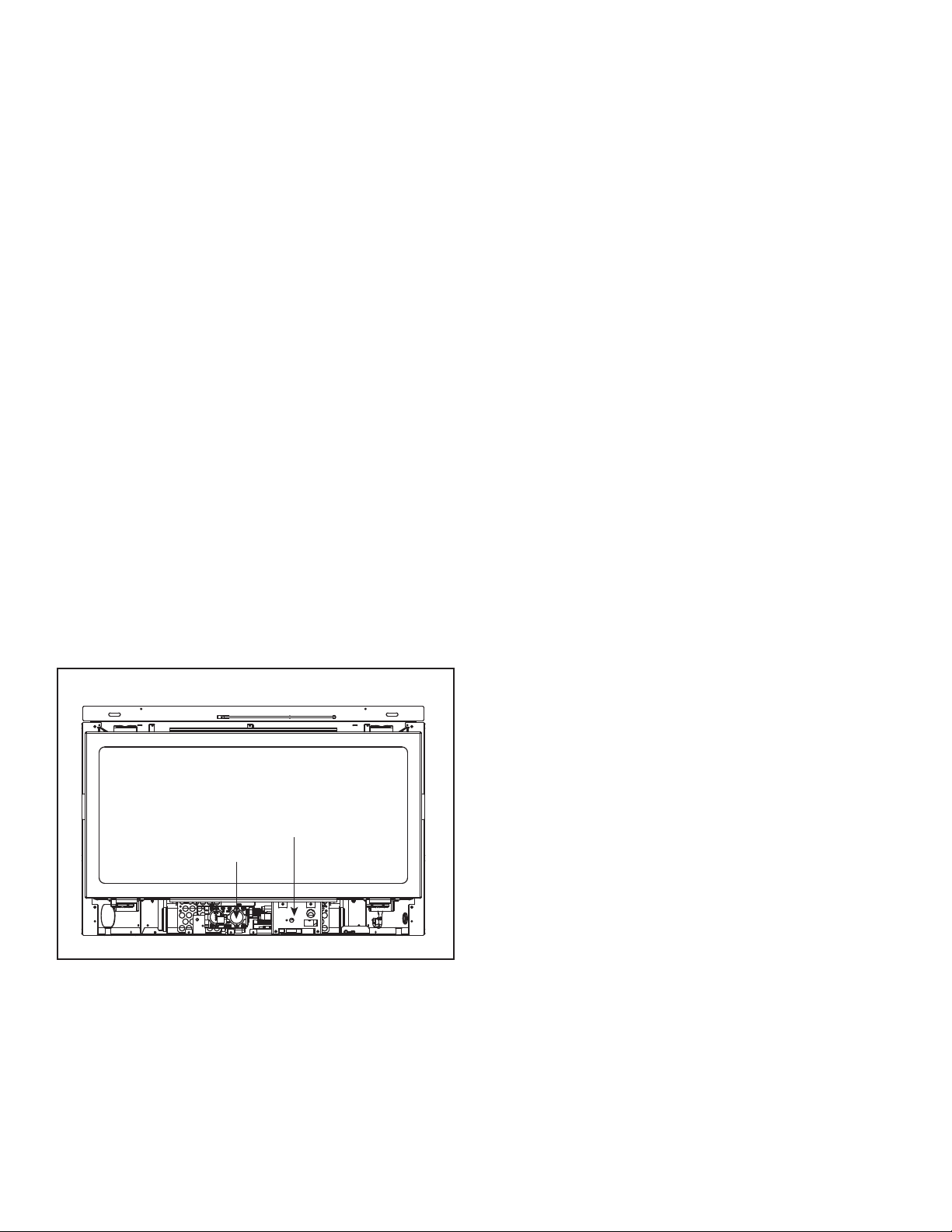
1. Access the control cavity of the appliance. See
Figure 3.3 for location. The decorative front or door
may need to be removed.
2. Locate the battery tray and insert four AA cell
batteries. Battery polarity must be correct or module
damage will occur. See Figure 3.3. A complete wiring
diagram is included in the Electrical section of the
appliance Installation Manual.
3. Turn the appliance on according to the instructions
below for the appropriate type of control:
Standard Wall Switch or Factory-Installed ON/OFF
Switch:
• Toggle the switch as you would under normal
circumstances.
Wireless Remote:
• Remote receiver is integrated into the ignition module
• Use the remote to turn the appliance on.
• To preserve battery life, do not use the HI/LO fl ame or
THERMOSTAT options.
Ignition Module:
• Locate the ignition module in the control cavity.
• Slide the ON/REMOTE/OFF switch to the ON
position.
CONTROL CAVITY
VALVE
Figure 3.3 Control Cavity - Valve Location
To Return to Operation Using Electrical (AC) Power
Standard Wall Switch or Factory-Installed ON/OFF
Switch:
• Toggle the switch to OFF and remove the batteries
from the battery tray. Replace door or decorative
front on appliance.
Wireless Remote:
• Slide the ON/REMOTE/OFF switch to the REMOTE
position. Remove the batteries from the battery tray.
Replace decorative front on appliance.
H. Heat Management
Heat Output
Heat Output is managed through the RC200 remote con-
trol that comes standard with the fi replace.
• Turn the appliance on and off.
• Adjust the height of the fl ame by varying the input using
the remote control.
• Adjust the fan speed.
For more information, see the instructions that accompany
the remote control.
Loading ...
Loading ...
Loading ...