Loading ...
Loading ...
Loading ...
Page 5 of 11506318-03C mrcool.com
Electrical Connections
Electrical Shock Hazard!
Turn OFF electric power before connecting
unit, performing any maintenance or
removing panels or doors. More than one
disconnect may be required to turn off all
power.
FAILURE TO DO SO COULD RESULT IN
BODILY INJURY OR DEATH.
WARNING
Be sure to check all local codes to determine that the unit
is installed accordance with local requirements. Consult
the National Electric Code for wire size requirements. Use
60 C wire or higher. Always provide ground connections to
the outdoor unit. Power supply must agree with rating on
unit nameplate.
Provide line voltage power supply to unit from a properly
sized disconnect switch. Route power and ground wires
from disconnect switch to unit. Line voltage connections
are made at the line side of the contactor in the control box
of the outdoor unit. Follow the appropriate wiring diagram
attached to inside of the access panel.
Proper circuit protection recommendations are indicated
on Unit Rating Plate. Time delay fuses are required to
prevent blowing due to starting current (the current in rush
when equipment starts is referred to as the Locked Rotor
Amps or (LRA). A fuse of this kind properly sized will give
maximum equipment protection.
Use copper wire only between disconnect switch and unit.
Remove access panel to gain access to unit wiring. Extend
wires from disconnect through power wiring hole provided
and into unit control box. Flexible conduit is required for the
swing out control box feature.
The unit cabinet must have an uninterrupted or unbroken
ground to minimize personal injury if an electrical fault
should occur. The ground may consist of electrical wire
or metal conduit when installed in
accordance with
existing electrical codes. Failure to follow this warning
WARNING
Connect ground wire to ground connection in control box
for safety. Connect power wiring to contactor.
High voltage power connections to 3-phase models is made
Control Wiring
The control voltage is 24 VAC. NEC Class I insulated 18
AWG is required for control wiring. For lengths longer than
150 feet, contact your local distributor for technical service.
Ensure the room thermostat is properly installed per
instructions shipped with room thermostat. Generally the
thermostat should not be exposed to sunlight, drafts or
vibration and should not be mounted on exterior walls.
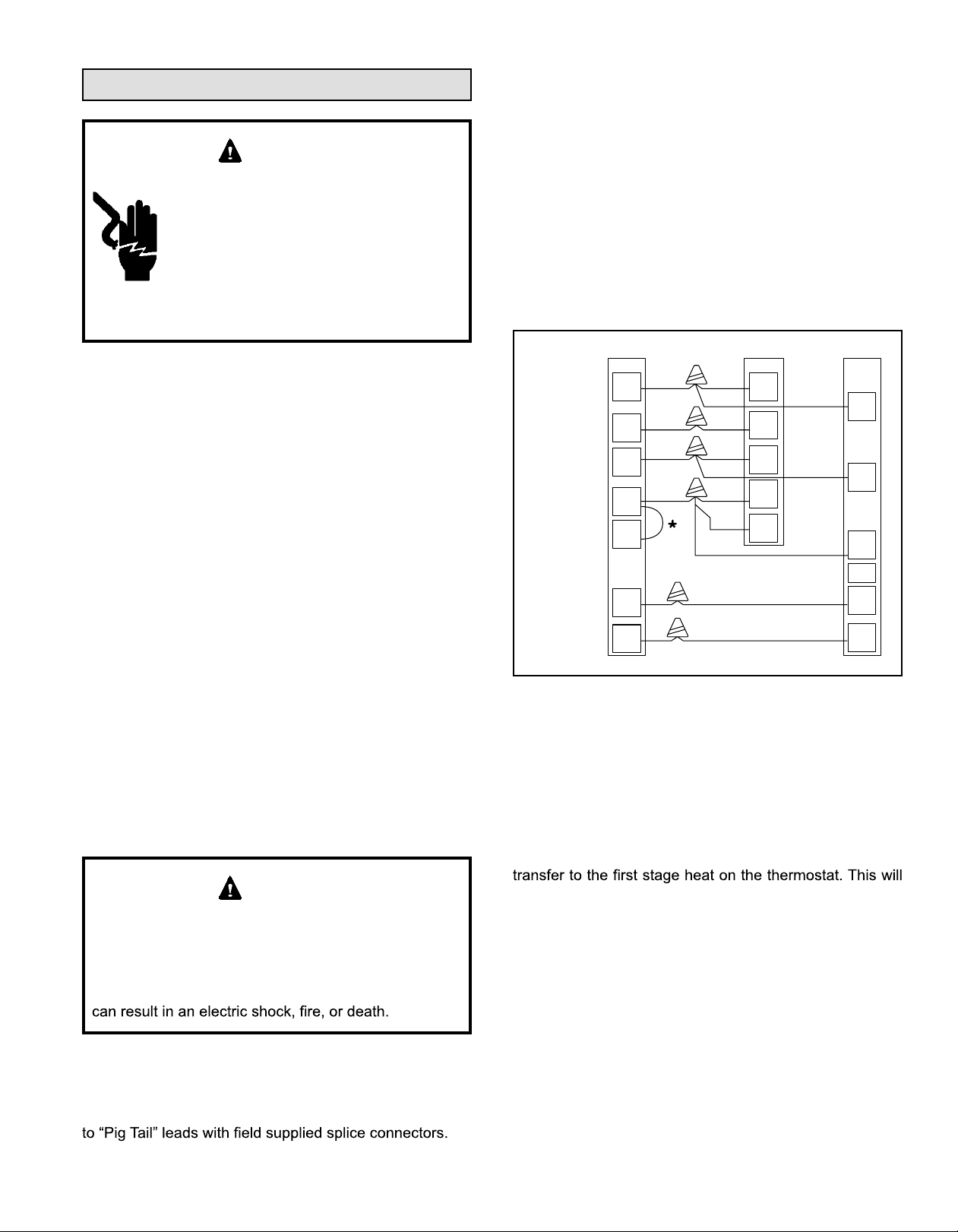
Low voltage control wire connections should be made
to the screw connection terminal board mounted on the
defrost control as shown. All low voltage control wiring
must be separated from incoming power leads.
Thermostat Air Handler Heat Pump
24 VAC HOT
INDOOR FAN
24 VAC COM
HEAT
STAGE 2
EMERGENCY
HEAT
RVS
COOLING
COOL / HEAT
STAGE 1
R
G
C
W
E
O
Y
R
G
C
R
G
C
O
R
B
W
W1
W2
L
Y1
W1
RED
GREEN
BLUE
WHITE
ORANGE
YELLOW
F0000453
Figure 2.
Heat Pump Application with Electric Heat
Emergency Heat (Heating Heat Pump)
If selector switch on thermostat is set to the emergency
heat position, the heat pump will be locked out of the
heating circuit, and all heating will be electric heat ( if
applicable). A jumper should be placed between W and
E on the thermostat so that the electric heat control will
allow the indoor blower to cycle on and off with the electric
heat when the fan switch is in the AUTO position.
* Add Jumper on Subbase (Optional)
Loading ...
Loading ...
Loading ...