Owners' Guide Water Heaters
Welcome
Thank you for purchasing a Rinnai Tankless Water Heater. Before installing and operating this water heater, be sure to read these instructions completely and carefully to familiarize yourself with the water heater’s features and functionality.
To The Installer
- It is recommended that a trained and qualified professional who has attended a Rinnai training class complete the installation. The warranty may be voided due to any improper installation.
- A trained and qualified professional should have skills such as:
– Gas sizing
– Connecting gas lines, water lines, valves, and electricity
– Knowledge of applicable national, state, and local codes
– Installing venting through a wall or roof
– Training in installation of tankless water heaters. Training on Rinnai Tankless Water Heaters is accessible at www.trainingevents.rinnai.us
- Read all instructions in this manual before installing the water heater. The water heater must be installed according to the exact instructions in this manual.
- Proper installation is the responsibility of the trained and qualified professional.
- When installation is complete, leave this manual with the water heater (for internal/ indoor units) or give the manual directly to the consumer.
To The Consumer
- You must read the entire manual to properly operate the water heater and to have regular maintenance performed.
- Keep this manual for future reference.
- As when using any appliance generating heat, there are certain safety precautions you should follow. See section “2.1 Safety Precautions” for detailed safety precautions.
- Be sure your water heater is installed by a trained and qualified professional.
- If installing in the state of Massachusetts, you must read section “7.1 Massachusetts State Gas Regulations” in this manual.
Acronyms and Abbreviations
Table 1 provides a list of common acronyms and abbreviations used in this manual:
| ANSI |
American National Standards Institute |
| BTU |
British Thermal Unit |
| DHW |
Domestic Hot Water |
| GPM |
Gallons per minute |
| LP |
Liquid Propane |
| NG |
Natural Gas |
| PP |
Polypropylene |
| PRV |
Pressure Relief Valve |
| PSI |
Pounds per square inch |
| W.C. |
Inches water column |
About the Water Heater
Topics in this section
- Front View
- Bottom View
- Components
- Specifications
- Dimensions
- Accessories
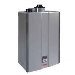
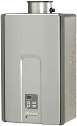
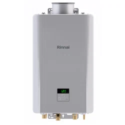
1. Front View
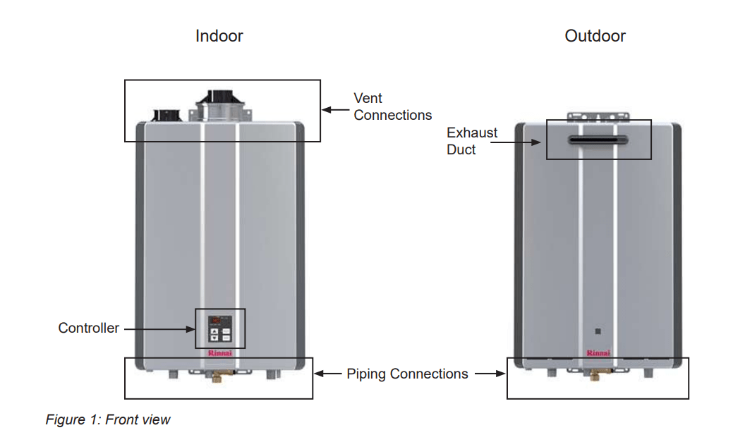
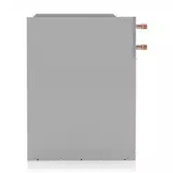
2. Bottom View
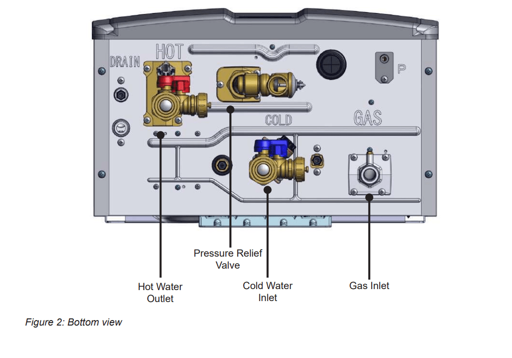
3. Components
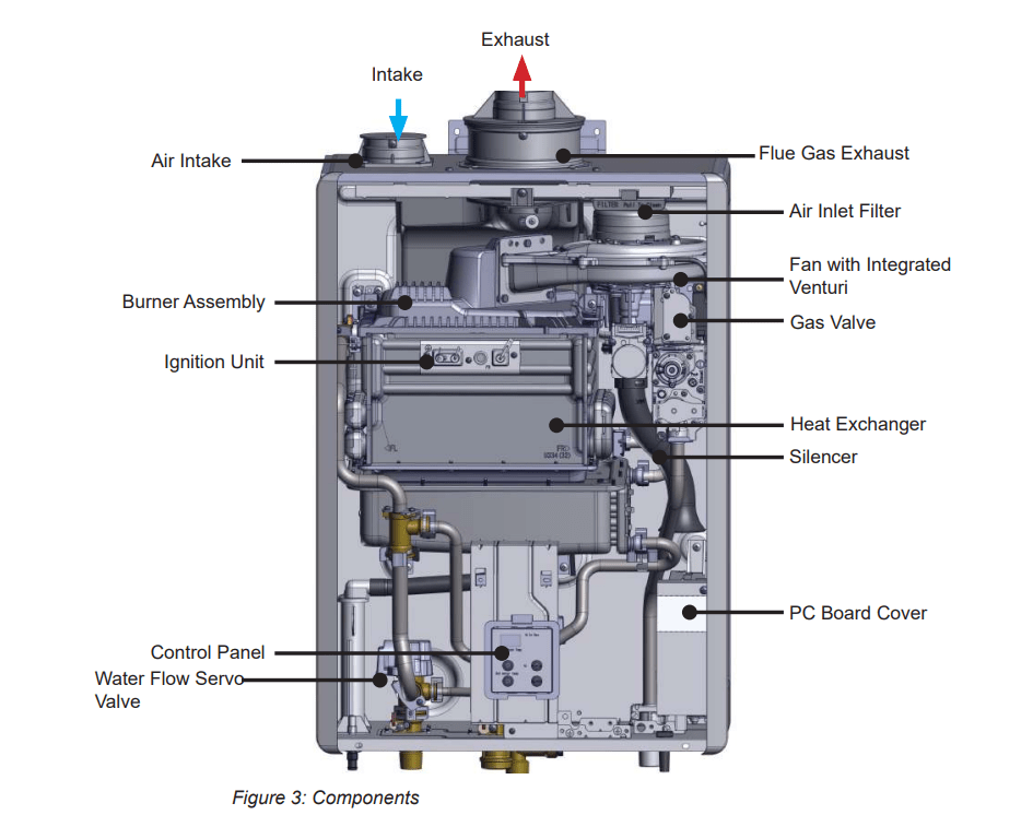
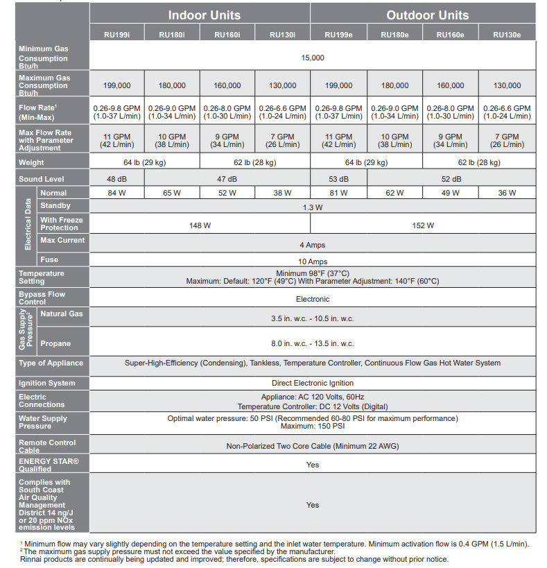
4. Specifications
Table 2: Specifications
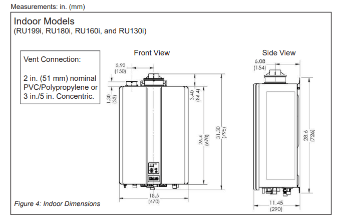
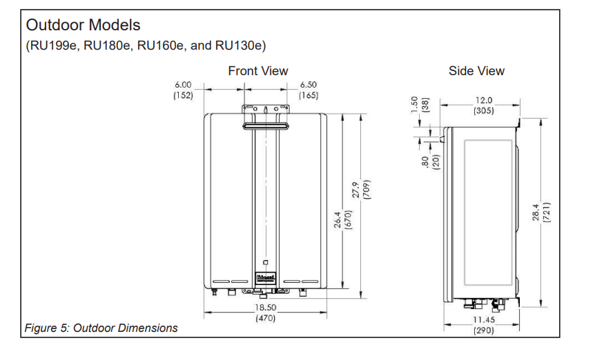
5. Dimensions
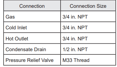
5.1 Supply Connections
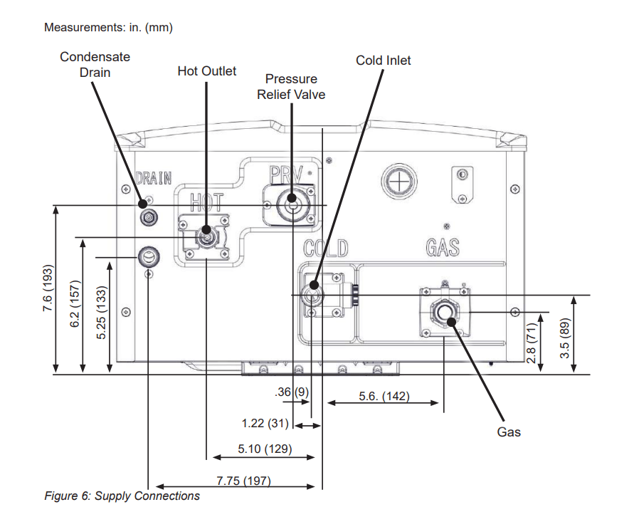
Table 3: Supply Connections
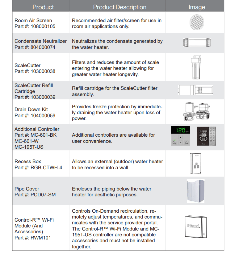
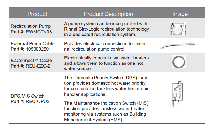
6. Accessories
Table 4: Accessories
Operation
Topics in this section
- Safety Precautions
- Start-up Information
- Control Panel
- Basic Operation Settings
- Diagnostic Codes
1. Safety Precautions
If the information in these instructions is not followed exactly, a fire or explosion may result causing property damage, personal injury, or death.
- Do not store or use gasoline or other flammable vapors and liquids in the vicinity of this or any other appliance.
- Before operating, smell all around the appliance area for gas. Be sure to smell next to the floor because some gas is heavier than air and will settle on the floor.
- WHAT TO DO IF YOU SMELL GAS – Do not try to light any appliance.
– Do not touch any electrical switch; do not use any phone in your building.
– Immediately call your gas supplier from a neighbor’s phone. Follow the gas supplier’s instructions.
– If you cannot reach your gas supplier, call the fire department.
- Installation and service must be performed by a trained and qualified professional, service agency or the gas supplier.
- Keep the area around the appliance clear and free from combustible materials, gasoline, and other flammable vapors and liquids.
- Do not use this appliance if any part has been under water. Immediately call a trained and qualified professional to inspect the appliance and to replace any part of the control system and any gas control which has been under water.
- Should overheating occur or the gas supply fail to shut off, turn off the manual gas control valve to the appliance.
- Use only your hand to push in or turn the gas control knob. Never use tools. If the knob will not push in or turn by hand, do not try to repair it, call a trained and qualified professional. Force or attempted repair may result in a fire or explosion.
- This appliance does not have a pilot. It is equipped with an ignition device which automatically lights the burner. DO NOT try to light the burner by hand.
- Do not use an extension cord or an adapter plug with this appliance.
- Any alteration to the appliance or its controls can be dangerous and will void the warranty.
- If you install this water heater in an area that is known to have hard water or that causes scale build-up the water must be treated and/or the heat exchanger flushed regularly. Rinnai provides a “Scale Control System” that offers superior lime scale prevention and corrosion control by feeding a blend of control compounds into the water supply. Damage and repair due to corrosive compounds in the air is not covered by warranty.
- Keep the combustion air vent pipe location free of chemicals, such as chlorine or bleach, that produce fumes. These fumes can damage components and reduce the life of your appliance. Damage and repair due to scale in the heat exchanger is not covered by warranty.
- Always check the water temperature before entering a shower or bath.
- Do not adjust the parameter settings unless specifically instructed to do so.
2. Operating Instructions
FOR YOUR SAFETY READ BEFORE OPERATING
WARNING
If you do not follow these instructions exactly, a fire or explosion may result causing property damage, personal injury or loss of life.
A. This appliance does not have a pilot. It is equipped with an ignition device which automatically lights the burner. Do not try to light the burner by hand.
B. BEFORE OPERATING, smell all around the appliance area for gas. Be sure to smell next to the floor because some gas is heavier than air and will settle on the floor.
WHAT TO DO IF YOU SMELL GAS
- Do not try to light any appliance.
- Do not touch any electric switch; do not use any phone in your building.
- Immediately call your gas supplier from a neighbor’s phone. Follow the gas supplier’s instructions.
- If you cannot reach your gas supplier, call the fire department.
C. Use only your hand to push in or turn the gas control valve. Never use tools. If the gas control valve will not turn by hand, do not try to repair it, call a qualified service technician. Force or attempted repair may result in a fire or explosion.
D. Do not use this appliance if any part has been under water. Immediately call a qualified service technician to inspect the appliance and to replace any part of the control system and any gas control which has been under water.
OPERATING INSTRUCTIONS
- STOP! Read the safety information above.
- Set the temperature controller to lowest setting.
- Turn off all electric power to the appliance.
- This appliance does not have a pilot. It is equipped with an ignition device which automatically lights the burner. Do not try to light the burner by hand.
- Turn the manual gas control valve located at gas inlet of appliance clockwise to the OFF position.

- Wait five (5) minutes to clear out any gas. Then smell for gas, including near the floor. If you smell gas, STOP! Follow “B” in the safety information above. If you don’t smell gas, go to the next step.
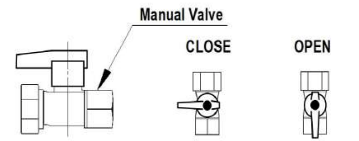
- Turn the manual gas valve located at gas inlet of appliance counterclockwise to the full ON position.

- Turn on all electric power to the appliance.
- Set the temperature controller to desired setting.
- If the appliance will not operate, follow the instructions “To Turn Off Gas To Appliance” and call your service technician or gas supplier.
TURN OFF GAS TO APPLIANCE
- Set the temperature controller to lowest setting.
- Turn off all electric power to the appliance if service is to be performed.
- Turn the manual gas control valve located at gas inlet of appliance clockwise to the OFF position.

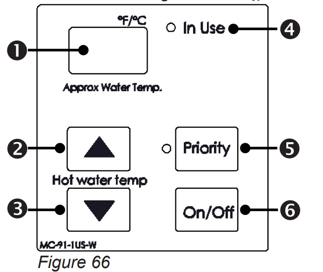
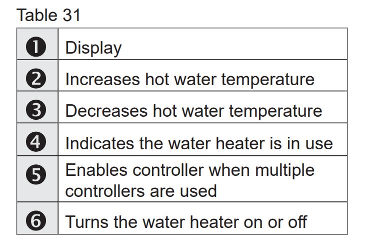
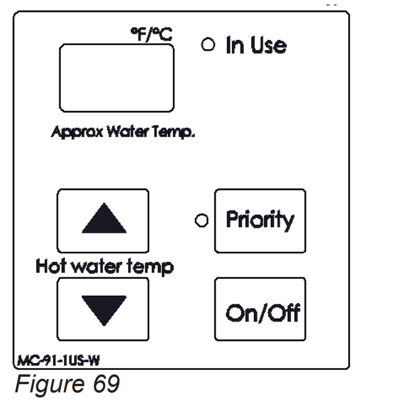
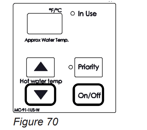
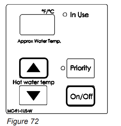
3. Control Panel
The controller panel allows you to adjust the water temperature, lock the controller on a set temperature, and view diagnostic information.
3.1 Setting the Controller to Mute
To eliminate the beeps when keys are pressed, press and hold both the  (Up) and
  (Down) buttons at the same time until a beep is heard (approximately 3 seconds). Then, release both buttons.
To turn on the beeps, repeat the above steps.
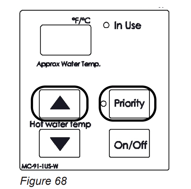
3.2 Locking the Controller
- To lock the internal controller, press and hold down the “Priority” button.
- While holding down the “Priority” button, press the
 (Up) button until a beep is heard (approximately 5 seconds). Then, release both buttons at the same time.
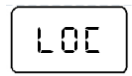 appears in the display indicating the controller is locked.
NOTE
The display flashes between 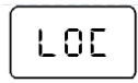 and the set temperature to indicate the controller is locked.
To unlock the controller, follow the above steps.
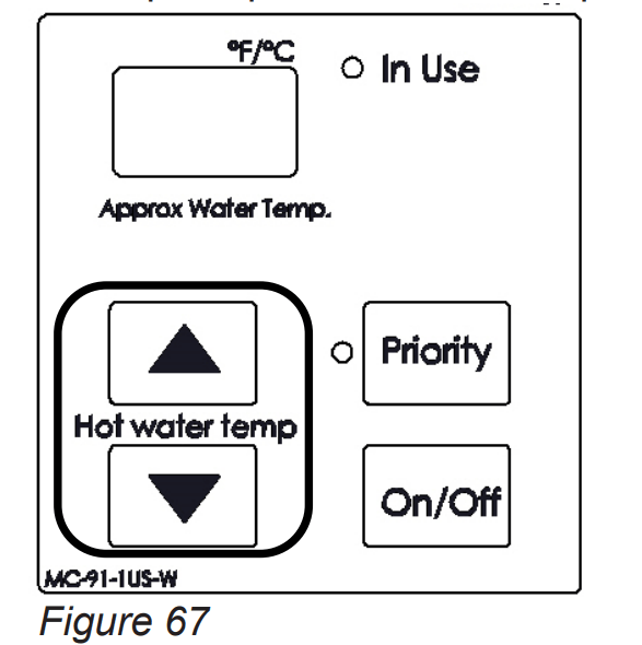
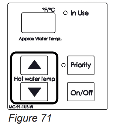
4. Setting the Temperature
This water heater requires a minimum flow rate to operate. This rate can be found on the specification page in this manual. In some cases when you are not getting hot water or if the water alternates between hot and cold, it is due to the water flow being below or close to the minimum flow rate. Increasing the flow rate should resolve these problems in these cases.
If you are experiencing issues with higher temperature settings, then reduce the temperature setting. Selecting a temperature closer to that which is actually used at the faucet will increase the amount of hot water being delivered to the faucet, due to less cold water mixing at the fixture.
DANGER
Water temperatures over 125°F (52°C) can cause severe burns or scalding resulting in death.
Hot water can cause first degree burns with exposure for as little as:
- 3 seconds at 140°F (60°C)
- 20 seconds at 130°F (54°C)
- 8 minutes at 120°F (49°C)
Children, disabled, or elderly are at highest risk of being scalded.
Feel water before bathing or showering.
IMPORTANT
- While any hot water is being provided, the temperature setting can only be adjusted between 98°F and 110°F.
- Check local codes for the maximum water temperature setting allowed when used in nursing homes, schools, day care centers, and all other public applications.
- If a newly installed water heater with a controller has not been powered for at least 6 hours then the temperature will return to the default setting of 104°F (40°C) if power is interrupted.
- There may be a variation between the temperature displayed on the temperature controller and the temperature at the tap due to weather conditions or the length of pipe to the water heater.
The controller buttons shown below are located on the outside front panel for internal (indoor) water heaters. For external (outdoor) water heaters, open the front panel to access the controller buttons.
- If the water heater is off, press the “On/Off” button to turn on.
- The “Priority” button enables a controller if multiple controllers are being used. If the “Priority” light is off, then press the “Priority” button on the temperature controller. The orange “Priority” light will glow indicating that this controller is controlling the temperature and that the water heater is ready to supply hot water. The priority can only be changed while no hot water is running.
- Press the
 (Up) or
  (Down) buttons to obtain the desired temperature setting. All hot water sources are able to provide water at this temperature setting until it is changed again at this or another temperature controller.
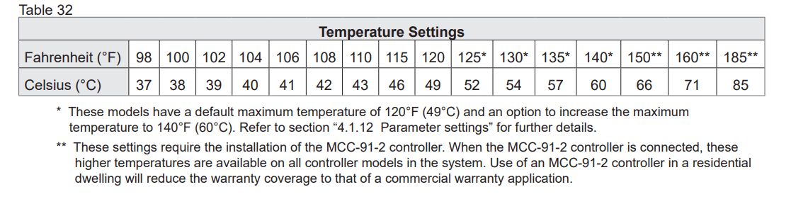
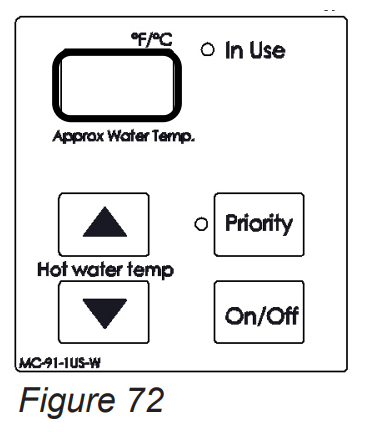
4.1 Available Temperatures with an Internal Controller
The water heater can deliver water at only one temperature setting at a time. The available temperatures are provided below. A temperature lower than 98°F (37°C) can be obtained at the tap by mixing with cold water.
To change the temperature scale from Celsius to Fahrenheit or vice versa, press and hold the “On/Off” button on the controller for 5 seconds while the water heater is OFF.
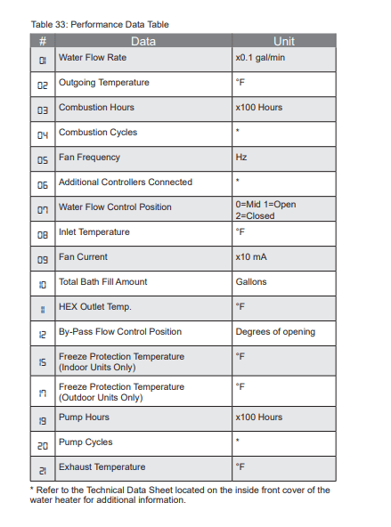
5. Performance Data
To obtain performance data:
- Press and hold the
 (Down) button.
- While holding the
 (Down) button for 2 seconds, press and hold the “On/Off” button (hold both buttons simultaneously).
- Use the
 (Up) and
  (Down) buttons to scroll to the desired information described in the Performance Data Table.
- To exit performance data, repeat step 2 above.
- When complete, the set temperature appears in the display.
6. Diagnostic Codes
To display diagnostic codes:
Turn off the water heater by pressing the “On/Off” button.
Press and hold the “On/Off” for 2 seconds and then the  (Up) button simultaneously.
The last nine maintenance codes display and flash one after the other.
To exit diagnostic codes and return the water heater to normal operation, press and hold the “On/Off” button for 2 seconds and then the  (Up) button simultaneously.
Turn on the water heater by pressing the “On/Off” button.
WARNING
Some of the checks below should be performed by a trained and qualified professional. Consumers should never attempt any action that they are not qualified to perform.
 |
Power interruption during bath fill (Water will not flow when power returns) |
| |
- Turn off all hot water taps. Press ON/ OFF twice.
|
 |
By-Pass Flow Control |
| |
- Measure resistance values of the by-pass flow control.*
- Replace By-Pass flow control device
|
 |
Air Supply or Exhaust Blockage/ Condensate Trap is Full |
| |
- Ensure condensate line is not blocked.
- Ensure internal air filter is clean with no obstructions. (Indoor Water Heaters Only)
- Ensure High Altitude setting. (See Parameter Settings)
- Ensure Combustion air and Exhaust vents are not blocked and approved venting materials are being used. (Indoor Water Heaters Only)
- Ensure vent length is within limits. (Indoor Water Heaters Only)
- Check fan for debris and ensure wheel turns freely.
- Verify check valve is not stuck between fan casing and burner body.
|
 |
No Ignition (Heater Not Turning On) |
| |
- Check that the gas is turned on at the water heater, meter, or cylinder.
- If the system is propane, make sure that gas is in the tank.
- Ensure gas type and inlet gas pressure are correct.
- Bleed all air from gas lines.
- Check the ground wire for the PC Board.
- Ensure flame rod wire is connected.
- Ensure igniter is operational.*
- Check gas solenoid valves for open or short circuits.*
- Verify gas orifice is correct.
|
 |
No Flame |
| |
- Check that the gas is turned on at the water heater, gas meter, or cylinder.
- If the system is propane, make sure that gas is in the tank.
- Ensure flame rod wire is connected.
- Ensure gas type and inlet gas pressure is correct.
- Bleed all air from gas lines.
|
 |
Heat Exchanger Overheat |
| |
- Measure resistance of Overheat Switch.*
- Check heat exchanger surface for hot spots which indicate blockage due to scale build-up.
- Refer to instructions in manual for flushing heat exchanger. Hard water must be treated to prevent scale build up or damage to the heat exchanger.
- Ensure it is not in forced Hi setting.
|
 |
Venturi Control |
| |
- Ensure the Venturi motor is operating correctly.*
- Replace gas valve assembly.
- Clear diagnostic code by resetting the main power supply to the water heater
|
 |
High Outgoing Temperature |
| |
(safety shutdown because water heater is too hot)
- Confirm fan motor is functioning correctly.
- Replace the gas valve assembly.
|
 |
Venturi Blockage |
| |
- First, follow the recommended solutions for Diagnostic Code 10.
- If the Code 10 solutions do not correct the problem, ensure the Venturi is not blocked.
- Please call Rinnai technical department.
|
 |
Electrical Grounding |
| |
- Check all components for electrical short.
|
 |
Data Transfer Error |
| |
- If the PCB has been replaced, ensure the data transfer process has been completed.
|
 |
Condensate Pump (Accessory) |
| |
- Confirm wire connections and harness are good.
- Ensure condensate reservoir is empty and condensate pump is operating.
|
 |
Outgoing Thermistor |
| |
- Check sensor wiring for damage.
- Measure resistance of sensor.*
- Clean sensor of scale build-up.
- Replace sensor.
|
 |
Heat Exchanger Thermistor |
| |
- Follow the steps above for Code 32 for troubleshooting.
|
 |
Exhaust Thermistor |
| |
- Check sensor wiring for damage.
- Measure resistance of sensor.*
- Replace sensor.
|
 |
Freeze Protection Thermistor |
| |
- Follow the steps above for Code 38 for troubleshooting.
|
 |
Inlet Thermistor |
| |
- Check sensor wiring for damage.
- Measure resistance of sensor.*
- Clean sensor of scale build-up.
- Replace sensor.
|
 |
Gas Valve |
| |
- Check flame rod and wire for damage.
- Check gas solenoid valve for open or short circuit.*
- Replace gas valve assembly.
- Please call Rinnai technical department
|
 |
High Exhaust Gas Temperature |
| |
- Ensure Heat Exchanger fins are clean and not blocked.
- Confirm inlet water temperature is not too high.
- Clear diagnostic code by resetting the main power supply to the water heater.
|
 |
Combustion Fan |
| |
- Check the motor wire harness for loose or damaged connections.
- Measure resistance of motor wire harness.*
- Ensure the combustion fan spins freely.
|
 |
Recirculation Low Flow |
| |
- Ensure bypass plug is removed and bypass filter is installed. (COV Mode)
- Ensure both the inlet water filter and bypass filter are clean and free of debris.
- Ensure Parameter setting are correctly set for recirculation mode.
- Ensure Pump supply voltage.
- Ensure air is removed from the recirculation line.
|
 |
Water Flow Control |
| |
- Measure resistance values of the water flow control.*
- The water flow control valve has failed to close during the bath fill function. Immediately turn off the water and discontinue the bath fill function. Contact a trained and qualified professional to service the appliance.
|
 |
PC Board |
| |
|
 |
Solenoid Valve Circuit |
| |
- Ensure dip switch on PC board is in the OFF position.
- Ensure gas control wire is not loose or damaged.
- Ensure heater circuit is not grounded.
- Replace PC Board.
|
 |
Flame Rod |
| |
- Check flame rod and wire for damage.
- Verify HEX is not leaking.
|
 |
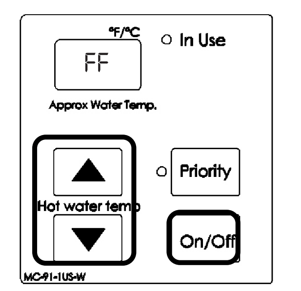
Maintenance Indicator |
| |
- Placeholder in Diagnostic code history indicating that a service provider performed maintenance or service.
- Enter this code after performing service by pressing
 (Up) , (Up) ,  (Down) and On/Off simultaneously. (Down) and On/Off simultaneously.
- FF is visible on the monitor.
|
 |
(SS) Service Soon (Flush Heat Exchanger) |
| |
- SS is a time-based service indicator set during installation. See section “4.12.1 Parameter Settings” for additional details on setting and changing the SS indicator.
- SS indicates that it is time for service. The heat exchanger should be flushed to prevent damage (refer to section “6.3 Flushing the Heat Exchanger” for more information). Hard water must be treated to prevent scale build-up or damage to the heat exchanger.
- To reset the SS code, push the On/Off button on the temperature controller 5 times in 5 seconds.
|
|

|
NO CODE - Nothing happens when water flow is activated
- Verify you have at least the minimum flow rate required to fire unit.
- Measure the resistance of the water flow control sensor.*
- Clean inlet water supply filter.
- On new installations ensure hot and cold water lines are not reversed.
|
Maintenance
Topics in this section
- Maintenance
- Cleaning and Inspecting the Air Filter (Indoor Units Only)
- Flushing the Heat Exchanger
- Draining the Water Heater
1. Maintenance
This water heater must be inspected annually by a trained and qualified professional. Repairs and maintenance shall be performed by a trained and qualified professional. The trained and qualified professional must verify proper operation after servicing.
WARNING
To protect yourself from harm, before performing maintenance:
- Turn off the electrical power supply by unplugging the power cord or by turning off the electricity at the circuit breaker. (The temperature controller does not control the electrical power.)
- Turn off the gas at the manual gas control valve, usually located immediately below the water heater.
- Turn off the incoming water supply. This can be done at the isolation valve immediately below the water heater or by turning off the water supply to the building.
WARNING
Keep the appliance area clear and free from combustible materials, gasoline, and other flammable vapors and liquids.
The following maintenance items are required for the proper operation of your water heater.
CLEANING
It is imperative that control compartments, burners, condensate collection and disposal system, vent screens and circulating air passageways of the appliance be kept clean.
BURNER
Check burner flame for proper color. Once ignited, the flame must cover the surface of the burner. The flame must burn with a clear, blue, stable flame. If the flame does not have this appearance, complete the following steps:
- Turn off and disconnect electrical power. Allow to cool.
- Remove the front panel by removing four screws.
- Use a vacuum to remove dust from the main burner and fan blades. Do not use a wet cloth or spray cleaners on the burner. Do not use volatile substances such as benzene and thinners; they may ignite or fade the paint.
- Use soft dry cloth to wipe cabinet.
CONDENSATE COLLECTION AND DISPOSAL SYSTEM
Periodic inspection and cleaning of the condensate collection and disposal system.
Ensure condensate is flowing and the end of the drain is open to the atmosphere.
VENT SYSTEM
Periodic cleaning and inspection of the vent system including screens in the vent termination.
The vent system should be inspected for blockages including snow or other debris or damage. If the vent is blocked and cannot be easily cleared, contact a trained and qualified professional.
MOTORS
Motors are permanently lubricated and do not need periodic lubrication. However you must keep fan and motor free of dust and dirt by cleaning annually.
TEMPERATURE CONTROLLER
Use a soft damp cloth to clean the temperature controller. Do not use solvents.
LIME/SCALE BUILD-UP
Scale build-up is caused by hard water and can be accelerated if the water heater is set at a high temperature. Refer to section “6.3 Flushing the Heat Exchanger” for more information. Refer to section “Water Quality Guidelines” to determine if your water needs to be treated or conditioned. The water must be potable, free of corrosive chemicals, sand, dirt, or other contaminates. It is up to the installer to ensure the water does not contain corrosive chemicals, or elements that can affect or damage the heat exchanger. Water that contains chemicals exceeding the levels required affect and damage the heat exchanger. Replacement of the heat exchanger due to water quality damage is not covered by the warranty.
SNOW ACCUMULATION
Keep the area around flue terminal free of snow and ice. The water heater will not function properly if the combustion air or exhaust vent pipes are impeded (blocked or partially blocked) by obstructions.
Keep the condensate drain line free of snow and ice. Ensure the line is not blocked or clogged and that condensate is flowing freely.
COASTAL INSTALLATIONS
Installations located in or near coastal areas may require additional maintenance due to corrosive airborne ocean salt. If corrosion is observed on the body of the water heater, the water heater shall be inspected to ensure proper operation and if necessary, repaired or replaced.
FILTERS
- Water Filter — Clean the inlet water filter by closing the cold and hot water inlet isolation (shut-off)t valves. Put a bucket under the filter at the bottom of the water heater to catch any water that is contained inside the unit. Unscrew the water filter. Rinse the filter to remove any debris. Install the filter and open the isolation valves.
- Air Filter — See section “6.2 Cleaning and Inspecting the Air Filter” for more information.
PRESSURE RELIEF VALVE
Operate the pressure relief valve manually once a year. In doing so, it will be necessary to take precautions with regard to the discharge of potentially scalding hot water under pressure. Ensure discharge has a safe place to flow. Contact with your body or other property may cause damage or harm.
WARNING
Testing the pressure relief valve should only be performed by a trained and qualified professional. Water discharged from the pressure relief valve could cause severe burns instantly or death from scalds.
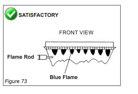
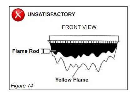
VISUAL INSPECTION OF FLAME
Verify proper operation after servicing. The burner must flame evenly over the entire surface when operating correctly. The flame must burn with a clear, blue, stable flame. See the parts breakdown of the burner for the location of the view ports.
The flame pattern should be as shown in the images below:
FREEZE PROTECTION
Make sure in case of freezing weather that the water heater and its water lines are adequately protected to prevent freezing. Damage due to freezing is not covered by the warranty. Refer to the “Freeze Protection” section (Section 4.2 Choose an Installation Location > Freeze Protection). The water heater may be drained manually. However, it is highly recommended that drain down solenoid valves be purchased and installed, which will automatically drain the water heater if power is lost. (The condensate trap drain plug and Pressure Relief Valve are not affected by the auto drain down solenoid valves and will have to be manually opened.)
WINTERIZATION
The following recommendations are intended to suggest practices that are effective for winterizing the water heater. They should be used as a guide only. No liability is assumed for any issues resulting from the use of this information.
Note: See section “6.4 Draining the Water Heater” for detailed instructions on:
- Draining the water heater
- Running a low volume of water through the water heater to prevent freezing
- Steps to take when the water heater or external pipes have frozen.
Gas
Shut off the gas to the water heater. It is generally preferable to shut off the gas service to the entire location if gas is not going to be used.
Water
- Shut off the cold water supply to the water heater. It is generally preferable to shut off the water to the entire location if water is not going to be used.
- Drain the water heater by opening the drain valves on the cold water line and hot water line.
- Open several hot water taps and remove the filter assembly at the water inlet in order to allow room for expansion in case there is water in the lines that freeze.
Condensate
Drain the condensate using the condensate drain port on the bottom of the water heater.
Electric
Disconnect the power supply by either unplugging the electrical cord or by turning off the circuit breaker to the water heater to prevent potential damage from irregular power surges or interruptions.
2. Cleaning and Inspecting the Air Filter (Indoor Units Only)
INSPECTION
- To maintain optimum performance, periodically inspect the air filter.
- If the air filter appears to have lint and/or dust build up, follow the cleaning procedure described below.
- If the air filter appears damaged, contact a trained and qualified professional for a replacement air filter assembly
NOTE
Do not operate this water heater if the air filter is not in place.
CLEANING
- Power OFF the water heater
• Push the “On/Off” button located on the right-hand side of the controller. The display will go blank when the power is off.
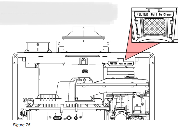
- Remove the front panel.
• Remove the four screws securing the front panel.
• Remove the front panel and locate the filter at the upper right-hand corner of the water heater.
• Remove the air filter by pulling out the “FILTER Pull to Clean” tab
- Clean the Air Filter • With mild dish soap and a soft bristle brush, scrub the filter area of the air filter door.
• With clean water, rinse the soap off the filter.
- Dry the Air Filter: With a lint free towel, dry the air filter.
- Inspect and Replace the Air Filter
• Inspect the air filter for any debris that may restrict air flow to the water heater.
• If the filter still appears dirty repeat the cleaning steps.
• Replace the air filter.
- Power ON the water heater.
3. Flushing the Heat Exchanger
This water heater includes a service indicated/ reminder (Service Soon, SS). When selected in the parameter settings, an SS code will display on the controller indicating that it is time to flush and service the water heater. Failure to flush the appliance will cause damage to the heat exchanger. Damage caused by lime build-up is not covered by the water heater’s warranty. Rinnai strongly recommends installation of isolation valves to allow for flushing of the heat exchanger.
- Turn off power at the controller.
- Disconnect electrical power to the water heater.
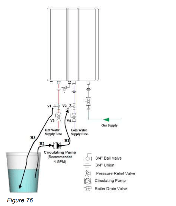
- Close the shutoff valves on both the hot water and cold water lines (V3 and V4).
- Connect pump outlet hose (H1) to the cold water line at service valve (V2).
- Connect drain hose (H3) to the hot water line at service valve (V1).
- Pour four gallons of undiluted virgin, food grade, white vinegar into pail.
- Place the drain hose (H3) and the hose (H2) to the pump inlet into the cleaning solution.
- Open both service valves (V1 and V2) on the hot water and cold water lines.
- Operate the pump and allow the vinegar to circulate through the water heater for at least 1 hour at a rate of four gallons per minute (15.1 liters per minute).
- Turn off the pump.
- Rinse the vinegar from the water heater as follows:
E. Remove the free end of the drain hose (H3) from the pail. Place in sink or outside to drain.
F.Close service valve (V2) and open shutoff valve (V4). Do not open shutoff valve (V3).
G. Allow water to flow through the water heater for five minutes.
H. Close shutoff valve (V4). When unit has finished draining remove the in-line filter at the cold water inlet and clean out any residue. Place filter back into unit and open valve (V4).
I. Close service valve (V1) and open shutoff valve (V3).
- Disconnect all hose
- Restore electrical power to the water heater.
NOTE
Scale build-up will affect the performance of the water heater. Water should be treated. Rinnai offers Southeastern Filtration’s “ScaleCutter Water Conditioning System” that offers superior lime scale prevention and corrosion control by feeding a blend of scale control compounds into the cold water supply.
4. Draining the Water Heater
WARNING
To avoid burns, wait until the equipment cools down before draining the water. The water in the appliance will remain hot after it is turned off.
If the water heater is not going to be used during a period of possible freezing weather, it is recommended that the water inside the water heater be drained.
To manually drain the water:
- Shut off cold water supply and gas supply.
- Turn off the temperature controller.
- Disconnect the power to the water heater.
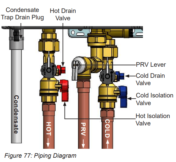
- Close the hot and cold isolation valves.
- Open the pressure relief valve (PRV) lever.
- Open the hot and cold drain valves.
- Remove the condensate trap drain plug and allow to drain.
To resume normal operation:
- Confirm that the gas supply is turned off, all taps are closed and PRV lever is closed.
- Insert the condensate trap drain plug.
- Close the hot and cold drain valves.
- Open the cold and hot water isolation valves.
- Open a tap and confirm that water flows, and then close.
- Connect power to the water heater.
- After confirming that the temperature controller is off, turn on the gas supply.
- Turn on the temperature controller.
Running a low volume of water through the water heater to prevent freezing:
If the temperature exceeds the ability of the water heater to freeze protect itself, or if power is lost, the following steps may prevent the water heater and external piping from freezing. Units connected with EZConnect™ (2-unit link) should be drained to prevent freezing if not in use.
- Turn the water heater off and close the gas supply valve.
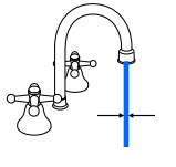
- Turn on a hot water tap to flow water about 0.1 gal/min (0.4 L/min) or where the stream is about 0.2 in. (5 mm) thick.
When the water heater or external piping has frozen:
- Do not operate the water heater if the unit or the external piping is frozen.
- Close the gas and water valves and turn off the power.
- Wait until the water thaws. Check by opening the water supply valve.
- Check the water heater and the piping for leaks.
Appendices
Topics in this section
- Massachusetts State Gas Regulations
- Wiring Diagram
- Ladder Diagram
- Pressure Drop and Water Flow Curves
- Guidelines for Additional Temperature Controllers
1. Massachusetts State Gas Regulations
For Gas Models Sold in Massachusetts
NOTICE BEFORE INSTALLATION:
This direct-vent appliance must be installed by a properly trained licensed professional. If you are not properly trained, you must not install this unit.
IMPORTANT: In the State of Massachusetts (248 CMR 4.00 & 5.00):
For all side wall horizontally vented gas fueled equipment installed in every dwelling, building or structure used in whole or in part for residential purposes, including those owned or operated by the Commonwealth and where the side wall exhaust vent termination is less than 7 ft above finished grade in the area of the venting, including but not limited to decks and porches, the following requirements shall be satisfied:
- INSTALLATION OF CARBON MONOXIDE DETECTORS. At the time of installation of the side wall horizontal vented gas fueled equipment, the installing plumber or gas fitter shall observe that a hard-wired carbon monoxide detector with an alarm and battery back-up is installed on the floor level where the gas equipment is to be installed. In addition, the installing plumber or gas fitter
- SIGNAGE. A metal or plastic identification plate shall be permanently mounted to the exterior of the building at a minimum height of 8 ft above grade directly in line with the exhaust vent terminal for the horizontally vented gas fueled heating appliance or equipment. The sign shall read, in print size no less than one-half (1/2) inch in size, “GAS VENT DIRECTLY BELOW. KEEP CLEAR OF ALL OBSTRUCTIONS.”
- INSPECTION. The state or local gas inspector of the side wall horizontally vented gas fueled equipment shall not approve the installation unless, upon inspection, the inspector observes carbon monoxide detectors and signage installed in accordance with the provisions of 248 CMR 5.08(2)(a)1 through 4.
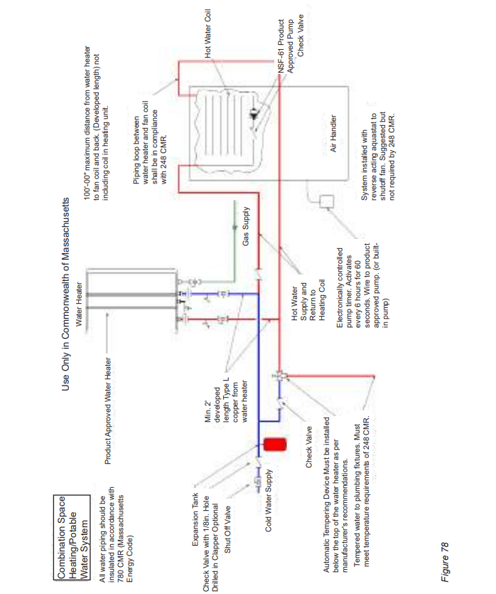
COMBINATION SPACE HEATING/POTABLE WATER SYSTEM (For Use In Commonwealth of Massachusetts)
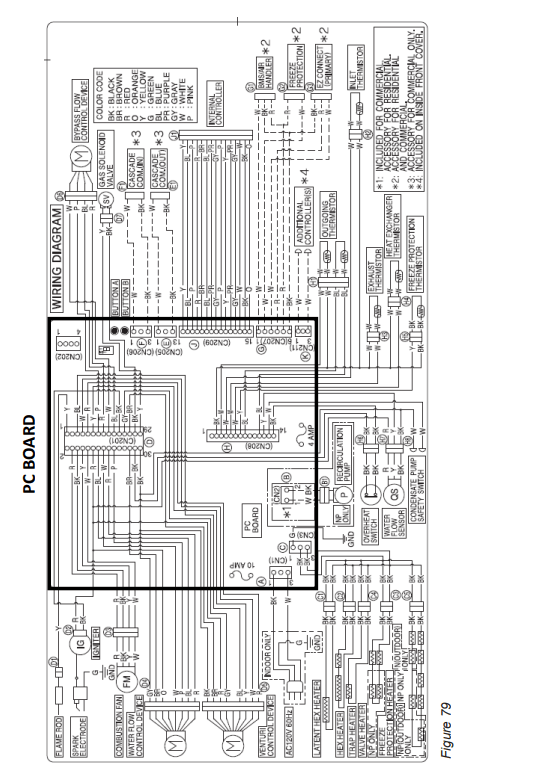
2. Wiring Diagram
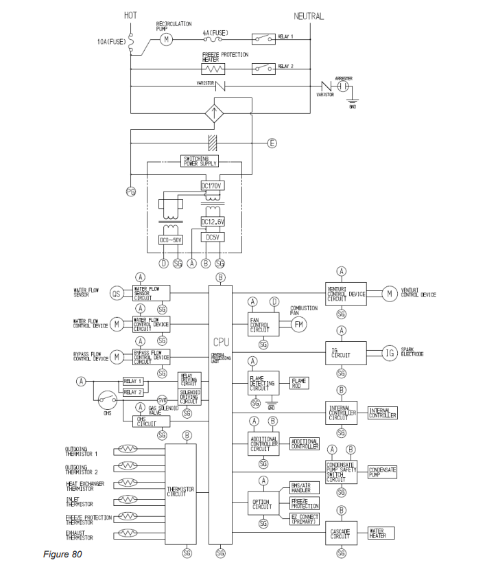
3. Ladder Diagram
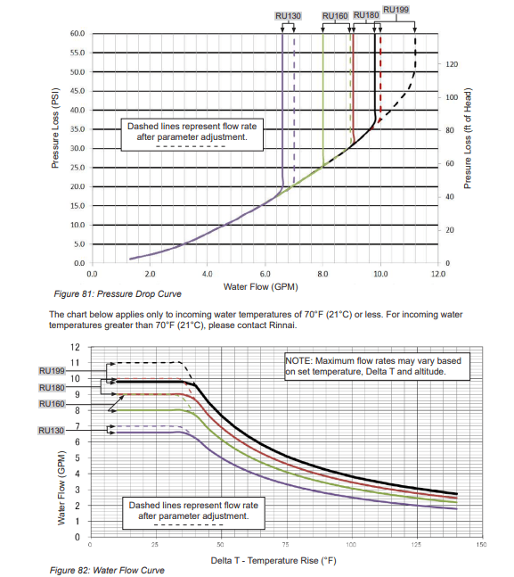
4. Pressure Drop and Water Flow Curves
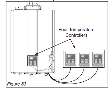
5. Guidelines for Additional Temperature Controllers
All Rinnai Tankless Water Heaters are equipped with an integrated digital temperature controller that allows for a precise water temperature setpoint. Additional digital temperature controllers are available as accessories and must be purchased separately (detailed installation steps included with purchase).
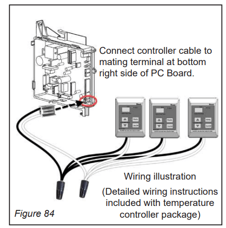
Wiring
A maximum of four temperature controllers can be installed for a water heater or bank of water heaters; this includes the controller built into a Rinnai Tankless Water Heater. Controllers can only be wired in parallel; they cannot be wired in series.
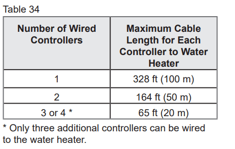
Cable Lengths and Sizes
The temperature controller cable should be a non�polarized two-core cable with a minimum gauge of 22 AWG. The maximum cable length from each temperature controller to the water heater depends on the total number of wired controllers connected to the water heater.
Location
- The temperature controller should be out of reach of small children.
- Avoid locations where the temperature controller may become hot (near an oven or radiant heater).
- Avoid locations in direct sunlight. The digital display may be difficult to read in direct sunlight.
- Avoid locations where the temperature controller could be splashed with liquids.
- Do not install in locations where the temperature controller can be adjusted by the public.